oblozka front page 1biomass.e2ecdn.co.uk/downloads/proton_jet__05010516__en.pdf · check...
TRANSCRIPT

www.protongroup.org
05
01
05
16
ErP2015
Воздушно-отопительный аппарат с насадкой AirJet
OPERATIONS MANUAL FOR AIR HEATER PROTON JET
Safety precautions
Technical parameters Installation
Construction and dimensionsAir Heater with
with AirJet nozzle
PROTON JET
RU
EN
Air Heater with AirJet nozzle
Operations manual for air heater PROTON AST with AirJet nozzle:
1. Introduction .............................................................................................................................................................2. Safety precautions ..............................................................................................................................................
3. General information ............................................................................................................................................
8. Connection of heat medium ...........................................................................................................................
3
4
54. Dimensions and construction........................................................................................................................... 65. Technical characteristics .................................................................................................................................. 7
1011
6. Mounting console ................................................................................................................................................7. Installation .............................................................................................................................................................
9. Control elements ................................................................................................................................................ 1210. Wiring control elements ................................................................................................................................... 1511. Reference information ..................................................................................................................................... 24
2
CONTENTS
8

1. INTRODUCTION
The company PROTON GROUP LLC thanks you for choosing air heaters PROTON.
This manual is an integral part of the product and must always accompany it, and should be transferred to the user.
The user should strictly follow safety instructions while installing, using and servicing the unit.
The manufacturer disclaims any responsibility for damages caused by wrong installation and misuse of the unit.
The manufacturer disclaims any responsibility for damages done by people who didn’t study the manual.
The manufacturer preserves the right to introduce any amendments to the manual without prior notification.
The manufacturer preserves the right to alter the construction which doesn’t impact its functioning and basic technical parameters.
The air heater is intended only and exclusively to be installed and used for purposes which it has been designed. Any misuse or noncompliance with the manufacturer’s instructions may lead to property damages, personnel injuries or death. The user has to take measures to eliminate possibilities of misuse of the unit.
The access to the unit must be restricted for unauthorized and unqualified personnel. The appropriate training of the maintenance sta� should be provided.
To provide proper wiring and application of the unit, please, study this manual thoroughly before installation.
We recommend keeping the manual safe in order to address it during operation.
3

2. SAFETY PRECAUTIONS
55
Обращение
Thermal protection of fan’s motor is built-in and works in a standalone mode.
Current network which feeds the unit’s motor and controls must be additionally protected by a fuse to prevent consequences of shunt fault.
Check compliance of parameters of the electrical supply network to the ones indicated on the unit’s rating plate before connecting to the power supply.
Check grounding. Prohibit the use of the unit without grounding as it may cause property damages, personnel injuries and death.
Check correctness of connections of the system, accordance of the heat medium parameters to the parameters indicated on the rating plate as well as leak proof of joints before filling in the heat medium.
Before any actions connected with the air heater, please, study this manual to provide safety.
Installation and connection of the equipment to pipelines and networks must be performed by qualified personnel only, having appropriate access.
During installation, start-up, repair and maintenance of the air heater follow the safety rules.
Use screws appropriate for the material which the base is made of.
While the air heater is operating under low temperatures, the user must provide protection of the water heat exchanger or use heat medium with special additives preventing copper corrosion.
-t
Avoid substances and impurities in the heat medium causing copper corrosion.
Install the unit on a firm base or surface, which can stand its weight filled with water.
4
Проверьте наличие заземления. Не допускается использование щита управления без заземления, это может привести к повреждению имущества, травмам и гибели персонала.
Во время монтажа, запуска, ремонта и обслуживания щита управления соблюдайте все правила и нормы безопасности.
To prevent defrosting of the air heater’s heat exchanger when circulation of the heat medium is stopped during a heating period under outdoor temperatures lower than 0°C, you need to drain the heat medium from the heat exchanger and blow it o� by compressed air.
NEW

Обращение
5
It is equipped with the AirJet nozzle, which creates the dynamic air movement and increases the reach of the air stream. This unit is designed for heating the premises with the ceiling of up to 16 m high.
The air heater is to be installed vertically, air stream formed by the nozzle will be directed to the necessary zone for heating.
PROTON JET
Application of PROTON JET
PROTON E 15 – мощность нагрева 5-20 кВтPROTON E 25 – мощность нагрева 15-25 кВтPROTON E 35 – мощность нагрева 20-35 кВтPROTON E 45 – мощность нагрева 25-50 кВтPROTON E 55 – мощность нагрева 30-60 кВтPROTON E 65 – мощность нагрева 35-65 кВтPROTON E 75 – мощность нагрева 40-75 кВт
ErP2015
up t
o 1
6 m
3. GENERAL INFORMATION
Principle of operation
The air heater PROTON is an element of a heating system. It is designed for heating air and its even distribution in buildings. Its work is based on axial fan functioning, which charges the air and pass it through a copper-aluminum heat exchanger in which the heat medium (hot water) flows at certain temperature. Heated air is supplied into a room and is directed to the working area by directing louvers.
Out
let
pipe
Inle
t pi
pe
4. DIMENSIONS AND CONSTRUCTION
Обращение
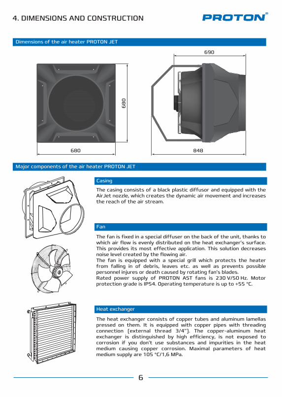
Dimensions of the air heater PROTON JET
6
68
0
680
690
848
Major components of the air heater PROTON JET
Casing
Fan
Heat exchanger
The heat exchanger consists of copper tubes and aluminum lamellas pressed on them. It is equipped with copper pipes with threading connection (external thread 3/4”). The copper-aluminum heat exchanger is distinguished by high e�ciency, is not exposed to corrosion if you don’t use substances and impurities in the heat medium causing copper corrosion. Maximal parameters of heat medium supply are 105 °C/1,6 MPa.
The fan is fixed in a special di�user on the back of the unit, thanks to which air flow is evenly distributed on the heat exchanger’s surface. This provides its most e�ective application. This solution decreases noise level created by the flowing air.The fan is equipped with a special grill which protects the heater from falling in of debris, leaves etc. as well as prevents possible personnel injures or death caused by rotating fan’s blades. Rated power supply of PROTON AST fans is 230 V/50 Hz. Motor protection grade is IP54. Operating temperature is up to +55 °C.
The casing consists of a black plastic di�usor and equipped with the AirJet nozzle, which creates the dynamic air movement and increases the reach of the air stream.
Casing
Fan
The casing consists of a black plastic di�usor and a metal front panel (anemostat), dyed by powder paint. The anemostat is an air distributor serving for supplying and even air distribution in the room as well as lowing air stream speed.
Dimensions of the air heater PROTON JET
4. DIMENSIONS

7
Parameters according to the heat medium
5. TECHNICAL CHARACTERISTICS
General parameters
Parameters according to the heat medium
Number of heat exchanger rows
Airflow
Heating power
Air temperature increase
Max. temperature of heat medium
Max. working pressure
Max. warm air throw
Volume of water in heat exchanger
Diameter of connection pipes
Weight without heat medium
Supply voltage
Motor power
Rated current of motor
Noise level
Motor protection rating
m³/h
kW
°С
°С
MPa
m
dm³
inch
kg
V/Hz
W
dB
А
IP
R
(m³/h) (kW) (kPa)
Pg Qw(°С)
Pp2 p(m³/h) (kW) (kPa)
Pg Qw(°С)
Pp2 p(m³/h) (kW) (kPa)
Pg Qw(°С)
Pp2 p(m³/h) (kW) (kPa)
Pg Qw(°С)
Pp2 p
Water 90/70 Water 80/60 Water 70/50 Water 60/40Parameters (°С) T /z Tp
(m³/h)
Qp
(°С)
Pp1
(m³/h) (kW) (kPa)
Pg Qw(°С)
Pp2 p(m³/h) (kW) (kPa)
Pg Qw(°С)
Pp2 p(m³/h) (kW) (kPa)
Pg Qw(°С)
Pp2 p(m³/h) (kW) (kPa)
Pg Qw(°С)
Pp2 p
Water 90/70 Water 80/60 Water 70/50 Water 60/40Parameters (°С) T /z Tp
(m³/h)
Qp
(°С)
Pp1
0
5
10
15
20
25
0
5
10
15
20
25
Parameters according to the heat medium
0
5
10
15
20
25
(m³/h) (kW) (kPa)
Pg Qw(°С)
Pp2 p(m³/h) (kW) (kPa)
Pg Qw(°С)
Pp2 p(m³/h) (kW) (kPa)
Pg Qw(°С)
Pp2 p(m³/h) (kW) (kPa)
Pg Qw(°С)
Pp2 p
Water 90/70 Water 80/60 Water 70/50 Water 60/40Parameters (°С) T /z Tp
(m³/h)
Qp
(°С)
Pp1
K 310
K 510
K 310 K 510 K 710
5500
17.6
16
1.30
16.5
420
57
2.00
1
105
1.6
3/4
54
230/50
5000
34.5
14
2.25
18.5
420
57
2.00
2
105
1.6
3/4
54
230/50
4500
50.0
12
3.18
20.3
420
57
2.00
3
105
1.6
3/4
54
230/50
32.6 58.1 75.9
32.6 17.6 1.4 10.1 27.8 15.0 1.2 7.7 22.8 12.3 1.0 5.5 17.8 9.6 0.8 3.6
30.5 21.4 1.3 8.9 25.6 18.8 1.1 6.6 20.6 16.1 15.50.9 4.6 13.4 0.7 2.8
28.3 25.2 1.3 7.8 23.4 22.6 1.0 5.6 18.4 19.9 13.30.8 3.7 17.1 0.6 2.1
26.1 29.0 1.2 6.7 21.2 26.3 16.20.9 4.7 23.7 0.7 2.9 10.9 20.9 0.5 2.1
23.9 32.8 1.0 5.7 19.0 30.1 0.8 3.8 13.9 27.4 0.6 2.2 8.6 24.6 0.4 1.0
21.7 36.5 1.0 4.8 16.7 33.9 0.7 3.0 11.6 31.2 0.5 1.6 5.9 28.2 0.3 0.5
55
00
50
00
K 710
58.1 34.5 2.6 18.7 49.7
50.5 39.9
29.5 2.2 14.3 41.2 24.5 1.8 10.3 32.5 19.3 1.4 6.9
54.3 37.2 16.52.4 45.8 32.2 12.32.0 37.3 28.6 22.027.1 1.6 8.6 1.3 5.4
2.2 14.4 42.0 34.8 10.5 33.4 29.8 1.5 7.0 1.124.7 24.6 4.2
46.6 42.5 2.1 12.5 38.1 37.5 1.6
1.4
8.8 29.5 32.4 1.3 5.6 20.7 27.2 0.9 3.0
42.8 45.1 1.9 1.1 4.310.6 34.2 40.1 1.5 7.2 25.6 35.0 16.6 29.8 0.7 2.0
38.9 47.8 1.7 8.9 30.3 42.7 1.3 5.8 21.6 37.6 12.40.9 3.2 32.2 0.5 1.2
75.9 50.0 3.3 23.7 65.2 43.0 2.9 18.2 54.5 36.0 2.4 13.3 43.6 28.8 1.9 9.0
71.0 51.8 3.1 21.0 60.4 44.8 2.7 15.7 49.6 37.7 2.2 11.1 38.6 30.5 1.7 7.2
66.2 53.5 2.9 18.4 55.5 46.5 2.4 13.4 44.7 39.4 1.9 9.2 33.6 32.1 1.5 5.6
61.3 55.2 2.7 15.9 50.6 48.1 2.2 11.3 39.7 41.0 1.7 7.4 28.4 33.7 1.2 4.1
56.4 56.8 2.5 2.013.7 45.6 49.8 9.4 34.7 42.6 1.5 5.8 23.2 35.2 1.0 2.8
51.6 58.5 2.3 11.5 40.7 51.4 1.8 7.6 29.6 44.2 1.3 4.3 17.7 36.5 0.8 1.7
(м³/ч)
Qp
45
00
(°С)
Pp1
0
5
10
15
20
25
Pg
Qw
Pp2p
Pp1 – air temperature at the inlet of the unit– air temperature at the outlet of the unit
– heat power of the unit– air consumptionPp Qp
Pz – water temperature at the inlet of the unit– water temperature at the outlet of the unit
– water pressure drop in heat exchanger– water consumption

М8М8
М8М8
2
3
2
3
2
3
2
3
1
Вентилятор
8
Order of installation
Fasten the mounting console on the air heater’s body using fixing screws and rings .
1 2 3
Use fasteners designed for the material which the base is made of.
.
6. MOUNTING CONSOLE CM 2D

6. КОНСОЛЬ МОНТАЖНАЯ СM 2D
9
6. MOUNTING CONSOLE CM 2D
9120 510
12
62
0Fastening dimensions of the mounting console CM 2D
Ways of installation with mounting console
Noncompliance with the minimal distance (0,25 m) from a wall or ceiling will lead to wrong operation of the air heater which, in turn, will influence the useful life of the equipment.
min
0,2
5 m
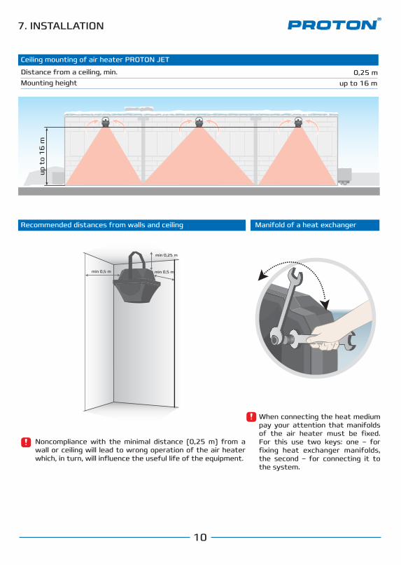
Ceiling mounting of air heater PROTON JET
0,25 m
Êðåïåæíûå ðàçìåðû ìîíòàæíîé êîíñîëè
Distance from a ceiling, min. Mounting height up to 16 m
10
Монтаж аппарата PROTON E 15Recommended distances from walls and ceiling Manifold of a heat exchanger
min 0,5 м min 0,5 м
min 0,15 мmin 0,25 м
Noncompliance with the minimal distance (0,25 m) from a wall or ceiling will lead to wrong operation of the air heater which, in turn, will influence the useful life of the equipment.
When connecting the heat medium pay your attention that manifolds of the air heater must be fixed. For this use two keys: one – for fixing heat exchanger manifolds, the second – for connecting it to the system.
7. INSTALLATIONup
to
16
m
min 0,25 m
min 0,5 mmin 0,5 m
8. CONNECTION OF HEAT MEDIUM
11
Inlet pipeline
Coarse filter
Drain
Switch panel or
Ball cock Ball cockAir outtake Two-way valve with actuator
PROTON JET
Programmable controller
Outlet pipeline0,003
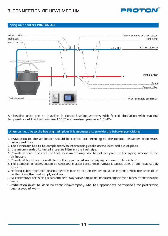
Piping unit heaters PROTON JET
When connecting to the heating main pipes it is necessary to provide the following conditions:
Air heating units can be installed in closed heating systems with forced circulation with maximal temperature of the heat medium 105 °C and maximal pressure 1,6 MPa.
Installation of the air heater should be carried out referring to the minimal distances from walls, ceiling and floor.The air heater has to be completed with intercepting cocks on the inlet and outlet pipes.
1.
2.It is recommended to install a coarse filter on the inlet pipe.3.Provide at least one cock for heat medium drainage on the bottom point on the piping scheme of the air heater.
4.
Provide at least one air outtake on the upper point on the piping scheme of the air heater.5.The diameter of pipes should be selected in accordance with hydraulic calculations of the heat supply system.
6.
Heating tubes from the heating system pipe to the air heater must be installed with the pitch of 3° to the pipes the heat supply system.
7.
All cable trays for wiring a fan and two-way valve should be installed higher than pipes of the heating system.
8.
Installation must be done by technician/company who has appropriate permissions for performing such a type of work.
9.

9. CONTROL ELEMENTS
12
RS 330 Switch panel
The switch is designed to control asynchronous three-speed motor and enables to choose speed of fan operation or to turn it o�. It is equipped with light indicators.
RA Thermostat
The room mechanical thermostat is designed to control temperature in a room regulating the drive of a heat medium supply valve.
Manual setting of fan working mode (HI – high, ME – medium, LO – low, OFF – turned o�). Light indication of chosen rotation speed.Easy to install and simple in use.
Diverse ways to connect a control devise (an actuator or a fan’s motor with help of additional relay).Simple and reliable construction.Availability.Energy savings.
RT 55 Industrial thermostat
Industrial mechanical thermostat is designed to control temperature and regulate heat medium supply by a valve’s drive. The thermostat with IP55 can be installed in various buildings, including dusty and humid environments.
Accurate measurement due to capillary mechanism.Ability to operate in low temperatures (up to 0 °C).Ability to operate in humid and aggressive environments.Ability of direct commutation of electronically-dependent devices.
More information about ECOMATIC PRO you can receive on demand.
ECOMATIC PRO
ECOMATIC PRO is a control element with help of which advantages of heating and ventilation systems become more noticeable and perceivable as its use provide comfortable inside temperature and significant energy savings due to fast response of the system to changes
of climatic conditions in a room. Using PROTON PRO you increase equipment lifetime protecting it from functioning under alarm mode.
9. CONTROL ELEMENTS
13
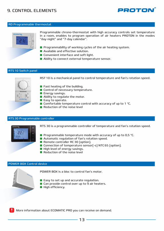
Programmable chrono-thermostat with high accuracy controls set temperature in a room, enables to program operation of air heaters PROTON in the modes “day-night” and “7-day calendar”.
Programmability of working cycles of the air heating system.Available and e�ective solution.Convenient interface and soft light.Ability to connect external temperature sensor.
RTS 10 Switch panel
RST 10 is a mechanical panel to control temperature and fan’s rotation speed.
Fast heating of the building.Control of necessary temperature.Energy savings. Ability to regulate the motor.Easy to operate.Comfortable temperature control with accuracy of up to 1 °C.Reduction of the noise level
POWER BOX Сontrol device
POWER BOX is a bloc to control fan’s motor.
Easy to set up and accurate regulation.Can provide control over up to 9 air heaters.High e�ciency.
RTS 30 Programmable сontroller
RTS 30 is a programmable controller of temperature and fan’s rotation speed.
Programmable temperature mode with accuracy of up to 0,5 °C.Automatic regulation of fan’s rotation speed.Remote controller RC 30 (option).Connection of temperature sensor(-s) NTC 65 (option).High level of energy savings.Reduction of the noise level
RD Programmable thermostat
More information about ECOMATIC PRO you can receive on demand.
9. CONTROL ELEMENTS
14
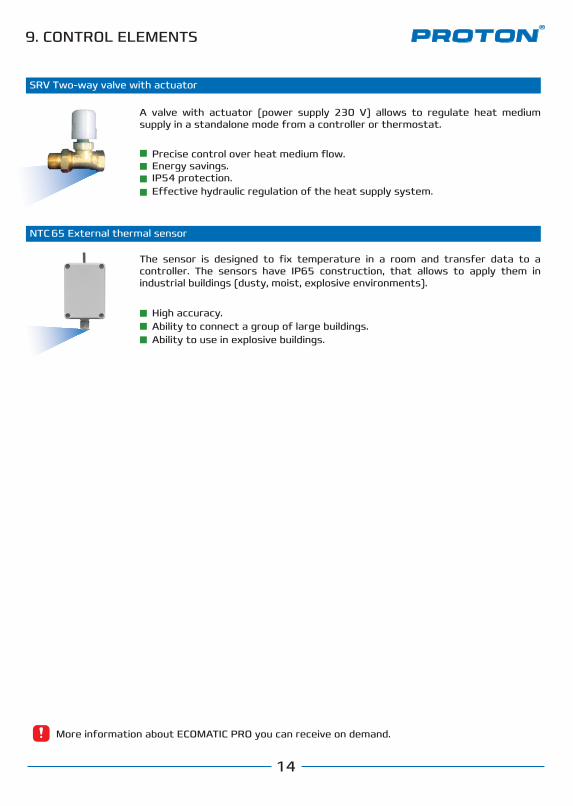
High accuracy.Ability to connect a group of large buildings.Ability to use in explosive buildings.
Precise control over heat medium flow.Energy savings.IP54 protection.E�ective hydraulic regulation of the heat supply system.
A valve with actuator (power supply 230 V) allows to regulate heat medium supply in a standalone mode from a controller or thermostat.
NTC 65 External thermal sensor
The sensor is designed to fix temperature in a room and transfer data to a controller. The sensors have IP65 construction, that allows to apply them in industrial buildings (dusty, moist, explosive environments).
SRV Two-way valve with actuator
More information about ECOMATIC PRO you can receive on demand.

10. WIRING CONTROL ELEMENTS
15
10.1
HI
OFF OFF
ME LO
NPE LO HIME
23
0 V
/50
Hz
L N PE
B4
RS 330
LO LHI ME 1
NPE LO HIME
Provide installation of a device protecting the motor from shunt fault (B on the scheme).
4
Single-phase three-speedAC-motor
Single-phase three-speedAC-motor
Wiring of single-phase three-speed AC-motor to switch panelRS 330
16
10.2
11.2 3.1 Подключение однофазных трехскоростных АС-двигателей к блоку управления POWER BOX с пультом механическим RTS 10 (подключение несколькиих вентиляторов к одному каналу)
Single-phase three-speedAC-motor
Однофазный трехскоростнойАС-двигатель
Однофазный трехскоростнойАС-двигатель
HI
OFF OFF
ME LO
13 4
RS 330
LO LHI ME 1
NPE LO HIME
23
0 V
/50
Hz
L N PE
B4
N
SRV
V
RA
RDNTC65
RT 55
VL
VL
1PE 2С
VL
11 10 9 8 7 6 5
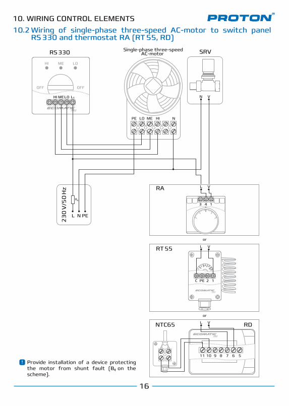
10. WIRING CONTROL ELEMENTSWiring of single-phase three-speed AC-motor to switch panel RS 330 and thermostat RA (RT 55, RD)
Подключение однофазного трехскоростного АС-двигателя к переключателю RS 330 и термостату RA (RT 55, RD)11. WIRING CONTROL ELEMENTS
4
Provide installation of a device protecting the motor from shunt fault (B on the scheme).
4
or
or

17
10.3
Single-phase three-speedAC-motor
Single-phase three-speedAC-motor
RTS 10
HEAT
OFF
COOL
HIGH
MED
LOW
9 8 7 6
1 2 3 4 5
NPE LO HIME
N
SRV
N
SRV
L N PE
B4
V
V
NPE LO HIME
23
0 V
/50
Hz
10. WIRING CONTROL ELEMENTSWiring of single-phase three-speed AC-motors to the switch panel RTS 10 (having reached set temperature in a room the valve SRV closes)
Provide installation of a device protecting the motor from shunt fault (B on the scheme).
4
18
10.4
Single-phase three-speedAC-motor
Single-phase three-speedAC-motor
RTS 10
HEAT
OFF
COOL
HIGH
MED
LOW
9 8 7 6
1 2 3 4 5
NPE LO HIME
L N PE
B4
NPE LO HIME
23
0 V
/50
Hz
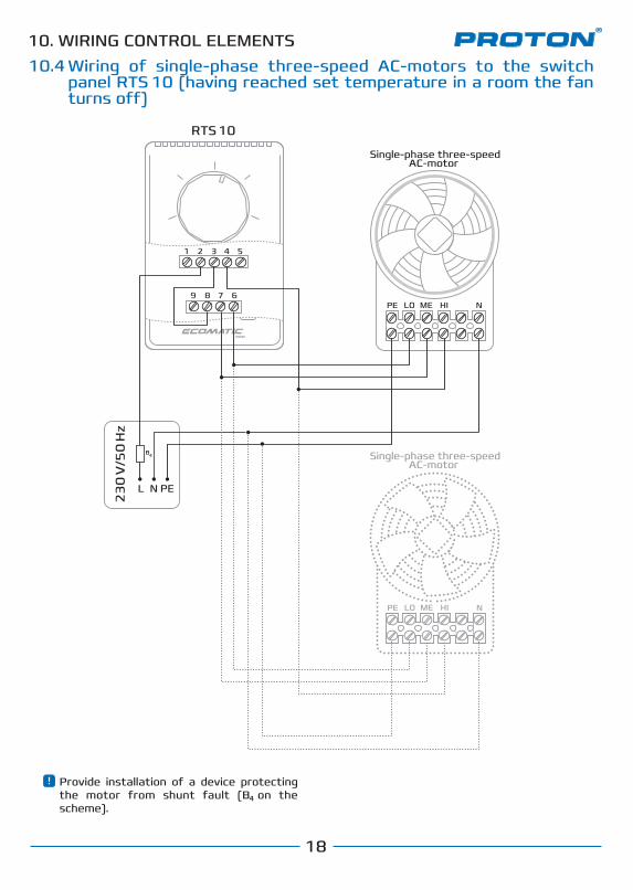
10. WIRING CONTROL ELEMENTSWiring of single-phase three-speed AC-motors to the switchpanel RTS 10 (having reached set temperature in a room the fan turns o�)
Provide installation of a device protecting the motor from shunt fault (B on the scheme).
4
Wiring of single-phase three-speed AC-motors to the switch panel RTS 10 (having reached set temperature in a room the valve SRV closes)
19
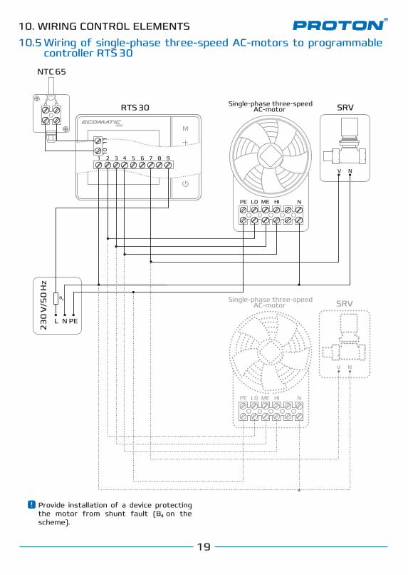
10.5
Single-phase three-speedAC-motor
Single-phase three-speedAC-motor
N
SRV
V
NPE LO HIME
N
SRV
RTS 30
1 2 3 4 5 6 7 8 9
NTC 65
10
11
L N PE
B4
V
NPE LO HIME
23
0 V
/50
Hz
10. WIRING CONTROL ELEMENTSWiring of single-phase three-speed AC-motors to programmable сontroller RTS 30
Provide installation of a device protecting the motor from shunt fault (B on the scheme).
4

20
10.6
Single-phase three-speedAC-motor
Single-phase three-speedAC-motor
Single-phase three-speedAC-motor
RTS 10
HEAT
OFF
COOL
HIGH
MED
LOW
9 8 7 6
1 2 3 4 5
Up to 3 air heaters can be connected to one line.
NPE LO HIME
N
SRV
V
NPE LO HIME
N
SRV
V
POWER BOX
1 2 3 4 5 6 1 2 3 4 5 6 1 2 3 4 5 6
LO
PE N V
ME HI 7654321
23
0 V
/50
Hz
L N PE
B4
N
SRV
V
NPE LO HIME
Up to 9 air heaters can be connected.
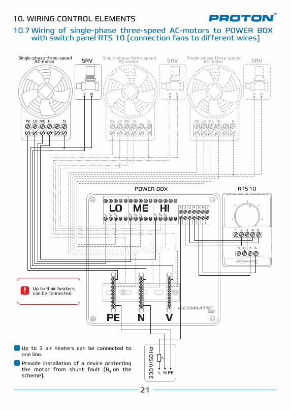
10. WIRING CONTROL ELEMENTSWiring of single-phase three-speed AC-motors to POWER BOX with switch panel RTS 10 (connection of a few fans to one wire)
Provide installation of a device protecting the motor from shunt fault (B on the scheme).
4
21
10.7
NPE LO HIME
NV
NPE LO HIME
NV
POWER BOX
1 2 3 4 5 6 1 2 3 4 5 6 1 2 3 4 5 6
LO
PE N V
ME HI 7654321
L N PE
B4
Up to 9 air heaters can be connected.
NV
RTS 10
HEAT
OFF
COOL
HIGH
MED
LOW
9 8 7 6
1 2 3 4 5
NPE LO HIME
Up to 3 air heaters can be connected to one line.
Provide installation of a device protecting the motor from shunt fault (B on the scheme).
4
23
0 V
/50
Hz
10. WIRING CONTROL ELEMENTSWiring of single-phase three-speed AC-motors to POWER BOX with switch panel RTS 10 (connection fans to di�erent wires)
Single-phase three-speedAC-motor
Single-phase three-speedAC-motor
Single-phase three-speedAC-motor SRV SRVSRV
22
10.8
RTS 30
1 2 3 4 5 6 7 8 9
NTC 651
01
1
NPE LO HIME
NV
NPE LO HIME
NV
POWER BOX
1 2 3 4 5 6 1 2 3 4 5 6 1 2 3 4 5 6
LO
PE N V
ME HI 7654321
23
0 V
/50
Hz
L N PE
B4
NV
NPE LO HIME
Single-phase three-speedAC-motor
Single-phase three-speedAC-motor
Single-phase three-speedAC-motor SRV SRVSRV
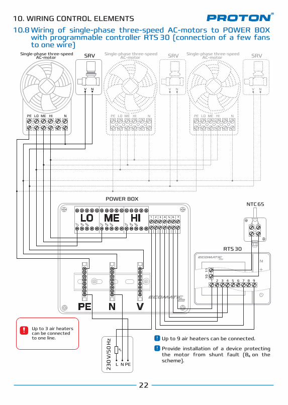
10. WIRING CONTROL ELEMENTSWiring of single-phase three-speed AC-motors to POWER BOX with programmable сontroller RTS 30 (connection of a few fans to one wire)
Up to 3 air heaters can be connected to one line. Up to 9 air heaters can be connected.
Provide installation of a device protecting the motor from shunt fault (B on the scheme).
4

23
10.9
RTS 30
1 2 3 4 5 6 7 8 9
NTC 65
10
11
NPE LO HIME
NV
NPE LO HIME
NV
POWER BOX
1 2 3 4 5 6 1 2 3 4 5 6 1 2 3 4 5 6
LO
PE N V
ME HI 7654321
23
0 V
/50
Hz
L N PE
B4
NV
NPE LO HIME
SRV SRVSRV
10. WIRING CONTROL ELEMENTSWiring of single-phase three-speed AC-motors to POWER BOX with programmable сontroller RTS 30 (connection of fans to di�erent wires)
Single-phase three-speedAC-motor
Single-phase three-speedAC-motor
Single-phase three-speedAC-motor
Up to 9 air heaters can be connected.
Up to 3 air heaters can be connected to one line.
Provide installation of a device protecting the motor from shunt fault (B on the scheme).
4
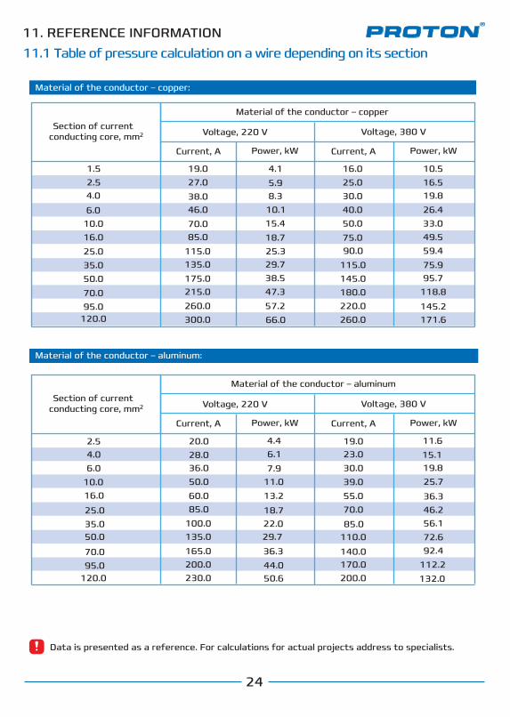
11. REFERENCE INFORMATION11.1 Table of pressure calculation on a wire depending on its section
24
Data is presented as a reference. For calculations for actual projects address to specialists.
Section of current conducting core, mm
Material of the conductor – copper
Voltage, 220 V Voltage, 380 V
Current, A Power, kW Current, A Power, kW
1.52.54.0
6.010.016.025.035.050.070.095.0
120.0
4.15.98.3
10.115.418.725.329.738.547.357.266.0
10.516.519.826.4
49.559.475.995.7
118.8
145.2171.6
11.615.119.825.7
36.346.256.172.692.4
112.2132.0
4.46.17.9
13.2
18.7
29.7
50.6
36.3
22.0
44.0
11.0
19.027.038.046.070.085.0
115.0135.0175.0215.0260.0300.0
20.028.036.050.060.085.0
100.0135.0
165.0200.0230.0
19.023.030.039.055.070.0
85.0110.0
140.0170.0200.0
16.025.030.040.050.075.090.0
115.0145.0180.0220.0260.0
33.0
Material of the conductor – aluminum:
Material of the conductor – aluminum
2.54.06.0
10.016.0
25.035.050.0
70.095.0
120.0
2
Material of the conductor – copper:
Section of current conducting core, mm Voltage, 220 V Voltage, 380 V
Current, A Power, kW Current, A Power, kW
2

11.2 Recommended diameters of pipes depending on power of equipment’s heat output
25
kW Water consumption Inside diameter Type
15 kW
23 kW
39 kW
61 kW
96 kW
180 kW
20 mm
25 mm
32 mm
40 mm
50 mm
70 mm
3/4
1
1 14
1
2
2
0.6 m³/h
1.0 m³/h
1.6 m³/h
2.5 m³/h
4.0 m³/h
8.0 m³/h
12
12
11. REFERENCE INFORMATION
Data is presented as a reference. For calculations for actual projects address to specialists.

26
Нагревательные элементы, установленные в завесах PROTON HD POWER выполнены из высоколегированной нержавеющей стали. Для лучшего съема тепла в конструкцию нагревательного элемента добавлены ребра, представляющие собой торообразную спираль шириной 10 мм с дополнительной гофровкой. Рама крепления ТЭНРов выполнена из оцинкованной стали. Клеммы коробки подключения оснащены зажимными кабель-вводами. Термодатчики защиты ТЭНРов от перегрева смонтированы в верхней и нижней части группы ТЭНРов.
Электрические ТЄНРы
Модельный ряд
PROTON E 15 – мощность нагрева 5-20 кВтPROTON E 25 – мощность нагрева 15-25 кВтPROTON E 35 – мощность нагрева 20-35 кВтPROTON E 45 – мощность нагрева 25-50 кВтPROTON E 55 – мощность нагрева 30-60 кВтPROTON E 65 – мощность нагрева 35-65 кВтPROTON E 75 – мощность нагрева 40-75 кВт
Корпус
Направляющие жалюзи
Электрические ТЄНРы
Сечение указано как минимально допустимое для медных проводов. Максимальное расстояние от щита управления ECOMATIC RDE до завес PROTON HD POWER не должно привышать 20 м.
12. СПРАВОЧНАЯ ИНФОРМАЦИЯFOR NOTES

27
Нагревательные элементы, установленные в завесах PROTON HD POWER выполнены из высоколегированной нержавеющей стали. Для лучшего съема тепла в конструкцию нагревательного элемента добавлены ребра, представляющие собой торообразную спираль шириной 10 мм с дополнительной гофровкой. Рама крепления ТЭНРов выполнена из оцинкованной стали. Клеммы коробки подключения оснащены зажимными кабель-вводами. Термодатчики защиты ТЭНРов от перегрева смонтированы в верхней и нижней части группы ТЭНРов.
Электрические ТЄНРы
Модельный ряд
PROTON E 15 – мощность нагрева 5-20 кВтPROTON E 25 – мощность нагрева 15-25 кВтPROTON E 35 – мощность нагрева 20-35 кВтPROTON E 45 – мощность нагрева 25-50 кВтPROTON E 55 – мощность нагрева 30-60 кВтPROTON E 65 – мощность нагрева 35-65 кВтPROTON E 75 – мощность нагрева 40-75 кВт
Корпус
Направляющие жалюзи
Электрические ТЄНРы
Сечение указано как минимально допустимое для медных проводов. Максимальное расстояние от щита управления ECOMATIC RDE до завес PROTON HD POWER не должно привышать 20 м.
12. СПРАВОЧНАЯ ИНФОРМАЦИЯFOR NOTES

PROTON GROUP LLC03680, Ukraine, Kyiv, 3, Nesterova str.Tel.: +380 (44) 537 0930Fax: +380 (44) 537 0903E-mail: [email protected]
www.protongroup.org
In case of any failures in operation of equipment address the authorized support centers of the Manufacturer.For information about support centers and procedure of claim submission contact Manufacturer’s service department:
Service department