obstacle avoidance legged robot. mohamed faizan bin...
TRANSCRIPT
OBSTACLE AVOIDANCE LEGGED ROBOT.
MOHAMED FAIZAN BIN BASHEER AHMAD
This thesis is submitted as partial fulfillment of the requirement for the
award of the Bachelor Degree of Electrical Engineering (Electronic)
Faculty of Electrical & Electronic Engineering
University Malaysia Pahang
NOVEMBER 2008
ii
DECLARATION
“All the trademark and copyrights use here in are property of their respective owner.
References of information from other sources are quoted accordingly, otherwise the
information presented in this report is solely work of the author”.
Signature : ________________________________________
Author : MOHAMED FAIZAN BIN BASHEER AHMAD.
Date : 21 NOVEMBER 2008.

iii
DEDICATION
Specially dedicate to
My beloved parents, brothers and sisters.

iv
ACKNOWLEDGEMENT
First, I would like to express highest gratitude to my supervisor, Encik Saifudin
b. Razali for the guidance and co-operation that been given throughout the progress and
completion of this project.
I also deeply thank to my family who‟s always giving a motivational support and
show me a guidance to pursue my studies at University Malaysia Pahang. Thanks for
their encouragement, support, love, my brothers, sister and many more.
ALHAMDULILLAH.
Finally, my great appreciation to my dear housemates that given me so many
opinion and encouragement till I don‟t know which one to comprehend, especially Hanis
, Khawarizmi and Mohd Noor thanks for their brilliant idea and my class mate whom
involve directly or indirectly with this project. Last but not least the dedication of a
thousand of thank to dear Hasinah that is a special one to me that had always been a
backbone for me and gave plenty of motivation, moral support and so on. Finally thank
you Allah since through your blessings I managed to do all in time. Thank You very
Much.
v
ABSTRACT
Many mobile robots require an operator‟s vision and intelligence for guidance
and navigation. Animals use sensory systems such as hearing, and tactile to move freely
through their environment. The aim of this project is to develop an avoidance behaviors
program for a mobile robot that consists of 8 servo motors that been employed at 4 legs.
Each leg contains 2 servo motors, one for X-axis and one for Y-axis. A PIC
Microcontroller has been implemented to act as a brain for the robot that controls the
walking and turning algorithm. Ultrasonic sensor was also developed to act as an „eye‟
to the system and tells the brain about existence of obstacle in front. As a resultant, the
obstacle avoidance legged robot system is been successfully developed that allows and
will navigate the robot to move through the environment freely. But there is a certain
limitation for the robot such as the wideness of the area, type of obstacle and surface.
vi
ABSTRAK
Di dalam dunia permodenan dan kontemporari seperti ini robot memerlukan
operator dan kebijaksanaan wawasan untuk tujuan panduan hala tujunya. Demikian
adalah cara yang digunakan haiwan iaitu sistem-sistem deria pendengaran, dan sentuhan
untuk bergerak dengan lebih bebas menerusi alam sekitar mereka. Matlamat projek ini
adalah untuk membangunkan satu pergerakan pengelakan atur cara untuk satu
kepergerakan robot yang mengandungi 8 servo motor yang berfungsi di setiap kaki.
Keseluruhan robot itu mempunyai 4 kaki dan pada tiap kaki mengandungi 2 servo motor
, satu untuk pergerakkan paksi X dan satu lagi untuk pergerakkan paksi Y. Satu PIC
Microcontroller telah digunakan dan ia berfungsi sebagai satu otak untuk mengawal
robot itu dengan wujudnya algoritma berjalan dan algoritma selekoh. Deria ultrasonik
juga dibuat supaya ia berfungsi sebagai satu 'mata' bagi robot itu.
vii
TABLE OF CONTENT
Title Page i
Declaration ii
Dedication iii
Acknowledgement iv
Abstract v
Abstrak vi
Table of Contents vii
List of Chapter viii
List of Table xi
List of Figures xii
List of Symbol xiv
List of Appendices xv
viii
LIST OF CHAPTER
CHAPTERS TITLE PAGES
1 INTRODUCTION
1.1 Overview 1
1.2 Objective of the Project. 2
1.3 Scope of Project. 2
1.4 Outline of Thesis. 3
2 THEORY AND LITERATURE REVIEW
2.1 Introduction. 4
2.2 Servo Motors. 4
2.2.1 Pulse Width Modulation for Servo. 7
2.2.2 Inside Servo. 8
2.3 PIC Microcontroller. 9
2.4 Robotics. 14
2.4.1 Robot Component. 15
2.4.2 Robot Kinematics: Position Analysis 16
2.4.3 Denavit-Hartenberg Representation 18
2.5 Sensors. 21
2.5.1 Proximity Sensors. 23
2.5.2 Optical Proximity Sensors. 23
2.5.3 Infrared Sensors. 24
2.5.4 Ultrasonic Proximity Sensors. 25
ix
3 SYSTEM DESIGN
3.1 Introduction. 27
3.2 Hardware Implementation. 29
3.2.1 Power Supply Module. 29
3.2.2 PIC Micrcontroller. 30
3.2.3.1 PIC. 31
3.2.3.1 Oscillator and Reset. 32
3.2.3.1 Programmer. 33
3.2.3.1 LED Connection. 34
3.2.4 Servo Motor. 35
3.2.5 Ultrasonic Sensor. 37
3.2.6 The Robot Movement Design. 41
3.2.6.1 Walking Algorithm. 42
3.2.6.2 Turning Algorithm. 45
3.3 Software Implementation. 47
3.3.1 Algorithm and Programming. 47
3.3.2 Processing Explanation of Main Program. 48
3.3.2.1 Initialize. 49
3.3.2.2 PWM Generation. 50
3.3.2.3 Analog to Digital Converter. 52
3.3.2.4 Sensor Detection. 53
4 RESULT AND ANALYSIS.
4.1 Introduction. 55
4.2 Total Result Robot Algorithm. 56
4.3 Mathematical Expression of the Leg. 60
x
5 CONCLUTION AND RECOMMENDATION.
5.1 Conclusion. 63
5.2 Problem and Solution. 64
5.3 Recommendation. 65
5.4 Costing and Commercialization 66
REFERENCE 68
xi
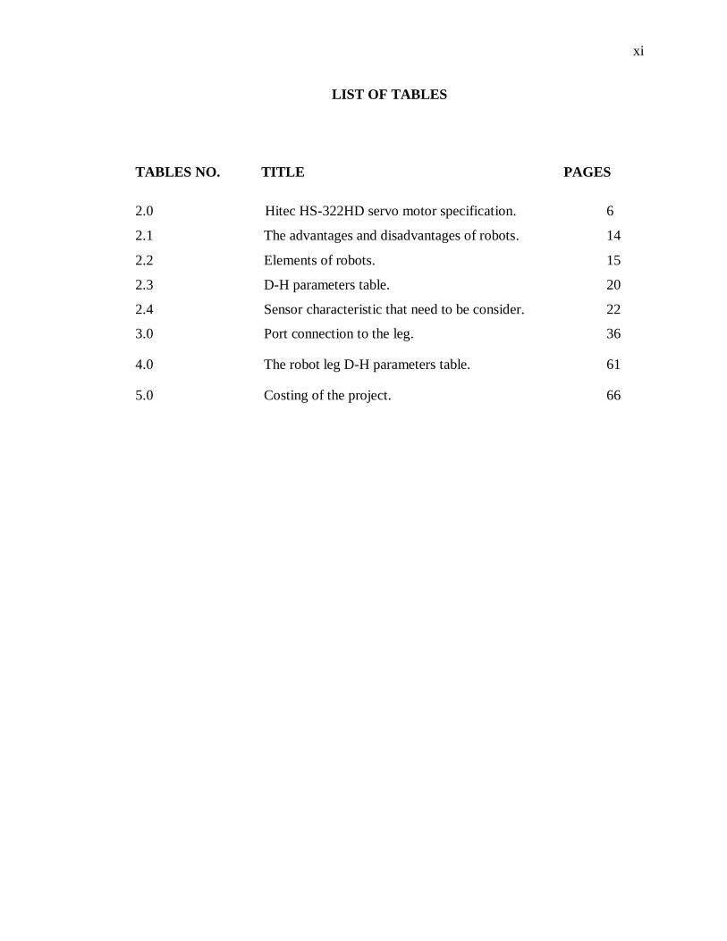
LIST OF TABLES
TABLES NO. TITLE PAGES
2.0 Hitec HS-322HD servo motor specification. 6
2.1 The advantages and disadvantages of robots. 14
2.2 Elements of robots. 15
2.3 D-H parameters table. 20
2.4 Sensor characteristic that need to be consider. 22
3.0 Port connection to the leg. 36
4.0 The robot leg D-H parameters table. 61
5.0 Costing of the project. 66
xii
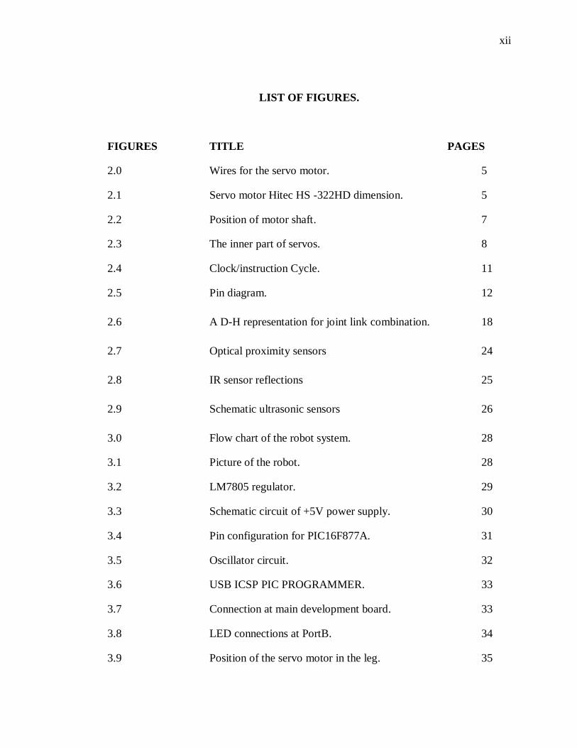
LIST OF FIGURES.
FIGURES TITLE PAGES
2.0 Wires for the servo motor. 5
2.1 Servo motor Hitec HS -322HD dimension. 5
2.2 Position of motor shaft. 7
2.3 The inner part of servos. 8
2.4 Clock/instruction Cycle. 11
2.5 Pin diagram. 12
2.6 A D-H representation for joint link combination. 18
2.7 Optical proximity sensors 24
2.8 IR sensor reflections 25
2.9 Schematic ultrasonic sensors 26
3.0 Flow chart of the robot system. 28
3.1 Picture of the robot. 28
3.2 LM7805 regulator. 29
3.3 Schematic circuit of +5V power supply. 30
3.4 Pin configuration for PIC16F877A. 31
3.5 Oscillator circuit. 32
3.6 USB ICSP PIC PROGRAMMER. 33
3.7 Connection at main development board. 33
3.8 LED connections at PortB. 34
3.9 Position of the servo motor in the leg. 35
xiii
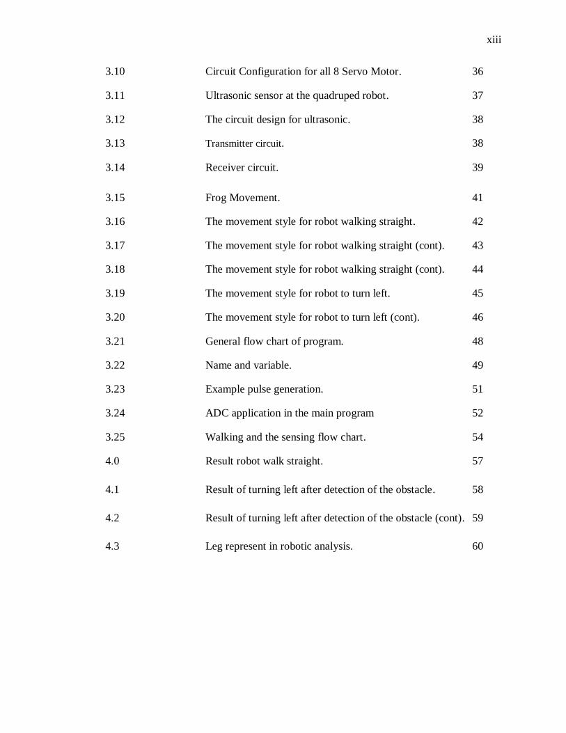
3.10 Circuit Configuration for all 8 Servo Motor. 36
3.11 Ultrasonic sensor at the quadruped robot. 37
3.12 The circuit design for ultrasonic. 38
3.13 Transmitter circuit. 38
3.14 Receiver circuit. 39
3.15 Frog Movement. 41
3.16 The movement style for robot walking straight. 42
3.17 The movement style for robot walking straight (cont). 43
3.18 The movement style for robot walking straight (cont). 44
3.19 The movement style for robot to turn left. 45
3.20 The movement style for robot to turn left (cont). 46
3.21 General flow chart of program. 48
3.22 Name and variable. 49
3.23 Example pulse generation. 51
3.24 ADC application in the main program 52
3.25 Walking and the sensing flow chart. 54
4.0 Result robot walk straight. 57
4.1 Result of turning left after detection of the obstacle. 58
4.2 Result of turning left after detection of the obstacle (cont). 59
4.3 Leg represent in robotic analysis. 60
xiv
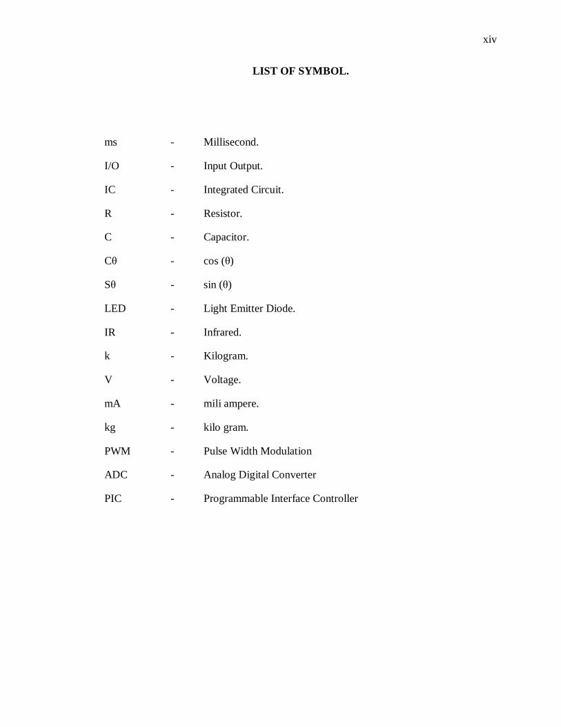
LIST OF SYMBOL.
ms - Millisecond.
I/O - Input Output.
IC - Integrated Circuit.
R - Resistor.
C - Capacitor.
Cθ - cos (θ)
Sθ - sin (θ)
LED - Light Emitter Diode.
IR - Infrared.
k - Kilogram.
V - Voltage.
mA - mili ampere.
kg - kilo gram.
PWM - Pulse Width Modulation
ADC - Analog Digital Converter
PIC - Programmable Interface Controller
xv
LIST OF APPENDICES.
APPENDIX TITLE PAGE
A SOFTWARE DEVELOPMENT 69
B MICROCHIP PIC16F877A DATA SHEET. 78
LM7805 DATA SHEET. 81
HITEC HD-322HD DATA SHEET. 82
CHAPTER 1
INTRODUCTION
1.1 OVERVIEW.
Robots are designed to be controlled by a controller, computer or similar devices.
Basically mobile robots require an operator’s vision and intelligence for guidance and
navigation. The movement for the robot itself has many methods such as wheels, legs
and many more. This movement method is to ensure the smoothness of moving in
different type of surfaces.
A simple wheeled vehicle is easy in mechanical design, controlling, and the
construction part. But it doesn’t work efficiently in all kind of surface. On a rough
terrain, it performs poorly. The radius of a wheel could pass only a certain height of
obstacle. To pass most of the obstacle that it meets, larger wheel radius need to be
designed. However, this approach is impractical in many cases.
On the other side, legged robots are more capable of moving across rough
terrain. That’s why the legged locomotion became a research of interest. But the legged
robots are much more challenging to control compared wheel robots. Each leg consists
of at least two motors. Controlling the one motor for left and right and another motor for
2
up and down is difficult. An algorithm for walking must be developed in order the robot
to walk. As a result, legged robots movement must be carefully studied and be
controlled in such way so that it could stand and walk in a stable fashion.
1.2 OBJECTIVE OF THE PROJECT.
The aim of this project is to develop an avoidance behaviors program for a
mobile robot that consists of 4 legs that employs 8 servo motors. A PIC Microcontroller
is been implemented to act as the brain for the robot that controls the walking and
turning algorithm. The system and the programming will be able to control the
movement of the legged so the robot able to walk straight ahead, make left turns and
avoid obstacle.
1.3 SCOPE OF PROJECT.
Several scopes have been outlined to achieve this project. Scope of this project
includes developing a program using high level language PIC Basic Pro for the
PIC16F877A microcontroller, constructing the hardware module for it, attachment of
servo motors and integration of ultrasonic sensor with the microcontroller. Developing
an algorithm program for the robot to walk ahead, make a left turn and is capable to
avoid obstacle.
3
1.4 OUTLINE OF THESIS.
This thesis consists of five chapters. This chapter is discussed about the
background of robot, the objective, and scope of the project. In chapter 2 is more
towards reviewing about literature study. It discusses about the function of the servo
motor and it could be operated using PWM, about details of PIC16F877A
microcontroller, about other robotic research that been done and about various type of
sensor. In chapter 3 is been discussed about methodology for hardware and software
implementation into the project. The result, analysis and discussion will be on the
chapter 4. Finally, chapter 5 discusses the conclusion of the project and future work that
can be done to improvise this project.
CHAPTER 2
THEORY AND LITERATURE REVIEW
2.1 INTRODUCTION.
This chapter is upon the study on servo motor, PIC microcontroller, robots
analysis and sensors. Servo motor was reviewed upon controlling it using PWM and
how it could be used as a device that controls a degree of freedom in a quadruped robot.
The PIC microcontroller discussed more towards the capability of it and thorough detail
on the functions and the operations of it. Type of sensors compared in this chapter.
2.2 SERVO MOTORS.
Servo motors are commonly used in robotics especially that uses leg for
movement purpose for the robot. This was because they are light-weighted, compact and
durable. Since their control and power electronics were all built-in, interfacing hardware
5
requirement is much simplified. Compared to toy motors, the torque of servo motors are
high so the servo motors better suited to robot development.
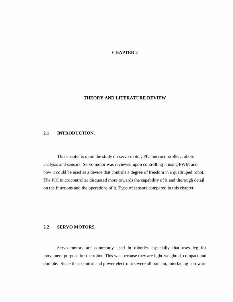
Each servo motor has three wires, that is yellow, red and black. As shown in
Figure 2.0 red is for power, black is for ground, and yellow is for pulse-width
modulation (PWM) pulsing. This pulsing controls the position which the shaft of a servo
motor should rotate.
Figure 2.0: Wires for the servo motor, black (ground), red (power), yellow (PWM)
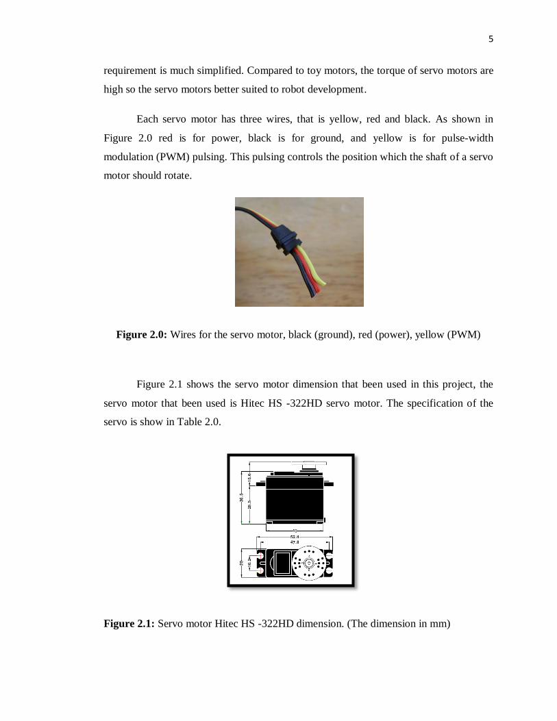
Figure 2.1 shows the servo motor dimension that been used in this project, the
servo motor that been used is Hitec HS -322HD servo motor. The specification of the
servo is show in Table 2.0.
Figure 2.1: Servo motor Hitec HS -322HD dimension. (The dimension in mm)
6
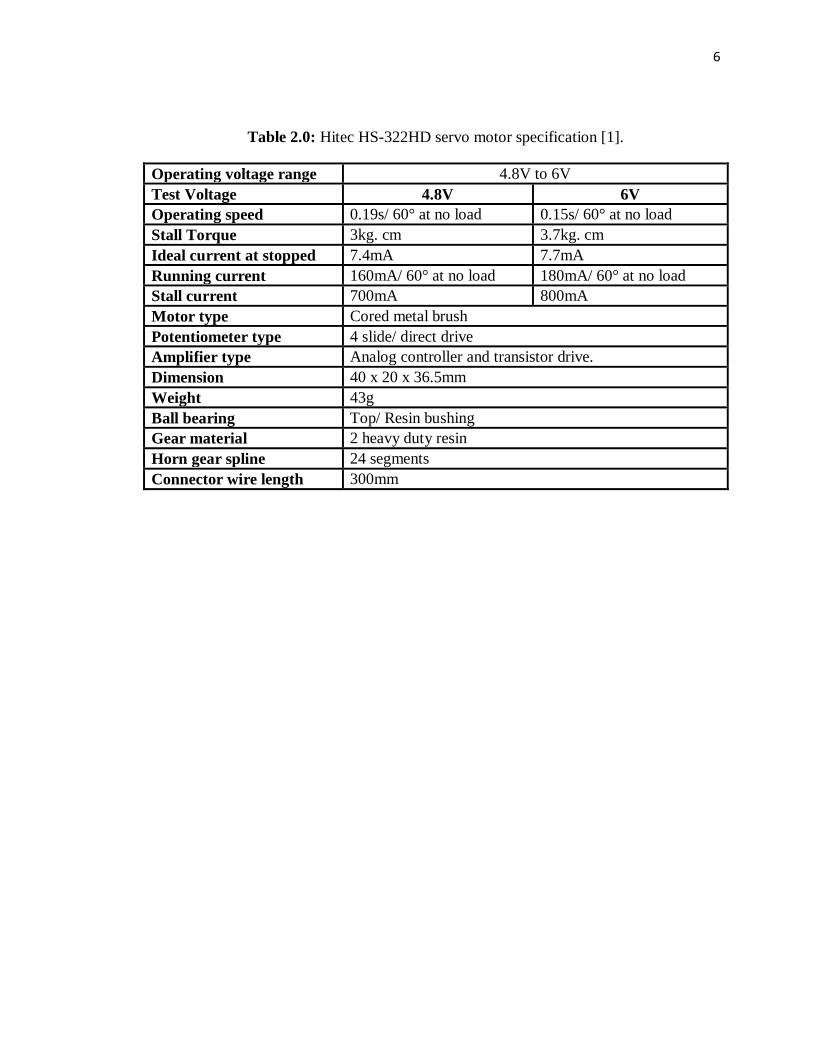
Table 2.0: Hitec HS-322HD servo motor specification [1].
Operating voltage range 4.8V to 6V
Test Voltage 4.8V 6V
Operating speed 0.19s/ 60° at no load 0.15s/ 60° at no load
Stall Torque 3kg. cm 3.7kg. cm
Ideal current at stopped 7.4mA 7.7mA
Running current 160mA/ 60° at no load 180mA/ 60° at no load
Stall current 700mA 800mA
Motor type Cored metal brush
Potentiometer type 4 slide/ direct drive
Amplifier type Analog controller and transistor drive.
Dimension 40 x 20 x 36.5mm
Weight 43g
Ball bearing Top/ Resin bushing
Gear material 2 heavy duty resin
Horn gear spline 24 segments
Connector wire length 300mm
7
2.2.1 PULSE WIDTH MODULATION FOR SERVO
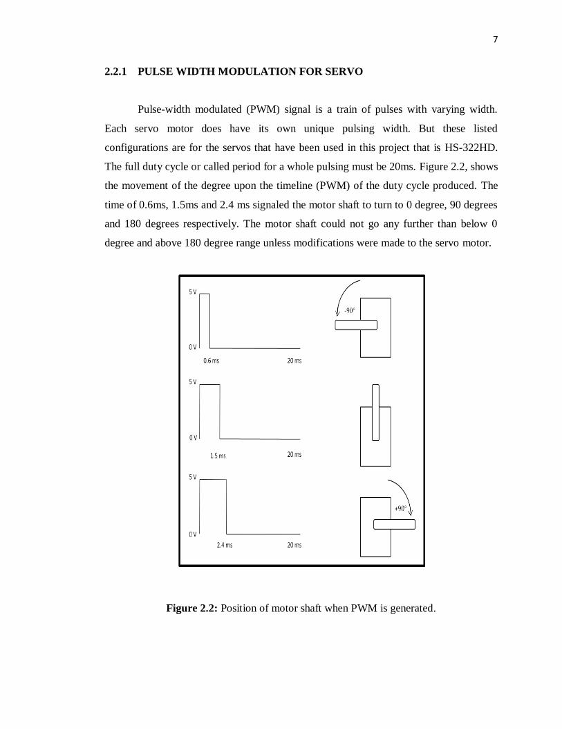
Pulse-width modulated (PWM) signal is a train of pulses with varying width.
Each servo motor does have its own unique pulsing width. But these listed
configurations are for the servos that have been used in this project that is HS-322HD.
The full duty cycle or called period for a whole pulsing must be 20ms. Figure 2.2, shows
the movement of the degree upon the timeline (PWM) of the duty cycle produced. The
time of 0.6ms, 1.5ms and 2.4 ms signaled the motor shaft to turn to 0 degree, 90 degrees
and 180 degrees respectively. The motor shaft could not go any further than below 0
degree and above 180 degree range unless modifications were made to the servo motor.
Figure 2.2: Position of motor shaft when PWM is generated.
8
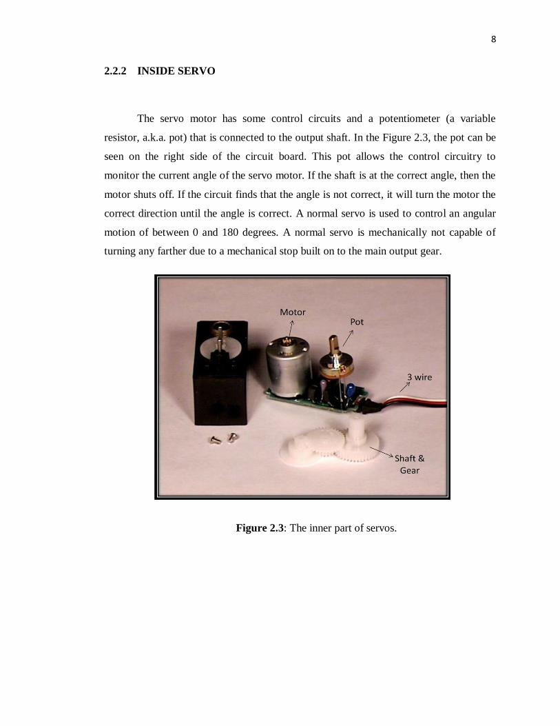
2.2.2 INSIDE SERVO
The servo motor has some control circuits and a potentiometer (a variable
resistor, a.k.a. pot) that is connected to the output shaft. In the Figure 2.3, the pot can be
seen on the right side of the circuit board. This pot allows the control circuitry to
monitor the current angle of the servo motor. If the shaft is at the correct angle, then the
motor shuts off. If the circuit finds that the angle is not correct, it will turn the motor the
correct direction until the angle is correct. A normal servo is used to control an angular
motion of between 0 and 180 degrees. A normal servo is mechanically not capable of
turning any farther due to a mechanical stop built on to the main output gear.
Figure 2.3: The inner part of servos.
9
2.3 PIC MICROCONTROLLER
For this project, the controller is used as a brain for the whole system. From the
input from sensor until the output for the servo motor is controlled totally using this PIC
microcontroller. Describing about the PIC microcontroller and in the mean time will be
given more understanding upon employing this controller. Almost all type of PIC
microcontroller is included in a class of 8-bit microcontrollers of RISC architecture.
Basically, the PIC architecture is minimized to be a simpler item but it still operates at
the same function. The Harvard architecture is a newer concept than von-Neumann. It
was designed as a response for the need to speed up the work of a microcontroller. In
Harvard architecture, data bus and address bus are separate. Thus, the data will flow
directly through the central processing unit and the address bus is neglected. This greater
flow of data will impact for a greater speed of work. Besides that, the architecture will
involve for a small number of a fixed length instruction. It means the instruction is not to
have to be 8-bit words but it can uses 14 bits for instructions which allows for all
instruction to be one word instructions. Microcontrollers with Harvard architecture are
called "RISC microcontrollers". RISC is a short form for Reduced Instruction Set
Computer. Microcontrollers with von-Neumann's architecture are called 'CISC
microcontrollers'. CISC is a short form for Complex Instruction Set Computer. Same as
discussion before, RISC microcontroller has a reduced set of instructions, maybe 35
instructions for one cycle. If we compared it with Intel’s and Motorola’s
microcontroller, it has over hundred instructions. As a simplified point, we can say that
the features of PIC microcontroller are:
(i) Separate code and data spaces (Harvard architecture).
(ii) A small number of fixed length instructions.
(iii) Most instructions are single cycle execution (4 clock cycles), with single
delay cycles upon branches and skips.
(iv) All RAM locations function as registers as both source and/or destination of
math and other functions.
(v) A hardware stack for storing return addresses.