obstacle detection and collision avoidance for a uav with ...obstacle detection and collision...
TRANSCRIPT
Received April 14, 2015, accepted May 5, 2015, date of publication May 12, 2015, date of current version June 1, 2015.
Digital Object Identifier 10.1109/ACCESS.2015.2432455
Obstacle Detection and Collision Avoidance for aUAV With Complementary Low-Cost SensorsNILS GAGEIK, PAUL BENZ, AND SERGIO MONTENEGROChair Aerospace Information Technology, University of Würzburg, Würzburg 97074, Germany
Corresponding author: N. Gageik ([email protected])
This work was supported in part by the Würzburg-Schweinfurt Chamber of Industry and Commerce, in part by the UniversitätsbundWürzburg, Würzburg, Germany, in part by the German Research Foundation, and in part by the University of Wuerzburg within thefunding programme Open Access Publishing.
ABSTRACT This paper demonstrates an innovative and simple solution for obstacle detection and collisionavoidance of unmanned aerial vehicles (UAVs) optimized for and evaluated with quadrotors. The sensorsexploited in this paper are low-cost ultrasonic and infrared range finders, which are much cheaper thoughnoisier than more expensive sensors such as laser scanners. This needs to be taken into consideration forthe design, implementation, and parametrization of the signal processing and control algorithm for sucha system, which is the topic of this paper. For improved data fusion, inertial and optical flow sensors areused as a distance derivative for reference. As a result, a UAV is capable of distance controlled collisionavoidance, which is more complex and powerful than comparable simple solutions. At the same time, thesolution remains simple with a low computational burden. Thus, memory and time-consuming simultaneouslocalization and mapping is not required for collision avoidance.
INDEX TERMS Collision avoidance, obstacle detection, ultrasonic, infrared, autonomous, UAV, quadrotor,quadrocopter.
I. INTRODUCTIONIn the past decade, the interest in UAVs and autonomy hasconstantly increased. Collision avoidance is an importantrequirement for autonomous flights. Although multiplesolutions for obstacle detection and collision avoidance ofUAV’s exist, these solutions suffer from different drawbacks.
In general, the existing solutions can be divided intotwo parts: The first part contains simple collision avoidancesolutions which are based on avoiding collisions by steer-ing the vehicle into opposite direction using differenttechniques [1]–[5]. The biggest drawback of such solutions isthe intervention into the steering which may not be desirablefor the mission of the UAV. These solutions do not allow aUAV to control its distance from an obstacle which may benecessary in a couple of situations. The second part can bedescribed as SLAM-based solutions. Those solutions avoidcollisions by mapping, positioning, and navigation withinthe map while the positioning and mapping is based on acomplex SLAM algorithm [6]–[11], [13]. Compared to thefirst division, these solutions do not limit the mission, butthe collision avoidance requires the SLAM-algorithm whichneeds considerable memory and computational powercompared to the already mentioned simple solutions, becauseof its complexity. The proposed solution in this paper can be
classified as being in between these two divisions, avoidingthe drawbacks of each of them.
Besides the mentioned aspects, it has to be taken intoconsideration, that US and IR sensors are complementarytechnologies. IR sensors, like all optical sensors, fail underpoor lighting conditions such as smoke or fog and cannotdetect diaphanous obstacles; contrary to ultrasonicsensors [18]–[21], which do not pose such drawbacks.However ultrasonic sensors cannot detect sound absorbingsurfaces like clothes or curtains properly. US sensors aretherefore not reliable to detect people or the available distancefrom them, which is no challenge for IR sensors.
Compared to existing works, which do not haveredundant sensors for obstacle detection, the presentedsolution combines two complementary technologies withacceptable costs, thereby increasing the reliability of thesystem. This combination is quite useful for fields of appli-cation such as search and rescue (SAR) missions, where theUAV is used to find injured persons in a smoky undergroundgarage after a fire.
In this work the focus lies on quadrotors, as they areoptimized to fly in low space environments, but the presentedsolution can also be applied to other classes of UAVs. Thiswork is a part of the AQopterI8 project, which aims to develop
VOLUME 3, 20152169-3536 2015 IEEE. Translations and content mining are permitted for academic research only.
Personal use is also permitted, but republication/redistribution requires IEEE permission.See http://www.ieee.org/publications_standards/publications/rights/index.html for more information.
599
N. Gageik et al.: Obstacle Detection and Collision Avoidance for a UAV
an autonomous flying quadrocopter for indoor applicationlike supporting firefighters in a SAR mission.
II. RELATED WORKSHand in hand with an increased interest in UAVs, theirapplications, users, developers and manufacturers havegrown constantly, particularly in the last decade. More andmore features, functions, and solutions are being developedto empower the systems and to simplify handling for lessexperienced pilots. GPS-guided navigation and fully rotatingcamera systems for video recording are commonapproaches [14]–[17], [22]. These systems are being used formany applications likemovies and television, documentation,3D modelling of archaeological buildings and sites as well asfor maintenance of power lines and industrial plants, just tomention a few [14], [31]. Adding a reliable system forcollision avoidance, also referred to as an anti-collisionsystem, is currently the next hurdle to take for more auton-omy. This enables further applications and lessens the skillrequirements of the pilots. That is why collision avoidance isa field of interest in research and development.
Scherer et al. [5] and Achtelika et al. [12] belong to thefirst division using laser scanners to detect obstacles. Thisapproach has been extended by Gronzka [9], [10], who usesmultilevel-SLAM with motion and altitude estimation for3D mapping, positioning and navigation. The implementa-tion is based on the Mikrokopter project and is capable ofautonomous flight [14]. The Mikrokopter project started asopen source platform but is now commercial. However,processing of the data is not performed on-board, rather on anexternal laptop because of its computational burden.Blösch [6] developed another SLAM algorithm which alsorequires external hardware. Shen [11] combined a laserscanner with a camera using the iterative closest point (ICP)algorithm for position estimation and an extended Kalmanfilter (EKF) for data fusion. His system is capable ofautonomous flight only with on-board resources and requiresa 1.6 GHz Atom for data processing. Weiss [23] uses thesame system, a pelican quadrotor from AscTec [15] that costsapproximately 7000¿. He developed a SLAM-algorithmwhich requires only the on-board camera for positioning andautonomous flight. Engel [7], [8] presented an algorithmbased on an EKF that exploits feature detection. His solutionempowers the parrot quadrocopter [24] to fly autonomouslythrough 3D figures. However, it also requires an externallaptop for image data processing. Celik et al. [13] presenteda SLAM-based system using a monocular camera andUS sensors.
Becker and Bouabdallah [1] and Bouabdallah [2], [3]employed fourUS sensors for obstacle detection and a camerasystem based on over-ground optical flow computations forpositioning. The system is capable to avoid collisions bycontrolling its position; however it can neither cover 360◦
nor perform distance control. In contrast to that, Roberts [4]uses four IR sensors and avoids collisions by steering towardsthe opposite direction. In opposite to these simple solutions,
our approach combines IR and US sensors, fuses the dataand performs distance control, while no sophisticatedSLAM algorithm is used that would require high processingpower. Hence the entire solution can be implemented on a60MHz microcontroller.
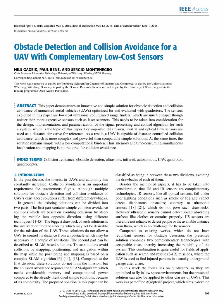
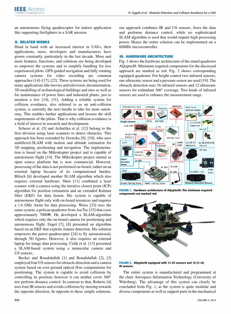
III. HARDWARE ARCHITECTUREFig. 1 shows the hardware architecture of the stated quadrotorAQopterI8. Minimum required components for the discussedapproach are marked as red. Fig. 2 shows correspondingequipped quadrotor. For height control two infrared sensors,one ultrasonic sensor and a pressure sensor are used [19]. Theobstacle detection uses 16 infrared sensors and 12 ultrasonicsensors for redundant 360◦ coverage. Two kinds of infraredsensors are used to enhance the measurement range.
FIGURE 1. Hardware architecture of AQopterI8: The minimum requiredcomponents are marked red.
FIGURE 2. AQopterI8 equipped with 12 US sensors and 16 (2×8)IR sensors.
The entire system is manufactured and programmed atthe chair Aerospace Information Technology (University ofWürzburg). The advantage of this system can clearly beconcluded from Fig. 1, as the system is quite modular anddiverse components as well as support parts in the mechanical
600 VOLUME 3, 2015
N. Gageik et al.: Obstacle Detection and Collision Avoidance for a UAV
design can easily be adapted to the requirements.The overall system design supports many components like
anAMD1.6GHz processor and cameras for image processinge.g., object detection, stereo vision and Fouriertracking [27]–[30].
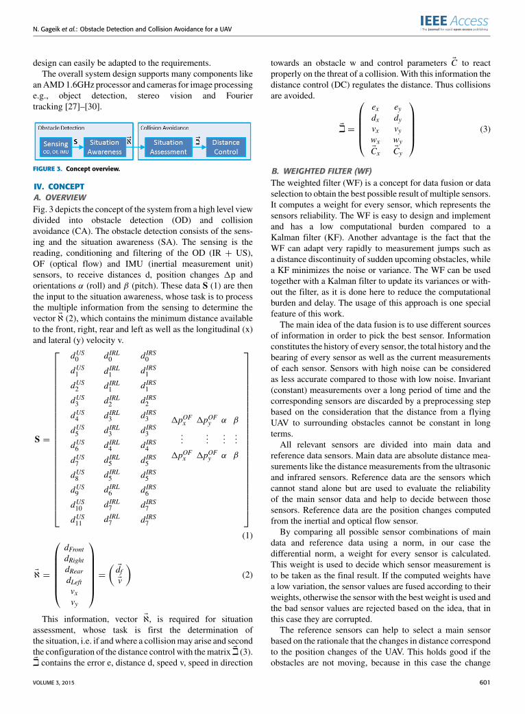
FIGURE 3. Concept overview.
IV. CONCEPTA. OVERVIEWFig. 3 depicts the concept of the system from a high level viewdivided into obstacle detection (OD) and collisionavoidance (CA). The obstacle detection consists of the sens-ing and the situation awareness (SA). The sensing is thereading, conditioning and filtering of the OD (IR + US),OF (optical flow) and IMU (inertial measurement unit)sensors, to receive distances d, position changes 1p andorientations α (roll) and β (pitch). These data S (1) are thenthe input to the situation awareness, whose task is to processthe multiple information from the sensing to determine thevector Eℵ (2), which contains the minimum distance availableto the front, right, rear and left as well as the longitudinal (x)and lateral (y) velocity v.
S =
dUS0 d IRL0
dUS1
dUS2
dUS3
dUS4
dUS5
dUS6
dUS7
dUS8
dUS9
dUS10
dUS11
d IRL1
d IRL1
d IRL2
d IRL3
d IRL3
d IRL4
d IRL5
d IRL5
d IRL6
d IRL7
d IRL7
d IRS0
d IRS1
d IRS1
d IRS2
d IRS3
d IRS3
d IRS4
d IRS5
d IRS5
d IRS6
d IRS7
d IRS7
1pOFx 1pOFy α
......
...
1pOFx 1pOFy α
β
...
β
(1)
Eℵ =
dFrontdRightdReardLeftvxvy
=(EdfEv
)(2)
This information, vector Eℵ, is required for situationassessment, whose task is first the determination ofthe situation, i.e. if andwhere a collisionmay arise and secondthe configuration of the distance control with thematrix Ei (3).Ei contains the error e, distance d, speed v, speed in direction
towards an obstacle w and control parameters EC to reactproperly on the threat of a collision. With this information thedistance control (DC) regulates the distance. Thus collisionsare avoided.
Ei =
exdxvxwxECx
eydyvywyECy
(3)
B. WEIGHTED FILTER (WF)The weighted filter (WF) is a concept for data fusion or dataselection to obtain the best possible result of multiple sensors.It computes a weight for every sensor, which represents thesensors reliability. The WF is easy to design and implementand has a low computational burden compared to aKalman filter (KF). Another advantage is the fact that theWF can adapt very rapidly to measurement jumps such asa distance discontinuity of sudden upcoming obstacles, whilea KF minimizes the noise or variance. The WF can be usedtogether with a Kalman filter to update its variances or with-out the filter, as it is done here to reduce the computationalburden and delay. The usage of this approach is one specialfeature of this work.The main idea of the data fusion is to use different sources
of information in order to pick the best sensor. Informationconstitutes the history of every sensor, the total history and thebearing of every sensor as well as the current measurementsof each sensor. Sensors with high noise can be consideredas less accurate compared to those with low noise. Invariant(constant) measurements over a long period of time and thecorresponding sensors are discarded by a preprocessing stepbased on the consideration that the distance from a flyingUAV to surrounding obstacles cannot be constant in longterms.All relevant sensors are divided into main data and
reference data sensors. Main data are absolute distance mea-surements like the distance measurements from the ultrasonicand infrared sensors. Reference data are the sensors whichcannot stand alone but are used to evaluate the reliabilityof the main sensor data and help to decide between thosesensors. Reference data are the position changes computedfrom the inertial and optical flow sensor.By comparing all possible sensor combinations of main
data and reference data using a norm, in our case thedifferential norm, a weight for every sensor is calculated.This weight is used to decide which sensor measurement isto be taken as the final result. If the computed weights havea low variation, the sensor values are fused according to theirweights, otherwise the sensor with the best weight is used andthe bad sensor values are rejected based on the idea, that inthis case they are corrupted.The reference sensors can help to select a main sensor
based on the rationale that the changes in distance correspondto the position changes of the UAV. This holds good if theobstacles are not moving, because in this case the change
VOLUME 3, 2015 601
N. Gageik et al.: Obstacle Detection and Collision Avoidance for a UAV
of distances from the obstacles and the position changes ofthe UAV are equal. If the obstacles are moving, this informa-tion is corrupted by their movement, but still it is unlikelythat this movement corresponds better to randomly wrongmeasurements. However, this problem can be handled byparametrization of the WF.
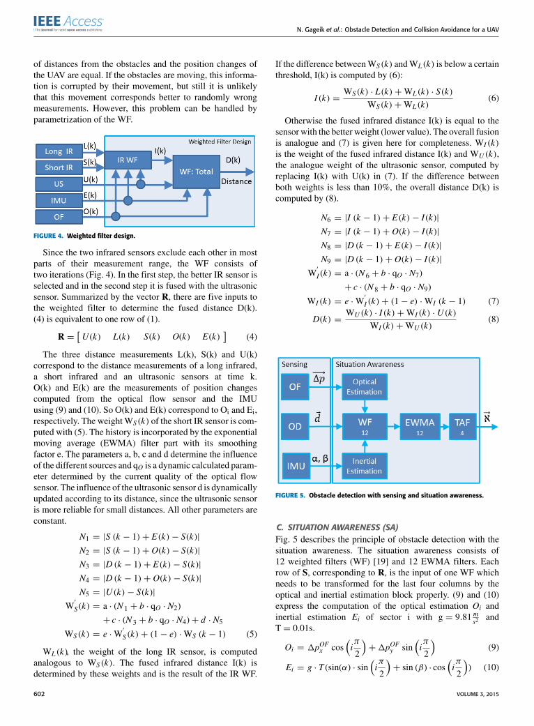
FIGURE 4. Weighted filter design.
Since the two infrared sensors exclude each other in mostparts of their measurement range, the WF consists oftwo iterations (Fig. 4). In the first step, the better IR sensor isselected and in the second step it is fused with the ultrasonicsensor. Summarized by the vector R, there are five inputs tothe weighted filter to determine the fused distance D(k).(4) is equivalent to one row of (1).
R =[U (k) L(k) S(k) O(k) E(k)
](4)
The three distance measurements L(k), S(k) and U(k)correspond to the distance measurements of a long infrared,a short infrared and an ultrasonic sensors at time k.O(k) and E(k) are the measurements of position changescomputed from the optical flow sensor and the IMUusing (9) and (10). So O(k) and E(k) correspond to Oi and Ei,respectively. The weightWS(k) of the short IR sensor is com-puted with (5). The history is incorporated by the exponentialmoving average (EWMA) filter part with its smoothingfactor e. The parameters a, b, c and d determine the influenceof the different sources and qO is a dynamic calculated param-eter determined by the current quality of the optical flowsensor. The influence of the ultrasonic sensor d is dynamicallyupdated according to its distance, since the ultrasonic sensoris more reliable for small distances. All other parameters areconstant.
N1 = |S (k − 1)+ E(k)− S(k)|
N2 = |S (k − 1)+ O(k)− S(k)|
N3 = |D (k − 1)+ E(k)− S(k)|
N4 = |D (k − 1)+ O(k)− S(k)|
N5 = |U(k)− S(k)|
W′
S (k) = a · (N 1 + b · qO · N2)
+ c · (N 3 + b · qO · N4)+ d · N5
WS(k) = e ·W′
S(k)+ (1− e) ·WS (k − 1) (5)
WL(k), the weight of the long IR sensor, is computedanalogous to WS(k). The fused infrared distance I(k) isdetermined by these weights and is the result of the IR WF.
If the difference betweenWS(k) andWL(k) is below a certainthreshold, I(k) is computed by (6):
I (k) =WS(k) · L(k)+WL(k) · S(k)
WS(k)+WL(k)(6)
Otherwise the fused infrared distance I(k) is equal to thesensor with the better weight (lower value). The overall fusionis analogue and (7) is given here for completeness. WI (k)is the weight of the fused infrared distance I(k) and WU (k),the analogue weight of the ultrasonic sensor, computed byreplacing I(k) with U(k) in (7). If the difference betweenboth weights is less than 10%, the overall distance D(k) iscomputed by (8).
N6 = |I (k − 1)+ E(k)− I (k)|
N7 = |I (k − 1)+ O(k)− I (k)|
N8 = |D (k − 1)+ E(k)− I (k)|
N9 = |D (k − 1)+ O(k)− I (k)|
W′
I (k) = a · (N 6 + b · qO · N7)
+ c · (N 8 + b · qO · N9)
WI (k) = e ·W′
I (k)+ (1− e) ·WI (k − 1) (7)
D(k) =WU (k) · I (k)+WI (k) · U(k)
WI (k)+WU (k)(8)
FIGURE 5. Obstacle detection with sensing and situation awareness.
C. SITUATION AWARENESS (SA)Fig. 5 describes the principle of obstacle detection with thesituation awareness. The situation awareness consists of12 weighted filters (WF) [19] and 12 EWMA filters. Eachrow of S, corresponding to R, is the input of one WF whichneeds to be transformed for the last four columns by theoptical and inertial estimation block properly. (9) and (10)express the computation of the optical estimation Oi andinertial estimation Ei of sector i with g = 9.81 m
s2and
T = 0.01s.
Oi = 1pOFx cos(iπ
2
)+1pOFy sin
(iπ
2
)(9)
Ei = g · T (sin(α) · sin(iπ
2
)+ sin (β) · cos
(iπ
2
)) (10)
602 VOLUME 3, 2015

N. Gageik et al.: Obstacle Detection and Collision Avoidance for a UAV
Algorithm 1 TAFInput: distance main neighbor left: mlInput: distance direct neighbor left: nlInput: distance main: mInput: distance direct neighbor right: nrInput: distance main neighbor right: mrInput: tolerance: τSavings: last weights: w0,w1,w2Output: fused minimum distance: dif (ml < nl · τ ) then nl=∞ end ifif (mr < nr · τ ) then nr = ∞ end ifif (m < nl) then
if (m < nr ) then w0 = 0else w0 = 1end if
elseif (nl < nr ) then w0 = −1else w0 = 1end if
end ifS=
∑iwi
w2 = w1w1 = w0d = mif (S < −1) then d = nl end ifif (S > 1) then d = nr end ifreturn d
The outputs of the WF or EWMA are 12 filtereddistances of available place around the quadrotor, which canbe described by 12 sectors (Fig. 5). The EWMA is used toreduce noise.
The velocity vector Ev, one part of vector Eℵ, is computed bythe derivation of the corresponding lowest distance from thevector Edf . If the derivative is under a certain threshold, it is setto zero to dismiss jumps from noisy measurements or obsta-cles which do not correspond to a movement. The derivativesare then filtered with a EWMA filter. The accuracy of thevelocity vector Ev can be improved by the usage of the opticalflow sensor. Since the system should also be operable incase of bad lighting conditions, when the OF sensor fails,the vector Ev does not rely on the OF data. An integration ofthe IMU with a complementary filter for velocity estimationdid not lead to better results and therefore has not been used.The proposed approach showed good results for velocityestimation.
T =
E9E11E0E1E3
E0E2E3E4E6
E3E5E6E7E9
E6E8E9E10E0
(11)
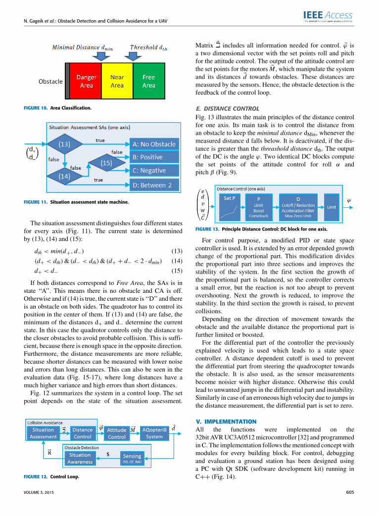
The task of the triple awareness fusion (TAF) is todetermine the four distances Edf (2) as one fundamental base
for the situation assessment. The idea is to reduce the12 outputs of the EWMA Ei to 4 inputs, which can beprocessed by the collision avoidance. It is called ‘‘triple’’,because it always fuses three sectors to one common sector(Fig. 8). Each column of T is the input to a single TAFfilter (11).
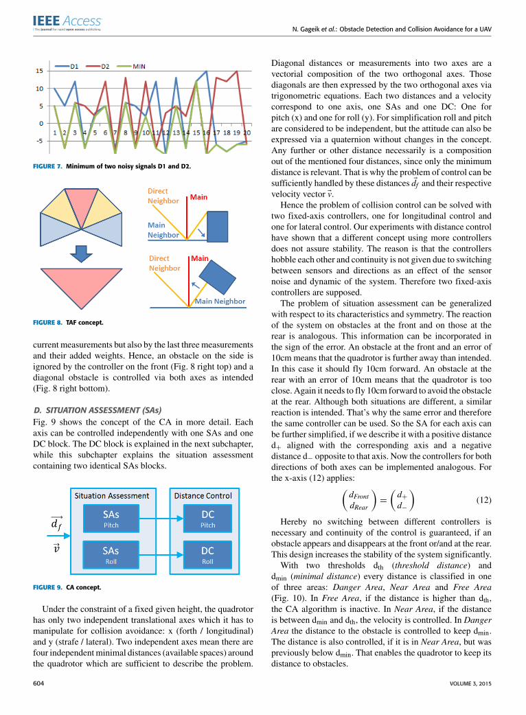
The TAF algorithm picks the minimum relevant distance asthe available space into the respective direction. There aretwo reasons for why a simple min() function is not sufficient.The first reason is the noise. The minimum of two noisysignals is significantly lower than each single signal or theiraverage. The example data of Fig. 7 show that the average ofD1 is 2.25 and the average of D2 is 3.6, but the average oftheir minimum is −2.25. This effect, if not considered, leadsto large errors.
That is why the TAF algorithm not only considers thecurrent measurement, but also the last two measurements,without the drawback of a delay. This information is storedin the last weights w1,w2. These weights together with thecurrent weight w0 determine the current result.The second effect, which needs to be taken into
consideration, can be explained as data dependency.An obstacle located on one axis may move through the datafusion unintentionally into another axis. This is the case,because transversal sensors measure two axes. For examplea wall on the right is measured by US sensor 3 (dUS3 )(Fig. 6), but also by number 1 (dUS1 ). If we would compute thefront distance only with min(dUS11 , d
US0 , d
US1 ), the wall on the
right would move to the front leading to erroneous results.To solve this problem, the TAF algorithm discards thosemeasurements, when the corresponding neighbor issmaller because in that case the obstacle belongs to theother axis.
FIGURE 6. Left: 12 sectors around the quadrotor (WF + EWMA output):Correspondents to the position of the 12 US sensors dUS
0 · · · dUS11
Right: 8 sectors around the quadrotor representing the 2×8 IR sensors.
The concept of the TAF can be visualized best in Fig. 8.The five inputs are the straight main distance (red), the directneighbor distances left and right (yellow) and the main neigh-bor distances left and right (blue). Now, a direct neighbor isdiscarded (set to infinity), if the corresponding main neighboris smaller. In the next step of the TAF algorithm the minimumvalue is picked between the sensor measurement of the mainand direct neighbors. This is not only determined by the
VOLUME 3, 2015 603
N. Gageik et al.: Obstacle Detection and Collision Avoidance for a UAV
FIGURE 7. Minimum of two noisy signals D1 and D2.
FIGURE 8. TAF concept.
current measurements but also by the last three measurementsand their added weights. Hence, an obstacle on the side isignored by the controller on the front (Fig. 8 right top) and adiagonal obstacle is controlled via both axes as intended(Fig. 8 right bottom).
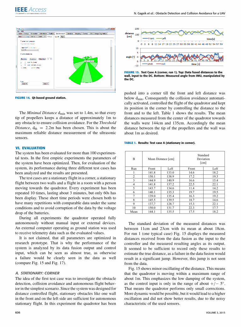
D. SITUATION ASSESSMENT (SAs)Fig. 9 shows the concept of the CA in more detail. Eachaxis can be controlled independently with one SAs and oneDC block. The DC block is explained in the next subchapter,while this subchapter explains the situation assessmentcontaining two identical SAs blocks.
FIGURE 9. CA concept.
Under the constraint of a fixed given height, the quadrotorhas only two independent translational axes which it has tomanipulate for collision avoidance: x (forth / longitudinal)and y (strafe / lateral). Two independent axes mean there arefour independentminimal distances (available spaces) aroundthe quadrotor which are sufficient to describe the problem.
Diagonal distances or measurements into two axes are avectorial composition of the two orthogonal axes. Thosediagonals are then expressed by the two orthogonal axes viatrigonometric equations. Each two distances and a velocitycorrespond to one axis, one SAs and one DC: One forpitch (x) and one for roll (y). For simplification roll and pitchare considered to be independent, but the attitude can also beexpressed via a quaternion without changes in the concept.Any further or other distance necessarily is a compositionout of the mentioned four distances, since only the minimumdistance is relevant. That is why the problem of control can besufficiently handled by these distances Edf and their respectivevelocity vector Ev.
Hence the problem of collision control can be solved withtwo fixed-axis controllers, one for longitudinal control andone for lateral control. Our experiments with distance controlhave shown that a different concept using more controllersdoes not assure stability. The reason is that the controllershobble each other and continuity is not given due to switchingbetween sensors and directions as an effect of the sensornoise and dynamic of the system. Therefore two fixed-axiscontrollers are supposed.
The problem of situation assessment can be generalizedwith respect to its characteristics and symmetry. The reactionof the system on obstacles at the front and on those at therear is analogous. This information can be incorporated inthe sign of the error. An obstacle at the front and an error of10cm means that the quadrotor is further away than intended.In this case it should fly 10cm forward. An obstacle at therear with an error of 10cm means that the quadrotor is tooclose. Again it needs to fly 10cm forward to avoid the obstacleat the rear. Although both situations are different, a similarreaction is intended. That’s why the same error and thereforethe same controller can be used. So the SA for each axis canbe further simplified, if we describe it with a positive distanced+ aligned with the corresponding axis and a negativedistance d− opposite to that axis. Now the controllers for bothdirections of both axes can be implemented analogous. Forthe x-axis (12) applies:(
dFrontdRear
)=
(d+d−
)(12)
Hereby no switching between different controllers isnecessary and continuity of the control is guaranteed, if anobstacle appears and disappears at the front or/and at the rear.This design increases the stability of the system significantly.
With two thresholds dth (threshold distance) anddmin (minimal distance) every distance is classified in oneof three areas: Danger Area, Near Area and Free Area(Fig. 10). In Free Area, if the distance is higher than dth,the CA algorithm is inactive. In Near Area, if the distanceis between dmin and dth, the velocity is controlled. In DangerArea the distance to the obstacle is controlled to keep dmin.The distance is also controlled, if it is in Near Area, but waspreviously below dmin. That enables the quadrotor to keep itsdistance to obstacles.
604 VOLUME 3, 2015
N. Gageik et al.: Obstacle Detection and Collision Avoidance for a UAV
FIGURE 10. Area Classification.
FIGURE 11. Situation assessment state machine.
The situation assessment distinguishes four different statesfor every axis (Fig. 11). The current state is determinedby (13), (14) and (15):
dth < min(d+, d−) (13)
(d+ < dth)& (d− < dth)& (d+ + d− < 2 · dmin) (14)
d+ < d− (15)
If both distances correspond to Free Area, the SAs is instate ‘‘A’’. This means there is no obstacle and CA is off.Otherwise and if (14) is true, the current state is ‘‘D’’ and thereis an obstacle on both sides. The quadrotor has to control itsposition in the center of them. If (13) and (14) are false, theminimum of the distances d+ and d− determine the currentstate. In this case the quadrotor controls only the distance tothe closer obstacles to avoid probable collision. This is suffi-cient, because there is enough space in the opposite direction.Furthermore, the distance measurements are more reliable,because shorter distances can be measured with lower noiseand errors than long distances. This can also be seen in theevaluation data (Fig. 15-17), where long distances have amuch higher variance and high errors than short distances.
Fig. 12 summarizes the system in a control loop. The setpoint depends on the state of the situation assessment.
FIGURE 12. Control Loop.
Matrix Ei includes all information needed for control. Eϕ isa two dimensional vector with the set points roll and pitchfor the attitude control. The output of the attitude control arethe set points for the motors EM , which manipulate the systemand its distances Ed towards obstacles. These distances aremeasured by the sensors. Hence, the obstacle detection is thefeedback of the control loop.
E. DISTANCE CONTROLFig. 13 illustrates the main principles of the distance controlfor one axis. Its main task is to control the distance froman obstacle to keep the minimal distance dMin, whenever themeasured distance d falls below. It is deactivated, if the dis-tance is greater than the threashold distance dth. The outputof the DC is the angle ϕ. Two identical DC blocks computethe set points of the attitude control for roll α andpitch β (Fig. 9).
FIGURE 13. Principle Distance Control: DC block for one axis.
For control purpose, a modified PID or state spacecontroller is used. It is extended by an error depended growthchange of the proportional part. This modification dividesthe proportional part into three sections and improves thestability of the system. In the first section the growth ofthe proportional part is balanced, so the controller correctsa small error, but the reaction is not too abrupt to preventovershooting. Next the growth is reduced, to improve thestability. In the third section the growth is raised, to preventcollisions.
Depending on the direction of movement towards theobstacle and the available distance the proportional part isfurther limited or boosted.
For the differential part of the controller the previouslyexplained velocity is used which leads to a state spacecontroller. A distance dependent cutoff is used to preventthe differential part from steering the quadrocopter towardsthe obstacle. It is also used, as the sensor measurementsbecome noisier with higher distance. Otherwise this couldlead to unwanted jumps in the differential part and instability.Similarly in case of an erroneous high velocity due to jumps inthe distance measurement, the differential part is set to zero.
V. IMPLEMENTATIONAll the functions were implemented on the32bit AVRUC3A0512microcontroller [32] and programmedin C. The implementation follows thementioned concept withmodules for every building block. For control, debuggingand evaluation a ground station has been designed usinga PC with Qt SDK (software development kit) running inC++ (Fig. 14).
VOLUME 3, 2015 605
N. Gageik et al.: Obstacle Detection and Collision Avoidance for a UAV
FIGURE 14. Qt-based ground station.
The Minimal Distance dmin was set to 1.4m, so that everytip of propellers keeps a distance of approximately 1m toany obstacle to ensure collision avoidance. For the ThresholdDistance, dth = 2.2m has been chosen. This is about themaximum reliable distance measurement of the ultrasonicsensors.
VI. EVALUATIONThe system has been evaluated for more than 100 experimen-tal tests. In the first empiric experiments the parameters ofthe system have been optimized. Then, for evaluation of thesystem, its performance during three different test cases hasbeen analyzed and the results are presented.
The test cases are a stationary flight in a corner, a stationaryflight between two walls and a flight in a room with a personmoving towards the quadrotor. Every experiment has beenrepeated 10 times, lasting about 3 minutes, but only 60s hasbeen display. These short time periods were chosen both tohave many repetitions with comparable data under the sameconditions and to avoid corruption of the data by the voltagedrop of the batteries.
During all experiments the quadrotor operated fullyautonomously without manual input or external devices.An external computer operating as ground station was usedto receive telemetry data such as the evaluated values.
It is not claimed, that all parameters are optimized inresearch prototype. That is why the performance of thesystem is analyzed by its data fusion output and controlinput, which can be seen as almost true, as otherwisea failure would be clearly seen in the data as well(compare Fig. 15 and Fig. 17).
A. STATIONARY: CORNERThe idea of the first test case was to investigate the obstacledetection, collision avoidance and autonomous flight behav-ior in the simplest scenario. Since the systemwas designed fordistance controlled flight, stationary obstacles like one wallin the front and on the left side are sufficient for autonomousstationary flight. In this experiment the quadrotor has been
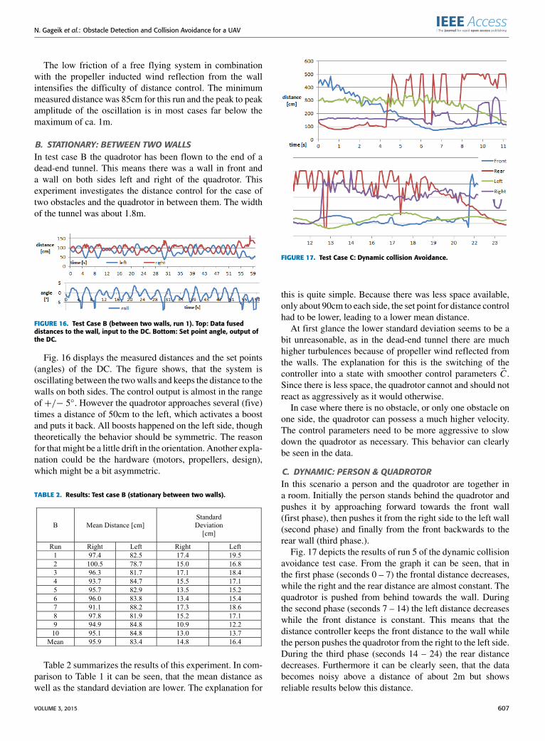
FIGURE 15. Test Case A (corner, run 1). Top: Data fused distances to thewall, input to the DC. Bottom: Measured angle from IMU, manipulated bythe DC.
pushed into a corner till the front and left distance wasbelow dmin. Consequently the collision avoidance automati-cally activated, controlled the flight of the quadrotor and keptits position in the corner by controlling the distance to thefront and to the left. Table 1 shows the results. The meandistances measured from the center of the quadrotor towardsthe walls were 144cm and 135cm. Accordingly the meandistance between the tip of the propellers and the wall wasabout 1m as desired.
TABLE 1. Results: Test case A (stationary in corner).
The standard deviation of the measured distances wasbetween 11cm and 23cm with its mean at about 18cm.For run 1 (one typical case) Fig. 15 displays the measureddistances received from the data fusion as the input to thecontroller and the measured resulting angles as its output.It seemed to be sufficient to record only these results toestimate the true distance, as a failure in the data fusion wouldresult in a significant jump. However, this jump is not seenfrom the data.
Fig. 15 showsminor oscillating of the distance. This meansthat the quadrotor is moving within a maximum range ofabout 1m. This emphasizes the low damping of the system,as the control input is only in the range of about +/− 5◦.That means the quadrotor performs only small corrections.More dynamicwould be possible, but it would lead to a higheroscillation and did not show better results, due to the noisycharacteristic of the used sensors.
606 VOLUME 3, 2015
N. Gageik et al.: Obstacle Detection and Collision Avoidance for a UAV
The low friction of a free flying system in combinationwith the propeller inducted wind reflection from the wallintensifies the difficulty of distance control. The minimummeasured distance was 85cm for this run and the peak to peakamplitude of the oscillation is in most cases far below themaximum of ca. 1m.
B. STATIONARY: BETWEEN TWO WALLSIn test case B the quadrotor has been flown to the end of adead-end tunnel. This means there was a wall in front anda wall on both sides left and right of the quadrotor. Thisexperiment investigates the distance control for the case oftwo obstacles and the quadrotor in between them. The widthof the tunnel was about 1.8m.
FIGURE 16. Test Case B (between two walls, run 1). Top: Data fuseddistances to the wall, input to the DC. Bottom: Set point angle, output ofthe DC.
Fig. 16 displays the measured distances and the set points(angles) of the DC. The figure shows, that the system isoscillating between the twowalls and keeps the distance to thewalls on both sides. The control output is almost in the rangeof +/− 5◦. However the quadrotor approaches several (five)times a distance of 50cm to the left, which activates a boostand puts it back. All boosts happened on the left side, thoughtheoretically the behavior should be symmetric. The reasonfor that might be a little drift in the orientation. Another expla-nation could be the hardware (motors, propellers, design),which might be a bit asymmetric.
TABLE 2. Results: Test case B (stationary between two walls).
Table 2 summarizes the results of this experiment. In com-parison to Table 1 it can be seen, that the mean distance aswell as the standard deviation are lower. The explanation for
FIGURE 17. Test Case C: Dynamic collision Avoidance.
this is quite simple. Because there was less space available,only about 90cm to each side, the set point for distance controlhad to be lower, leading to a lower mean distance.
At first glance the lower standard deviation seems to be abit unreasonable, as in the dead-end tunnel there are muchhigher turbulences because of propeller wind reflected fromthe walls. The explanation for this is the switching of thecontroller into a state with smoother control parameters EC .Since there is less space, the quadrotor cannot and should notreact as aggressively as it would otherwise.
In case where there is no obstacle, or only one obstacle onone side, the quadrotor can possess a much higher velocity.The control parameters need to be more aggressive to slowdown the quadrotor as necessary. This behavior can clearlybe seen in the data.
C. DYNAMIC: PERSON & QUADROTORIn this scenario a person and the quadrotor are together ina room. Initially the person stands behind the quadrotor andpushes it by approaching forward towards the front wall(first phase), then pushes it from the right side to the left wall(second phase) and finally from the front backwards to therear wall (third phase.).
Fig. 17 depicts the results of run 5 of the dynamic collisionavoidance test case. From the graph it can be seen, that inthe first phase (seconds 0 – 7) the frontal distance decreases,while the right and the rear distance are almost constant. Thequadrotor is pushed from behind towards the wall. Duringthe second phase (seconds 7 – 14) the left distance decreaseswhile the front distance is constant. This means that thedistance controller keeps the front distance to the wall whilethe person pushes the quadrotor from the right to the left side.During the third phase (seconds 14 – 24) the rear distancedecreases. Furthermore it can be clearly seen, that the databecomes noisy above a distance of about 2m but showsreliable results below this distance.
VOLUME 3, 2015 607

N. Gageik et al.: Obstacle Detection and Collision Avoidance for a UAV
This experiment demonstrates that the quadrotor is capableof autonomous flight with people in its environment andcan control its distance simultaneously to multiple obstaclesfrom multiple changing directions. The speed of the movingobstacle (person) in this experiment was about 1m/s.
VII. CONCLUSION AND FUTURE WORKThe evaluation shows that the demonstrated solution iscapable of autonomous flight and collision avoidance in mul-tiple scenarios. Amain contribution of this work is to disprovethe myth that only expensive sensors like laser scanner aresuitable for such a task and low-cost range finders are not.The evaluation showed that the system is capable to avoidcollisions with obstacles such as walls and people while itcan control its distance towards them.
In the previous work about distance controlled collisionavoidance and fully autonomous flight using ultrasonicsensors only [18], [20], it was not possible to avoid collisionswith persons, because the ultrasonic sensors failed to detectthem reliably. The present paper demonstrated a solution tothat limitation by fusing IR and US sensors.
Because the presented solution merges multiple low-costsensors of different technologies (infrared, ultrasonic), it ismore reliable and cheaper than state of the art solutions. Fur-thermore the presented approach is much easier to implementin case of mathematical complexity compared to existingapproaches, while keeping the computational burden low,reducing development and maintenance costs. To the best ofthe authors’ knowledge, no fully autonomous system exists,which is comparable in power.
The infrared sensors may be replaced by a low-cost laserscanner such as the RP Lidar. Such a solution would beslightly more reliable in case of better sensor coverage,however more expensive and heavier. A more powerful pro-cessor like an Intel Atomor theAMDT56Nmight be requiredin this case, which also increases costs and weight. Also thesample rate of the infrared sensors can be set higher comparedto the frequency of a scanner. Nevertheless the RPLidar couldbe a good improvement of the mentioned solution, whichneeds to be investigated in the future.
Another option for future work is the evaluation of theobstacle detection sensors by all sensors of the AQopterI8.This means the quadrotor would use besides the RP Lidaralso the SV (stereo vision) system and the PMD nano (pho-tonic mixing device). This can improve the performance andreliability of the system further, but it would also increase theweight and the costs of the system.
ACKNOWLEDGMENTThe authors would like to thank Thilo Müller,David Courtney and Qasim Ali for their contributions to thiswork.
REFERENCES[1] M. Becker, R. C. B. Sampaio, S. Bouabdallah, V. de Perrot, and
R. Siegwart, ‘‘In-flight collision avoidance controller based only on OS4embedded sensors,’’ J. Brazilian Soc. Mech. Sci. Eng., vol. 34, no. 3,pp. 294–307, Jul./Sep. 2012.
[2] S. Bouabdallah, ‘‘Design and control of quadrotors with application toautonomous flying,’’ Ph.D. dissertation, Faculte Sci. Techn. l’ingenieur,École Polytech. Fédérale Lausanne, Switzerland, 2007. [Online]. Avail-able: http://biblion.epfl.ch/EPFL/theses/2007/3727/EPFL_TH3727.pdf
[3] S. Bouabdallah, M. Becker, V. de Perrot, and R. Siegwart, ‘‘Towardobstacle avoidance on quadrotors,’’ in Proc. 12th Int. Symp. Dyn. ProblemsMech., Ilhabela, Brazil, 2007, pp. 1–10.
[4] J. F. Roberts, T. S. Stirling, J.-C. Zufferey, and D. Floreano, ‘‘Quadrotorusing minimal sensing for autonomous indoor flight,’’ in Proc. MAV, 2007,pp. 1–8.
[5] S. Scherer, S. Singh, L. Chamberlain, and M. Elgersma, ‘‘Flying fast andlow among obstacles: Methodology and experiments,’’ Int. J. Robot. Res.,vol. 27, no. 5, pp. 549–574, 2008.
[6] M. Blösch, S.Weiss, D. Scaramuzza, and R. Siegwart, ‘‘Vision basedMAVnavigation in unknown and unstructured environments,’’ in Proc. IEEE Int.Conf. Robot. Autom. (ICRA), Anchorage, AK, USA, May 2010, pp. 21–28.
[7] J. Engel, J. Sturm, and D. Cremers, ‘‘Accurate figure flying witha quadrocopter using onboard visual and inertial sensing,’’ in Proc. IEEEInt. Conf. Intell. Robot Syst., Oct. 2012.
[8] J. Engel, J. Sturm, and D. Cremers, ‘‘Camera-based navigation of a low-cost quadrocopter,’’ in Proc. IEEE/RSJ Int. Conf. Intell. Robots Syst.,Oct. 2012, pp. 2815–2821.
[9] S. Gronzka, ‘‘Mapping, state estimation, and navigation for quadrotorsand human-worn sensor systems,’’ Ph.D. dissertation, Technische Fakultät,Albert-Ludwigs-Univ. Freiburg, Breisgau, Germany, 2011.
[10] S. Grzonka, G. Grisetti, and W. Burgard, ‘‘A fully autonomous indoorquadrotor,’’ IEEE Trans. Robot., vol. 28, no. 1, pp. 90–100, Feb. 2012.
[11] S. Shen, N. Michael, and V. Kumar, ‘‘Autonomous multi-floor indoornavigation with a computationally constrained MAV,’’ in Proc. IEEE Int.Conf. Robot. Autom., Shanghai, China, May 2011, pp. 20–25.
[12] M. Achtelik, A. Bachrach, R. He, S. Prentice, and N. Roy, ‘‘Autonomousnavigation and exploration of a quadrotor helicopter in GPS-denied indoor environments,’’ in Proc. 1st Symp. Indoor Flight,2008. [Online]. Available: http://robot-chopper.googlecode.com/svn-history/r479/trunk/References/2009MIT.pdf
[13] K. Celik, S.-J. Chung,M. Clausman, andA. K. Somani, ‘‘Monocular visionSLAM for indoor aerial vehicles,’’ in Proc. IEEE/RSJ Int. Conf. Intell.Robots Syst., Oct. 2009, pp. 1566–1573.
[14] MikroKopter. (Jan. 1, 2015). [Online]. Available: http://www.mikrokopter.de/
[15] AscTec. (Jan. 15, 2015). [Online]. Available: http://www.asctec.de/[16] Aibotix. (Jan. 15, 2015). [Online]. Available: http://www.aibotix.de/[17] Microdrones. (Jan. 15, 2015). [Online]. Available: http://www.
microdrones.de/[18] N. Gageik, T. Müller, and S. Montenegro, ‘‘Obstacle detection and col-
lision avoidance using ultrasonic distance sensors for an autonomousquadrocopter,’’ in Proc. UAVveek Workshop Contrib., 2012.
[19] N. Gageik, J. Rothe, and S. Montenegro, ‘‘Data fusion principles for heightcontrol and autonomous landing of a quadrocopter,’’ in Proc. UAVveekWorkshop Contrib., 2012.
[20] T. Müller, ‘‘Implementierung und evaluierung eines systems zur hin-derniserkennung und kollisionsvermeidung für indoor-quadrokopter,’’diploma thesis, Aerosp. Inf. Technol., Univ. Würzburg, Germany, 2011.
[21] J. Rothe, ‘‘Implementierung und evaluierung einer höhenregelung füreinen quadrokopter,’’ bachelor thesis, Aerosp. Inf. Technol., Univ.Würzburg, Germany, 2012.
[22] G. Hoffmann, D. G. Rajnarayan, S. L. Waslander, D. Dostal, J. S. Jang, andC. J. Tomlin, ‘‘The Stanford testbed of autonomous rotorcraft for multiagent control (STARMAC),’’ in Proc. 23rd Digit. Avionics Syst. Conf.,Oct. 2004, pp. 12.E.4-1–12.E.4-10.
[23] S. Weiss, D. Scaramuzza, and R. Siegwart, ‘‘Monocular-SLAM–basednavigation for autonomous micro helicopters in GPS-denied environ-ments,’’ J. Field Robot., vol. 28, no. 6, pp. 854–874, 2011.
[24] Parrot. (Jan. 15, 2015). [Online]. Available: http://www.parrot.com[25] K. Nonami, F. Kendoul, S. Suzuki, W. Wang, and D. Nakazawa,
Autonomous Flying Robots. Tokyo, Japan: Springer-Verlag, 2010.[26] R. Brockers, M. Hummenberger, S. Weiss, and L. Matthies, ‘‘Towards
autonomous navigation of miniature UAV,’’ in Proc. IEEE Conf. Comput.Vis. Pattern Recognit. Workshops (CVPRW), Jun. 2014, pp. 645–651.
[27] H. A. Lauterbach and D.-I. N. Gageik, ‘‘Stereo-optische abstandsmessungfür einen autonomen quadrocopter,’’ bachelor thesis, Aerosp. Inf. Technol.,Univ. Würzburg, Germany, 2013.
608 VOLUME 3, 2015
N. Gageik et al.: Obstacle Detection and Collision Avoidance for a UAV
[28] E. Reinthal and D.-I. N. Gageik, ‘‘Positionsbestimmung eines autonomenquadrokopters durch bildverarbeitung,’’ bachelor thesis, Aerosp. Inf. Tech-nol., Univ. Würzburg, Germany, 2013.
[29] N. Gageik, C. Reul, and S. Montenegro, ‘‘Autonomous quadrocopter forsearch, count and localization of objects,’’ in Proc. UAVWorld Conf., 2013.
[30] N. Gageik, E. Reinthal, P. Benz, and S. Montenegro, ‘‘Complementaryvision based data fusion for robust positioning and directed flight of anautonomous quadrocopter,’’ Int. J. Artif. Intell. Appl., vol. 5, no. 5, 2014.
[31] G. Verhoeven, ‘‘Using theMD4-1000 in archaeological research,’’ in Proc.UAVveek Workshop Contrib. 2012.
[32] Atmel. (Mar. 2015). [Online]. Available: http://www.atmel.com
NILS GAGEIK was born in Aachen, Germany,in 1982. He received the Diploma (Dipl.-Ing., oldGerman master) degree in computer engineeringfrom RWTH Aachen University, in 2010. He iscurrently pursuing the Ph.D. degree in computerscience with the University of Würzburg,Germany.
He has been a Research Assistant with theDepartment of Aerospace Information Technol-ogy, University of Würzburg, since 2010. Besides
teaching, he is involved in research on autonomous quadrotors. He leadsthe AQopterI8 Project, which aims to research and develop autonomousquadrocopters for indoor applications. He won the University PromotionPrize for his work in 2014.
PAUL BENZ was born in Aschaffenburg,Germany, in 1990. He received the B.Sc. degreein aerospace computer science from the Universityof Würzburg, in 2013. He is currently pursuing theM.Sc. degree in computer science.
He participated as a member of the AQopterI8Project in the field of obstacle detection and colli-sion, during his bachelor’s thesis and an internship.Since 2014, he has been a Student Assistant withthe Department of Aerospace Information
Technology.
SERGIO MONTENEGRO was born in Guatemalain 1959. He received the B.S. degree from the Uni-versidad del Valle, in 1982, and the M.S. degree incomputer science and the Ph.D. degree from theTechnical University of Berlin, in 1985 and 1989,respectively.
He was a Research Assistant in DistributedComputing with the Fraunhofer-GesellschaftInstitut, Berlin, from 1985 to 2007. From2007 to 2010, he was the Leader with the Depart-
ment of Central Avionic Systems, DLR, Bremen. Since 2010, he has beena Professor and the Chair of the Department of Aerospace InformationTechnology with the University of Würzbug, Germany.
VOLUME 3, 2015 609