obstacle detection with a sequence of ultra telephoto ... · obstacle detection with a sequence of...
TRANSCRIPT
Obstacle detection with a sequence of ultra telephoto camera images
M. Ukai Signalling Systems, Railway Technical Research Institute, Japan
Abstract
In order to detect obstacles on railway tracks, we have developed a forward monitoring system, which plays an important role to ensure the safety of train operation. In this paper, we propose a method of detecting obstacles with an image sequence taken by an ultra telephoto lens camera mounted on train which monitors the status of the track for 600m (brake distance) or over ahead of the train. We first discussed the railway track environment recognition. Particularly extraction of two parallel rails is a fundamental issue in applying image processing to railways. It is inevitable to limit the area where obstacles exist. A first detection algorithm is based on the analysis of optical flow which characteristically occurs in those moving obstacles. Assuming that pixels corresponding to the same object have similar flow vectors, we extract a connected region with similar flow vectors. Then we focused on the stationary obstacle edge and the brightness contrast difference from the background. Compensation for the flow field caused by camera blur was performed, so that our method works correctly even on running trains. Furthermore, we adopted a vibration-proofing device to reduce blurs of image, and a wide dynamic range camera so as not to be influenced by fluctuations such as outdoor lighting inconsistency. The experimental results using a real image sequence proves the effectiveness of our proposed method. Keywords: safety monitoring, obstacle detection, sequence of image processing, machine visions.
1 Introduction
Analysis of traffic environment has recently been an important topic as the interest in traffic safety increases. In the field of automobiles, research and
Computers in Railways IX, J. Allan, C. A. Brebbia, R. J. Hill, G. Sciutto & S. Sone (Editors)© 2004 WIT Press, www.witpress.com, ISBN 1-85312-715-9
development have been conducted on the forward surveillance system. The method to use supersonic waves, laser radars, infrared rays, etc. as forward surveillance sensors are classified as an active method, which is now being put to practical use. However, its application is limited to sufficiently large objects that correctly reflect laser beans. There are also problems of interference and insufficient spatial resolution. On the other hand, image recognition (machine vision) is a typical example of passive method. An advantage of the machine vision is that it sometimes detects a rail, person and car etc. at a high spatial resolution. Vision-based techniques can detect track, classify and identify obstacles.
2 Spatial railway field recognition
2.1 Optical arrangement
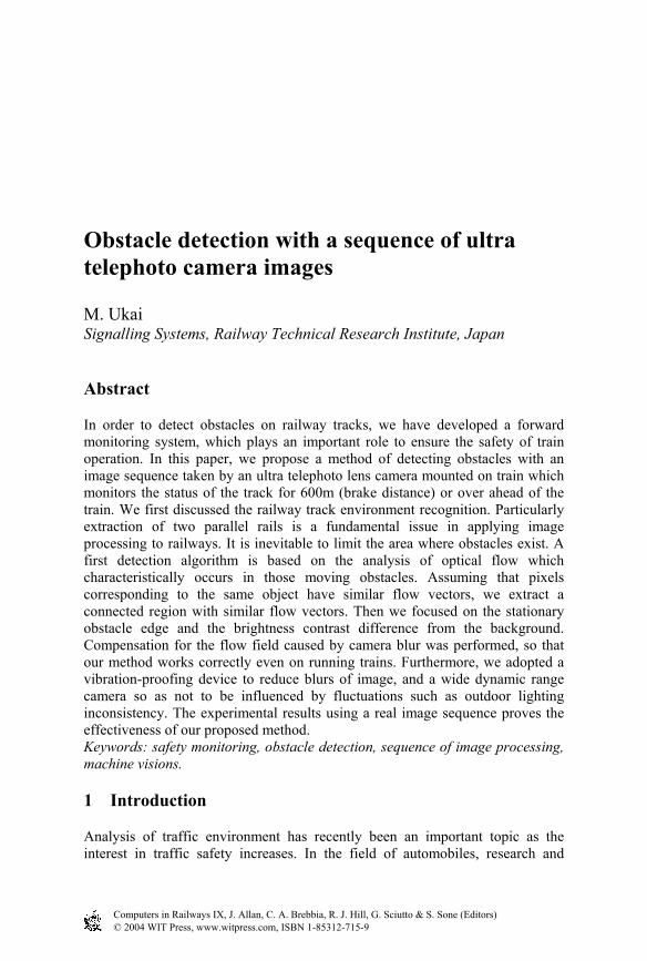
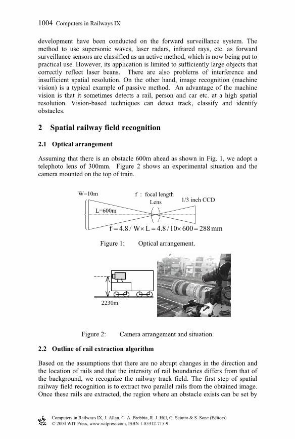
Assuming that there is an obstacle 600m ahead as shown in Fig. 1, we adopt a telephoto lens of 300mm. Figure 2 shows an experimental situation and the camera mounted on the top of train.
mm 288 60010 / 4.8 L / W4.8 f =×=×=
Figure 1: Optical arrangement.
Figure 2: Camera arrangement and situation.
2.2 Outline of rail extraction algorithm
Based on the assumptions that there are no abrupt changes in the direction and the location of rails and that the intensity of rail boundaries differs from that of the background, we recognize the railway track field. The first step of spatial railway field recognition is to extract two parallel rails from the obtained image. Once these rails are extracted, the region where an obstacle exists can be set by
2230m
1/3 inch CCDW=10m f : focal length
Lens L=600m
Computers in Railways IX, J. Allan, C. A. Brebbia, R. J. Hill, G. Sciutto & S. Sone (Editors)© 2004 WIT Press, www.witpress.com, ISBN 1-85312-715-9
1004 Computers in Railways IX
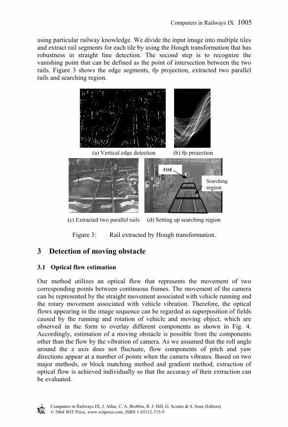
using particular railway knowledge. We divide the input image into multiple tiles and extract rail segments for each tile by using the Hough transformation that has robustness in straight line detection. The second step is to recognize the vanishing point that can be defined as the point of intersection between the two rails. Figure 3 shows the edge segments, θρ projection, extracted two parallel rails and searching region.
Figure 3: Rail extracted by Hough transformation.
3 Detection of moving obstacle
3.1 Optical flow estimation
Our method utilizes an optical flow that represents the movement of two corresponding points between continuous frames. The movement of the camera can be represented by the straight movement associated with vehicle running and the rotary movement associated with vehicle vibration. Therefore, the optical flows appearing in the image sequence can be regarded as superposition of fields caused by the running and rotation of vehicle and moving object, which are observed in the form to overlay different components as shown in Fig. 4. Accordingly, estimation of a moving obstacle is possible from the components other than the flow by the vibration of camera. As we assumed that the roll angle around the z axis does not fluctuate, flow components of pitch and yaw directions appear at a number of points when the camera vibrates. Based on two major methods, or block matching method and gradient method, extraction of optical flow is achieved individually so that the accuracy of their extraction can be evaluated.
Searching
FOE
(a) Vertical edge detection (b) θρ projection
(c) Extracted two parallel rails (d) Setting up searching region
Computers in Railways IX, J. Allan, C. A. Brebbia, R. J. Hill, G. Sciutto & S. Sone (Editors)© 2004 WIT Press, www.witpress.com, ISBN 1-85312-715-9
Computers in Railways IX 1005
region
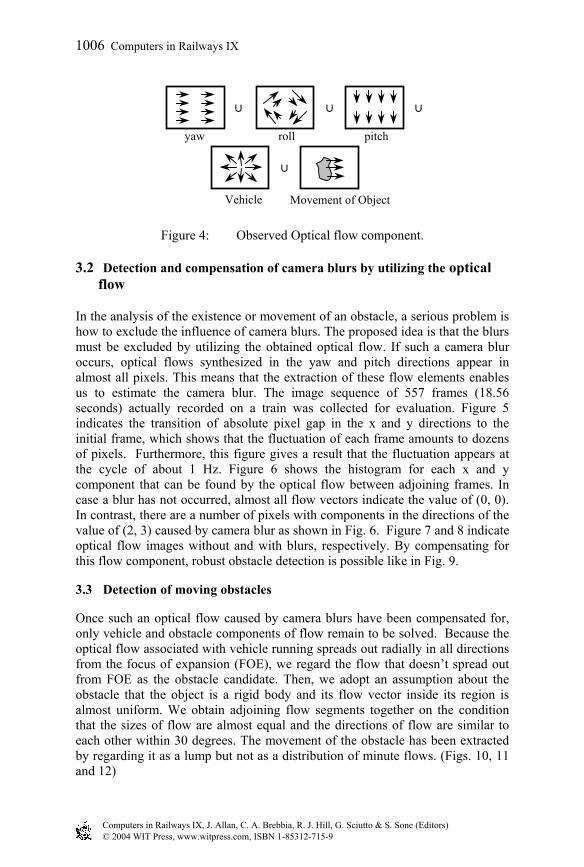
Figure 4: Observed Optical flow component.
3.2 Detection and compensation of camera blurs by utilizing the optical flow
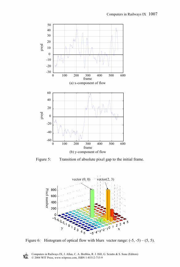
In the analysis of the existence or movement of an obstacle, a serious problem is how to exclude the influence of camera blurs. The proposed idea is that the blurs must be excluded by utilizing the obtained optical flow. If such a camera blur occurs, optical flows synthesized in the yaw and pitch directions appear in almost all pixels. This means that the extraction of these flow elements enables us to estimate the camera blur. The image sequence of 557 frames (18.56 seconds) actually recorded on a train was collected for evaluation. Figure 5 indicates the transition of absolute pixel gap in the x and y directions to the initial frame, which shows that the fluctuation of each frame amounts to dozens of pixels. Furthermore, this figure gives a result that the fluctuation appears at the cycle of about 1 Hz. Figure 6 shows the histogram for each x and y component that can be found by the optical flow between adjoining frames. In case a blur has not occurred, almost all flow vectors indicate the value of (0, 0). In contrast, there are a number of pixels with components in the directions of the value of (2, 3) caused by camera blur as shown in Fig. 6. Figure 7 and 8 indicate optical flow images without and with blurs, respectively. By compensating for this flow component, robust obstacle detection is possible like in Fig. 9.
3.3 Detection of moving obstacles
Once such an optical flow caused by camera blurs have been compensated for, only vehicle and obstacle components of flow remain to be solved. Because the optical flow associated with vehicle running spreads out radially in all directions from the focus of expansion (FOE), we regard the flow that doesn’t spread out from FOE as the obstacle candidate. Then, we adopt an assumption about the obstacle that the object is a rigid body and its flow vector inside its region is almost uniform. We obtain adjoining flow segments together on the condition that the sizes of flow are almost equal and the directions of flow are similar to each other within 30 degrees. The movement of the obstacle has been extracted by regarding it as a lump but not as a distribution of minute flows. (Figs. 10, 11 and 12)
yaw roll pitch
Vehicle i
Movement of Object
∪ ∪ ∪
∪
Computers in Railways IX, J. Allan, C. A. Brebbia, R. J. Hill, G. Sciutto & S. Sone (Editors)© 2004 WIT Press, www.witpress.com, ISBN 1-85312-715-9
1006 Computers in Railways IX
0 100 200 300 400 500 600-60
-40
-20 0
20
40 60
frame (b) y-component of flow
0 100 200 300 400 500 600-30 -20 -10
0 10 20 30 40 50
frame (a) x-component of flow
Figure 5: Transition of absolute pixel gap to the initial frame.
pixel pixel
Pixel number
xy
vector (0, 0) vector(2, 3)
Figure 6: Histogram of optical flow with blurs vector range: (-5, -5) – (5, 5).
Computers in Railways IX, J. Allan, C. A. Brebbia, R. J. Hill, G. Sciutto & S. Sone (Editors)© 2004 WIT Press, www.witpress.com, ISBN 1-85312-715-9
Computers in Railways IX 1007
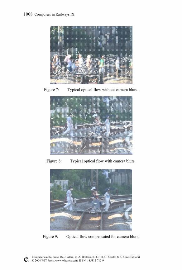
Figure 8: Typical optical flow with camera blurs.
Figure 7: Typical optical flow without camera blurs.
Figure 9: Optical flow compensated for camera blurs.
Computers in Railways IX, J. Allan, C. A. Brebbia, R. J. Hill, G. Sciutto & S. Sone (Editors)© 2004 WIT Press, www.witpress.com, ISBN 1-85312-715-9
1008 Computers in Railways IX
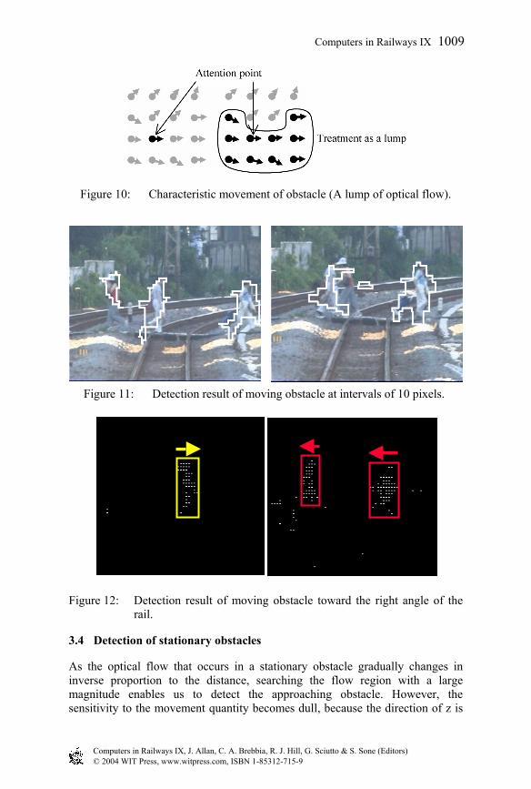
Figure 10: Characteristic movement of obstacle (A lump of optical flow).
Figure 12: Detection result of moving obstacle toward the right angle of the rail.
3.4 Detection of stationary obstacles
As the optical flow that occurs in a stationary obstacle gradually changes in inverse proportion to the distance, searching the flow region with a large magnitude enables us to detect the approaching obstacle. However, the sensitivity to the movement quantity becomes dull, because the direction of z is
Figure 11: Detection result of moving obstacle at intervals of 10 pixels.
Computers in Railways IX, J. Allan, C. A. Brebbia, R. J. Hill, G. Sciutto & S. Sone (Editors)© 2004 WIT Press, www.witpress.com, ISBN 1-85312-715-9
Computers in Railways IX 1009
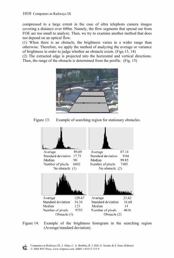
compressed to a large extent in the case of ultra telephoto camera images covering a distance over 600m. Namely, the flow segments that spread out from FOE are too small to analyze. Then, we try to examine another method that does not depend on an optical flow. (1) When there is an obstacle, the brightness varies in a wider range than otherwise. Therefore, we apply the method of analyzing the average or variance of brightness in order to judge whether an obstacle exists. (Figs.13, 14) (2) The extracted edge is projected into the horizontal and vertical directions. Then, the range of the obstacle is determined from the profile. (Fig. 15)
Figure 13: Example of searching region for stationary obstacles.
Figure 14: Example of the brightness histogram in the searching region
(Average/standard deviation).
Computers in Railways IX, J. Allan, C. A. Brebbia, R. J. Hill, G. Sciutto & S. Sone (Editors)© 2004 WIT Press, www.witpress.com, ISBN 1-85312-715-9
1010 Computers in Railways IX

In order to precisely examine the obstacle, we manage to minutely set up the search area that corresponds to curved rails, because the resolution is worse when the distance becomes longer. We determine obstacle exists or not first by the method (1). It shows a tendency that the average and also the standard deviation of brightness become larger when there is an obstacle. In case the average and the standard deviation of the brightness exceed the threshold, therefore, we identify the obstacle position by the procedure in Table 1.
Figure 15: Detection result of stationary obstacle.
Table 1: General flow of stationary obstacle detection.
4 Conclusion
In order to compensate for camera blurs quantitative analysis was performed to estimate the feasibility of optical flow. Two detection algorithms for moving and stationary obstacles are proposed. The former algorithm is based on the analysis of optical flow which characteristically occurs in those obstacles as a lump. In the latter, we focused on the obstacle edge and the brightness contrast difference from the background. We successfully performed experiments under a variety of
Computers in Railways IX, J. Allan, C. A. Brebbia, R. J. Hill, G. Sciutto & S. Sone (Editors)© 2004 WIT Press, www.witpress.com, ISBN 1-85312-715-9
Computers in Railways IX 1011

rail images. As a result, a 600m distant obstacle could be detected with ultra telephoto camera images.
Furthermore, in order to cope with all weather conditions, an experiment using a night view image taken by a low luminance CCD camera or infrared camera was performed to prove the possibility of image processing.
References
[1] Mikio Takaki, Handbook of Image Analysis, Tokyo University Shuppankai, 1995.11.
Computers in Railways IX, J. Allan, C. A. Brebbia, R. J. Hill, G. Sciutto & S. Sone (Editors)© 2004 WIT Press, www.witpress.com, ISBN 1-85312-715-9
1012 Computers in Railways IX