oca guideline for seismic restraint of operational and ... · 2014 - version 1 ottawa chapter oca...
TRANSCRIPT

Supported by the following organizationsOttawa Construction Association
Walls & Ceiling Contractors Association of Ottawa
Mechanical Contractors Association of Ottawa
Consulting Engineers of Ontario - Ottawa Chapter
Electrical Contractors Association of Ottawa
MECHANICAL CONTRACTORSASSOCIATION OF OTTAWA
2014 - VERSION 1
OTTAWA CHAPTER
OCA Guideline for Seismic Restraint of Operational and Functional Components (OFCs) 2014
SEISMIC GUIDE FOR CONSTRUCTION IN OTTAWA REGION

PREFACEThe Guideline for Seismic Restraint of Operational and Functional Components is the result of the dedicated efforts of many
people who volunteered numerous hours to help standardize the seismic designs and construction of operational and functionalcomponents within buildings in the Ottawa Region. The primary authors are 8 members of the OCA Seismic Design Guide Task
Group responsible for reviewing seismic requirements. These members are Seismic engineers and technicians responsible forinspecting and certifying seismic designs and installations. The remaining members of the Seismic Design Guide Task Group
are members of the local Mechanical Contractors Association (MCA), Electrical Contractors Association (ECA), local Ottawa chap-ter of the Consulting Engineers of Ontario, Ottawa Construction Association (OCA), Ottawa Regional Society of Architects (ORSA),and Walls and Ceilings Contractors Association (WACCA).
The Task Group provided direction and guidance to complete this guideline over the past 2 years and produced an invaluabledocument which is intended to help bring some clarity and ultimately standardization within the construction industry whendealing with seismic designs and installations with the Ottawa region.
The hope is to have this document or one similar, adopted and incorporated into the Ontario Building Code, however at thistime it remains only as an unofficial reference guide for those responsible for the design and certification for the seismic restraintof operational and functional components within buildings.
The chairman would like to personally thank the authors for their diligence, expertise, and persistence as well as all the mem-bers of the Task Group. Without these people this document would not have been possible.
Ross McIntyre, P.Eng. PrincipalGoodkey, Weedmark & Associates Ltd. Consulting EngineersChair of OCA Seismic Design Guide Task Group
Authors
Richard Lévesque, ing., P. Eng., LEED AP HTS Engineering Ltd.Jason Kitchen, P. Eng., LEED AP HTS Engineering Ltd.Tom Stevens, P. Eng. Halsall Associated Ltd.Michele Low, M.Eng., P. Eng., ing. TecousticsStacey Perron, Ph. D, P. Eng. Brownstone EngineeringBrent Weatherdon, P. Eng. Cleland Jardine Engineering Ltd.Brea Williams, Ph. D, P. Eng.Ron Giessmann, P. Eng. Vibro-Acoustics
Seismic Design Guide Task Group – Chair Ross McIntyre, P. Eng.
(formed under the auspices of the OCA Standard Practices Committee)
Brea Williams, Ph. D, P. Eng., Mark Jones, P. Eng., Walmar Mechanical Sales, Dwight Brown of PCL Constructors, Albert Celli, P. Eng., of Halsall Associates, Cathy Godin of SK Sheetmetal, James Chapman, HDR Architecture, Michael Cleland, P. Eng., ofCleland Jardine, Ron Giessmann, P. Eng. Vibro-Acoustics, John Graf, P. Eng. of JL Richards Ltd, Domenico Filoso, P. Eng. ofMarcantonio Constructors Inc., Jason Kitchen, P. Eng., LEED AP HTS Engineering Ltd., Richard Lévesque, ing., P. Eng., LEED AP HTS Engineering Ltd., Michele Low, P. Eng., ing. Tecoustics, Ross McIntyre, P. Eng., of Goodkey Weedmark, Stacie Perron, P. Eng. Brownstone Engineering, Bill Pieterson of Doran Contractors, Tony Sottile, P. Eng., of Modern Niagara Group, TomStevens, P. Eng. Halsall Associated Ltd., Hugh Trudeau of Erskine Dredge & Associates, Brent Weatherdon, P. Eng. Cleland Jardine Engineering Ltd.
Disclaimer
The responsibility of determining any seismic requirements to be incorporated into the project will remain the owners/archi-tects sole responsibility. After seismic design analysis, these project requirements will be clearly noted on the drawings andspecifications.
Design Discretion: This document is as a guide to design only. It is the responsibility of the designer to confirmcompliance with all applicable codes, standards, by-laws and regulations
Design Scope: The Seismic Engineer provides a design for anchorage of the equipment to base building structure.The ability of the unit itself, any supporting frames, or the base building to resist the seismic loads is outside thescope of the Seismic Engineer.
Variation from Design: Where the specified design hardware, anchorage layout, or design is not followed, the Seismic Engineer should be contacted to review the proposed modified installation. Any modifications installed without review are at the Contractor’s risk and may require further modifications and/or re-work to meet seismic requirements.
Future modifications: Final sign-off for the seismic restraint design and installation are applicable to the installedcondition only. Any modifications made after sign-off is issued are done at the risk of the owner and should bereviewed by a Seismic Engineer to ensure continued compliance.

Table of Contents
1. Introduction to Building Code Requirements . . . . . . . . . . . . . . . . . . . . . . . . . . . . . . . . . . . . . . . . . . . . . . . . . . . . . . 11.1 Force Calculations – OBC 4.1.8.17(1) . . . . . . . . . . . . . . . . . . . . . . . . . . . . . . . . . . . . . . . . . . . . . . . . . . . . . . . . . . 11.2 Connections to Structure – OBC 4.1.8.17(8) . . . . . . . . . . . . . . . . . . . . . . . . . . . . . . . . . . . . . . . . . . . . . . . . . . . . 21.3 Forces in Hanger Rods – OBC 4.1.8.17(12) . . . . . . . . . . . . . . . . . . . . . . . . . . . . . . . . . . . . . . . . . . . . . . . . . . . . . 21.4 CSA S832-06, Seismic Risk Reduction of Operational and Functional Components (OFCs) of Buildings . . 21.5 Other Publications . . . . . . . . . . . . . . . . . . . . . . . . . . . . . . . . . . . . . . . . . . . . . . . . . . . . . . . . . . . . . . . . . . . . . . . . 2
2. Frequently Asked Questions . . . . . . . . . . . . . . . . . . . . . . . . . . . . . . . . . . . . . . . . . . . . . . . . . . . . . . . . . . . . . . . . . . . 3
3. Seismic Restraint of Architectural Elements: Ceilings , Partition Walls & Wall Mounted Items . . . . . . . . . . . . . 53.1 Ceiling Grids . . . . . . . . . . . . . . . . . . . . . . . . . . . . . . . . . . . . . . . . . . . . . . . . . . . . . . . . . . . . . . . . . . . . . . . . . . . . . 53.2 Drywall Ceilings . . . . . . . . . . . . . . . . . . . . . . . . . . . . . . . . . . . . . . . . . . . . . . . . . . . . . . . . . . . . . . . . . . . . . . . . . . 73.3 Partition Walls . . . . . . . . . . . . . . . . . . . . . . . . . . . . . . . . . . . . . . . . . . . . . . . . . . . . . . . . . . . . . . . . . . . . . . . . . . . . 83.4 Wall Mounted Items . . . . . . . . . . . . . . . . . . . . . . . . . . . . . . . . . . . . . . . . . . . . . . . . . . . . . . . . . . . . . . . . . . . . . . . 9
4. Seismic Restraint of Masonry Blockwalls . . . . . . . . . . . . . . . . . . . . . . . . . . . . . . . . . . . . . . . . . . . . . . . . . . . . . . . . 10
5. Seismic Restraint of Mechanical Equipment . . . . . . . . . . . . . . . . . . . . . . . . . . . . . . . . . . . . . . . . . . . . . . . . . . . . . 105.1 Suspended Pipe . . . . . . . . . . . . . . . . . . . . . . . . . . . . . . . . . . . . . . . . . . . . . . . . . . . . . . . . . . . . . . . . . . . . . . . . . 105.2 Suspended Ductwork . . . . . . . . . . . . . . . . . . . . . . . . . . . . . . . . . . . . . . . . . . . . . . . . . . . . . . . . . . . . . . . . . . . . . 105.3 Rod Stiffeners . . . . . . . . . . . . . . . . . . . . . . . . . . . . . . . . . . . . . . . . . . . . . . . . . . . . . . . . . . . . . . . . . . . . . . . . . . . 115.4 Base Mounted Equipment . . . . . . . . . . . . . . . . . . . . . . . . . . . . . . . . . . . . . . . . . . . . . . . . . . . . . . . . . . . . . . . . . 115.5 Suspended Equipment . . . . . . . . . . . . . . . . . . . . . . . . . . . . . . . . . . . . . . . . . . . . . . . . . . . . . . . . . . . . . . . . . . . . 115.6 Wall Mounted Equipment . . . . . . . . . . . . . . . . . . . . . . . . . . . . . . . . . . . . . . . . . . . . . . . . . . . . . . . . . . . . . . . . . 115.7 Roof Mounted Equipment, Ductwork and Piping . . . . . . . . . . . . . . . . . . . . . . . . . . . . . . . . . . . . . . . . . . . . . . 125.8 General Notes . . . . . . . . . . . . . . . . . . . . . . . . . . . . . . . . . . . . . . . . . . . . . . . . . . . . . . . . . . . . . . . . . . . . . . . . . . . 12
6. Seismic Restraint of Fire Protection Systems . . . . . . . . . . . . . . . . . . . . . . . . . . . . . . . . . . . . . . . . . . . . . . . . . . . . 136.1 Sway Bracing Requirements . . . . . . . . . . . . . . . . . . . . . . . . . . . . . . . . . . . . . . . . . . . . . . . . . . . . . . . . . . . . . . . 136.2 Restraint Requirements . . . . . . . . . . . . . . . . . . . . . . . . . . . . . . . . . . . . . . . . . . . . . . . . . . . . . . . . . . . . . . . . . . . 136.3 Restraint Straps . . . . . . . . . . . . . . . . . . . . . . . . . . . . . . . . . . . . . . . . . . . . . . . . . . . . . . . . . . . . . . . . . . . . . . . . . 136.4 Sway Brace Designs . . . . . . . . . . . . . . . . . . . . . . . . . . . . . . . . . . . . . . . . . . . . . . . . . . . . . . . . . . . . . . . . . . . . . . 13
7. Seismic Restraint of Electrical Equipment . . . . . . . . . . . . . . . . . . . . . . . . . . . . . . . . . . . . . . . . . . . . . . . . . . . . . . . 147.1 Suspended Electrical Systems . . . . . . . . . . . . . . . . . . . . . . . . . . . . . . . . . . . . . . . . . . . . . . . . . . . . . . . . . . . . . 147.2 Rod Stiffeners . . . . . . . . . . . . . . . . . . . . . . . . . . . . . . . . . . . . . . . . . . . . . . . . . . . . . . . . . . . . . . . . . . . . . . . . . . . 147.3 Base Mounted Equipment . . . . . . . . . . . . . . . . . . . . . . . . . . . . . . . . . . . . . . . . . . . . . . . . . . . . . . . . . . . . . . . . . 147.4 Suspended Equipment . . . . . . . . . . . . . . . . . . . . . . . . . . . . . . . . . . . . . . . . . . . . . . . . . . . . . . . . . . . . . . . . . . . . 147.5 Wall Mounted Equipment . . . . . . . . . . . . . . . . . . . . . . . . . . . . . . . . . . . . . . . . . . . . . . . . . . . . . . . . . . . . . . . . . 157.6 Roof Mounted Equipment . . . . . . . . . . . . . . . . . . . . . . . . . . . . . . . . . . . . . . . . . . . . . . . . . . . . . . . . . . . . . . . . . 157.7 General Notes . . . . . . . . . . . . . . . . . . . . . . . . . . . . . . . . . . . . . . . . . . . . . . . . . . . . . . . . . . . . . . . . . . . . . . . . . . . 15
References . . . . . . . . . . . . . . . . . . . . . . . . . . . . . . . . . . . . . . . . . . . . . . . . . . . . . . . . . . . . . . . . . . . . . . . . . . . . . . . . . . . 16

Definitions
ASCE: American Society of Civil Engineers
ASHRAE: American Society of Heating and Refrigerating and Air-Conditioning Engineers
Base Building Engineer: The structural engineer responsible for design of the base building.
CISCA: Ceilings and Interior Systems Construction Association
Contractor: The company responsible for the installation and restraint of a non-structural component for their specific scope of work. Typical scope includes sheet metal,plumbing, electrical and architectural.
Hazardous materials: Chemical gases, chemical liquids, fossil fuels and their products of combustion.
NFPA: National Fire Protection Association
Non-structural components: Elements of a building that are not part of the structural system, including mechanical and electrical systems and architectural components, as defined in section 4.1.8.17 of the Ontario Building Code. Also referred to as Operational and Functional Components (OFCs).
OBC: Ontario Building Code (2006)
OFCs: Operational and Functional Components as defined in CAN/CSA-S832-06 (R2011)Seismic Risk Reduction of Operational and Functional Components (OFCs) of Buildings
Power-actuated fastener: Nail or stud driven with great force into a hard surface with the help of a powdercharge or cartridge.
SMACNA: Sheet Metal and Air Conditioning Contractors’ National Association
Seismic Engineer: A licensed professional engineer with expertise in seismic design, who is retainedby a Contractor or Seismic Supplier for the seismic restraint design of non-structural components. Seismic Engineer must have a Certificate of Authorizationin the adequate Province, with a minimum of $1 million Professional Liability Insurance.
Seismic Supplier: A supplier who provides restraint hardware and restraint engineering to the Contractor.
Seismic rated Restraint hardware rated by independent testing authorities for use in seismic restraint hardware: events. Acceptable manufacturers are those listed with membership in VISCMA.
VISCMA: The Vibration Isolation and Seismic Control Manufacturers Association. Membersinclude Kinetics Noise Control, Mason Industries Inc., M.W. Saussé & Co. Inc., Thybar Corporation, The VMC Group, Vibration Eliminator Company, Vibro-Acoustics, CalDyn/California Dynamics, and Tolco.
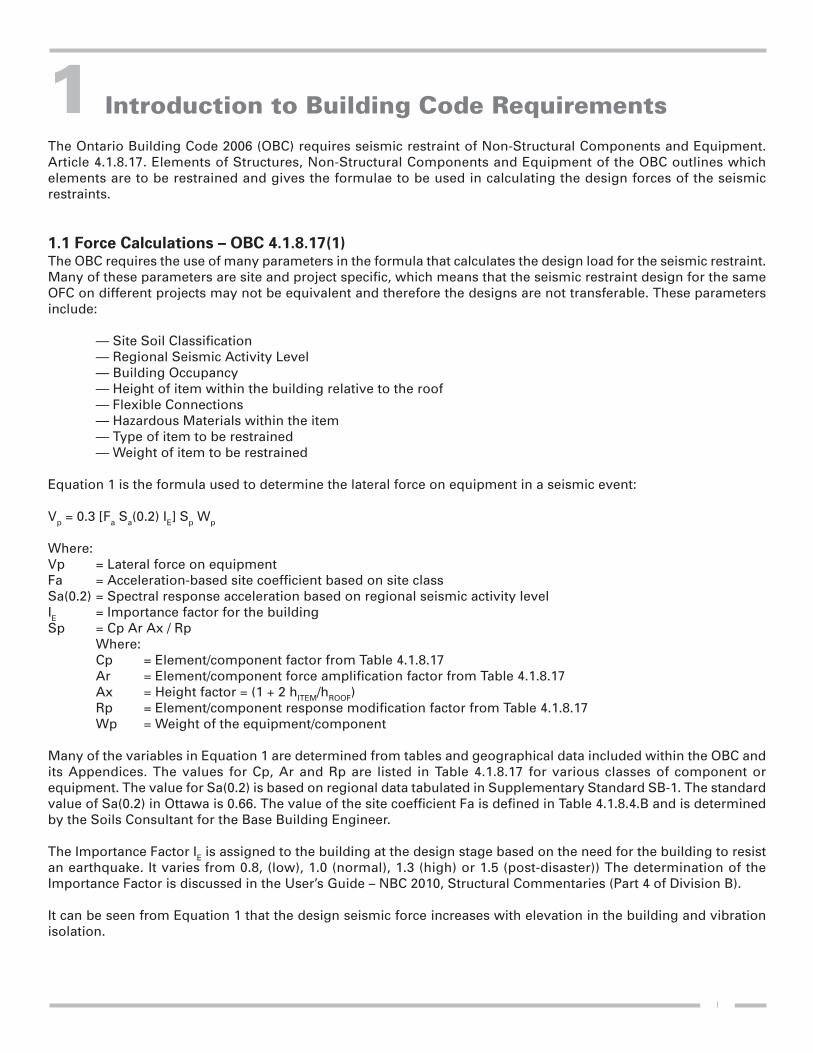
Introduction to Building Code Requirements
The Ontario Building Code 2006 (OBC) requires seismic restraint of Non-Structural Components and Equipment.Article 4.1.8.17. Elements of Structures, Non-Structural Components and Equipment of the OBC outlines whichelements are to be restrained and gives the formulae to be used in calculating the design forces of the seismicrestraints.
1.1 Force Calculations – OBC 4.1.8.17(1)The OBC requires the use of many parameters in the formula that calculates the design load for the seismic restraint.Many of these parameters are site and project specific, which means that the seismic restraint design for the sameOFC on different projects may not be equivalent and therefore the designs are not transferable. These parametersinclude:
— Site Soil Classification— Regional Seismic Activity Level— Building Occupancy— Height of item within the building relative to the roof— Flexible Connections— Hazardous Materials within the item— Type of item to be restrained— Weight of item to be restrained
Equation 1 is the formula used to determine the lateral force on equipment in a seismic event:
Vp = 0.3 [Fa Sa(0.2) IE] Sp Wp
Where:Vp = Lateral force on equipmentFa = Acceleration-based site coefficient based on site classSa(0.2) = Spectral response acceleration based on regional seismic activity levelIE = Importance factor for the buildingSp = Cp Ar Ax / Rp
Where:Cp = Element/component factor from Table 4.1.8.17Ar = Element/component force amplification factor from Table 4.1.8.17Ax = Height factor = (1 + 2 hITEM/hROOF)Rp = Element/component response modification factor from Table 4.1.8.17Wp = Weight of the equipment/component
Many of the variables in Equation 1 are determined from tables and geographical data included within the OBC andits Appendices. The values for Cp, Ar and Rp are listed in Table 4.1.8.17 for various classes of component orequipment. The value for Sa(0.2) is based on regional data tabulated in Supplementary Standard SB-1. The standardvalue of Sa(0.2) in Ottawa is 0.66. The value of the site coefficient Fa is defined in Table 4.1.8.4.B and is determinedby the Soils Consultant for the Base Building Engineer.
The Importance Factor IE is assigned to the building at the design stage based on the need for the building to resistan earthquake. It varies from 0.8, (low), 1.0 (normal), 1.3 (high) or 1.5 (post-disaster)) The determination of theImportance Factor is discussed in the User’s Guide – NBC 2010, Structural Commentaries (Part 4 of Division B).
It can be seen from Equation 1 that the design seismic force increases with elevation in the building and vibrationisolation.
1
1

The code provides for certain buildings to be exempt from the requirements of article 4.1.8.17. This exemptionapplies to non post-disaster buildings that have a product of IE Fa Sa(0.2) less than 0.35. In the Ottawa region, thevalue of Sa(0.2) = 0.66, and with a Site class A (best possible site classification) the value of Fa would be 0.764. Thisexemption will never apply in the Ottawa region because the product of Ie Fa Sa(0.2) is 0.50.
1.2 Connections to StructureNon-structural component attachments shall be bolted, welded or otherwise positively fastened to structure. Frictiondue to gravity loads is not permitted to restrain non-structural components. Post-installed anchors into concreteshall be prequalified for seismic applications (i.e with seismic load ratings and approvals) and as specified by theseismic engineer.
1.3 Forces in Hanger Rods – OBC 4.1.8.17(12)The seismic restraints for suspended equipment, pipes, ducts and electrical cable trays, are not permitted to subjectthe hanger rods to bending.
Designers and installers cannot rely on the 12” rule. For that rule to apply, non-moment generating connection and12” of free movement around the equipment would have to be provided. In most cases these conditions are eitherimpractical or almost impossible to achieve.
1.4 CSA S832-06, Seismic Risk Reduction of Operational and Functional Components (OFCs)
of BuildingsThis standard was developed to address the concerns of OFCs as relating to occupant safety, building operationsand damage to property during a seismic event. This standard is meant to be used in conjunction with buildingcodes and trade guidelines for engineers, building officials and facility managers among others to assess, mitigateand protect OFCs from causing unnecessary bodily harm and building damage during an earthquake. It outlinesmethods of evaluation and analysis, risk reduction and assessment procedures as well as, selecting and sizing ofOFC seismic restraints.
1.5 Other PublicationsThe design force requirements and methods of analysis given in the OBC and CSA S832-06 (R2011) are then usedin conjunction with the guidelines set out by the individual trade or professional association that deal with the typeof OFC being restrained. For example, the American Society of Heating, Refrigerating and Air-Conditioning Engineers(ASHRAE) has published ‘A Practical Guide to Seismic Restraints’ to establish standard seismic restraint details onpiping, ductwork and mechanical equipment. The Sheet Metal and Air Conditioning Contractors’ National Association(SMACNA), National Fire Protection Association (NFPA) and Ceilings and Interior Systems Construction Association(CISCA) are among some of the other trades to have introduced seismic restraint guidelines in their publications.These publications typically address which items will and will not require restraints and establish typical restraintdetails for their respective trades.
Finally, the ASCE 7-10 document “Minimum Design Loads for Buildings and Other Structures” provides valuableguidance in terms of potential exemptions from requirements of seismic restraints. Since this is an American code,geographic/site data from Canada must be converted to American factors to determine where each exemption mightapply. At the time of this writing, no conversion factor or procedure has been established to relate the Americanfactors to Canadian conditions and requirements.
2

Frequently Asked Questions
What is the process for obtaining seismic restraint sign off in Ottawa?
The typical process to obtain a seismic restraint sign off in the City of Ottawa begins with the Contractor hiring aSeismic Supplier for their individual scope of work. The Seismic Supplier will review the Contractor’s scope of work,including installed equipment and systems, and provide a seismic restraint design to the Contractor. Prior to initiationof the design, the Base Building Engineer must provide the Site Soil Classification, and the building importancelevel.
The Seismic Supplier will provide to the Contractor a set of seismic restraint shop drawings with a P.Eng. seal in theProvince of Ontario. These shop drawings should clearly identify the equipment/systems reviewed and theequipment/systems requiring restraint. These shop drawings must clearly show all forces transferred to the structure.
The Seismic Supplier typically provides the Contractor with all of the required seismically rated hardware, or designfor the application of standard hardware to implement the restraint system.
The Seismic Supplier and/or the Seismic Engineer shall review the installation of the restraint systems and uponapproval of said installation shall provide a letter sealed by a Professional Engineer for the contracted scope of work.
What are some of the basic code items that need to be known?
— The seismic forces transferred to the structure at restraint points must be reviewed by the BaseBuilding Engineer.
— Hardware used for seismic restraint must be seismically rated by an independent testing facilitylab.
— Power actuated fasteners and drop-in anchors shall not be used for tension loads due to theseismic restraint of a non-structural element.
— Housekeeping pads must be attached to the structure and reinforced• Where pads are not attached to structure, anchors must penetrate through the housekeeping
pad and attach to the structural slab below.
• This is not typically included in the scope of the Seismic Supplier/Engineer, unless specificallyidentified in the contractor’s section of the project specifications.
— Friction due to gravity may not be used as a restraint. Mechanical attachment is required.
— Anchorage of exterior mounted equipment should be reviewed for both seismic and wind loads.However, design for wind loading is not typically included in the scope of the Seismic Engineer,unless specifically identified in the contractor’s section of the project specifications.• In many cases, wind loading will create forces exceeding those created by a seismic event.
What are some of the common practice items related to installation that need to be known?
— All restraints for a system (e.g., pipe/conduit run, duct run, equipment) must attach to only onestructural element. Avoid bracing an element to separate portions of the structure that may actdifferently in response to an earthquake.• For example, do not connect a transverse brace to a wall and a longitudinal brace to the roof at
the same brace location..
— Pipe/conduit and duct gravity supports (i.e., hanger rods) cannot be used as restraint for thatequipment.
3
2

— Rod stiffeners do not act as restraints.• Rod stiffeners may be required on hanger rods at restraint locations, but rod stiffeners alone
do not act as restraints.
— Cable/rigid restraints installed zero degrees to the horizontal eliminates the need to provide rodstiffeners as no vertical force is generated.
— All restraints fastened to structural steel joists must be anchored to the top chord of the joist,within 4 inches of a panel point.
— Cable/rigid restraints may not be attached to steel joists/beams with standard beam clamps.
— Roof mounted items that require seismic restraint must be mechanically anchored to the basebuilding. • Anchorage to stone pavers and roof materials is not acceptable (i.e. elements glued to roof
system).
— Seismic gas valves are usually not acceptable as a replacement to seismic restraint applied to gaspiping. • Gas valves may only be used as an additional safety measure in a seismic event.
4

Seismic Restraint of Architectural Elements: Ceilings, Partition Walls & Wall Mounted Items
3.1 Ceiling GridsSuspended ceilings that are designed to support ceiling panels/tiles, and possibly lighting fixtures, ceiling mountedair terminals, or other ceiling mounted services must satisfy the requirements outlined below.
Ceilings with area 144 square feet or less, surrounded by walls that connect directly to the structure above, may beexempt from the requirement for seismic restraint.
Ceilings with area 2500 square feet or more require a seismic separation joint or full height partition that breaks theceiling up into areas not exceeding 2500 square feet. Each 2500 square foot area requires perimeter angles (Table3.1) and horizontal restraints.
Table 3.1 summarizes the requirements for lateral supports, perimeter angles, compression posts, and openings inthe ceiling.
5
3
Table 3.1: Requirements for seismic restraint of ceiling grid [CISCA (2004)]
COMPONENT REQUIREMENT
Lateral restraints
Size and spacing
Attachment
Perimeter conditions
Compression posts
Sprinkler openings
– Provide four No. 12 gauge wires secured to the main runner within 2 inches of thecross runner intersection and splayed 90 degrees from each other at an angle notexceeding 45 degrees from the plane of the ceiling (refer to Figure 3.1)
– Space restraints at 12 foot c/c in each direction– Locate first set of restraints within 6 feet of grid perimeter– Provide minimum 6 inches of clearance between restraints and any unrestrained
duct/pipe in the ceiling space– Restraint location to be marked on plan by Seismic Engineer
– Wires must be connected to structure above– Anchorage to structure above must be rated for at least 200lb
– Tie ends of main runners and cross runners together to prevent spreading– Width of the perimeter supporting closure angle shall not be less than 2.0 inches. – Main/cross runners shall be attached to the closure angle along two adjacent walls.
Runners along remaining two edges must not be attached to walls. (refer to Figure 3.2)– A minimum clearance of 0.75 inches must be provided between wall and runners
along all edges (refer to Figure 3.2)
– Provide a compression post at each restraint location (refer to Figure 3.1)– Strut to be fastened to the ceiling grid and the structure above– Strut size to be provided by Seismic Engineer
– Sprinkler heads and other penetrations through the ceiling shall have a 2 inch oversizering, sleeve or adapter through the ceiling tile to allow for free movement of at least 1 inch in all horizontal directions.
– Alternatively, a swing joint that can accommodate 1 inch of ceiling movement in allhorizontal directions is permitted at the top of the sprinkler head extension.
– This requirement does not apply where rigid braces are used to brace the ceiling grid.

Figure 3.1: Lateral restraint of ceiling grid
Figure 3.2: Recommended detail at ceiling grid edge (CISCA, 2004)
6

Light fixtures within the ceiling grid also require supplementary support, as detailed in Table 3.2.
Mechanical services within the ceiling grid also require supplementary support, as detailed in Table 3.3.
3.2 Drywall CeilingsDrywall ceilings are subject to the same seismic restraint requirements as those outlined for ceiling grids. However, exemptions are possible in two situations:
— Flat ceilings constructed of drywall that screw attached to suspension members, and extend inone level from wall to wall, or
— Free floating suspended ceilings that:• Are smaller than 1,000 square feet, and• Have lateral clearance around the ceiling such that the system will not come into contact with
another building element through pendulum action.
7
Table 3.2: Restraint of light fixtures within ceiling grid [CISCA (2004)]
COMPONENT REQUIREMENT
All light fixtures– Fixture must be attached to ceiling grid– Fasteners must have capacity to transfer 100% of fixture
weight to grid in all directions
– Provide one No. 12 gauge wire from fixture housing tostructure above
– Wire may be slack
– Provide two No. 12 gauge wire from at opposite corners offixture, from fixture housing to structure above
– Wires may be slack
– Support fixture independently from structure above
– Provide one No. 9 gauge wire from fixture housing to structureabove without using ceiling grid for direct support
Supplementary support
Fixtures weighing less than 10lb
Fixtures weighing10lb or more, andless than 56lb
Fixtures weighing56lb or more
Pendant hung lightfixtures
Table 3.3: Restraint of mechanical services within ceiling grid [CISCA (2004)]
COMPONENT REQUIREMENT
– Provide positive attachment from fixture to ceiling grid
– Provide positive attachment from fixture to ceiling grid– Provide two No. 12 gauge wires at opposite corners of fixture,
from fixture housing to structure above– Wires may be slack
– Support fixture independently from structure above
Supplementary support
Fixtures weighing lessthan 20lb
Fixtures weighing 20lb ormore, and less than 56lb
Fixtures weighing 56lb or more

Achieving exemption for flat ceilings means that wire restraints and compression posts are not required. However,control joints must be provided in the drywall to minimize cracking in the ceiling. A typical control joint is shown inFigure 3.3. The frequency of control joints depends on whether perimeter relief (clearance between the ceiling edgeand the wall) is provided, and is shown in Table 3.4. At a control joint, a 12.5mm continuous opening should beprovided between gypsum boards for insertion of a surface –mounted joint, and ceiling framing should be interruptedwherever there is a control joint in the structure.
Figure 3.3: Recommended detail at drywall ceiling control joint (USG, 2010)
3.3 Partition WallsThe Seismic Engineer should review the design of the partition wall and its connection to the base structure, andprovide restraint details specific to each project. However, there are some common approaches used to properlyrestrain metal stud partition walls, which are highlighted in Figure 3.4.
These details include:
— A continuous bottom track that is fastened to both the studs, and the slab below;
— A primary continuous top track that is fastened to the slab above;
— A secondary continuous top track that is fastened to the studs, and
— A gap to allow for deflection of the slab above.
Where partition walls are not full-height, they require diagonal bracing from the top of the wall up to the undersideof structure. Details of the size and spacing of the braces, and anchorage to structure will be provided by the SeismicEngineer.
8
Table 3.4: Location of control joints in drywall ceiling (USG, 2010)
COMPONENT MAX SINGLE DIMENSION MAX SINGLE AREA
Ceiling interior
With perimeter relief 50 feet 2500 sq. ft.
Without perimeter relief 30 feet 900 sq. ft.
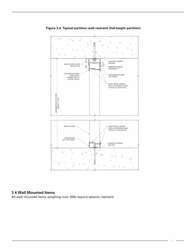
Figure 3.4: Typical partition wall restraint (full-height partition)
3.4 Wall Mounted ItemsAll wall mounted items weighing over 20lb require seismic restraint.
9

Seismic Restraint of Masonry Block walls
Seismic restraint details for load bearing and non-load bearing masonry walls are included in the scope of the BaseBuilding Structural Engineer.
Seismic Restraint of Mechanical Equipment
5.1 Suspended PipeSuspended pipe includes, but is not limited to, cast-iron, steel, copper, stainless steel, and PVC piping.
The following pipe must be restrained:
— 1” diameter pipe and larger, containing hazardous materials (gas, diesel, etc…) and medicalpiping (oxygen, etc…) [ASCE/SEI 7-10]
— 1” diameter pipe and larger, for pipe that is required to function for life safety after an earthquake[ASCE/SEI 7-10]
— 2.5” diameter pipe and larger, in general areas [ASHRAE RP-812 and SMACNA]
— 1.25” diameter pipe and larger, in mechanical rooms [ASHRAE RP-812]
— Trapeze assemblies supporting pipes with a total weight (including contents) greater than 10lb/ft (ASCE 7-10)
Pipe that is less than the sizes shown above may be exempt from restraint, as long as high deformability piping isused and provisions are made to avoid impact with other building components.
In certain instances, pipe smaller than noted above might require restraint. These instances apply for pipe that isrequired for continued operation of a facility, and its failure could impair continued operation of the facility.
The maximum seismic restraint spacing for different kind of pipes is as follow:
— 20’-0” for lateral and 40’-0” for longitudinal for applicable No-Hub (e.g. cast-iron pipe) and PVC orPVDF [ASHRAE RP-82]
— 20’-0” for lateral and 40’-0” for longitudinal for piping containing hazardous materials [SMACNA]
— 40’-0” for lateral and 80’-0” for longitudinal for applicable steel and copper pipe with weldedlongitudinal, brazed grooved, or screwed connections [ASHRAE RP-82]
For piping located on the roof, please refer to section 5.7.
5.2 Suspended DuctworkThe following ductwork must be restrained:
— All duct required to function for life safety after an earthquake [ASCE/SEI 7-10]
— Square/rectangular duct with face area 6 square feet or greater [ASHRAE RP-812]
— Round duct 28” diameter and larger [ASHRAE RP-812]
— Trapeze assemblies supporting multiple ducts with a total weight greater than 10lb/ft (ASCE 7-10)
Ductwork that is less than the sizes shown above may be exempted from restraint as long as provisions are madeto avoid impact with other building components.
10
4
5

Duct containing hazardous materials, should be reviewed by the Seismic Engineer.
In certain instances, ductwork smaller than noted above might require restraint. These instances apply for ductworkthat is required for continued operation of a facility, and its failure could impair continued operation of the facility.
The maximum seismic restraint spacing for ductwork is 30’-0” for lateral restraint and 60’-0” for longitudinal restraint[ASHRAE RP-812].
For ductwork located on the roof, please refer to section 5.7.
5.3 Rod StiffenersRod stiffeners are required where the hanger rod exceeds the maximum length as shown in the seismic restraintcalculations sheets. Stiffeners are only required at restraint locations.
5.4 Base Mounted EquipmentBase mounted equipment requires restraint if any of the following conditions apply:
— Required to function for life safety after an earthquake; or
— Required for continued operation of a facility, and its failure could impair continued operation ofthe facility; or
— Connected to, or contains hazardous materials, or
— Subject to overturning under seismic loads; or
— Weighs 400lb or greater; or
— Mounted on a stand that is 4 feet or more from the floor.
The above conditions are as per point 13.1.4 of the ASCE/SEI 7-10.
5.5 Suspended EquipmentSuspended equipment requires restraint if any of the following conditions apply:
— Required to function for life safety after an earthquake, or
— Required for continued operation of a facility, and its failure could impair continued operation ofthe facility, or
— Contains hazardous materials; or
— Rigidly attached to duct and weighs 75lb and greater; or [ASCE/SEI 7-10]
— Hung independently or with flexible connections to pipe or duct and weighs 20lb and greater[ASCE/SEI 07-10].
Any unbraced piping or ductwork attached to the inline component must have adequate flexibility to accommodatedifferential displacement.
5.6 Wall Mounted EquipmentWall mounted equipment requires restraint if any of the following conditions are satisfied:
— Required to function for life safety after an earthquake, or
— Required for continued operation of a facility, and its failure could impair continued operation ofthe facility, or
— Contains hazardous materials, or
— Weighs 20lb and greater [ASCE/SEI 07-10].
11

5.7 Roof Mounted Equipment, Ductwork and Piping
Roof mounted equipment must be installed on a structural frame, a seismically-rated roof curb, or a structuralcurb/frame. The curb or frame must be mechanically anchored to the base building. Items shall not be mounted onsleepers or pads that are not mechanically anchored to the structure (also refer to section 5.4).
5.8 General Notes
Some additional requirements for trapezed systems include:
— Any trapeze with a combined system weight that meets or exceeds 10lb/ft [ASHRAE RP-812].
— All pipes must be mechanically clamped to the trapeze at all restraint locations.
— Trapezed systems must have one set of longitudinal restraints attached to each side of thetrapeze.
When installing restraints, the following requirements must be satisfied:
— Where the pipe or duct size reduces below the required dimensions noted above, the finalrestraint shall be installed at that transition location in the pipe/duct run.
— All restraints on a pipe/duct run must attach to only one of the following: wall, floor or slab above.
— All longitudinal restraints must be connected directly to the pipe and not to the outside of theinsulation. For heating/cooling plumbing lines, offset is required to permit the installation oflateral restraints on the hanger or the exterior insulation that will act as longitudinal restraints.These offsets should be located at 80’-0” spacing maximum or less. The figure 5.1 belowillustrates that arrangement.
— All longitudinal restraints must be located within 4” of a hanger rod. This hanger rod may requirestiffening as per the Seismic Engineer’s design.
When restraints are attached to structural steel, the following requirements apply:
— All restraints must be attached to the top chord of joists, within 4” of a panel point.
— Standard beam clamps cannot be used to attach restraints to steel joists/beams.
Where suspended pipe/duct penetrates a wall or floor, the following requirements apply:
— Walls and floors may be used as transverse restraints for suspended pipe/duct as long as there isa tight fit, and the pipe/duct is at a 90-degree angle to the wall/floor.
— Where perimeter angles are used to attach the pipe/duct to the wall/floor, then it may be used as atransverse and longitudinal restraint.
— Metal stud partition walls may not be used as restraints.
Where mechanical equipment is mounted in ceiling grids, refer to Section 3 for restraint requirements.
Table 5.1: Location of seismic restraints for heating/cooling lines
12

Seismic Restraint of Fire Protection Systems
The National Fire Protection Association (NFPA 2007) includes in its publications seismic restraint requirements insection 9.3.5, Sway Bracing. Sway bracing is equivalent to seismic restraints as described in previous sections. Theyare installed on the pipe to restrict the lateral and vertical motion of the pipe during an earthquake. Lateral swaybracing stops the motion of the pipe perpendicular to the length of pipe while longitudinal braces inhibit movementalong the main axis of the pipe. NFPA also refers to “restraint”, which applies to branch line piping 2 inches indiameter and smaller.
6.1 Sway Bracing RequirementsTable 6.1 outlines the sway bracing requirements as per the NFPA.
The exceptions to sway braces are as follows:
— Braces are not required if the pipe is individually supported with rod less than 6 inches in length,from top of pipe to attachment point at structure.
— Braces are not required if the pipe is installed tight to structure with U-type hooks.
6.2 Restraint RequirementsBranch line piping that is 2 inches or less diameter is considered capable of considerable movement without damage.A degree of support less than that of “sway bracing” is required, as addressed in Section 9.3.6 of NFPA. “Restraint”for this size of pipe can be one of the following:
— A listed sway brace assembly;
— A wraparound u-hook, or
— No. 12 wire installed at least 45 degrees from the vertical plane and anchored on both sides of the pipe.
6.3 Restraint StrapsIn addition to the sway brace locations, all hangers using a C-type clamp to attach to structure must include arestraining strap. This strap is sized in accordance with the diameter of pipe being supported and shall wrap aroundthe beam flange a minimum of 1 inch.
6.4 Sway Brace DesignsThe seismic engineer will select the components of the sway brace to satisfy the loading requirements of the NFPA.If appropriate, the seismic engineer may also allow floor penetrations and wall penetrations (block or concrete) toact as four-way braces and lateral braces, respectively.
13
6
Table 6.1: Sway Brace Requirements
MAXIMUM MAXIMUM END COMMENTS
SPACING DISTANCE
Lateral Sway
Brace
Longitudinal
Sway Brace
Risers,
4-way Brace
40 feet 6 feet
80 feet 20 feet
25 feet 3 feet
– Brace all feeds and cross mains regardless of size
– Brace all branch lines with a diameter ≥ 2.5 inches
– Last length of pipe on a feed or cross main to be laterallyrestrained
– A lateral brace may serve as a longitudinal brace, and viceversa, if it is located less than 24 inches from thecenterline of the pipe being braced

Seismic Restraint of Electrical Equipment
7.1 Suspended Electrical SystemsThe following conduit sizes must be restrained:
— All conduit that is required to function for life safety after an earthquake
— All conduit that is required for continued operation of a facility, and its failure could impaircontinued operation of the facility
— 2.5” diameter conduit and larger [ASCE/SEI 07-10]
— Trapezes assemblies supporting conduits, and bus ducts or cable tray with contents weightgreater than 10 lb/ft [ASCE/SEI 07-10]
Conduit that is less than the sizes shown above may be exempt from restraint, as long as provisions are made toavoid impact with other building components.
7.2 Rod StiffenersRod stiffeners are required where the hanger rod exceeds the maximum length as shown in the seismic restraintcalculations sheets. Stiffeners are only required at restraint locations.
7.3 Base Mounted EquipmentBase mounted equipment requires restraint if any of the following conditions apply:
— Required to function for life safety after an earthquake; or
— Required for continued operation of a facility, and its failure could impair continued operation ofthe facility; or
— Connected to, or contains hazardous materials, or
— Subject to overturning under seismic loads; or
— Weighs 400lb or greater; or
— Mounted on a stand that is 4 feet or more from the floor [ASCE/SEI 07-10].
7.4 Suspended EquipmentSuspended equipment requires restraint if any of the following conditions apply:
— Required to function for life safety after an earthquake, or
— Required for continued operation of a facility, and its failure could impair continued operation ofthe facility, or
— Contains hazardous materials; or
— Rigidly attached to pipe or duct and weighs 75lb and greater; or
— Hung independently or with flexible connections to pipe or duct and weighs 20lb and greater[ASCE/SEI 07-10].
Any unbraced conduit attached to the inline component must have adequate flexibility to accommodate differentialdisplacement.
14
7

7.5 Wall Mounted EquipmentWall mounted equipment requires restraint if any of the following conditions apply:
— Required to function for life safety after an earthquake, or
— Required for continued operation of a facility, and its failure could impair continued operation ofthe facility, or
— Contains hazardous materials, or
— Weighs 20lb and greater [ASCE/SEI 07-10].
7.6 Roof Mounted EquipmentRoof mounted equipment must be installed on a structural frame, a seismically-rated roof curb, or a structuralcurb/frame. The curb or frame must be mechanically anchored to the base building. Items shall not be mounted onsleepers or pads that are not mechanically anchored to the structure.
7.7 General NotesSome additional requirements for trapezed systems include:
— Any trapeze with a combined system weight that meets or exceeds 10lb/ft.
— All conduits must be mechanically clamped to the trapeze at all restraint locations.
— Trapezed systems must have one set of longitudinal restraints attached to each side of thetrapeze.
When installing restraints, the following requirements must be satisfied:
— Where the conduit size reduces below the required dimensions noted above, the final restraintshall be installed at that transition location in the pipe/duct run.
— All restraints on a conduit or cable-tray run must attach to only one of the following: wall, floor orslab above.
— All longitudinal restraints must be located within 4” of a hanger rod. This hanger rod may requirestiffening as per the Seismic Engineer’s design.
When restraints are attached to structural steel, the following requirements apply:
— All restraints must be attached to the top chord of joists, within 4” of a panel point.
— Standard beam clamps cannot be used to attach restraints to steel joists/beams.
Where electrical equipment is mounted in ceiling grids, refer to Section 3 for restraint requirements.
15

References
ASHRAE (1999). Practical Guide to Seismic Restraint. American Society of Heating, Refrigerating and Air-Conditioning Engineers, Atlanta, Georgia.
ASCE (2006). Minimum Design Loads for Buildings and Other Structures. American Society of Civil Engineers,Reston, Virginia.
CAN/CSA S832-06 (R2011). Seismic Risk Reduction of Operational and Functional Components (OFCs) of Buildings.Canadian Standards Association, Mississauga, Ontario.
CISCA (2004). Guidelines for Seismic Restraint for Direct Hung Suspended Ceiling Assemblies. Ceilings and InteriorSystems Construction Association, St. Charles, Illinois.
NFPA13 (2007). Standard for the Installation of Sprinkler Systems. National Fire Protection Association.
OBC (2006). Ontario Building Code. Ministry of Municipal Affairs and Housing, Ontario.
SMACNA (2008). Seismic Restraint Manual Guidelines for Mechanical Systems. Sheet Metal and Air-ConditioningContractors’ National Association Inc., Chantilly, Virginia.
16

17

18

19

20