occlusion handling method for ubiquitous augmented reality
TRANSCRIPT
Occlusion Handling Method for Ubiquitous Augmented Reality Using Reality Capture Technology and GLSL
Suyang Dong1, Chen Feng1, and Vineet R. Kamat1 1 Laboratory for Interactive Visualization in Engineering, Department of Civil and Environmental Engineering, University of Michigan, Room 1318, G.G.Brown, 2350 Hayward Street, Ann Arbor, MI 48109; Tel 734-764-4325; Fax 734-764-4292; email: dsuyang, cforrest, [email protected]
ABSTRACT:
The primary challenge in generating convincing Augmented Reality (AR) graphics is to project 3D models onto a user’s view of the real world and create a temporal and spatial sustained illusion that the virtual and real objects co-exist. Regardless of the spatial relationship between the real and virtual objects, traditional AR graphical engines break the illusion of co-existence by displaying the real world merely as a background, and superimposing virtual objects on the foreground. This research proposes a robust depth sensing and frame buffer algorithm for handling occlusion problems in ubiquitous AR applications. A high-accuracy Time-of-flight (TOF) camera is used to capture the depth map of the real-world in real time. The distance information is processed using the OpenGL Shading Language (GLSL) and rendered into the graphics depth buffer, allowing accurate depth resolution and hidden surface removal in composite AR scenes. The designed algorithm is validated in several indoor and outdoor experiments using the SMART AR framework.
INTRODUCTION
As a novel visualization technology, Augmented Reality (AR) has gained widespread attention and seen prototype applications in multiple engineering disciplines for conveying simulation results, visualizing operations design, inspections, etc. For example, by blending real-world elements with virtual reality, AR helps to alleviate the extra burden of creating complex contextual environments for visual simulations (Behzadan, et al., 2009a). As an information supplement to the real environment, AR has also been shown to be capable of appending georeferenced information to a real scene to inspect earthquake-induced building damage (Kamat, et al., 2007), or in the estimation of construction progress (Golparvar-Fard, et al., 2009). In both cases, the composite AR view is composed of two distinct groups of virtual and real objects, and they are merged together by a set of AR graphical algorithms.
Spatial accuracy and graphical credibility are the two keys in the implementation of successful AR graphical algorithms, while the primary focus of this research is exploring a robust occlusion algorithm for enhancing graphical credibility in ubiquitous AR environments. In an ideal scenario, AR graphical algorithms should have the ability to intelligently blend real and virtual objects in all three dimensions, instead of superimposing all virtual objects on top of a real-world background as is the case in most current AR approaches. The result of composing an AR scene without considering the relative depth of the involved real and virtual objects is that the graphical entities in the scene appear to “float” over the real background rather than blending or co-existing with real objects in that scene. The occlusion problem is more complicated in outdoor AR where the user expects to navigate the space freely and the relative depth between involved virtual and real content is changing arbitrarily with
494
Copyright ASCE 2011 Computing in Civil Engineering 2011Downloaded 09 Mar 2012 to 141.212.44.24. Redistribution subject to ASCE license or copyright. Visit http://www.ascelibrary.org
COMPUTING IN CIVIL ENGINEERING
time.
Several researchers have explored the AR occlusion problem from different perspectives: (Wloka, et al., 1995) implemented a fast-speed stereo matching algorithm that infers depth maps from a stereo pair of intensity bitmaps. However random gross errors blink virtual objects on and off and turn out to be very distracting; (Berger, 1997) proposed a contour based approach but with the major limitation that the contours need to be seen from frame to frame; (Lepetit, et al., 2000) refined the previous method by a semi-automated approach that requires the user to outline the occluding objects in the key-views, and then the system automatically detects these occluding objects and handles uncertainties on the computed motion between two key frames. Despite the visual improvements, the semi-automated method is only appropriate for post-processing; (Fortin, et al., 2006) exhibited both model-based using bounding box and depth-based approach using stereo camera. The former one only works with static viewpoint, and the latter is subject to low-textured areas; (Ryu, et al., 2010) tried to increase the accuracy of depth map by region of interest extraction method using background subtraction and stereo depth algorithms, however only simple background examples were demonstrated; (Tian, et al., 2010) also designed an interactive segmentation and object tracking method for real-time occlusion, but their algorithm fails in the situation where virtual objects are in front of real objects.
In this paper, the authors propose a robust AR occlusion algorithm that uses real-time Time-of-flight (TOF) camera, RGB video camera and the OpenGL frame buffer to correctly resolve the depth of real and virtual objects in AR visual simulations. Compared with previous work, this approach enables improvements in three aspects: 1) Ubiquitous: TOF camera capable of suppressing background illumination enables the algorithm and implemented system to work in both indoor and outdoor environments. It puts the least limitation on context and illumination conditions compared with any previous approach; 2) Robust: Due to the depth-buffering employed, this method can work regardless of the spatial relationship among involved virtual and real objects; 3) Fast: The authors take advantage of OpenGL texture and OpenGL Shading Language (GLSL) fragment shader to parallelize the sampling of depth map and rendering into the frame buffer. A recent publication (Koch, et al., 2009) describes a paralleled research effort that adopted a similar approach for TV production in indoor environments with 3D model constructed beforehand.
DEPTH BUFFER COMPARISON APPROACH
In this section, the methodology and computing framework for resolving incorrect occlusion are introduced. This approach takes advantage of OpenGL depth buffering on a two-stage rendering basis.
Distance Data Source
Accurate measurement of the distance from the virtual and real object to the eye is the fundamental step for correct occlusion. In the outdoor AR environment, the distance from the virtual object to the viewpoint is calculated using Vincenty algorithm (Vincenty, 1975) with the geographical locations of the virtual object and the user. Location of the virtual object is decided in the event simulation phase. Meanwhile, location of the user is tracked by Real-time Kinematic (RTK) GPS. The ARMOR platform (Dong, et al., 2010) utilizes Trimble AgGPS 332 along with Trimble AgGPS RTK Base 450/900 to continuously track the user’s position up to centimeter level accuracy.
495
Copyright ASCE 2011 Computing in Civil Engineering 2011Downloaded 09 Mar 2012 to 141.212.44.24. Redistribution subject to ASCE license or copyright. Visit http://www.ascelibrary.org
COMPUTING IN CIVIL ENGINEERING
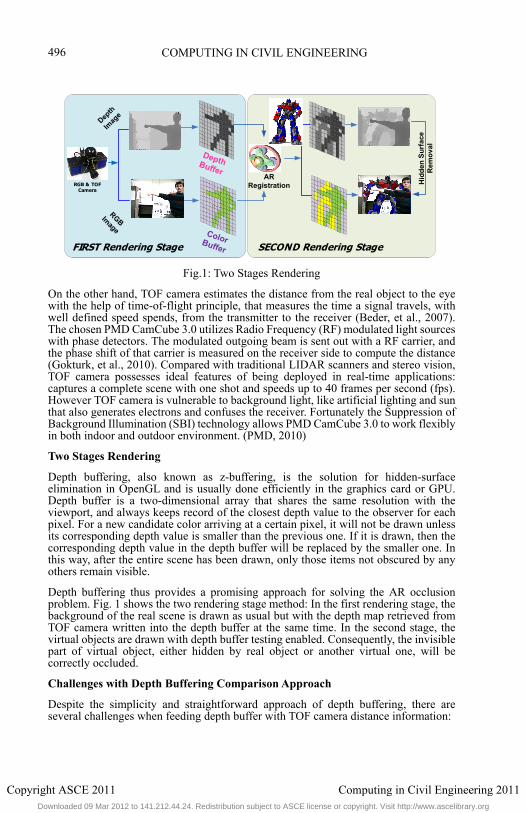
Fig.1: Two Stages Rendering
On the other hand, TOF camera estimates the distance from the real object to the eye with the help of time-of-flight principle, that measures the time a signal travels, with well defined speed spends, from the transmitter to the receiver (Beder, et al., 2007). The chosen PMD CamCube 3.0 utilizes Radio Frequency (RF) modulated light sources with phase detectors. The modulated outgoing beam is sent out with a RF carrier, and the phase shift of that carrier is measured on the receiver side to compute the distance (Gokturk, et al., 2010). Compared with traditional LIDAR scanners and stereo vision, TOF camera possesses ideal features of being deployed in real-time applications: captures a complete scene with one shot and speeds up to 40 frames per second (fps). However TOF camera is vulnerable to background light, like artificial lighting and sun that also generates electrons and confuses the receiver. Fortunately the Suppression of Background Illumination (SBI) technology allows PMD CamCube 3.0 to work flexibly in both indoor and outdoor environment. (PMD, 2010)
Two Stages Rendering
Depth buffering, also known as z-buffering, is the solution for hidden-surface elimination in OpenGL and is usually done efficiently in the graphics card or GPU. Depth buffer is a two-dimensional array that shares the same resolution with the viewport, and always keeps record of the closest depth value to the observer for each pixel. For a new candidate color arriving at a certain pixel, it will not be drawn unless its corresponding depth value is smaller than the previous one. If it is drawn, then the corresponding depth value in the depth buffer will be replaced by the smaller one. In this way, after the entire scene has been drawn, only those items not obscured by any others remain visible.
Depth buffering thus provides a promising approach for solving the AR occlusion problem. Fig. 1 shows the two rendering stage method: In the first rendering stage, the background of the real scene is drawn as usual but with the depth map retrieved from TOF camera written into the depth buffer at the same time. In the second stage, the virtual objects are drawn with depth buffer testing enabled. Consequently, the invisible part of virtual object, either hidden by real object or another virtual one, will be correctly occluded.
Challenges with Depth Buffering Comparison Approach
Despite the simplicity and straightforward approach of depth buffering, there are several challenges when feeding depth buffer with TOF camera distance information:
FIRST Rendering Stage SECOND Rendering Stage
Depth Buffer
Color Buffer
Depth
Imag
e
RGBImage
ARRegistration H
idd
en S
urf
ace
Re
mo
val
RGB & TOFCamera
496
Copyright ASCE 2011 Computing in Civil Engineering 2011Downloaded 09 Mar 2012 to 141.212.44.24. Redistribution subject to ASCE license or copyright. Visit http://www.ascelibrary.org
COMPUTING IN CIVIL ENGINEERING
1) After being processed through the OpenGL graphics pipeline and written into the depth buffer, the distance between the OpenGL camera and the virtual object is not the physical distance at all (Shreiner, et al., 2006). The transformation model is explained in section 3.1. Therefore the distance for each pixel from the real object to the viewpoint given by the TOF camera has to be processed by the same transformation model, before it is written into the depth buffer for comparison.
2) Traditional glDrawPixels() command can be extremely slow when writing a two-dimensional array, i.e. the depth map, into the frame buffer. Section 4 introduces an alternative and efficient approach using OpenGL texture and GLSL.
3) The resolution of TOF depth map is fixed as 200*200 while that of the depth buffer can be arbitrary, depending on the resolution of the viewport. This implies the necessity of interpolation between the TOF depth map and the depth buffer. Section 4 also takes advantage of OpenGL texture to fulfill interpolation task.
4) There are three cameras for rendering an AR space: Video camera captures RGB values of the real scene as the background, and its result is written into the color buffer; TOF camera acquires the depth map of the real scene, and its result is written into the depth buffer; OpenGL camera projects virtual objects on top of real scene with its result written into both color and depth buffer. To ensure correct registration and occlusion, all of them have to share the same projection parameters: aspect ratio and focal length. While the projection parameters of OpenGL camera are adjustable, the intrinsic parameters of video camera and TOF camera do not agree: i.e. different principle points, focal lengths and distortion models. Therefore an image registration method is designed to find the correspondence between the depth and RGB image.
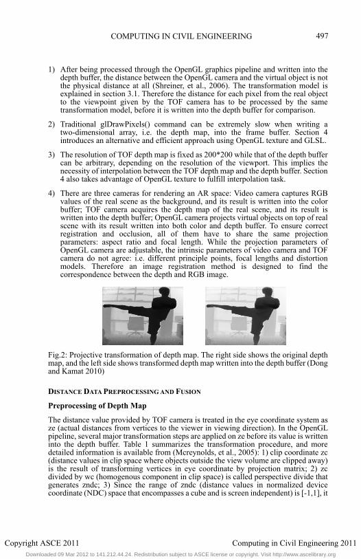
Fig.2: Projective transformation of depth map. The right side shows the original depth map, and the left side shows transformed depth map written into the depth buffer (Dong and Kamat 2010)
DISTANCE DATA PREPROCESSING AND FUSION
Preprocessing of Depth Map
The distance value provided by TOF camera is treated in the eye coordinate system as ze (actual distances from vertices to the viewer in viewing direction). In the OpenGL pipeline, several major transformation steps are applied on ze before its value is written into the depth buffer. Table 1 summarizes the transformation procedure, and more detailed information is available from (Mcreynolds, et al., 2005): 1) clip coordinate zc (distance values in clip space where objects outside the view volume are clipped away) is the result of transforming vertices in eye coordinate by projection matrix; 2) zc divided by wc (homogenous component in clip space) is called perspective divide that generates zndc; 3) Since the range of zndc (distance values in normalized device coordinate (NDC) space that encompasses a cube and is screen independent) is [-1,1], it
497
Copyright ASCE 2011 Computing in Civil Engineering 2011Downloaded 09 Mar 2012 to 141.212.44.24. Redistribution subject to ASCE license or copyright. Visit http://www.ascelibrary.org
COMPUTING IN CIVIL ENGINEERING
needs to be offset and scaled by the depth buffer range [0,1] before it is sent to the depth buffer.
Table 1: The transformation steps applied on the raw TOF depth image.
Name Meaning Operation Expression Range
Ze Distance to the
viewpoint
Acquired by TOF camera (0,
+∞)
Zc Clip coordinate after
projection
transformation
Mortho * Mperspective * [Xe Ye Ze We]T
2
n and f is the near and far plane, We is the homogenous component in eye coordinate, and usually equal to 1
[-n,f]
Zndc Normalized device
coordinate
Zc / Wc (Wc = Ze, and is the
homogenous component in
clip coordinate
2 [-1,1]
Zd Value sent to depth
buffer
(Zndc+1) / 2 2 0.5 [0,1]
Depth Map and RGB Image Fusion
Because of the different intrinsic parameters, i.e. principle points, focal lengths, and distortion models, of the RGB and TOF cameras, image registration is indispensible before any of them can be written into frame buffers. Given the intrinsic matrixes of both cameras, and relative extrinsic matrixes between these two cameras, one solution of mapping from an image point x to another image point x’ is formulized as follows, (Hartley, et al., 2003)
′ ′ ′ / K and K’ are the intrinsic matrixes of the RGB and TOF camera respectively. R and T represent the relative rotation and translation from image TOF to image RGB. Z is depth of point xTOF in the physical world, i.e. distance to the TOF camera. This model implies the way of registering the depth map with the RGB image, since Z is known for each pixel in the TOF depth map. K and K’ are known with camera calibration, while R and T come from the decomposition of essential matrix between two cameras. The essential matrix is the specialization of the fundamental matrix to the case of normalized image coordinates. E = K’TFK (Hartley, et al., 2003). E represents essential matrix, and F represents fundamental matrix, that is known by matching identical points on two images.
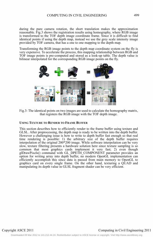
Successful implementation of the above model depends on two conditions: the first one is accurate camera calibration, that is responsible for extracting relative extrinsic parameters, as well as registration itself. The second one is the accurate extrinsic parameters. As Fig.3 shows, in order to cover the same physical space as much as possible, the RGB camera is located right on top of TOF camera, that makes short baseline situation inevitable. Short baseline indicates slight error in camera calibration and finding identical points can be amplified in the registration process. The low resolution of TOF image (200*200) makes it hard to calibrate TOF camera and select identical points with little errors.
Thus we adopt an alternative approach by taking advantages of the short baseline itself, and replacing the image registration problem with a homography model. Even though theoretically homography only works for matching points on two physical planes or
498
Copyright ASCE 2011 Computing in Civil Engineering 2011Downloaded 09 Mar 2012 to 141.212.44.24. Redistribution subject to ASCE license or copyright. Visit http://www.ascelibrary.org
COMPUTING IN CIVIL ENGINEERING
during the pure camera rotation, the short translation makes the approximation reasonable. Fig.3 shows the registration results using homography, where RGB image is transformed to the TOF depth image coordinate frame. Since it is difficult to find identical points if using the depth map, instead we use the grey scale intensity image provided by TOF camera, that has a one to one mapping to the depth map.
Transforming the RGB image points to the depth map coordinate system on the fly is very expensive. To accelerate the process, this mapping relationship between RGB and TOF image points is pre-computed and stored as a look-up table. The depth value is bilinear interpolated for the corresponding RGB image points on the fly.
Fig.3: The identical points on two images are used to calculate the homography matrix, that registers the RGB image with the TOF depth image.
USING TEXTURE TO RENDER TO FRAME BUFFER
This section describes how to efficiently render to the frame buffer using texture and GLSL. After preprocessing, the depth map is ready to be written into the depth buffer. However a challenging issue is how to write to depth buffer fast enough so that real time rendering is possible: 1) the arbitrary size of the depth buffer requires interpolation of the original 200*200 image. While software interpolation can be very slow, texture filtering presents a hardware solution here since texture sampling is so common that most graphics cards implement it very fast; 2) even though glDrawPixels() command with GL_DPETH_COMPONENT parameter provides an option for writing array into depth buffer, no modern OpenGL implementation can efficiently accomplish this since data is passed from main memory to OpenGL to graphics card on every single frame. On the other hand, texturing a QUAD and manipulating its depth value in GLSL fragment shader can be very efficient.
TOF Camera
499
Copyright ASCE 2011 Computing in Civil Engineering 2011Downloaded 09 Mar 2012 to 141.212.44.24. Redistribution subject to ASCE license or copyright. Visit http://www.ascelibrary.org
COMPUTING IN CIVIL ENGINEERING
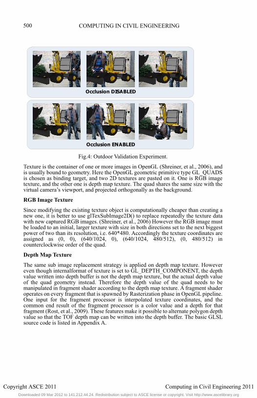
Fig.4: Outdoor Validation Experiment.
Texture is the container of one or more images in OpenGL (Shreiner, et al., 2006), and is usually bound to geometry. Here the OpenGL geometric primitive type GL_QUADS is chosen as binding target, and two 2D textures are pasted on it. One is RGB image texture, and the other one is depth map texture. The quad shares the same size with the virtual camera’s viewport, and projected orthogonally as the background.
RGB Image Texture
Since modifying the existing texture object is computationally cheaper than creating a new one, it is better to use glTexSubImage2D() to replace repeatedly the texture data with new captured RGB images. (Shreiner, et al., 2006) However the RGB image must be loaded to an initial, larger texture with size in both directions set to the next biggest power of two than its resolution, i.e. 640*480. Accordingly the texture coordinates are assigned as (0, 0), (640/1024, 0), (640/1024, 480/512), (0, 480/512) in counterclockwise order of the quad.
Depth Map Texture
The same sub image replacement strategy is applied on depth map texture. However even though internalformat of texture is set to GL_DEPTH_COMPONENT, the depth value written into depth buffer is not the depth map texture, but the actual depth value of the quad geometry instead. Therefore the depth value of the quad needs to be manipulated in fragment shader according to the depth map texture. A fragment shader operates on every fragment that is spawned by Rasterization phase in OpenGL pipeline. One input for the fragment processor is interpolated texture coordinates, and the common end result of the fragment processor is a color value and a depth for that fragment (Rost, et al., 2009). These features make it possible to alternate polygon depth value so that the TOF depth map can be written into the depth buffer. The basic GLSL source code is listed in Appendix A.
Occlusion DISABLED
Occlusion ENABLED
500
Copyright ASCE 2011 Computing in Civil Engineering 2011Downloaded 09 Mar 2012 to 141.212.44.24. Redistribution subject to ASCE license or copyright. Visit http://www.ascelibrary.org
COMPUTING IN CIVIL ENGINEERING
VALIDATION
Despite the outstanding performance of TOF camera in speed and accuracy, the biggest technical challenge of it is the modular error, since the receiver decides the distance by measuring the phase offset of the carrier. Ranges are mod the maximum range, that is decided by the RF carrier wavelength. For instance, the standard measurement range of CamCube3.0 is 7m. (PMD, 2010) If an object happens to be 8m away from the camera, its distance is represented as 1m (8 mod 7) on the depth map instead of 8m. This can bring incorrect occlusion in outdoor condition, where ranges can easily go beyond 7m. The authors have been looking into object detection, segmentation etc. to mitigate the limitation. For now, the experiment range is intentionally restricted to within 7m.
The TOF camera is positioned approximately 7m facing the wall of a building, so that ambiguous distance is ruled out. A small excavator model (accredited to J-m@n from Google 3D Warehouse community) is positioned about 5m away from the TOF camera, and the author is standing in front of the excavator. Scenarios for both occlusion function enabled and disabled are shown. It is obvious that occlusion provides much better spatial cues and realism for outdoor AR visual simulation.
CONCLUSION AND FUTURE WORK
This paper described research that designed and implemented an innovative approach to resolve AR occlusion in ubiquitous environments using real-time TOF camera distance data and the OpenGL frame buffer. Sets of experimental results demonstrated promising depth visual cues and realism in AR visual simulations. However, several challenging issues remain outstanding and are currently being investigated by the authors. For example, the fusion algorithm using homography to register RGB image with the depth map is subject to ghost effects in some cases, whose causes are not clearly identified yet. Ghost effect implies over-occluding virtual objects and leaving blank gaps between virtual and real objects. Secondly, the authors acknowledge that the current 7m average operational range of TOF camera puts a limitation on fully outdoor simulation visualization. However the occlusion algorithm designed here is generic and scalable so that future hardware with improved range and accuracy can be plugged into the current AR visualization system with little modification to the core algorithm. Meanwhile, the authors are studying the feasibility of implementing hybrid methods, like stereo vision and object detection, to mitigate this limitation.
REFERENCE
Acharya, T., & Ray, A. K. (2005). Image processing : principles and applications, John Wiley & Sons, Inc.
Beder, C., Bartczak, B., & Koch, R. (2007). A Comparison of PMD-Cameras and Stereo-Vision for the Task of Surface Reconstruction using Patchlets, Computer Vision and Pattern Recognition, Minneapolis, MN, 1-8. .
Behzadan, A. H., & Kamat, V. R. (2009a). Scalable Algorithm for Resolving Incorrect Occlusion in Dynamic Augmented Reality Engineering Environments, Journal of Computer-Aided Civil and Infrastructure Engineering, Vol. 25, No.1, 3-19.
Behzadan, H. A., & Kamat, R. V. (2009b). Automated Generation of Operations Level Construction Animations in Outdoor Augmented Reality, Journal of Computing in Civil Engineering, Vol.23, No.6, 405-417.
Berger, M.-O. (1997). Resolving Occlusion in Augmented Reality: a Contour Based
501
Copyright ASCE 2011 Computing in Civil Engineering 2011Downloaded 09 Mar 2012 to 141.212.44.24. Redistribution subject to ASCE license or copyright. Visit http://www.ascelibrary.org
COMPUTING IN CIVIL ENGINEERING
Approach without 3D Reconstructioin, Proceedings of CVPR (IEEE Conference on Computer Vision and Pattern Recognition, Puerto Rico.
Dong, S., & Kamat, V. R. (2010). Robust Mobile Computing Framework for Visualization of Simulated Processes in Augmented Reality, Proceedings of the 2010 Winter Simulation Conference, Baltimore, USA.
Fortin, P.-A., & Ebert, P. (2006). Handling Occlusions in Real-time Augmented Reality: Dealing with Movable Real and Virtual Objects, Proceedings of the 3rd Canadian Conference on Computer and Robot Vision, Laval University, Quebec, Canada.
Gokturk, B. S., Yalcin, H., & Bamji, C. (2010). A Time-Of-Flight Depth Sensor - System Description, Issues and Solutions, Proceedings of the 2004 Conference on Computer Vision and Pattern Recognition Workshop, Washington, DC, USA, 35-44.
Golparvar-Fard, M., Pena-Mora, F., Arboleda, C. A., & Lee, S. (2009). Visualization of construction progress monitoring with 4D simulation model overlaid on time-lapsed photographs, Journal of Computing in Civil Engineering, Vol. 23, No. 4, 391-404.
Hartley, R., & Zisserman, A. (2003). Multiple View Geometry in Computer Vision(Second Edition).
Kamat, V. R., & El-Tawil, S. (2007). Evaluation of Augmented Reality for Rapid Assessment of Earthquake-Induced Building Damage, Journal of Computing in Civil Engineering, Vol. 21, No. 5, 303-310.
Koch, R., Schiller, I., Bartczak, B., Kellner, F., & Koser, K. (2009). MixIn3D: 3D Mixed Reality with ToF-Camera, Lecture Notes in Computer Science, Vol. 5742, 126-141.
Lepetit, V., & Berger, M.-O. (2000). A Semi-Automatic Method for Resolving Occlusion in Augmented Reality, IEEE Computer Society Conference on Computer Vision and Pattern Recognition, Hilton Head, South Carolina.
Mcreynolds, T., & Blythe, D. (2005). Advanced Graphics Programming Using OpenG, San Francisco, CA: Dlsevier Inc.
OSGART. (2010). Main Page. Retrieved from OSGART: http://www.osgart.org/wiki/Main_Page
PMD. (2010). PMD CamCube 3.0. Retrieved July 2010, from PMD Technologies: http://www.pmdtec.com/fileadmin/pmdtec/downloads/documentation/datenblatt_camcube3.pdf
Rost, R. J., Licea-Kane, B., & ginsberg, d. (2009). OpenGL Shading Language (3rd Edition), Addison-Wesley Professional.
Ryu, S.-W., Han, J.-H., Jeong, J., Lee, S. H., & Park, J. I. (2010). Real-Time Occlusion Culling for Augmented Reality, 16th Korea-Japan Joint Workshop on Frontiers of Computer Vision, Hiroshima Japan, 498-503.
Shreiner, D., Woo, M., Neider, J., & Davis, T. (2006). OpenGL Programming Guide (Fifth Edition).
Tian, Y., Guan, T., & Wang, C. (2010). Real-Time Occlusion Handling in Augmented Reality Based on an Object Tracking Approach, Sensors , 2885-2900.
502
Copyright ASCE 2011 Computing in Civil Engineering 2011Downloaded 09 Mar 2012 to 141.212.44.24. Redistribution subject to ASCE license or copyright. Visit http://www.ascelibrary.org
COMPUTING IN CIVIL ENGINEERING
Vincenty, T. (1975). Direct and inverse solutions of geodesics on the ellipsoid with application of nested equations, In Survey Reviews, Ministry of Overseas Development, 88-93.
Wloka, M. M., & Anderson, B. G. (1995). Resolving Occlusion in Augmented Reality. Symposium on Interactive 3D Graphics Proceedings ACM New York, NY, USA, 5-12.
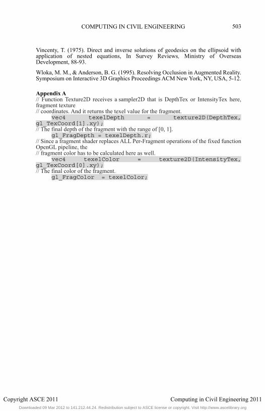
Appendix A // Function Texture2D receives a sampler2D that is DepthTex or IntensityTex here, fragment texture // coordinates. And it returns the texel value for the fragment.
vec4 texelDepth = texture2D(DepthTex, gl_TexCoord[1].xy); // The final depth of the fragment with the range of [0, 1].
gl_FragDepth = texelDepth.r; // Since a fragment shader replaces ALL Per-Fragment operations of the fixed function OpenGL pipeline, the // fragment color has to be calculated here as well.
vec4 texelColor = texture2D(IntensityTex, gl_TexCoord[0].xy); // The final color of the fragment.
gl_FragColor = texelColor;
503
Copyright ASCE 2011 Computing in Civil Engineering 2011Downloaded 09 Mar 2012 to 141.212.44.24. Redistribution subject to ASCE license or copyright. Visit http://www.ascelibrary.org