occoquan multipurpose pedestrian trail bridge … of...occoquan multipurpose pedestrian trail bridge...
TRANSCRIPT
Occoquan Multipurpose Pedestrian Trail Bridge Project Fairfax County, Virginia
B&N Project No. 26032 September 15, 2017
ii
TABLE OF CONTENTS Section Page No.
EXECUTIVE SUMMARY ....................................................................................................................... iii
I. INTRODUCTION.......................................................................................................................... 1
II. SITE DESCRIPTION AND PROPOSED CONSTRUCTION .................................................. 1
III. GEOLOGIC SETTING................................................................................................................. 2
IV. SCOPE OF THE FIELD EXPLORATION ................................................................................ 4
V. SUBSURFACE CONDITIONS .................................................................................................... 5
A. Stratification ............................................................................................................................. 5 B. Groundwater Conditions .......................................................................................................... 6
VI. GEOTECHNICAL RECOMMENDATIONS ............................................................................. 6
A. Foundation ............................................................................................................................... 6 Helical Piers ..................................................................................................................................... 6 Shallow Foundation ......................................................................................................................... 7 B. Abutment Walls ........................................................................................................................ 8 Abutments Backfill .......................................................................................................................... 9 C. Site Classification for Seismic Design ..................................................................................... 9
VII. CONSTRUCTION RECOMMENDATIONS ............................................................................. 9
A. Site Preparation ........................................................................................................................ 9 B. Foundation Construction ........................................................................................................ 10 Foundation Construction – Shallow Foundation ........................................................................... 11 C. Compacted Fill ....................................................................................................................... 12 D. Construction Water Control ................................................................................................... 13
VIII. ADDITIONAL SERVICES RECOMMENDED ....................................................................... 14
IX. LIMITATIONS ............................................................................................................................ 14
APPENDICES
APPENDIX A - FIGURES & TABLES
Figure 1: Site Location Map
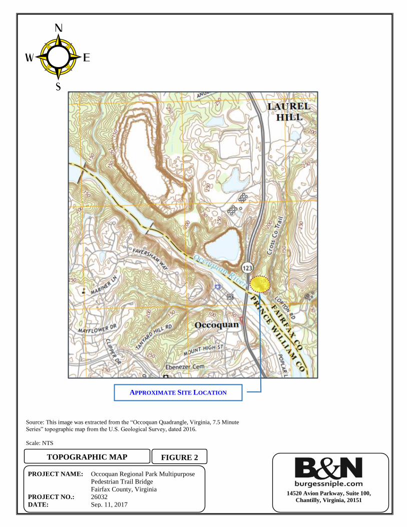
Figure 2: Topographic Map
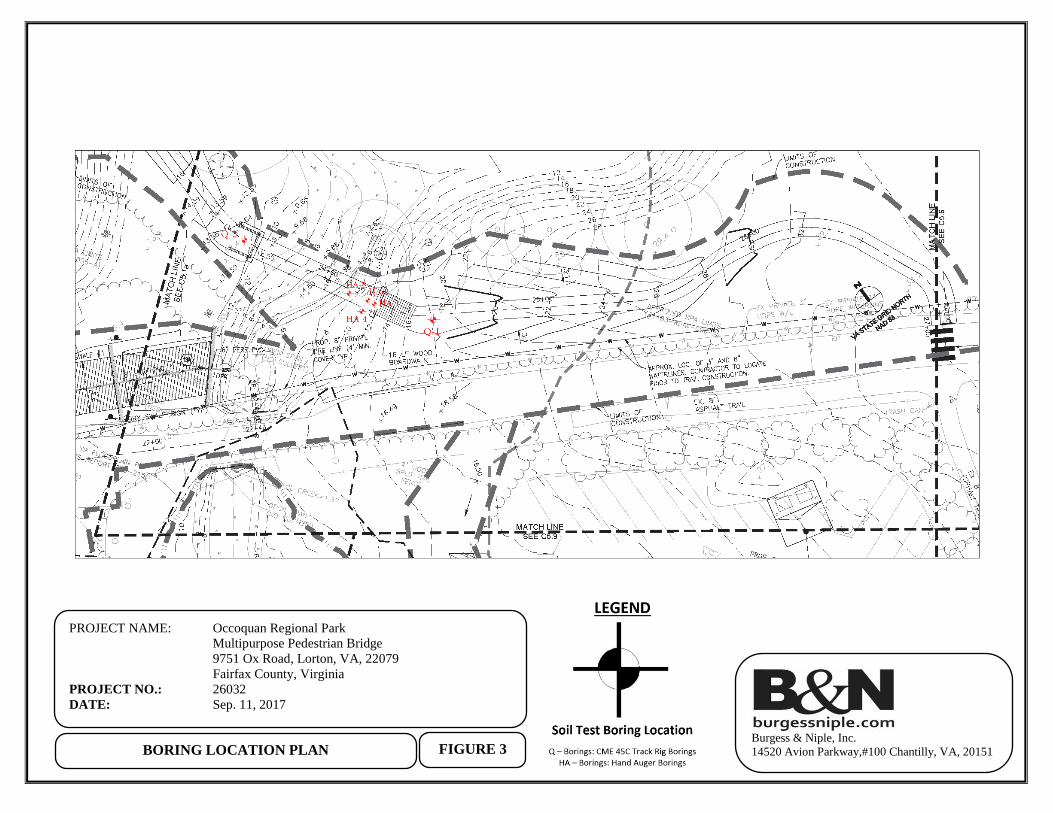
Figure 3: Boring Location Plan
Figure 4: Soil Survey Map
APPENDIX B - FIELD OPERATIONS
Key to Symbols and Classifications
Test Boring Logs (2)
Hand Auger Records (4)
Occoquan Multipurpose Pedestrian Trail Bridge Project Fairfax County, Virginia
B&N Project No. 26032 September 15, 2017
iii
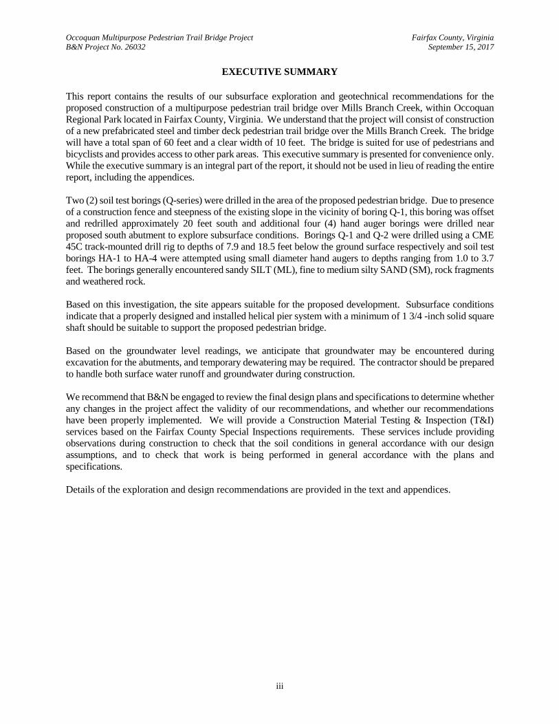
EXECUTIVE SUMMARY
This report contains the results of our subsurface exploration and geotechnical recommendations for the
proposed construction of a multipurpose pedestrian trail bridge over Mills Branch Creek, within Occoquan
Regional Park located in Fairfax County, Virginia. We understand that the project will consist of construction
of a new prefabricated steel and timber deck pedestrian trail bridge over the Mills Branch Creek. The bridge
will have a total span of 60 feet and a clear width of 10 feet. The bridge is suited for use of pedestrians and
bicyclists and provides access to other park areas. This executive summary is presented for convenience only.
While the executive summary is an integral part of the report, it should not be used in lieu of reading the entire
report, including the appendices.
Two (2) soil test borings (Q-series) were drilled in the area of the proposed pedestrian bridge. Due to presence
of a construction fence and steepness of the existing slope in the vicinity of boring Q-1, this boring was offset
and redrilled approximately 20 feet south and additional four (4) hand auger borings were drilled near
proposed south abutment to explore subsurface conditions. Borings Q-1 and Q-2 were drilled using a CME
45C track-mounted drill rig to depths of 7.9 and 18.5 feet below the ground surface respectively and soil test
borings HA-1 to HA-4 were attempted using small diameter hand augers to depths ranging from 1.0 to 3.7
feet. The borings generally encountered sandy SILT (ML), fine to medium silty SAND (SM), rock fragments
and weathered rock.
Based on this investigation, the site appears suitable for the proposed development. Subsurface conditions
indicate that a properly designed and installed helical pier system with a minimum of 1 3/4 -inch solid square
shaft should be suitable to support the proposed pedestrian bridge.
Based on the groundwater level readings, we anticipate that groundwater may be encountered during
excavation for the abutments, and temporary dewatering may be required. The contractor should be prepared
to handle both surface water runoff and groundwater during construction.
We recommend that B&N be engaged to review the final design plans and specifications to determine whether
any changes in the project affect the validity of our recommendations, and whether our recommendations
have been properly implemented. We will provide a Construction Material Testing & Inspection (T&I)
services based on the Fairfax County Special Inspections requirements. These services include providing
observations during construction to check that the soil conditions in general accordance with our design
assumptions, and to check that work is being performed in general accordance with the plans and
specifications.
Details of the exploration and design recommendations are provided in the text and appendices.
Occoquan Multipurpose Pedestrian Trail Bridge Project Fairfax County, Virginia
B&N Project No. 26032 September 15, 2017
Page 1
I. INTRODUCTION
Presented in this report are the results of our subsurface exploration and geotechnical engineering analysis for
the proposed multipurpose pedestrian trail bridge construction over Mills Branch Creek at Occoquan Regional
Park in Fairfax County, Virginia. Our geotechnical engineering study included reviewing publicly available
geologic references, conducting a site reconnaissance, locating and drilling two (2) soil test borings and four
(4) hand auger borings, and classifying the soil samples obtained. The data obtained have been evaluated,
and engineering analyses were conducted to develop our recommendations for this report. Our geotechnical
report includes the following:
Our evaluation of subsurface conditions based on available data
Subgrade preparation recommendations
Compacted fill and backfill recommendations
Bridge foundation recommendations
Abutment wall recommendations
Site seismic classification
Surface Water and Groundwater considerations
Recommended construction phase testing and inspections
The assessment of site environmental conditions, including the detection of contaminants/pollutants in the
soil, rock, surface water, groundwater, or delineation of jurisdictional wetlands of the site was beyond the
scope of this geotechnical exploration. In addition, services with respect to slope stability analysis, cost or
quality analysis, plans, specifications, and construction services are not included in the scope of this report.
II. SITE DESCRIPTION AND PROPOSED CONSTRUCTION
The site is located at Occoquan Regional Park at 9751 Ox Road in Lorton, Fairfax County, Virginia. The
project will consist of construction of a new pedestrian trail bridge which will span over existing Mills
Branch Creek at Occoquan Regional Park in Fairfax County, Virginia. The entire project will include the
design and construction of a 60-foot long and 10-foot wide prefabricated steel and timber deck bridge with
curb and railing where needed. The bridge will provide a safe route for pedestrians and bicyclists to access
other areas around the park. The site is bound to the north, east and west by trees and tall grass and to the
south by existing park access road. In general, the topography of the site is gently rolling to moderately
sloped with grades varying from approximate elevation +32 feet east of the site to the elevation +5 feet in
the vicinity of the stream. Based on the grading plan and site topography, we anticipate that some minor
cut and fill will be expected to reach proposed grades. Please note that the recommendations provided in
Occoquan Multipurpose Pedestrian Trail Bridge Project Fairfax County, Virginia
B&N Project No. 26032 September 15, 2017
Page 2
this report, pertains to the pedestrian trail bridge only. The site is located and laid out as shown in Figures
1, 2, and 3 in Appendix A.
III. GEOLOGIC SETTING
The project lies within a boundary of the Piedmont Physiographic Province and the Coastal Plain
Physiographic Province. The Piedmont is a rolling upland surface underlain by complexly folded and faulted
crystalline rocks. These metamorphic rocks date to the Early Cambrian and/or Late Proterozoic periods. The
rock units are generally fine to course grained, lustrous, greenish-gray to gray, reddish-weathering, quartz rich
schist, and lesser mica schist, phyllite, and gneiss. Natural soils derived from the weathering of the underlying
bedrock are predominantly silty and sandy and may contain weathered rock and quartz fragments.
A transitional zone between the soil and the bedrock, referred to as weathered rock, is generally present, with
the degree of weathering decreasing with depth. Weathered rock is a term used to describe material that
consistently exhibits standard penetration resistances of 60 or more blows per foot (bpf) of penetration, is
residual, and generally exhibits a rocklike or saprolitic structure. The transition from weathered rock to
bedrock is not always sharply defined, and the surface of the bedrock may vary over short distances. The
general soil profile consists of clays in the near surface underlain by silts, fine sands, decomposed rock, and
intact rock. It should be noted that, in some cases, intact rock more resistant to weathering, such as quartzite,
can be encountered in the decomposed rock zone, well above the intact rock zone.
The Coastal Plain Physiographic Province is in an area characterized by soils ranging from the Cretaceous
Age to Pleistocene Age. In general, the Pleistocene Age Terrace Deposits overlie the older Potomac Group
soils of Cretaceous age. The terrace deposits consist primarily of sands and gravels with some interbedded
clays and silts. The thickness of the Coastal Plain deposits over the Piedmont rocks increases to the east.
Beneath the sand and gravel Terrace Deposits, occur soils of the Potomac Group, consisting of interbedded
layers of sands, silts and clays. The most significant geologic characteristic of the Potomac Group soils in
this area is the landslide potential of the highly plastic, heavily overconsolidated clays of this formation. These
soils, referred to locally as “marine clay”, are known to be prone to landslide activity in areas of steep slopes,
shallow clays, and high ground-water conditions. Marine clays also have high shrink-swell potential. The
overall drainage is to the southeast. Many of the soils in the Coastal Plain have moderately slow to slow
permeability. Drainage restrictions create shallow seasonal high water tables in large areas.
Occoquan Multipurpose Pedestrian Trail Bridge Project Fairfax County, Virginia
B&N Project No. 26032 September 15, 2017
Page 3
Based on the “Digital Representation of the 1993 Geologic Map of Virginia", 2003, CD ROM (ISO-9660)
that is available from https://www.dmme.virginia.gov/commerce/” which can be viewed with Google Earth,
the site is primarily underlain by the Potomac Formation, the Quantico Formation, and the Chopawamsic
Formation. The Potomac Formation of the Cretaceous age typically consist of gray, pink, and green poorly
graded fine to coarse quartzo-feldspathic sand that is interbedded with gray to green sandy clay and silt. The
Quantico Formation of the Ordovician age typically consists of slate and porphyroblastic schist with gray to
black, graphitic, pyritic phyllite and slate interbedded with felsic metatuff, metagraywacke, and micaceous
quartzite. The Chopawamsic Formation typically consists of laterally discontinuous lenses and tongues of
metamorphosed felsic, intermediate, and mafic volcanic flows and volcanoclastic rocks, with interlayered
quartzite, quartzose graywacke, schist, and phyllite.
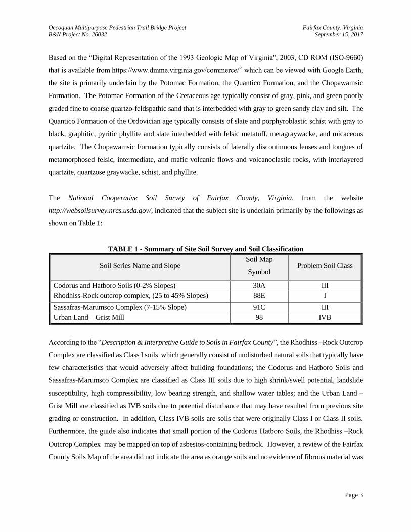
The National Cooperative Soil Survey of Fairfax County, Virginia, from the website
http://websoilsurvey.nrcs.usda.gov/, indicated that the subject site is underlain primarily by the followings as
shown on Table 1:
TABLE 1 - Summary of Site Soil Survey and Soil Classification
Soil Series Name and Slope Soil Map
Symbol Problem Soil Class
Codorus and Hatboro Soils (0-2% Slopes) 30A III
Rhodhiss-Rock outcrop complex, (25 to 45% Slopes) 88E I
Sassafras-Marumsco Complex (7-15% Slope) 91C III
Urban Land – Grist Mill 98 IVB
According to the “Description & Interpretive Guide to Soils in Fairfax County”, the Rhodhiss –Rock Outcrop
Complex are classified as Class I soils which generally consist of undisturbed natural soils that typically have
few characteristics that would adversely affect building foundations; the Codorus and Hatboro Soils and
Sassafras-Marumsco Complex are classified as Class III soils due to high shrink/swell potential, landslide
susceptibility, high compressibility, low bearing strength, and shallow water tables; and the Urban Land –
Grist Mill are classified as IVB soils due to potential disturbance that may have resulted from previous site
grading or construction. In addition, Class IVB soils are soils that were originally Class I or Class II soils.
Furthermore, the guide also indicates that small portion of the Codorus Hatboro Soils, the Rhodhiss –Rock
Outcrop Complex may be mapped on top of asbestos-containing bedrock. However, a review of the Fairfax
County Soils Map of the area did not indicate the area as orange soils and no evidence of fibrous material was
Occoquan Multipurpose Pedestrian Trail Bridge Project Fairfax County, Virginia
B&N Project No. 26032 September 15, 2017
Page 4
observed during visual classification of the jar samples. A copy of the soil survey and aerial image from the
National Cooperative Soil Survey for the site is shown in Figure 4 in Appendix A.
IV. SCOPE OF THE FIELD EXPLORATION
Conclusions and recommendations contained in this report are based on the results of two (2) soil test borings
drilled across the site, and evaluation of soil samples obtained from these borings. Due to steepness of slope
at the location of proposed south abutment and existence of silt fences, boring Q-1 was offset and redrilled 20
feet south and additional hand auger borings (HA series) were performed in the vicinity of proposed south
abutment.
The test borings were utilized to provide both visual identification and engineering properties of soil
underlying the site. Drilling was accomplished with a CME 45C rubber track-mounted drill rig utilizing 3-
1/4 inch- inside-diameter hollow-stem augers. Representative soil samples were obtained by means of the
split-barrel sampling procedure according to ASTM D-1586-84 methods. In the split-barrel sampling
procedure, a 2-inch-outside-diameter split-barrel sampler is driven into the soil a distance of 18 or 24 inches
by means of a 140-pound hammer falling freely a distance of 30 inches. After an initial seating interval of 6
inches, the number of blows required to drive the sampler through a 12-inch interval is termed the Standard
penetration test (SPT) resistance or N-value. The SPT value can be used to provide an indication of the in-
place relative density of cohesionless soils or the consistency of cohesive soils. Soil samples obtained by
conducting this test were used in the field to visually classify the soil types.
The subsurface conditions encountered at the boring locations are shown on the test boring logs in Appendix
B. These test boring logs represent our interpretation of the subsurface conditions based on visual examination
of field samples by a geotechnical engineer. The lines designating the interfaces between various strata on
the test boring logs represent the approximate interface locations. However, the actual transitions between
strata may be gradual. Water levels shown on the test boring logs represent the conditions only at the time of
our exploration, unless otherwise stated. The approximate locations of the borings are shown on the Boring
Location Plans (Figure 3) in Appendix A.
Occoquan Multipurpose Pedestrian Trail Bridge Project Fairfax County, Virginia
B&N Project No. 26032 September 15, 2017
Page 5
V. SUBSURFACE CONDITIONS
A. Stratification
The generalized subsurface stratification was extrapolated from the results of the two (2) soil test borings.
The reader is referred to the Test Boring Logs for the detailed subsurface conditions encountered for each of
the borings drilled. The various soil strata encountered on the site were in general compliance with the
geological formation and history of the region.
The presented stratification of the different layers is based on our visual observations, and geologic origin. In
general, the soils encountered in the area of the proposed development can be designated and summarized in
the stratum presented below.
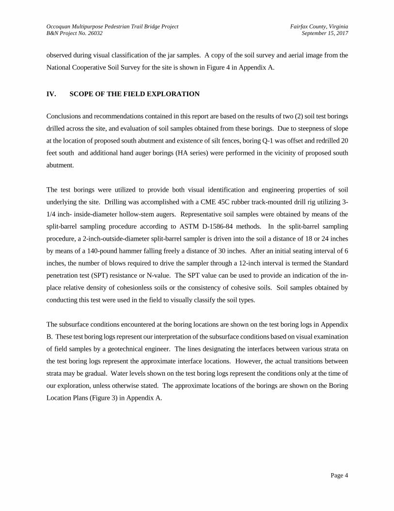
STRATUM A:
Stratum A consisted of residual soils that were sampled as very soft to hard gray, brown
and dark brown SILT (ML) with varying amounts of sand; loose to medium dense
yellowish brown, reddish brown and dark brown fine to medium silty SAND (SM) with
varying amounts of rock fragments. Stratum A was encountered below a 2 inches and 6
inches thick topsoil layer in soil test boring Q-1 and Q-2 and measured in thickness by 3.8
feet and 18.0 feet in these soil test borings, respectively. SPT resistances in Stratum A
generally ranged between WOH and 46 blows per foot (bpf).
STRATUM B:
Stratum B generally consisted of WEATHERED ROCK, sampled as gray and gray brown
sandy silt. Stratum B was encountered beneath Stratum A in soil test boring Q-1 and was
not encountered in soil test boring Q-2. Stratum B was measured to be 3.9 feet in thickness
and extended through the boring termination depth in soil test boring Q-1. WEATHERED
ROCK is defined for engineering purposes as residual material that retains the relict
structure of the parent bedrock and exhibits SPT resistances consistently in excess of 60
bpf. Refusal is defined as 50 blows for 1 inch or less penetration. It should be noted that
weathering that reduces intact rock to weathered rock does not necessarily occur uniformly
in any direction. As a result, intact rock can be encountered and should be anticipated in
the weathered rock zone. As a general rule, drilling equipment similar to that used for this
exploration can advance augers further into material than can be excavated with reasonable
effort by track-mounted backhoe.
It should be noted that the stratigraphy inferred from the boring logs is approximate. Actual changes between
material types (strata) may occur abruptly, more gradually, or at slightly different elevations than those
depicted. Soil areas and groundwater conditions between borings may vary from conditions observed at each
boring location. Furthermore, the borings depict the conditions only during the time of their excavation. Some
conditions, particularly groundwater levels, will fluctuate seasonally.
Occoquan Multipurpose Pedestrian Trail Bridge Project Fairfax County, Virginia
B&N Project No. 26032 September 15, 2017
Page 6
B. Groundwater Conditions
Water levels were measured in our soil test borings at the time of drilling, and as indicated after a stabilization
period as noted in Appendix B on the soil test boring records. Groundwater was encountered at the time of
drilling at depth of 9.1 feet in soil test borings Q-2. Groundwater was not encountered at the time of drilling
in the soil test borings Q-1. After a stabilizing period (casing pull-out), no groundwater was encountered at
any of soil test borings. Please note that no 24 hr. water level readings were obtained at any of soil test borings
and borings were backfilled upon completion.
Cave-in depths were also measured in each of the soil test borings at depths ranging from 3.6 to 6.2 feet bgs.
Please note that cave-in depths where groundwater was not encountered may be indicative of groundwater
movement. Fluctuations in groundwater levels may occur seasonally and vary depending on factors such as
precipitation, surface run-off, evaporation, construction activity, and other site-specific factors. Since such
variations are anticipated, design drawings and specifications should accommodate such possibilities, and
construction planning should be based on the assumption that variations can occur. Local perched
groundwater conditions could develop at locations where clays and silts are present.
VI. GEOTECHNICAL RECOMMENDATIONS
The recommendations provided in this report are based on the previously discussed project information, our
observations at the site, interpretation of the field data obtained during the subsurface explorations performed
on August 25, 2017, our experience with similar subsurface conditions, and engineering analysis. If the
proposed construction scheme should vary from that previously described, then B&N should be contacted and
provided with the opportunity to review these recommendations. The proposed construction of the pedestrian
bridge appears feasible subject to the recommendations contained herein.
A. Foundation
Helical Piers
Based on the information that was provided to us, we understand that the prefabricated pedestrian trail bridge
will be designed to bear on a deep foundation system consisting of a concrete abutment supported by a row
of helical piers which are also known as screw piles. Typical helical pier consist of a lead section with one or
more helices welded to a steel shaft in order to provide the needed bearing capacity. Load is transferred from
Occoquan Multipurpose Pedestrian Trail Bridge Project Fairfax County, Virginia
B&N Project No. 26032 September 15, 2017
Page 7
the shaft to the soil through these bearing plates. The helices are spaced at distances far enough apart that
they function independently as individual bearing elements; consequently, the capacity of a particular helix
on a helical anchor/pile shaft is not influenced by the helix above or below it. The piers are screwed into the
ground with a hydraulic torque motor, and extensions without helixes are added during driving until the
required torque is achieved. Based on the soils encountered at the site we believe that a properly designed
and installed helical pier system will be suitable to support the proposed pedestrian trail bridge. Each helical
pier should be designed with the uppermost helix to bear at least five feet in the medium dense silty sand of
stratum A. However, we understand that minimum embedment depth may not be reached at areas close to
south abutment due to shallow weathered rock elevations. Therefore, alternate foundation systems, if
necessary, are recommended in following section to support the pedestrian bridge. The piers may be designed
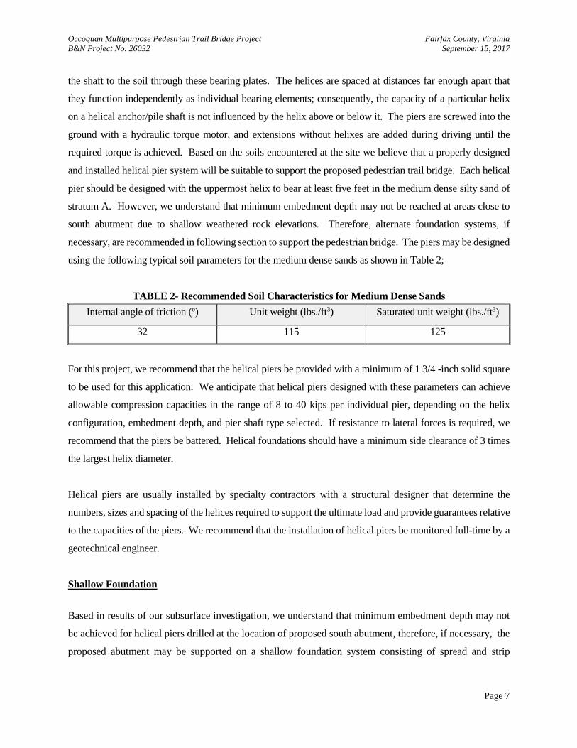
using the following typical soil parameters for the medium dense sands as shown in Table 2;
TABLE 2- Recommended Soil Characteristics for Medium Dense Sands
Internal angle of friction (o) Unit weight (lbs./ft3) Saturated unit weight (lbs./ft3)
32 115 125
For this project, we recommend that the helical piers be provided with a minimum of 1 3/4 -inch solid square
to be used for this application. We anticipate that helical piers designed with these parameters can achieve
allowable compression capacities in the range of 8 to 40 kips per individual pier, depending on the helix
configuration, embedment depth, and pier shaft type selected. If resistance to lateral forces is required, we
recommend that the piers be battered. Helical foundations should have a minimum side clearance of 3 times
the largest helix diameter.
Helical piers are usually installed by specialty contractors with a structural designer that determine the
numbers, sizes and spacing of the helices required to support the ultimate load and provide guarantees relative
to the capacities of the piers. We recommend that the installation of helical piers be monitored full-time by a
geotechnical engineer.
Shallow Foundation
Based in results of our subsurface investigation, we understand that minimum embedment depth may not
be achieved for helical piers drilled at the location of proposed south abutment, therefore, if necessary, the
proposed abutment may be supported on a shallow foundation system consisting of spread and strip
Occoquan Multipurpose Pedestrian Trail Bridge Project Fairfax County, Virginia
B&N Project No. 26032 September 15, 2017
Page 8
footings. Based on the existing site and subsurface conditions, we recommend that footings be designed to
bear either on Residual soils of Stratum A or Weathered Rock of Stratum B with an allowable bearing
pressure of 3.0 kips and 4.0 kips per square foot (ksf) respectively. The allowable bearing pressures
recommended are based on correlations made previously between standard penetration test resistances, the
performance of foundations supported by soils similar to those at this site for this project. We recommend
that the subgrade soils be evaluated by a geotechnical engineer to determine whether they are capable of
supporting the design bearing pressure.
The allowable bearing pressures recommended are based on correlations made previously between standard
penetration test resistances, the performance of foundations supported by soils similar to those at this site, and
preliminary settlement analyses performed for this project. Maximum total settlements are anticipated to be
on the order of 1 inch, with maximum differential settlements on the order of 1/2 inch, if constructed in
accordance with standard engineering practice.
Some undercutting and replacement of loose, soft, organic, or unsuitable soils may be necessary for footings
bearing on or below existing grades. If unsuitable soils are encountered during construction at the foundation
subgrade elevation, the footing should either be lowered to suitable low-plasticity natural soil, or removed
entirely and replaced with compacted low-plasticity soil meeting the compacted fill requirements of this report
or lean concrete.
B. Abutment Walls
Based on the information that was provided to us, we understand that two concrete abutments will be
constructed as part of supporting system for the pedestrian trail bridge at both north and south sides of the
creek. The proposed abutment wall must also be designed to withstand lateral soil pressure. Where wall
corners are fixed and rotation is not desired or permitted, they should be designed to withstand an at-rest earth
pressure condition. A coefficient of at-rest earth pressure (Ko = horizontal stress/vertical stress) of 0.5 is
recommended for walls designed to resist at-rest earth pressures that assume no lateral movement. With an
assumed total unit weight of backfill of approximately 120 pounds per cubic foot (pcf), the walls should
support an equivalent hydrostatic pressure of approximately 60 psf per foot of wall height.
The abutment wall may also be designed using active earth pressures if rotation of the walls will be permitted.
With an active earth pressure coefficient of 0.33 and an assumed backfill soil unit weight of 120 pcf, an
Occoquan Multipurpose Pedestrian Trail Bridge Project Fairfax County, Virginia
B&N Project No. 26032 September 15, 2017
Page 9
equivalent fluid pressure of 40 psf per foot of wall height should be used in the design. Abutment wall corners
should be designed using the at-rest earth pressure described in the previous paragraph.
In order to allow for future excavations for utilities, we recommend that the passive pressure at the toe of
abutment wall be neglected in design. Resistance to sliding should be provided by friction resistance at the
base of the abutment wall. A coefficient of friction against sliding of 0.35 should be used in the design of the
abutment wall bearing on compacted structural FILL or the residual soils of Stratum A. For walls footings
bearing on weathered rock of Stratum B coefficient of friction of 0.58 is recommended.
Abutments Backfill
The abutments should be backfilled with select backfill consisting of VDOT 21A/21B, or select material
Type I with a minimum CBR value of 30 and should be compacted in accordance with Sections 303 and
305 of the VDOT Road and Bridge Specifications, Latest Edition. The zone of select backfill should be
constructed in accordance with Section 17.3 of the Volume V - Part 2 – Design Aids of the VDOT Structure
and Bridge Manuals.
C. Site Classification for Seismic Design
Site classification for seismic design was determined in accordance with Section 1613 of the International
Building Code 2009. Based on the subsurface conditions encountered, the site should be classified as Site
Class D.
VII. CONSTRUCTION RECOMMENDATIONS
A. Site Preparation
Prior to foundation construction and earth fill placement, all topsoil, vegetation, debris, and surface soils
containing organic material should be removed from the construction area and either wasted from the site or
used as topsoil in areas to be landscaped. We estimate up to 6 inches of stripping may be required for site
clearing. Any voids created due to stump removal should be carefully backfilled with compacted fill in areas
where planned foundations are at or near existing ground surface. Stripping operations should extend at least
10 feet outside structures where fill will be placed. During the stripping and rough grading, positive surface
drainage should be maintained to prevent the accumulation of water. If the exposed subgrade becomes
Occoquan Multipurpose Pedestrian Trail Bridge Project Fairfax County, Virginia
B&N Project No. 26032 September 15, 2017
Page 10
excessively wet or frozen, or if conditions are encountered different from those described previously in this
report, the geotechnical engineer should be notified.
We recommend that the proposed subgrade in fill areas be proofrolled to detect unsuitable soil conditions. If
proofrolling is not feasible, we recommend using hand augers and dynamic cone penetration (DCP) tests
during construction to verify the suitability of the subgrades. Areas that do not proofroll successfully or
provide adequate bearing should be undercut to firmer soils, and the undercut excavation backfilled using
compacted, engineered fill.
The exposed subgrades should be observed and documented by the geotechnical engineer. If unsuitable
conditions are encountered at the subgrade level, recommendations for dealing with the conditions should be
provided to the owner's representative by the geotechnical engineer. Any soft or loose soils encountered
during the site preparation, as determined by the geotechnical engineer, should be either improved in place or
undercut and replaced with compacted fill as detailed in this report. If organic, highly plastic, or excessively
wet soils are encountered during site preparation, they should be excavated and replaced with compacted fill.
Proper sedimentation and erosion controls should be implemented according to the approved grading plans
prior to commencement of site work. Grading should be planned to limit ponding of water and soil
disturbance. On site soils are considered suitable for cut and fill slopes of up to 3H:1V or flatter. Additional
analysis may be required if steeper cut and fill slopes are necessary.
B. Foundation Construction
We recommend that the helical pier foundation system be installed by a trained and certified installer using
site-specific approved construction documents and the manufacturer’s written installation documents. The
piers should be installed using a rotary hydraulic machine that is capable of exerting a torsional moment that
exceeds the maximum specified installation torque by at least 10 percent. In addition, an axial force should
be applied on top of the shaft such that the pier penetrates into the underlying soils at a rate of approximately
3 inches per revolution. During the installation of the pier, the contractor should have a torsional resistance
machine capable of measuring the torque to an accuracy of plus or minus 10 percent of the minimum specified
effective torsional resistance termination criterion.
Close observation and monitoring by a certified inspector working under close supervision with the
Occoquan Multipurpose Pedestrian Trail Bridge Project Fairfax County, Virginia
B&N Project No. 26032 September 15, 2017
Page 11
geotechnical engineer, who is familiar with the subsurface conditions at the site and has considerable
experience with helical pier installation procedures, is considered necessary during construction in order to
confirm that the piers are installed satisfactorily to meet the design intent and criteria. The inspector is
responsible for observing all work performed during helical pier installation. During helical pier
installation, the inspector should:
Verify that the torque indicator that is being used has been calibrated within the past 12 months.
Verify that rotational speed between 5 and 25 revolutions per minute is maintained.
Verify that pier is moving between 2 ½ to 3 ½ inches per revolution, especially when torque readings
are taken.
Verify that pile, drive tool, and drive motor are in alignment.
Ensure that pile maximum torque rating is not exceeded.
Verify that extension section with helices are added in the proper sequence.
Record torque readings in increments no greater than 5 feet.
Verify that tip embedment and torsional resistance readings meet or exceed the termination criteria
before terminating installation.
Foundation Construction – Shallow Foundation
Exposure to the environment may weaken the soils at the footing bearing level if the foundation excavations
remain open for too long a time. Therefore, foundation concrete should be placed the same day that
excavations are dug. If the bearing soils are softened by surface water intrusion or exposure, the softened soils
must be removed from the foundation excavation bottom immediately prior to placement of concrete. Care
should be exercised during winter months to prevent freezing of subgrade soils and backfill prior to or after
placement of concrete. Foundation concrete should not be placed on frozen or saturated subgrades. If soft,
highly plastic, or expansive soils classified as CH and/or MH are encountered during construction, the footing
should be either lowered to suitable low-plasticity natural soil, or undercut entirely and replaced with
compacted low-plasticity soil meeting the requirements of the Compacted Fill Section of this report or lean
concrete.
The geotechnical engineer should observe the foundation excavations immediately prior to concrete
placement. The foundation bearing areas should be level or suitably benched and be free of loose soil, ponded
water, and debris prior to the observation. The geotechnical engineer should compare the soils exposed with
Occoquan Multipurpose Pedestrian Trail Bridge Project Fairfax County, Virginia
B&N Project No. 26032 September 15, 2017
Page 12
those encountered in the soil test borings, and then document the results. Any significant differences should
be brought to the attention of the owner's representative along with appropriate recommendations.
C. Compacted Fill
Fill materials are expected for bringing areas up to grade or in any undercut areas. Before filling operations
begin, representative samples of each proposed fill material, including onsite material, should be collected
and the samples should be tested and approved by the geotechnical engineer to determine the maximum dry
density (ASTM D698), optimum moisture content (ASTM D698), natural moisture content (ASTM D 2216),
gradation (ASTM D422), and plasticity (ASTM D4318) of the soil. These tests are needed for quality control
during compaction and to determine if the fill material is acceptable. A review of test boring logs indicates
that the in-situ moisture content of the on-site soils was determined to be mostly wet of the optimum moisture
content by more than 2 percent. As such, we do not believe that the onsite soils will be suitable for use as
compacted fill, unless the on-site soils are dried so that the moisture content is within 2 percent of the optimum
moisture content as obtained from the standard Proctor test.
We recommend that areas on which fill are to be placed be scarified prior to fill placement. We recommend
that compacted fill be constructed by spreading acceptable soil in loose layers not more than 8 inches thick.
The soils used within the pedestrian bridge structure or for replacement in any undercut areas should be
compacted in thin lifts up to 8 inches to at least 95 percent of the standard Proctor maximum dry density
(ASTM D 698). The upper 12 inches of fill should be compacted to 98 percent of standard Proctor. The grass
areas should be compacted to 90 percent of standard Proctor.
The moisture content of the fill soils should be maintained within two percentage points of the optimum
moisture content determined from the standard Proctor density tests. Suitable compacted fill for the structure
should be free of deleterious matter and fibrous organic material, classified CL or better per ASTM D2487,
have a liquid limit of less than 45, and a plasticity index of less than 20. The minimum unit weight of the
proposed fill material should be 105 pcf. In addition, structural fill should not contain particles greater than 4
inches in diameter.
Placement and compaction of all structural fills should be monitored and tested by a certified soils technician
under the supervision of the geotechnical engineer. Significant deviations, either from specifications or good
practice, should be brought to the attention of the owner's representative, along with appropriate
Occoquan Multipurpose Pedestrian Trail Bridge Project Fairfax County, Virginia
B&N Project No. 26032 September 15, 2017
Page 13
recommendations. The fill placed should be tested according to ASTM Standards D1556 (sand cone method)
or D6938 (nuclear method) to evaluate the density and moisture content. A minimum of one test per 2000
square feet of material placed should be performed on each lift. However, no fewer than two tests per day
should be performed on each lift. Recommended compaction effort should include the use of vibratory
smooth drum rollers for granular soils, sheeps foot rollers for fine-grained soils. Any areas that do not meet
the compaction specifications should be recompacted to achieve compliance.
The fill should be graded to provide positive surface drainage, and be sealed by a smooth drum roller or tire-
rolled to prevent infiltration or surface runoff into the approved fill layers. If fill placement is interrupted by
inclement weather, the surface of the fill should be retested, and reworked if necessary, prior to placement of
additional material.
It should be noted that the appropriate provisions of the Fairfax County Building Code and current
Occupational Safety & Health Administration (OSHA) regulations should be followed. Excavation deeper
than 4 feet into soil should be sloped as required by OSHA, or properly braced and shored.
D. Construction Water Control
Based on the groundwater levels noted in the soil test borings, extensive site dewatering should not be
required. However, groundwater may be encountered during excavation for the abutments, and temporary
dewatering may be required. The contractor should promptly remove any surface water or groundwater from
the construction site. This has been done effectively on similar construction projects by means of gravity
drainage and sump pumping. If any water is encountered that cannot be easily handled in such a manner, the
geotechnical engineer should be notified.
The groundwater level can vary from the level measured in our borings due to variations in rainfall,
construction activity, surface runoff, and other site-specific factors. Since such variations are anticipated, we
recommend that design drawings and specifications accommodate such possibilities and that construction
planning be based on the assumption that such variations can occur.
Occoquan Multipurpose Pedestrian Trail Bridge Project Fairfax County, Virginia
B&N Project No. 26032 September 15, 2017
Page 14
VIII. ADDITIONAL SERVICES RECOMMENDED
Additional soil and foundation engineering, testing, and consulting services recommended for this phase of
the project are summarized below:
Site Preparation and Proofrolling: A geotechnical engineer or soils technician should be present onsite
after clearing and stripping operations to determine the degree of undercutting necessary or whether further
proofrolling is necessary to prepare the subgrade.
Fill Placement and Compaction: A geotechnical engineer or soils technician should observe any required
filling operations and should conduct sufficient in-place density tests to evaluate whether the specified degree
of fill compaction has been achieved. The geotechnical engineer must observe and approve imported or
borrow materials to be used, and must determine whether the existing moisture contents are suitable.
Concrete: All concrete placements should be monitored and tested by certified field personnel. All structural
concrete and reinforcing steel should be inspected by a certified concrete technician for compliance with
approved plan specifications.
IX. LIMITATIONS
This report has been prepared to aid in the evaluation of this site for the proposed construction. It is considered
that adequate recommendations have been provided to serve as a basis for design and preparation of plans and
specifications. Additional recommendations can be provided as needed.
The analyses and recommendations of this report are based on the information made available to us at the
time of the actual writing of the report and on site conditions, surface and subsurface, that existed at the time
the exploratory test borings were drilled. Further assumption has been made that the exploratory test borings,
in relation to the depth, are representative of conditions across the site. If subsurface conditions are
encountered that differ significantly from those reported herein, Burgess & Niple should be notified
immediately so that the analysis and recommendations can be reviewed and/or revised as necessary.
We have prepared this report in accordance with generally accepted geotechnical engineering practices, and
make no other warranties, either expressed or implied, as to the professional services performed under this
agreement.

Occoquan Multipurpose Pedestrian Trail Bridge Project Fairfax County, Virginia
B&N Project No. 26032 September 15, 2017
Page 15
Our foundation recommendations are subject to confirmation or revision upon review of the final grades,
plans, and specifications covering all details of the proposed construction.

APPENDIX A
FIGURES & TABLES
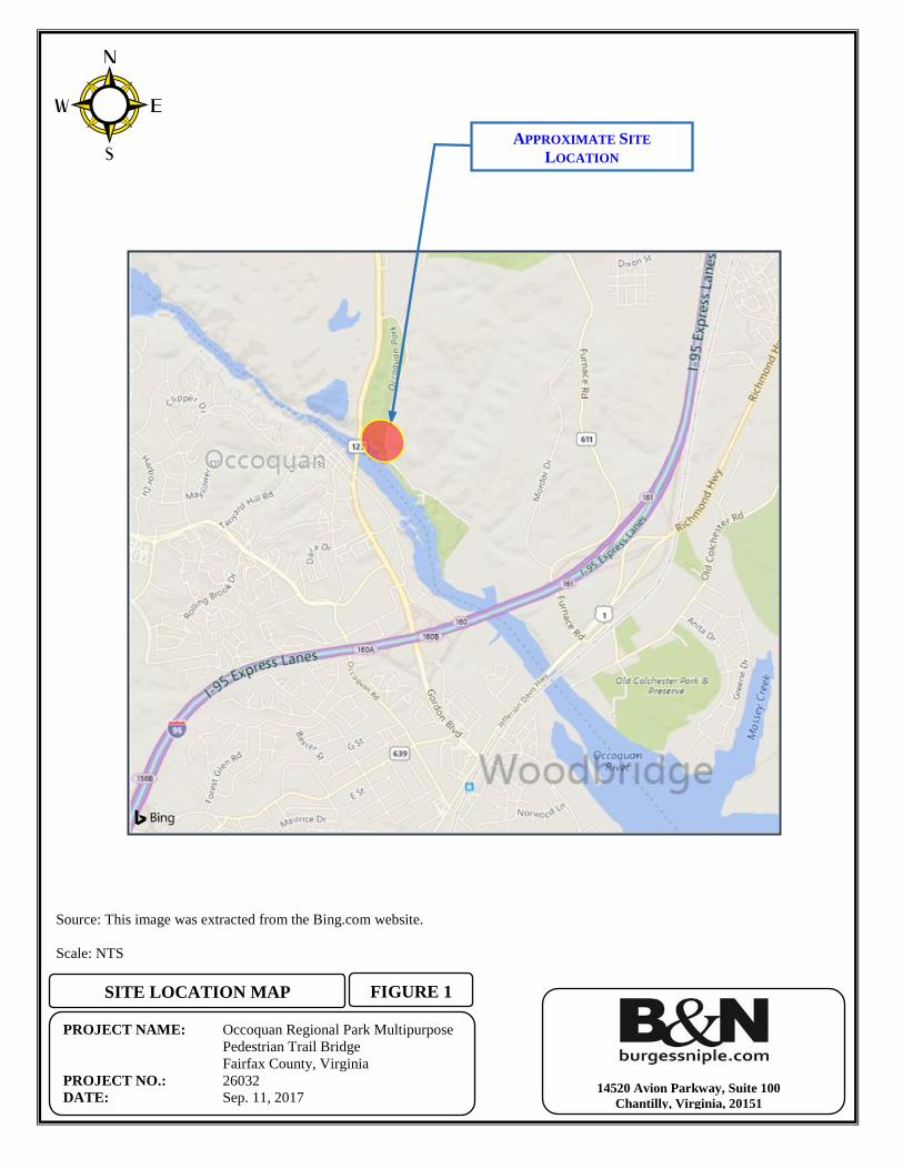
FIGURE 1
PROJECT NAME: Occoquan Regional Park Multipurpose
Pedestrian Trail Bridge
Fairfax County, Virginia
PROJECT NO.: 26032
DATE: Sep. 11, 2017
SITE LOCATION MAP
14520 Avion Parkway, Suite 100
Chantilly, Virginia, 20151
Source: This image was extracted from the Bing.com website.
Scale: NTS
APPROXIMATE SITE
LOCATION
PROJECT NAME: Occoquan Regional Park Multipurpose
Pedestrian Trail Bridge
Fairfax County, Virginia
PROJECT NO.: 26032
DATE: Sep. 11, 2017
TOPOGRAPHIC MAP FIGURE 2
14520 Avion Parkway, Suite 100,
Chantilly, Virginia, 20151
Source: This image was extracted from the “Occoquan Quadrangle, Virginia, 7.5 Minute
Series” topographic map from the U.S. Geological Survey, dated 2016.
Scale: NTS
APPROXIMATE SITE LOCATION
Burgess & Niple, Inc.
14520 Avion Parkway,#100 Chantilly, VA, 20151
PROJECT NAME: Occoquan Regional Park
Multipurpose Pedestrian Bridge
9751 Ox Road, Lorton, VA, 22079
Fairfax County, Virginia
PROJECT NO.: 26032
DATE: Sep. 11, 2017
FIGURE 3
BORING LOCATION PLAN
SB-1
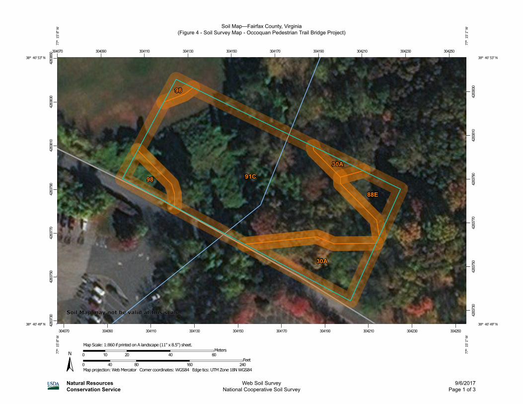
Soil Map—Fairfax County, Virginia(Figure 4 - Soil Survey Map - Occoquan Pedestrian Trail Bridge Project)
Natural ResourcesConservation Service
Web Soil SurveyNational Cooperative Soil Survey
9/6/2017Page 1 of 3
4283
730
4283
750
4283
770
4283
790
4283
810
4283
830
4283
850
4283
730
4283
750
4283
770
4283
790
4283
810
4283
830
304070 304090 304110 304130 304150 304170 304190 304210 304230 304250
304070 304090 304110 304130 304150 304170 304190 304210 304230 304250
38° 40' 53'' N77
° 1
5' 8
'' W38° 40' 53'' N
77° 1
5' 1
'' W
38° 40' 49'' N
77° 1
5' 8
'' W
38° 40' 49'' N
77° 1
5' 1
'' W
N
Map projection: Web Mercator Corner coordinates: WGS84 Edge tics: UTM Zone 18N WGS840 40 80 160 240
Feet0 10 20 40 60
MetersMap Scale: 1:860 if printed on A landscape (11" x 8.5") sheet.
Soil Map may not be valid at this scale.
MAP LEGEND MAP INFORMATION
Area of Interest (AOI)Area of Interest (AOI)
SoilsSoil Map Unit Polygons
Soil Map Unit Lines
Soil Map Unit Points
Special Point FeaturesBlowout
Borrow Pit
Clay Spot
Closed Depression
Gravel Pit
Gravelly Spot
Landfill
Lava Flow
Marsh or swamp
Mine or Quarry
Miscellaneous Water
Perennial Water
Rock Outcrop
Saline Spot
Sandy Spot
Severely Eroded Spot
Sinkhole
Slide or Slip
Sodic Spot
Spoil Area
Stony Spot
Very Stony Spot
Wet Spot
Other
Special Line Features
Water FeaturesStreams and Canals
TransportationRails
Interstate Highways
US Routes
Major Roads
Local Roads
BackgroundAerial Photography
The soil surveys that comprise your AOI were mapped at1:12,000.
Warning: Soil Map may not be valid at this scale.
Enlargement of maps beyond the scale of mapping can causemisunderstanding of the detail of mapping and accuracy of soilline placement. The maps do not show the small areas ofcontrasting soils that could have been shown at a more detailedscale.
Please rely on the bar scale on each map sheet for mapmeasurements.
Source of Map: Natural Resources Conservation ServiceWeb Soil Survey URL:Coordinate System: Web Mercator (EPSG:3857)
Maps from the Web Soil Survey are based on the Web Mercatorprojection, which preserves direction and shape but distortsdistance and area. A projection that preserves area, such as theAlbers equal-area conic projection, should be used if moreaccurate calculations of distance or area are required.
This product is generated from the USDA-NRCS certified data asof the version date(s) listed below.
Soil Survey Area: Fairfax County, VirginiaSurvey Area Data: Version 13, Sep 27, 2016
Soil map units are labeled (as space allows) for map scales1:50,000 or larger.
Date(s) aerial images were photographed: May 3, 2015—Feb22, 2017
The orthophoto or other base map on which the soil lines werecompiled and digitized probably differs from the backgroundimagery displayed on these maps. As a result, some minorshifting of map unit boundaries may be evident.
Soil Map—Fairfax County, Virginia(Figure 4 - Soil Survey Map - Occoquan Pedestrian Trail Bridge Project)
Natural ResourcesConservation Service
Web Soil SurveyNational Cooperative Soil Survey
9/6/2017Page 2 of 3
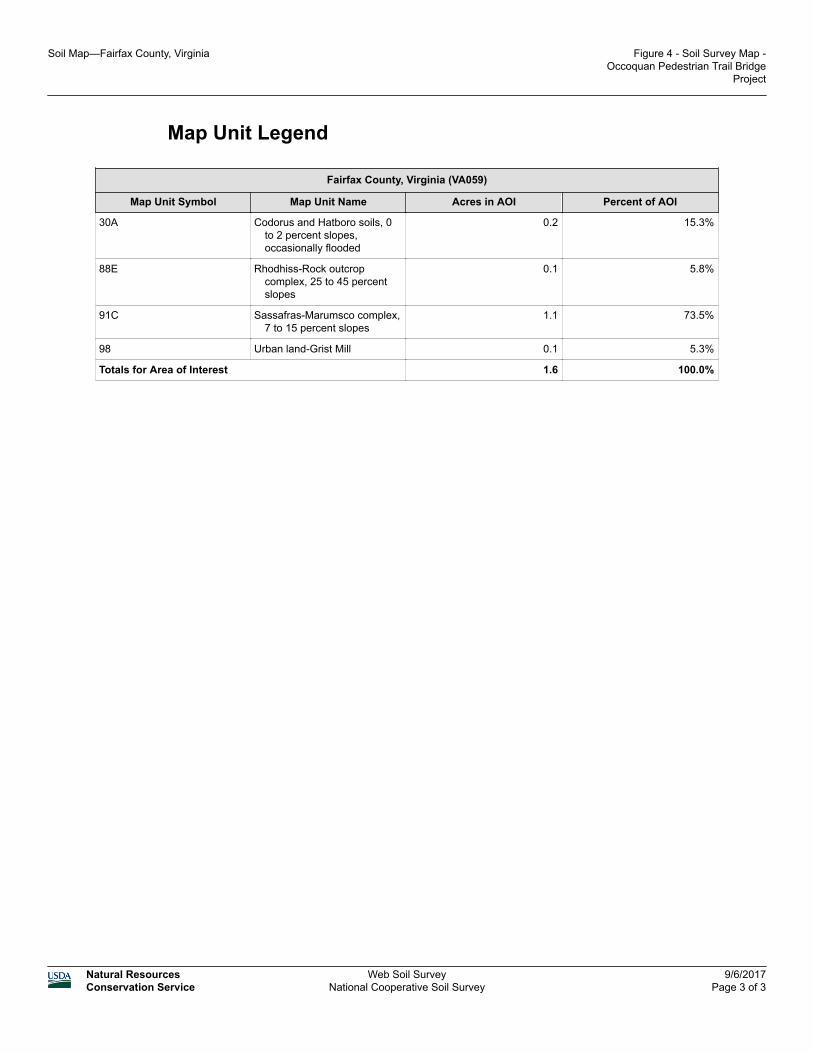
Map Unit Legend
Fairfax County, Virginia (VA059)
Map Unit Symbol Map Unit Name Acres in AOI Percent of AOI
30A Codorus and Hatboro soils, 0to 2 percent slopes,occasionally flooded
0.2 15.3%
88E Rhodhiss-Rock outcropcomplex, 25 to 45 percentslopes
0.1 5.8%
91C Sassafras-Marumsco complex,7 to 15 percent slopes
1.1 73.5%
98 Urban land-Grist Mill 0.1 5.3%
Totals for Area of Interest 1.6 100.0%
Soil Map—Fairfax County, Virginia Figure 4 - Soil Survey Map -Occoquan Pedestrian Trail Bridge
Project
Natural ResourcesConservation Service
Web Soil SurveyNational Cooperative Soil Survey
9/6/2017Page 3 of 3
APPENDIX B
FIELD OPERATIONS
Soil Type
Soil
Component
Descriptive
Term
Boulder Major
(Uppercase SILT
Cobble letters) CLAY
SAND
Gravel GRAVEL
- Coarse
- Fine Secondary
(Adjective) Clayey or Silty
Sand Sandy or Gravelly
- Coarse
- Medium (with) Clay or Silt
- Fine Sand or Gravel
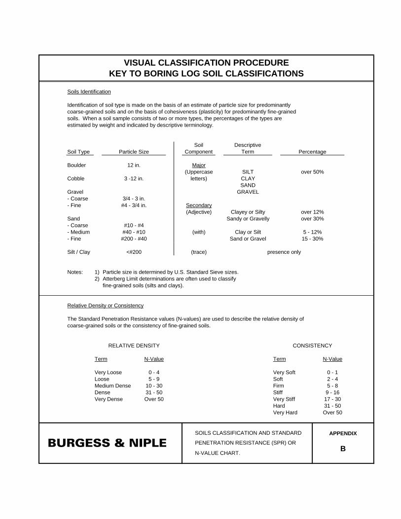
soils. When a soil sample consists of two or more types, the percentages of the types are
estimated by weight and indicated by descriptive terminology.
Particle Size Percentage
VISUAL CLASSIFICATION PROCEDURE
KEY TO BORING LOG SOIL CLASSIFICATIONS
Soils Identification
Identification of soil type is made on the basis of an estimate of particle size for predominantly
coarse-grained soils and on the basis of cohesiveness (plasticity) for predominantly fine-grained
12 in.
3 -12 in.
3/4 - 3 in.
#4 - 3/4 in.
over 50%
over 12%
over 30%
5 - 12%
15 - 30%
#10 - #4
#40 - #10
#200 - #40
Silt / Clay (trace)
Notes: 1)
2)
APPENDIX
B N-VALUE CHART.
PENETRATION RESISTANCE (SPR) OR
SOILS CLASSIFICATION AND STANDARD
presence only
Particle size is determined by U.S. Standard Sieve sizes.
Atterberg Limit determinations are often used to classify
fine-grained soils (silts and clays).
The Standard Penetration Resistance values (N-values) are used to describe the relative density of
<#200
coarse-grained soils or the consistency of fine-grained soils.
Relative Density or Consistency
RELATIVE DENSITY
Term N-Value N-Value
CONSISTENCY
Term
Very Dense
0 - 4
5 - 9
10 - 30
31 - 50
Over 50
Very Loose
Loose
Medium Dense
Dense
Very Soft
Soft
Firm
0 - 1
2 - 4
5 - 8
Very Stiff
Hard
Very Hard
9 - 16
17 - 30
31 - 50
Over 50
Stiff
0
4
8
12
16
20
24
18.0 17.8
14.0
10.1
T
ML
W
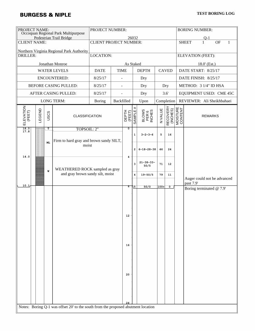
TOPSOIL: 2"
Firm to hard gray and brown sandy SILT,moist
WEATHERED ROCK sampled as grayand gray brown sandy silt, moist
1
2
3
4
5
3-2-3-6
6-18-28-38
21-38-33-50/5
19-50/5
50/0
5
46
71
79
100+
16
24
12
11
0
Auger could not be advancedpast 7.9'
Boring terminated @ 7.9'
PROJECT NAME:Occoquan Regional Park Multipurpose
Pedestrian Trail Bridge
PROJECT NUMBER:
26032
BORING NUMBER:
Q-1CLIENT NAME:
Northern Virginia Regional Park Authority
CLIENT PROJECT NUMBER: SHEET 1 OF
DRILLER:
Jonathan Monroe
LOCATION:
As Staked
ELEVATION (FEET):
18.0' (Est.)
WATER LEVELS DATE TIME DEPTH CAVED DATE START: 8/25/17
ENCOUNTERED: 8/25/17 - Dry DATE FINISH: 8/25/17
BEFORE CASING PULLED: 8/25/17 - Dry Dry METHOD: 3 1/4" ID HSA
AFTER CASING PULLED: 8/25/17 - Dry 3.6' EQUIPMENT USED: CME 45C
LONG TERM: Boring Backfilled Upon Completion REVIEWER: Ali Sheikhbahaei
Notes: Boring Q-1 was offset 20' to the south from the proposed abutment location
EL
EV
AT
ION
(FE
ET
)
LE
GE
ND
US
CS
CLASSIFICATION
DE
PT
H(F
EE
T)
SA
MP
LE
#
BL
OW
SP
ER
6IN
CH
ES
N V
AL
UE
RE
CO
VE
RY
(IN
CH
ES
)
MO
IST
UR
EC
ON
TE
NT
REMARKS
BURGESS & NIPLE, INCTEST BORING LOG
1
0
4
8
12
16
20
24
12.5 12.0
4.5
-6.0
T
SM
ML
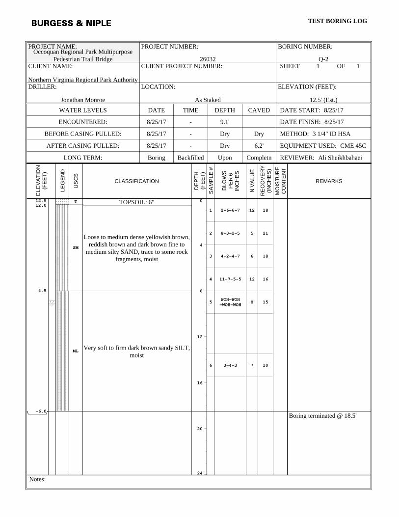
TOPSOIL: 6"
Loose to medium dense yellowish brown,reddish brown and dark brown fine to
medium silty SAND, trace to some rockfragments, moist
Very soft to firm dark brown sandy SILT,moist
1
2
3
4
5
6
2-6-6-7
8-3-2-5
4-2-4-7
11-7-5-5
WOH-WOH-WOH-WOH
3-4-3
12
5
6
12
0
7
18
21
18
16
15
10
Boring terminated @ 18.5'
PROJECT NAME:Occoquan Regional Park Multipurpose
Pedestrian Trail Bridge
PROJECT NUMBER:
26032
BORING NUMBER:
Q-2CLIENT NAME:
Northern Virginia Regional Park Authority
CLIENT PROJECT NUMBER: SHEET 1 OF
DRILLER:
Jonathan Monroe
LOCATION:
As Staked
ELEVATION (FEET):
12.5' (Est.)
WATER LEVELS DATE TIME DEPTH CAVED DATE START: 8/25/17
ENCOUNTERED: 8/25/17 - 9.1' DATE FINISH: 8/25/17
BEFORE CASING PULLED: 8/25/17 - Dry Dry METHOD: 3 1/4" ID HSA
AFTER CASING PULLED: 8/25/17 - Dry 6.2' EQUIPMENT USED: CME 45C
LONG TERM: Boring Backfilled Upon Completn REVIEWER: Ali Sheikhbahaei
Notes:
EL
EV
AT
ION
(FE
ET
)
LE
GE
ND
US
CS
CLASSIFICATION
DE
PT
H(F
EE
T)
SA
MP
LE
#
BL
OW
SP
ER
6IN
CH
ES
N V
AL
UE
RE
CO
VE
RY
(IN
CH
ES
)
MO
IST
UR
EC
ON
TE
NT
REMARKS
BURGESS & NIPLE, INCTEST BORING LOG
1
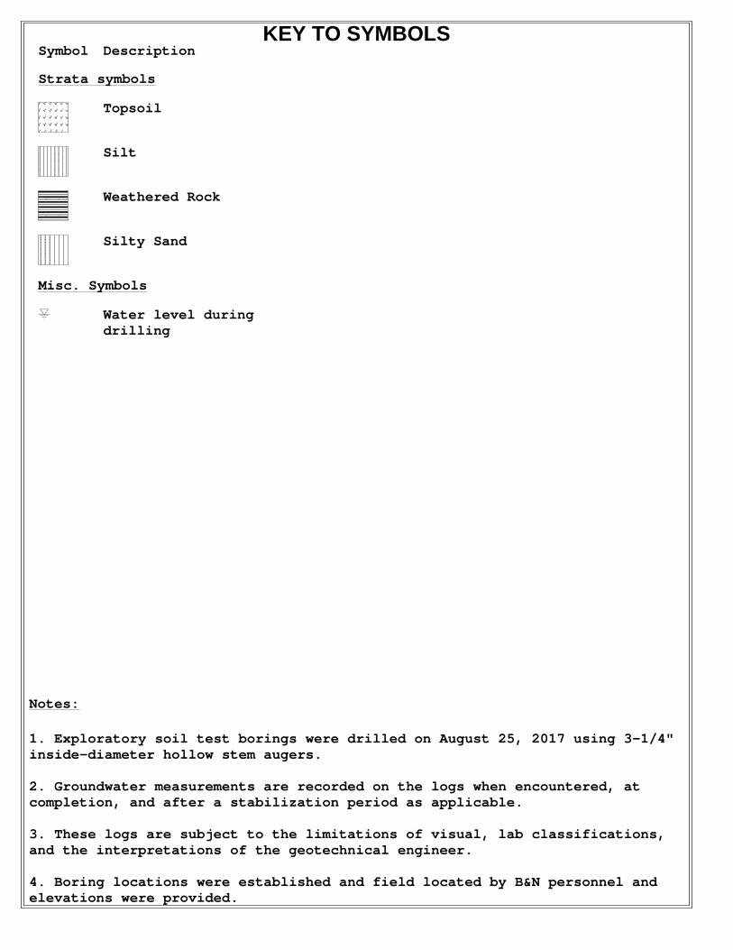
1. Exploratory soil test borings were drilled on August 25, 2017 using 3-1/4"inside-diameter hollow stem augers.
2. Groundwater measurements are recorded on the logs when encountered, atcompletion, and after a stabilization period as applicable.
3. These logs are subject to the limitations of visual, lab classifications,and the interpretations of the geotechnical engineer.
4. Boring locations were established and field located by B&N personnel andelevations were provided.
Notes:
Symbol Description
Strata symbols
Topsoil
Silt
Weathered Rock
Silty Sand
Misc. Symbols
Water level duringdrilling
KEY TO SYMBOLS

RECORD OF HAND AUGER LOG
B&N Project Number 26032
Hand Auger No.: HA-1 Elevation: 11.0’
Depth (ft.) Description
From To
0 2.0’ Rock fragments, Boulders
NOTE: Hand-Auger refusal at 2.0 ft. below ground surface.
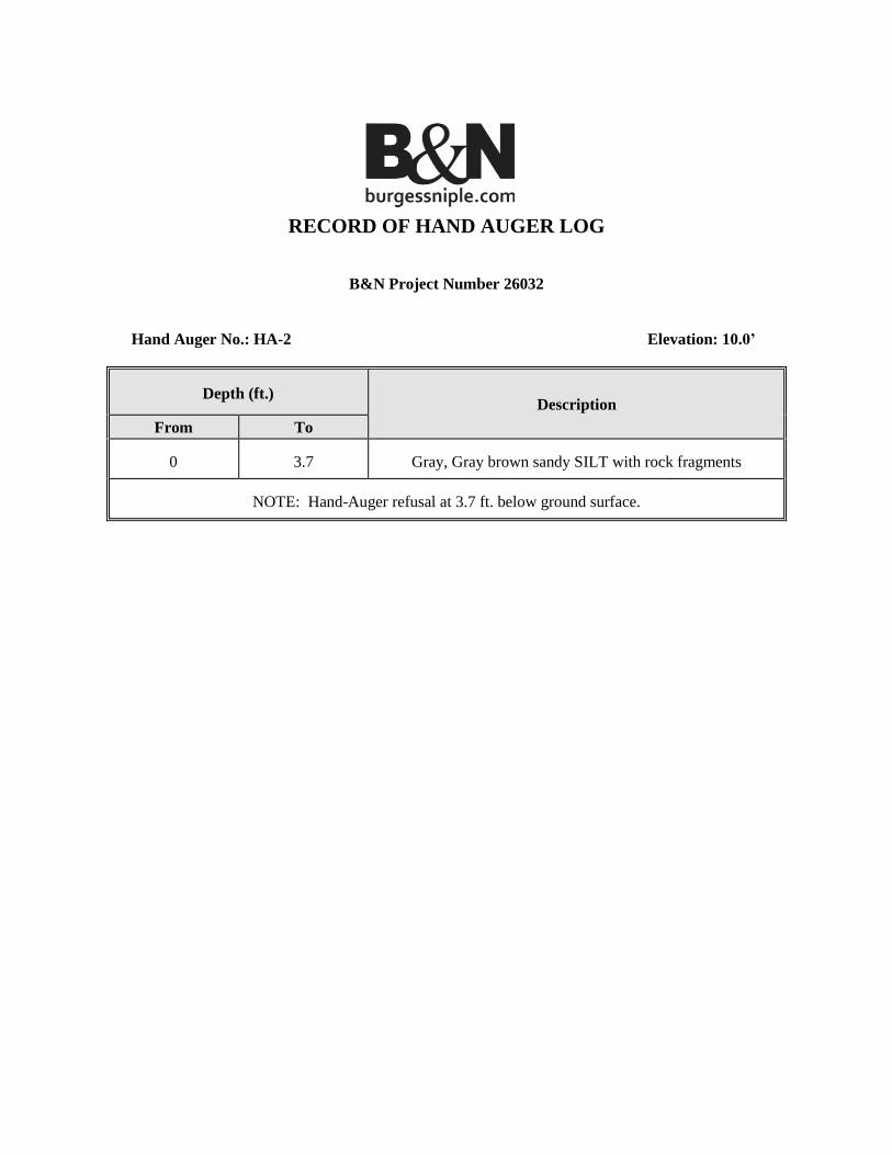
RECORD OF HAND AUGER LOG
B&N Project Number 26032
Hand Auger No.: HA-2 Elevation: 10.0’
Depth (ft.) Description
From To
0 3.7 Gray, Gray brown sandy SILT with rock fragments
NOTE: Hand-Auger refusal at 3.7 ft. below ground surface.
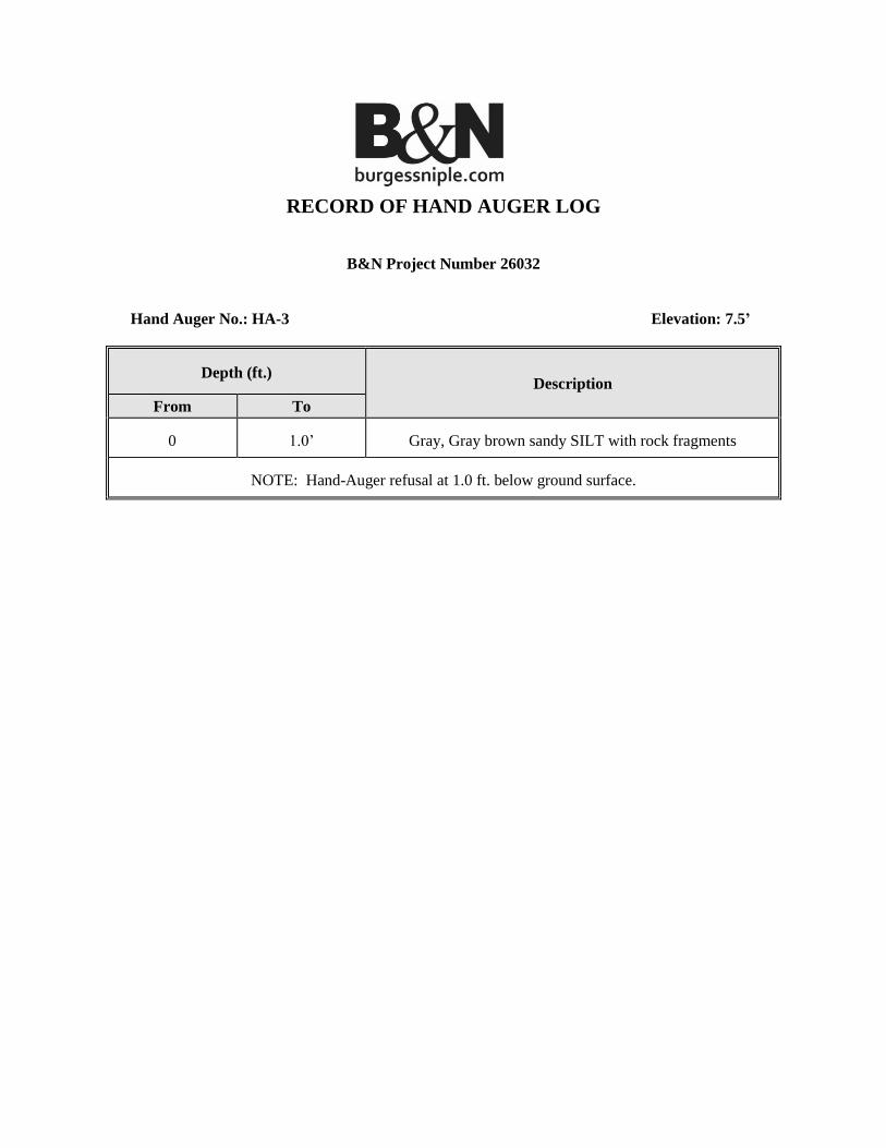
RECORD OF HAND AUGER LOG
B&N Project Number 26032
Hand Auger No.: HA-3 Elevation: 7.5’
Depth (ft.) Description
From To
0 1.0’ Gray, Gray brown sandy SILT with rock fragments
NOTE: Hand-Auger refusal at 1.0 ft. below ground surface.
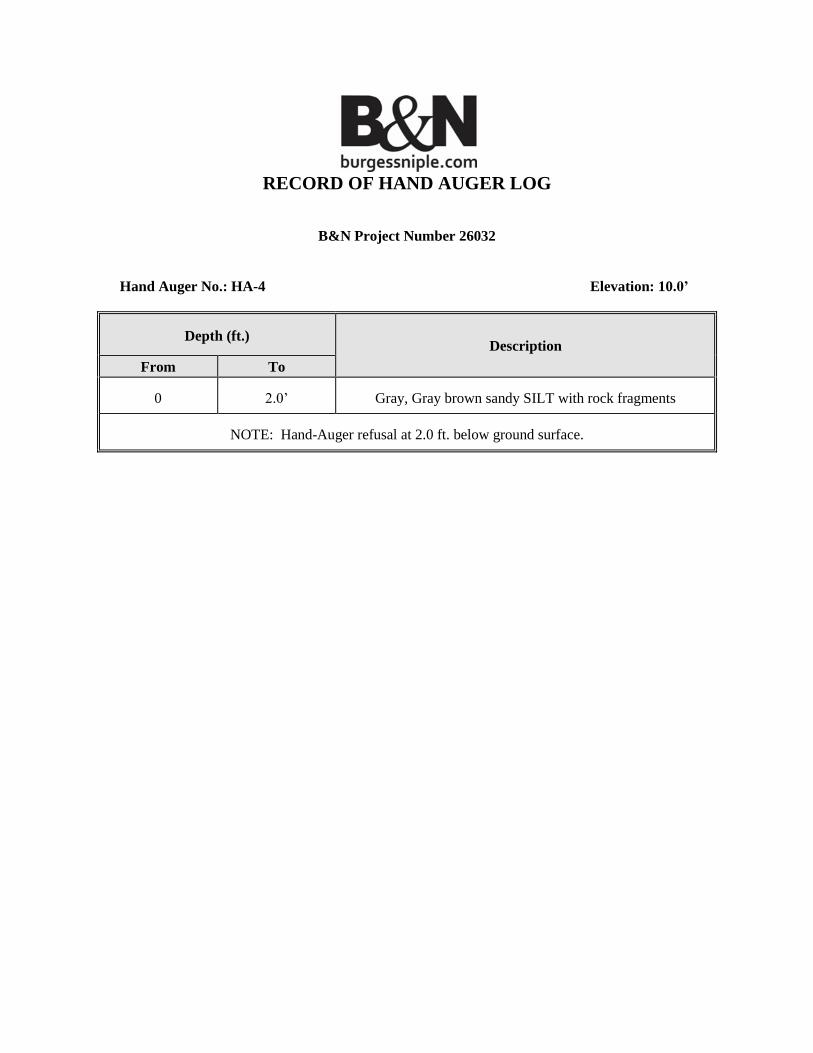
RECORD OF HAND AUGER LOG
B&N Project Number 26032
Hand Auger No.: HA-4 Elevation: 10.0’
Depth (ft.) Description
From To
0 2.0’ Gray, Gray brown sandy SILT with rock fragments
NOTE: Hand-Auger refusal at 2.0 ft. below ground surface.