oceanic vt3...welcome to oceanic and thank you for choosing the vt3 ! it is extremely important that...
TRANSCRIPT

OCEANIC
VT3Operating Manual
(-r04 cover art to be placed on front/back is provided separately)


3
CONTENTS
WARRANTY, NOTICES, DECOMPRESSION MODEL .................................................................................................... 7FCC ID ............................................................................................................................................................................... 8
INTRODUCTION AND GENERAL FEATURES AND DISPLAYS .................................................................................... 9INTERACTIVE CONTROL CONSOLE ..................................................................................................................... 10OPERATING MODE STRUCTURE ........................................................................................................................... 11AUDIBLE ALARM ...................................................................................................................................................... 12SMARTGLO BACKLIGHT ........................................................................................................................................ 14POWER SUPPLY ...................................................................................................................................................... 15BAR GRAPHS ........................................................................................................................................................... 17PC INTERFACE ......................................................................................................................................................... 19SYMBOLS AND ALPHA NUMERIC GRAPHICS ...................................................................................................... 19ALPHA / NUMERIC DISPLAYS ................................................................................................................................ 20
Tank Pressure Display .......................................................................................................................................... 20Depth Displays ...................................................................................................................................................... 20Air Time Remaining Display ................................................................................................................................. 20Date. Time, and Temperature Displays ................................................................................................................ 21FREE Dive Mode Displays ................................................................................................................................... 21
SURFACE SEQUENCE AND OPERATING MODES ..................................................................................................... 23OPERATING MODES ................................................................................................................................................ 24SURFACE MODE ...................................................................................................................................................... 24
NORM (Normal) Surface Main Display ................................................................................................................ 25NORM Surface Main Button Operations .............................................................................................................. 26VT3 Battery Status .............................................................................................................................................. 27Transmitter Status .............................................................................................................................................. 27
SET MODES .............................................................................................................................................................. 28SET F GROUP (FO2) ................................................................................................................................................ 28
Set FO2 for NORM Nitrox Dives .......................................................................................................................... 29

4
CONTENTS (continued)
Set FO2 GAS 1 ..................................................................................................................................................... 31Set FO2 GAS 2 ..................................................................................................................................................... 32Set FO2 GAS 3 ..................................................................................................................................................... 33Set FO2 50% Default ........................................................................................................................................... 34
SET A GROUP (NORM/GAUG ALARMS) ................................................................................................................ 34Set Audible Alarm ................................................................................................................................................. 35Set Depth Alarm ................................................................................................................................................... 36Set EDT (Elapsed Dive Time) Alarm ................................................................................................................... 37Set TLBG (Tissue Loading Bar Graph) Alarm ...................................................................................................... 38Set DTR (Dive Time Remaining) Alarm ................................................................................................................ 39Set Turn Pressure Alarm (TMT1) ......................................................................................................................... 40Set End Pressure Alarm ....................................................................................................................................... 41Set PO2 Alarm ...................................................................................................................................................... 42
SET U GROUP (UTILITIES) ...................................................................................................................................... 43Set Wet Activation ................................................................................................................................................ 44Set Units of Measure ............................................................................................................................................ 45Set NORM Safety Stop ......................................................................................................................................... 46Set Conservative Factor ....................................................................................................................................... 47Set Backlight Duration .......................................................................................................................................... 48Set Sampling Rate ................................................................................................................................................ 49Set TMT1 (Transmitter 1 Link Code) .................................................................................................................... 50Set TMT (Transmitter) 2-3 Use ............................................................................................................................ 52Set TMT2 (Transmitter 2 Link Code) ................................................................................................................... 53Set TMT3 (Transmitter 3 Link Code) ................................................................................................................... 55
SET T GROUP (TIME/DATE) .................................................................................................................................... 57Set Hour Format ................................................................................................................................................... 58Set Time ................................................................................................................................................................ 58Set Date ................................................................................................................................................................ 59
SERIAL NUMBER (VT3) ........................................................................................................................................... 60NORM SURF ALT DISPLAY (SURFACE ALTERNATE) ........................................................................................... 61NORM PLAN MODE .................................................................................................................................................. 61FLY MODE ................................................................................................................................................................. 64SAT MODE (DESATURATE) ..................................................................................................................................... 66

5
CONTENTS (continued)
NORM/GAUG LOG MODE ........................................................................................................................................ 67NORM/GAUG HISTORY MODE ................................................................................................................................ 72OVERVIEW OF DISPLAYED SYMBOLS AND ICONS ............................................................................................ 74
OVERVIEW OF DIVE MODE OPERATION ................................................................................................................... 75POSITIONING OF THE VT3 ..................................................................................................................................... 77
Link Interruption Underwater ................................................................................................................................ 77DIVE TIME REMAINING (DTR) ................................................................................................................................. 78
No Decompression Dive Time Remaining (NDC) ................................................................................................ 79Oxygen Accumulation Time Remaining (OTR) .................................................................................................... 80Air Time Remaining (ATR) .................................................................................................................................... 80Air Time Remaining Alarm .................................................................................................................................... 81
ASCENT RATE ALARM ............................................................................................................................................ 82CONTROL OF DISPLAYS ......................................................................................................................................... 83WET CONTACTS ....................................................................................................................................................... 84
NORM TYPE DIVE MODES ........................................................................................................................................... 85NORM NO DECOMPRESSION DIVE MODE ........................................................................................................... 86
NORM Dive No Deco Safety Stop ....................................................................................................................... 89DECOMPRESSION DIVE MODE ........................................................................................................................ 91
VIOLATION MODES .................................................................................................................................................. 95NORM HIGH PO2 .................................................................................................................................................... 100HIGH OXYGEN ACCUMULATION .......................................................................................................................... 101SUMMARY OF NORM/GAUG WARNING AND ALARM MESSAGES .................................................................. 102
SWITCHING GAS MIXES AND BUDDY PRESSURE CHECK .................................................................................... 103SWITCHING GAS MIXES (NORM ONLY) .............................................................................................................. 104BUDDY PRESSURE CHECK (NORM ONLY) ......................................................................................................... 109
NORM POST DIVE MODES ......................................................................................................................................... 113TRANSITION PERIOD ............................................................................................................................................ 114AFTER THE TRANSITION PERIOD ....................................................................................................................... 116
6
CONTENTS (continued)
GAUGE OPERATING MODE ....................................................................................................................................... 117GAUG SURFACE DISPLAYS .................................................................................................................................. 118GAUG DIVE DISPLAYS .......................................................................................................................................... 119
FREE DIVE OPERATING MODE ................................................................................................................................. 121FREE SURFACE DISPLAYS ................................................................................................................................... 122FREE COUNTDOWN TIMER (CDT) ....................................................................................................................... 124SET FREE CDT ....................................................................................................................................................... 126SET FREE EDT (ELAPSED DIVE TIME) ALARM .................................................................................................. 127SET FREE DEPTH ALARMS .................................................................................................................................. 128FREE DIVE DISPLAYS ............................................................................................................................................ 132FREE DIVE ALARMS .............................................................................................................................................. 133ENTRY INTO DECO DURING A FREE DIVE ......................................................................................................... 136
REFERENCE ................................................................................................................................................................. 137UPLOADING SETTINGS AND DOWNLOADING DATA ........................................................................................ 138
PC Compatibility Requirements .......................................................................................................................... 139CARE AND CLEANING ........................................................................................................................................... 140INSPECTIONS AND SERVICE ............................................................................................................................... 140BATTERY REPLACEMENT .................................................................................................................................... 142INSTALLING A TRANSMITTER ON A REGULATOR ............................................................................................ 148TRANSMITTER COMPATIBILITY WITH NITROX .................................................................................................. 148ALTITUDE SENSING AND ADJUSTMENT ............................................................................................................ 149CHARTS OF NO DECOMPRESSION LIMITS AT ALTITUDE ................................................................................ 150CHART OF OXYGEN EXPOSURE LIMITS ............................................................................................................ 151SPECIFICATIONS ................................................................................................................................................... 152ADDITIONAL INFORMATION PERTAINING TO FREE DIVE MODE .................................................................... 159INSPECTION/ SERVICE RECORD ......................................................................................................................... 160FULL DISPLAY ........................................................................................................................................................ 161OCEANIC WORLD WIDE ....................................................................................................................................... 162
Pay special attention to items markedwith this Warning symbol.

7
LIMITED TWO-YEAR WARRANTYFor details, refer to the Product Warranty Registration Card provided. Register on-line at www.OceanicWorldwide.com
COPYRIGHT NOTICEThis operating manual is copyrighted, all rights are reserved. It may not, in whole or in part, be copied, photocopied,reproduced, translated, or reduced to any electronic medium or machine readable form without prior consent in writingfrom Oceanic / 2002 Design.
VT3 Operating Manual, Doc. No. 12-2705© 2002 Design, 2006
San Leandro, CA USA 94577
TRADEMARK, TRADE NAME, AND SERVICE MARK NOTICEOceanic, the Oceanic logotype, the Oceanic 'O' symbol, VT3, the VT3 logo, Air Time Remaining (ATR), Diver Replace-able Batteries, Graphic Diver Interface, Tissue Loading Bar Graph (TLBG), Pre Dive Planning Sequence (PDPS),SmartGlo, Set Point, Control Console, Turn Gas Alarm, and OceanLog are all registered and unregistered trademarks ,trade names, and service marks of Oceanic. All rights are reserved.
PATENT NOTICEU.S. Patents have been issued, or applied for, to protect the following design features:Air Time Remaining (U.S. Patent no. 4,586,136 and 6,543,444) and Data Sensing and Processing Device (U.S. Patentno. 4,882,678). Set TLBG Alarm and other patents pending. User Setable Display (U.S. Patent no. 5,845,235) isowned by Suunto Oy (Finland).
DECOMPRESSION MODELThe programs within the VT3 simulate the absorption of nitrogen into the body by using a mathematical model. Thismodel is merely a way to apply a limited set of data to a large range of experiences. The VT3 dive computer model isbased upon the latest research and experiments in decompression theory. Still, using the VT3, just as using theU.S. Navy (or other) No Decompression Tables, is no guarantee of avoiding decompression sick-ness, i.e. “the bends.” Every diver’s physiology is different, and can even vary from day to day. No machine canpredict how your body will react to a particular dive profile.

8
WARNING: If your VT3 stops working for any reason while oper-ating as a Dive Computer, it is important that you have anticipatedthis possibility and are prepared for it. This is an important rea-son for not pushing the no decompression and oxygen exposurelimits, and a critical reason to avoid entering decompression. Ifyou dive in situations where your trip would be ruined or yoursafety would be jeopardized by losing the use of your VT3, abackup instrument system is highly recommended.
FCC ID: MH8A
FCC COMPLIANCE:This equipment complies with Part 15 of the FCC Rules. Operation is subject to the following two conditions: 1.) this equipment may notcause harmful interference, and 2.) this equipment must accept any interference received, including interference that may cause undesiredoperation.
FCC INTERFERENCE STATEMENT:This equipment has been tested and found to comply with the limits for an Intentional Radiator, a Class B Digital Device, pursuant to Part15 of FCC Rules, Title 47 of the Code of Federal Regulations. These rules are designed to provide reasonable protection against harmfulinterference in a commercial or residential installation. This equipment generates, uses and can radiate radio frequency energy and, ifnot installed and used in accordance with the instructions, may cause harmful interference to radio communications.
There is no guarantee that interference will not occur in a particular installation. If this equipment does cause interference to radio ortelevision reception, which can be determined by turning the equipment off and on, the user is encouraged to try to correct theinterference by one or more of the following measures:
• Reorient or relocate the receiving antenna.• Increase the separation between the equipment and receiver.• Connect the equipment to an outlet on a circuit different from that to which the receiver is connected.• Consult the dealer or an experienced radio/TV technician.
Warning: Changes or modifications to this unit not expressly approved by Oceanic/2002 Design couldvoid the user's authority to operate the equipment.

9
WARNING: Prior to diving with the VT3, youmust also read and understand the OceanicDive Computer Safety and Reference Manual,Doc. No. 12-2262, which provides ImportantWarnings and Safety Recommendations aswell as general product information.
INTRODUCTIONAND
GENERAL FEATURES AND DISPLAYS

10
INTRODUCTION
Welcome to OCEANIC and thank you for choosing the VT3 !
It is extremely important that you read this Operating Manual in sequence and understandit completely before attempting to use the VT3 as a dive computer.
It is equally important that you read the Oceanic Dive Computer Safety and ReferenceManual (Doc. No. 12-2262) provided with your VT3. It contains information that you mustbecome familiar with prior to diving with your VT3.
Remember that technology is no substitute for common sense, and a dive computer onlyprovides the person using it with data, not the knowledge to use it.
INTERACTIVE CONTROL CONSOLEThe Interactive Control Console consists of 3 Control Buttons that allow you to select modeoptions and access specific information. They are also used to link the Transmitter(s), enterSettings, activate the Backlight, and acknowledge the Audible Alarm.
Throughout this manual they will be referred to as the M, S, and A buttons.
• Left/Front - Mode (M) button• Right/Front - Advance (A) button• Right/Side - Select (S) button
M A
S

11
OPERATING MODE STRUCTURE
The M button is used to access 3 operating Modes (Fig. 1) thatinclude NORM (Normal Air/Nitrox Dive Computer), GAUG(Digital Gauge Mode), and FREE (Free Dive Mode).
The screens of the Main Modes and Sub Modes will remain ondisplay until a button is pressed to access another screen orMode, activate a sequence, or for 2 minutes if no button ispressed.
When Wet Activation is set On, the VT3 will enter the selectedDive Mode upon descent to 5 FT (feet) /1.5 M (meters), regard-less of what surface screen is displayed at the time.
WARNING: When Wet Activation is set OFF, theVT3 must be activated by push button prior tothe first dive of a new series. Commencing adive will not activate Dive Mode unless WetActivation is set ON or the unit is activated.
Entering Settings and Plan Mode are available in NORM SURFMode which also allows access to Battery/Transmitter Status,Fly, Desat, Log, and History Modes. Tank Pressure is displayedif a Transmitter is active and Linked with the VT3.
Fig. 1 - Operating Modes
NORM (Normal Air/Nitrox)
FREE (Mode)
GAUG (Digital Gauge Mode)

12
GAUG Surface Mode allows access to Battery/Transmitter Status, Fly, Log, and HistoryModes. It also displays Tank Pressure.
FREE Mode allows access to sub modes by first accessing NORM Surface Mode. It doesnot display Tank Pressure.
Once a dive is made in GAUG Operating Mode, the VT3 is locked into that Mode for 24hours after the dive.
The VT3 also features 2 modes for use of Transmitter Pressure. A setting allows you tochoose whether Transmitters 2 and 3 are for your use (SELF) or for checking 1 or 2 Bud-dies' Tank Pressure(s). The setting remains fixed until changed in the NORM/GAUG SETU menu.
AUDIBLE ALARMMost warning situations that activate the Audible Alarm while operating in NORM orGAUG Mode cause the VT3 to emit 1 beep per second for 10 seconds, or until the situa-tion is corrected, or it is acknowledged by momentarily pressing and releasing the S button(less than 2 seconds). After being acknowledged and the situation corrected, the Alarmwill sound again upon reentry into the warning situation, or entry into another type ofwarning situation.
FREE Dive Mode has its own set of Alarms which emit 3 short beeps either 1 or 3 timeswhich cannot be acknowledged or set Off.

13
A red LED Warning Light, located on the left side of the housing, is synchronized with theAudible Alarm. It will flash as the Audible Alarm sounds. It will turn Off when the Alarm isacknowledged or the situation is corrected. The Audible and LED will not be active if theAlarm is Set OFF (a group A setting).
Situations that will activate the NORM/GAUG 10 second Alarm include -• Air Time Remaining (ATR) at 5 minutes, then again at 0 minutes.• ATR becomes less than No Deco and O2 Time Remaining for 1 minute.• Turn Pressure at the Set Point selected (Transmitter 1).• End Pressure at the Set Point selected (active Transmitter).• Descent deeper than the Max Depth Set Point selected.• Dive Time Remaining at the Set Point selected.• Elapsed Dive Time at the Set Point selected.• High PO2 of 1.60 ATA or the Set Point selected.• High O2 of 300 OTU (single or daily exposure).• Tissue Loading Bar Graph at the segment Set Point selected.• NORM/GAUG Ascent Rate exceeds 60 FPM (18 MPM) when deeper than 60 FT (18
M), or 30 FPM (9 MPM) at 60 FT (18 M) and shallower.• Loss of the active Transmitter Link signal for more than 15 seconds during a dive.• Entry into Decompression Mode (Deco).• Conditional Violation (above a required Deco Stop Depth for less than 5 minutes).• Delayed Violation (above a required Deco Stop Depth for more than 5 minutes).• Delayed Violation (a Deco Stop Depth greater than 60 FT/18 M is required).• Delayed Violation (Maximum Operating Depth of 330 FT/100 M is exceeded).• A Gas Switch to another tank would expose the diver to PO2 greater than 1.60 ATA.

14
A single short beep (which cannot be disabled) is emitted for the following -• Upon completion of a Hot Swap battery change.• Change from Delayed to Full Violation 5 minutes after the dive.
3 short beeps (which cannot be disabled) are emitted for the following -• FREE Dive Elapsed Dive Time Alarm (3 beeps every 30 seconds if set On).• FREE Dive Depth Alarms 1/2/3 (set sequentially deeper) - each 3 beeps 3 times.• FREE Dive TLBG Alarm (Caution zone, 7 segments) - 3 beeps 3 times.• Entry into Deco during a FREE Dive (Permanent Violation) - 3 beeps 3 times.• Free Dive Mode Countdown Timer reaches 0:00 - 3 beeps 3 times.
During the following NORM Dive situations, the 10 second Audible Alarm will not turn offwhen acknowledged -
• Ascending above a required Decompression Ceiling Stop Depth for more than 5minutes (referred to as a Delayed Violation).
• Decompression requires a Ceiling Stop Depth of 70 FT/21 M or deeper.• Being on the Surface for 5 minutes after a Conditional Violation.
SMARTGLO® BACKLIGHTTo activate the SmartGlo Backlight - press the S button.
• If ambient light level is low, the Backlight will activate and illuminate the display forbutton depression time* plus the user set Duration time of 0, 5, or 10 seconds, for amaximum of 20 seconds.
(*The Backlight will turn Off if the button is depressed for more than 10 seconds.)• Press the button again to activate as desired.

15
NOTE: Extensive use of the Backlight reducesestimated Battery life. Also, the Backlight doesnot operate during a Low VT3 Battery Conditionor when the VT3 is connected to a PC.
POWER SUPPLYThe VT3 utilizes one 3 volt CR2450 Lithium Battery. The Batteryshould operate normally for 1 year or 300 dive hours if 2 divesare conducted during each dive period. The VT3 checks itsbattery voltage every 2 minutes during surface operation.
• If voltage of the VT3 decreases to the Warning level (2.75volts), the Battery icon will appear on Surface displayscreens (Fig. 2a) as an indication that the Battery should bechanged prior to commencing a series of dives.
• If the VT3's voltage decreases to the Alarm level (2.50volts), the Battery icon will flash and the VT3 will shut Off.
• Low Battery Warning/Alarm conditions are not displayedduring Dive Modes.
• If a Low Battery Condition was not displayed prior tostarting a Dive, and a Low Battery Condition occurs duringthe dive, there will be sufficient Battery power remaining tomaintain operation for the remainder of that dive.
Fig. 3 - Low Battery Alarm
Fig. 2 - Low Battery Warning
a

16
Transmitters use one 3 volt, CR2 Lithium Battery. A Transmitter'sbattery should provide normal operation for 1 year or 300 divehours. Transmitters check battery voltage when they are pressur-ized and will send a Low Battery signal to the Receiver in theVT3 when the voltage drops below the Warning level.
• Transmitter Low Battery Warning/Alarm conditions are onlydisplayed on Status screens that can be accessed whileviewing the NORM Surface Display.
To check the condition of the VT3 or a Transmitter's Battery ifNORM or GAUG Mode is selected, depress the S button for 2seconds while viewing the NORM or GAUG Surface MainDisplay, then release it.
• As the button is depressed, the VT3's Receiver will activate.• 2 seconds later, the VT3's Battery status will be displayed
for 3 seconds (Fig. 4), then -• if active and linked, Transmitter 1's Battery status will be
displayed for 3 seconds (Fig. 5), then -• if active and linked, Transmitter 2's Battery status will be
displayed for 3 seconds, then - • if active and linked, Transmitter 3's Battery status will be
displayed for 3 seconds, then -• the display will then revert to Surface Mode.• If a Transmitter is not active and linked, the message
NotAvAil (not available) will be displayed (Fig. 6).
Fig. 4 - Battery Status (Good)
Fig. 5 - Transmitter 1 BatteryStatus (Good)
Fig. 6 - Transmitter 3 Status(Not Available)

17
BAR GRAPHSThe VT3 features a Tissue Loading Bar Graph (TLBG) (Fig. 7a) that represents your relativeno decompression or decompression status.
As your Depth and Elapsed Dive Time increase, segments will add to the TLBG, and as youascend to shallower depths, the segments of the TLBG will begin to recede, indicating thatadditional no decompression time is allowed.
The TLBG monitors 12 different nitrogen compartments simultaneously and displays the onethat is in control of your dive. It consists of 8 segments, the lower 7 represent No Decom-pression status and the 8th at the top indicates a Decompression condition.
When the VT3 is set to operate in NORM Nitrox mode, the 5 segment O2 Bar Graph(O2BG) (Fig. 7b) will represent oxygen accumulation.
Displays associated with oxygen and the O2 Bar Graph will bedisplayed if FO2 for any Gas (1, 2, or 3) has been set at avalue other than 'Air' (e.g., a numerical value).
The O2BG will show the maximum of either per dive accumu-lated oxygen or 24 hour period accumulated oxygen. As youroxygen exposure (accumulation) increases during a NORMdive, segments will add to the O2BG, and as saturation de-creases, it will begin to recede, indicating that additional expo-sure is allowed for that dive and 24 hour period.
Fig. 7 - TLBG and O2BG
ba

18
The VT3 will store oxygen accumulation calculations for up to 10dives conducted during a 24 hour period. If the maximum limitfor NORM dive oxygen loading has been exceeded for that day(24 hour period), all of the segments of the O2BG will bedisplayed flashing.
Depth/Time values will not appear in Plan Mode until the O2BGrecedes into the normal zone (lower 4 segments) indicating thatyour daily oxygen dosage has decreased an amount equivalentto the amount accumulated during the latest dive completed.
The VT3 also features a 5 segment NORM/GAUG ModeVariable Ascent Rate Indicator (VARI) (Fig. 8a) that provides avisual representation of ascent speed (i.e., an ascent speedom-eter). The segments of the VARI represent two sets of speedswhich change at a reference depth of 60 feet (18 meters). Referto the chart for segment values.
WARNING: At depths greater than 60 feet (18meters), ascent rates should not exceed 60 feetper minute (18 meters per minute). At depths of60 feet (18 meters) and shallower, ascent ratesshould not exceed 30 feet per minute (9 metersper minute).
Fig. 8 - VARI
a
VARI
Deeper than 60 FT (18 M)Segments Ascent Rate =Displayed FPM MPM0 0-20 0-61 21-30 6.1-92 31-40 9.1-123 41-50 12.1-154 51-60 15.1-185 60 + 18 +
60 FT (18 M) & ShallowerSegments Ascent Rate =Displayed FPM MPM0 0-10 0-31 11-15 3.1-4.52 16-20 4.6-63 21-25 6.1-7.54 26-30 7.6-95 30 + 9 +

19
PC INTERFACEInterface with a PC is accomplished by connecting the VT3 to a PC USB Port using the USBInterface Cable provided. The same Cable is used for Upload and Download.
The software program is on the OceanLog CD provided, together with a USB Driver. Theprogram's Help section serves as the User Manual and can be printed for personal use.The Settings Upload program is used to check the VT3's existing Settings and for enteringsettings into the VT3. The Data Download program is used to retrieve Data that wassampled during dives and stored in the VT3's memory.
The VT3 checks for an External Access request once every second while in Surface Mode.Checks are not made if the unit is WET. For a connection to be made, the Interface Cableis plugged into the VT3's Data Port and plugged into a PC USB Port. To establish theconnection, the PC program must be running asking 'RUTHERE'. When the connection ismade, all segments of the VT3 appear on the display until completion of the Upload orDownload operation.
• The VT3 reverts to the Surface Mode Main screen after completion of the Upload orDownload operation, or after 2 minutes if no PC action was taken.
SYMBOLS AND ALPHA NUMERIC GRAPHICSThe upper line of digits on the LCD screen is used to convey alpha Messages such as Dayof the Week, Operating Modes, items being Set, Gas and Transmitter identification,Altitude level, and Alarm identification. At times, the second line is also used to displayalpha numeric graphics such as PO2 and On/Off. The FO2 setting of a selected Gas willappear in the lower line.

20
ALPHA / NUMERIC DISPLAYS
Tank Pressure Display (NORM/GAUG only)When the VT3's Receiver is set ON and active, Tank Pressurefrom an active Transmitter that is properly linked will be dis-played on the NORM or GAUG MAIN screens (Fig. 9a).
Values of Pressure are displayed numerically from 000 PSI (00BAR) up to 5,000 PSI (345 BAR) in increments of 5 PSI (1 BAR).
Depth Displays (all Modes)During dives, the Current Depth display (Fig. 9b) and Maxi-mum Depth which is accessed as an Alternate Display (Fig.10a) indicate Depths from 0 to 399 FT (120 M) in increments of1 FT (.1 M).
During a No Decompression Safety Stop, the set Stop Depth(Fig. 11a) is displayed and during a Decompression condition,the required Ceiling Stop Depth is displayed. These Depthsare graphically on the top row of the screen with the letters Findicating Feet and M indicating Meters. (ex: 10F = 10 FT Stop)
Air Time Remaining (ATR) DisplayIf the VT3's Receiver and a Transmitter are active and properlylinked, ATR is displayed digitally in decrements of 10 minuteswhen it is 60 minutes or less (Fig. 11b).Fig. 11 - Safety Stop Display
a
Fig. 9 - Main Dive Display
b
a
Fig. 10 - ALT Dive Display
a
b

21
Time, Date, Temperature DisplaysTime of Day and NORM/GAUG Mode displays areshown in hour:minute format (i.e., 1:16 represents 1 hour and16 minutes, not 116 minutes).
FREE Dive Mode displays are shown in minute:secondformat. The colon that separates hours and minutes (minutes andseconds) blinks once per second when the display is indicatingreal time (e.g., Surface Interval, Elapsed Dive Time), and is solid(non-blinking) when times are calculated projections (e.g., Timeto Fly, Plan).
The Primary Time display, at the bottom of the screen, has thelargest digits of the display (Fig. 12a). Another time display(Fig. 12b) is located in the middle row. Both displays areidentified by the symbol TIME.
There is an Alternate Display providing Day of Week, Tem-perature, and Time of Day. This common display (Fig. 13)can be accessed while operating in NORM, GAUG, or FREEModes while on the Surface and during Dives.
Date is displayed only to identify dives when they are accessedin the LOG Mode. When set for Imperial Units, Month is to theleft of Day (Fig. 14a) separated by a decimal point (month.day).When set for Metric, Month is to the right of Day (day.month).
Fig. 13 - Time of Day
aFig. 12 - Time Displays
b
Fig. 14 - Date (Log Mode)
a

22
NOTE: Each display represents unique pieces of informa-tion. It is imperative that you understand the formats,ranges, and values of the information represented toavoid any possible misunderstanding that could result inerror.
You must also understand the icons, symbols, and alpha/numeric messages presented.
The Informational Displays are described in detail as thevarious operating modes they appear in are presentedthroughout this manual.

23
SURFACE SEQUENCEAND
OPERATING MODES
WARNING: Prior to diving with the VT3, youmust also read and understand the OceanicDive Computer Safety and Reference Manual,Doc. No. 12-2262, which provides ImportantWarnings and Safety Recommendations aswell as general product information.

24
OPERATING MODESAs described previously, the VT3 features 3 Operating Modes -
• NORM - for Normal Air or Nitrox dives• GAUG - for dives with no Nitrogen/Oxygen calculations• FREE - for dives with no SCUBA
REMINDER: Once a dive is made in GAUG Mode,the VT3 is locked into that Mode for 24 hoursafter the dive.
SURFACE MODEAfter activation and while the default Surface Main screen isdisplayed, pressing and holding the M button for 2 secondssteps through the operating mode Surface Main screens.
Fig. 15 - NORM MAIN >> GAUG MAIN >> FREE MAIN
• The Operating Mode selected (NORM, GAUG, or FREE)will remain on display for 2 hours until a dive is made oranother Operating Mode is selected.
If a dive has been conducted within the past 24 hours, the SURFMAIN screen for that mode will be displayed until changed.
At any time while operating in Surface Modes, the VT3 will enterDive Mode upon descent to 5 FT (1.5 M).Fig. 15C - FREE SURF MAIN
Fig. 15A - NORM SURF MAIN
Fig. 15B - GAUG SURF MAIN

25
The VT3 will enter POST DIVE SURFACE MODE following a diveupon ascent to 4 FT (1.2 M). The Surface Interval Time colonwill flash during the first 10 minutes after a NORM/GAUG dive(Fig. 16), or first 1 minute after a FREE dive.
During the first 2 hours after a dive, the SURF MAIN screen forthe Operating Mode selected prior to the dive (NORM, GAUG,or FREE) remains on display as the Default SURF MAIN screen.
NORM SURF MAIN, information provided includes (Fig. 17):> Graphic NORM alternating with the Altitude Level graphic
SEA (or EL2 through EL7) and WET (if the unit is wet), eachOn 3 seconds then 1/4 second blank.
> Battery icon if an VT3 Low Battery Warning Conditionexists, flashing if Too Low
> Tank Pressure and symbol PSI (or BAR), if the Receiver issuccessfully Linked with an active Transmitter.
> Symbol DIVE and Number of that dive (0 if no dive hasbeen made yet).
> Symbols TIME and SURF, and Surface Interval (hr:min).> NITROX symbol, if any GAS is set for a Nitrox dive.> Tank 1 icon representing GAS 1, which is the default start
Gas and default Gas 10 minutes after a dive.> TLBG if any after a NORM or FREE dive.> O2BG if any after a NORM Nitrox dive.
Fig. 16 - NORM SURF MAIN(post dive, unit wet)
Fig. 17 - NORM SURF MAIN(no dive made yet, dry)

26
NORM SURF MAIN - Button Operations:• Pressing the S button will activate the Smartglo Backlight.
• Pressing and releasing the A button repeatedly (< 2 seconds each time) will stepthrough the NORM Surface Sequence -
>> NORM SURF MAIN > NORM SURF ALT > PLAN > FLY > SAT > LOG > HISTORY.
• Depressing both the A and S buttons simultaneously for 2 seconds will access the SETMenu (F > A > U > T) and a VT3 Serial Number display.
>> SURF MAIN > SET FO2 > SET Alarms > SET Utilities > SET TIME > SN
• Pressing and holding the M button for 2 seconds will access the GAUG SURF MAINscreen with the graphic GAUG flashing, then another 2 second press will access theFREE SURF MAIN screen with the graphic FREE flashing.
>> NORM SURF >> GAUG SURF >> FREE SURF
• Pressing and releasing the M button momentarily (< 2 seconds) while GAUG or FREEis displayed flashing will select that as the Operating Mode as indicated by thegraphic becoming solid.
• When one Mode graphic in the series is solid, it is the 'selected Operating Mode'.Ensure it is that Mode that you want and will be diving in.
• Depressing the S button for 2 seconds while viewing the NORM SURF screen willactivate the VT3's Receiver and access a series of screens that will indicate the Statusof the Batteries and Pressures of the Tanks in use.

27
• Each screen will be displayed for 3 seconds. VT3 BatteryStatus, then TMT 1 Battery Status and Tank Pressure, thenTMT 2 Battery Status and Tank Pressure, then TMT 3 BatteryStatus and Tank Pressure, then revert to SURF MAIN.
• Transmitter Battery Status is not displayed for TMT 2 and 3 ifTMT 2 - 3 USE is set for Buddy Pressure Check.
VT3 BATTERY STATUS, information includes (Fig. 18):> Graphics VT3 and bAt> Graphic Good (or Lo)> Battery icon, if a Low Battery Warning Condition exists.
Flashing if an Alarm Condition exists.
TMTs that are active and Linked will transmit signals conveyingTank Pressure and Battery Status for display on the Status screens.If a TMT is not active or active but not Linked, the Status screen(s)will display NotAvAil (Not Available).
TRANSMITTER STATUS, information includes (Fig. 19 A/B):> Graphics TMT1 (then TMT2 and TMT3), identifying the
reporting Transmitter, and bAt.> Graphic Good (or Lo), or NotAvAil (if not active/linked)> Battery icon, if a Low Battery Warning Condition exists.
Flashing if an Alarm Condition exists.> Tank Pressure for the TMT reporting and symbol PSI (or BAR). Fig. 19B - TMT3 Not Available
Fig. 19A - TMT1 Battery Low
Fig. 18 - VT3 Battery Good

28
SET MODESUnless noted otherwise, features set apply to all OperatingModes (NORM, GAUG, and FREE. FREE Dive Mode also hasseveral settings that do not affect NORM and GAUG Modes.
SURF MAIN > SET F > SET A > SET U > SET T > VT3 SN
Access and step through of the sequence is gained by repeatedsimultaneous 2 second presses of the A and S buttons.
Alarms (Set A), Utilities (Set U), and Time (Set T) Set Points canalso be set/changed using the PC Settings Upload program.FO2 (Set F) entries must be made using only the push buttons.
SET F GROUP (FO2)
Set F Sequence:SET F > FO2 GAS1 > FO2 GAS2 > FO2 GAS3 > FO2 Default.
> Depressing the A and S buttons simultaneously for 2seconds while the NORM or GAUG SURF MAIN screen isdisplayed will access SET F identified by the graphic SETF(Fig. 20).
> Pressing and releasing the A button momentarily (< 2seconds) while SET F is displayed will advance to SET FO2GAS 1 with the Set Point flashing.Fig. 20 - Set F (FO2)
GAUG and FREEOperating Modes
are alsodescribed in
separate sectionsof this manual.

29
Setting FO2 for NORM Nitrox Dives:For each value of FO2, the Maximum Operating Depth (MOD) that can be achieved forthe PO2 Alarm Set Point limit previously set, will be displayed.
When the FO2 50% DEFAULT is set ON and FO2 GAS 1 is set for a numerical value, 10minutes on the surface after that dive, the FO2 for GAS 1 will be displayed as 50 andfurther dives will be calculated based on 50% O2 for oxygen calculations and 21% O2for Nitrogen calculations (79% Nitrogen) unless the FO2 for GAS 1 is set before the dive.
FO2 for GAS 1 continues to reset to the FO2 50% DEFAULT after subsequent repetitivedives until 24 hours elapse after the last dive, or the FO2 50% DEFAULT is turned OFF inthe Set FO2 50% DEFAULT ON/OFF MODE.
When the FO2 50% DEFAULT is set OFF, the VT3 will remain set at the last FO2 GAS 1Set Points for that series of repetitive dives.
The default FO2 for GAS 1 each new dive Period is AIR.
When FO2 for GAS 1 is set for AIR, the calculations are the same as when it is set to anFO2 of 21%. When FO2 for GAS 1 is set to AIR, it remains set for AIR until it is set for anumerical FO2 value (21 to 50%).
When FO2 is set only to AIR, the O2 Bar Graph is not displayed at any time during a diveor on the surface. PO2 values and/or warnings will not be displayed during the dive.
FREE Dive nitrogen calculations are based on AIR and not affected by these FO2 Settings.

30
Maximum Operating Depths affected by the PO2 limit set will not be displayed when FO2for GAS 1 is set to AIR.
Internally, the VT3 keeps track of the oxygen loading so that if FO2 for GAS 1 is subse-quently set for a numerical value, the oxygen loading for previous AIR dives will be ac-counted for in the next Nitrox dive (during that dive period and series of repetitive dives).
Once FO2 GAS 1 is set for a numerical value (21 to 50%) and a dive is made, the AIRoption is disabled until 24 hours elapse after the last dive. The AIR option will not bedisplayed in Set FO2 GAS 1 until a full 24 hour Surface Interval has elapsed.
If FO2 for GAS 1 is set for 21%, it will remain set for 21% for that series of dives until setfor a higher numerical value.
If the FO2 50% DEFAULT is set OFF, FO2 for GAS 2 and 3 will remain at their respectiveSet Points previously selected until they are changed. If the FO2 50% DEFAULT is set ON,FO2 for GAS 2 and 3 will Default to 50% after the dive.
The VT3 is programmed to prevent FO2 for GAS 2 and 3 from being set at values lowerthan the FO2 Set Point for GAS 1. GAS 2 and 3 can only be set to values equal to orhigher than the FO2 Set Points of GAS 1 and 2, respectively.
When setting FO2 for GAS 2 and 3, the lowest values available will be the Set Point of theprevious Gas set (e.g., If FO2 GAS 1 is set for 32%, FO2 for GAS 2 can only be set atvalues from 32 to 100%. Likewise, FO2 for GAS 3 will depend on the setting for GAS 2.

31
SET FO2 GAS 1, information includes:> Graphic GAS1> PO2 Alarm Set Point with graphic PO2, if Nitrox> Symbol FO2 and FO2 Set Point value, flashing> Tank 1 icon representing GAS 1> Symbol NITROX (if set for a numerical value).> Max Depth allowed for the PO2 Alarm Set (if 21 to 50%)
• Depressing and holding the S button while the Set Point isflashing will scroll the Set Points from AIR (Fig. 21) to 21through 50% in 1% increments, at a rate of 8 per second.
• Hint: The scroll will stop when the button is released, ormomentarily at 32% (even if the button is held depressed).
• Pressing and holding the S button will resume the scroll from32 (Fig. 22) through 50%, then stop at AIR (or 21%).
• Pressing and releasing the S button will advance FO2 inincrements of 1% per press of the button.
• Pressing and releasing the A button momentarily (< 2seconds) will save the setting and/or advance to SET FO2GAS 2 with the Set Point flashing.
• Pressing and releasing the A button repeatedly (< 2seconds each) will step through the other SET F screens.
• Depressing the A and S buttons simultaneously for 2seconds will save the setting and revert to the SET F screen.
• Depressing the M button for 2 seconds or if no buttonaction for 2 minutes will revert to NORM or GAUG SURF. Fig. 22 - Set FO2 GAS 1
(Nitrox)
Fig. 21 - Set FO2 GAS 1(AIR)

32
SET FO2 GAS 2, information includes:> Graphic GAS2> PO2 Alarm Set Point with graphic PO2> Symbol FO2 and FO2 Set Point value, flashing> Tank 2 icon representing GAS 2> Symbol NITROX (if set for a numerical value).> Max Depth allowed for the PO2 Alarm Set (if 21 to 100%)
• Depressing the S button while the FO2 Set Point is flashing will scroll the Set Pointfrom AIR to 21 through 100% in 1% increments, at a rate of 8 per second.
• The scroll will start at the FO2 GAS 1 Set Point and stop when the button is released,or momentarily at 50% (Fig. 23), then 80% (even if the button is held depressed).
• Depressing the S button will resume the scroll through 100%, then stop at AIR (or 21or the GAS 1 setting).
• Pressing and releasing the S button (< 2 seconds) will advance FO2 in increments of1% per press of the button.
• Pressing and releasing the A button momentarily (< 2 seconds) will save the settingand/or advance to SET FO2 GAS 3 with the Set Point flashing.
• Pressing and releasing the A button momentarily andrepeatedly (< 2 seconds) will step through the other SET Fscreens.• Depressing the A and S buttons simultaneously for 2 secondswill save the setting and revert to the SET F screen.• Depressing the M button for 2 seconds or if no button actionfor 2 minutes operation will revert to the NORM or GAUG SURFMAIN screen.Fig. 23 - Set FO2 GAS 2
(50% O2)

33
SET FO2 GAS 3 information includes:> Graphic GAS3> PO2 Alarm Set Point with graphic PO2> Symbol FO2 and FO2 Set Point value, flashing> Tank 3 icon representing GAS 3> Symbol NITROX (if set for a numerical value).> Max Depth allowed for the PO2 Alarm Set (if 21 to 100%)
• Depressing the S button while the FO2 Set Point is flashing will scroll the Set Pointfrom AIR to 21 through 100% (Fig. 24) in 1% increments, at a rate of 8 per second.
• The scroll will start at the FO2 GAS 2 Set Point and stop when the button is released,or momentarily at 50% then 80% (even if the button is held depressed).
• Depressing and holding the S button will resume the scroll through 100%, then stop atAIR (or 21 or the GAS 2 setting).
• Pressing and releasing the S button (< 2 seconds) will advance FO2 in increments of1% per press of the button.
• Pressing and releasing the A button momentarily (< 2 seconds) will save the settingand/or advance to SET FO2 50% DEFAULT with the SetPoint flashing.
• Pressing and releasing the A button repeatedly (< 2seconds each) will step through the other SET F screens.
• Depressing the A and S buttons simultaneously for 2seconds will save the setting and revert to the SET F screen.
• Depressing and holding the M button for 2 seconds or if nobutton is pressed for a period of 2 minutes operation willrevert to the NORM or GAUG SURF MAIN screen. Fig. 24 - Set FO2 GAS 3
(100% O2)
34
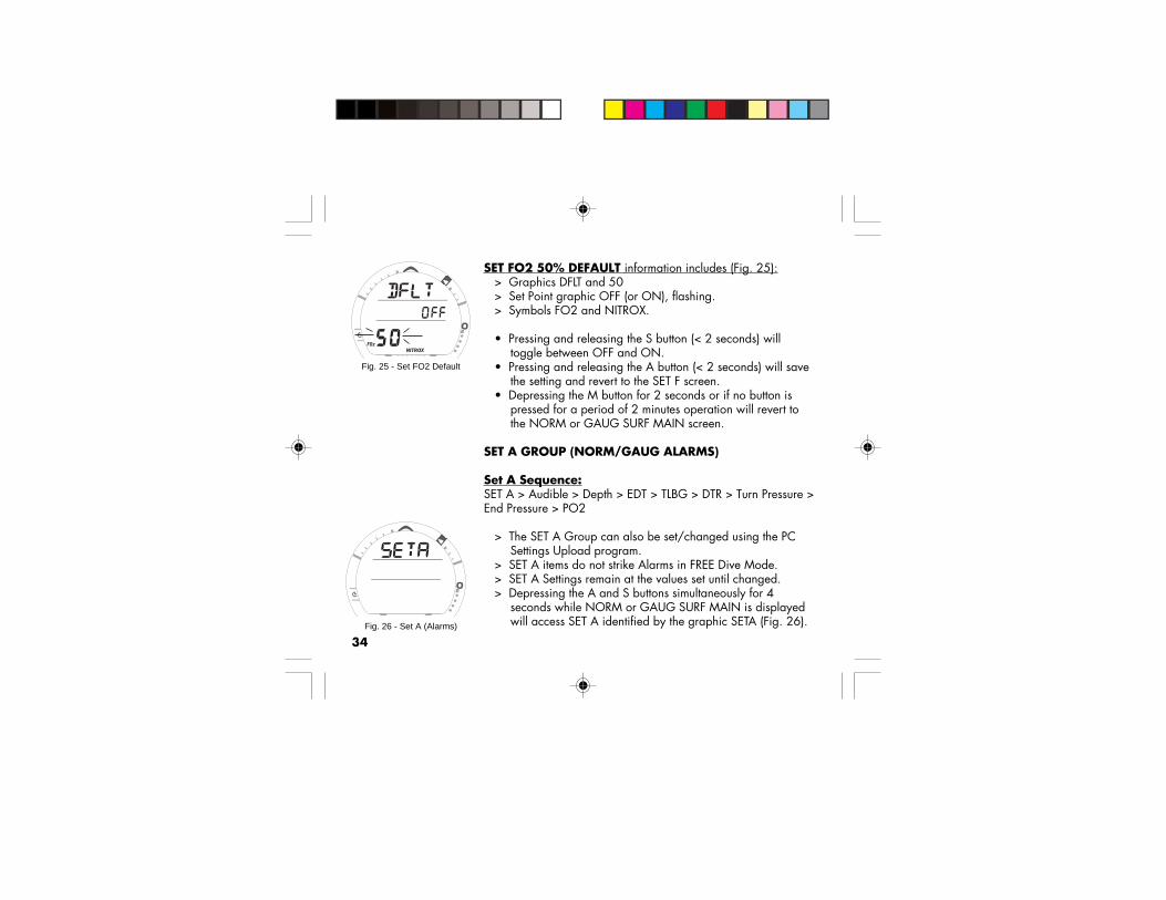
SET FO2 50% DEFAULT information includes (Fig. 25):> Graphics DFLT and 50> Set Point graphic OFF (or ON), flashing.> Symbols FO2 and NITROX.
• Pressing and releasing the S button (< 2 seconds) willtoggle between OFF and ON.
• Pressing and releasing the A button (< 2 seconds) will savethe setting and revert to the SET F screen.
• Depressing the M button for 2 seconds or if no button ispressed for a period of 2 minutes operation will revert tothe NORM or GAUG SURF MAIN screen.
SET A GROUP (NORM/GAUG ALARMS)
Set A Sequence:SET A > Audible > Depth > EDT > TLBG > DTR > Turn Pressure >End Pressure > PO2
> The SET A Group can also be set/changed using the PCSettings Upload program.
> SET A items do not strike Alarms in FREE Dive Mode.> SET A Settings remain at the values set until changed.> Depressing the A and S buttons simultaneously for 4
seconds while NORM or GAUG SURF MAIN is displayedwill access SET A identified by the graphic SETA (Fig. 26).
Fig. 25 - Set FO2 Default
Fig. 26 - Set A (Alarms)

35
> Pressing and releasing the A button momentarily (< 2 seconds) while SET A isdisplayed will advance to SET AUDIBLE ALARM with the Set Point flashing.
SET AUDIBLE ALARMThis option allows the Audible Alarms and the associated red warning LED function to bedisabled.
Some cautionary situations will cause the Audible Alarm to sound and the LED to flasheven if this feature is set to OFF.
SET AUDIBLE ALARM information includes (Fig. 27):> Graphic AUD> Set Point graphic ON (or OFF), flashing.
• Pressing and releasing the S button (< 2 seconds) will toggle between ON and OFF.• Pressing and releasing the A button momentarily (< 2 seconds) will save the setting
and/or advance to the SET DEPTH ALARM screen with the Set Point flashing.• Pressing and releasing the A button repeatedly (< 2 seconds each) will step through
the other SET A screens.• Depressing the A and S buttons simultaneously for 2
seconds will save the setting and revert to the SET A screen.• Depressing the M button for 2 seconds or if no button
action for 2 minutes operation will revert to the NORM orGAUG SURF MAIN screen.
Fig. 27 - Set Audible Alarm

36
SET DEPTH ALARM information includes (Fig. 28):> Graphic DPTH> Symbols MAX and FT (or M)> Set Point graphic value, flashing.
• Pressing and releasing the S button momentarily (< 2seconds) will step through the Set Points from 30 to 330 FT(10 to 100 M) in 10 FT (1 M) increments at a rate of 1 SetPoint per press of the button.
• Depressing and holding the S button will scroll through theSet Points at a rate of 4 Set Points per second until it isreleased.
• Pressing and releasing the A button momentarily (< 2seconds) will save the setting and/or advance to the SETEDT (Elapsed Dive Time) ALARM screen with the Set Pointflashing.
• Pressing and releasing the A button momentarily andrepeatedly (< 2 seconds each time) will step through theother SET A screens.
• Pressing the A and S buttons simultaneously for 2 secondswill save the setting and revert to the SET A screen.
• Depressing and holding the M button for 2 seconds or if nobutton is pressed for a period of 2 minutes operation willrevert to the NORM or GAUG SURF MAIN screen.
FREE Mode has separate Depth Alarms.Fig. 28 - Set Depth Alarm

37
SET EDT (ELAPSED DIVE TIME) ALARMInformation includes (Fig. 29):
> Graphic EDT> Symbols DIVE and TIME.> Set Point value (hr:min), flashing.
• Pressing and releasing the S button momentarily (< 2seconds) will increase the Set Point from 0:10 to 3:00(hours:minutes) in 5 minute (:05) increments.
• Depressing the S button will scroll through the Set Points ata rate of 4 Set Points per second until it is released.
• Pressing and releasing the A button momentarily (< 2seconds) will save the setting and/or advance to the SETTLBG (Tissue Loading Bar Graph) ALARM screen with theSet Point flashing.
• Pressing and releasing the A button repeatedly (< 2seconds each) will step through the other SET A screens.
• Depressing the A and S buttons simultaneously for 2seconds will save the setting and revert to the SET A screen.
• Depressing he M button for 2 seconds or if no button ispressed for 2 minutes operation will revert to the NORM orGAUG SURF MAIN screen.
FREE Mode has a separate EDT Alarm.
Fig. 29 - Set EDT Alarm

38
SET TLBG (TISSUE LOADING BAR GRAPH) ALARMInformation includes (Fig. 30):
> Graphic TLBG> TLBG Set Point (segments), flashing.
• Pressing and releasing the S button momentarily (< 2seconds) will decrease the Set Point from All 8 segments(Deco) to 1 in decrements of 1 segment.
• Depressing the S button will scroll through the Set Points ata rate of 4 Set Points per second until it is released.
• Pressing and releasing the A button momentarily (< 2seconds) will save the setting and/or advance to the SETDTR (Dive Time Remaining) ALARM screen with the SetPoint flashing.
• Pressing and releasing the A button repeatedly (< 2seconds each) will step through the other SET A screens.
• Depressing the A and S buttons simultaneously for 2seconds will save the setting and revert to the SET A screen.
• Depressing the M button for 2 seconds or if no button ispressed for a period of 2 minutes operation will revert tothe NORM or GAUG SURF MAIN screen.
FREE Mode has a separate TLBG Alarm.
Fig. 30 - Set TLBG Alarm
Setting the TLBGAlarm to activatebefore the VT3 entersDECO is highlyrecommended.

39
SET DTR (DIVE TIME REMAINING) ALARMInformation includes (Fig. 31):
> Graphic DTR> Symbols AIR, TIME, NDC, and O2.> Set Point value, flashing.
• Pressing and releasing the S button momentarily (< 2seconds) will increase the Set Point from 0:00 to 0:20(:minutes) in 1 minute (0:01) increments.
• Depressing the S button will scroll through the Set Points ata rate of 4 Set Points per second until it is released.
• Pressing and releasing the A button momentarily (< 2seconds) will save the setting and/or advance to the SETTURN PRESSURE ALARM screen with the Set Point flashing.
• Pressing and releasing the A button momentarily andrepeatedly (< 2 seconds each) will step through the otherSET A screens.
• Depressing the A and S buttons simultaneously for 2seconds will save the setting and revert o the SET A screen.
• Depressing the M button for 2 seconds or if no button ispressed for a period of 2 minutes operation will revert tothe NORM or GAUG SURF MAIN screen.
Fig. 31 - Set DTR Alarm
Whichever Time (NoDecompression, O2,or Air Time Remain-ing) decreases to theAlarm Set Point willactivate the Alarm.
40
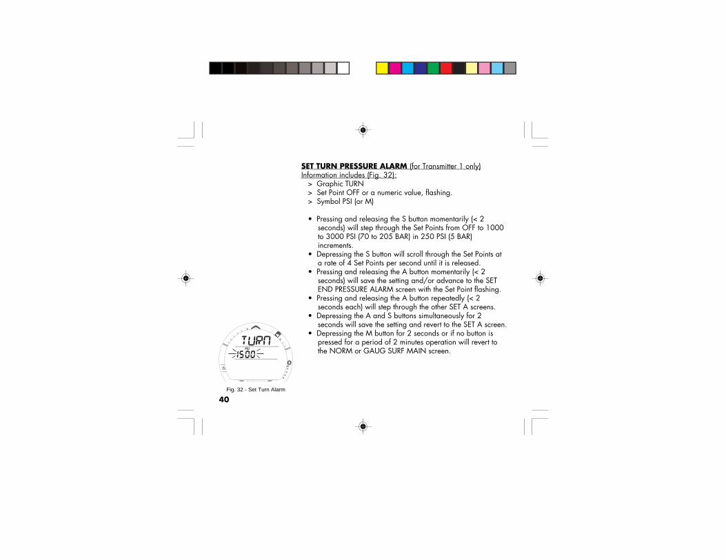
SET TURN PRESSURE ALARM (for Transmitter 1 only)Information includes (Fig. 32):
> Graphic TURN> Set Point OFF or a numeric value, flashing.> Symbol PSI (or M)
• Pressing and releasing the S button momentarily (< 2seconds) will step through the Set Points from OFF to 1000to 3000 PSI (70 to 205 BAR) in 250 PSI (5 BAR)increments.
• Depressing the S button will scroll through the Set Points ata rate of 4 Set Points per second until it is released.
• Pressing and releasing the A button momentarily (< 2seconds) will save the setting and/or advance to the SETEND PRESSURE ALARM screen with the Set Point flashing.
• Pressing and releasing the A button repeatedly (< 2seconds each) will step through the other SET A screens.
• Depressing the A and S buttons simultaneously for 2seconds will save the setting and revert to the SET A screen.
• Depressing the M button for 2 seconds or if no button ispressed for a period of 2 minutes operation will revert tothe NORM or GAUG SURF MAIN screen.
Fig. 32 - Set Turn Alarm

41
SET END PRESSURE ALARM information includes (Fig. 33):> Graphic END> Set Point numeric value, flashing.> Symbol PSI (or M)
• Pressing and releasing the S button momentarily (< 2seconds) will increase the Set Point from 300 to 1500 PSI(20 to 105 BAR) in 100 PSI (5 BAR) increments.
• Depressing the S button will scroll through the Set Points at arate of 4 Set Points per second until it is released.
• Pressing and releasing the A button momentarily (< 2seconds) will save the setting and/or advance to the SETPO2 ALARM screen with the Set Point flashing.
• Pressing and releasing the A button repeatedly (< 2 secondseach) will step through the other SET A screens.
• Depressing the A and S buttons simultaneously for 2 secondswill save the setting and revert to the SET A screen.
• Depressing the M button for 2 seconds or if no button ispressed for a period of 2 minutes operation will revert to theNORM or GAUG SURF MAIN screen.
Fig. 33 - Set End Alarm
The END PRESSUREAlarm will activatewhen Pressure in theTank (TMT 1, 2 , or3) being used at thetime decreases to theAlarm Set Point.

42
SET PO2 ALARM information includes (Fig. 34):> Graphics PO2 and AtA> Set Point value, flashing.> Symbol MAX
• Pressing and releasing the S button momentarily (< 2seconds) will increase the Set Point from 1.20 (ATA) to 1.60(ATA) in .10 (ATA) increments.
• Depressing the S button will scroll through the Set Points ata rate of 4 Set Points per second until it is released.
• Pressing and releasing the A button momentarily (< 2seconds) will save the setting and/or advance to the SET Ascreen.
• Depressing the A and S buttons simultaneously for 2seconds will save the setting and revert to the SET A screen.
• Depressing the M button for 2 seconds or if no button ispressed for a period of 2 minutes operation will revert tothe NORM or GAUG SURF MAIN screen.
Fig. 34 - Set PO2 Alarm
Setting the PO2Alarm to activatebefore reaching theMax allowed limit of1.60 ATA is highlyrecommended.

43
SET U GROUP (UTILITIES)
Set U Sequence:SET U > Wet Activation > Units > Safety Stop > ConservativeFactor > Backlight Duration > Sampling Rate > TMT 1 > TMT 2-3USE > TMT 2 (or BUD 1) > TMT 3 (or BUD 2).
> The SET U Group can also be set/changed using the PCSettings Upload program.
> SET U Settings remain at the values set until changed.> FREE Mode utilizes these settings for Wet Activation, Units,
and Backlight Duration. It has a separate Sampling Ratefixed at a 1 second interval not affected by the SET Usetting.
> Depressing the A and S buttons simultaneously for 6seconds while the NORM or GAUG SURF MAIN screen isdisplayed, will access SET U identified by the graphic SETU(Fig. 35).
> Pressing and releasing the A button momentarily (< 2seconds) while SET U is displayed will advance to SET WETACTIVATION with the Set Point flashing.
Fig. 35 - SET U (Utilities)
TMT is the abbreviationused for Transmitter.
BUD is the abbreviationused for Buddy.

44
SET WET ACTIVATION information includes (Fig. 36):> Graphic WET> Set Point graphic ON (or OFF) flashing.
• Pressing and releasing the S button will toggle between ONand OFF.
• Pressing and releasing the A button momentarily (< 2seconds) will save the setting and/or advance to the SETUNITS screen with the Set Point flashing.
• Pressing and releasing the A button repeatedly (< 2seconds each) will step through the other SET U screens.
• Depressing the A and S buttons simultaneously for 2seconds will save the setting and revert to the SET U screen.
• Depressing the M button for 2 seconds or if no button ispressed for a period of 2 minutes operation will revert tothe NORM or GAUG SURF MAIN screen.
HINT: To change this setting while operating inFREE Mode, first access the NORM SURF Mode.
Fig. 36 - Set Wet Activation

45
SET UNITS information includes (Fig. 37):> Graphic UNIT> Set Point symbols/graphics PSI, F, and FT (or BAR, C, and
M), flashing.
• Pressing and releasing the S button will toggle betweenImperial (F, FT, PSI) and Metric (C, M, BAR).
• Pressing and releasing the A button momentarily (< 2seconds) will save the setting and/or advance to the SETSAFETY STOP screen with the Time Set Point flashing.
• Pressing and releasing the A button repeatedly (< 2seconds each) will step through the other SET U screens.
• Depressing the A and S buttons simultaneously for 2seconds will save the setting and revert to the SET U screen.
• Depressing the M button for 2 seconds or if no button ispressed for a period of 2 minutes operation will revert tothe NORM or GAUG SURF MAIN screen.
HINT: To change this setting while operating inFREE Mode, first access the NORM SURF Mode.
Fig. 37 - Set Units

46
SET NORM SAFETY STOP information includes (Fig. 38):> Graphic SAFE> Symbols STOP and TIME.> Safety Stop Time Set Point, flashing.> Safety Stop Depth Set Point and symbol FT (or M).
• Pressing and releasing the S button momentarily (< 2 seconds each) will step throughthe Stop Time Set Points of OFF, 3:00, and 5:00 (minutes:seconds).
• Pressing and releasing the A button momentarily (< 2 seconds) will save the Stop Timesetting and the Stop Depth Set Point will flash, or if Stop Time is set OFF advance tothe SET CONS (Conservative Factor) screen with the Set Point flashing.
• Pressing and releasing the S button momentarily (< 2 seconds each) will step throughthe Stop Depth Set Points of 10, 15, and 20 FT (or 3, 4, 5, and 6 M).
• Pressing and releasing the A button momentarily (< 2 seconds) will save the SafetyStop settings and/or advance to the SET CONS screen with the Set Point flashing.
• Pressing the A button repeatedly (< 2 seconds) will step through the other SET Uscreens.
• Depressing the A and S buttons simultaneously for 2 secondswill save the settings and revert to the SET U screen.• Depressing the M button for 2 seconds or if no button ispressed for a period of 2 minutes operation will revert to theNORM or GAUG SURF MAIN screen.
Fig. 38 - Set Safety Stop

47
SET CONSERVATIVE FACTOR information includes (Fig. 39):> Graphic CONS> Set Point ON (or OFF), flashing.> Symbols TIME and NDC.
• Pressing and releasing the S button (< 2 seconds) willtoggle between ON and OFF.
• Pressing and releasing the A button momentarily (< 2seconds) will save the setting and/or advance to the SETBACKLIGHT DURATION screen with the Set Point flashing.
• Pressing and releasing the A button repeatedly (< 2seconds each) will step through the other SET U screens.
• Depressing the A and S buttons simultaneously for 2seconds will save the setting and revert to the SET U screen.
• Depressing the M button for 2 seconds or if no button ispressed for a period of 2 minutes operation will revert tothe NORM or GAUG SURF MAIN screen.
NOTE: When the Conservative Factor is set ON,the No Decompression Limit dive times are re-duced to values equivalent to those that wouldbe available at the next higher 3000 foot (915meter) Altitude. Refer to the tables on Pages150/151.
Fig. 39 - Set ConservativeFactor

48
SET BACKLIGHT DURATION information includes (Fig. 40):> Graphic GLO.> Symbol TIME.> Set Point, flashing.
• Pressing and releasing the S button momentarily (< 2seconds each) will step through the Set Points of :00, :05,and :10 (seconds).
• Pressing and releasing the A button momentarily (< 2seconds) will save the setting and/or advance to the SETSAMPLING RATE screen with the Set Point flashing.
• Pressing and releasing the A button repeatedly (< 2seconds each) will step through the SET U screens.
• Depressing the A and S buttons simultaneously for 2seconds will save the setting and revert to the SET U screen.
• Depressing the M button for 2 seconds or if no button ispressed for a period of 2 minutes operation will revert to theNORM or GAUG SURF MAIN screen.
HINT: To change the Backlight Duration whileoperating in FREE Mode, first access the NORMSURF Mode.
Fig. 40 - Set BacklightDuration

49
SET SAMPLING RATE information includes (Fig. 41):> Graphic SAMP> Symbol TIME.> Set Point, flashing.
• Pressing and releasing the S button momentarily (< 2seconds) will step through the Set Points of :02, :15, :30,:60 (seconds).
• Depressing the S button will scroll through the Set Points ata rate of 4 Set Points per second until it is released.
• Pressing and releasing the A button momentarily (< 2seconds) will save the setting and/or advance to the SETTMT 1 screen with the Set Point flashing.
• Pressing and releasing the A button repeatedly (< 2seconds each) will step through the other SET U screens.
• Depressing the A and S buttons simultaneously for 2seconds shall save the setting and revert to the SET Uscreen.
• Depressing the M button for 2 seconds or if no button ispressed for a period of 2 minutes operation will revert tothe NORM or GAUG SURF MAIN screen.
NOTE: FREE Mode has a separate fixed Sam-pling Rate of 1 second.
Fig. 41 - Set Sampling Rate
SAMPLING RATE isthe frequency (timeinterval) at whichdata is sampled andstored in memory forsubsequent down-load to the PCOceanLog program.
50
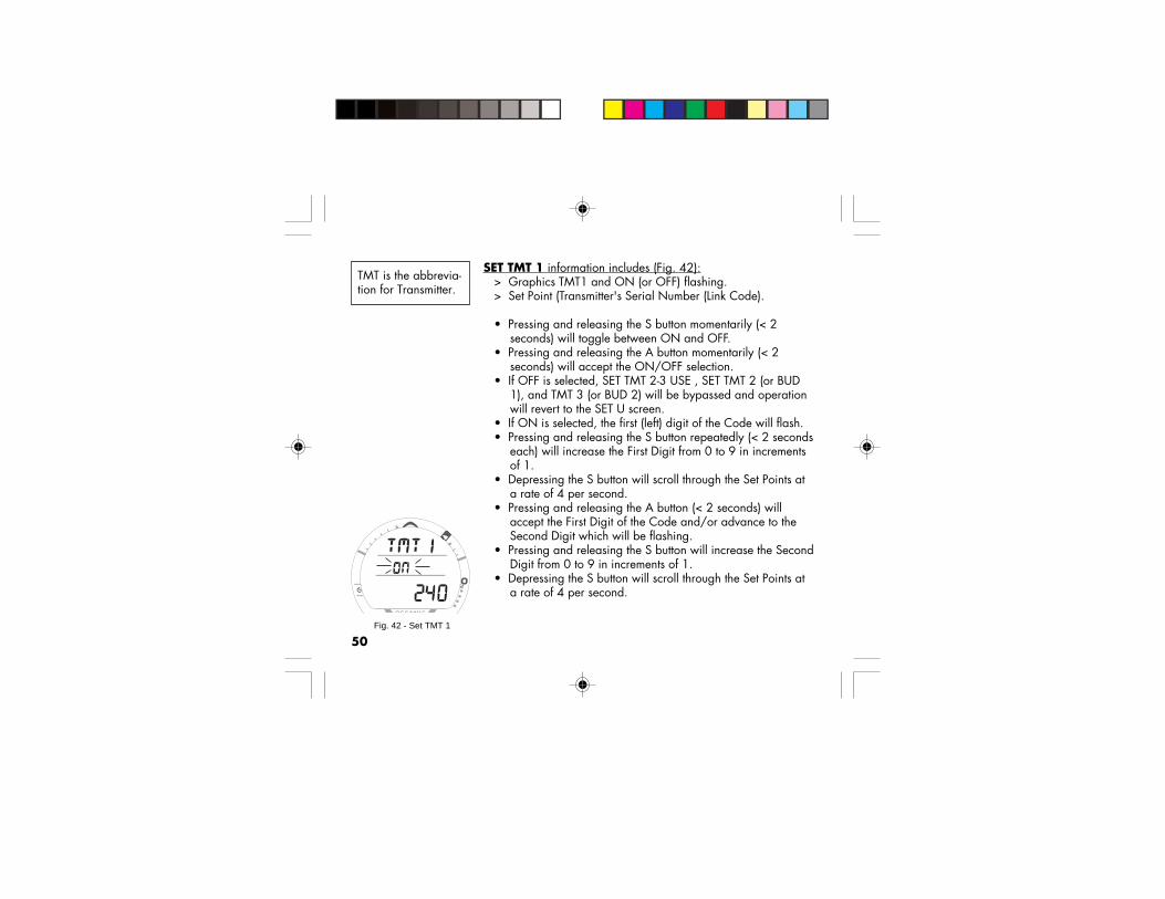
SET TMT 1 information includes (Fig. 42):> Graphics TMT1 and ON (or OFF) flashing.> Set Point (Transmitter's Serial Number (Link Code).
• Pressing and releasing the S button momentarily (< 2seconds) will toggle between ON and OFF.
• Pressing and releasing the A button momentarily (< 2seconds) will accept the ON/OFF selection.
• If OFF is selected, SET TMT 2-3 USE , SET TMT 2 (or BUD1), and TMT 3 (or BUD 2) will be bypassed and operationwill revert to the SET U screen.
• If ON is selected, the first (left) digit of the Code will flash.• Pressing and releasing the S button repeatedly (< 2 seconds
each) will increase the First Digit from 0 to 9 in incrementsof 1.
• Depressing the S button will scroll through the Set Points ata rate of 4 per second.
• Pressing and releasing the A button (< 2 seconds) willaccept the First Digit of the Code and/or advance to theSecond Digit which will be flashing.
• Pressing and releasing the S button will increase the SecondDigit from 0 to 9 in increments of 1.
• Depressing the S button will scroll through the Set Points ata rate of 4 per second.
Fig. 42 - Set TMT 1
TMT is the abbrevia-tion for Transmitter.

51
• Pressing and releasing the A button (< 2 seconds) will accept the Second Digit of theCode and/or advance to the Third Digit which will be flashing.
• Pressing and releasing the S button repeatedly (< 2 seconds each) will increase theThird Digit from 0 to 9 in increments of 1.
• Depressing the S button will scroll through the Set Points at a rate of 4 per second.• Pressing and releasing the A button (< 2 seconds) will accept the Third Digit of the
Code and/or advance to the Fourth Digit which will be flashing.• Pressing and releasing the S button repeatedly (< 2 seconds each) will increase the
Fourth Digit from 0 to 9 in increments of 1.• Depressing the S button will scroll through the Set Points at a rate of 4 per second.• Pressing and releasing the A button (< 2 seconds) will accept the Fourth Digit of the
Code and/or advance to the Fifth Digit which will be flashing.• Pressing and releasing the S button repeatedly (< 2 seconds each) will increase the
Fifth Digit from 0 to 9 in increments of 1.• Depressing the S button will scroll through the Set Points at a rate of 4 per second.• Pressing and releasing the A button will accept the Fifth Digit of the Code and/or
advance to the Sixth Digit which will be flashing.• Pressing and releasing the S button repeatedly (< 2 seconds each) will increase the
Sixth Digit from 0 to 9 in increments of 1.• Depressing the S button will scroll through the Set Points at a rate of 4 per second.• Pressing and releasing the A button (< 2 seconds) will accept the TMT 1 Link Code
and/or advance to SET TMT 2-3 USE with the Set Point flashing.• Depressing the A and S buttons simultaneously for 2 seconds will save the setting and
revert back to the SET U screen.

52
SET TMT 2-3 USE information includes (Fig. 43):> Graphics TMT and 2-3 USE.> Set Point graphic SELF (or bud) flashing.
• Pressing and releasing the S button momentarily (< 2seconds) will toggle between SELF and bud.
• Pressing and releasing the A button momentarily (< 2seconds) will accept the setting and/or advance to SETTMT 2 (or BUD 1) with ON or OFF flashing.
• Depressing the A and S buttons simultaneously for 2seconds will save the setting and revert to the SET Uscreen.
• Depressing the M button for 2 seconds or if no button ispressed for a period of 2 minutes operation will revert tothe NORM or GAUG SURF MAIN screen.
When set for SELF, TMT 2 and TMT 3 are associated withTransmitters to be used by the diver using the VT3 for GasSwitching.
When set for BUD, TMT 1 is associated with the user of the VT3and TMT 2 and TMT 3 are associated with Transmitters to beused by other divers (Buddies) whose Pressure can be checkedby the user of the VT3.
Fig. 43 - Set TMT 2-3 Use

53
SET TMT 2 (or BUD 1) information includes (Fig. 44):> Graphics TMT2 (or BUD1) and ON (or OFF) flashing.> Set Point (Transmitter's Serial Number (Link Code).
• Pressing and releasing the S button momentarily (< 2seconds) will toggle between ON and OFF.
• Pressing and releasing the A button momentarily (< 2seconds) will accept the ON/OFF selection.
• If OFF is selected, SET TMT 3 (or BUD 2) will be bypassedand the operation will revert to the SET U screen.
• If ON is selected, the first (left) digit of the Code will flash.• Pressing and releasing the S button repeatedly (< 2 seconds
each) will increase the First Digit from 0 to 9 in incrementsof 1.
• Depressing the S button will scroll through the Set Points ata rate of 4 per second.
• Pressing and releasing the A button (< 2 seconds) willaccept the First Digit of the Code and/or advance to theSecond Digit which will be flashing.
• Pressing and releasing the S button will increase the SecondDigit from 0 to 9 in increments of 1.
• Depressing the S button will scroll through the Set Points ata rate of 4 per second.
• Pressing and releasing the A button (< 2 seconds) willaccept the Second Digit of the Code and/or advance to theThird Digit which will be flashing. Fig. 44 - Set TMT 2 or BUD 1
If TMT 2-3 USE is set forSELF (Gas Switching)
If TMT 2-3 USE is set forBuddy Pressure Check
- OR -

54
• Pressing and releasing the S button repeatedly (< 2 seconds each) will increase theThird Digit from 0 to 9 in increments of 1.
• Depressing the S button will scroll through the Set Points at a rate of 4 per second.• Pressing and releasing the A button (< 2 seconds) will accept the Third Digit of the
Code and/or advance to the Fourth Digit which will be flashing.• Pressing and releasing the S button repeatedly (< 2 seconds each) will increase the
Fourth Digit from 0 to 9 in increments of 1.• Depressing the S button will scroll through the Set Points at a rate of 4 per second.• Pressing and releasing the A button (< 2 seconds) will accept the Fourth Digit of the
Code and/or advance to the Fifth Digit which will be flashing.• Pressing and releasing the S button repeatedly (< 2 seconds each) will increase the
Fifth Digit from 0 to 9 in increments of 1.• Depressing the S button will scroll through the Set Points at a rate of 4 per second.• Pressing and releasing the A button will accept the Fifth Digit of the Code and/or
advance to the Sixth Digit which will be flashing.• Pressing and releasing the S button repeatedly (< 2 seconds each) will increase the
Sixth Digit from 0 to 9 in increments of 1.• Depressing the S button will scroll through the Set Points at a rate of 4 per second.• Pressing and releasing the A button (< 2 seconds) will accept the TMT 2 (or BUD 1)
Link Code and/or advance to SET TMT 3 (or BUD 2) with ON or OFF flashing.• Depressing the A and S buttons simultaneously for 2 seconds will save the setting and
revert to the SET U screen.

55
SET TMT 3 (or BUD 2) information includes (Fig. 45):> Graphics TMT3 (or BUD2), and ON (or OFF) flashing.> Set Point (Transmitter's Serial Number (Link Code)).
• Pressing and releasing the S button momentarily (< 2seconds) will toggle between ON and OFF.
• Pressing and releasing the A button momentarily (< 2seconds) will accept the ON/OFF selection.
• If OFF is selected, operation reverts to the SET U screen.• If ON is selected, the first (left) digit of the Code will flash.• Pressing and releasing the S button repeatedly (< 2 seconds
each time) will increase the First Digit from 0 to 9 inincrements of 1.
• Depressing the S button will scroll through the Set Points ata rate of 4 per second.
• Pressing and releasing the A button (< 2 seconds) willaccept the First Digit of the Code and/or advance to theSecond Digit which will be flashing.
• Pressing and releasing the S button will increase the SecondDigit from 0 to 9 in increments of 1.
• Depressing the S button will scroll through the Set Points ata rate of 4 per second.
• Pressing and releasing the A button (< 2 seconds) willaccept the Second Digit of the Code and/or advance to theThird Digit which will be flashing.
Fig. 45 - Set TMT 3
If TMT 2-3 USE is set forSELF (Gas Switching)
If TMT 2-3 USE is set forBuddy Pressure Check
- OR -

56
• Pressing and releasing the S button repeatedly (< 2 seconds each) will increase theThird Digit from 0 to 9 in increments of 1.
• Depressing the S button will scroll through the Set Points at a rate of 4 per second.• Pressing and releasing the A button (< 2 seconds) will accept the Third Digit of the
Code and/or advance to the Fourth Digit which will be flashing.• Pressing and releasing the S button repeatedly (< 2 seconds each) will increase the
Fourth Digit from 0 to 9 in increments of 1.• Depressing the S button will scroll through the Set Points at a rate of 4 per second.• Pressing and releasing the A button (< 2 seconds) will accept the Fourth Digit of the
Code and/or advance to the Fifth Digit which will be flashing.• Pressing and releasing the S button repeatedly (< 2 seconds each) will increase the
Fifth Digit from 0 to 9 in increments of 1.• Depressing the S button will scroll through the Set Points at a rate of 4 per second.• Pressing and releasing the A button will accept the Fifth Digit of the Code and/or
advance to the Sixth Digit which will be flashing.• Pressing and releasing the S button repeatedly (< 2 seconds each) will increase the
Sixth Digit from 0 to 9 in increments of 1.• Depressing the S button will scroll through the Set Points at a rate of 4 per second.• Pressing and releasing the A button (< 2 seconds) will accept TMT 3 (or BUD 2) Link
Code and/or advance to the SET U screen.

57
SET T GROUP (TIME/DATE)
Set T Sequence:SET T > Hour Format > Hour > Minute > Year > Month > Day
> The SET T Group can also be set/changed using the PCSettings Upload program.
> SET T Settings remain at the values set until changed.> FREE Mode utilizes these settings.> Day of the Week is set automatically when the Date is set.
• Depressing the A and S buttons simultaneously for 8seconds while the NORM or GAUG SURF MAIN screen isdisplayed, will access SET T identified by the graphic SETT(Fig. 46).
• Depressing the M button at any time for 2 seconds and if nobutton is pressed during a period of 2 minutes, the unit willrevert to the NORM or GAUG SURF MAIN screen.
• Pressing and releasing the A button momentarily (< 2seconds) while SET T is displayed will advance to SETHOUR FORMAT with the Set Point flashing.
Fig. 46 - Set T
The YEAR will not bedisplayed in anyMode other thanSET DATE. TheDATE will reset to1.1 2006 when theBattery is replaced.
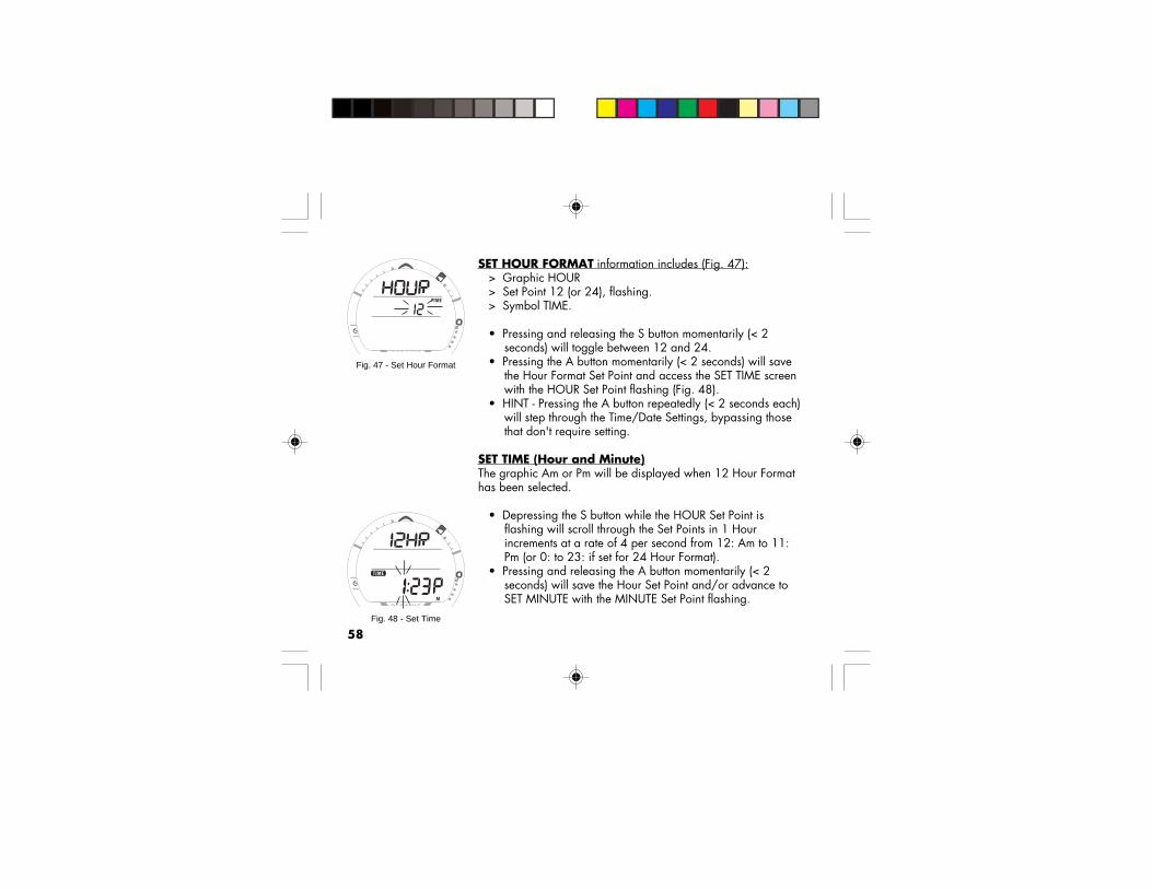
58
SET HOUR FORMAT information includes (Fig. 47):> Graphic HOUR> Set Point 12 (or 24), flashing.> Symbol TIME.
• Pressing and releasing the S button momentarily (< 2seconds) will toggle between 12 and 24.
• Pressing the A button momentarily (< 2 seconds) will savethe Hour Format Set Point and access the SET TIME screenwith the HOUR Set Point flashing (Fig. 48).
• HINT - Pressing the A button repeatedly (< 2 seconds each)will step through the Time/Date Settings, bypassing thosethat don't require setting.
SET TIME (Hour and Minute)The graphic Am or Pm will be displayed when 12 Hour Formathas been selected.
• Depressing the S button while the HOUR Set Point isflashing will scroll through the Set Points in 1 Hourincrements at a rate of 4 per second from 12: Am to 11:Pm (or 0: to 23: if set for 24 Hour Format).
• Pressing and releasing the A button momentarily (< 2seconds) will save the Hour Set Point and/or advance toSET MINUTE with the MINUTE Set Point flashing.
Fig. 47 - Set Hour Format
Fig. 48 - Set Time

59
• Depressing the S button while the MINUTE Set Point is flashing will scroll through theSet Points in 1 minute increments at a rate of 4 per second from :00 to :59.
• Pressing and releasing the A button momentarily (< 2 seconds) will save the MinuteSet Point and/or advance to the SET DATE screen.
SET DATE (Year, Month, and Day)Displayed will be the graphic YEAR, Month and Day (or Day and Month if set for metric)with the YEAR Set Point flashing (Fig. 49).
• Depressing the S button will scroll through the YEAR Set Points in 1 year increments ata rate of 4 per second from 2006 to 2049 (with leap year corrections).
• Pressing and releasing the A button momentarily (< 2 sec) will save the Year Set Pointand/or advance to SET MONTH with the Set Point flashing and the graphic MNTHreplacing the graphic YEAR.
• Depressing the S button will scroll through the MONTH Set Points in 1 monthincrements at a rate of 4 per second from 1 to 12.
• Pressing and releasing the A button momentarily (< 2 seconds) will save the MonthSet Point and/or advance to SET DAY with the Set Pointflashing and the graphic DAY (replacing the graphicMNTH.
• Depressing the S button will scroll through the DAY SetPoints in one day (01) increments at a rate of 4 per secondfrom 1 to 31.
• Pressing and releasing the A button momentarily (< 2seconds) will save the Set Point and/or advance to the SE Tscreen. Fig. 49 - Set Date

60
SERIAL NUMBER (VT3)• Depressing the A and S buttons simultaneously for 10
seconds while viewing the NORM or GAUG SURF MAINscreen will access the VT3's SERIAL NUMBER screendisplaying (Fig. 50):
> Graphic SN> Factory programmed Serial Number of the VT3.> Firmware revision number (e.g., graphic r1A).
• Depressing the A and S buttons simultaneously for 2seconds will revert to the SURF MAIN screen.
• Depressing the M button for 2 seconds will revert to theSURF MAIN screen.
• If no button is pressed during a period of 2 minutes, the unitwill revert to the SURF MAIN screen.
NOTE: The Serial Number and Firmware Revi-sion will be requested in the event that youcontact Oceanic regarding your VT3. Enter themin the Records section provided in the back ofthis Manual.
Fig. 50 - SERIAL NUMBER(of the VT3)

61
NORM SURF ALT, information includes (Fig. 51):> Day of the Week graphic (SAT, SUN, MON, TUE, WED,
THU, FRI).> Temperature with degree icon and graphic F (or C)> Time of Day (hour:minute).
• Pressing and releasing the A button momentarily (< 2seconds) will access the NORM PLAN Lead-in screen.
• Pressing the S button will activate the Backlight.• The display will revert to the NORM SURF MAIN screen if
the M button is pressed for 2 seconds or after 5 secondswith no M or A button action.
NORM PLAN MODE
Oceanic strongly recommends that you review thePre Dive Planning Sequence (PDPS) prior to everyNORM dive to help you Plan your dive as required toavoid exceeding no decompression or oxygen expo-sure limits. This is especially important for repetitive diveswhen the PDPS indicates adjusted dive times that are availablefor the next dive, based on residual nitrogen or oxygen accumu-lation (whichever is in control) following the last dive and surfaceinterval.
Fig. 51 - NORM SURF ALT

62
NOTE: No Decompression Dive Times in NORMPLAN MODE are based on the FO2 setting forGAS 1. The FO2 settings for GAS2 and GAS3are not utilized for Plan calculations.
• Pressing and releasing the A button momentarily (< 2seconds) 1 time while the NORM SURF MAIN screen isdisplayed will access the PLAN MODE Lead-in screen(NORM SURF > PLAN Lead-in).
• While in the PLAN MODE, pressing and releasing the Sbutton repeatedly (< 2 seconds each time) will increase thePlanned Depth in increments of 10 FT (3 M), displaying theinformation one screen at a time.
Information provided includes Depths and allowable No Decom-pression Dive Times. The screens will sequence through Depthsfrom 30 to 190 FT (9 to 57 M), or the Maximum Depth that willallow theoretical No Decompression Dive Time of at least 1minute based upon the previous dive profiles in a series ofrepetitive dives and taking into account descent and ascent ratesof 60 FPM (18 MPM).
NOTE: When the Conservative Factor is set ON,No Decompression Dive times are reduced to thevalues of the next 3000 foot (915 meter) higherAltitude.
NDLs, AIR Dive at SeaLevel (no dive made yet)
DEPTH NDLFT (M) HR:MIN30 (9) 4:20 (4:43)40 (12) 2:17 (2:24)50 (15) 1:21 (1:25)60 (18) :57 (:59)70 (21) :40 (:41)80 (24) :30 (:32)90 (27) :24 (:25)100 (30) :19 (:20)110 (33) :16 (:17)120 (36) :13 (:14)130 (39) :11 (:11)140 (42) :09 (:09)150 (45) :08 (:08)160 (48) :07 (:07)170 (51) :07 (:06)180 (54) :06 (:06)190 (57) :05 (:05)
Refer to the charts onpages 150 and 151for complete listings ofNo DecompressionLimits for Sea Level andAltitudes up to 14,000feet (4,270 meters).

63
If FO2 for GAS1 is set for a numerical value (21 to 50%), the NITROX graphic and Maxi-mum Operating Depth defined by the PO2 ALARM Set Point will be displayed.
If the limiting time factor is Oxygen controlled, the symbols TIME and O2 will be dis-played. If the limiting time factor is Nitrogen controlled, the symbols TIME and NDC willbe displayed.
• Prior to a first dive of a series, pressing and releasing the Abutton momentarily (< 2 seconds) will advance to LOGMODE.
• After a dive is made, it will advance to FLY MODE.• Depressing the M button for 2 seconds, or if no button is
pressed during a 2 minute period, operation will revert tothe NORM SURF MAIN screen.
PLAN MODE LEAD-IN information includes (Fig. 52A/B):> Graphic PLAN.> PO2 Alarm Set Point and graphic PO2, if set for Nitrox.> FO2 icon and FO2 Set Point for GAS 1.> Tank 1 icon representing GAS 1.> Symbol NITROX, if set for Nitrox.
• Press and release the S button momentarily (< 2 seconds) toaccess the first screen (30 FT/9 M) of the Pre Dive PlanningSequence (PDPS). Fig. 52B - PLAN LEAD-IN
(FO2 set for 32%)
Fig. 52A - PLAN LEAD-IN(FO2 set for AIR)
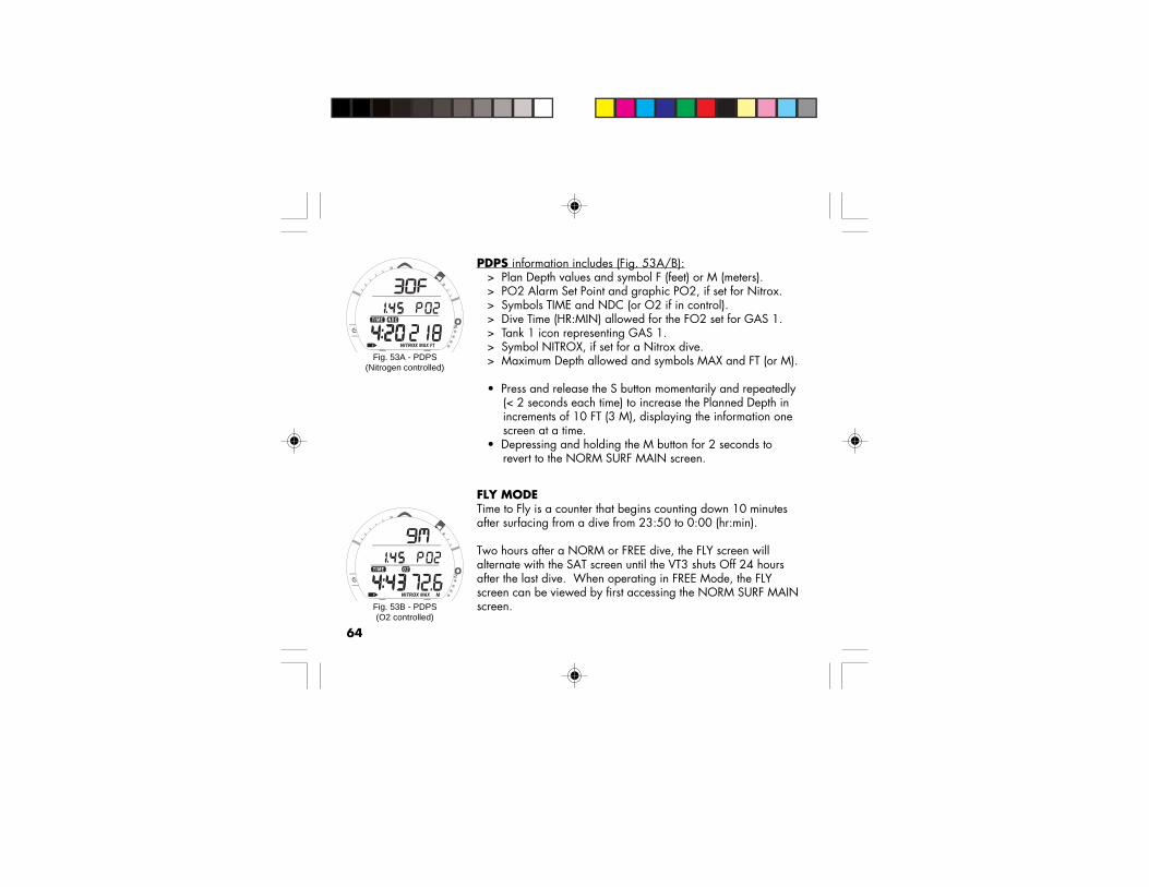
64
PDPS information includes (Fig. 53A/B):> Plan Depth values and symbol F (feet) or M (meters).> PO2 Alarm Set Point and graphic PO2, if set for Nitrox.> Symbols TIME and NDC (or O2 if in control).> Dive Time (HR:MIN) allowed for the FO2 set for GAS 1.> Tank 1 icon representing GAS 1.> Symbol NITROX, if set for a Nitrox dive.> Maximum Depth allowed and symbols MAX and FT (or M).
• Press and release the S button momentarily and repeatedly(< 2 seconds each time) to increase the Planned Depth inincrements of 10 FT (3 M), displaying the information onescreen at a time.
• Depressing and holding the M button for 2 seconds torevert to the NORM SURF MAIN screen.
FLY MODETime to Fly is a counter that begins counting down 10 minutesafter surfacing from a dive from 23:50 to 0:00 (hr:min).
Two hours after a NORM or FREE dive, the FLY screen willalternate with the SAT screen until the VT3 shuts Off 24 hoursafter the last dive. When operating in FREE Mode, the FLYscreen can be viewed by first accessing the NORM SURF MAINscreen.
Fig. 53A - PDPS(Nitrogen controlled)
Fig. 53B - PDPS(O2 controlled)

65
During the first 2 hours after a dive -• pressing and releasing the A button 3 times momentarily (<
2 seconds each time) while the NORM SURF MAIN screenis displayed will access FLY MODE (NORM SURF MAIN >ALT > PLAN > FLY, or -
• pressing and releasing the A button 2 times momentarily (<2 seconds each) while the GAUG SURF MAIN screen isdisplayed will access FLY MODE (GAUG SURF MAIN >ALT > FLY).
TIME TO FLY information includes (Fig. 54):> Graphic FLY and symbol TIME.> Countdown Time (hr:min).> Battery icon if a VT3 Low Battery Warning Condition exists,
flashing if Too Low
• Pressing and releasing the A button momentarily (< 2seconds) will advance to SAT MODE.
• Depressing the M button for 2 seconds will revert to theNORM or GAUG SURF MAIN screen.
• If no button is pressed during a 2 minute period, operationwill revert to the NORM or GAUG SURF MAIN screen.
• Pressing the S button will activate the Backlight.
Fig. 54 - Time to Fly

66
SAT MODEThe Time to Desaturate counter provides calculated time for Tissue Desatuation at sea leveltaking into consideration the Conservation Factor setting. It begins counting down 10minutes after surfacing from a dive, counting down from 23:50 max to 0:00 (hr:min).
When the Countdown reaches 0:00, which will generally occur prior to the FLY count-down reaching 0:00, the SAT screen continues to alternate with FLY displaying 0:00 untilthe FLY counter shuts the VT3 Off 24 hours after a last dive.
> The SAT screen is not displayed after a Violation Dive.> Desaturation requiring Times greater than 24 hours will display 23: - - .> In the event that Time to Desaturate still remains at the end of 24 hours, the added
time will be zeroed.
During the first 2 hours after a dive -• pressing and releasing the A button 4 times momentarily (< 2 seconds each time)
while the NORM SURF MAIN screen is displayed will access SAT MODE (NORMSURF MAIN > ALT > PLAN > FLY > SAT, or -
• the SAT screen is not accessible from GAUG SURF MAIN.
Two hours after a NORM or FREE dive, the SAT screen will alternate with the FLY screenuntil the VT3 shuts Off 24 hours after the last dive. When operating in FREE Mode, theSAT screen can be viewed by first accessing the NORM SURF MAIN screen.

67
TIME TO DESAT information includes (Fig. 55):> Graphic SAT and symbol TIME.> Countdown Time (hr:min).> Battery icon (if an VT3 Low Battery Warning Condition
exists), flashing if Too Low
• Pressing and releasing the A button momentarily (< 2seconds) will advance to LOG MODE.
• Depressing the M button for 2 seconds will revert to theNORM or GAUG SURF MAIN screen.
• If no button is pressed during a 2 minute period, the unitwill revert to the NORM or GAUG SURF MAIN screen.
• Pressing the S button will activate the Backlight.
NORM/GAUG LOG MODELOG MODE displays information from the latest 24 NORM/GAUG dives sequentially in reverse order (the most recent first).
LOG information is retained until deleted by another dive.> After exceeding 24 dives, the most recent Dive completed
will be added to the LOG and the oldest deleted.
Battery removal will not affect the LOG data stored for viewing.
Fig. 55 - Time to Desat

68
Dives will be numbered 1 to 24 starting at #1 each time a new series of dives begins.After it shuts Off 24 hours after a dive, the first dive of the next new series will be #1.
Accessing LOG Mode:• During the first 10 minutes after a dive, pressing and releasing the A button
momentarily (< 2 seconds) 1 time while the NORM or GAUG SURF MAIN screen isdisplayed will access LOG MODE. (NORM or GAUG SURF MAIN > LOG)
• 10 minutes after a Non Violation Dive, pressing and releasing the A button 5 times (<2 seconds each time) while the NORM SURF MAIN screen is displayed will accessthe LOG MODE (NORM SURF MAIN > PLAN > FLY > SAT > LOG), or -
> pressing and releasing the A button 2 times (< 2 seconds each time) while the GAUGSURF MAIN screen is displayed will access the LOG MODE (GAUG SURF MAIN >FLY > LOG).
• 10 minutes after a Violation Dive, pressing and releasing the A button 23 times (< 2seconds each time) while the NORM or GAUG SURF MAIN screen is displayed willaccess the LOG MODE (NORM or GAUG SURF MAIN > FLY LOG). PLAN and SATscreens will not be available after a Violation Dive.
Upon accessing LOG MODE, the most recent NORM or GAUG dive’s LOG PREVIEWscreen will be displayed.
• Depressing the S button for 2 seconds will display the previous dive’s PREVIEWscreen. Subsequent presses of S will step through other previous dives' PREVIEWscreens.

69
• Pressing and releasing the S button momentarily (< 2 seconds) while viewing aPREVIEW screen will display that dive’s LOG DATA 1 screen (Nitrogen Data).
• If that was a Nitrox dive, pressing and releasing the S button again will display thatdive’s LOG DATA 2 screen (Oxygen Data). If in GAUGE MODE (Violated or UserSelected), this screen will not be displayed.
• LOG screens remain on display until further button action occurs.
• Once the S button is pressed, pressing and releasing the A button momentarily (< 2seconds) button will revert to NORM or GAUG SURF MAIN screen.
• Depressing and holding the M button for 2 seconds or if no button is pressed during a2 minute period operation will revert to the NORM or GAUG SURF MAIN screen.
• Pressing the S button will activate the Backlight.
LOG PREVIEW screen information includes (Fig. 56):> Graphic LOG.> Date (month.day, or day.month if set for metric).> Symbol DIVE and dive number (1 to 24) for that series.> Time of Day the dive began (hr:min) with graphic Am/Pm if
set for 12 Hour Format.> Symbol NITROX if a Nitrox dive, none if a NORM AIR, or
GAUG dive.
• Pressing and releasing the S button momentarily (< 2seconds) button will advance to the LOG DATA 1 screen.
• Pressing and holding the S button will scroll through theprevious Log Preview screens. Fig. 56 - LOG PREVIEW

70Fig. 57 - LOG DATA 1
LOG DATA 1 information includes (Fig. 57):> Alpha graphic NO-D, DECO, GAUG, or VIOL.> TLBG with the maximum accumulation segment flashing,
others fixed up to end-of-dive accumulation. All segmentsflashing for delayed and full violation.
> VARI - showing the maximum ascent rate maintained for 4consecutive seconds during the dive.
> Temperature (minimum recorded that dive) and graphic F(or C).
> Symbols DIVE and TIME and Elapsed Dive Time (hr:min).> Symbols TIME and SURFACE.> Pre-dive Surface Interval (hr:min), 10 - through 23 - for times
greater than 9:59 (hr:min), blank for Dive 1 of a series.> Maximum Depth and symbols MAX and FT (or M).> Symbol NITROX, if a NORM Nitrox dive, none if a NORM
AIR or GAUG dive.
• Pressing and releasing the S button momentarily (< 2seconds) button will advance to the LOG DATA 2 screen.
• Depressing the M button for 2 seconds or if no button ispressed during a 2 minute period operation will revert tothe NORM or GAUG SURF MAIN screen.
• Pressing the S button will activate the Backlight.

71
Fig. 58 - LOG DATA 2
LOG DATA 2 (if a Nitrox dive) information includes (Fig. 58):> Graphic O2.> O2 bar graph segments representing Oxygen accumulated
at the end of the dive.> Value of Max PO2 achieved (ATA) and graphic PO2.> GAS 1 FO2 Set Point for that dive and symbol FO2.> Tank 1 icon representing GAS 1.> Symbol NITROX.
• Pressing and releasing the S button momentarily (< 2seconds) button will advance to the previous dive's LOGPREVIEW screen.
• Depressing the M button for 2 seconds or if no button ispressed during a 2 minute period operation will revert tothe NORM or GAUG SURF MAIN screen.
• Pressing the S button will activate the Backlight.
NOTE: FREE Dives are not recorded in the VT3'sLOG. The data is stored in Memory for subse-quent Download to the Oceanlog PC Interfaceprogram.

72
NORM/GAUG HISTORY MODEHISTORY Mode displays accumulative NORM and GAUG dive information.Battery removal will not affect the HISTORY data stored for viewing.
10 minutes after a dive -• pressing and releasing the A button 6 times momentarily (< 2 seconds each time)
while the NORM SURF MAIN screen is displayed will access HISTORY (NORMSURF MAIN > ALT > PLAN > FLY > SAT > LOG > HISTORY), or -
• pressing and releasing the A button 4 times momentarily (< 2 seconds each) while theGAUG SURF MAIN screen is displayed will access HISTORY (GAUG SURF MAIN >ALT > FLY > LOG > HISTORY).
• Pressing and releasing the A button momentarily (< 2 seconds) will advance to theNORM or GAUG SURF MAIN screen.
• Depressing the M button for 2 seconds or if no button is pressed during a 2 minuteperiod operation will revert to the NORM or GAUG SURF MAIN screen.
• Pressing the S button will activate the Backlight.
HISTORY 1 screen information includes (Fig. 59):> Graphic HIST.> Symbol DIVE and total number of All NORM and GAUG dives recorded up to 9999.> Symbol TIME and graphic Hr with the Total Hours of Elapsed Dive Time up to 9,999.
• Pressing and releasing the S button momentarily (< 2 seconds) button will advance to the HISTORY 2 screen.Fig. 59 - HISTORY 1

73
Fig. 60 - HISTORY 2
HISTORY 2 screen information includes (Fig. 60):> Graphic SEA (or EL 2 through EL 7), highest Altitude at
which a NORM or GAUG dive was conducted.> Temperature, lowest recorded of all NORM and GAUG
dives.> Maximum Depth achieved during all NORM and GAUG
dives with symbols FT (or M) and MAX.
• Pressing and releasing the S button momentarily (< 2seconds) button will advance to the NORM or GAUG SURFMAIN screen.
• Depressing the M button for 2 seconds or if no button ispressed during a 2 minute period operation will revert tothe NORM or GAUG SURF MAIN screen.
• Pressing the S button will activate the Backlight.
NOTE: FREE Dives are not recorded in the VT3'sHISTORY. The data is stored in Memory forsubsequent Download to the Oceanlog PC Inter-face program.

74
OVERVIEW OF DISPLAYED SYMBOLS AND ICONS
SYMBOLS MEANINGBAR (or) PSI Selected Tank's Pressure UnitsSTOP TIME (or) DIVE TIME Ceiling Stop Time or Elapsed Dive Time (hr:min if NORM or
GAUG; min:sec if FREE) or Dive #AIR TIME (or) - Air Time Remaining (hr:min) TIME NDC (or) - No Decompression Dive Time Remaining (hr:min) TIME O2 (or) - O2 Dive Time Remaining (hr:min) TIME TAT (or) - Ascent Time plus Deco Stop Times (hr:min) TIME SURF Elapsed Surface Interval Time (hr:min if NORM or GAUG, or FREE
> 59:59; min:sec if FREE up to 59:59)NITROX FO2 for any GAS is set at a numerical value (=>21%)FO2 FO2 Set Point is being displayedFT (or) M Depth Units (Feet or Meters)MAX Maximum (Depth or PO2)
VT3 Battery Low
Ascend
Degrees(F or C)
DescendICONS
GAS in use

75
OVERVIEW OF DIVE MODEINFORMATION
WARNING: Prior to diving with the VT3, youmust also read and understand the OceanicDive Computer Safety and Reference Manual,Doc. No. 12-2262, which provides ImportantWarnings and Safety Recommendations aswell as general product information.

76Transmitter Signal Reception Guide
BestReception
Area
PoorReception
Area
PoorReception
Area
PoorReception
Area
PoorReception
Area
PoorReceptionDistance
(greater than 6 feet/2 meters)

77
POSITIONING OF THE VT3The Transmitters (TMTs) emit low frequency signals that radiateoutward in semicircular patterns that are parallel to the lengthdimension of the TMT. A coiled antenna inside the VT3 receivesthe signals when it is positioned within a zone parallel to or at a45 degree angle to the TMT as illustrated on page 76.
The VT3 cannot effectively receive a signal when it is held out tothe sides of the TMT or held at distances greater than 6 feet (2meters) in front of the TMT. Best reception is achieved when theVT3 is within 3 feet (1 meter) of the TMT.
When installed into the high pressure ports of the Regulator FirstStages, the TMTs must be positioned so that they face horizon-tally outward from the Tank Valves.
Link Interruption UnderwaterDuring a dive, you may at times move the VT3 out of the signalpattern of the TMT, resulting in a temporary interruption of theLink signal.
An interruption lasting greater than 15 seconds will cause theTank Pressure value to flash, the Audible Alarm to sound, andmessage TMTx > LINK > LOST to scroll (Fig. 61). The Link willbe restored within 4 seconds after the VT3 is moved back into itscorrect position. Fig. 61 - Link Interruption
Underwater

78
An interruption of the TMT Link may also occur while the VT3 isin an area within 3 to 4 feet (1 meter) of a running Dive Propul-sion Vehicle. The Link will be restored within 4 seconds after theVehicle is shut off or the VT3 is moved out of that area. Whenusing a Strobe, a temporary interruption may occur shortly afterthe Strobe flashes. The Link will be restored within 4 seconds.
DIVE TIME REMAINING (DTR)One of the most important pieces of information on Oceanicdive computers is the Dive Time Remaining numeric display. TheVT3 constantly monitors No Decompression status, OxygenAccumulation, and Breathing Gas Consumption Rate.
The Dive Time Remaining display (Fig. 62) will indicate the NoDeco, O2, or Air Time, whichever Time is the least amountavailable. The specific Time being displayed is identified by thesymbols TIME and NDC (or O2 or AIR).
In the event that Air Time Remaining (ATR) becomes less thanNDC and O2 Time, after 1 minute the Audible Alarm will sound,the LED will flash, and the Pressure value will flash.
ATR will also be displayed digitally when 60 minutes or less indecrements of 10 minutes (Fig. 62a).
Fig. 62 - Dive Time Remaining
DTR = NDC(No Deco)
DTR = OTR
DTR = ATR
a

79
No Decompression Dive Time Remaining (NDC)No Decompression Dive Time Remaining is the maximumamount of time that you can stay at your present Depth beforeentering a Decompression situation. It is calculated based onthe amount of Nitrogen absorbed by hypothetical tissue compart-ments. The rates each of these compartments absorb andrelease Nitrogen is mathematically modeled and comparedagainst a maximum allowable Nitrogen level. Whichever one isclosest to this maximum level is the controlling compartment forthat Depth. Its resulting value will be displayed numericallyalong with the symbols TIME and NDC (Fig. 63a) and graphi-cally as the Tissue Loading Bar Graph (Fig. 63b).
As you ascend from Depth following a dive that has approachedthe No Decompression Limit, the TLBG segments will recede ascontrol shifts to slower compartments. This is a feature of theDecompression Model that is the basis for Multilevel Diving, oneof the most important advantages that Oceanic dive computersoffer.
The VT3's algorithm is based upon Haldane’s theory usingmaximum allowable nitrogen levels developed by Merrill Spen-cer. Repetitive diving control is based upon experiments de-signed and conducted by Dr. Ray Rogers and Dr. MichaelPowell in 1987. Diving Science and Technology® (DSAT), acorporate affiliate of PADI®, commissioned these experiments. Fig. 63 - DTR is NDC
ba

80
Oxygen Accumulation Time Remaining (OTR)When the VT3 is set for Nitrox operation, Oxygen Accumulation(saturation or exposure) during a dive, or 24 hour period,appears graphically as the O2 Bar Graph (O2BG) (Fig. 64a).As time remaining before reaching the Oxygen Exposure Limitdecreases, segments are added to the O2BG.
When the amount of time remaining before reaching the Oxy-gen Limit becomes less than the No Decompression Dive TimeRemaining, calculations for that Depth will be controlled byOxygen. Oxygen Time Remaining (OTR) will then appear as theDive Time Remaining (DTR) display (Fig. 64b) as signified by thesymbols TIME and O2. As Oxygen Accumulation continues toincrease, segments will add to the O2BG.
Air Time Remaining (ATR)The VT3 calculates Air Time Remaining (ATR) using a patentedalgorithm that is based on a diver's individual Air ConsumptionRate and Current Depth.
> Tank Pressure is measured once each second and anaverage rate of Consumption is calculated over a 90second period.
> This Rate of Consumption is then used in conjunction with aknowledge of the Depth dependence to predict the Airrequired for the diver to make a safe controlled Ascentincluding any required Decompression Stops.
b
Fig. 64 - O2 Time Remaining
a

81
Air Consumption and Depth are continuously monitored and AirTime Remaining reflects any change in circumstances. Forexample, when a buddy starts breathing from your Octopus oryou suddenly find yourself swimming against a strong currentand begin breathing more rapidly, the VT3 will recognize thechange and adjust the ATR accordingly.
ATR is the time you can remain at the present Depth and stillsafely surface with the Tank Pressure Reserve that you selectedduring setup (End Pressure Alarm Setting).
ATR, identified by the symbols AIR and TIME (Fig. 65a), can beviewed when an Alternate Display is accessed during divemodes. It is also displayed digitally on the MAIN screen. In theevent that ATR becomes less than No Deco and O2 Time, it willbe displayed on the Main Display as Dive Time Remaining untilit becomes greater than one or the other.
Air Time Remaining (ATR) AlarmWhen ATR decreases to 5 minutes (0:05), the Audible Alarmwill sound and the LED will flash.
If ATR decreases to 0:00, the Audible will sound and the LEDwill flash again. The message LOW > AIR > TIME will scroll atthe top of the screen (Fig. 66) until ATR becomes greater than 5minutes (0:05).
Fig. 65 - NORM DIVE ALT 2a
Fig. 66 - Low Air Time

82
You should immediately initiate a controlled Ascent while monitoring your Tank Pressure.However, there is no reason to panic, the VT3 has allowed for the Air necessary for a safeAscent including the No Deco Safety Stop, if set On, and any Decompression Stopsrequired.
Example:• You set the End Pressure Alarm for 300 PSI (20 BAR)• You are at a Depth of 60 FT (20 M)• Air Time Remaining decreases to 0:00• You Ascend at a maximum rate of 30 FPM (10 MPM)• You surface with 300 PSI (20 BAR) pressure still in your Tank
ASCENT RATE ALARMAlarms associated with Ascent Rate are based upon 2 sets ofspeeds which change at a reference depth of 60 FT (18 M).
WARNING: At depths greater than 60 FT (18 M),Ascent Rates should not exceed 60 FPM (18 MPM).At depths of 60 FT (18 M) and shallower, Ratesshould not exceed 30 FPM (9 MPM).
The Audible will sound, the red LED will flash, and the messageSLOW > SLOW will scroll on/off at the top of the screen (Fig.67). The Audible and LED will stop when acknowledged withthe A button or when the Ascent is slowed. The message willcontinue to scroll until Ascent is slowed.Fig. 67 - Ascent Rate Alarm

83
CONTROL OF DISPLAYSDuring Dive Modes, there is a Main (Default) Display of important information relevant tothe specific mode that the VT3 is operating in (No Deco, Deco, GAUG, FREE, etc.).
Alternate (ALT) Displays can be accessed by pressing and releasing the A button to viewadditional information. They will automatically revert to the Main Display after 5 seconds.• MAIN > ALT 1 (Temp/Time) > ALT 2 (EDT/ATR) > ALT 3 (O2 Data, if set for Nitrox)
Alarms can be acknowledged/silenced by pressing the A button for 2 seconds.
The S button is used to activate the SmartGlo Backlight.• The display will be illuminated as long as the button is depressed, plus the Backlight
Duration time that has been set (0, 5, or 10 seconds) for a maximum of 20 seconds• The Backlight will not activate during a Low Battery condition.
When TMT 2-3 USE is set for SELF, the M button is used for viewing Gas Switch Previewscreens (FO2) and Switching Gas. When TMT2-3 USE is set for BUD, the M button is usedfor viewing Tank Pressure of 1 or 2 buddies whose TMTs have been coded as the VT3'sBUD 1 (TMT 2) and BUD 2 (TMT 3) settings._____________________________________________________________________________
• Left/Front - Mode/Mix (M) button• Right/Front - Advance (A) button• Right/Side - Select (S) button
M A
S

84
WET CONTACTSThe Wet Contact Dive Mode Activation feature is active any timeWET ACTIVATION is set ON.
The VT3 is configured with contacts that will automaticallyactivate Dive Mode when the space between the contacts isbridged by a conductive material (immersed in water) and itsenses a Depth of 5 FT (1.5 M) for 5 seconds.
The contacts are the pins of the PC Interface Data Port and thestems of the Push Buttons.
As long as the contacts are bridged on the Surface, the graphicWET will alternate with the graphics NORM and SEA (or EL2 toEL7) on the NORM SURF MAIN screen (Fig. 68). Also on theGAUG and FREE SURF MAINs.
Upon removing the bridge between the contacts (drying theVT3), the graphic WET will no longer be displayed.
The VT3 will continue checking for Depth, until a dive is made orit shuts Off after 2 hours after activation.
Fig. 68 - NORM SURF MAIN(unit Wet)
Alternates with(NORM and ELx)

85
NORM TYPE DIVE MODES
WARNING: Prior to diving with the VT3, youmust also read and understand the OceanicDive Computer Safety and Reference Manual,Doc. No. 12-2262, which provides ImportantWarnings and Safety Recommendations aswell as general product information.

86
NORM NO DECOMPRESSION DIVE MODEWhen the Wet Activation feature is set ON, the VT3 will enter the Dive Mode any time youdescend to 5 FT (1.5 M).
When the Wet Activation feature is set OFF, the VT3 will not enter Dive Mode upondescent unless it is first Activated by push button and operating in one of the Dive Com-puter modes (menus) at that time, a mode such as Surface, Fly, Log, etc.
At any time during the dive -• Press the S button to activate the SmartGlo Backlight.• Depress the A button for 2 seconds to acknowledge andsilence Alarms.
NORM DIVE NO DECO MAIN Display (Default),information provided includes (Fig. 69) -> TLBG representing Nitrogen Loading> VARI while ascending> O2BG, if any during Nitrox dives> Tank Pressure with the PSI (or BAR) icon, if a TMT is active and linked, flashing after 1 minute of Lost Link> EDT (hr:min) with symbols DIVE and TIME> DTR (hr:min) with symbols TIME and NDC (or O2 or AIR)> ATR (decrements of 10 min), if =< 60 min> Tank icon representing the GAS selected (1, 2, or 3)> Symbol NITROX, if FO2 set for Nitrox> Current Depth with symbol FT (or M)Fig. 69 - NORM DIVE NO
DECO MAIN
ABBREVIATIONS USED
TLBG = TISSUE LOADINGBAR GRAPHO2BG = OXYGEN ACCUMULA-TION BAR GRAPHVARI = VARIABLE ASCENTRATE INDICATORDTR = DIVE TIME REMAININGATR = AIR TIME REMAINING

87
• While the NORM DIVE MAIN screen is displayed, press/release the A button (< 2 sec) to view NORM DIVE ALT 1.
• While the NORM DIVE ALT 1 screen is displayed, press/release the A button (< 2 sec) to view NORM DIVE ALT 2.
• While the NORM DIVE ALT 2 screen is displayed, press/release the A button (< 2 sec) to view NORM DIVE ALT 3.
HINT:ALT 1 is always Temperature, TimeALT 2 displays EDT, Max Depth, TMT #, and ATRALT 3 displays selected GAS #, PO2, and FO2
• While the NORM DIVE MAIN screen is displayed, press theM button for 2 seconds to access the TMT 2-3 USE screento enter the Gas Switch menu or Buddy Pressure Check.
NORM DIVE NO DECO ALT 1 Display,information provided includes (Fig. 70) -
> Day of the Week graphic (MON, TUE, etc.)> Temperature with degrees icon and graphic F (or C)> Time of Day (hr:min).
• Press/release the A button (< 2 sec) to view ALT 2.• The display will revert to the MAIN Display after 5 seconds
unless A is pressed to access the ALT 2 display.Fig. 70 - NORM DIVE NO
DECO ALT 1
WARNING: TheWet Activationfeature will notfunction unless it isSet ON (a usersetting) and thecontacts arebridged withoutinterference.

88
NORM DIVE NO DECO ALT 2 Display,information provided includes (Fig. 71) -
> TLBG representing Nitrogen Loading> VARI while ascending> O2BG, if any during Nitrox dives> Graphic TMT1 (or 2 or 3), and> Tank Pressure with the PSI (or BAR) icon, if a TMT is active
and linked, flashing after 1 minute of Lost Link> EDT (hr:min) with symbols DIVE and TIME> ATR (hr:min) with symbols AIR and TIME> ATR (decrements of 10 min), if =< 60 min> Tank icon representing the GAS selected (1, 2, or 3)> Symbol NITROX (if set for Nitrox)> Max Depth with icons FT (or M) and MAX
• Press/release the A button (< 2 sec) to view ALT 3.• The display will revert to the MAIN Display after 5 seconds
unless A is pressed to access the ALT 3 display.
NOTE: Access to the TMT 2-3 USE screen to enterthe Gas Switch menu or Buddy Pressure Checkcan only be accomplished while viewing theMAIN display.
Fig. 71 - NORM DIVENO DECO ALT 2
During the time thatan Alarm is sounding,Alternate and GasSwitch Previewdisplays cannot beaccessed.

89
NORM DIVE NO DECO ALT 3 Display (if set for Nitrox),Information includes (Fig. 72) -
> TLBG representing Nitrogen Loading> VARI while ascending> O2BG> Graphic GAS1 (or 2 or 3) representing the GAS selected> Level of PO2 (ATA) with graphic PO2> FO2 Setting and symbol FO2> Tank icon representing the GAS selected (1, 2, or 3)> Symbol NITROX> Current Depth and symbol FT (or M)
• The display will revert to the MAIN Display after 5 seconds.
NOTE: The Alternate Displays cannot be ac-cessed during the time when an Alarm is sound-ing.
NORM DIVE NO DECO SAFETY STOPUpon ascending to 5 FT (1.5 M) below the Safety Stop Depth seton any NORM No Decompression dive in which Depth ex-ceeded 30 FT (9 M), a short beep will be emitted and a SafetyStop at the Depth set will appear on the display with a count-down timer that begins at the Safety Stop Time set and countsdown to 0:00 (min:sec). Fig. 72 - NORM DIVE
NO DECO ALT 3

90
The Safety Stop will be displayed until the countdown times out,or you descend below 30 FT (10 M), or you surface. There isno Penalty if you surface prior to completing the Safety Stop.
If the Safety Stop was set to OFF, the screen will not appearduring the ascent.
NORM DIVE NO DECO SAFETY STOP MAIN Display,Information includes (Fig. 73) -
> Graphics SAFE, STOP, and xxF or xxM (value of the StopDepth set) scrolling at the top
> TLBG representing Nitrogen Loading> VARI if ascending> O2BG, if any during Nitrox dives> Tank Pressure with the PSI (or BAR) icon, if a TMT is active
and linked> Symbols STOP and TIME and the Stop Time (min:sec) set> DTR (hr:min) with symbols TIME and NDC (or O2 or AIR)> ATR (decrements of 10 min), if =< 60 min> Tank icon representing the GAS selected (1, 2, or 3)> Symbol NITROX (if set for Nitrox)> Current Depth with symbol FT (or M)
• Press/release the A button to view the NORM MAIN andALT Displays previously described.
Fig. 73 - NORM DIVE NODECO SAFETY STOP MAIN
STOP DEPTHF = FT
M = METERS

91
DECOMPRESSION DIVE MODEThe VT3 is designed to help you by providing a representationof how close you are to entering Decompression.
Decompression Dive Mode activates when theoretical NoDecompression time and depth limits are exceeded.
Upon Entry into Decompression Mode, the Audible Alarm willsound, the red LED Warning Light will flash, and the graphicmessage DECO > STOP will scroll each 3/4 second On and 1/4 second Off (Fig. 74), until acknowledged or for 10 seconds(unless set OFF).
• Depress the A button for 2 seconds to acknowledge/silencethe Audible Alarm.
> The UP Arrow will flash if you are greater than 10 FT (3 M)deeper than the Required Stop Depth.
> Once you are within 10 FT (3 M) of, and below, theRequired Stop Depth, the UP Arrow will be removed.
> Once silenced, the graphics DECO > STOP > xxF or xxMwill scroll each 2 seconds On 2 seconds blank.
At any time during the dive -• Depress the S button to activate the Backlight.• Press/release the A button to access Alternate displays.
Fig. 74 - DECO ENTRY

92
To fulfill your decompression obligation, you should make a safe controlled Ascent to adepth slightly deeper than (Fig. 75a), or equal to, the Required Ceiling Stop Depth indi-cated (Fig. 75b) and decompress for the Stop Time indicated (Fig. 75c).
The amount of decompression Credit Time that you receive is dependent on Depth, withslightly less Credit given the deeper you are below the Stop Depth indicated.
You should stay slightly deeper than the Required Stop Depth indicated until the nextshallower Stop Depth appears. Then, you can slowly ascend to, but not shallower thanthat indicated Ceiling Stop Depth.
DECO STOP MAIN Display (Default), information provided includes (Fig. 75) -> Graphics DECO, STOP, and xxF or xxM (the Stop Depth) scrolling at the top> TLBG representing Nitrogen Loading> O2BG, if any during Nitrox dives> Tank Pressure with the PSI (or BAR) icon, if a TMT is active and linked> Symbols STOP and TIME and Stop Time (hr:min) required> Symbols TIME and TAT and Total Ascent Time (hr:min) required> ATR (decrements of 10 min), if =< 60 min> Tank icon representing the GAS selected (1, 2, or 3)> Symbol NITROX (if set for Nitrox)> Current Depth with symbol FT (or M)
Fig. 75 - DECO STOP MAIN
a
bc

93
• Press/release the A button (< 2 sec) to view DECO STOPALT 1, then ALT 2 and ALT 3.
DECO MAIN > ALT 1 > ALT 2 > ALT 3
• Depress the M button for 2 seconds to access the GasSwitch or Buddy Pressure Check menu.
Total Ascent Time (TAT)Total Ascent Time includes Stop Times required at all requireddecompression ceilings (Stops) and vertical Ascent Time to thesurface calculated at 60 FPM (18 MPM) for depths deeper than60 FT (18 M), and 30 FPM (9 MPM) for depths of 60 FT (18 M)and shallower.
DECO STOP ALT 1 Display, information provided includesFig. 76) -
> Day of the Week graphic (MON, TUE, etc.)> Temperature with degrees icon and graphic F (or C)> Time of Day (hr:min).
• Press/release the A button (< 2 sec) to view DECO STOPALT 2.
• The display will revert to the DECO STOP MAIN Displayafter 5 seconds unless A is pressed.
Fig. 76 - DECO STOP ALT 1

94
DECO STOP ALT 2 Display, information includes (Fig. 77) -> Graphic TMT1 (or 2 or 3) and Tank Pressure with the PSI
(or BAR) icon, if a TMT is active and linked> TLBG, all segments> O2BG, if any during Nitrox dives> EDT (hr:min) with symbols DIVE and TIME> ATR (hr:min) with symbols AIR and TIME> Tank icon representing the GAS selected (1, 2, or 3)> Symbol NITROX (if set for Nitrox)> Max Depth with icons FT (or M) and MAX
• Press/release the A button to view DECO STOP ALT 3.• The display will revert to the DECO STOP MAIN Display
after 5 seconds unless the A button is pressed.
DECO STOP ALT 3 Display, information includes (Fig. 78) -> Graphic GAS1 (or GAS2 or GAS3)> TLBG, all segments> O2BG, if any during Nitrox dives> Level of PO2 (ATA) with graphic PO2> FO2 Setting and symbol FO2> Tank icon representing the GAS selected (1, 2, or 3)> Symbol NITROX> Current Depth and symbol FT (or M)
• The display will revert to the DECO MAIN after 5 seconds.
Fig. 77 - DECO STOP ALT 2
Fig. 78 - DECO STOP ALT 3

95
VIOLATION MODESWhile in Violation Modes, the Alternate Displays previously described can be accessedusing the A button, the Backlight can be activated using the S button, and Alarms can beacknowledged and silenced with the A button.
• Alternate Displays will be similar to the DECO screens and not repeated. They revertto the MAIN (Default) Display after 5 seconds unless A is pressed.
NORM CONDITIONAL VIOLATIONIf you ascend shallower (Fig. 79a) than a Required Decompression Ceiling Stop Depth(Fig. 79b), the Audible Alarm will sound, and the red LED, Down Arrow, and Full TLBG willflash until you descend below the Required Stop Depth. The graphic message DOWN >DOWN will scroll at the top of the display until the Alarm is acknowledged/silenced, thenthe message DOWN > TO > xxF or xxM will scroll.
If you descend below the required Decompression Ceiling before5 minutes have elapsed, the VT3 will continue to function inDecompression Dive Mode. In this case, no off gassing Creditwill be given, and for each minute above the Ceiling 11/2minutes of Penalty Time will be added to Required Stop Time.
> The added Penalty (decompression) Time will have to be'worked off' first, before obtaining off gassing Credit.
> Once the Penalty Time is worked off, and off gassing Creditbegins, required Deco Stop Depths and Time will decreasetoward zero. The TLBG will recede into the No Deco Zoneand the VT3 will revert to the No Deco Dive Mode. Fig. 79 - NORM CONDI-
TIONAL VIOLATION MAIN
a
b

96
NOTE: Upon entry into the following 3 DelayedViolation Modes, the red LED flash and the Au-dible Alarm will sound, even if Set OFF. Whenthese events occur, the Alarm cannot be ac-knowledged (silenced) by pressing the A button.
NORM DELAYED VIOLATION #1 (Fig. 80)If you remain above the Required Ceiling Stop Depth for morethan 5 minutes, the full TLBG and DOWN Arrow will flash untilyou descend below the Required Stop Depth. The graphicmessage DOWN > TO > xxF (or xxM) will continue to scroll.
> This is a continuation of a Conditional Violation.
NORM DELAYED VIOLATION #2 (Fig. 81)The VT3 cannot calculate Decompression times for Stop Depthsmuch greater than 60 FT (18 M) and offers no indication of howmuch time spent underwater would result in the need for agreater Stop Depth.
If the Decompression obligation requires a Ceiling Stop Depthbetween 60 FT (18 M) and 70 FT (21 M), the TLBG will flashand the graphic message DECO > STOP > 60F (18M) will scrollat the top of the display.
Fig. 81 - NORM DELAYEDVIOLATION #2 MAIN
Fig. 80 - NORM DELAYEDVIOLATION #1 MAIN

97
When Delayed Violation #2 occurs, you must make a controlledAscent to just deeper than, and stay as close as possible to, 60FT (18 M) without causing the TLBG to flash. When the Re-quired Stop Depth indicates 50 FT/15 M, etc., you can ascendto those Stop Depths and continue decompressing.
NORM/GAUG DELAYED VIOLATION #3 (Fig. 82)If you descend deeper than the Maximum Operating Depth of330 FT (100 M), or 399 FT (120 M) when operating in GAUGMode, the UP Arrow will flash, and the Current Depth and MaxDepth (on ALT 2) displays will only indicate 3 dashes ( - - - )signifying that you are Out of Range.
The graphic message TOO > DEEP will scroll at the top of thedisplay until Ascent is made above 330 FT (100 M), or 399 FT(120 M) when operating in GAUG Mode.
Upon ascending above those Depths, the Current Depth displaywill be restored, however Max Depth (on ALT 2) will only display3 dashes for the remainder of that dive. Also, the Log for thatdive will display 3 dashes as the Max Depth achieved.
Fig. 82 - DELAYED VIOLA-TION #3 MAIN

98
IMMEDIATE VIOLATION AND VIOLA GAUGE MODEIf a Decompression Ceiling Stop Depth much greater than 60 FT(18 M) is required, an Immediate Violation Mode will be en-tered. This situation would be preceded by entering DelayedViolation Mode #2.
The VT3 would then operate in Violation Gauge Mode duringthe remainder of that dive and for 24 hours after surfacing.Violation Gauge Mode turns the VT3 into a digital instrumentwithout any decompression or oxygen monitoring functions.
VIOLATION GAUGE DIVE MAIN DISPLAY (Default),information provided includes (Fig. 83) -
> Message UP > VIOL, scrolling> Full TLBG and O2BG, both flashing signifying Violation> VARI if ascending> Tank Pressure with the PSI (or BAR) icon, if a TMT is active
and linked> EDT (hr:min) with symbols DIVE and TIME> Symbols TIME and NDC with 0:00 (hr:min) Time Remaining> ATR (decrements of 10 min), if =< 60 min> Tank icon representing the GAS selected (1, 2, or 3)> Symbol NITROX (if set for Nitrox)> Current Depth with symbol FT (or M)
Fig. 83 - VIOLATION GAUGEDIVE MAIN

99
The VT3 will also enter an Immediate Violation Mode (ViolationGauge Mode) 5 minutes after surfacing from a dive in which aDelayed Violation occurred.
Violation Gauge Mode on the Surface does not allowaccess to the SET F, PLAN, FLY, and SAT features/screens.
The countdown timer that appears when you try to access Timeto Fly does not represent Time to Fly. It is only provided toinform you of the time remaining before normal operation canresume with full VT3 features and functions.
This condition is a Permanent Violation, and in the event that adive is made during the 24 hour period, a full 24 hour surfaceinterval must then be served before all functions are restored.
VIOLATION GAUGE SURF MAIN Display (Default),information provided includes (Fig. 84) -
> Full TLBG and O2BG, both flashing signifying Violation> Message VIOL alternating with SEA (and WET if wet)> Tank Pressure with the PSI (or BAR) icon, if a TMT is active
and linked> Symbol DIVE and number of that dive> Symbols TIME and SURF with Surface Interval Time (hr:min)> Tank icon representing GAS1 (surface default)> Symbol NITROX (if set for Nitrox) Fig. 84 - VIOLATION
GAUGE SURF MAIN

100
NORM HIGH PO2When partial pressure of oxygen (PO2) becomes equal to, orgreater than, 0.20 ATA less than the PO2 Alarm Set Point (a SETA Group setting); the red LED warning light will flash, the Au-dible Alarm will sound, and the message HIGH > PO2 will scrolluntil the Alarm is acknowledged/silenced.
• The graphic PO2 and UP Arrow will appear solid on theMAIN Display (Fig. 85) as a warning until PO2 decreases.
• After the Alarm is silenced, the graphic message UP >HIGH > PO2 will scroll.
If PO2 continues to increase, the value displayed will increase inincrements of 0.01 ATA to a maximum value of 5.00 ATA.
When PO2 reaches the PO2 Alarm Set Point, the red LEDwarning light will flash and the Audible Alarm will sound again.
> The graphic PO2 and UP Arrow will flash as a warninguntil PO2 decreases below the Alarm Set Point.
> The message UP > HIGH > PO2 will continue to scroll.
> The value of PO2 can be viewed by accessing the ALT 2Display by pressing/releasing the A button 2 times.
> The unit will revert to the MAIN Display after 5 seconds.
Fig. 85 - HIGH PO2 MAIN
WARNING:
If a High PO2condition occurswhile in DecoMode, themessage HIGH >PO2 will replacethe DECOmessage untilPO2 < 1.60.

101
HIGH OXYGEN ACCUMULATIONThe O2 Bar Graph (O2BG) displays either oxygen accumulatedduring that nitrox dive, or during the repetitive nitrox dives youconduct during that 24 hour period, whichever of the two isgreater at that time. The O2BG allows you to monitor how closeyou are coming to the limits of oxygen exposure.
If the theoretical amount of oxygen accumulated equals, orexceeds, the limit for a single exposure, or the exposure limit fora 24 hour period (300 OTU), Oxygen Dive Time Remainingbecomes 0:00 (hr:min), the graphic O2 appears and the full O2Bar Graph and UP Arrow will be displayed flashing (Fig. 86).
The red LED warning will flash, the Audible Alarm will sound,and the message HIGH > O2 will scroll at the top of the display.When the Alarm is acknowledged/silenced, the message UP >HIGH > O2 will scroll until the level of oxygen decreases belowthe limit.
• Press/release the A button to view the Alternate displays.> The unit will revert to the MAIN Display after 5 seconds.
Upon surfacing during a High O2 Alarm condition, operationwill lock into NORM Mode, blocking access to GAUG andFREE, until the O2BG recedes to 4 segments.
Fig. 86 - HIGH O2 MAIN
A chart listing theNOAA O2 limitsis provided on
page 151.

102
SUMMARY OF NORM/GAUG WARNING AND ALARM MESSAGES
MESSAGE MEANING
DECO > STOP > xxF (M) Entry into Decompression Mode.DOWN > TO > xxF (M) Above Required Decompression Stop Depth.DECO > STOP > 60F (18M) Deco Stop greater than 60 FT (18 M) required.HIGH > PO2 High PO2 while in Deco Mode.UP > HIGH > PO2 Exceeded PO2 alarm Set Point.UP > HIGH > O2 High O2 alarm.TOO > DEEP Depth alarm.UP > VIOL Deco Stop greater than 70 FT (21 M) required.SLOW > SLOW Ascent Rate Too Fast alarm.LOW > AIR > TIME Air Time Remaining alarm (less than 5 minutes).LOW > DIVE > TIME Dive Time Remaining alarm (NDC, O2, or ATR).TURN > GAS > ALRM TMT1 Turn Pressure alarm.END > GAS > ALRM TMT End Pressure alarm (TMT in use).TIME > TOO > LONG Elapsed Dive Time alarm.UP > HIGH > NI TLBG alarm.TMT1 > LINK > LOST Active TMT Transmission Link Lost (also TMT2 and TMT3).TMT1 > NotAvAil TMT not active (also TMT2 and TMT3).DONT > SWCH Don't Switch to the new Gas (exposure to excess PO2).

103
SWITCHING GAS MIXESAND
BUDDY PRESSURE CHECK
WARNING: Prior to diving with the VT3, youmust also read and understand the OceanicDive Computer Safety and Reference Manual,Doc. No. 12-2262, which provides ImportantWarnings and Safety Recommendations aswell as general product information.
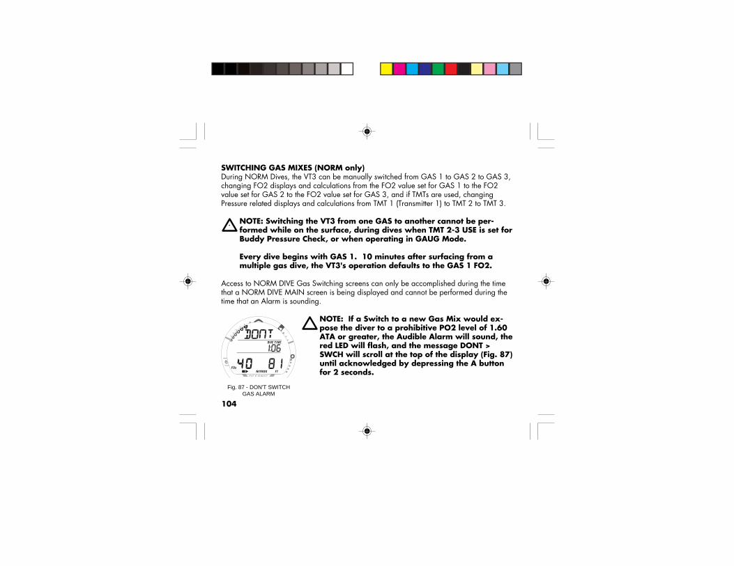
104
SWITCHING GAS MIXES (NORM only)During NORM Dives, the VT3 can be manually switched from GAS 1 to GAS 2 to GAS 3,changing FO2 displays and calculations from the FO2 value set for GAS 1 to the FO2value set for GAS 2 to the FO2 value set for GAS 3, and if TMTs are used, changingPressure related displays and calculations from TMT 1 (Transmitter 1) to TMT 2 to TMT 3.
NOTE: Switching the VT3 from one GAS to another cannot be per-formed while on the surface, during dives when TMT 2-3 USE is set forBuddy Pressure Check, or when operating in GAUG Mode.
Every dive begins with GAS 1. 10 minutes after surfacing from amultiple gas dive, the VT3's operation defaults to the GAS 1 FO2.
Access to NORM DIVE Gas Switching screens can only be accomplished during the timethat a NORM DIVE MAIN screen is being displayed and cannot be performed during thetime that an Alarm is sounding.
NOTE: If a Switch to a new Gas Mix would ex-pose the diver to a prohibitive PO2 level of 1.60ATA or greater, the Audible Alarm will sound, thered LED will flash, and the message DONT >SWCH will scroll at the top of the display (Fig. 87)until acknowledged by depressing the A buttonfor 2 seconds.
Fig. 87 - DON'T SWITCHGAS ALARM

105
Due to the possibility that sufficient air may not be available inthe Switch From tank to complete the dive, the Switch to theprohibitive Mix can still be made. If the Switch is made to theprohibitive Mix while in NORM NO DECO DIVE Mode, theHigh PO2 Alarm will activate. If the Switch is made to theprohibitive Mix while in DECO DIVE Mode, the message HIGH> PO2 will replace the scrolling DECO message until the HighPO2 condition clears.
Switching of Gas Mixes can only to be performed during thetime that a Gas Switch Preview screen is being displayed. Theseare accessed from the TMT 2-3 USE screen.
• Depressing the M button for 2 seconds while viewing aNORM DIVE MAIN screen will access the TMT 2-3 USE(Lead-in) screen displaying the Set Point SELF (Fig. 88). If'bud' is displayed, indicating that the VT3 is set for BuddyPressure Check, a Gas Switch cannot be made.
• Pressing and releasing the M button momentarily (< 2seconds) while the TMT 2-3 USE screen is displayed (withthe setting SELF) will access the GAS 1 Switch Previewscreen.
• The VT3 will revert to the NORM DIVE MAIN screen after10 seconds of no further M button action.
Fig. 88 - GAS SWITCHLEAD-IN
When a switch ismade to anotherGAS, there may bea delay of 5 to 15seconds before theVT3's Receiver picksup the TMT's signal.

106
GAS 1 SWITCH PREVIEW, information includes (Fig. 89) -> Graphic GAS1> TLBG, representing Nitrogen Loading> VARI, if ascending> O2BG, if any> FO2 Set Point for GAS 1 and the symbol FO2> Tank icon, representing GAS 1> Symbol NITROX> Current Depth and symbol FT (or M)
• Press/release the M button momentarily (< 2 seconds) toaccess the GAS 2 Switch Preview Display for 10 seconds.
GAS 2 SWITCH PREVIEW, information includes (Fig. 90) -> Graphic GAS2> TLBG, representing Nitrogen Loading> VARI, if ascending> O2BG, if any> FO2 Set Point for GAS 2 and the symbol FO2> Tank icon representing GAS 2> Symbol NITROX> Current Depth and symbol FT (or M)
• Press/release the M button momentarily (< 2 seconds) toaccess the GAS 3 Switch Preview Display for 10 seconds.
Fig. 89 - GAS 1 SWITCHPREVIEW
Fig. 90 - GAS 2 SWITCHPREVIEW

107
TO SWITCH FO2 FROM GAS 1 TO GAS 2• Depressing the M button for 2 seconds while viewing the
GAS 2 Switch Preview Display will Switch the VT3's FO2from GAS 1 to GAS 2 and the VT3's Receiver from TMT 1to TMT 2 (if active).
• After the switch is made, the NORM DIVE MAIN Displaywill represent GAS 2 (Fig. 91). If TMT 2 is active, Air TimeRemaining is then calculated based on Tank 2's Pressure.
TO SWITCH FO2 FROM GAS 2 BACK TO GAS 1A Switch Back to FO2 GAS 1 can be performed, as follows:
• Press/release the M button momentarily (< 2 seconds) tostep through the Gas Switch Preview screens and accessthe GAS 1 Switch Preview screen.
• Depress the M button for 2 seconds while the GAS 1 SwitchPreview screen is displayed to switch the VT3 from GAS 2back to GAS 1 and the VT3's Receiver from TMT 2 back toTMT 1 (if active).
• After the switch is made, the NORM DIVE MAIN Displaywill represent GAS 1. If TMT 1 is active, Air TimeRemaining is then calculated based on Tank 1's Pressure.
When Switching to aGAS (FO2) associatedwith a Tank that doesnot have an activeTMT, the proceduresand displays will bethe same withoutdisplaying TankPressure.
Fig. 91 - NORM DIVE MAIN(after a Switch to GAS 2)

108
GAS 3 SWITCH PREVIEW, information includes (Fig. 92) -> Graphic GAS3> TLBG, representing Nitrogen Loading> VARI, if ascending> O2BG, if any> FO2 Set Point for GAS 3 and the symbol FO2> Tank icon representing GAS 3> Symbol NITROX> Current Depth and symbol FT (or M)
• Press/release the M button momentarily (< 2 seconds) toaccess the GAS 1 Switch Preview Display.
TO SWITCH FO2 FROM GAS 2 TO GAS 3• Depressing the M button for 2 seconds while viewing the
GAS 3 Switch Preview Display will Switch the VT3's FO2from GAS 2 to GAS 3 and the VT3's Receiver from TMT 2to TMT 3 (if active).
• When the switch is made, the NORM MAIN DIVE Displaywill represent GAS 3. If TMT 3 is active, Air TimeRemaining is then calculated based on Tank 3's Pressure.
• A Switch Back to FO2 GAS 2 can be performed, aspreviously described for switching GAS 2 Back to GAS 1.
Fig. 92 - GAS 3 SWITCHPREVIEW

109
BUDDY PRESSURE CHECK (NORM only)During NORM Dives, the VT3 can be used to check (display)Tank Pressure of 1 or 2 buddies whose TMT Link Codes (SerialNumbers) have been entered as TMT 2 and TMT 3 in the VT3'sSET U menu.
NOTE: Use of the Buddy Pressure Check featurecannot be performed when TMT 2-3 USE is setfor SELF (Gas Switching) or while operating inGAUG Mode.
Access to Buddy Pressure Check screens during dives can onlybe accomplished during the time that a NORM DIVE MAINscreen is being displayed and cannot be performed whileviewing Alternate displays or during the time that an Alarm issounding.
BUDDY PRESSURE CHECK DURING DIVES• Bring the VT3 within 3 feet (1 meter) of the Buddy's
Transmitter.
• Press and hold the M button for 2 seconds while viewing aNORM DIVE MAIN screen to access the TMT 2-3 USEscreen displaying the Set Point bud (Fig. 93). If SELF isdisplayed, indicating that the VT3 is set for FO2 GASSwitching, a Buddy Pressure Check cannot be performed. Fig. 93 - BUDDY PRESSURE
CHECK LEAD-IN

110
• Pressing and releasing the M button momentarily (< 2seconds) while the TMT 2-3 USE (Lead-in) screen isdisplayed (with the setting BUD) will start a Search for BUD1 (TMT 2)) displaying the graphics BUD and SEArCH (Fig.94) for a maximum of 5 seconds.
NOTE: No further button action is required. Thedisplays will change automatically, then revertto the NORM DIVE MAIN Display
• After 5 seconds, or less if BUD 1's (TMT 2's) signal isacquired, the BUD 1 screen will appear displaying thegraphic BUD1 and BUD 1's Pressure (Fig. 95), or thegraphic NotAvAil (Not Available), for 5 seconds.
• After BUD 1's screen has been displayed for 5 seconds, theBUD 2 screen will appear displaying the graphic BUD2and BUD 2's Pressure, or the graphic NotAvAil for 5seconds.
• After BUD 2's screen has been displayed for 5 seconds, thescreen will revert to the NORM DIVE MAIN Display.
Fig. 94 - BUDDY SEARCH
Fig. 95 - BUDDY 1 (TMT 2)PRESSURE CHECK

111
NOTE: The graphic NotAvAil (Not Available)(Fig. 96) indicates that the Buddy is out of rangeor the VT3's TMT 2 (or 3) setting does not matchthe Serial Number of that Buddy's TMT.
BUDDY PRESSURE CHECK ON SURFACEA Buddy Pressure Check can be accomplished when on theSurface by accessing the TMT Status Check screens while theNORM SURF MAIN screen is being displayed.
• Depressing and holding the S button for 2 seconds willactivate the VT3's Receiver and access the TMT Statusscreens and Pressures of the Tanks reporting.
• TMT 2 and TMT 3 Battery Status is not displayed when TMT2-3 USE is set for BUD (Buddy Check).
• If a TMT is not active and linked to the VT3, the messageNotAvAil (Not Available) will appear.
• Each screen will be displayed for 3 seconds.
• The display will then revert to the NORM SURF MAINscreen.
Fig. 96 - BUDDY 2 (TMT 3)PRESSURE CHECK

112
M< 2 sec
GAS 1PREVIEW
M< 2 sec
GAS 2PREVIEW
M2 sec
GAS 3PREVIEW
M< 2 sec
M< 2 sec
Switches fromGas 1/TMT 1 to
Gas 2/TMT 2(after 3 sec)
Switches fromGas 2/TMT 2 to
Gas 3/TMT 3(after 3 sec)
Switches fromGas 3/TMT 3 to
Gas 1/TMT 1(after 3 sec)
Back to NORM DIVE MAIN
BUD1PRESSURE
BUD2PRESSURE
5 sec
TMT 2-3 USESet for SELF
TMT 2-3 USE Set for BUD<< or >>
2 to 5sec
5 sec
BUDSEARCH
M< 2 sec
M2 sec
NORM DIVEMAIN
M2 sec
M2 sec
GASSWITCHING
orBUDDY
PRESSURECHECK

113
NORM POST DIVE MODES
WARNING: Prior to diving with the VT3, youmust also read and understand the OceanicDive Computer Safety and Reference Manual,Doc. No. 12-2262, which provides ImportantWarnings and Safety Recommendations aswell as general product information.
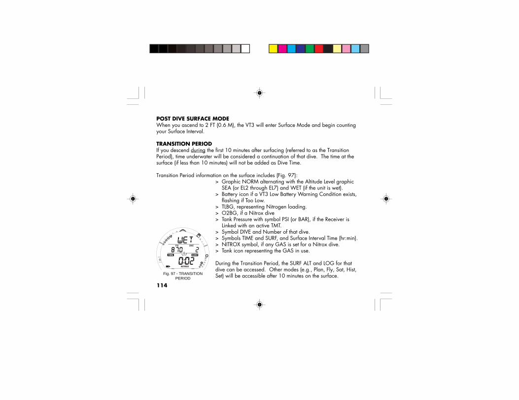
114
POST DIVE SURFACE MODEWhen you ascend to 2 FT (0.6 M), the VT3 will enter Surface Mode and begin countingyour Surface Interval.
TRANSITION PERIODIf you descend during the first 10 minutes after surfacing (referred to as the TransitionPeriod), time underwater will be considered a continuation of that dive. The time at thesurface (if less than 10 minutes) will not be added as Dive Time.
Transition Period information on the surface includes (Fig. 97):> Graphic NORM alternating with the Altitude Level graphic SEA (or EL2 through EL7) and WET (if the unit is wet).> Battery icon if a VT3 Low Battery Warning Condition exists, flashing if Too Low.> TLBG, representing Nitrogen loading.> O2BG, if a Nitrox dive> Tank Pressure with symbol PSI (or BAR), if the Receiver is Linked with an active TMT.> Symbol DIVE and Number of that dive.> Symbols TIME and SURF, and Surface Interval Time (hr:min).> NITROX symbol, if any GAS is set for a Nitrox dive.> Tank icon representing the GAS in use.
During the Transition Period, the SURF ALT and LOG for thatdive can be accessed. Other modes (e.g., Plan, Fly, Sat, Hist,Set) will be accessible after 10 minutes on the surface.Fig. 97 - TRANSITION
PERIOD

115
SURF ALT Display during the Transition Period (Fig. 98) -• To access SURF ALT, press and release the A button (< 2
seconds) while viewing the NORM SURF MAIN display.• Press the S button to activate the SmartGlo Backlight.• Press and release the A button (< 2 seconds) while viewing
the NORM SURF ALT display to access the LOG Previewscreen for that dive.
• The screen will revert to NORM SURF MAIN after 5seconds unless the A button is pressed.
To view that dive's LOG during the Transition Period -• Press and release the A button 2 times (< 2 seconds each)
while viewing the NORM SURF MAIN display to access theLOG Preview screen (Fig. 99).
• Press the S button to view the LOG 1 screen (Nitrogen/Dive data).
• Press the S button again to view the LOG 2 screen (Oxygendata), if a Nitrox dive.
• Press the S button again to return to the NORM SURF MAINscreen.
• The screen will revert to NORM SURF MAIN after 2 minutesif no button is pressed.
Data for that dive will not be stored in the VT3's memory untilthe 10 minute Transition Period on the surface is completed.
Fig. 99 - LOG PREVIEW(during Transition Period)
Fig. 98 - NORM SURF ALT

116
Once 10 minutes have elapsed, the Surface Interval time display colon will stop flashingindicating that the Dive and Transition Period are completed, and a subsequent descentwill be considered a new dive.
AFTER THE TRANSITION PERIODOnce the Transition Period has ended, you will then have full access to other Modes (e.g.,GAUG SURF, FREE SURF, PLAN, FLY, SAT, LOG, HISTORY, SET, etc.).
• To activate the SmartGlo Backlight, press the S button.• To access SURF ALT, PLAN, FLY, etc., press/release the A button as required.
NORM SURF MAIN > GAUG SURF MAIN > FREE SURF MAIN
NORM SURF MAIN > ALT > PLAN > FLY > SAT > LOG > HIST
> The Planning Sequence now displays adjusted No Decompression Limits based onresidual nitrogen and accumulated oxygen calculated to be remaining from theprevious dives.
> The Time to Desaturate counter provides calculated time for tissue desaturation at sealevel.
> If a Violation occurred during the dive, the SAT screen (Desaturation Time) will not bedisplayed.
> After 2 hours on the Surface, FLY > SAT > WET (if the VT3 is wet) alternate.

117
GAUGE OPERATING MODE
WARNING: Prior to diving with the VT3, youmust also read and understand the OceanicDive Computer Safety and Reference Manual,Doc. No. 12-2262, which provides ImportantWarnings and Safety Recommendations aswell as general product information.

118
GAUGE MODEWhen Gauge Mode (GAUG) is selected as the Operating Mode, the VT3 will operate asa Digital Depth Gauge/Timer without performing nitrogen and oxygen calculations.
• To access the GAUG SURF MAIN screen while NORM SURF MAIN is displayed,press the M button for 2 seconds.
• To select GAUG as the Operating Mode to be used, press/release the M button whilethe graphic GAUG is flashing. GAUG stops flashing and GAUG Mode is selected.
• If no GAUG dive has be conducted, press the M button for 2 seconds to access FREESURF MAIN.
NORM SURF MAIN > GAUG SURF MAIN > FREE SURF MAIN
GAUG SURF MAIN Display (Default), information provided includes (Fig. 100) -> Graphic GAUG alternating with the Altitude Level graphic SEA (or EL2 through EL7)
and WET (if the unit is wet).> Battery icon if an VT3 Low Battery Warning Condition exists,flashing if Too Low.> Tank Pressure with symbol PSI (or BAR), if the Receiver is Linked with an active TMT.> Symbol DIVE and Number of that dive.> Symbols TIME and SURF, and Surface Interval Time (hr:min).
• Press the S button to activate the SmartGlo Backlight.• Press/release the A button as necessary to access SURF ALT, FLY, LOG, and HISTORY, similar to NORM Mode.Fig. 100 - GAUG SURF MAIN

119
Fig. 101 - GAUG DIVE MAIN
• Press/hold the A and S buttons simultaneously for 2seconds to access the SET menu (F > A > U > T).
• Press/hold the S button for 2 seconds to access Battery/TMT Status screens.
Upon descending to 5 FT (1.5 M), the VT3 will enter GAUGDIVE Mode.
NOTE: Once a dive is made with the VT3 set forGAUG Operating Mode, you must wait 24 hoursafter surfacing before the VT3 resets and willoperate in NORM Mode (Air or Nitrox) or FREEDive Mode.
GAUG DIVE MAIN Display (Default),information provided includes (Fig. 101) -
> Graphic GAUG.> Tank Pressure with symbol PSI (or BAR), if the Receiver is
Linked with an active TMT.> EDT (hr:min) with symbols DIVE and TIME> Current Depth and FT (or M) icon.
• Press/release the A button to access GAUG DIVE ALT 1.• Depress the A button for 2 seconds to acknowledge/silence
Alarms.• Press the S button to activate the SmartGlo Backlight.
Gas Switchingand BuddyPressure checkscan not be per-formed in GAUGMode.

120Fig. 103 - GAUG DIVE ALT 2
GAUG DIVE ALT 1 Display,information provided includes Fig. 102) -
> Day of the Week graphic (MON, TUE, etc.)> Temperature with degrees icon and graphic F (or C)> Time of Day (hr:min).
• Press/release the A button (< 2 sec) to view GAUG DIVEALT 2.
• The display will revert to the GAUG DIVE MAIN Displayafter 5 seconds unless A is pressed.
GAUG DIVE ALT 2 Display,information provided includes (Fig. 103) -
> Graphic TMT1 (or 2 or 3)> Tank Pressure with the PSI (or BAR) icon, if TMT 1 is active
and linked> EDT (hr:min) with symbols DIVE and TIME> ATR (hr:min) with symbols AIR and TIME, if TMT 1 is active
and linked> ATR (in decrements of 10 min) when =< 60 (min), if TMT 1
is active and linked> Max Depth with icons FT (or M) and MAX
• The display will revert to the GAUG DIVE MAIN screenafter 5 seconds.
Fig. 102 - GAUG DIVE ALT 1

121
FREE DIVE OPERATING MODE
WARNING: Prior to diving with the VT3, youmust also read and understand the OceanicDive Computer Safety and Reference Manual,Doc. No. 12-2262, which provides ImportantWarnings and Safety Recommendations aswell as general product information.
(Refer to additional information on page 159)

122
FREE DIVE MODEWhen FREE (Free Dive Mode) is selected as the Operating Mode, the VT3 will operate asa Digital Depth Gauge with select features.
Nitrogen loading is calculated based upon a default FO2 of AIR and the amount remain-ing during 24 hours is carried over between FREE and NORM Operating Modes.
FREE Mode Alarms and their Set Points are independent of those for NORM and GAUGMode, and they cannot be silenced.
• To access the FREE SURF MAIN screen while NORM GAUG MAIN is displayed (if noGAUG Dive has been conducted, depress the M button for 2 seconds.
• To select FREE as the Operating Mode to be used, press/release the M button whilethe graphic FREE is flashing. FREE stops flashing and FREE Mode is selected.
NORM SURF > GAUG SURF > FREE SURF MAIN
FREE SURF MAIN DISPLAY, information includes (Fig. 104) -> Graphic FREE alternating with the Altitude Level graphic SEA(or EL 2 through EL7) or graphic WET (if wet).> Battery icon if an VT3 Low Battery Warning Condition exists,flashing if Too Low.> Graphic tot - with symbol DIVE and accumulated Total numberof repetitive FREE Dives conducted in that series.> Symbols TIME and SURF and Surface Interval Time (min:secup to 59:59, then hr:min).Fig. 104 - FREE SURF MAIN
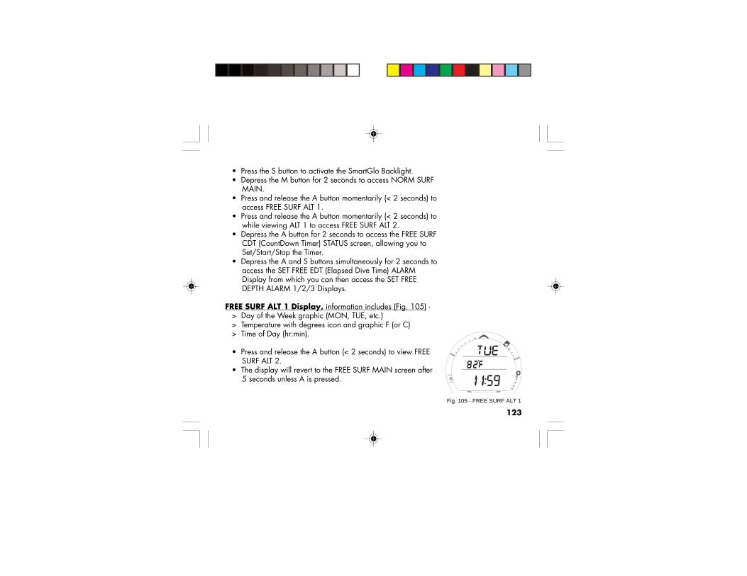
123
• Press the S button to activate the SmartGlo Backlight.• Depress the M button for 2 seconds to access NORM SURF
MAIN.• Press and release the A button momentarily (< 2 seconds) to
access FREE SURF ALT 1.• Press and release the A button momentarily (< 2 seconds) to
while viewing ALT 1 to access FREE SURF ALT 2.• Depress the A button for 2 seconds to access the FREE SURF
CDT (CountDown Timer) STATUS screen, allowing you toSet/Start/Stop the Timer.
• Depress the A and S buttons simultaneously for 2 seconds toaccess the SET FREE EDT (Elapsed Dive Time) ALARMDisplay from which you can then access the SET FREEDEPTH ALARM 1/2/3 Displays.
FREE SURF ALT 1 Display, information includes (Fig. 105) -> Day of the Week graphic (MON, TUE, etc.)> Temperature with degrees icon and graphic F (or C)> Time of Day (hr:min).
• Press and release the A button (< 2 seconds) to view FREESURF ALT 2.
• The display will revert to the FREE SURF MAIN screen after5 seconds unless A is pressed.
Fig. 105 - FREE SURF ALT 1

124
FREE SURF ALT 2 Display, information includes (Fig. 106) -> Graphic FREE> Battery icon if an VT3 Low Battery Warning Condition
exists, flashing if Too Low.> Graphic LASt with symbols DIVE TIME and the Elapsed Dive
Time (min:sec) of the FREE dive previously made while stillin FREE MODE. Resets to 0:00 after 24 hours.
> Symbols MAX and FT (or M) and the Maximum Depth of theFREE dive previously made while still in FREE MODE.
• Press the S button to activate the Backlight.
The display will revert to the FREE SURF MAIN screen after 5seconds.
FREE MODE COUNTDOWN TIMER (CDT)Depressing the A button for 2 seconds while viewing the FREESURF MAIN screen will access the FREE SURF CDT STATUSscreen.
FREE SURF CDT STATUS Display,information includes (Fig. 107) -
> Graphics TIMR and OFF (or ON), flashing> TIME symbol and remaining Countdown time (min:sec) with
the colon flashing, if ON and a CD is in progress.> 0:00 (min:sec) will be displayed with the colon flashing, if
the CD Timer is ON and no time is remaining.Fig. 107 - FREE SURF CDTSTATUS
Fig. 106 - FREE SURF ALT 2

125
> If the CD Timer is OFF, the CD Time (min:sec) previously set will be displayed with thecolon solid.
• Pressing and releasing the S button momentarily (< 2 seconds) will toggle betweenON and OFF.
> If a Time has been set, a toggle from OFF to ON will start the CD Timer indicated bythe colon flashing.
• Press the S button to activate the SmartGlo Backlight.• Pressing/releasing the A button momentarily (< 2 seconds) will revert the Display to
the FREE SURF MAIN screen.• Depressing the A and S buttons simultaneously for 2 seconds while viewing the CD
Timer Status screen when the CD Timer is OFF will access the SET CD TIMER screenwith the MINUTE Set Point flashing.
NOTES: Once the CD TIMER has been Set and Started (by selectingON), it will continue to run in the background while on the surfaceuntil turned OFF (stopped) or the Time reaches 0:00 at which time theAlarm will strike (3 short beeps 3 times), the message TIMR will bedisplayed, and the CD TIMER will revert to OFF.
Upon descending to 5 FT/1.5 M for 5 seconds (i.e., entry into FREEDIVE Mode), CD TIMER operation will continue, if in progress.
During a dive, the CD TIMER can be turned OFF (stopped) and ON(started), but not Set.

126
SET FREE CDT STATUS Display (Surface only),information includes (Fig. 108) -
> Graphics TIMR and SEt, solid.> TIME symbol and Timer setting (min:sec), colon solid,
MINUTE Set Point flashing.
• Depressing and holding the S button while the MINUTE SetPoint is flashing will scroll through the Set Points at a rate of4 per second from 0: to 59: in 1 Minute (1:) increments.
• Pressing and releasing the A button momentarily (< 2seconds) will save the MINUTE Set Point displayed andadvance to Set SECONDS with the Set Point flashing.
• Depressing and holding the S button while the SECONDSSet Point is flashing will scroll through the Set Points at arate of 4 per second from :00 to :59 in 1 Second (:01)increments.
• Pressing and releasing the A button momentarily (< 2seconds) will save the CD Timer Set Point indicated by thegraphic OFF flashing (Fig. 109) in place of the graphic SEt.
• Pressing and releasing S button momentarily (< 2 seconds)will toggle to ON and Start the CD TIMER.
• Pressing the A button momentarily (< 2 seconds, or if the Mbutton is depressed for 2 seconds, or if no button is pressedduring a period of 2 minutes, the Display will revert to theFREE SURF MAIN screen.
Fig. 108 - SET FREE CDT
Fig. 109 - FREE CDT SET(ready to Start)

127
FREE DIVE EDT (ELAPSED DIVE TIME) ALARMThe FREE EDT Alarm is factory set for 30 seconds. When set ON, the Alarm will sound 3short beeps and the message TIME will be displayed momentarily every 30 seconds whilethe VT3 is operating underwater in FREE DIVE Mode.
• Depressing the A and S buttons simultaneously for 2 seconds while the FREE SURFMAIN screen is displayed, will access SET FREE EDT ALARM with the Set Pointflashing.
NOTE: The FREE EDT Alarm can only be Set (turned OFF or ON) whileon the Surface and can not be changed during a Dive.
SET FREE EDT ALARM Display, information includes (Fig. 110) -> Graphic EDT.> Set Point OFF or ON, flashing.
• Pressing and releasing the S button momentarily (< 2seconds) will toggle the Set Point between OFF and ON.
• Pressing the A button momentarily (< 2 seconds) will acceptthe setting and access the SET FREE DEPTH ALARM 1screen.
• Depressing the M button for 2 seconds, or if no button ispressed during a period of 2 minutes, the display will revertto the FREE SURF MAIN screen.
Fig. 110 - SET FREE EDTALARM

128
FREE DIVE DEPTH ALARMS (FDA)The VT3 features 3 FREE Dive DEPTH Alarms that can be Set atprogressively deeper Depths and turned OFF/ON.
> If Alarm 1 is set OFF, then Alarms 2 and 3 will be disabled.> If Alarm 2 is set OFF, Alarm 3 will be disabled.
When each of the Depths are reached during a dive, 3 shortbeeps will sound 3 times and the message DPTH will be dis-played 3 times.
• Pressing the A button momentarily (< 2 seconds) while theSET FREE EDT ALARM screen is displayed will access SETFREE DEPTH ALARM 1 with the Set Point flashing.
Sequence of FREE Mode Alarm Setting Access:
FREE SURF MAIN • press A and S 2 seconds >>>>SET FREE EDT AL • press A less than 2 seconds >>>>SET FREE DEPTH AL 1 • press A less than 2 seconds >>>>SET FREE DEPTH AL 2 • press A less than 2 seconds >>>>SET FREE DEPTH AL 3 • press A less than 2 seconds >>>>FREE SURF MAIN
Responsible

129
SET FREE DEPTH ALARM 1 (FDA 1) Display,information includes (Fig. 111) -
> Graphic FDA1.> Set Point ON or OFF, flashing.> Depth Set Point graphic value, flashing if ON is displayed.> Symbols MAX and FT (or M).
• Pressing and releasing the S button momentarily (< 2seconds) will toggle the Set Point between ON and OFF.
• If set ON, the Depth value displayed will flash.> Pressing and releasing the S button momentarily and
repeatedly (< 2 seconds each time) will step through the SetPoints from 30 to 330 FT (10 to 100 M) in increments of10 FT (1 M) at a rate of 1 Set Point per press of the button.
> Pressing and holding the S button will scroll through the SetPoints at a rate of 4 Set Points per second until released.
> Pressing the A button momentarily (< 2 seconds) will acceptthe Depth Setting and advance to SET FREE DEPTH ALARM2.
• If set OFF, pressing the A button momentarily will accept theSetting and revert operation to the FREE SURF MAINscreen, bypassing SET FREE DEPTH ALARMS 2 and 3.
• Depressing the M button for 2 seconds, or if no button ispressed during a period of 2 minutes, the display will revertto the FREE SURF MAIN screen. Fig. 111 - SET FREE DEPTH
ALARM 1

130
SET FREE DEPTH ALARM 2 (FDA 2) Display,information includes (Fig. 112) -
> Graphic FDA2.> Set Point ON or OFF, flashing.> Depth Set Point graphic value, flashing if ON is displayed.> Symbols MAX and FT (or M).
• Pressing and releasing the S button momentarily (< 2seconds) will toggle the Set Point between ON and OFF.
• If set ON, the Depth value displayed will flash.> Pressing and releasing the S button momentarily and
repeatedly (< 2 seconds each time) will step through the SetPoints from 40 to 330 FT (11 to 100 M) in increments of10 FT (1 M) at a rate of 1 Set Point per press of the button.
> Pressing and holding the S button will scroll through the SetPoints at a rate of 4 Set Points per second until released.
> Pressing the A button momentarily (< 2 seconds) will acceptthe Depth Setting and advance to SET FREE DEPTH ALARM3.
• If set OFF, pressing the A button momentarily will accept theSetting and revert operation to the FREE SURF MAINscreen, bypassing SET FREE DEPTH ALARM 3.
• Depressing the M button for 2 seconds, or if no button ispressed during a period of 2 minutes, the display will revertto the FREE SURF MAIN screen.Fig. 112 - SET FREE DEPTH
ALARM 2
NOTE: The rangeof available FDA 2Set Points begins atthe next FT/M valuegreater than theFDA 1 Alarm SetPoint.

131
SET FREE DEPTH ALARM 3 (FDA3) Display,information includes (Fig. 113) -
> Graphic FDA3.> Set Point ON or OFF, flashing.> Depth Set Point graphic value, flashing if ON is displayed.> Symbols MAX and FT (or M).
• Pressing and releasing the S button momentarily (< 2seconds) will toggle the Set Point between ON and OFF.
• If set ON, the Depth value displayed will flash.> Pressing and releasing the S button momentarily and
repeatedly (< 2 sec each time) will step through the SetPoints from 50 to 330 FT (12 to 100 M) in increments of10 FT (1 M) at a rate of 1 Set Point per press of the button.
> Pressing and holding the S button will scroll through the SetPoints at a rate of 4 Set Points per second until released.
> Pressing the A button momentarily (< 2 sec) will accept theDepth Setting and advance to SET FREE DEPTH ALARM 3.
• If set OFF, pressing the A button momentarily will accept theSetting and revert operation to the FREE SURF MAINscreen.
• Depressing the M button for 2 seconds, or if no button ispressed during a period of 2 minutes, the display will revertto the FREE SURF MAIN screen.
Fig. 113 - SET FREE DEPTHALARM 3
NOTE: The rangeof available FDA 3Set Points begins atthe next FT/M valuegreater than theFDA 2 Alarm SetPoint.

132
FREE DIVE MAIN Display (Default),information includes (Fig. 114) -
> Graphic FREE> TLBG, if any Nitrogen remaining from previous NORM or
FREE Dives conducted within the previous 24 hours.> Temperature with degrees symbol and graphic F (or C)> Elapsed Dive Time (hr:min) with symbols DIVE and TIME> Dive Time Remaining (hr:min) with symbols TIME and NDC> Current Depth and symbol FT (or M).
• Press and release the A button momentarily (< 2 seconds) toaccess the FREE DIVE ALT screen for 5 seconds.
• Depress the A button for 2 seconds to access the FREE CDT(Count Down Timer) STATUS screen.
• Press the S button to activate the SmartGlo Backlight.
FREE DIVE ALT Display, information includes (Fig. 115) -> Day of the Week graphic (MON, TUE, etc.)> Temperature with degrees icon and graphic F (or C)> Time of Day (hr:min).
• The display will revert to the FREE DIVE MAIN screen after5 seconds.
Fig. 114 - FREE DIVE MAIN
Fig. 115 - FREE DIVE ALT

133
FREE DIVE CDT STATUS Display,information includes (Fig. 116) -
> Graphics TIMR and OFF (or ON), flashing> TIME symbol and remaining Countdown time (min:sec) with
the colon flashing if ON and a CD is in progress, 0:00with the colon flashing if ON and no time is remaining. IfOFF, the CD Time previously set while on the surface is tobe displayed with the colon solid.
• Pressing and releasing the S button momentarily (< 2seconds) will toggle between OFF and ON. If a Time hasbeen set, a toggle from OFF to ON will Start the CD TIMERindicated by the colon flashing (Fig. 117).
• Pressing the S button will activate the SmartGlo Backlight.• Pressing and releasing the A button momentarily (< 2
seconds) will revert to the FREE DIVE MAIN screen.• If no button is pressed during a period of 10 seconds, the
display will revert to the FREE DIVE MAIN screen.
FREE DIVE ALARMSAll FREE Dive Alarms will sound 3 short beeps (1 or 2 times) anddisplay a graphic Message as an indication that an event isoccurring and as a reminder to view the display to identify theevent. After the beeps have sounded, the Alarm Message willbe replaced with the graphic FREE.
Fig. 116 - FREE DIVE CDTSTATUS (OFF, ready to Start)
Fig. 117 - FREE DIVE CDTSTATUS (ON, Running)

134
FREE DIVE Alarms are separate and unaffected by NORM/GAUG Mode Alarm Settings, and the Alarms that occur in thoseModes are separate and unaffected by FREE DIVE Alarm Set-tings.
FREE CDT (Count Down Timer) ALARMWhen the FREE CDT decreases to 0:00 (min:sec), 3 short beepswill sound 3 times, the red LED will flash, and the Message TIMRwill appear on the display 3 times momentarily (Fig. 118), thenrevert to the Message FREE.
FREE DIVE DEPTH ALARM(S)When Depth reaches the FREE DEPTH ALARM 1 Set Point, 3short beeps will sound 3 times, the red LED will flash, and theMessage DPTH will appear on the display 3 times momentarily(Fig. 119), then revert to the Message FREE.
The beeps and Message will be repeated when Depth reachesthe FREE DEPTH ALARM 2 and 3 Set Points, if set ON.
If Ascent is made above a FREE DEPTH ALARM Set Point andthen a descent is made to a Depth below it, the respective DepthAlarm will sound again.
Fig. 119 - FREE DIVE MAIN(During DEPTH ALARM)
Fig. 118 - FREE DIVE MAIN(During CDT ALARM)

135
FREE DIVE EDT (Elapsed Dive Time) ALARMWhen the FREE EDT Alarm is set ON prior to commencing aFREE Dive, 3 short beeps will sound, the red LED will flash, andthe Message TIME will appear on the display momentarily (Fig.120), then revert to the Message FREE.
This FREE DIVE Alarm is factory set to repeat every 30 secondsduring FREE DIVE Mode, when it is set ON prior to the dive.
FREE DIVE TLBG (Tissue Loading Bar Graph) ALARMWhile diving in FREE DIVE Mode, nitrogen accumulation fromthe FREE Dives in that set and any previous NORM Dives con-ducted within 24 hours is displayed as the TLBG.
When Nitrogen Loading increases to the Caution level indicatedby 7 segments displayed as the TLBG and the UP Arrow appear-ing solid, 3 short beeps will sound 3 times, the red LED willflash, and the Message UP > HIGH > NI will appear on thedisplay (Fig. 121).
After the beeps, the Message will continue to scroll until theTLBG recedes to 6 segments at which time the Message willchange to FREE and the UP Arrow will be removed.
Fig. 121 - FREE DIVE MAIN(During TLBG ALARM)
Fig. 120 - FREE DIVE MAIN(During EDT ALARM)

136
ENTRY INTO DECO DURING A FREE DIVEIn the event that Nitrogen Loading increases to the Warninglevel indicated by all segments of the TLBG and O2BG and UPArrow flashing, 3 short beeps will sound 3 times, the red LEDwill flash, and the Message UP > VIOL will appear on thedisplay (Fig. 122).
After the beeps, the message UP > VIOL will continue to bedisplayed scrolling until you surface, then the graphic VIOL willalternately be On/Off for 10 minutes after the dive.
Upon surfacing, the UP Arrow will be removed, however, the FullTLBG and O2BG will continue to flash for 24 hours (Fig. 123).
Operation will be as Permanent Violation Mode and access toNORM and GAUG Modes will be blocked until a full 24 hourselapse with no diving.
NOTES:Nitrogen (TLBG) and Oxygen (O2BG) are carriedover between FREE and NORM Modes.
Dive Time Remaining (until Deco or High O2) iscalculated during FREE Mode based FO2 of Air,but not displayed.
Fig. 122 - FREE DIVE MAIN(During DECO)
Fig. 123 - FREE SURF MAIN(During DECO)

137
WARNING: Prior to diving with the VT3, youmust also read and understand the OceanicDive Computer Safety and Reference Manual,Doc. No. 12-2262, which provides ImportantWarnings and Safety Recommendations aswell as general product information.
REFERENCE

138
UPLOADING SETTINGS AND DOWNLOADING DATAThe VT3 is configured with a Data Port located on the back of the left side that enables it tobe connected to a PC through a USB port using the special Interface Cable supplied.
A USB Driver is provided on the OceanLog CD as part of the Interface System.
The Settings Upload feature can be used to set/change the VT3’s Set A group (Alarms),Set U group (Utilities), and Set T group (Date/Time) using the Interface System. The Set Fgroup (FO2) and FREE Mode Alarms must be entered using the VT3's control buttons.
Information available for retrieval (DownLoad) from the VT3 to the PC OceanLog programincludes dive number, surface interval time, maximum depth, elapsed dive time, start date,start time, lowest temperature under water, sampling rate, dive profile, VT3's set points,pressure, Air Time Remaining, OTU, OTS, ascent rate, TLBG, O2BG, and Gas Switchingevents/pressures/FO2s.
The VT3 checks for the presence of an interface device connection to the Data Port onceevery second while in Surface Mode. Checks are not made if the Wet Activation contactsare wet. Upon sensing an interface connection, the requesting device (PC) connects to theVT3 and is prepared for Upload of settings or Download of data which are then initiatedusing the PC OceanLog program.
Prior to attempting to Download data from your VT3 or Upload Settings to it, review theHELP section of the OceanLog program. Recommended is to print those sections of HELPthat you consider appropriate for your Interface activities.

139
PC compatibility requirements:• IBM®, or compatible, Personal Computer with USB Port• Intel® Pentium 200 MHz or better microprocessor• Microsoft® Windows® 98 Second Edition, ME, NT, 2000, or XP• Super VGA card or compatible video graphics adaptor (256 color or greater) with a
minimum 800 X 600 pixel screen area of display settings• 16MB of available RAM• 20MB of available hard drive storage• Mouse• CD Rom drive• Printer (optional)
For software updates, refer to the Oceanic web site.
www.OceanicWorldwide.com
For support, call OceanLog Support toll free at -
(866) 732-7877, 8 Am to 5 Pm Pacific time.

140
CARE AND CLEANINGProtect your VT3 from shock, excessive temperatures, exposureto chemicals, and tampering. Protect the lens against scratcheswith a Instrument Lens Protector. Small scratches will naturallydisappear underwater.
• Soak and rinse the VT3 in fresh water at the end of eachday of diving, and check to ensure that the areas aroundthe Low Pressure (Depth) Sensor (Fig. 124a), PC InterfaceData Port (Fig. 124b), and Buttons are free of debris orobstructions. Soak and rinse the Regulator(s) with theTransmitter(s) attached.
• To dissolve salt crystals, use lukewarm water or a slightlyacidic bath (50% white vinegar/50% fresh water). Afterremoval from the bath, place the VT3 and the Regulator(s)with Transmitter(s) unit under gently running water andtowel dry before storing.
• Transport your VT3 system cool, dry, and protected.
INSPECTIONS AND SERVICEYour VT3 should be inspected annually by an AuthorizedOceanic Dealer who will perform a factory prescribed functioncheck and inspection for damage or wear. To keep the 2 yearlimited warranty in effect, this inspection must be completedone year after purchase (+/- 30 days).
Fig. 124 - VT3 CASE BACK
b
a

141
Oceanic recommends that you continue to have an inspection performed every year toensure it is working properly. The costs of annual inspections are not covered under theterms of the 2 year limited warranty.
To Obtain Service:Take your VT3 system to an Authorized Oceanic Dealer or send it to the nearest OceanicRegional Distributor Facility (page 173).
To return your VT3 system to Oceanic:• Record all dive data in the Log and/or download the data in memory. All data will
be erased during factory service.• Package it using a protective cushioning material.• Include a legible note stating the specific reason for return, your name, address,
daytime phone number, serial number(s), and a copy of your original sales receiptand Warranty Registration Card.
• Send freight prepaid and insured using a traceable method to the nearest OceanicRegional Service Facility, or to Oceanic USA.
• If shipping to Oceanic USA, obtain an RA (Return Authorization) number bycontacting Oceanic at 510/562-0500 or send an e-mail to [email protected].
• Non-warranty service must be prepaid. COD is not accepted.• Additional information is available at the Oceanic web site OceanicWorldwide.com

142
BATTERY REPLACEMENT
NOTE: The procedures that follow must be closely adhered to. Dam-age due to improper Battery replacement is not covered by the VT3's2 year warranty.
When replacing the Battery in the VT3, it is recommended that youalso replace the Battery(s) in the Transmitter(s), and vice-versa.
The Battery Compartment(s) should only be opened in a dry and clean environment withextreme care taken to prevent the entrance of moisture or dust.
As an additional precautionary measure to prevent formation of moisture in the BatteryCompartment(s), it is recommended that the Battery(s) be changed in an environmentequivalent to the local outdoor temperature and humidity (e.g., do not change theBattery(s) in an air conditioned environment then take it outside during a hot sunny day).
Inspect the Buttons, Lens, and Housing(s) to ensure they are not cracked or damaged. Ifthere is any sign of moisture in the VT3 or Transmitter(s), DO NOT attempt to use the VT3for diving (NORM, GAUG, or FREE) until it receives proper service by the Oceanicfactory or an Authorized Regional Distributor.
Hot SwapIf the new Battery can be inserted into the VT3 within 8 seconds after the old one isremoved (referred to as a Hot Swap), settings and nitrogen and oxygen calculations forrepetitive dives will be retained.

143
VT3 Battery Hatch Removal• Locate the Battery Compartment on the back of the module.• While applying steady inward pressure on the clear Battery
Hatch, rotate the Hatch Ring clockwise 10 degrees bypressing on the upper/right arm of the Ring with a smallblade screwdriver (Fig. 125).
NOTE: If available, an adjustable face spannertool or pointed pliers can be used by insertingthe tips of the tool in the small holes in the Ring(Fig. 126).
• Lift the Hatch Ring up and away from the Housing.• Remove the clear Battery Hatch.
VT3 Battery Removal• Remove the Retaining Bar located across the lower portion of
the Battery (Fig. 127a).• Remove the Hatch O-ring. DO NOT use tools• Using care not to damage the Battery Contacts (Fig. 127 b/
c), slide the Battery up and out of the right side of the BatteryCompartment.
NOTE: DO NOT allow a metal object to shortcircuit the top of the Battery which is positive (+)to the negative ( - ) contact of the Compartment.
Fig. 125 - BATTERY HATCHREMOVAL (Tool)
Fig. 126 - ALTERNATEHATCH REMOVAL
Fig. 127 - VT3 BATTERYREMOVAL
a
b
c

144
Transmitter Battery RemovalLocate the Battery Hatch on the End of the Housing:
• Apply a coin to the recessed slot of the Hatch and turn itcounter clockwise out of the Housing (Fig. 128).
• Remove the Battery from the Battery Compartment anddiscard according to local regulations governing disposalof Lithium batteries.
VT3 and Transmitter Inspection• Closely check all of the sealing surfaces for any signs of
damage that might impair proper sealing.• Inspect the Buttons, Lens, and Housing(s) to ensure they are
not cracked or damaged.
WARNING: If damage or corrosion is found,return your VT3 system to an Authorized Oce-anic Dealer, and DO NOT attempt to use it untilit has received factory prescribed service.
• Remove the Battery Hatch O-ring(s) and inspect them forany signs of deterioration or deformity. DO NOT use toolsto remove the O-ring(s).
• To ensure proper sealing, O-ring replacement is highlyrecommended each time a Battery is replaced.
• Closely examine all threads for any signs of damage thatmight prevent proper threading.Fig. 128 - TMT BATTERY
HATCH REMOVAL

145
Inspection (continued) -• Closely examine the inside of the Battery Compartment(s) for any signs of corrosion
indicating entrance of moisture into the unit.• If corrosion is found, return the VT3 system to an Authorized Oceanic Dealer, and DO
NOT attempt to use it until it has received factory service.• If moisture is found, it is best to have the unit inspected and cleaned by an Authorized
Oceanic Dealer.• If it is necessary to clean the Battery Compartment, flush it and all components with a
solution of 50% white vinegar and 50% fresh water. Rinse with fresh water, andallow to dry overnight, or blow dry with a hair dryer set at no heat.
VT3 Battery Installation• Slide a new 3 volt type CR2450 Lithium Battery, negative ( - ) side down into the
Battery Cavity. Slide it in from the right side and ensure that it slides under the contactclip on the left rim of the cavity.
• Orient the Retaining Bar across the lower portion of the Battery and carefully push itdown into position.
• Replace the Hatch O-ring with a new one. This O-ring mustbe a genuine Oceanic part that can be purchased from anAuthorized Oceanic Dealer. Use of any other O-ring willvoid the warranty.
• Lightly lubricate the new Hatch O-ring with silicone greaseand place it on the inner rim of the Battery Hatch. Ensurethat it is evenly seated.
• Slide the Hatch Ring, top portion first (small opening), ontoyour thumb (Fig. 129). Fig. 129 - VT3 BATTERY
INSTALLATION

146
VT3 Battery Installation (continued) -• Carefully place the clear Battery Hatch (with O-ring) into
position on the rim of the Battery Compartment, then press itevenly and completely down into place with your samethumb.
• Maintain the Battery Hatch securely in place and, using yourother hand, slide the Hatch Ring down off your thumb andinto position around the Battery Compartment. The tabs onthe Ring fit down into the slots located at the 2 and 9 o'clockpositions.
• Using your fingers, turn the Ring counter clockwise 5 de-grees until the tabs engage, then tighten it 5 more degreesby turning it counter clockwise with the aide of a small bladescrewdriver or spanner tool, pressing against the upper/leftarm of the Ring (Fig. 130).
Transmitter Battery Installation• Lightly lubricate the new Battery Cap O-ring with silicone
grease and install it onto the Battery Cap. DO NOT rollthe O-ring over the Threads, instead stretch it slightly towork it down over the slotted end of the Cap into theGroove at the Base of the Threads (Fig. 131).
NOTE: The TMT's O-ring must be a genuineOceanic part that can be purchased from anAuthorized Oceanic Dealer.
Fig. 130 - TIGHTENINGVT3 HATCH RING
Fig. 131 - TRANSMITTERO-RING INSTALLATION

147
Transmitter Battery Installation (continued) -• Place a new 3 volt, CR2, Lithium Battery (Duracell model DL-
CR2 or equivalent) positive (+) side down into the BatteryCompartment with the negative end facing up/out (Fig.132).
• Ensure that the Battery is properly oriented and the HatchO-ring is evenly seated around the Battery Hatch.
• Carefully place the Battery Hatch with Spring into theHousing and turn clockwise slowly by hand to ensureproper threading. Apply a coin and tighten until secure.The outer surface of the Battery Hatch should be flush withthe outer surface of the Housing (Fig. 133).
VT3 System Testing• Pressurize the Regulator Assembly (and Transmitter).• Activate the VT3 and watch carefully as it performs a full
diagnostic and battery check, and enters Surface Mode.Observe the LCD display to ensure it is consistently clearand sharp in contrast throughout the screen.
• If any portions of the display are missing or appear dim, orif a Low Battery Condition is indicated, return your VT3 toan Authorized Oceanic Dealer for a complete evaluationbefore attempting to use it.
• Verify that Tank Pressure is displayed.• Verify all Set Points prior to diving.• Press the S button for 2 seconds to check the Status screens.
Fig. 132 - TMT BATTERYORIENTATION
Battery(+) ( - )
Fig. 133 - TMT BATTERYHATCH INSTALLED

148
INSTALLING A TRANSMITTER ON A REGULATORTo install the Transmitter on the Regulator First Stage:
• Remove the existing Pressure Gauge and High PressureHose, or the High Pressure Port Plug from the Port markedHP using the proper size Hex Key.
• Lightly lubricate the O-ring and Threads of the Transmitterfitting with a halocarbon based lubricant such as Christo-Lube MCG111 (provided in Oceanic Battery Kits).
• Thread the Transmitter clockwise by hand into theRegulator's HP Port (Fig. 134) and tighten until secure witha 5/8" open-end wrench.
• Attach the Regulator First Stage to a full Scuba Tank andpressurize by slowly opening the Tank Valve, listening forany indication of air leaking around the Fitting.
• If air leakage is present, DO NOT use, take the completeRegulator Assembly to an Authorized Oceanic dealer forinspection and service.
TRANSMITTER COMPATIBILITY WITH NITROXWhen packaged and shipped from the factory, Oceanic VT3Transmitters are rated for use with compressed Air and/ornitrogen-oxygen (Nitrox) breathing gas mixtures containing up to99% O2 by volume and with 100% O2.
Fig. 134 -INSTALLING ATMT ON A REGULATOR

149
ALTITUDE SENSING AND ADJUSTMENTPrior to the first dive of a series of repetitive dives, ALTITUDE (i.e., Ambient Pressure) ismeasured upon activation and every 15 minutes until a dive is made.
> Measurements are taken every 15 minutes during the 24 hour period after surfacing.> Measurements are only taken when the unit is dry.> Two readings are taken, the second reading 5 seconds after the first. The readings
must be within 1 foot (30 cm) of each other to record that Ambient Pressure as thecurrent ALTITUDE.
The Mathematical Model in the VT3 accounts for the reduced No Decompression diveTime available based on National Oceanic and Atmospheric Administration (NOAA)guidelines.
When diving in high altitude waters from 3,001 to 14,000 feet (916 to 4,270 meters), theVT3 automatically adjusts to these conditions providing corrected Depth, reduced NoDecompression Times, and reduced Oxygen Accumulation Times at intervals of 1,000 feet(305 meters).
No adjustments are made during any time that the Wet Contacts are bridged.
At an elevation of 3,001 feet, Depth Calibration automatically changes from feet ofseawater to feet of fresh water. This is the first adjustment to the Algorithm.

150
When the Conservative Factor feature is set ON, allowable dive times are calculatedbased upon the next higher 3,000 foot (915 meter) Altitude. All adjustments forAltitudes greater than 11,000 feet (3,355 meters) are then made to allowable divetimes for 14,000 feet (4,270 meters). If the Conservative Factor is set ON while atSea Level, calculations are based upon an Altitude of 3,001 feet.
The VT3 will not function above 14,000 feet (4,270 meters).
IMPERIAL NO DECOMPRESSION LIMITS (HOURS:MINUTES) AT ALTITUDE
Altitude 0` 3001` 4001` 5001` 6001` 7001` 8001` 9001`10001`11001`12001`13001`(feet) to to to to to to to to to to to to 3000` 4000` 5000` 6000` 7000` 8000` 9000`10000`11000`12000`13000`14000`Depth(feet)30 4:20 3:21 3:07 2:55 2:45 2:36 2:28 2:21 2:15 2:10 2:04 1:5840 2:17 1:43 1:36 1:30 1:25 1:20 1:16 1:12 1:09 1:06 1:03 1:0150 1:21 1:03 1:00 0:58 0:55 0:52 0:48 0:45 0:43 0:41 0:39 0:3760 0:57 0:43 0:40 0:38 0:36 0:34 0:33 0:31 0:30 0:29 0:28 0:2770 0:40 0:31 0:30 0:28 0:27 0:26 0:24 0:23 0:22 0:20 0:19 0:1880 0:30 0:24 0:23 0:21 0:20 0:19 0:18 0:17 0:16 0:16 0:14 0:1390 0:24 0:19 0:18 0:17 0:16 0:15 0:14 0:13 0:12 0:11 0:10 0:10100 0:19 0:15 0:14 0:13 0:12 0:11 0:10 0:10 0:09 0:09 0:08 0:08110 0:16 0:12 0:11 0:10 0:09 0:09 0:08 0:08 0:08 0:07 0:07 0:07120 0:13 0:09 0:09 0:08 0:08 0:08 0:07 0:07 0:07 0:06 0:06 0:06130 0:11 0:08 0:08 0:07 0:07 0:07 0:06 0:06 0:06 0:06 0:05 0:05140 0:09 0:07 0:07 0:06 0:06 0:06 0:06 0:05 0:05 0:05 0:05 0:05150 0:08 0:06 0:06 0:06 0:05 0:05 0:05 0:05 0:05 0:04 0:04 0:04160 0:07 0:06 0:05 0:05 0:05 0:05 0:05 0:04 0:04 0:04 0:04 0:04170 0:07 0:05 0:05 0:05 0:04 0:04 0:04 0:04 0:04 0:04 0:04 0:03180 0:06 0:05 0:05 0:04 0:04 0:04 0:04 0:04 0:04 0:03 0:03 0:03190 0:05 0:04 0:04 0:04 0:04 0:04 0:04 0:03 0:03 0:03 0:03 0:03

151
PO2 (ATA)0.600.700.800.901.001.101.201.301.401.501.60
Max DurationSingle Exposure
(min) (hr) 720 12.0 570 9.5 450 7.5 360 6.0 300 5.0 240 4.0 210 3.5 180 3.0 150 2.5 120 2.0 45 .75
Max Total Duration24 Hour Day (min) (hr)
720 12.0 570 9.5 450 7.5 360 6.0 300 5.0 270 4.5 240 4.0 210 3.5 180 3.0 180 3.0 150 2.0
OXYGEN EXPOSURE LIMITS (from NOAA Diving Manual)
METRIC NO DECOMPRESSION LIMITS (HOURS:MINUTES) AT ALTITUDE
Altitude 0` 916` 1221` 1526` 1831` 2136` 2441` 2746` 3051` 3356` 3661` 3966`(meters) to to to to to to to to to to to to 915` 1220` 1525` 1830` 2135` 2440` 2745` 3050` 3355` 3660` 3965` 4270`Depth(meters)9 4:43 3:37 3:24 3:10 2:58 2:48 2:39 2:31 2:24 2:18 2:12 2:0712 2:24 1:52 1:44 1:37 1:30 1:25 1:21 1:17 1:13 1:10 1:07 1:0415 1:25 1:06 1:03 1:00 0:57 0:55 0:52 0:49 0:46 0:43 0:41 0:3918 0:59 0:45 0:42 0:40 0:38 0:36 0:34 0:32 0:31 0:30 0:29 0:2821 0:41 0:33 0:31 0:29 0:28 0:27 0:26 0:24 0:23 0:21 0:20 0:1924 0:32 0:26 0:24 0:22 0:21 0:20 0:19 0:18 0:17 0:16 0:15 0:1427 0:25 0:19 0:18 0:17 0:16 0:16 0:14 0:13 0:12 0:12 0:11 0:1030 0:20 0:16 0:15 0:13 0:12 0:12 0:11 0:10 0:10 0:09 0:09 0:0833 0:17 0:12 0:11 0:11 0:10 0:09 0:09 0:08 0:08 0:08 0:07 0:0736 0:14 0:10 0:09 0:09 0:08 0:08 0:07 0:07 0:07 0:06 0:06 0:0639 0:11 0:08 0:08 0:07 0:07 0:07 0:06 0:06 0:06 0:06 0:05 0:0542 0:09 0:07 0:07 0:07 0:06 0:06 0:06 0:05 0:05 0:05 0:05 0:0545 0:08 0:06 0:06 0:06 0:06 0:05 0:05 0:05 0:05 0:05 0:04 0:0448 0:07 0:06 0:06 0:05 0:05 0:05 0:05 0:04 0:04 0:04 0:04 0:0451 0:06 0:05 0:05 0:05 0:05 0:04 0:04 0:04 0:04 0:04 0:04 0:0454 0:06 0:05 0:05 0:04 0:04 0:04 0:04 0:04 0:04 0:03 0:03 0:0357 0:05 0:04 0:04 0:04 0:04 0:04 0:04 0:03 0:03 0:03 0:03 0:03

152
CAN BE USED AS• Dive Computer (Air or Nitrox)• Digital Depth Gauge/Timer• Free Dive activity• With or without up to 3 Transmitters
NO DECOMPRESSION MODELBasis:• Modified Haldanean Algorithm• 12 tissue compartments
Data Base:• Diving Science and Technology (DSAT) - Rogers/
Powell
Dive Computer Performance:• Tissue compartment halftimes (mins.) Spencer’s “M”
values5, 10, 20, 40, 80, 120, 160, 200, 240, 320, 400, 480
• Reciprocal subsurface elimination• 60 minute surface credit control for compartments
faster than 60 minutes• Tissue compartments tracked up to 24 hours after
last dive
Decompression Capabilities (stop ceilings):• 10, 20, 30, 40, 50, and 60 FT
(3, 6, 9, 12, 15, and 18M)
Altitude Algorithm and Oxygen Exposure Limits:• Based on NOAA tables
TRANSMITTERS• Battery and Pressure check
> every 2 minutes when asleep> every 2 seconds when awake
• Startup> Pressure equal or greater than 120 PSI (8 BAR)> Battery equal or greater than 2.75 volts
• Shutdown> Pressure less than 50 PSI (3.5 BAR)
SURFACE SEQUENCE/MODES• NORM/GAUG/FREE Surface Mode• Plan (30 to 190 FT/9 to 57 M) - NORM only• Time to Fly Countdown - NORM/GAUG• Time to Desaturation Countdown - NORM only• Dive Log - NORM/GAUG• History - NORM/GAUG• Battery/Tank Pressure Status - NORM/GAUG• Set FO2, Alarms, Utilities, Time - NORM/GAUG
FREE MODE SETTINGS• Count Down Timer (0:00 to 59:59 min:sec)• Elapsed Dive Time Alarm (Off/On) - fixed every 30 sec• Depth Alarm 1 (30 to 330 FT /10 to 100 M)• Depth Alarm 2 (40 to 330 FT /11 to 100 M)• Depth Alarm 3 (50 to 330 FT /12 to 100 M)• TLBG Alarm - fixed at 7 segments• DECO Alarm - fixed at 8 TLBG segments
SPECIFICATIONS

153
NORM/GAUG SET MODES
• Set F Group (FO2 items): > Factory Settings:• FO2 GAS1 (Air, 21 to 50%) > Air• FO2 GAS2 (Air, 21 to 100%) > Air• FO2 GAS3 (Air, 21 to 100%) > Air• FO2 Default (On/Off) > On
• Set A Group (Alarms):• Audible Alarm / LED Warning (On/Off) > On• Max Depth Alarm (30 to 330 FT /10 to 100 M) > 330 FT• Elapsed Dive Time Alarm (:10 to 3:00 hr:min) > 3:00 (hr:min)• Max TLBG Alarm (1 to 7 segments) > 5 segments (Deco)• Dive Time Remaining Alarm (:00 to :20 min) > :20 (min)• Turn Press Alarm (Off, 1000 to 3000 PSI / 70 to 205 BAR) > Off• End Press Alarm (300 to 1500 PSI / 20 to 105 BAR) > 300 PSI• Max PO2 Alarm (1.20 to 1.60 ATA) > 1.60 (ATA)
• Set U Group (Utilities):• Wet Activation (On/Off) > On• Units of Measure (Imperial / Metric) > Imperial• Safety Stop Time, Depth (Off/3/5 minutes, 10/15/20 FT, 3/4/5/6 M) > 3:00 (min:sec)• Conservative Factor (On/Off) > Off• Backlight Duration (0/5/10 seconds) > :05 (sec)• Sampling Rate (2/15/30/60 seconds) > 15 (sec)• Transmitter 1 Link Code (Off/On, 000000 to 999999) > serial no.• Transmitter 2-3 Use (Self/Bud) > Self• Transmitter 2 Link Code (Off/On, 000000 to 999999) > serial no.• Transmitter 3 Link Code (Off/On, 000000 to 999999) > serial no.
SPECIFICATIONS (CONTINUED)

154
NORM/GAUG SET MODES (continued)
• Set T Group (Time/Date): Factory Settings:• Hour Format (12/24) > 12• Time (hour:min) > actual at factory• Date (year/month/day) > 0101 2006
• VT3 Serial Number• Factory set > actual
NORM No Decompression Dive Displays:• Main (default) - TLBG, O2BG, VARI, ATR, Pressure, Elapsed Dive Time, Dive Time Remaining, Current Depth• Alternate #1 - Day of Week, Temperature, Time of Day (hr:min)• Alternate #2 - TLBG, O2BG, VARI, ATR, TMT #, Pressure, Elapsed Dive Time, Air Time Remaining, Max Depth• Alternate #3 - TLBG, O2BG, VARI, GAS #, Current PO2, FO2 Set Point, Current Depth• Safety Stop - TLBG, O2BG, VARI, ATR, Pressure, Stop Depth, Stop Time, Dive Time Remaining, Current Depth
NORM Decompression Dive Displays:• Main (default) - TLBG, O2BG, VARI, ATR, Stop Depth, Pressure, Stop Time, Total Ascent Time, Current Depth• Alternate #1 - Day of Week, Temperature, Time of Day (hr:min)• Alternate #2 - TLBG, O2BG, VARI, ATR, TMT #, Pressure, Elapsed Dive Time, Air Time Remaining, Max Depth• Alternate #3 - TLBG, O2BG, VARI, GAS #, Current PO2, FO2 Set Point, Current Depth
NORM Violation Modes (displays similar to Deco) - Conditional, Delayed, and Immediate/Violation Gauge
NORM High PO2 (1.20 to 1.60 ATA)
NORM High Oxygen Accumulation (300 OTU per dive / 24 hr)
NORM Gas Switch Preview (TMT 2-3 Use set for Self) - TLBG, O2BG, Gas #, FO2 Set, Current Depth
NORM Buddy Tank Pressure Check (TMT 2-3 Use set for Bud) - BUD #, Pressure
SPECIFICATIONS (CONTINUED)

155
SPECIFICATIONS (CONTINUED)GAUG Dive Displays:• Main (default) - graphic GAUG, VARI, Pressure, Elapsed Dive Time, Current Depth• Alternate 1 - Day of Week, Temperature, Time of Day (hr:min)• Alternate 2 - TMT #, VARI, Pressure, Elapsed Dive Time, Air Time Remaining, Max Depth
FREE Dive Displays:• Main (default) - graphic FREE, Temperature, Elapsed Dive Time (min:sec), NDC Time (hr:min), Current Depth• Alternate 1 - Day of Week, Temperature, Time of Day (hr:min)• CDT Status - graphic TIMR (Timer), Timer Setting (On/Off), Countdown Time Remaining (min:sec)
NUMERIC DISPLAYS: Range: Resolution:• NORM/GAUG Dive Number 0 to 24 1• FREE Dive Number 0 to 99 1• Current Depth 0 to 330/399 FT (100/120 M) 1 FT (.1 M )• Maximum Depth 330/399 FT (100/120 M) 1 FT (.1 M)• Gas 1 FO2 Set Point Air, 21 to 50 % 1 %• Gas 2 FO2 Set Point Air, 21 to 100 % 1 %• Gas 2 FO2 Set Point Air, 21 to 100 % 1 %• PO2 Value 0.00 to 5.00 ATA .01 ATA• Dive Time Remaining 0:00 to 9:59 hr:min 1 minute• Air Time Remaining 0:00 to 9:59 hr:min 1 minute• Total Ascent Time 0:00 to 9:59 hr:min 1 minute• No Deco Safety Stop Time 5:00 to 0:00 min:sec 1 second• Decompression Stop Time 0:00 to 9:59 hr:min 1 minute• NORM/GAUG Elapsed Dive Time 0:00 to 9:59 hr:min 1 minute• FREE Elapsed Dive Time 0:00 to 59:59 min:sec 1 second• Surface Interval Time 0:00 to 23:59 hr:min 1 minute• FREE Surface Interval Time 0:00 to 59:59 min:sec 1 second
1:00 to 23:59 hr:min 1 minute• Dive Log Surface Interval 0:00 to 23:59 hr:min 1 minute• Time to Fly 23:50 to 0:00 hr:min* 1 minute
(* starting 10 min after the dive)
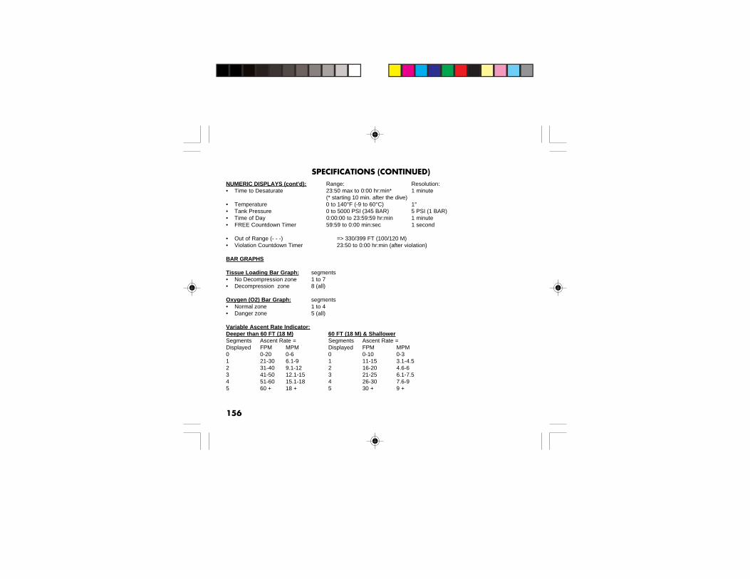
156
NUMERIC DISPLAYS (cont'd): Range: Resolution:• Time to Desaturate 23:50 max to 0:00 hr:min* 1 minute
(* starting 10 min. after the dive)• Temperature 0 to 140°F (-9 to 60°C) 1°• Tank Pressure 0 to 5000 PSI (345 BAR) 5 PSI (1 BAR)• Time of Day 0:00:00 to 23:59:59 hr:min 1 minute• FREE Countdown Timer 59:59 to 0:00 min:sec 1 second
• Out of Range (- - -) => 330/399 FT (100/120 M)• Violation Countdown Timer 23:50 to 0:00 hr:min (after violation)
BAR GRAPHS
Tissue Loading Bar Graph: segments• No Decompression zone 1 to 7• Decompression zone 8 (all)
Oxygen (O2) Bar Graph: segments• Normal zone 1 to 4• Danger zone 5 (all)
Variable Ascent Rate Indicator:Deeper than 60 FT (18 M) 60 FT (18 M) & ShallowerSegments Ascent Rate = Segments Ascent Rate =Displayed FPM MPM Displayed FPM MPM0 0-20 0-6 0 0-10 0-31 21-30 6.1-9 1 11-15 3.1-4.52 31-40 9.1-12 2 16-20 4.6-63 41-50 12.1-15 3 21-25 6.1-7.54 51-60 15.1-18 4 26-30 7.6-95 60 + 18 + 5 30 + 9 +
SPECIFICATIONS (CONTINUED)

157
OPERATIONAL PERFORMANCE
Function: Accuracy:• Depth ±1% of full scale• Timers 1 second per day
Dive Counter:• NORM/GAUG displays Dives #1 to 24, FREE displays Dives #1 to 99 0 if no dive made yet• Resets to Dive #1, upon diving (after 24 hours with no dives)
NORM/GAUG Dive Log Mode:• Stores 24 most recent NORM/GAUG dives in memory for viewing• After 24 dives, adds 25th dive in memory and deletes the older dive
Altitude:• Operational from sea level to 14,000 feet (4,270 meters) elevation• Measures ambient pressure every 30 minutes when not activated, upon activation by push button, and every 15
minutes while in NORM/GAUG/FREE Surface Modes.• Does not measure ambient pressure when Wet.• Compensates for Altitudes above sea level beginning at 3,001 feet (915 meters) elevation and every 1,000 feet
(305 meters) higher.
Conservative Factor:• Reduces NORM and FREE NDLs to those for the Altitude 3,000 feet (915 meters) higher.
Power:• VT3 Battery 1 - 3 vdc, CR2450, Lithium battery• Transmitter Battery 1 - 3 vdc, CR2, .75 Ahr, Lithium battery (Duracell model DL-CR2 or equivalent)• Shelf life Up to 5 years• Replacement User replaceable (annual recommended)• Use Life (VT3) 1 year or 300 dive hours if 2 - 1 hour dives per dive day• Use Life (Transmitter) 300 dive hours if 2 - 1 hour dives per dive day
SPECIFICATIONS (CONTINUED)

158
OPERATIONAL PERFORMANCE (continued) -
Battery Indicator:• Warning - icon on solid at 2.75 volts, VT3 Battery change recommended• Alarm - icon on flashing at 2.50 volts, change the VT3 Battery
Activation:• Manual - push button (recommended), required if Wet Activation is set OFF.• Automatic - by immersion in water (if set ON)• Graphic WET indicates Activation Contacts are Wet (unit must be dried prior to transport or storage)• Cannot be manually activated deeper than 4 FT (1.2 M), if Water Activation is set OFF.• Cannot operate at elevations higher than 14,000 feet (4,270 meters)
Operating Temperature:• Out of the water - between 20 °F and 140 °F (-6 and 60 °C).• In the water - between 28 °F and 95 °F (-2 and 35 °C).• At extremely low temperatures, the LCD may become sluggish, but this will not affect it's accuracy. If stored or
transported in extremely low temperature areas (below freezing), you should warm the unit and its battery withbody heat before diving.
Storage Temperature:• Out of the water - between 14 °F and 158 °F (-8 and 70 °C).
SPECIFICATIONS (CONTINUED)

159
Although breathing apparatus is not utilized for FREE Dive activities, nitrogen tissue loading remains afactor. Nitrogen loading is calculated based upon a fixed FO2 of AIR. Since a user has the option ofalternating between NORM (SCUBA) and FREE Dive activities within a 24 hour period, nitrogencalculations and the displayed value of No Deco Dive Time Remaining (NDC Time) are carried overfrom one operating mode to the other, which permits the user to maintain awareness of nitrogenabsorption and offgasing status.
The mathematical model currently used in the VT3 is based on no decompression/decompressionmultilevel repetitive dive schedules. This algorithm does not take into account the physiologicalchanges associated with the high pressures that competitive type Free diving can expose a diver to.
WARNINGS:• Ensure that you know which Operating Mode is selected (NORM, GAUG, or
FREE) prior to commencing any dive.• Conducting Free dives within a 24 hour period after conducting SCUBA dives,
combined with the effects of multiple rapid Free Dive ascents, increases your riskof decompression sickness. Such activities may result in accelerated entry intodecompression which could cause serious injury or death.
• Combining competitive type Free dive activities that involve multiple descents/ascents with activities utilizing SCUBA during the same 24 hour period is notrecommended. Presently, there is no data relating to such activities.
• It is highly recommended that anyone planning to become involved incompetitive type Free dive activities obtain proper instruction and training froma recognized Free Diving trainer. It is imperative that the physiological affectsbe understood and the diver is physically prepared.
ADDITIONAL INFORMATION PERTAINING TO FREE DIVE MODE

160
INSPECTION / SERVICE RECORD
VT3 Serial Number: _________________________________
Transmitter #1 Serial Number: _________________________________
Transmitter #2 Serial Number: _________________________________
Transmitter #3 Serial Number: _________________________________
Date of Purchase: ____________ Purchased from: __________________________
Below to be filled in by an Authorized Oceanic Dealer:
Date Service Performed Dealer / Technician

161
VT3 FULL LCD
Components:a. Mode/Mix (M) Buttonb. Advance (A) Buttonc. Select (S) Buttond. LED Warning Lighte. TLBGf. VARIg. O2BGh. Symbol - FT or M (Depth)i. Symbol - MAXj. Symbol - NITROXk. Icons - Tank (Gas) 1, 2, 3l. Symbol - FO2m. Air Time Remainingn. Symbols - AIR TIME
TIME NDCTIME O2TIME TATTIME SURF
o. Icon - Ascend Arrowp. Symbol - PSI or BAR (Pressure)q. Icon - Low Batteryr. Icon - degrees (Temperature)s. Symbol - STOP TIME
DIVE TIMEt. Icon - Descend Arrow
r
f
c
d
t
e
g
h
jk
b
q
o
ai
ps
f
m
l
n

162
OCEANIC WORLD WIDE
OCEANIC USA2002 Davis Street
San Leandro, CA 94577Tel: 510/562-0500Fax: 510/569-5404
Web: www.OceanicWorldwide.comE-mail: [email protected]
OCEANIC NORTHERN EUROPEWendelstein, Germany
Tel: +49 (0) 9129 90 99 780 Fax: +49 (0) 9129 90 99 789Web: www.Oceanic.de
E-mail: [email protected]
OCEANIC SOUTHERN EUROPEGenova, Italy
Tel: +39 010 8382006 Fax: +39 010 8365360E-mail: [email protected]
OCEANIC UNITED KINGDOMDevon, United Kingdom
Tel: (44) 1404 891819 Fax: +44 (0) 1404 891909Web: www.OceanicUK.com
E-mail: [email protected]
OCEANIC FRANCE Marseille, France
Tel: 0033.491.25.37.78 Fax: 0033.491.72.34.48E-mail: [email protected]
OCEANIC AUSTRALIASorrento, Victoria, Australia
Tel: 61 3 5984 4770 Fax: 61 3 5984 4307Web: www.OceanicAus.com.au
E-mail: [email protected]
OCEANIC ASIA - PACIFICSingapore
Tel: +65 6391 1420 Fax: +65 6297 5424Web: www.Oceanicasia.com.sg
E-mail: [email protected]
OCEANIC JAPANYokohama Kanagawa-Prev, Japan
Tel: 03-5651-9371Web: www.Oceanic-jp.com
E-mail: [email protected]
OCEANIC HAWAII (Pacific)Kapolei, Hawaii
Tel: 808-682-5488 Fax: 808-682-1068E-mail: [email protected]


VT3
Operating Manual
Doc. No. 12-2705-r04 (7/21/09)
(cover art to be placed on front/back is provided separately)