oco-2 cryocooler development, integration, and test
TRANSCRIPT

1
A. Na-Nakornpanom, D.L. Johnson and B.J. Naylor
Jet Propulsion Laboratory, California Institute of Technology,
Pasadena, CA 91109, USA
ABSTRACT
The Orbiting Carbon Observatory (OCO-2) is currently in its final stages of assembly and
checkout at this time in preparation for a July 2014 launch aboard a Delta II from Vandenberg
Air Force Base in California. OCO-2 is designed to collect space-based global measurements of
atmospheric carbon dioxide (CO2) with the precision, resolution and coverage needed to
characterize regional-scale sources and sinks of this important greenhouse gas. The observatory
consists of a dedicated Orbital Sciences Corporation (OSC) LEOStar-2 spacecraft bus that
carries a single instrument. The instrument uses three HgCdTe focal plane arrays that are cooled
by a Northrop Grumman Aerospace Systems (NGAS) High Efficiency Cryocooler (HEC) pulse
tube cryocooler operating at 110 K. The cryocooler is powered and controlled by the NGAS
Advanced Cryocooler Electronics (ACE).
The development of this cryocooler system was a collaborative effort that involved
qualification and characterization testing at NGAS and JPL, instrument integration at JPL, and
observatory integration at Orbital Sciences Corporation (OSC) in Gilbert, Arizona.
This paper presents the development, characterization, flight qualification and flight
integration test results, including detailed thermal and temperature control performance within
the flight instrument boundary conditions, for the OCO-2 cryocooler system.
NEED ATMOSPHERIC CO2 MEASUREMENTS FROM SPACE – OCO REFLIGHT
In 2002, NASA selected the Orbiting Carbon Observatory mission (OCO) to return space-
based measurements of atmospheric carbon dioxide (CO2) with the sensitivity and spatial and
temporal sampling required to quantify CO2 sources and sinks. This was to be the most
challenging atmospheric trace gas measurement ever attempted from space. While there have
been advances in space-based CO2 measurement capabilities since 2002, including JAXA IBUKI
(GOSAT), no other existing or confirmed satellite sensor can provide the measurements needed
to quantify both CO2 sources and sinks. The unfortunate loss of OCO in early 2009 due to
launch failure delayed delivery of this critical data. OCO measurements are widely viewed as
essential to provide the scientific basis for developing greenhouse gas policies. Meeting the
science and policy imperatives on the needed time scale could only be accomplished by
launching an OCO rebuild on a fast-track schedule that capitalizes on the project’s assets and
innovations.
#34
OCO-2 Cryocooler Development,
Integration, and Test
96
105Cryocoolers 18, edited by S.D. Miller and R.G. Ross, Jr.©¶International Cryocooler Conference, Inc., Boulder, CO, 2014

2
The OCO Project was granted funding to develop OCO-2 starting in June 2009, focused
toward launch on a United Launch Alliance (ULA) Delta II 7320 launch vehicle in Summer
2014 and delivery of exploratory atmospheric CO2 data products to the public as soon as early
2015.
FLIGHT COOLER SYSTEM
The OCO-2 cryocooler system consists of the elements shown in Fig. 1, including the
Thermal Mechanical Unit (TMU), the Cryocooler Control Electronics (CCE) and flight cables
for connecting the TMU and CCE. The CCE is supplied by NGAS, and is the next-generation
Advanced Cryocooler Electronics (ACE) design after the AIRS/TES CCE. The TMU is the
NGAS High Efficiency Cryocooler (HEC), which is a single stage linear pulse tube cooler
designed to provide large refrigeration capabilities (15 W at 110 K) for users. The HEC was
selected because it has similar design features to the original OCO cryocooler with respect to
mechanical, thermal, software and electrical interfaces. This would help facilitate the integration
of the TMU into the OCO-2 instrument.
An ancillary electronics unit, known as the Cryocooler Interface Electronics (CCIE), is the
interface between the CCE and the instrument host electronics. The CCIE allowed the instru-
ment host electronics and software design to remain unchanged from the original OCO. The
spacecraft bus provides power to the CCIE, which in-turn passes the power through to the CCE
after it performs EMI functions such as inrush current suppression. The CCIE also provides an
FPGA that reformats command and telemetry data from the RS-422 interface of the host
instrument to the LVDS interface of the cooler’s ACE electronics.
Table 1 provides the mass of the system components; total weight is 9.5 kg.
Table 1. OCO-2 Cooler Hardware Weight Breakdown
TMU CCE CCIE Cables
Weight, kg 4.112 3.819 0.904 0.684
TMU
CCE
CCIE
Figure 1. OCO-2 Cryocooler System Hardware Installed on Heat Exchangers in TVAC Chamber.
97Medium-Capacity 50-80 K Single-Stage Cryocoolers 106106 MEDIUM-CAPACITY 50-80 K SINGLE-STAGE CRYOCOOLERS

3
Table 2. Thermal Cycle Test Parameters
Hot Cold
Number of
Cycles
ON OFF ON OFF
TMU 323 K for 72 hrs 328 K for 12 hrs 258 K for 40 hrs 253 K for 12 hrs 3
CCE 323 K for 72 hrs 338 K for 8 hrs 253 K for 40 hrs 243 K for 6 hrs 3
CCIE 348 K for 72 hrs 348 K for 6 hrs 238 K for 24 hrs 238 K for 6 hrs 3
Table 3. Cooler Hardware Subjected Loads during Vibration Testing
CCIE CCE TMU
Frequency (Hz) Level Level Level
20 0.026 G2/Hz 0.013 G
2/Hz 0.016 G
2/Hz
20 to 50 +6 dB/octave +6 dB/octave +6 dB/octave
50 to 300 0.16 G2/Hz 0.08 G
2/Hz 0.10 G
2/Hz
300 to 2000 -6 dB/octave -6 dB/octave -6 dB/octave
2000 0.0037 G2/Hz 0.0019 G
2/Hz 0.0023 G
2/Hz
Overall 9.1 Grms 6.4 Grms 7.2 Grms
COOLER FLIGHT QUALIFICATION
Thermal and vibration qualification tests for the TMU and CCE were performed at NGAS,
and thermal and vibration qualification of the CCIE were performed at JPL. The cryocooler
system was thermally cycled to the levels shown in Table 2. Testing of the system before and
after thermal cycling showed no degradation in performance. Random vibration testing was
performed to the levels as shown in Table 3. The CCE was tested at flight acceptance (FA)
level. The components passed vibration testing without difficulty.
EMC tests were performed to determine compliance with the specifications of MIL-STD-
461 as tailored for OCO-2. The system passed CE01/03 conducted emissions tests and
voltage/current ripple transients. The current ripple was measured to be less than 500 mA p-p
(peak-to-peak) from 25 V to 35 V. The highest ripple captured was 215 mA p-p at 29.5 V. The
system passed inrush current requirements. The maximum inrush was below 10 A and
completed in a time duration less than 170 msec. The system passed conducted susceptibility
tests CS01/02, CS06 and ± 3 V voltage transient tests. EMC measurements were generally made
at the high end of input power to demonstrate the highest expected current ripple or emissions.
The TMU was operated at a heat reject temperature of 298 K, and typically at 60-63 W of input
power. No anomalies were noted during testing for all of these EMC tests.
CRYOGENIC SUBSYSTEM
The cryogenic subsystem (CSS), as shown in Fig. 2, provides the interface between the three
mercury cadmium telluride (HgCdTe) focal plane arrays (FPA) and the TMU. The CSS was
designed, manufactured and tested by Space Dynamics Laboratory (SDL). One FPA operates in
the O2 A-band at 0.76 µm and the other two FPAs operate in the CO
2 bands at 1.6 µm and 2.06
µm. The CSS consists of three subassemblies, one for each FPA, and a flexible aluminum foil
thermal link that connects each subassembly to the TMU. Each subassembly provides a
mounting location for an FPA, while thermally isolating each FPA from the instrument optical
bench and thermally coupling the FPAs to the TMU cold block. The FPA mounts consist of
reentrant tri-fold G10 fiberglass/epoxy tube construction and MLI to minimize parasitic heat
loads on the FPAs. With the TMU cold block controlled to 110 K, the CSS is designed to
maintain the three FPAs at the desired temperature of 120 K.
98OCO-2 CRYOCOOLER DEVELOPMENT, INTEGRATION & TEST 107107OCO-2 CRYOCOOLER DEVELOPMENT, INTEGRATION & TEST

4
COOLER CHARACTERIZATION TESTING
Since the three FPAs are to operate at 120 K, the cooler system was characterized for 110 K
isotherms in addition to load lines. The TMU was operated at a single drive frequency of 63 Hz,
which is the optimal drive frequency recommended by NGAS for OCO’s operating conditions.
The data were plotted on multi-variable plots as shown in Figs. 3 and 4 to display the sensitivity
of the cooler’s thermal performance as a function of applied load to the cold block, cold block
temperature, and heat rejection temperature.
Performance tests for the TMU were performed at a nominal reject temperature of 298 K, as
well as at the OCO-2 allowable flight (AFT) limits of 303 K and 273 K. The measured
performance of the TMU at 298 K reject temperature for varying drive levels is shown in Fig. 3.
The performance data are shown in Fig. 4 for both hot and cold plateaus of 303 K and 273 K,
respectively. These data show that for a 30 K change in heat reject temperature, there is a 350
mW change in refrigeration performance at 110 K.
With the heat load from the CSS to the TMU at the beginning of the mission expected to be
2.4 W at 110 K, the power at the input to the CCIE is about 45 W, thus meeting the key OCO-2
performance requirement, which requires that the TMU be able to provide cooling to 110 K with
no more than 63 W of power at the input to the CCIE. As a note, the HEC is capable of
delivering seven times this capacity at much higher input power. As a result, the TMU and CCE
will not be operating at their highest possible efficiency at this low input power.
Cold block temperature stability measurements were made while varying input voltage and
varying cryocooler and electronics reject temperatures. Although the CCE is capable of
collecting data every two seconds, the cold block temperature stability measurements were
typically taken at 15 second intervals. The OCO-2 instrument host electronics is limited to
sampling CCE data at 80 second intervals.
Two sets of input voltage variations were performed; either 1) the input voltage was
manually varied over a 4 V range as anticipated from the battery charging/discharging during a
one orbit period, or 2) the input voltage was varied abruptly to 22V, 25V, 28V or 35V and then
held stable for a period of one orbit at each of these voltages. Input voltage variations had no
effect on the power to the TMU such that the compressor power stayed constant and the cold
block stability remained at or less than 33 mK p-p over a 98 minute period (one orbit). During
reject temperature ramp changes, the reject temperature was increased at a rate of 0.2 K/min
from 273 K to 298 K. The increase in the reject temperature resulted in an increase in the motor
power required by the compressor although the cold block temperature stability remained at or
less than 60 mK p-p over a 98 minute period.
TMU Cold Block Interface
Figure 2. OCO-2 SDL Cryogenic Subsystem.
99, Medium-Capacity 50-80 K Single-Stage Cryocoolers 108108 MEDIUM-CAPACITY 50-80 K SINGLE-STAGE CRYOCOOLERS

5
INSTRUMENT INTEGRATION
After successfully completing qualification and characterization testing, the cryocooler
system was delivered to JPL for integration into the OCO-2 Instrument.
Figure 3. TMU Performance at 298 K Reject Temperature.
Figure 4. TMU Performance at 303 K (solid lines) and 273 K (dashed lines) Reject Temperature.
100OCO-2 CRYOCOOLER DEVELOPMENT, INTEGRATION & TEST 109109OCO-2 CRYOCOOLER DEVELOPMENT, INTEGRATION & TEST

6
The CCIE and CCE were later mounted at observatory-level to one of the six spacecraft
panels on the Orbital Sciences Corporation (OSC) LEOStar-2 spacecraft bus. At instrument-
level, the CCIE and CCE are mounted to a spacecraft simulator panel underneath the instrument
as shown in Fig. 5.
As shown in Fig. 6, the TMU is mounted to a 6061-T6 aluminum heat sink, and variable
conductance heat pipes (VCHP) transport the TMU waste heat to a radiator. The variable
conductance heat pipes are standard aluminum axially extruded heat pipes with ammonia as the
working fluid. The radiator is fabricated from standard aluminum honeycomb sandwich panels
and is painted with common aerospace S13GLO white paint. This heat rejection system will be
controlled in flight to provide a 288 K heat sink for the TMU that is stable to ± 5 K.
WATER OUTGASSING
During instrument integration, the TMU cold block is conductively coupled to the three
FPAs via the SDL cryogenic subsystem (CSS). The cryogenic surfaces of the FPAs, the flexible
thermal link and the TMU cold block are then wrapped with MLI. The innermost layer is a non-
perforated sheet of aluminized mylar that effectively seals the cryogenic surfaces from the
remaining MLI layers and the rest of the instrument shroud. To vent the volume surrounding the
cryo-surface, three 0.25 inch diameter aluminized kapton vent tubes are arranged as shown in
Fig. 7, such that one end is inserted into this volume (and directed to a surface of the flexible
thermal link) and the other end is pointed out into the volume of the instrument shroud.
CCIE
CCE
Figure 5. Bottom of OCO-2 Instrument
(CCIE and CCE).
Vent Tubes
Figure 7. CSS Integration with MLI and Vent Tubes.
TMU
Radiator
VCHPs
Aluminum
Heat Sink
Figure 6. TMU Integrated onto
OCO-2 Instrument.
101, Medium-Capacity 50-80 K Single-Stage Cryocoolers 110110 MEDIUM-CAPACITY 50-80 K SINGLE-STAGE CRYOCOOLERS
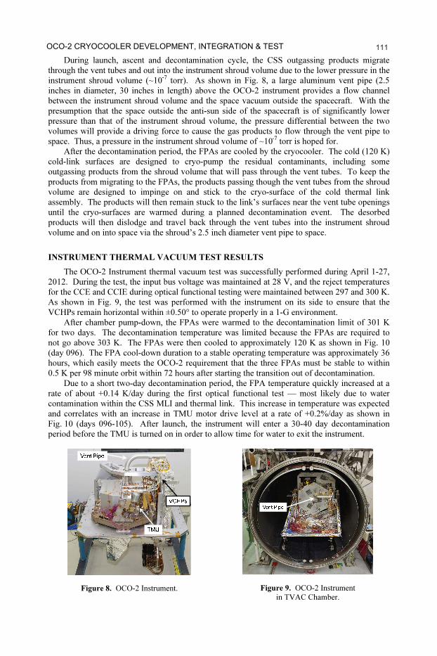
7 During launch, ascent and decontamination cycle, the CSS outgassing products migrate
through the vent tubes and out into the instrument shroud volume due to the lower pressure in the
instrument shroud volume (~10-7
torr). As shown in Fig. 8, a large aluminum vent pipe (2.5
inches in diameter, 30 inches in length) above the OCO-2 instrument provides a flow channel
between the instrument shroud volume and the space vacuum outside the spacecraft. With the
presumption that the space outside the anti-sun side of the spacecraft is of significantly lower
pressure than that of the instrument shroud volume, the pressure differential between the two
volumes will provide a driving force to cause the gas products to flow through the vent pipe to
space. Thus, a pressure in the instrument shroud volume of ~10-7
torr is hoped for.
After the decontamination period, the FPAs are cooled by the cryocooler. The cold (120 K)
cold-link surfaces are designed to cryo-pump the residual contaminants, including some
outgassing products from the shroud volume that will pass through the vent tubes. To keep the
products from migrating to the FPAs, the products passing though the vent tubes from the shroud
volume are designed to impinge on and stick to the cryo-surface of the cold thermal link
assembly. The products will then remain stuck to the link’s surfaces near the vent tube openings
until the cryo-surfaces are warmed during a planned decontamination event. The desorbed
products will then dislodge and travel back through the vent tubes into the instrument shroud
volume and on into space via the shroud’s 2.5 inch diameter vent pipe to space.
INSTRUMENT THERMAL VACUUM TEST RESULTS
The OCO-2 Instrument thermal vacuum test was successfully performed during April 1-27,
2012. During the test, the input bus voltage was maintained at 28 V, and the reject temperatures
for the CCE and CCIE during optical functional testing were maintained between 297 and 300 K.
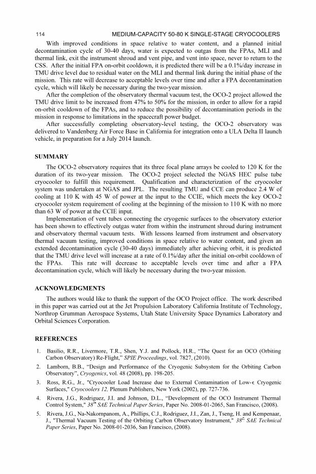
As shown in Fig. 9, the test was performed with the instrument on its side to ensure that the
VCHPs remain horizontal within ±0.50° to operate properly in a 1-G environment.
After chamber pump-down, the FPAs were warmed to the decontamination limit of 301 K
for two days. The decontamination temperature was limited because the FPAs are required to
not go above 303 K. The FPAs were then cooled to approximately 120 K as shown in Fig. 10
(day 096). The FPA cool-down duration to a stable operating temperature was approximately 36
hours, which easily meets the OCO-2 requirement that the three FPAs must be stable to within
0.5 K per 98 minute orbit within 72 hours after starting the transition out of decontamination.
Due to a short two-day decontamination period, the FPA temperature quickly increased at a
rate of about +0.14 K/day during the first optical functional test — most likely due to water
contamination within the CSS MLI and thermal link. This increase in temperature was expected
and correlates with an increase in TMU motor drive level at a rate of +0.2%/day as shown in
Fig. 10 (days 096-105). After launch, the instrument will enter a 30-40 day decontamination
period before the TMU is turned on in order to allow time for water to exit the instrument.
Vent Pipe
TMU
VCHPs
Figure 8. OCO-2 Instrument.
Vent Pipe
Figure 9. OCO-2 Instrument
in TVAC Chamber.
102OCO-2 CRYOCOOLER DEVELOPMENT, INTEGRATION & TEST 111111OCO-2 CRYOCOOLER DEVELOPMENT, INTEGRATION & TEST

8
The CCE firmware monitors an accelerometer that turns off the TMU if acceleration over a
certain threshold is detected. During the first optical functional test, movement of ground
support equipment for optical alignment by personnel above the vacuum chamber produced a
mechanical shock large enough to trip the accelerometer on four separate occasions (days 101-
103). The TMU turned off, which resulted in a rise in FPA temperatures. At no time was the
hardware in any danger, and no temperature violations occurred. The pre-programmed
accelerometer trip level within the CCE was increased per NGAS direction, and the TMU
operated uninterrupted for the rest of the instrument thermal vacuum test.
After testing the performance levels of the VCHPs at hot and cold instrument AFT limits
and a subsequent survival test phase and second decontamination cycle (days 105-110), the FPA
temperatures increased at a rate of about +0.07 K/day. The TMU motor drive level continued to
increase at a rate of +0.2%/day during the second optical functional test (days 110-115). The
decrease in FPA heating rate after the second cycle likely indicates that sufficient water had
outgassed from the FPAs; however water continued to stick to the surface of the MLI and
thermal link.
During the “Day-in-the-Life” test phase (days 115-117), the instrument was subjected to
flight-like variations in boundary temperature. The boundary temperatures were adjusted by
driving the GSE spacecraft simulated panels sinusoidally by ±5 K and driving the VCHP radiator
boundary GSE heat exchanger sinusoidally by ±45 K. This resulted in the TMU reject
temperature shifting by ± 1 K. The resulting temperature response of the FPAs easily met the
OCO-2 requirement that the FPAs must be stable to within 0.5 K per 98 minute orbit.
Throughout the 27-day test, the operating system input power remained within the 63 W
requirement and no increase in the TMU 47% drive limit was required to maintain 110 K.
OBSERVATORY THERMAL VACUUM TEST RESULTS
After successfully completing instrument-level testing, the Instrument was delivered to
Orbital Sciences Corporation in Gilbert, Arizona for integration into the OCO-2 spacecraft. The
CCIE and CCE were mounted to one of the six spacecraft panels on the OSC LEOStar-2
spacecraft bus. The observatory is shown in Fig. 11. As shown in Fig. 12, the test was
performed with the observatory on its side to ensure that the VCHPs remain horizontal within
±0.50° to operate properly in a 1-G environment.
Figure 10. OCO-2 Instrument Thermal Vacuum Test with Cold Block at 110 K.
103Medium-Capacity 50-80 K Single-Stage Cryocoolers 112112 MEDIUM-CAPACITY 50-80 K SINGLE-STAGE CRYOCOOLERS

9
The observatory thermal vacuum test was successfully performed during December 2-19,
2013. After a decontamination period of 60 hours, the FPAs were cooled from decontamination
temperatures of approximately 301 K to 120 K in approximately 21 hours. This easily meets the
OCO-2 requirement that the FPAs be stable to within 0.5 K per 98 minute orbit within 72 hours
after starting the transition out of decontamination.
As shown in Fig. 13, the TMU motor drive level increased at a fast rate of +1.3%/day (again
likely due to the short decontamination period and remaining water contamination within the
CSS) during the spacecraft hot thermal balance test phase (341:14:00 – 342:09:00). With the
TMU reject temperature and optical bench temperature remaining constant, the spacecraft
transitioned to its cold thermal balance test phase (342:09:00 – 344:13:00), resulting in the TMU
motor drive level dropping to a rate of +0.6%/day. After the cold thermal balance test phase was
completed, the spacecraft transitioned into another hot test phase. During this test phase
(344:18:00), the cold block temperature set point was lowered from 110 K to 107.5 K in order to
bring the FPA temperatures closer to the 120 K range. The cold block setpoint change resulted
in the TMU increasing its drive level by 0.8% in order to lower the cold block setpoint by 2.5 K.
Also, the TMU motor drive level dropped its rate to +0.3%/day. As the spacecraft transitioned
into another cold test phase (346:15:00), the TMU motor drive level remained stable
momentarily then continued to rise at a rate of +0.3%/day.
Figure 13. OCO-2 Observatory Thermal Vacuum Test with FPAs at Operating Temperature.
Vent Pipe
Figure 11. OCO-2 Observatory.
Vent Pipe
Figure 12. OCO-2 Observatory in TVAC Configuration.
104OCO-2 CRYOCOOLER DEVELOPMENT, INTEGRATION & TEST 113113OCO-2 CRYOCOOLER DEVELOPMENT, INTEGRATION & TEST
10 With improved conditions in space relative to water content, and a planned initial
decontamination cycle of 30-40 days, water is expected to outgas from the FPAs, MLI and
thermal link, exit the instrument shroud and vent pipe, and vent into space, never to return to the
CSS. After the initial FPA on-orbit cooldown, it is predicted there will be a 0.1%/day increase in
TMU drive level due to residual water on the MLI and thermal link during the initial phase of the
mission. This rate will decrease to acceptable levels over time and after a FPA decontamination
cycle, which will likely be necessary during the two-year mission.
After the completion of the observatory thermal vacuum test, the OCO-2 project allowed the
TMU drive limit to be increased from 47% to 50% for the mission, in order to allow for a rapid
on-orbit cooldown of the FPAs, and to reduce the possibility of decontamination periods in the
mission in response to limitations in the spacecraft power budget.
After successfully completing observatory-level testing, the OCO-2 observatory was
delivered to Vandenberg Air Force Base in California for integration onto a ULA Delta II launch
vehicle, in preparation for a July 2014 launch.
SUMMARY
The OCO-2 observatory requires that its three focal plane arrays be cooled to 120 K for the
duration of its two-year mission. The OCO-2 project selected the NGAS HEC pulse tube
cryocooler to fulfill this requirement. Qualification and characterization of the cryocooler
system was undertaken at NGAS and JPL. The resulting TMU and CCE can produce 2.4 W of
cooling at 110 K with 45 W of power at the input to the CCIE, which meets the key OCO-2
cryocooler system requirement of cooling at the beginning of the mission to 110 K with no more
than 63 W of power at the CCIE input.
Implementation of vent tubes connecting the cryogenic surfaces to the observatory exterior
has been shown to effectively outgas water from within the instrument shroud during instrument
and observatory thermal vacuum tests. With lessons learned from instrument and observatory
thermal vacuum testing, improved conditions in space relative to water content, and given an
extended decontamination cycle (30-40 days) immediately after achieving orbit, it is predicted
that the TMU drive level will increase at a rate of 0.1%/day after the initial on-orbit cooldown of
the FPAs. This rate will decrease to acceptable levels over time and after a FPA
decontamination cycle, which will likely be necessary during the two-year mission.
ACKNOWLEDGMENTS
The authors would like to thank the support of the OCO Project office. The work described
in this paper was carried out at the Jet Propulsion Laboratory California Institute of Technology,
Northrop Grumman Aerospace Systems, Utah State University Space Dynamics Laboratory and
Orbital Sciences Corporation.
REFERENCES
1. Basilio, R.R., Livermore, T.R., Shen, Y.J. and Pollock, H.R., “The Quest for an OCO (Orbiting
Carbon Observatory) Re-Flight,” SPIE Proceedings, vol. 7827, (2010).
2. Lamborn, B.B., “Design and Performance of the Cryogenic Subsystem for the Orbiting Carbon
Observatory”, Cryogenics, vol. 48 (2008), pp. 198-205.
3. Ross, R.G., Jr., "Cryocooler Load Increase due to External Contamination of Low-Ý Cryogenic
Surfaces," Cryocoolers 12, Plenum Publishers, New York (2002), pp. 727-736.
4. Rivera, J.G., Rodriguez, J.I. and Johnson, D.L., “Development of the OCO Instrument Thermal
Control System," 38th SAE Technical Paper Series, Paper No. 2008-01-2065, San Francisco, (2008).
5. Rivera, J.G., Na-Nakornpanom, A., Phillips, C.J., Rodriguez, J.I., Zan, J., Tseng, H. and Kempenaar,
J., "Thermal Vacuum Testing of the Orbiting Carbon Observatory Instrument," 38th SAE Technical
Paper Series, Paper No. 2008-01-2036, San Francisco, (2008).
105Medium-Capacity 50-80 K Single-Stage Cryocoolers 114114 MEDIUM-CAPACITY 50-80 K SINGLE-STAGE CRYOCOOLERS