ocps communication real-time networking and can
TRANSCRIPT

oCPS Communication
Real-time networking and CAN
Courtesy: Damir Isovic, Reinder Bril
adaptations and responsible for current version: Johan Lukkien
1

Networking in CPS context
Heterogeneous
Distributed applications • components even on
different networks
• guarantees and
admission tests
• online adaptation
Open (more than before)
• embedded data available for (new) data oriented applications
• security for privacy and safety
Data and Control: connecting the ‘physical’ to the ‘Cyber’ • information about the physical world to higher layers ICT
• local sensors and actuators
• requirements of power use, throughput, latency, jitter
2

Fieldbus technology
Distributed control
• intended for lowest layer in control system:
connecting PLCs, sensors, actuators
• reduction of wires and complexity
(replaces 4-20mA standard)
• high reliability, predictability; relatively
low data rates and small messages
Networking • physically: bus, ring
• logically: bus (shared medium), mostly
• OSI model: focus on PHY, MAC (LLC) and application layer • messages have application meaning (‘commands’)
• not straightforward to integrate with other networks (or IP)
• PLCs might perform gateway functionality, or be integrated in IP
Standards • IEC 61158, general fieldbus description
• AS-i, CAN, ETHERCAT, LON, PROFIBUS 3
from http://www.profibusaustralia.com.au/

The software substitute
Mechanical and electrical control
systems are replaced by computer
based solutions.
Contributing causes are:
• It is possible to improve already
existing technologies, e.g., brakes in
cars
• It is possible to do things previously
seemed impossible, e.g., drive-by-
wire, electronic stability program in
cars, etc..
• it simplifies the architecture
4

Example: Adaptive Cruise Control
Further development of
the Cruise Control (CC)
Maintains distance to car
in front by slowing down
vehicle.
Radar is used to
measure distance
5

Example: Electronic Damper Control (EDC)
Adjusts shock absorbers in real-time
- better driving comfort
- select drving experience
Relies on a number of sensors • Steering wheel sensor
• Speed sensor
• Acceleration sensors
6

Swing
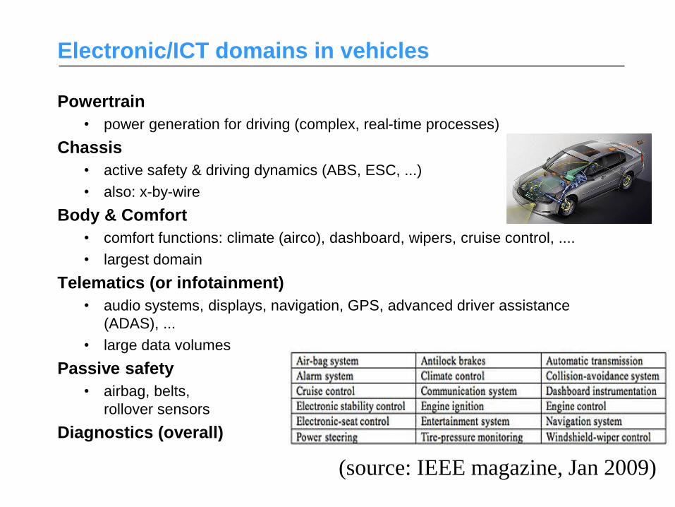
Electronic/ICT domains in vehicles
Powertrain
• power generation for driving (complex, real-time processes)
Chassis
• active safety & driving dynamics (ABS, ESC, ...)
• also: x-by-wire
Body & Comfort
• comfort functions: climate (airco), dashboard, wipers, cruise control, ....
• largest domain
Telematics (or infotainment)
• audio systems, displays, navigation, GPS, advanced driver assistance
(ADAS), ...
• large data volumes
Passive safety
• airbag, belts,
rollover sensors
Diagnostics (overall)
(source: IEEE magazine, Jan 2009)

In-vehicle networks
• Networks of ECUs
• Networks are distinct – avoid application
interference
– requirements for each domain are different
• Applications are distributed over several nodes

AT networks
• LIN – Local Interconnect Network – low speed serial bus, central master
• CAN – Control Area Network (Bosch ‘90) – 1Mbps, serial bus, distributed control, real-time support
• MOST – Media Oriented Systems Transport – > 10Mbps, synchronous, stream oriented
(i.e., not control oriented)
• Byteflight – predecessor of FlexRay, for safety applications
• FlexRay - increase speed and reliability beyond CAN and TTP – 10 Mpbs, strictly timed (static/dynamic part)

Comparison of In-Vehicle Network Protocols, including
Ethernet
From MSc presentation: Siva Thangamuthu, TU/e
Distributed real-time systems require robust real-
time communication
Non real-time systems
• Throughput
• Average response time
• Average latency
Real-time systems • Predictability
• Timing requirements on individual response times and latencies
• Require predictable communications network
• Analysis before the system is operating
Challenge • to construct the computer systems that have at least as good reliability
and safety as the system they are replacing
14

In vehicle (RT) communication
It used to look like this…
As the number of electronic devices grew • the wiring gets more “messy”
• the weight of the car increases
16

Nowadays, it looks like this…
• Cost reduction
• Flexibility
• Functionality
In modern cars,
point-to-point wiring
is replaced by a
common
communication bus
17

Event-trigged communication
Node 1 Node 2
Task A Task B
Task C Task D Task E
Network
event
response
Message
from A to B
18

Time-trigged communication
Node 1 Node 2
Task A Task B
Task C Task D Task E
Network
control sampling
19

”Ordinary” communication protocols
Ethernet • Addressed broadcast messages
• Collision Nodes resend after a
random time
• Impossible to determine transmission
times Not suitable for hard real-
time systems
Token ring • Circulating token
• No collisions
• RT guarantees possible
20

Protocols suitable for RT-communication
TDMA • Time-trigged (periodic)
• Predictable
• High testability
• Example: TTP-protocol
CSMA/CR • Priority based
• Online scheduled
• Flexible
• Example: CAN-protocol
Node 1 Node 2 Node 3 Node 4 Node 1
Max waiting time =
1 TDMA round
Node 1
Node 2
Node 3
Node 4
Collision
resolution
Highest
prio sends
21

CAN – Control Area Network
Originally developed for automotive industry needs
• 1983: BOSCH starts CAN development (Intel joins 1985)
• 1987: First CAN chip
• 1990: First car with CAN (Mercedes S-class)
• 1993: ISO standard
Now used even in industry applications • Very common in machinery
• CAN-controllers developed by Philips, Intel, NEC, Siemens …
An implementation of CSMA/CR • Priority based
• CR is the central mechanism
• Bitwise arbitration to resolve collisions
22
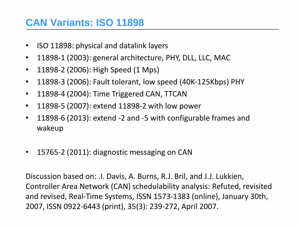
CAN Variants: ISO 11898
• ISO 11898: physical and datalink layers
• 11898-1 (2003): general architecture, PHY, DLL, LLC, MAC
• 11898-2 (2006): High Speed (1 Mps)
• 11898-3 (2006): Fault tolerant, low speed (40K-125Kbps) PHY
• 11898-4 (2004): Time Triggered CAN, TTCAN
• 11898-5 (2007): extend 11898-2 with low power
• 11898-6 (2013): extend -2 and -5 with configurable frames and wakeup
• 15765-2 (2011): diagnostic messaging on CAN
Discussion based on: .I. Davis, A. Burns, R.J. Bril, and J.J. Lukkien, Controller Area Network (CAN) schedulability analysis: Refuted, revisited and revised, Real-Time Systems, ISSN 1573-1383 (online), January 30th, 2007, ISSN 0922-6443 (print), 35(3): 239-272, April 2007.

Structure and function
• Synchronous serial communication
• A shared medium (cable) with connected nodes
• Broadcast – data transmitted as frames can be picked up by all
other attached nodes
• 1 Mbit/s at 40m bus length
• Behaves as an AND-grind: bus value = AND between all bits on
the bus
Node
A
Node
B
Node
C
Node
D
< 40m 1Mbit/s 24

Traffic model
B D
A C
Abstraction of CAN network:
- Frames in priority queues
- No pre-emption
A
B
C
D Resp time
Removed after sending
A single priority queue
that holds all frames
26
Message format
Data frames • Used for data transmission e.g., sampling values from a sensor
• Standard CAN frame (CAN 2.0 A), 11 bits identifier
• Extended CAN frame (CAN 2.0 B), 29 bits identifier
Remote Frames • Used for information requests.
• The transmitting node is asking for information of the type given by
the identifier.
Error frames
• Used for error signaling
Overload Frames
• Used to delay the transmission of the next message frame
• The node sending the Overload Frame is not ready to receive
additional messages at this time
27

CAN-frame (version 2.0 A, standard format)
SOF ID RTR Control Data CRC CRC
DEL
ACK ACK
DEL
EOF IFS
1
bit
11
bits
1
bit
6
bits
0-8
bytes
15
bits
1
bit
1
bit
1
bit
7
bits
min 3
bits
SOF - Start of Frame, start bit (always 0), used for signaling that a frame will be
sent (the bus must be free)
ID - Identifier, identity for the frame and its priority
RTR - Remote Transmission Request
Control - indicates the length of the data field
Data - message data
CRC - Cyclic Redundancy Check,
CRC DEL - CRC delimiter
ACK - Acknowledgement
ACK DEL - ACK delimiter
EOF - End of Frame
IFS - Inter Frame Space, resending wait time
28
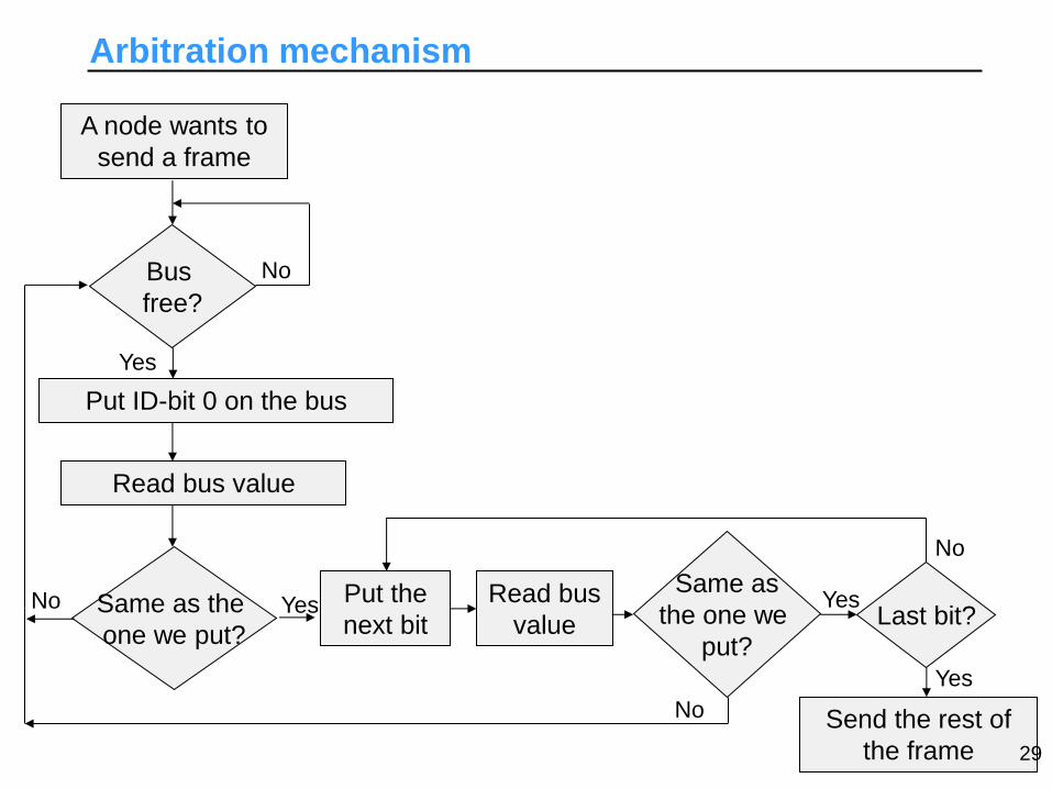
Arbitration mechanism
A node wants to
send a frame
Bus
free?
Put ID-bit 0 on the bus
Read bus value
Same as the
one we put?
Yes
No
No Put the
next bit Yes Read bus
value
Same as
the one we
put?
Last bit?
Send the rest of
the frame
Yes
No
Yes
No
29

Arbitration mechanism
Example:
Assume a simplified CAN-system with only three ID-bits and three nodes A, B, C:
A ID=010
B ID=100
C ID=011
000 – highest priority
111 – lowest priority
which gives:
A-high prio, C-middle, B-low
How does the arbitration look like if the nodes are sending simultaneously?
Bit 0 Bit 1 Bit 2
0
1
0
1
1
0
1
Send the rest of the frame
abort! (bit 0 bus value)
abort! (bit 2 bus value)
Node ID
A
B
C
010
100
011
Bus value: 0 1 0
30

Error handling
Error detection with check sum (CRC) • If the frame is received correctly, the ACK-bit is set to 0 by a receiver
Error signaling • The node that detects an error puts instantly 000000 on the bus
• Because 0 is the dominant value, all nodes will detect the error rapidly
• Some CAN-systems have 1 as the dominant bit bit-pattern for error
signaling is 111111
31

Timing properties
CAN is time deterministic • The latency can be predicted
• Possible to calculate how long time it takes to deliver a frame
How many bits are sent in a CAN-frame?
SOF ID RTR Control Data CRC CRC
DEL
ACK ACK
DEL
EOF IFS
1
bit
11
bits
1
bit
6
bits
0-8
bytes
15
bits
1
bit
1
bit
1
bit
7
bits
min 3
bits
Sum = 47 + 8n
(n = nr of data bytes)
32

Timing properties
We must avoid two bit-patterns that are used for error signaling
i.e., 000000 and 111111: • Bit stuffing: the sender puts extra bits on strategic places to prevent
forbidden bit-patterns
• The receiver reconstruct the original frame by removing the extra bits
Example:
…00101000000101… Original frame:
Sender puts extra bits: …001010000010101…
Receiver removes extra bits: …00101000000101…
Bits sent on the bus: …001010000010101…
33
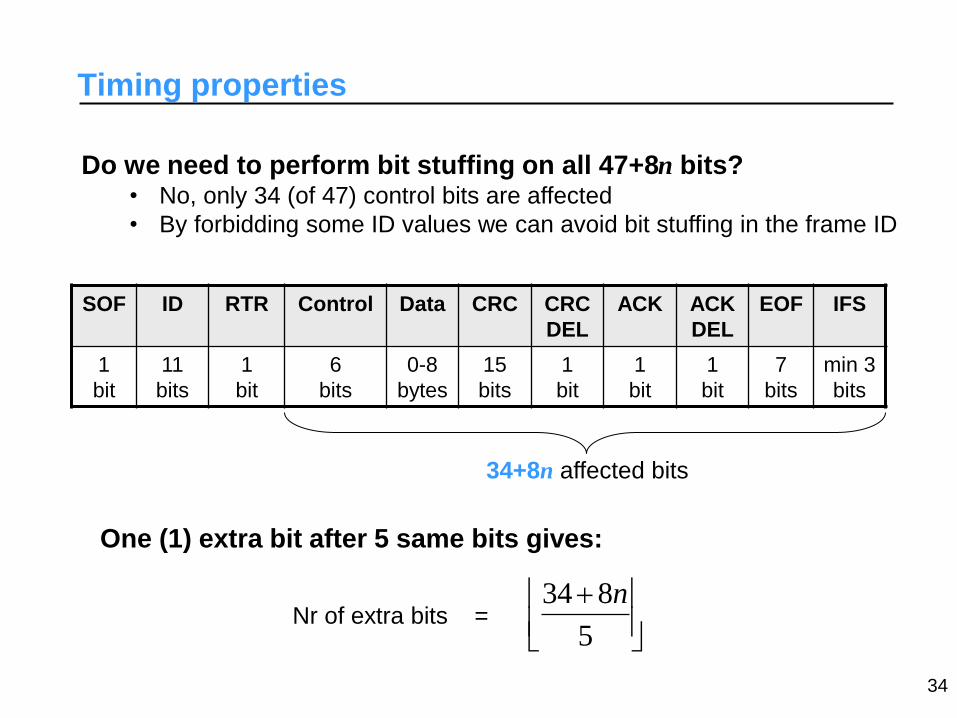
Timing properties
Do we need to perform bit stuffing on all 47+8n bits? • No, only 34 (of 47) control bits are affected
• By forbidding some ID values we can avoid bit stuffing in the frame ID
SOF ID RTR Control Data CRC CRC
DEL
ACK ACK
DEL
EOF IFS
1
bit
11
bits
1
bit
6
bits
0-8
bytes
15
bits
1
bit
1
bit
1
bit
7
bits
min 3
bits
34+8n affected bits
One (1) extra bit after 5 same bits gives:
5
834 n Nr of extra bits =
34
Timing properties
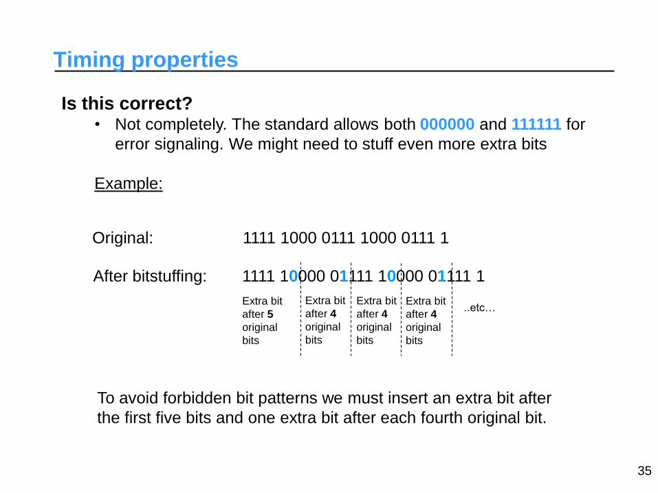
Is this correct? • Not completely. The standard allows both 000000 and 111111 for
error signaling. We might need to stuff even more extra bits
Example:
Original: 1111 1000 0111 1000 0111 1
After bitstuffing:
To avoid forbidden bit patterns we must insert an extra bit after
the first five bits and one extra bit after each fourth original bit.
1111 10000 01111 10000 01111 1
Extra bit
after 5
original
bits
Extra bit
after 4
original
bits
Extra bit
after 4
original
bits
Extra bit
after 4
original
bits
..etc…
35

Timing properties
Hence, the number of extra bits in a CAN-frame is:
4
1834 n
Now we can calculate the total transmission time for a CAN-frame:
bitbiti nn
nWC )1055()4
1834847(
Transmission times for 1Mbit/s (i.e. bit = 1s):
• longest: nmax= 8 and including stuff-bits
ssWCi 1351)8*1055(
36
• shortest: nmin= 0 and without extra bits:
sBCi 47
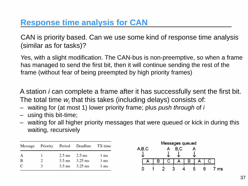
Response time analysis for CAN
CAN is priority based. Can we use some kind of response time analysis
(similar as for tasks)?
Yes, with a slight modification. The CAN-bus is non-preemptive, so when a frame
has managed to send the first bit, then it will continue sending the rest of the
frame (without fear of being preempted by high priority frames)
A station i can complete a frame after it has successfully sent the first bit.
The total time wi that this takes (including delays) consists of: – waiting for (at most 1) lower priority frame; plus push through of i
– using this bit-time;
– waiting for all higher priority messages that were queued or kick in during this
waiting, recursively
37

Response time analysis for CAN
where the blocking time for a frame is given by:
CAN is priority based. Can we use some kind of response time analysis
(similar as for tasks)?
Yes, with a slight modification. The CAN-bus is non-preemptive, so when a frame
has managed to send the first bit, then it will continue sending the rest of the
frame (without fear of being preempted by high priority frames)
j
ihpj j
iibiti WC
T
wBw
)(
Response time for a frame i (pessimistic):
bitiii WCwWR
bitk
ilpki
kilpk
i niWCWC
iWCB 135
)max,max(
1max
)(
)(
1 for
for
hp(i) = high priority frames (that can delay the first bit)
lp(i) = low priority frames (that can block the first bit) 38

Aside: recursive expressions
The recurrence captures the following iterative reasoning:
– consider a minimum approximation time for wi :
– determine how much interference from higher priority tasks is
possible during this w0 . This gives a new approximation
– Continue this process until the new approximation is the same
39
(0)
i bit iw B
(0)(1)
( )
ii bit i j
j hp i j
ww B WC
T

Response time analysis for CAN
Frames can have jitter: - variations in time when a frame is queued
- usually due to the sender task’s jitter
40
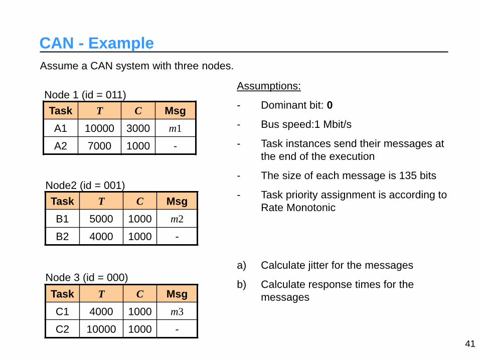
CAN - Example
Assume a CAN system with three nodes.
Task T C Msg
A1 10000 3000 m1
A2 7000 1000 -
Task T C Msg
B1 5000 1000 m2
B2 4000 1000 -
Task T C Msg
C1 4000 1000 m3
C2 10000 1000 -
Node 1 (id = 011)
Node2 (id = 001)
Node 3 (id = 000)
Assumptions:
- Dominant bit: 0
- Bus speed:1 Mbit/s
- Task instances send their messages at
the end of the execution
- The size of each message is 135 bits
- Task priority assignment is according to
Rate Monotonic
a) Calculate jitter for the messages
b) Calculate response times for the
messages
41

CAN - Example
a) Jitter
Node 1:
0
0 4000 20000
7000 14000
WRA1 BRA1
10000 13000
A2
A1
Jm1 = WRA1 – BRA1 = 4000 - 3000 = 1000
Node 2:
(Same as above)
Jm2 = WRB1 – BRB1 = 2000 - 1000 = 1000
Node 3:
Jm3 = WRC1 – BRC1 = 0 (Note: No jitter, because C1 has highest priority)
42
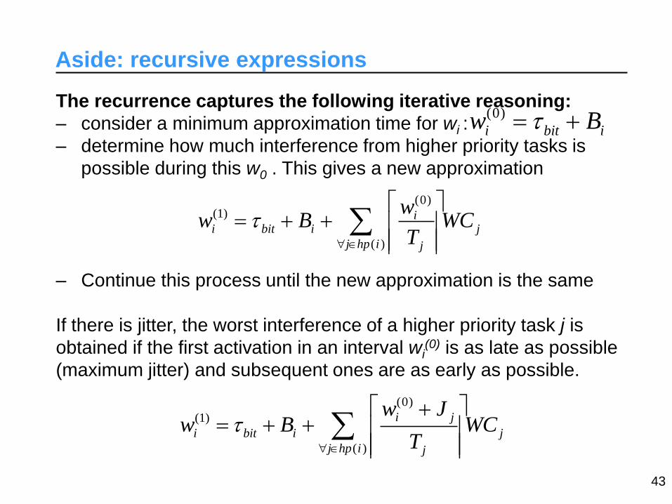
Aside: recursive expressions
The recurrence captures the following iterative reasoning:
– consider a minimum approximation time for wi :
– determine how much interference from higher priority tasks is
possible during this w0 . This gives a new approximation
– Continue this process until the new approximation is the same
If there is jitter, the worst interference of a higher priority task j is
obtained if the first activation in an interval wi(0) is as late as possible
(maximum jitter) and subsequent ones are as early as possible.
43
(0)
i bit iw B
(0)(1)
( )
ii bit i j
j hp i j
ww B WC
T
(0)
(1)
( )
i j
i bit i j
j hp i j
w Jw B WC
T

Response time analysis for CAN
Frames can have jitter: - variations in time when a frame is queued
- usually due to the sender task’s jitter
(finalization (WF) rather than response to indicate interval start as reference)
j
ihpj j
ji
ibiti WCT
JwBw
)(
bitiiii WCwJWF
The equations above can be re-written as (w’i = wi - bit):
j
ihpj j
bitji
ii WCT
JwBw
)(
iiii WCwJWF
44

CAN - Example
Assume a CAN system with three nodes.
Task T C Msg
A1 10000 3000 m1
A2 7000 1000 -
Task T C Msg
B1 5000 1000 m2
B2 4000 1000 -
Task T C Msg
C1 4000 1000 m3
C2 10000 1000 -
Node 1 (id = 011)
Node2 (id = 001)
Node 3 (id = 000)
Assumptions:
- Dominant bit: 0
- Bus speed:1 Mbit/s
- Task instances send their messages at
the end of the execution
- The size of each message is 135 bits
- Task priority assignment is according to
Rate Monotonic
a) Calculate jitter for the messages
b) Calculate response times for the
messages
48

CAN - Example
a) Jitter
Node 1:
0
0 4000 20000
7000 14000
WRA1 BRA1
10000 13000
A2
A1
Jm1 = WRA1 – BRA1 = 4000 - 3000 = 1000
Node 2:
(Same as above)
Jm2 = WRB1 – BRB1 = 2000 - 1000 = 1000
Node 3:
Jm3 = WRC1 – BRC1 = 0 (Note: No jitter, because C1 has highest priority)
49
TTP – Time Triggered Protocol
An implementation of TDMA • Time-trigged
• Bus access is pre-defined in an offline schedule
• Nodes can be assigned several slots
Originally developed on Technical University of Vienna in
corporation with several car manufacturers • Commercial development by TTTech
Aimed for X-by-wire applications • Boeing 777, Airbus 340, Audi,…
Very high demands on reliability • Safety-critical real-time systems that require fault tolerance
55

TTP - typical system configuration
Node
A
Node
B
Node
C
bus 1
bus 2
FTU
Fail Silent nodes
- Nodes detect errors by themselves
- They either deliver correct results or no result at all
Grouped in FTUs (Fail Tolerant Unit)
- Several nodes that do the same in parallel
- FTU is working as long one of the nodes is working
56

Time-trigged clocks must be synchronized
- continuous synchronization
- some tens of microseconds
The receiver compares actual receiving time with expected
receiving time
TTP - synchronization
57

CAN vs TTP
TTP – Time-trigged (periodic)
– Easier analysis
– Predictable
– High testability
CAN – Priority based
– Faster response times for high priority messages
– Flexible
58

Started in year 2000 as an industrial consortium:
BMW, Daimler-Chrysler, Philips and Motorola. Today,
more than 100 members world wide.
Goals and properties • High speed, an order of magnitude higher than
CAN (10Mbps)
• Deterministic communication
• Fault-tolerant communication
• Different connection possibilities
FlexRay
BMW first with FlexRay
in 2006 - a BMW X5
59

Combination of different buses…
State-of-the-art
60

Scheduling in distributed RT
How do we guarantee timing requirements over several nodes with
communication involved?
ALT1: We schedule nodes and communication bus together
– Good control over the system
– Resource effective
– Not flexible the system must be rescheduled for each new node added
ALT2: Each node and communication bus scheduled separately
– Flexible – different parts (nodes) from different manufacturers
– The nodes must have an agreement about the data traffic
61

Example alternative 1: Global schedule
Assume the following design to be scheduled:
Task A
RT = 0
C = 1
Dl = 10
Task E
RT = 0
C = 1
Dl = 10 Task F
RT = 0
C = 1
Dl = 10
Task B
RT = 0
C = 1
Dl = 10
Task D
RT = 0
C = 1
Dl = 10
Task C
RT = 0
C = 1
Dl = 10
Node 1 Node 2
62
RT: relative release time (phasing)

Example alternative 1: Global schedule
Precedence graphs with messages included:
Period = 10
A B C PG 1
D
Period = 10
PG 2
m1
C = 1
D = 10
RT = 0
Node: bus
m2
C = 1
D = 10
RT = 0
Node: bus
E F
63

Example alternative 1: Global schedule
Joint graph:
Period = 10
A B C
D
m1
C = 1
D = 10
RT = 0
Node: bus
m2
C = 1
D = 10
RT = 0
Node: bus
E F
64

Example alternative 1: Global schedule
Schedule:
A B C
D
m1
m2 E F
A E F
0 1 2 3 4 5 6 7 8 9 10
Node 1
B D C Node 2
m1 bus 0 1 2 3 4 5 6 7 8 9 10
m2
0 1 2 3 4 5 6 7 8 9 10
65

Alternative 2: separated scheduling
Event-trigged distributed systems
– Each node scheduled online (examples: RM, EDF)
– No common time basis
– An event-trigged bus (example: CAN)
We want to be able to analyze distributed transactions, ex:
1. A task on a node activated periodically or by an event
2. The task sends a message on the NW
3. The message activates some another task
66
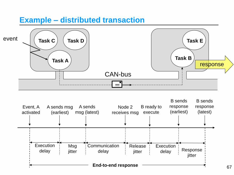
Example – distributed transaction
Event, A
activated
A sends msg
(earliest)
Node 2
receives msg
B ready to
execute
B sends
response
(earliest)
Task A Task B
Task C Task D Task E
CAN-bus
response
event
Execution
delay Communication
delay Release
jitter
Execution
delay
End-to-end response
Msg
jitter
A sends
msg (latest)
67
B sends
response
(latest)
Response
jitter

Distributed transaction – response times
Execution delay of A (= FA) – Caused by A and other tasks on node 1
• Use response time analysis to calculate FA
Message jitter (Jm1) – Caused by variations in A’s execution
• Message jitter = difference between WFA and BFA
Communication delay (= Fm1) – Caused by other messages on the bus
• Use jitter inherited from A (Jm1) and apply response time analysis for CAN
to calculate Fm1
Release jitter for B (JB) – Caused by variations in m1’s transmission
• Release jitter for B = difference between WFm1 and BFm1
• BRm1 47bit (no other messages on the bus)
Execution delay of B (= RB) – Caused by B and other tasks on node 2
• Use jitter inherited from m1 (JB) and calculate response time for B 68

Distributed transaction – response times
AAA
A
A
AAA
JwWF
CT
JwBCw j
hpj j
j
)(
A B m1
j
mhpj j
bitjm
mm CT
JwBw
)1(
1
11
1111 mmmm CwJWF
AA BFWFJm 1
BBB
B
B
BBB
JwWF
CT
JwBCw j
hpj j
j
)(
11 mm BFWFJ B
m1 inherits
jitter from A
B inherits
jitter from m1
69

Conclusions
Today mechanical and electrical control systems are replaced by computer based solutions.
• Challenging to construct the computer systems that have at least as good reliability and safety as the system they are replacing.
• Distributed real-time systems require robust communication
We can use real-time • Predictability • Individual response times and latencies • Analysis before the system is operating
Scheduling of distributed real-time systems
• Require predictable communications networks (CAN, TTP, FlexRay…)
• Either global system scheduling • or separate scheduling on each node and the
communication bus
70

R.I. Davis, A. Burns, R.J. Bril, and J.J. Lukkien,
Controller Area Network (CAN) schedulability
analysis: Refuted, revisited and revised,
Real-Time Systems, ISSN 1573-1383 (online),
http://www.springerlink.com/content/8n32720737877
071/, January 30th, 2007, ISSN 0922-6443 (print),
35(3): 239-272, April 2007.
References
71