october, 1951 - world radio history
TRANSCRIPT

TELEVISISON NEW
'TELEVISION RADAR ELECTRONICS RESEARCH COMMUNICATIONS MICRQWAV
OCTOBER, 1951
RC FILTER CIRCUITS
NUCLEAR PULSE AMPLIFIERS 7
GATE AND DELAY GENERATOR. IO
THE SERIES AMPLIFIER 12
AN INTRODUCTION TO COMPUTER CONCEPTS
14
MAG"ETIC ATTENUATOR 18
PER -CENT RIPPLE NOMOGRAPHS 32
DEPARTMENTS NEW PRODUCTS 20
NEWS BRIEFS 22
PERSONALS 26
PATENT REVIEW 28
TECHNICAL BOOKS 29
CALENDAR 30
ett
g 4V 6NG 0
Copyright. 1951. by Ziff -Davis Publishing Co.
RADIO -ELECTRONIC ENGINEERING Is published each :month as a special section in a limited number of copies of RADIO & TELEVISION NEWS, by the Ziff -Davis Publish- ing Company, 185 N. Wabash Avenue, Chicago I, Illinois.
-e -- The inspection of cathode-ray bulbs for glass strain after seal -In of the electron gun is performed In Ray theon Mfg. Co.'s Cathode -Ray Tube Division in New- ton. Massachusetts, by placing the part to be inspected between the polarized light source and the eyepieces,
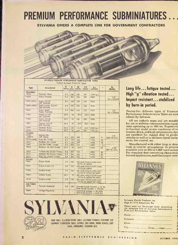
PREMIUM PERFORMANCE SUBMINIATURES ... SYLVANIA OFFERS A COMPLETE LINE FOR GOVERNMENT CONTRACTORS
SYLVANIA PREMIUM PERFORMANCE SUBMINIATURE TUBES *Armed Services Preferred Types
Type Description Ef (Volts)
If (ma)
Eb (Volts)
Ec2 (Volts)
g,, (Nmhos)
u Po (Watts)
PENTODES 5636 Pentode Mixer 6.3 150 100 100 1250(gc)
'5639 Video Pentode 6.3 450 150 100 9000 1.0 (RL=90000)
5840 (5901) Sharp Cut-off UHF Pentode
6.3 150 100 100 5000
'5899 (5900) Semi -remote Cut-off UHF Pentode
6.3 150 100 100 4500
'5902 Audio Beam Power Pentode
6.3 450 110 110 4200 1.0 (RL=30000)
*5905 Sharp Cut-off UHF Pentode
26.5 45 26.5 26.5 2850
*5906 Sharp Cut-off UHF Pentode
26.5 45 100 100 5000
*5907 Remote Cut-off UHF Pentode
26.5 45 26.5 26.5 3000
*5908 Pentode Mixer 26.5 45 26.5 26.5 1000 (gc) *5916 Pentode Mixer 26.5 45 100 100 1280(gc) TRIODES *5718
(5897) Medium Mu UHF Triode 6.3 150 100 5800 27
0.9 (500 Mc Osc)
5719 (5898) High Mu Triode 6.3 150 100 1700 70 5977 Medium Mu Triode 6.3 150 100 4500 16 5987 Low Mu Power Triode 6.3 450 100 1850 4.1
'5904 Medium Mu UFH Triode 26.5 45 26.5 4700 20 0.06 (400 Mc Osc)
6021 Medium Mu Double Triode 6.3 300 100 4800 35 6111 Medium Mu Double Triode 6.3 300 100 4750 20 6112 High Mu Double Triode 6.3 300 100 1850 70 DIODES
*5641 Single Diode 6.3 450 930 peak inverse plate volts 50 ma dc output
5647 Single Diode (T1) 6.3 150 460 peak inverse plate volts 10 ma dc output
'5896 Double Diode 6.3 300 460 peak inverse plate volts 10 ma dc output per plate
*5903 Double Diode 26.5 75 460 peak inverse plate volts 10 ma dc output per plate
6110 Double Diode 6.3 150 460 peak inverse plate volts 4.4 ma dc output per plate
GAS TUBES 5643 Tetrode Thyratron 6.3 150 Average Anode Current = 22 ma
Peak Anode Current = 100 ma *5644 Voltage Regulator - - Operating Voltage = 95 volts
Operating Current = 5-25 ma
SYLUANIA RADIO TUBES; TELEVISION PICTURE TUBES; ELECTRONIC PRODUCTS; ELECTRONIC TEST
EQUIPMENT; FLUORESCENT TUBES, FIXTURES, SIGN TUBING, WIRING DEVICES: LIGHT
BULBS; PHOTOLAMPS; TELEVISION SETS
Long life ...fatigue tested ... High "g" vibration tested... Impact resistant ... stabilized
by burn -in period.
Twenty-five different types of Premium Performance Subminiature Tubes are now offered by Sylvania.
All are cathode types and are suitable for use in military communications equip- ment operating up to 400 mc. Engineered to function under severe conditions of vi- bration, shock, and high temperatures, they are excellent for rugged duty in guidec missiles as well as in military signal equip- ment, fire control, etc.
Manufactured with either long or short leads in circular arrangement. At present. available only on DO or CMP rated orders For complete data concerning characteris- tics and applications, mail the coupon now!
Sylvania Electric Products Inc. Dept. R-1310, Emporium, Pa.
Please send me illustrated folder describing the complete line of Sylvania Subminiature Premium Performance Tubes.
Name
Company
Street
City_-_ _Zone -State L
2 R A D IO- E LE C T R O NI C ENGINEERING OCTOBER, 195U

Rand -pass filters in the 15 to 160 eps range may be designed by the use of RC networks with feedback: amplifiers.
By DAVID FIDELMAN
THE USE OF ELECTRICAL FIL- TER networks has become ex- tremely important in electronic
engineering. Such networks have im- portant applications in all phases of electronics, since they can be designed to give almost any type of frequency cutoff and discrimination characteris- tics. The extensive theory of electronic wave filters and techniques which has been developed for use in their design apply to the design of filters in all fre- quency ranges from low audio to micro- wave frequencies.
However, circuit elements have dif- ferent characteristics at different fre- quencies, therefore the basic filter design equations must be applied dif- ferently in the different frequency ranges. In the middle audio frequen- cies and the low radio frequencies, the circuit elements commonly used in net- works are the standard types of con- densers and iron -core inductors. At microwave frequencies, the components take the form of microwave plumbing, which is reasonably familiar to most electronic engineers. But at the low audio frequencies, there is consider- able difficulty in the design of networks because of the practical difficulties which arise in the design of suitable circuit components.
The equations and formulas for the design of filter networks assume that the
components used are dissipationless and that there are no incidental resistances in the circuit, except for the terminat- ing resistances. In constructing such filters, it is therefore essential to use high -quality coils and condensers with thd least practical amount of dissipa- tion, so that the performance of the completed network will be reasonably close to the theoretical design require- ments. The effects of dissipation are: (a) to cause an insertion loss in the pass band, (b) to decrease the sharp- ness of cutoff, and (c) to cause the peaks of theoretically infinite attenua- tion to be finite. As the dissipation in- creases, these effects become more pro- nounced. At audio frequencies, the ef- fects of dissipation are most closely associated with inductances, and very few problems arise from the use of standard commercial condensers at fre- quencies up to the higher radio frequen- cies. Good results can be attained at audio frequencies above about 100 cycles with the use of good quality toroidal inductances wound on high -permeabili- ty molybdenum-permalloy powder cores. Inductors of this type can be made which have a Q of 50 in the neighbor- hood of 300 to 500 cps, and can have a Q as high as 200 at about 3000 cps.
However, at frequencies below 100 cps their Q may be as low as 10 or less, and it is extremely difficult and expen- sive to construct filters using such in- ductances for low frequencies. Another factor which adds to the difficulty of
A complete band-pass amplifier rack, showing the internal construction.
designing conventional filters for low frequencies is that the capacities re- quired at these frequencies become too large and bulky to be practical.
In many sound and vibration prob- lems it is necessary to construct and use filter networks at these low audio fre- quencies, and in such applications it is therefore necessary to use other elec- tronic principles and techniques to at- tain the same results as with conven- tional filter networks at the higher fre- quencies. The method which is used to achieve these results is by the use of RC networks with feedback amplifiers to form a non -passive type of filter. An example of the application of such methods is in the Sound Analyzing and Measuring System shown in the photo- graphs which accompany this article. In this system (designed and built by the Fairchild Recording Equipment Corp. for . the U. S. Navy Bureau of Ships), the audio spectrum is divided into sharply defined overlapping octave bands from a low frequency limit of 15 cps to an upper frequency of 160 cps. Because of the low frequency at which this equipment must operate it illus- trates the application of the principles to be described in this article.
The meaning of these techniques may be better understood with a brief review of the more conventional filter circuits and their principles of operation. The frequency -selective attenuation charac- teristics of filter networks may be clas- sified into four categories:
OCTOBER, 1951 RADIO -ELECTRONIC ENGINEERING 3

-io
20
z
Z 30 o
¢
40
-50
-60 3
ONE SECTION
Two SECTIONS
THR E
SECTIONS
2
f/fc FOR LOW-PASS SECTIONS
fc/f FOR HIGH-PASS SECTIONS
5
Fig. 1. Ideal frequency response of one, two, and three constant -k filter sections.
(1) low-pass filters, which pass all frequencies up to some finite cutoff fre- quency and attenuate all higher fre- quencies;
(2) high-pass filters, which transmit all frequencies above the cutoff fre- quency and attenuate all lower frequen- cies;
(3) band-pass filters, which transmit a definite band of frequencies and at- tenuate all frequencies outside this band;
(4) band elimination filters, which attenuate a definite band of frequen- cies and transmit all frequencies out- side this band.
Band-pass filters in general can be composed either of band-pass sections, or by suitable combinations of high-pass and low-pass filters. Band -elimination filters are seldom used in practice, and will not be considered further.
Most conventional filters have a lad- der configuration consisting of sym- metrical T or rr sections connected in tandem in sufficient numbers and types to secure the desired attenuation char- acteristic. The simplest basic filter sec- tions are the constant -k filters. Accu- rate curves showing the typical fre-
Fig. 3. Measured amplitude and phase re sponse of typical parallel -T null networks
1.2
J I o Z.B
ó Ñ .6
N .4
Q 1- .2
o
I VOLT NPur 90_ 70 - 50-
Q W J te
-IB)
(A) OUTPUT 30-3; -o 10-+
HASE 10_
!0- u J
UI
.1/40-12
- 90
20 100 IK FREQUENCY IN cps
IOK
quency response which can be obtained from this type of filter can be seen from the curves given in Fig. 1, which show the attenuation characteristics ob- tained from one section, two sections and three sections.
Other types of frequency response can be obtained by use of m derived filter sections, which permit better im- pedance matching to resistive termina- tions and which can have extremely high attenuations at particular fre- quencies in the stop -band. However, the constant -k filter is essentially the limit- ing case of the m -derived filter in which m = 1, and for the purposes of this brief review the properties of conven- tional filters are sufficiently well illus- trated by the constant -k filter. Further properties of such filters, and. of the m -derived sections, may be found in numerous books and articles on the sub- ject of filter theory.
From frequencies of about 100 to 200 cycles and up, practical filters of this type can be constructed which are ca- pable of giving extremely good results, closely approximating almost any fre- quency response characteristic which can be designed from network theory. Below about 100 cycles, the low Q of even the best iron -core inductances and
PARALLEL - T NULL NETWORK
Fig. 2. Parallel -T network and its use in a feedback amplifier stage.
the high values of capacity make it very difficult and quite impractical to use these conventional filters in applications where sharp cutoffs and high attenua- tion slopes are required. At these low frequencies, RC networks must be used in order to attain these desired charac- teristics.
Because of the basic dissipative char- acteristics of resistance -capacity filter sections, any system to achieve the re- quired high attenuation slopes and sharp cutoff characteristics must make use of feedback techniques. This can be done in different ways, and several tech- niques have been developed.
The major problem in the use of RC networks is that they do not give a sharp cutoff. An isolated RC section will give an eventual attenuation of 6 db per octave, but it begins to have ap- preciable attenuation several octaves before this slope is reached. Thus a
e
6
4
o 20 IOO IK
FREQUENCY IN cps
tA)
s' 113)
Fig. 4. (A) Response of stage shown in Fig. 2. (B) Response when condenser C. is shunted from plate to ground (Fig. 5).
4K
filter made up of several such sections will have an attenuation curve whose slope is gradually increasing over a good many octaves, and such a simple system will not give the required flat- ness in the pass band nor sharpness at cutoff. The use of a parallel -T null net- work in a feedback circuit makes avail- able a method of sharpening the attenu- ation characteristic obtained from RC sections.
One type of circuit which places the parallel -T null network at the output of a conventional triode amplifier stage, then applies feedback from the output of the null network back to the input of the amplifier, is shown in Fig. 2. The frequency characteristic of the null net- work by itself is shown in Fig. 3, which gives both the amplitude and phase characteristics. When this network is used in the amplifier circuit with feed- back, the sharpness is considerably in- creased as shown in the response curve A of Fig. 4. The addition of R,, C. and C. to this circuit as shown in Fig. 5 results in the low pass characteristic of Fig. 7. The effect of these elements may be seen better from the curve B of Fig. 4, which shows the response when only C, is added to the circuit, increasing the response below the null frequency and decreasing the response above the null frequency. The addition of the RI, C, section, as shown in Fig. 5, causes a gradual roll -off at the higher frequen- cies, thus lowering the peak below the null and increasing the attenuation at high frequencies to give the resulting
Fig. 5. The addition of R. C and C, to Fig. 2 to give a low-pass circuit.
4 RADIO -ELECTRONIC ENGINEERING OCTOBER, 1951
i
z
+10
o
1
1 10 1
A
BI
1 20
1
1
-30
\ 10 \
r 50
1
I
-60 00 FREQUENCY IN cps
Fig. 6. Comparison of response of LC and RC filters. (A) Two sections of RC circuit of Fig. S with cutoff at 200 cps. (B) Two LC sections of con- stant -k filter with cutoff at 2000 cps.
low-pass characteristics of Fig. 7. A high-pass characteristic is obtained in a similar manner by adding a resistor to ground at the input to the parallel -T network, and reversing the positions of R, and C, in the input section.
When two such sections are used, a sharper cutoff id obtained,'and the curve which results from using two of the low-pass sections of Fig. 5 is shown in the curve A of Fig. 6. This curve has a high initial slope and a frequency of high attenuation, and has an appear- ance somewhat similar to that of an in - derived filter. The dashed curve B is the response of a conventional two -sec- tion constant -k filter with a cut-off fre- quency of 2000 cps, superimposed on the frequency scale of the RC filter for comparison. It can be seen that al- though the RC circuit has a higher ini- tial slope, the over-all attenuation at frequencies well past cutoff is less than that of the constant -k filter. Unfor- tunately, this particular type of circuit is not capable of giving a curve which has these characteristics of the con- stant -k filter.
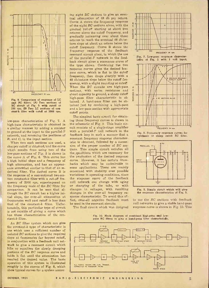
An RC filter system which can give the constant -k type of characteristic is one which uses a sufficient number of isolated RC sections to give the required slope at frequencies far beyond cutoff, in conjunction with a feedback null net- work to give a resonant circuit which lifts or equalizes the slowly drooping portions of the RC response curve and holds it flat until the attenuation has reached the desired value. The basic operation of this system is illustrated roughly in the curves of Fig. 8, which show typical curves for a system assum-
ing eight RC sections to give an even- tual attenuation of 48 db per octave. Curve A shows the frequency response of the eight RC sections alone, with the gradual roll -off starting at about two octaves above the cutoff frequency, and gradually increasing over about three octaves to reach the eventual 48 db/oc- tave slope at about an octave below the cutoff frequency. Curve B shows the frequency response of the feedback resonant circuit alone, in which the use of the parallel -T network in the feed- back circuit gives a resonance curve of the type shown. Combining the two response curves gives the desired low- pass curve, which is flat to the cutoff frequency, then drops sharply with a 48 db/octave slope below the cutoff fre- quency, with a slight rounding at cutoff. When the RC circuits are high-pass sections, with series resistance and shunt capacity to ground, a sharp cutoff high-pass filter characteristic is ob- tained. A band-pass filter can be ob- tained just by combining a high-pass and a low-pass section with appropriate cutoff points.
The simplest basic circuit for obtain- ing these frequency curves is shown in the schematic of Fig. 9. This basic cir- cuit consists of a single -stage amplifier with a parallel -T null network in the feedback loop in such a manner that a resonant frequency response character- istic is obtained, followed by a succes- sion of the proper number of RC sec- tions. This simple circuit satisfies all the conditions which are necessary for the production of the desired response curve. However, it has certain draw- backs which may be undesirable in some applications. These are mainly concerned with stability over possible variations in operating conditions, since the response curve of the feedback null network can change with aging or changing of the tube, or with changes in voltages, with resulting changes in the over-all frequency re- sponse characteristic. To avoid this ef- fect, over-all negative feedback must be used in the resonant circuits.
The final circuit which was designed
.6
.5 Z
Ñ .3
.2
040 100 IK FREQUENCY IN cps
Fig. 7. Low-pass response character- istics of Fig. 5 with 1 volt input.
o
IO
20
z
z !0 á
40
50
-5
I .` A O B
...' \ \ B FEEDBACKALONE CIRCUIT RESONANT
B RC SECTIONS ALONE
'/A
FREQUENCY IN cps
Fig. 8. Frequency response curves for synthesis of sharp cutoff RC filter.
IC
PARALLEL T-T
INPUT
éT1 Fig. 9. Simple circuit which will give the response characteristics of Fig. 8.
to use the RC sections with feedback null networks to give a stable band-pass response curve is shown in Fig. 10. This
Fig. 10. Block diagram of combined high-pass and low- pass RC filters to give a band-pass filter characteristic.
0-10 EA I/ 1
RC
K 5 d5 37115 db VARIABLE RC RESONANT STAGE RC RESONANT STAGE GAIN 5TA E FI F2
RC v6, F- ALL TUBES SHOWN ARE DUAL TRIODES. CONNECTED AS FEEDBACK PAIRS
RC
-1/ I --f I -- GAIN SET
STAGE
vio
VII
POWER STAGE
OCTOBER, 1951 RADIO -ELECTRONIC ENGINEERING 5
r - - - 1
1
1
r Iz
-----
. O9 1nJlnO
MMIM,A ;< +
099
n Oct
099
o
095
O95
099
095
095
9
o:
I 2
21
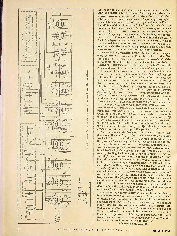
system is the one used to give the octave band-pass char- acteristic required for the Sound Analyzing and Measuring System mentioned earlier, which gives sharp cutoff char- acteristics at frequencies as low as 15 cps. A photograph of a complete band-pass filter of this type is shown in Fig. 13. The design and construction of the filters is such that the same amplifier chassis is used for all frequency bands, with the RC filter components, mounted in four plug-in cans, so that the frequency characteristic is determined by the par- ticular set of filter cans which is plugged into the amplifier. Each band-pass filter is mounted on a separate plug-in chassis, and ten such filters mount in one relay -rack cabinet together with other associated equipment to form a complete measurement range covering one frequency decade.
The complete schematic circuit diagram of a band-pass filter amplifier is shown in Fig. 11. Basically, the filter consists of a high-pass and low-pass unit-each of which is made up of eight isolated RC sections, two non -isolated (iterative) sections, and a feedback parallel -T network. For simplicity of circuit and economy of components, the high-pass and the low-pass circuits are combined, as can be seen from the circuit schematic. In order to achieve the optimum sharpness of cutoffs in RC circuits it is necessary to insure adequate isolation of the individual sections so that a succeeding section does not load the previous ones. This isolation is obtained by incorporating the sections in groups of two or four, with isolation between the groups obtained by the use of vacuum tubes, introduced as feed- back pairs whose gain is adjusted to be approximately equal to the insertion loss of the RC group preceding it. This allows the use of a distributed filter with a net gain of ap- proximately unity, and with nearly equal overload probabil- ities throughout. Because of distributed capacities, small cumulative variations in gain, and cumulative tolerance errors, it is not easily practicable to pre -adjust these units to their exact tolerances. Therefore controls allowing 2% or 3% adjustment of peak frequency are inborporated with the T networks. The feedback loop gain determines the Q of the resonant peak, and this Q is adjustable to correct the droop of the RC sections up to the point of cutoff.
The resonant circuit characteristic depends upon the fact that the null network provides a large amount of negative feedback for all frequencies except those near its null. Since the parallel -T network provides no feedback at its null fre- quency, this would result in a feedback amplifier at all frequencies except those of greatest interest, unless an addi- tional feedback path is provided at these frequencies. This is done by feeding back through a variable resistor from the second plate to the first cathode of the feedback pair. Since the null network is fed back to the first grid, the two feed- back paths are completely independent. Adjustment of Ithe amount of auxiliary feedback controls the gain, and there- fore the Q of the resonant circuit. The frequency of reso- nance is controlled by adjusting the resistances in the null network by means of the double -ganged potentiometer. The frequency and the Q adjustments are completely independent and do not react on each other in any way. The over-all sta- bility with this circuit arrangement is such that with an effective Q of the order of 5, there is about 0.1 db change at resonance for a supply voltage change of 35%.
The frequency characteristics of the RC filter circuit may be compared with the results obtained from the more con- ventional filter networks, by referring to the schematic wir- ing diagram of Fig. 12. This circuit shows the type of filter used to give the band-pass characteristic in the highest fre- quency range. These filters are LC units which make use of air or powdered iron core inductances and consist of a tandem arrangement of high-pass and low-pass filters in a circuit designed so that it can be used with the same ampli- fiers that are used for the lower frequencies.
(Continued on page 24)
6 RADIO -ELECTRONIC ENGINEERING OCTOBER, 1951
e
Í
NUCLEAR PULSE
AMPLIFIERS
Background information on such problems as rise time, resolution, and counting rate.
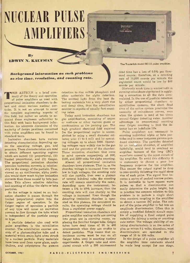
THIS ARTICLE is a brief sum- mary of the theory and operation of pulse amplifiers as used with
proportional ionization chambers to de- tect and count various nuclear par - ticks. It is not an attempt to cover the complete engineering aspects of this field, but rather an article to ac- quaint those engineers unfamiliar to this field with basic background infor- mation. An adequate discussion of the majority of design problems concerned with pulse amplifiers can be found in standard texts.
Ionization chambers have various detecting characteristics depending up- on the operating voltage, gas, and pressure. These characteristics are used to obtain different operating regions which are named (1) proportional, (2) limited proportional, and (3) Geiger. The proportional ionization chamber provides ionization currents in relation- ship to the energy of the particle. Thus, viewed on an oscilloscope, alpha parti- cles'would show much higher ionization currents than those caused by beta par- ticles. This allows selective detection and counting of either the alpha or beta particles.
As the voltage is raised on an ioni- zation chamber it passes through the limited proportional region into the Geiger region of operation. In the Geiger region of operation a particle of any type will cause an ionization current to flow through the tube which is independent of the particle energy or type.
A particle detector also used with pulse amplifiers is the scintillation counter. The scintillation counter con- sists of a photomultiplier tube and a material which emits light when struck by a nuclear particle. Many materials have been used from vycor glass, naph- thalene, and polystyrene for gamma
detection to zinc sulfide phosphors and other materials for alpha detection. The emitted light from the best de- tecting materials has a very short rise and decay time, thus the scintillation counter is capable of usually fast count- ing rates.
Today most ionization chambers use gas amplification, consisting of argon or methane or other various gases or combinations as the ionizing gas. The high gradient electrical field required for the proportional region is accom- plished by using a small diameter col- lector wire (1 to 3 mil) and by operat- ing voltages up to about 5000. Operat- ing voltages vary widely due to the gas used and the geometry of the chamber. Three ionization chambers that come to mind operate respectively at 900, 2100, and 3300 volts for alpha counting.
Almost all proportional ionization chambers have plateaus. That is, as the chamber voltage is increased from very low to high voltages, the counting rate will rise rapidly, then over a plateau of several hundred volts the counting rate will remain essentially the same; depending upon the instrument, be- tween a 1% to 20% increase; then the counting rate will rise sharply as the voltage is increased. Even though the detecting ionization chamber is oper- ated on this plateau, for consistent re- sults, the operating voltage should be from a regulated power supply.
Proportional ionization chambers and pulse amplifier scaling units are coming into great use in counting rooms, re- placing the familiar Geiger tube. Geiger tubes have dead times of 90 to 400 microseconds when they are unable to detect particles. This means that co- incidence curves must be run on all Geiger tubes used in exacting nuclear experiments. A Geiger tube and asso- ciated circuit with a 300 microsecond
¡rci .(L6 ' PULSE AMPLIFIER
The Tracerlab model SC -15 pulse amplifier.
dead time has a loss of 0.5% per thou- sand counts; therefore, at a counting rate of 10,000 counts per minute the registered count would be low by 500 counts per minute.
Obviously much time is wasted both in running coincidence cheas andin apply- ing a correction to all the data accu- mulated. In the use of çarticle detection by either proportional chambers or scintillation systems, the short dead time of the entire system precludes the necessity of coincidence curves, even where the system is used at ten times normal Geiger detecting rates. Another advantage to proportional counting over Geiger counting is that the de- tector has an indefinite life.
Pulse amplifiers are necessary in counting individual alpha or beta par- ticles and in some instances gamma -pro- duced electrons. The particles detected by an ionization chamber, if amplified faithfully, would tend to overload an amplifier because of the long (RC) waveform caused by the input circuit of the amplifier. To avoid this difficulty it is customary to choose a poor low frequency response for the amplifier. This causes the output signal to drop to zero quickly following the rapid steep rise of each pulse. The signal thus be- comes a series of peaked narrow pulses. It is desirable to have square wave pulses so that a discriminator can easily determine the pulse height, but in practice the common solution to this problem is to include a single short time constant coupling in the amplifier to obtain a narrow RC pulse. The out- put of the pulse amplifier is fed into an amplitude discriminator. Often this is simply a modified Schmitt circuit capa-' ble of supplying a fixed output pulse suitable for driving a scaler or counting rate meter. The voltage stability of ex- isting discriminators is on the order of plus or minus 0.1 volts; therefore, most discriminators are operated in tlïe range of 10 to 100 volts.
In the design of a pulse amplifier all the amplifier time constants should be made long except for one stage,
OCTOBER, 1951 R A D I O- E L E C T R O N I C ENGINEERING 7

which should have the short time con- stant. This raises the question of where to place the short time constant. From one standpoint the coupling should be placed at a point where there is no danger of preceding stages overloading from the pile-up of pulses. From an- other standpoint, it should be placed as far along in the amplifier as pos- sible, since it acts as a filter for hum, microphonics, and low frequency noise components originating in early stages.
Generally the Short time constant coupling is placed at the input to the main pulse amplifier which has been preceded by one to four tubes of pre - amplification. This type of pulse shap- ing has certain disadvantages so that some amplifiers are being built with delay line pulse shaping to provide a square wave pulse. Complexities, how- ever, have limited this method.
A discussion of pulse amplifiers would not be complete without a men- tion of regulated power supplies. The power supply used with a pulse ampli- fier is fully as important as the ampli- fier itself. The use of gaseous voltage regulator tubes has no place in a pulse amplifier power supply except as a reference source.
This can be a sad fact unknown for weeks while experimentation goes on. A vacuum tube regulator system must be used, one with a high degree of stability and gain and low impedance. If this is not used, amplifier oscillation and pulsing will occur even though heroic steps are taken to decouple the amplifier stages.
Noise is the big problem of pulse amplifiers. Pulse amplifiers whose low frequency response has been reduced
800
700 Z
600 m w a
Ú 500 (n
a 2 400V o z 300
8 0 200
m I00
for the purpose of shaping pulses from an electrical detector are naturally less sensitive to hum and microphonic pick- up. These amplifiers often use a com- mon a.c. heater supply for all stages. The main cause of spurious counting is power line transients that have high frequency components. To minimize these transients one of the following remedies may be used: an electro- static shield on the filament trans- former; an isolation transformer for the entire unit; or running the instru- ment from an instrument a.c. line where no electrical machinery is connected at all. A prime example of the cause of this type of transient is the office cal- culating machine.
Noise is also picked up electromag- netically. This is a serious type of noise as it is very difficult to eliminate. One main cause is the multiplicity of grounds often used. It is often difficult or impossible to use a minimum of grounds. In general, the best advice that can be offered is to choose an elec- trically quiet room or building while carrying out experiments.
Signal-to-noise ratio can often be in- creased considerably by using a triode preamplifier input tube instead of a pentode tube such as has been used in the past years.
The above -mentioned causes are the usual noise sources; however, few texts mention power supply pulse noise cre- ated by insulation leakage from the ionization chamber high voltage supply. This is often the main cause of spurious counting. This can be easily seen. The power supply feeds the bottom of the chamber collector resistor. The signal caused by alpha or beta pickup pro -
Fig. 1. Typical pulse amplifier gain and discriminator settings for photoneutron counting. Chamber voltage, 600 v. Operating gain 1-50.
7,000
6,000
5,000
4,000
3,000
2,000
GAIN I-50
GAIN I - MAX.
N . s
GAIN -0
GAIN
10 20 30 40 DISCRIMINATOR
50
I-0 leKGR4UND
60 70
duces a voltage drop across this 're- sistor, which in turn is fed into the grid of the preamplifier input tube. Generally, at low voltages (1000 or under) no leakage trouble occurs.
In many cases ionization chamber voltages range upward to 5000 volts. A few electrons leaking to ground from either the top or bottom of this input resistor in a spurious fashion will in- troduce a signal into the amplifier exactly as if the ionization chamber had collected electrons due to ioni- zation. The same effect occurs when the high voltage lead intermittently breaks down to ground, invisible to any high voltage meter due to the low current drain of a few electrons.
The same effect of spurious counting will happen if corona occurs, almost anywhere, in the high voltage power supply. Sometimes this corona is hard to detect as it is so slight. Naturally all precautions should be taken, such as large rounded surfaces where high voltages are concerned.
Generally the high voltage leads and input resistor to the ionization chamber are supported on stand-off or feed - through insulators.
Only the ceramic insulators, such as Steatite, under -rated by a factor of three to eight, are satisfactory for this use. Bakelite and other stand-offs have severe leakage at high voltages. Some designers have a low -capacity condens- er mounted directly at the ionization chamber, at the bottom of the input re- sistor to eliminate pulses originating in the high voltage lead and power supply, but this is certainly not a cure- all. Lucite and polystyrene are poor stand-off materials as they generate pulses from mechanical strains. This has been covered in various papers. Polystyrene can be used but it is diffi- cult to work with and maintain the clean surface that is so necessary. All in all, the two best stand-offs, feed -through, or supports are either ceramic material or glass beads such as are usgd in hermetically -sealed transformers. In some instances it is possible to clip down the high voltage lead, usually an RG cable, so that it can act as the stand-off itself. The. fewer stand-offs the less trouble will be encountered.
Cable connectors can also cause spur- ious pulses. Several companies make special pulse -type connectors. In gen- eral these connectors are not necessary except in areas of high humidity or where voltages over 3000 are expected to be used.
The preamplifier input resistor can be of a standard type even though high voltage is impressed across it as the actual voltage drop across the resistor is very small.
The input high voltage coupling con- denser is very critical. The best con -
8 RADI O -ELECTRON I C ENGINEERING OCTOBER, 1951

dens, found so far for this use is the Germzkab 850 series. These condensers are direly satisfactory where the hu - midi is 60% or under. Power supply and lulse decoupling condensers are also ztremely critical. The most satis- fact.y condensers from an internal and xternal leakage and pulse gener- ation consideration are Glassmikes.
TI "Bible" for pulse suppression is an a;icle by F. M. Glass in the April 1949eview of Scientific Instruments.
T} gain of a pulse amplifier as used in decting particles is usually on the jrde of 10° although gains of 105 have enised and even 100 times smaller
cvhei gas amplification is used in the a cal detector. It is usual to have
naximum amplifier gain large -non to make the random noisé out-
put o less than 10 volts as the dis- çrimrators in use are not used below 10 Nits. Almost all pulse amplifiers 1,;...coarse and fine gain controls. The
gain control is a step attenuator s ting of a simple resistor network.
I Ile ne gain control is a potentiom- -.rhe output pulses from a pulse II ìer are usually chosen to have
Live polarity so that a low im- -e cathode follower output stage
a :able. The output of the cathode ICI oer goes through a cable to a dis -
r ator stage mounted in a scaler. i.:r version, and in my opinion,
mr: 2 superior, has the discriminator st a mounted on the pulse amplifier ch: s t. This permits the pulse ampli - f id discriminator to be used with
any scaler. amount of gain stability of a
p.I 13, Implifier becomes very important whin -the electrical detector does not n 3 a good plateau. Thus, for best
an amplifier should have quite f feedback.
'I high frequency response of a pu I s, amplifier is usually expressed in
r in of amplifier rise time. Rise times rangbetween 0.05 and 10 microseconds, .1c l,e ling upon the experiment. This
I P. of rise times corresponds to a ig of upper half -power frequencies
rim mc. to 300 kc. If the pulse amp- li tier 's driving a scaler with a ten micrnecond resolution, then having a tise -ne much shorter than 10 micro-
cor3 would be useless. As one may &nil; calculate, the counting rate at rw,,n en microseconds is quite high, but slier units are being designed with It) j I higher resolution time for use with hort-lived radio isotopes which have igh particle rates over a period of secor,s to minutes.
In perating a pulse amplifier and ibniz ion chamber the chamber voltage an,l a amplifier gain and discrimina - 61r net be adjusted to give a minimum tiny; ted background, as well as to lo, at. a plateau with the best slope.
Top view of the Tracerlab pulse amplifier, showing placement of parts.
This generally is done by setting a fixed chamber voltage and setting the amplifier gain to a fixed value. The discriminator is then varied between 10 and 100 volts and the counts per minute recorded at the various discrimi- nator settings. The procedure is re- peated, maintaining the fixed gain, raising the chamber voltage to a new fixed voltage, and varying the discrim- inator and again recording the counts per minute at the various settings. Finally, the gain is increased and an- other set of curves obtained. This re- quires a good deal of time and a large number of curves to be drawn. For- tunately, the operating voltage of many chambers is known so that the proce- dure is simplified; the chamber voltage is fixed, and curves run with various amplifier gains and discriminator set- tings. If a serious background exists, such as unwanted gamma, these curves will indicate the settings to stay under for a minimum background count. Fol- lowing these tests a radioactive sample is inserted in the detecting chamber and all the above repeated. An examination of the curves obtained will obviously give the best operating position.
The detection of neutrons imposes special problems. Slow neutrons are, as a rule, detected by boron lined or boron gas filled ionization chambers. The neutron upon striking the boron produces an alpha particle which ion- izes the gas present in the ionization chamber. Fast neutrons are slowed up by a moderator such as polyethylene and then detected.
In some instances "fission cham- bers" are used to detect slow neutrons; although the output pulse is extremely strong, the counting or detecting effi- ciency is very low. The fission chamber
does have the advantage that it will not detect gamma and therefore has no gamma background which must be dis- criminated against.
A fission chamber consists of a piece of enriched uranium or other fission- able material and a fine collector wire. A neutron striking the uranium causes fission to take place. The fission pro- ducts are then detected. As can be seen, a "fission chamber" can be used to detect neutrons only.
The curves included with this ar- ticle are typ ^al examples of a pulse amplifier system, used with a boron lined ionization chamber, to detect neutrons. The neutrons in this case were produced by subjecting beryllium blocks to gamma rays. The photographs of the pulse amplifier show typical con- struction methods and electrical parts layout.
Fig. 2 Typical curve of pulse amplifier and discriminator settings to lower background gamma count when count- ing neutrons with boron lined ionization chamber. Photoneutrons are produced by radium gamma rays on beryllium.
90,000
35,000
30,000
25,000
20,000
15,000
10,000
5,000
0
NEUTRON COUNTING REGION
NEUTRONS GAMMA ONLY
0 40 50 60 70 80 90100 DISCRIMINATOR
OCTO,R, 1951 RADIO -ELECTRONIC ENGINEERING 9

GATE And DELAY
GENERATOR
By ROBERT R. RATHBONE
Servomechanisms Laboratory Massachusetts Institute of Technology
This unit provides a rectangular gate variable from 0.5 to 2500 microsec., and a 0.1 microsecond pulse.
IN GENERAL, the gate and delay generator is used to "open" and "close" gate tubes at specified
times and to trigger flip-flops at the end of a given delay. It provides a rectangular pulse, or gate, and a de- layed 0.1 microsecond, half -sine -wave pulse. The length of the gate is con- tinuously variable from 0.5 to 2500 microseconds; the 0.1 microsecond pulse is coincident with the end of the gate. The two outputs may be used simul- taneously or separately.
Since many test setups require more than one gate -and -delay building block, two identical, independent generators were constructed side by side on a single
Fig. 2. Clamping circuits and wave- forms for gate outputs. (A) Clamping to positive portion of gate. (B) Clamp- ing to base line of the clipped gate.
chassis. (This feature not only saves installation time and rack and storage space, but also is extremely convenient when one section is used to feed the
second.) Fig. 1 shows the two sections separated by a shield. All controls and jacks required for normal operation are on the front panel; the vacuum tubes and power cable plug into the rear. 0 -ver -all rack space required: 6 x 19 inches; depth with plug-in components mounted: 10 inches.
A power supply has not been built into the unit since all the new M.I.T. test blocks operate from central labora- tory supplies. The power requirements for operation of both sections at the same time under no signal and 4 kc. signal conditions are:
Voltages Currents No Signal 4 kc. Signal
+250 v.d.c. 115 ma. 110 ma. +150 v.d.c. 220 ma. 195 ma. -150 v.d.c. 8.5 ma. 8.5 ma.
6.3 v.a.c. 7.55 amp. 7.55 amp. The resolution time of the gate gen-
erator varies with the "coarse delay" setting. For the 10 µsec. setting, the resolution time is 1 µsec.; for the 50 µsec., 2 µsec.; for the 450 µsec., 10 µsec. ; and for the 2500 µsec. setting, 70 µsec. These resolution times are min- imum for reliable operation.
A 0.1 microsecond positive pulse is fed into either input jack J1 or .12 (Fig. 5). The input line may be either ter -
Fig. 1. Top -front view of the MIT duplex gate and delay generator.
minated or not, by switching R,, the 93 ohm terminating resistor, in or out by means of S,. The pulse is then capac- itor -coupled to the grid of the trigger tube, V.. This tube is normally biased beyond cut-off, and is made to conduct by the pulse. Plate current then flows through R9, the plate load resistor of V,A, which is the normally -off section of the single -shot multivibrator. The negative -voltage pulse which results is coupled through either C6, Cr, C,, or C., depending on the position of the "coarse delay" switch, to the grid of V25, which is the normally -on section of the single - shot multivibrator. This triode ampli- fies the negative pulse and the resulting positive pulse is fed back to the grid of V2A, triggering the multivibrator to its other state. The pertinent voltage waveforms may be seen in Fig. 3, a through d.
Fig. 3e shows the voltage at the grid of V2s, the normally -on section. The waveform shows how the coupling ca- pacitor loses its charge during the de- lay interval, until the grid comes into the conducting region and the circuit triggers back to its stable state. The length of the delay interval depends on the rate at which this capacitor (C,, C,, Cs, or C.) loses its charge; that
Editor's Note: The test equipment units sponsored by the Office of Naval Research and developed during the past three years by the M.I.T. Servomechanisms Laboratory were designed as building blocks to teat pulsed circuits and simulate the control, arithmetic, and storage functions of an elec- tronic digital computer. Two of the blocks, the Variable -Frequency Clock -Pulse Gener- ator and the Pulse Mixer, have been de- scribed in previous issues of RAnro-ELEC- TRONIC ENGINEERING. A third and extremely useful block, the Gate and Delay Generator, is described in this article.
Credit for the original design of the Clock and the Gate and Delay Generator goes to Harry Kenosian, now with the Burroughs Adding Machine Co. Chester A. Rowland, now with Engineering Research Associates, designed the Pulse Mixer.
10 RADIO -ELECTRONIC ENGINEERING OCTOBER, 1951

i
is, the delay interval depends on the time constant of the grid circuit. The "coarse delay" switch selects different coupling capacitors to give coarse con- trol over the delay range, while the "fine delay" potentiometer R12, gives fine control over the time constant, and hence the delay.
When the circuit triggers back to its stable state, the grid of V28 goes.
slightly positive as the coupling capac- itor is recharged through the grid -to -
cathode diode action of V2». While the grid of V 21 is positive, the tube con-
ducts more heavily, causing the nega- tive overshoot seen in the plate wave- form of Fig. 3d. .
Any fluctuations in the positive sup- ply voltage would cause equivalent changes in the initial charge on the coupling capacitor, which in turn would cause variations in the delay interval. Fluctuations in both the positive and negative supply voltages would change the quiescent bias on V2A, and could make the circuit either difficult to trig- ger or dangeroúsly close to free run- ning. These same fluctuations could vary the amount of grid current drawn by V2a during the delay interval, and therefore vary the plate swing of V32
and hence the delay interval propor- tionately. For all of the above reasons, voltage -regulator tubes were used to isolate the circuit from supply fluctua- tions. VG drops the +250 volt supply down to +150, and V, drops the -150 volt supply to -105 volts.
Cathode Follower The positive gate that appears at
the plate of V28 (see Fig. 3d) is capac- itor -coupled to the grid of the cathode follower, V3. The cathode follower drives the "gate output" jack J3 (Fig.
(0) INPUT PULSE
(b) PLATE OF V2A
(C) GRID OF V2B
(d) PLATE OF V20
(e) GATE OUTPUT
(f) CLIPPED -GATE OUTPUT
DELAY INTERVAL-7)JSeC SWEEP SPEED-Spsec/IN.
Fig. 3. Pulse shapes of gate generator.
3e). Since the gate is a.c. coupled to the cathode follower, the d.c. level of the base line will depend on the duty factor. It was intended that this gate would be a.c. coupled to some exterior circuit, so that this change in d.c. level was not considered objectionable, and the gate works very well if the new d.c. level in the exterior circuit is estab- lished by clamping to the positive por- tion -of the waveform, as shown in Fig. 2A. If it is desired to clamp to the negative portion, or to the base line, then the overshoot at the end of the gate becomes very objectionable. For this reason, the "clipped gate" output was provided. R23 and germanium diode
(0) CLIPPED -GATE OUTPUT
(b) PULSES GENERA- TED BY LEADING AND TRAILING EDGES OF GATE
(PLATE V3) (C) PULSE GENERATED
BY TRAILING EDGE
OF GATE ON
FASTER SWEEP (PLATE V3)
(d) LEFT-HAND PLATE
OF V4
(e) GRID OF V5
(f) PULSE OUTPUT
DELAY INTERVAL -7psec SWEEP SPEED- 5j15eC/IN. FOR O AND b, AND ipsec/IN. FOR C THROUGH f.
Fig. 4. Pulses of delayed -pulse generator.
CR2 clip the overshoot, and provide a base line with no overshoot, suitable for clamping (see Fig. 2B). The "clip- per control," R26, varies the amount of clipping. Since the gate is a.c. coupled to the grid of the cathode follower, the d.c. level of the base line varies with the duty factor, making a "clipper con- trol" neçessary. The clipped gate may be seen in Fig. 3f.
The cathode follower has an R -L -C peaker in its plate, the waveform of which may be seen in Fig. 4b. (The clipped gate is shown in Fig. 4a to give a time r,ference.) Diode CR, damps out any negative ringing of the peaker when the follower conducts at the be- ginning of the delay interval. At the end of the delay interval, the peaker
(Continued on page 24)
JI
2
RIO
m,y,
93
SI
6AK5
:R3 :
LO1
±5%
R9
C5 4K 22VVIJ.
LI 2SVHY.
'`RII 3.30
3zw.ÁÑ = p6a
IM R12 +.7K
+6% R13
01
47 zw.
2.2 K 2W.
.0033 ,C6
COARSE DELAY
500K
FINE DELAY
50P 1!.
C.
VR150
12.1
470 Vu Q C]
430 100
V9EC.
e
EC9-!0 SEC.
C9 - 20V EC.
( MULTIVIBRATOR(
10
GIL 4,192 R16 47 ¶ - .D
CATH00E FOLLOhER
.01
115
40
J3 J+
-o 0'44 GATE
OUTPUT
OO - R29
R26 ' 820 2W
IW.
1- tre 3R] 69864 ¡690 K
>R24 fQK
CR2 $ 1539
28 R22 17
C16 725 0.25
CLPPE0 GATE
C IPPER CONTROL
Fig. S. Schematic of gate and delay generator
PULSE GENERATOR
X3/ p.23N 1BA
2
R3 ó J :ä C91
C2.13 1 C201 Ñ'3q + li .25 o.25 2.5
6A'
RS»
PULSE 4NP-
LI UVE
0
220 CR
T1 0-359 3:1
PULS
PULSE OUTPUT
C2I --.01
PULSE
150V AMP IFlER
10
NIR. +150V. 6.3V.
+ 250V.
OCTOBER, 1951 RADIO -ELECTRONIC ENGINEERING 11
The Series
AMPLIFIER By
EDWARD L. CROSBY, JR. Bendix Radio Division
MAGINE a television i.f. strip of four stages just barely larger than a penny box of matches !-or a ra-
dar receiver, less local oscillator and plumbing, which may be held in the palm of your hand!-or a communica- tions receiver i.f. and detector assem- bly which will operate reliably at the temperature of boiling water and which will withstand shock acceleration of 100 G's! These and other interesting developments are possible with a new amplifier technique developed at the Research and Development Laborato- ries of Bendix Radio Division. The se- cret of this technique does not depend on printed circuits or other component subminiaturization. Rather, in the cir- cuit design, most of the components have been left out.
Let us briefly consider the history of this new approach. For the past several years, a great deal of engineering effort has been expended in the field of sub - miniaturization, the art of making elec- tronic equipment as small as possible. This trend began in earnest when sub- miniature tubes of the heater -cathode type became available for a.c. service. It progressed to the point where conven- tional components had been reduced in size until they were expensive, fragile and very difficult to assemble. At this point, progress ceased, until high -K ceramic dielectrics, ceramic tinning techniques, and printed circuit methods were developed. These new tools gave subminiature circuit development a push, and again great strides were made in equipment size reduction. Dif- ficulties appeared however, such as the instability and inaccuracy of printed resistors, necessity of special (and ex- pensive) assembly methods, difficulty of repair, and the fundamental impos- sibility of printing inductors of large values. It was at this stage that the series amplifier technique was born.
In order to approach the problem from a completely fresh viewpoint, the Bendix people chose a type of unit which badly needed reliable subminia- turization, the high -frequency, high - gain, wide -band i.f. amplifier.
To follow the reasoning used, con -
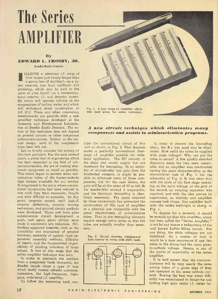
Fig. 1. A four stage 1.f. amplifier which was built using the series technique.
A new circuit technique which eliminates many components and assists in miniaturization programs.
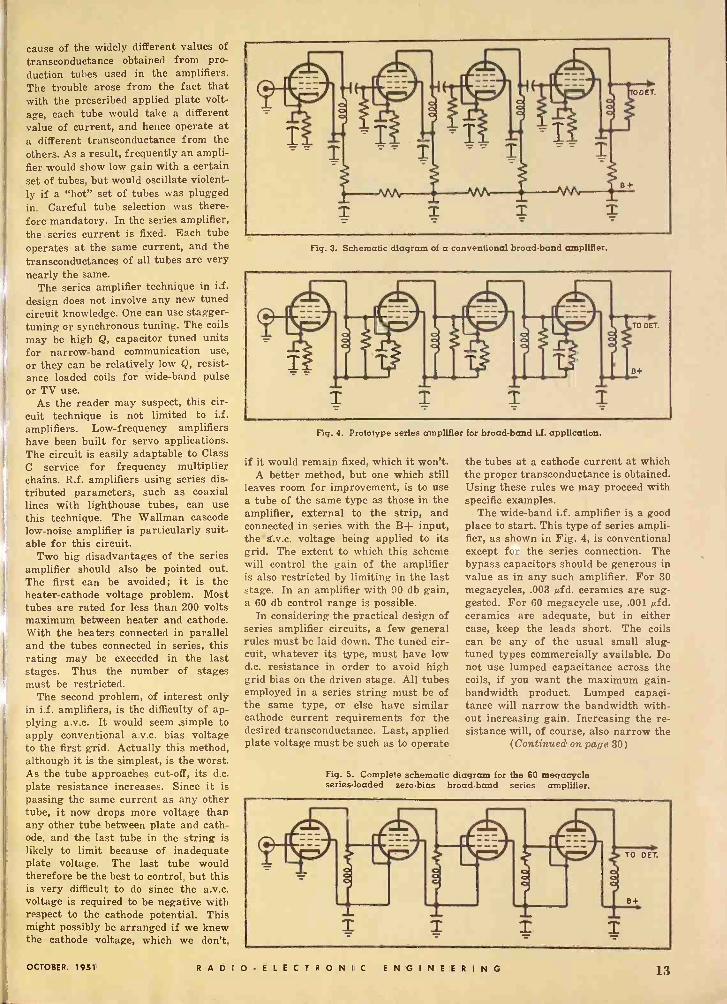
sider the conventional circuit of this unit as shown in Fig. 3. This diagram shows a perfectly conventional four - stage i.f. amplifier suitable for wide - band application. The RC circuits in the plate and screen supply bus are necessary for decoupling. In an ampli- fier of considerably less gain than the illustrated example, it might be pos- sible to eliminate some of these com- ponents, but for the case shown, the gain will be of the order of 80 to 100 db for bandwidths around 3 megacycles, and the thorough decoupling is abso- lutely necessary. The space required by these components has prevented the construction of this type of amplifier in a physical size compatible with the space requirements of subminiature tubes. That is, the decoupling elements require enough extra space so that the tubes are actually smaller than neces- sary.
Fig. 2. Circuit showing unbypassed bias resistor in series with plate load.
In order to remove the decoupling chain, the B+ bus must also be elimi- nated. How could the tubes be supplied with plate voltage? Why not put the tubes in series? A few quickly sketched diagrams made the idea seem reason- able, and an amplifier was constructed having the same characteristics as the conventional unit of Fig. 3 but the schematic of Fig. 4. It was clear that with the plate of the first stage operat- ing at the same voltage as the grid of the second, no coupling capacitor was required, and with the idea proven by experiment, an entirely new amplifier concept took shape. One amplifier built with the series technique is shown in Fig. 1.
To digress for a moment, it should be pointed out that this amplifier, which has been called the "Series Amplifier," is not by any means a rediscovery of the well known Loftin -White circuit. For one thing, the plate voltages are not stabilized. As a matter of fact, it would be a rare occurrence if any two tubes in the string had the same plate - to -cathode voltage. Herein is one of the points of superiority of the series amplifier.
It is well known that the transcon- ductance will be very nearly the same among tubes of a given type if they are operated at the same cathode cur- rent. During the last war great diffi- culty was experienced in designing and testing high gain radar i.f. strips be -
12 RADIO -ELECTRONIC E N G I N E E R I N G OCTOBER, 1951
cause of the widely different values of
transconductance obtained from pro- duction tubes used in the amplifiers. The trouble arose from the fact that with the prescribed applied plate volt- age, each tube would take a different value of current, and hence operate at a different transconductance from the others. As a result, frequently an ampli- fier would show low gain with a certain set of tubes, but would oscillate violent- ly if a "hot" set of tubes was plugged in. Careful tube selection was there- fore mandatory. In the series amplifier, the series current is fixed. Each tube operates at the same current, and the transconductances of all tubes are very nearly the same.
The series amplifier technique in i.f. design does not involve any new tuned circuit knowledge. One can use stagger - tuning or synchronous tuning. The coils may be high Q, capacitor tuned units for narrow -band communication use, or they can be relatively low Q, resist- ance loaded coils for wide -band pulse or TV use.
As the reader may suspect, this cir- cuit technique is not limited to i.f. amplifiers. Low -frequency amplifiers have been built for servo applications. The circuit is easily adaptable to Class C service for frequency multiplier chains. R.f. amplifiers using series dis- tributed parameters, such as coaxial lines with lighthouse tubes, can use this technique. The Walluran cascode low -noise amplifier is particularly suit- able for this circuit.
Two big disadvantages of the series amplifier should also be pointed out. The first can be avoided; it is the heater -cathode voltage problem. Most tubes are rated for less than 200 volts maximum between heater and cathode. With the heaters connected in parallel and the tubes connected in series, this rating may be exceeded in the last stages. Thus the number of stages must be restricted.
The second problem, of interest only in i.f. amplifiers, is the difficulty of ap- plying a.v.c. It would seem .simple to apply conventional a.v.c. bias voltage to the first grid. Actually this method, although it is the simplest, is the worst. As the tube approaches cut-off, its d.c. plate resistance increases. Since it is passing the same current as any other tube, it now drops more voltage than any other tube between plate and cath- ode, and the last tube in the string is likely to limit because of inadequate plate voltage. The last tube would therefore be the best to control, but this is very difficult to do since the a.v.c. voltage is required to be negative with respect to the cathode potential. This might possibly be arranged if we knew the cathode voltage, which we don't,
Fig. 3. Schematic diagram of a conventional broadband amplifier.
Fig. 4. Prototype series amplifier for broad -band id. application.
if it would remain fixed, which it won't. A better method, but one which still
leaves room for improvement, is to use a tube of the same type as those in the amplifier, external to the strip, and connected in series with the B+ input, the-á.v.c. voltage being applied to its grid. The extent to which this scheme will control the gain of the amplifier is also restricted by limiting in the last stage. In an amplifier with 90 db gain, a 60 db control range is possible.
In considering the practical design of series amplifier circuits, a few general rules must be laid down. The tuned cir- cuit, whatever its type, must have low d.c. resistance in order to avoid high grid bias on the driven stage. All tubes employed in a series string must be of the same type, or else have similar cathode current requirements for the desired transconductance. Last, applied plate voltage must be such as to operate
the tubes at a cathode current at which the proper transconductance is obtained. Using these rules we may proceed with specific examples.
The wide -band i.f. amplifier is a good place to start. This type of series ampli- fier, as shown in Fig. 4, is conventional except fc: the series connection. The bypass capacitors should be generous in value as in any such amplifier. For 30 megacycles, .003 µfd. ceramics are sug- gested. For 60 megacycle use, .001 µfd. ceramics are adequate, but in either case, keep the leads short. The coils can be any of the usual small slug - tuned types commercially available. Do not use lumped capacitance across the coils, if you want the maximum gain - bandwidth product. Lumped capaci- tance will narrow the bandwidth with- out increasing gain. Increasing the re- sistance will, of course, also narrow the
(Continued on page 30)
Fig. 5. Complete schematic diagram for the 60 megacycle series -loaded zero -bias broad -band series amplifier.
OCTOBER. 1951 RADIO -ELECTRONIC ENGINEERING 13
An Introduction To
COMPUTER
CONCEPTS By
JOHN D. GOODELL The Minnesota Electronics Corp.
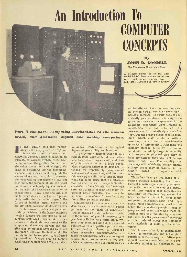
A problem being run on the older model REAC. Two cabinets at left are servo and power supply, two at right dre computer and power supply.
Part 3 compares computing mechanisms to the human 1rain, and discusses digital and aalog computers.
T HAS BEEN said that "proba- bility is the very guide of life," and it is certainly true that every man
continually makes decisions based on his estimate of various probabilities. Such decisions are: the guiding factor in en- gineering invention and design; the basis of reasoning for the technician, the means by which executives guide the course of corporations; for statesmen, the progress of government; and for each man, the manner of his life. Most decisions made hourly by everyone do not warrant the precise computation of probabilities. Many decisions are also made every day on the basis of proba- bility estimates on which depend the future of families, cities, nations and society. Such decisions do deserve every effort to insure precise computation.
Many decisions in the latter category involve factors too complex to be ac- curately estimated in the mind. In such instances individuals may resort to the supplemental memory storage and par- allel display methods affqrded by pencil and paper. But even the best mind, ulti- mately limited by complexity, is affected by emotional factors and no human reasoning structure will always produce
an answer conforming to the highest degree of probability confirmation.
It is a common concept that the only fundamental capability of computing machines is that they can add, and their only important value is high speed. Most machines designed to date are in- tended for repetitively programmed mathematical operations, and for them this concept is valid. It is true in some- what the same sense that all informa- tion may be reduced to a symbolization consisting of combinations of one and zero. But there is at least one other im- portant basic operation that may be built into a machine. It can be given the ability to make guesses.
Guesses may be made on a sheer ran- dom basis, in accordance with preset patterns, on the basis of experience (which implies the ability to learn), etc. If the number of possible answers to a problem is limited to a finite set, a sys- tem that examines all the answers at random or in a repetitive pattern may be satisfactory. Speed is improved when successive approximations are made in accordance with a convergent series. When convergence is not pos- sible and answers must be considered as
an infinite set, then no machine (and no human being) can ever consider all possible answers. The only hope of con- sistently good solutions is to weight the guessing process with experience. If the available experience were limited to association with . one individual this process would be relatively unsatisfac- tory, but the shared experience of man- kind (which may be shared with a machine) constitutes a considerable quantity of information. Although the memory storage banks of the human mind are incredibly large in capacity with respect to physical size, they do have limitations that need not be ap- plied to machines. The rapidity and accuracy with which the human mental storage banks may be scanned is dis- tinctly limited by comparison with machines.
There has been an avalanche of in- tuitive guesses regarding the limita- tions of machine operations by compari- son with the operations of the human mind. Any concept that indicates the possibility of complete duplication has been rejected as naive by most really competent mathematicians and logi- cians. Most rejections are based on the belief that machine operation must be programmed repetitively and most ob- jections may be eliminated by a system that includes the processes of guessing on the basis of experience combined with methods of making randomized jumps.
The human mind is a continuously operating mechanism, and although it functions rather slowly, a lifetime per- mits the random consideration of a con- siderable number of hypotheses. Ac -
14 RADIO -ELECTRONIC E N G I NEE R I N G OCTOBER, 1951
i
f
i
tually the notion of creative thinking is linked with such random operations and with the ability to recognize a good guess when it comes along. The crea- tion of machines capable of duplicating or improving on the functions of the human mind does not necessarily imply the arrival of any kind of millenium, neither does it imply any necessary dis- aster. It will not eliminate emotional conflicts or resolve the problems of human relations. It may accelerate the process that is currently conceived to be "progress" and it may minimize errors in judgment that lead to painful mistakes.
It is important to recognize that no degree of confirmation of a probability implies certain prediction. The best guess is the one that has the highest degree of confirmation at the time it is made and this is not affected in any way by the ultimate answer. Uncertainty is
not eliminated by making the best pos- sible guess.
The human mind is an extremely flex- ible general purpose instrument, ca- pable of performing an endless variety of computations. This is one of its most remarkable characteristics and at the same time one of its most limiting fea- tures. It is almost axiomatic that gen- eral purpose flexibility involves com- promises, and one of the great ad- vantages of machines is the fact that they may be designed for specialized applications.
In applications where it is necessary to resolve a large number of variables with maximum speed, continuously self- adjusting mechanical linkages of the analog variety are indicated. In most applications the digital type of com- puter has certain advantages. One of these is the fact that the error is a definite and predictable quantity that will be constant for all similarly con- structed machines. With mechanical linkages the error is a function of the precision with which the parts are made and linked together. There are nb two alike. With the digital machine the error will remain the same for the life of the machine while with the analog mechanical variety it will accumulate with wear and usage. Maintenance of digital computers requires only moder- ate technical skill, while the mainte- nance of mechanical analog machines involves the services of very highly trained personnel.
Continuously self-adjusting linkages, of course, are not the only form of analog device and many problems may best be solved by manipulating infor- mation in terms of electrically analo- gous signals. Such systems are usually capable of greater speed than digital machines; in general they do not change with time and use as greatly as me- chanical linkages, and they undoubt-
edly have an important and permanent place in future machine developments. Many designs will probably use com- binations of analog and digital presen- tations, particularly when convenient and rapid translating systems have been fully developed.
Any device, contemplated for widé use in digital computers, that is not capable of handling information at pulse repetition rates of a megacycle or higher is considered seriously limited. This means that the advantage of es- sentially instantaneous tracking now held by analog devices may become of little consequence in the not too distant future.
Neglecting input and output struc- tures, a digital computer consists of computing elements, memory storage banks, and internal program control systems. One of the important decisions in the design of such machines is the compromise that must be made between the number of computing elements, the dimensions of the storage banks, and internal program control complexity. Most operations are performed repeti- tively and it is not efficient to include duplicate circuits for the same oper- ation. In order to avoid this the infor- mation is fed into temporary storage and re -cycled through a single comput- ing section in accordance with the in- structions supplied by the program con- trol circuitry. Speed becomes more seriously limited by the characteristics of the control circuits and the storage and access time of the memory banks than -the computing elements. In most medium and large scale computers the memory elements are the largest sec- tions of the machine both from the standpoint of physical dimensions and number of components.
The importance of program control systems emphasizes the need for com- pact coding of instructions. While it is
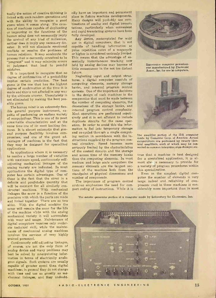
Sine -cosine computer potentiom- eter manufactured by Electronic Assoc., Inc. for use in computers.
The amplifier portion of the IDA computer made by Computer Corp. of America. Actual computations are performed by twenty iden- tical amplifiers, each of which may be con- nected as summer, integrator, sign -changer, etc.
true that a machine is best designed for a specialized application, it is al- most alw ;fs necessary to provide for a variety of program procedures within this specialization.
Even in the simplest digital com- puter the number of elements is very large indeed and reliability of com- ponents used in these machines is con- siderably more important than in most
The master generator portion of a computer made by Laboratory for Electronics, Inc.
OCTOBER, 1951 RADIO -ELECTRONIC ENGINEERING 15

The MADDIDA, made by Northrop `ircraft, Inc. This production model was designed and ,built for the experimental towing tank of Stevens Institute of Technology. It can be operated by one person, and gives its answer in columns of figures or as plotted curves.
types of equipment. The character of the tasks assigned to them is often of such importance that break-down or error may result in serious conse- quences. As a result of this and also considerations of simplification and miniaturization there is a continual effort to find components that may be used instead of electron tubes. At the present time various types of storage elements have almost completely re- placed tubes for purposes of memory. Included are magnetic drums, magnetic tapes, magnetic cores, mercury delay
lines and many others, some of which have not yet been publicized. Magnetic amplifiers and other systems of amplifi- cation are rapidly increasing in impor- tance. Gates, oscillators, counters and practically every circuit element in a computing machine may be designed without the use of tubes. This does not necessarily mean that tubes will be com- pletely eliminated, but it could happen and perhaps it will. If so, it will un- doubtedly mean that these new elements will also replace tubes increasingly in other applications.
The UNIVAC, manufactured by Remington Rand, in operation.
The impetus for finding components to replace tubes is not entirely a matter of reliability. Properly designed and used tubes may be applied in such a manner that their reliability is very high indeed. But they consume power and generate heat. When several thou- sand elements are involved both of these factors take on greater importance. Finally, it is probably true that tubes do not lend themselves as well to ulti- mate miniaturization as many elements that may be used to replace them.
The amount of engineering and in- ventive effort that is being expended in the design of computing elements and basic techniques is sufficiently large to insure continuous change for a consid- erable period of time. There are many possible methods of storage that have not been fully investigated. Matrix methods of solution have been applied in only a very limited way. Input and output structures are still very clumsy and inadequate. Even existing tech- niques have only been applied to a very limited field.
In recent years mathematicians with the necessary imagination and engineer- ing knowledge to function in connec- tion with computing machine design have been greatly in demand. The de- velopment of machines to make deci- sions and perform other functions simi- lar to those now performed by the hu- man mind will bring about a need for logicians capable of applying their knowledge of reasoning processes. By comparison with the number of well trained mathematicians the number of competent logicians is very limited and knowledge on this subject has not been widely disseminated. There are two journals published in this country but there is not available anywhere in the world a thoroughly adequate introduc- tory text to the subject of symbolic logic and the foundations of mathe- matics. There is hardly a university or college of any kind in this country in which a course in any kind of logic is a required portion of the curriculum. There are very few institutions in which competent instruction in the develop- ments of the last two centuries is avail- able. This condition will almost cer- tainly change as a result of the need for a better understanding of the subject as applied to the design of computing machinery.
This is the last semi -philosophical article in this series predicting the ulti- mate importance of computing machin- ery and indicating the trend toward applications beyond the mere high speed addition in which most contemporary designs are specialized. Future articles will be related to specific design tech- niques and the development of special components and circuitry.
(To be continued)
16 RADIO -ELECTRONIC ENGINEERING OCTOBER, 1951

Jobbers, Retailers, Distributors-For information com- municate direct with Arco Electronics, Inc., 103 Lafayette St., New York, N. Y.
MOLDED MICA
In military operations, complete success depends upon the unfailing performance of all parts of the war machine. Small as they are-hidden in the vitals of countless complicated devices-El- Menco Capacitors have won the highest praise for their absolute reliability.
For higher capacity values, which require ex- treme temperature and time stabilization, there are no substitutes for...
- EL-MENCO SILVERED MICA CAPACITORS - EI-Menco Capacitors are made in all capacities and voltages in accordance with military speci- fications.
From the smallest to the largest, each El Menco Capacitor is paramount in the performance field.
Write on your business letterhead for catalog and samples.
CAPACITORS
Nyr
MICA TRIMMER
Radio and Television Manufacturers, Domestic and Foreign, Communicate Direct With Factory- THE ELECTRO MOTIVE MFG. CO., INC. WILLIMANTIC, CONNECTICUT
OCTOBER, 1051 R A D I O- E L E C T R O N I C ENGINEERING 17

MAGNETIC ATT[NUATO1I
A dissipative ferromagnetic material is used which changes its loss properties in a magnetic field.
NINEXPENSIVE TYPE of mi- crowave attenuator for coaxial transmission lines recently de-
veloped by Frank Reggia of the Na- tional Bureau of Standards utilizes a magnetic field to obtain instantaneous changes in attenuation. The new de- vice, an outgrowth of NBS research in power measuring techniques at micro- wave frequencies, is known as a mag- netic attenuator. Its operation depends on the interaction between the electro- magnetic field within a transmission line, which contains microwave energy - dissipating material, and an external magnetic field applied perpendicularly to the axis of the line. As a result of this interaction, the loss characteristics of the dissipative material are substan- tially altered. The NBS Magnetic At- tenuator requires no movable compo- nents, mechanical controls, or slotted sections in coaxial transmission line and may be operated manually or auto- matically from a proximate or remote position.
Attenuators used at microwave fre- quencies have multiple purposes such as adjusting power levels, isolating monitoring equipment, or padding an oscillator from variations in the load. However, their use has generally been complicated by control inaccuracies and mechanical inflexibility.
In conventional microwave attenua -
tors, the energy is usually dissipated in an element made of resistive film on glass or bakelite, powdered carbon, or polyiron materials having characteris- tics that vary with length, composition, and the operating frequency. The dissi- pative element must often be caìefully machined to close tolerances and is usu- ally very fragile. Additional difficulties arise when variable attenuation is re- quired in a transmission line circuit. Complex mechanisms which are neces- sary to insure a high degree of precision and fineness of control, usually result in bulky, hard -to -handle controls at sub- stantially increased costs.
In designing the NBS Magnetic At- tenuator, efforts were made to avoid many of the disadvantages encountered in conventional attenuators. The unit is simple in construction: it is composed only of a slug of some highly permeable and resistive ferromagnetic material placed within the field of an electromag- net. The significant feature of the device is the change in the loss properties of the dissipative material when it is subjected to a magnetic field. Because the mag- netic field is produced by an electro- magnet, its magnitude can be changed simply and precisely by varying the current in the field coils. Consequently,
the permeability and loss characteris- tics of the dissipative material are con- trolled, and a variable attenuator re -
The NBS magnetic attenuator inserted in a coaxial line and placed be- tween the poles of an electromagnet.
sults. In addition, the control character- istics are linear over a substantial range. An NBS investigation of materials such as polyiron and ferrites (with electrical resistivities from 102 to 10' ohms/cm.) indicated that the loss characteristics not only depend upon the composition and length of the material but increase with increasing frequency.
The size of an NBS Magnetic Atten- uator for % inch coaxial transmission lines is only 4 x 4 x 2 inches. The dissi- pative material, a cylinder of polyi'ron, is about s/z inch long and % inch in di- ameter. A recessed conductor hole for the center conductor is drilled into the cylinder, ceramic insulators are placed at the extremities, the whole assembly is encased in a metal sheath, and con- nector pins are fastened to the ends of the center conductor. Standard type N coaxial connectors are used.
The electromagnet requires a d.c. power source of 0 to 250 volts with a maximum of 30 milliamperes current to produce a magnetic field of 1500 gauss in the air gap. Small changes in the magnetic field are obtained by con- trolling the field current with a multi - turn Helipot potentiometer.
An experimental model of the NBS Magnetic Attenuator which uses poly - iron as the dissipative element was op- erated at frequencies from 1000 to 3000 mc. Variations in the losses of the poly - iron were produced which were large
(Continued on page 29)
18 RADIO -ELECTRONIC ENGINEERING OCTOBER, 1951

A ONCE -IN -A -LIFETIME SURPLUS SALE OF BRAND NEW DELCO DUAL BLOWERS!!
AC Shaded Pole Motor! 2750 FPM Velocity! 2800 RPM Operation! Dual Multi -Blade Fans! Dual Outlet Blowers! Oulet, Continuous Duty!
IDEAL FOR:
Darkrooms, Kitchens, Cooling Transmitter Tubes, Home Use, Humidifiers, Furnace
Draft Boosters, Hair Dryers, Marine and Commercial Ventilation, etc.
A lucky special-purchase urchase by Boston's famous RADIO SHACK, enables you to SAVE over half these BRAND NEW (in original shipping carton) dual blowers made by the Delco division of GENERAL MOTORS! They have a mul- titude of uses wherever air is circulated in heating, cooling and ventilating services - with innumerable commercial, household and marine applications. Blowers are finished in durable, satin -black lacquer, have universal type mounting brackets (see sketch), and an 18" rubber cord with plug. Snail -type blower housings on each end of the double -shaft Delco Appliance motor employ multi -blade fans for quietness and maximum air volume. Motor will operate continuously with no attention except for lubrication. Convenient size for limited mounting spaces!
MOTOR SPECIFICATIONS:
Die cast alloy case and housings. Stator: 2 field coils, machine wound enamel wire, taped, dipped and baked in insulating varnish for complete protection. Starting Coil: single -turn copper hairpin. Rotor: squirrel -cage type, skewed for quietness. High-grade silicon steel laminations. High-grade precision -ground steel armature shaft. Self -aligning bronze bearings. Universal -type mounting brackets. Lubrication: felt washers in large oil reservoir with sealed oil holes. Operates on 115 volt 60 cycle AC.
BLOWER SPECIFICATIONS: Pressed steel housings, welded two piece, snail type. Two multi -blade squirrel -cage type fans.
3 HOLES %, DIA. EQUALLY SPACED
rc17 H BLOR BUY OF A IFIMEl ONLY....
$14.85 BLOWERS
AVAILABLE IN QUANTITIES
F SUFFICIENT
RODItCTION USE
CHARACTERISTICS:
2800 RPM operating speed. Rotation clockwise from right-hand end. 62 watts input 2750 feet per minute velocity. Air delivery 120 cu. ft. per min. free volume. 1/2" water static -pressure. Weight 11 lbs.
SENSATIONAL! CLOSE-OUT
SALE OF SWITCH -TIMERS
OFF -AUTO. -ON KNOB
.,ALARM" SET KNOB
TIME SET KNOB
FAR BELOW REGULAR COST!
ONLY 95 6 FOR $22.50 12 FOR $42.60 24 FOR $81.60
TURNS APPLIANCES ON
AT PRESET TIME UP TO 12 HOURS
Brand new, individually boxed, guaranteed! One of America's most famous manufacturers! Scores of indu;trial and lab uses. In- structions furnished. Switch rated ESA 115V. AC opera- tion. Order by mail today, and save $$$.
F Neal -MAKE
ELECTRIC CLOCK
{ .375
CABINET OPENING NO OUTER BEZEL
RADIO SHACK CORPORATION
167 Washington St., Boston 8, Mass.
OCTOBER, 1951 RADIO -ELECTRONIC ENGINEERING 19

GENERATOR & CALIBRATOR
Model PC -100 Teletronics pulse gen- erator and calibrator is the first of a new line of electronic test equipment developed by Teletronics Laboratory,
Inc., 352 Maple Avenue, Westbury, L. I., New York. This instrument was designed t2 fill a need as an accessory for general use with triggered oscillo- scopes and as a source of pulses for triggering ether equipment. It pro- duces two rectangular pulses of short duration whose amplitudes and polar- ities can be independently controlled. The, repetition frequency and the time interval between pulses are also ad- justable. Accurate marker pulses and squafe-waves are generated for making both time and amplitude measurements. The unit can be synchronized from an external source or it may be operated self -synchronous, in which case a pulse for synchronizing other equipment is generated.
BRANDING MACHINE
A new method is now in use for mark- ing the identification on conductors of various electrical systems. The old method of using metal and fibre tags
for identification created numerous dif- ficulties involving excessive time, labor, material and awkward operations. The new marking machine is a typewriter - like device with a standard keyboard. Vinylite tubing is clamped into position
in the machine and the identifying let- ters or numbers are typed on to the tubing. This unit heat -brands the marking below the surface of the tub- ing, making it both indelible and perma- nent. A special heating device main- tains the correct temperature neces- sary to deposit durable leaf carbon into the brand.
A unique feature of this device is changeable type. Tubing from 3k" to 1/2" diameter can be branded with maxi- mum size type it will take. The type is instantly changeable and is available in special symbols and foreign lan- guages. For further information on this unit write Ralph C. Coxhead Cor- poration, 720 Frelinghuysen Avenue, Newark 5, N. J.
EARPHONES
Audio -Master Corp., 341 Madison Ave., New York 17, N. Y. has developed
-...
an attachment known as the "Earphone Aggregate Unit." With the implemen- tation of this attachment it is now pos- sible to use as many as ten headsets for individual listening. This unit can be used in conjunction with any record or transcription player which has a detachable loudspeaker or a special jack for earphone use. A master volume control and 10 foot extension cord com- pletes the unit.
SELF -INSULATED TERMINALS
Complete technical information on a new line of self -insulated Sta -Ron ter- minals is contained in Data Sheet S4, issued by The Thomas & Betts Co., Inc., 28A Butler Street, Elizabeth 1, N. J.
These terminals are particularly suitable for use in cramped quarters to prevent the danger of short circuits between adjacent terminals on closely mounted studs. Typical applications include electronic equipment, instru-
ments, industrial control apparatus, aircraft wiring and railway and marine service.
FLIP-FLOP
The Computer Research Corporation, Torrance, California has developed a replacement for the vacuum tube in certain medium speed counting, ampli- fying, and control applications. This component, the CRC Ferro -Resonant Flip -Flop, is a bistable state device which is equivalent to a single vacuum tube Eccles Jordan trigger circuit. It resembles, somewhat, a saturable re- actor and operates at frequencies up to
20 kc., has no filament to burn out and occupies about one -tenth the space of a comparable vacuum tube.
The unit is being produced in octal base plug-in form, though it can be miniaturized or provided with solder -in leads. Design of the device is very flexible and can be adapted to ring, gated or carry -type counting, highly sensitive magnetic amplifying switch- ing, storing, delaying, pulse shaping, telemetering, sonar, radar, and similar fields.
FIELD INTENSITY METER Model NF -105, a high quality, sturdi-
ly built noise and field intensity meter covering the frequency range from 20 to 400 mc. has been announced by Em- pire Devices, Inc., 38-25 Bell Blvd., Bayside, N. Y. In the design of the instrument, Articular attention was paid to high accuracy and reliability of measurements, as well as to ease of
operation. The frequency range is cov- ered by means of two plug-in heads housing the r.f. and i.f. circuits.
Two calibrating standards are used: a spot frequency sine wave generator and a broad -band impulse generator.
20 R A D 10 -ELECTRONIC ENGINE ERING OCTOBER, 1951

The standard equipment includes a di- pole antenna, a tripod, magnetic and electric field probes, a 50 ohm line probe and injection blocks. Optional equipment available consists of a broad- band antenna set, an inverter for d.c. operation, a 500 ohm line probe and a remote indicator.
AMPLIFIER
Designed for making low-level meas- urements from transducers of stress, strain, displacement, pressure, tempera- ture, velocity, acceleration, and other parameters, the new Sierra Laboratory carrier amplifier is intended for engi- neering, physical, medical, and other dynamic investigations.
High -gain characteristics are com- bined with low noise. Operating sta- bility is achieved under adverse condi- tions of local electrical disturbance, as well as temperature and humidity vari- ations. The equipment is housed in units which can be mounted in stand- ard 19 inch racks or bench -stacked as
illustrated. To facilitate stress meas- urements a special network provides readings from 120 ohm strain gages with calibration directly in terms of steel stress. Static zero drift of oscil- lograph traces is compensated through an automatic zero -control circuit which permits unattended operation of the equipment.
For further information write to Electronic Engineering Associates, Ltd., 1042 Brittan Ave., San Carlos, Calif.
BELLOWS
The Clifford Manufacturing Com- pany of Waltham, Massachusetts is of- fering bellows especially suited for elec- tronic high vacuum work. Available in monel, stainless steel, and other metals having very low gas transmission and emission properties, the bellows are as- sembled to fittings for individual re- quirements through a new molecular bonding process, resistance welding, and heli-arc welding, and are highly
(Continued on page 26)
MAGNECR $oad
EPe,,,,,ice
+Zt
\Photo by A. Alberts, 1950)
. from "Studio A"... to TIMBUKTU! The famed traveler, Art Alberts, recently used Mag- necord Tape Recorders in his search for African tribal music - never before recorded. His Magnecorders underwent 140 degrees temperature, relative humidi- ty ranging from 8 to 99, and 5,000 miles of grueling, jouncing desert and jungle trails. Operating perfectly all the way, Magnecorders brought home faithfully accurate reproductions from the court of the Mossi Emperor, south of Timbuktu.
Whether in Timbuktu or in Studio A at KRSC, Seattle, Wash., Magnecorders handle delayed programs and "on location" recordings with constant dependability. Easy portability, precision and fidelity make Magne - corder the first choice of radio engineers everywhere.
MORE FEATURES P17 accommodates 101/2rr reels and offers 3 heads, positive tim- ing and pushbutton control. PT? shown in console is available for portable or rack mount.
¡;-`a
GREATER FLEXIBILITY In rack or console, or in its really portable cases, the Magnetorder will suit every purpose. PT6 is available with 3 speeds (33/4 , 71/=rr, 15") if preferred.
HIGHER FIDELITY Lifelike tone quality, low distortion, meet N.A.B. standards - and at a moderate price. PT63 shown in rack mount o fers 3 heads to erase; record and play back to monitor from the tape while recording.
WRITE FOR NEW CATALOG
, INC. 360 North Michigan Avenue Chicago 1, Illinois, Dept. RE -10
Send me latest catalog of Magnecord equipment.
Name
Address
City Zone State
OCTOBER, 1951 RADIO -ELECTRONIC ENGINEERING 21
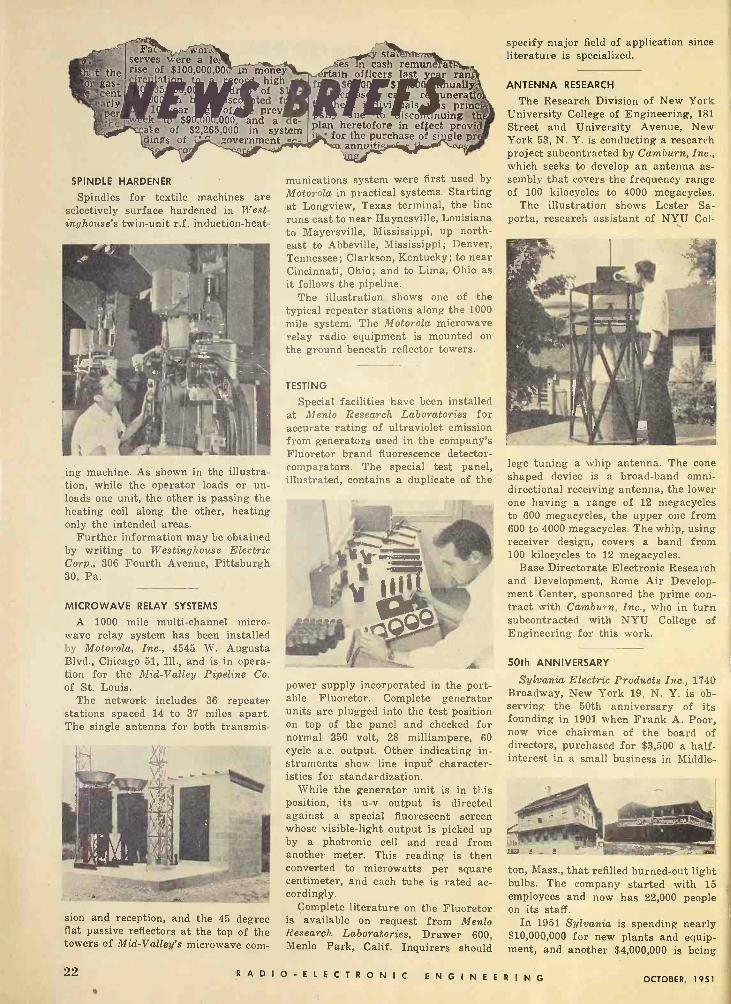
FaZZ wog... serves were a le; rise of $100,000,00 circlllat
nn money - co high
35 0i of $l 0 . sc ted f
1 r of prey k $91,101,000, and a e
abe of $2,265,000 in system dings of ' zovernment
o
SPINDLE HARDENER
Spindles for textile machines are selectively surface hardened in West- inghouse's twin -unit r.f. induction -heat-
ing machine. As shown in the illustra- tion, while the operator loads or un- loads one unit, the other is passing the heating coil along the other, heating only the intended areas.
Further information may be obtained by writing to Westinghouse Electric Corp., 306 Fourth Avenue, Pittsburgh 30, Pa.
MICROWAVE RELAY SYSTEMS
A 1000 mile multi -channel micro- wave relay system has been installed by Motorola, Inc., 4545 W. Augusta Blvd., Chicago 51, Ill., and is in opera- tion for the Mid -Valley Pipeline Co. of St. Louis.
The network includes 36 repeater stations spaced 14 to 37 miles apart. The single antenna for both transmis-
sion and reception, and the 45 degree flat passive reflectors at the top of the towers of Mid -Valley's microwave corn -
star es to cash remun
rtaìh officers last y r ran ually.
r uneratio aIs s princ
u isco nuing th plan heretofore in effect provid
- for the purchase of single pr annuiti
munications system were first used by Motorola in practical systems. Starting at Longview, Texas terminal, the line runs east to near Haynesville, Louisiana to Mayersville, Mississippi, up north- east to Abbeville, Mississippi ; Denver, Tennessee; Clarkson, Kentucky; to near Cincinnati, Ohio; and to Lima, Ohio as it follows the pipeline.
The illustration shows one of the typical repeater stations along the 1000 mile system. The Motorola microwave relay radio equipment is mounted on the ground beneath reflector towers.
TESTING
Special facilities have been installed at Menlo Research Laboratories for accurate rating of ultraviolet emission from generators used in the company's Fluoretor brand fluorescence detector - comparators. The special test panel, illustrated, contains a duplicate of the
power supply incorporated in the port- able Fluoretor. Complete generator units are plugged into the test position on top of the panel and checked for normal 350 volt, 28 milliampere, 60 cycle a.c. output. Other indicating in- struments show line input character- istics for standardization.
While the generator unit is in this position, its u -v output is directed against a special fluorescent screen whose visible -light output is picked up by a photronic cell and read from another meter. This reading is then converted to microwatts per square centimeter, and each tube is rated ac- cordingly.
Complete literature on the Fluoretor is available on request from Menlo Research Laboratories, Drawer 600, Menlo Park, Calif. Inquirers should
specify major field of application since literature is specialized.
ANTENNA RESEARCH
The Research Division of New York University College of Engineering, 181 Street and University Avenue, New York 53, N. Y. is conducting a research project subcontracted by Cam burn, Inc., which seeks to develop an antenna as- sembly that covers the frequency range of 100 kilocycles to 4000 megacycles.
The illustration shows Lester Sa- porta, research assistant of NYU Col-
lege tuning a whip antenna. The cone shaped device is a broad -band omni- directional receiving antenna, the lower one having a range of 12 megacycles to 600 megacycles, the upper one from 600 to 4000 megacycles. The whip, using receiver design, covers a band from 100 kilocycles to 12 megacycles.
Base Directorate Electronic Research and Development, Rome Air Develop- ment Center, sponsored the prime con- tract with Camburn, Inc., who in turn subcontracted with NYU College of Engineering for this work.
50th ANNIVERSARY
Sylvania Electric Products Inc., 1740 Broadway, New York 19, N. Y. is ob- serving the 50th anniversary of its founding in 1901 when Frank A. Poor, now vice chairman of the board of directors, purchased for $3,500 a half - interest in a small business in Middle-
V-
-etiereleseedgeID ton, Mass., that refilled burned -out light bulbs. The company started with 15 employees and now has 22,000 people on its staff.
In 1951 Sylvania is spending nearly $10,000,000 for new plants and equip- ment, and another $4,000,000 is being
22 RADIO -ELECTRONIC ENGINEERING OCTOBER, 1951

spent on replacement of existing ma- chinery and equipment, which repre- sents an all-time high for the company's investment in plant and machinery in any one year.
The mother plants of Sylvania are shown in the illustration. The frame structure (left) is the birthplace of the company at Middleton, Mass. The brick building (right) was occupied by the Pennsylvania branch soon after its founding.
NEW PERSONNEL
Dr. Richard M. Goldrick became re- search manager of the Fibron Plastics Department of the Irvington Varnish and Insulator Company. He was for- merly a research chemist with the Du Pont Polychemicals Department in Wil- mington, Delaware.
W. Moody Wilson joined the depart- ment as a research chemist. He had been previously engaged in the develop- ment of plastics in conjunction with medical applications for the past four years.
HARBOR RADAR
A successful test of harbor radar was announced by the Raytheon Manu- facturing Company, Waltham 54, Mas-
sachusetts. Unlike other harbor radar installations which merely use land based ship radar equipment, the Ray- theon Harbor Radar System is a com- pletely new approach to the problem, using equipment designed specifically for the purpose. Tests conducted in Boston Harbor on Deer Island were made under actual conditions en- countered in a busy harbor. Vessels were moved in and out of the harbor under conditions simulating zero -zero visibility. Orders were given to the ves- sel's pilot by means of two-way radio telephone equipment.
The antenna, the world's largest, is 41 feet wide and weighs approximately 10,000 pounds, which is more than three times larger than any shipboard type radar antenna and produces a beam
ANY SIZE
Spiral Wound
It pays to check your requirements with PARAMOUNT ... because you benefit from PARAMOUNT'S coil -proved design and construction-vast range of stock arbors-wide experience in engineering special tubes! Hi -Dielectric. Hi -Strength. Kraft, Fish Paper, Red Rope, or any com- bination wound on automatic machines. Tolerances ± .002'. ALSO: Shellac -Bound Kraft paper tubing. Heated shellac forms an adhesive bond between the laminations. Absolutely mois- ture resistant.
Paramount PAPER TUBE CORP.
613 Lafayette St., Fort Wayne, Ind. Mirs. of Paper TubingJor the Electrical Industry
7OPHAR WAXES
Colt.
Nos
Anti -Corona high heat -resistant
compounds for Fly Back Trans-
formers.
Waxes and compounds from
100° F to 285° F Melting Points
for electrical, radio, television,
and electronic components of
all types.
Pioneers in fungus -resistant waxes.
Our efficient and experienced laboratory staff is at your serv- ice.
uri e1
ZOPHAR MILLS, INC. 105r: 112-130 26th Street,
Brooklyn 32, N. Y.
PAPER TUBES
SQUARE RECTANGULAR TRIANGULAR HALF -ROUND
ROUND
Measurements Corporation e MOSEL 59
MEGACYCLE METER
The only
grid -dip
meter
covering the
wide ronge
of
2.2 Mc. to
400 Mc.
FREQUENCY CALIBRATION: ±2 For determining the resonant frequency of tuned circuits, an- tennas, transmission lines, by- pass condensers, chokes, etc. For measuring inductance and capacitance. May also be used as an auxiliary signal genera- tor; for signal tracing and many other applications.
Complete data on request.
MEASUREMENTS CORPORATION
BOONTON o NEW JERSEY
OCTOBER, 1951 R ADIO -ELECTRONIC ENGINEERING 23

width of only 42 minutes with a power gain of approximately 10,000. The in- dicator used on this system employs 16 inch tubes, thus by offsetting and eliminating unwanted objects the pres- entation is the same as would be seen on a 32 inch tube.
The Harbor Radar System also em- ploys the Raymark Beacon System for identification of specified vessels and also employs specially designed lubber - lines for obtaining bearings between two vessels and for obtaining fixes when using the special offset indicators.
NEW PUBLISHERS ASSOCIATION
A new national industry organiza- tion, the Technical Publishers Associa- tion, 30 Vesey Street, New York 7, N. Y., recently came into being when some 28 owners and operators of tech- nical publishing concerns adopted a constitution and elected a board of directors and officers at a meeting held in New York City.
Among the objectives of the new asso- ciation are: (a) to engage in research and to analyze the practice of technical publishing to improve its standards and techniques; (b) to foster training and education of persons preparing to enter the technical publishing profession and to cooperate with educational institu- tions; (c) to promote recognition of the profession as an essential service to industry and government; (d) to conduct research and consider "intra - professional problems"; (e) to cooper- ate with industry and government in de- veloping standardization and simplifica- tions to enable members to offer more economical, expeditious and intelligent services; and (f) to assist in develop- ing fair bidding and purchasing prac- tices and sound employment policies.
FALL MEETING
The 1951 Radio Fall Meeting will be held in the King Edward Hotel, To- ronto, Ontario, Canada from October 29th through 31st, according to an an- nouncement by Virgil M. Graham, chairman of the meeting and director of technical relations for Sylvania Elec- tric Products, Inc. Graham said that there would be no advance registration for the meeting but that those who attend should make hotel reservations early.
Tentative program for the three day sessions will include general sessions Monday morning, October 29 including an address by Ivan S. Coggeshall, presi- dent of the Institute of Radio Engi- neers; Monday afternoon sessions will be devoted to the reliability of tubes and circuits, sponsored by the IRE Professional Group on Quality Control.
(Continued on page 30)
Gate and Delay (Continued from page 11)
rings positive, but is damped out when it tries to ring negative. Thus the diode CR, insures only one positive pulse, and that at the end of the delay inter- val. This pulse is also shown in Fig. 4c, on a faster sweep.
Because the gate is a.c. coupled to the cathode follower, the amount of current flowing through the peaker dur- ing the delay interval varies with the duty factor. The pulse therefore also varies with the duty factor, but is al- ways large enough to trigger the pulse generator in the following stage.
The pulse generator, V4, is a single - shot multivibrator that is triggered by the pulse generated in the plate circuit of the cathode follower at the end of the delay interval. The right-hand half of this tube is normally on, and it holds the left-hand half off by means of the common cathode coupling. The pulse from the plate of the cathode follower triggers this circuit, causing the left- hand half to conduct and a negative - voltage pulse to appear at the left-hand plate. This waveform, seen in Fig. 4d, is capacitor -coupled to the right-hand grid of V,. The grid -circuit time con- stant is quite short, so that the circuit recovers very quickly. When the right- hand half of V, is cut off, the peaker in its plate rings positive, the negative overshoots being damped out by con- duction of CR,. When the circuit re- turns to its normal state, a second negative pulse appears as current is again built up in the inductance.
The waveform shown in Fig. 4e is capacitor -coupled to the grid of the output buffer, V,. This buffer is nor- mally biased off, and it therefore am- plifies only the positive portion of the pulse. The resulting output pulse at V. is at a 93 ohm impedance level, and may be seen in Fig. 4f, driving 93 ohms. Its length is approximately 0.1 micro- second, and its amplitude may be varied from 0 to 40 volts. Polarity is reversible by use of switch S,.
Suggested Improvements in the Circuit
Several improvements are suggested by the authors as possible changes in circuit design if many of the present uses for the unit continue. For example, thè gate output is generally fed to one of the control grids of a gate tube, whose cathode is usually grounded. It would therefore be very convenient to have the gate d.c. coupled to the output jacks, and to have the two d.c. levels involved, in the order of -20 and +5 volts. This feature could be accom- plished by driving the grid of the cath- ode follower by the divider that already
drives the grid of V.A. Grid -to -cathode conduction of V,4 limits the positive swing of this point during the delay interval, and would nicely establish the level of the top of the gate. The level of the base line could be controlled by choosing the proper negative voltage to which to return the cathode resistor of the cathode follower. If this voltage is chosen so that the tube is cut off between delays, no overshoot would be observed at the output.
The pulse generator could be simpli- fied if the above modifications were used, since the shape of the pulse fed to it from the plate of the cathode follower would be independent of duty factor, but the need for a generator would not be eliminated. The reason is that the current through the cath- ode follower does not collapse rapidly enough at the end of the delay interval to generate a satisfactory pulse in a peaker designed for 0.1 µsec.
In general, the unit has performed very satisfactorily. The major difficulty in previous models, which was caused by variations in the power source, has been taken care of by the inclusion of voltage -regulator tubes. The changes suggested above are minor, but come from long and varied use of equipment in the laboratory.
RC Filters -
(Continued from page 6) Each of these filters consists of two
sets of two high-pass and two low-pass constant -k sections, as shown in Fig. 12. These filter circuits are quite conven- tional in design, and are designed to match terminal impedances of the order of 10,000 ohms. In the interests of uni- formity, these LC filters are used with the same amplifiers and are mounted in the same plug-in cans as are used in the RC sections. Since the insertion loss of the LC sections is different from that of the RC units, the LC plug-in units contain appropriate loss networks and certain sections of the T circuits are bridged out inside the cans. By the use of this arrangement, identical ampli- fiers are used at all frequencies, and the filter units from any one amplifier can be plugged into any other without adjustment or change.
The frequency response curves at -
Fig. 12. LC filter used to give band- pass frequency characteristic for highest frequency range. Two such filters are used for each channel.
24 RADIO -ELECTRONIC ENGINEERING OCTOBER, 1951

i
Fig. 13. The wiring and internal construction of a com- plete band-pass unit whose schematic is shown in Fig. 11.
tained by the use of the filter circuits which have been described are shown in Fig. 14. A set of sample response curves is shown, to illustrate the band- pass characteristics at the extremes and at the center of the frequency range covered by the equipment. These curves show the response of the RC networks for the 15-30 cycle, the 400-800 cycle, and the 8000-15,000 cycle bands, and the LC network for the 80-160 kilocycle band. They show that the band-pass response curves are approximately the same at all frequencies within the range of the instrument, and that the same type of frequency response is obtained from the RC filter circuits as from the LC filters.
The actual construction and physical layout of the filters can be seen from the photograph in Fig. 13, by compar- ing it with the block diagram of Fig. 10 and the circuit schematic of Fig. 11. The basic amplifier chassis contains all
o
-10
20
tn Z 30 á
40
50
-60 10
the feedback -pair gain stages, and is so arranged that all the frequency -re- sponse components are mounted in the four plug-in cans. Thus, the same basic amplifier unit is used for all of the band-pass filters, with the frequency response determined by the particular set of filter cans which is plugged into the amplifier.
The method of obtaining the filter responses from RC circuits described in this article is not essentially new in principle, but it is believed that the cir- cuits which are used in this system rep- resent a distinct advance in the utiliza- tion of such networks. By extending the principles of conventional filter theory to the design of RC filters, they make it possible to obtain sharp -cutoff filter characteristics at very low fre- quencies at which it has prebiously been impractical to obtain the maximum benefits of such networks.
Fig. 14. Typical band-pass frequency response curves to illustrate the band-pass characteristics at extremes and at center for frequency range.
r
9
I I
I00 IK
FREQUENCY IN cp IOK IOOK
"USE THE BEST FOR TEST
The AUDIO OSCILLATOR that stresses quality in design,
construction and performance.
Laboratory
Type TE200K
COMPARE THESE FEATURES:
1. All capacitors are hermetically sealed in oil or m;ca-no electro- lytic capacitors are used.
2. Stable operation assured under varying line voltage conditions through use of electronically regu- lated power supply.
3. Thermal drift minimized through use of "temperature design" and low temperature coefficient resis- tors, thereby eliminating constant zero setting.
4. Mounts in standard relay rack or table cabinet.
SPECIFICATIONS:
Frequency Coverage: 20 cycles to 200,000. cycles in four ranges. Frequency Dial: 6" diameter, direct reading, with planetary drive. Output Voltage: 0 to 10 volts con- tinuously variable. Calibration Accuracy: ±2% of dial setting indication. Average Distortion: 1% Hum Level: Minus 50 DB or better. Standard Load: 1000 ohms resistive. Frequency Response: ±-1 DB from 20 to 200,000 cycles. Drift: ±20/, or better. Power Supply: 115 volts 50/60 cycles, 60 watts.
For further details write to:
EL-TRONICS INCORPORATED
2647 N. Howard St. PHILADELPHIA 33, PENNA.
OCTOBER, 1951 R ADIO -ELECTRONIC ENGINEERING 25

rsona1 WILLIAM AVILA has been elected vice-president and plant manager of Bardwell & McAlister, Incorporated. Mr. Avila has engineering degrees from Princeton University, Southern California, the Massachusetts Institute of Tech- nology, and California University at Berkeley. He served as a radar officer during the last war, and upon release from service, became production engineer for the Atomic Energy Commission.
OTTO C. BILLER has been appointed director of engineer- ing of Magnecord, Inc. Mr. Bixler was formerly associated with Airesearch Manufacturing Co. as electrical develop- ment engineer on aircraft and guided missile applications of special electronic equipment. He received his electrical engineering degree from the University of Southern Cali- fornia, and is a member of Eta Kappa Nu, Tau Beta Pi, AIEE, and SMPTE.
DR. IVAN A. GETTING has been elected vice-president of Engineering & Research at Raytheon Mf g. Co. An out- standing authority on radar, Dr. Getting held the post of chief scientist of the U. S. Air Force, and in recognition of his work during the war received the President's Medal of Merit. He is a Fellow of the American Physical Society, senior member of the IRE, and a Fellow of the American Academy of Arts & Science.
LEON HILLMAN has recently been appointed head of the engineering department of Production Research Corporation, located at Thornwood, New York, where his duties will be to officiate as director of engineering. Mr. Hillman had formerly been affiliated with the research division of the New York University. Production Research Corporation specializes in the research, development, and production of electronic equipment for the Armed Forces.
DR. RICHARD F. HUMPHREYS has been named chair- man of the physics department at Armour Research Found- ation of Illinois Institute of Technology. In his new position, Dr. Humphreys will head research activities in acoustics and vibrations, high pressure, nucleonics, light and optics, physics of solids, etc. He is a member of Sigma Xi, Ameri- can Physical Society, and the American Association for the Advancement of Science.
RALPH B. LADD has been named chief of the electronics division of the Office of Aviation Defense Requirements of Civil Aeronautics Administration. Mr. Ladd joined CAA in 1933, and had been chief of the Chicago Electronic Section until transferred to Washington last year. His prime duties now will be responsibility for all Federal Airways require- ments programs and Airborne Electronics & Electrical re- quirements for Civil Aviation.
New Products (Continued from page 21)
effective for devices requiring adjust- ment in a vacuum, enabling the opera- tor to "reach into the vacuum" to make adjustments without affecting the vac- uum seal in any way. As a hermetic seal, the bellows permits 360 degree rotation while maintaining 100% me- tallic seal.
A few of the numerous applications for these bellows are for magnetron tubes, in order to insure the vacuum tight chambers even after high temper- ature bakeout at 900° F for several hours under condition of practically zero air pressure internally and atmos- pheric pressure externally, and for ex- pansion chambers in mercury filled waveguides, as well as for switch mech- anisms and other electronic applica- tions.
SWITCH
General Control Company, Boston 34, Massachusetts, announces a small, standard, telephone -type switch, type
MCT. Maximum depth of this unit in back of panel is 21/2 inches; width is % inch, thus providing compactness for multiple mounting on crowded con- trol panels, and is available in two mounting styles: single 1/2 inch thread- ed bushing, or 3-48 tapped holes to fit all universal mounting requirements.
A feature of MCT switch is the shielding between pairs of contact as- semblies, for contact isolation where necessary. Contacts are either fine sil- ver or silver palladium alloy, and carry ratings of 1 ampere, 115 volts a.c., non - inductive load.
RESISTORS
Miniature hermetically sealed resis- tors with solder lug terminals and de- signed to meet the requirements of JAN - R -93, characteristic A, style RB11, have been announced by the Shallcross Manufacturing Co., Collingdale, Penn- sylvania.
Known as Shallcross Akra-ohm type 1180, the resistors are 19/32 inch long
26 RADIO -ELECTRONIC ENGINEERING OCTOBER, 1951

by 1 inch diameter and are rated 0.25 watt at 250 volts. Resistance values up to 0.1, 0.3 or 0.4 megohms may be ob-
tained depending on the alloy wire used for the non -inductive winding. The units are hermetically sealed in Stea- tite by a process which provides posi- tive immunity against the effects of humidity, fungus and salt water immer- -ion.
ATTENUATOR
Polarad Electronics Corporation, 100 Metropolitan Avenue, Brooklyn 11, N. Y., announces a new external broad-
band microwave attenuator, Model SIJ. This unit operates on the principle of a waveguide beyond cut-off and pro- \ ides a range of attenuation in excess of 140 db. The attenuator is designed to cover the frequency range from 4 to 12 kmc., and has a 50 ohm impedance.
BALL BEARING
The New Hampshire Ball Bearings, lac., Peterborough, N. H., announces
a new spring -retainer Micro ball bear- ing. Formerly obtainable in larger sizes only, this new bearing measures
ßßa" bore x g" OD x IA" wide, in toler- ances ABEC 5 and higher. Character- istics include low and uniform values of starting or breakaway torque, a high percentage falling in the range .0006 inch -ounce under a standardized 75 gram thrust load. Individual stainless steel coil springs serve as separators. Rings and balls are standard in high - carbon chrome steel.
SOUND LEVEL METER
Type 410-B sound level meter is used for accurately measuring noise, sound, and vibration, which often have harm- ful effects on human nerves, efficiency, and hearing. This very rugged, corn -
pact, and accurate instrument is made possible by use of subminiature tubes and components, together with patents - pending miniaturization techniques, and
meets all specifications of the Ameri- can Standards Association.
This unit features greater low -fre- quency range, from 34 to 140 db above the standard ASA reference level of 0.0002 dynes per square centimeter. Hearing -aid batteries are used, having an operating life of about 50 hours. The unit is available with carrying case, extension cables and vibration measuring equipment. For a bulletin and further information write Hermon Hosmer Scott, Inc., 385 Putnam Ave- nue, Cambridge 39, Mass.
WELDING ROD
Chemalloy Asoociates at Gillespie Airport, Santee, California announces a new type of welding and soldering material which particularly simplifies the art of aluminum welding and weld- ing of pewter or potmetals. The Chem - alloy welding rod is d rived by mixing together molten metal' from less criti- cal scrap or virgin zinc, copper, alumi- num, lead, tin and slag plus an admix- ture of wet chemical masses.
To use as welding rod or solder, the. aluminum is heated to its softening point, and the chemalloy metal is rubbed on, no flux being necessary.
PRECISION COIL BOBBINS
With Better Insulation, Moisture -Resistance and Heat -Dissipation
Strict Laboratory Control of materials en- ables Precision to offer you bobbins that are 15 to 20% stronger, yet light in weight - that have greater insulation, moisture -re- sistance and heat -dissipation, too. Increased coil winding space is another vital feature of Precision Coil Bobbins.
Flanges furnished with leads, slots, holes or plain-all types supplied flat, recessed or embossed to fit any mounting. Tube ends swaged to lock flanges. Any size, any shape available - round, square, rectangular - in dielectric Kraft, Fish Paper, Cellulose Ace- tate or combinations. Send Specifications for Sample and Ask for New Mandrel List of 1000 Sizes.
PRECISION PAPER TUBE CO. 2063 W. Charleston St.
Chicago 47, Ili. Plant No. Two, 79 Chapel St., Hartford, Conn.
Also Mfrs. of PRECISION PAPER TUBES
OCTOBER, 1951 RADIO -ELECTRONIC ENGINEERING 27

l'il'I' E N'I' REVIEW
Printed copies of these or any other pat- ents may be obtained from the U. S. Patent Office for 25e each. Address the Commis- sioner of Patents. Washington 25, D. C.
ELECTRIC PICKUP FOR VIBRATIONS
This invention describes a system for converting mechanical vibrations into electrical impulses by the aid of a
capacitance which varies in accordance with the vibrations. It is particularly useful in picking up vibrations from a vibrant bar or chime.
The device consists essentially of a semicircular metal strip placed on the bar or chime, and insulated from it by means of a suitable dielectric material. It is held in place by clamps. The bar or chime then forms one plate of the condenser and the metal strip of other plate. Vibrations in the bar are con- verted to variations in capacity, which in turn may be converted into electrical variations by suitable circuitry.
Patent No. 2,553,927 was issued May 22, 1951 in the name of L. A. Maas.
HIGH -FREQUENCY GENERATOR
The object of this invention is to provide an improved device for generat- ing high frequency oscillations by veloc- ity modulating a beam of electrons by means of a relatively low frequéncy.
A conventional cathode-ray tube gun
and electrostatic deflection system is used. Following the deflection system is a group of grid segments placed in a circle, each successive segment being
charged with a potential of opposite polarity. The electron beam is caused to rotate so that it passes through the various grids in succession; thus the beam is alternately accelerated and re- tarded. This will result in bunching. Energy extracting grids intercept these bunches, and a resonant circuit is pro- vided which will oscillate when the bunching frequency is correct.
Patent No. 2,554,117 was issued May 22, 1951 in the name of Angelo Montani.
SECONDARY EMISSION AMPLIFIER
Many proposals have been made for constructing an amplifying vacuum tube utilizing secondary emission. The present invention is a development along these lines and certain advan- tages over previous designs are claimed.
Electrons emitted from a cathode are formed into a beam by suitable elec-
trodes, and pass through a control grid, accelerating grid and suppressor. The beam then passes through a special collector grid and strikes a surface capable of emitting more secondary electrons than there are electrons in the primary beam. These secondary electrons are collected by the collector grid, on which now appears an am- plified signal.
An improved method for activating the secondary electron emitting sur- faces is provided for, which eliminates
contamination sometimes acquired dur- ing the activation process.
Patent No. 2,553,997 was issued May 22, 1951 in the name of Albert Atherton.
DYNAMIC COMPRESSOR AMPLIFIER
_The compressor described in this in- vention consists of an L pad attenuator made up of the two sections of a dual triode. During compression, the series tube gain increases, and the impedance
of the shunt tube decreases, thus reduc- ing the amplitude of the signal. At very low signal levels, the series tube ampli- fies normally.
Two separate rectifier systems are connected in the output of a control amplifier stage. The output control volt- age of one system increases and the other decreases when the input signal increases. These control voltages are connected to the grids of a dual triode.
Patent No. 2,553,673 was issued May 22, 1951 in the name of E. S. Purington.
PROTECTIVE SYSTEM
This is a protective system for cut- ting off the spot on a cathode-ray TV tube in case of failure of the horizontal or vertical sweep. It is desirable where the high voltage is obtained from some source other than the horizontal sweep, such as projection tubes where voltages as high as 80 kv. may be used.
In the present invention, a portion of the voltage driving the horizontal sweep is rectified and filtered. This d.c. voltage biases a thyratron so that it will not conduct. If the horizontal oscil- lator should fail, no bias will appear on the thyratron, and it will conduct, developing a voltage across its load re- sistor. This voltage is impressed on
the control grid of the cathode-ray tube cutting off the electron beam and pre- venting damage to the screen.
Patent No. 2,536,712 was issued Jan- uary 2, 1951 in the name of William A. Behtley.
28 SDIOELECTRONIC ENGINEE RING OCTOBER, 1951

i
T V3181(914 t"FUNDAMENTALS OF ATOMIC
PHYSICS" by Saul Dushman. Pub- lished by McGraw-Hill Book Company, Inc., 330 West 42nd St., New York 18, N. Y. 294 pages. $5.50.
Designed to be as simple as possible in treatment, this book gives engineers and other technical men a practical knowledge of the atomic and nuclear fundamentals they will be encountering more and more in their work. The vol- ume includes a thorough treatment of the Kinetic theory of gases, the charge and mass of the electron, electronics, photoelectric effects, x-rays, the Bohr theory of the origin of spectral lines, electron configurations in atoms-with a coverage of matter waves, isotypes, and other important factors.
Only elementary calculus is used, and as much emphasis as possible is placed on experimentally observed phenomena. A brief chapter deals with the history of physics, and another summarizes elementary mathematical techniques necessary in order to present this theory in a logical manner, without bringing in more complicated and ab- struse considerations. Special features include the most recent advances in the investigation of nuclear phenomena, the development of atomic energy and the production of high -voltage particle accelerators.
t'ELEMENTS OF TELEVISION SYSTEMS" by George H. Anner. Pub- lished by Prentice -Hall, Inc., 70 Fifth Avenue, New York, N. Y. 804 pages. $10.35.
This book is divided into three parts; the first dealing with a study of closed systems, those that rely upon cable con- nections between sending and receiving apparatus, thus the basic problems of any TV system can be studied independ- ently of the problems associated with broadcasting the signal by radio.
In the second part of the book the point of view is expanded to include the complications introduced by using a radio link in place of inter -connecting cables. And the last part is concerned with methods of super -imposing color - perception on a system which is inher- ently color blind.
Since details of a new art change rapidly, an attempt is made to concen- trate on the basic principles involved. The new technique of dot interlace, which promises to become very impor- tant in the future, is covered in the appendix.
Magnetic Attenuator (Continued front page 18) enough to reduce the attenuation 60 per -cent, change the power by a ratio greater than 60:1, with a voltage stand- ing wave ratio always less than 1.5.
More recently, a study was made at NBS of an attenuator that employs a slug of Ferramic B 1/a inch long and % inch in diameter as the dissipative me- dium. The dependence of the losses in the material on frequency was remark- ably demonstrated by this experiment. At 2200 mc. the attenuation was re- duced from 17 db to less than 3 db, and less than 45 milliamperes of current was required to maintain the magnetic field. At a frequency of 2600 mc., changes in attenuation greater than 20 db were obtained with the same electro- magnet currents. To avoid saturation in the iron core of the small, low cur- rent electromagnet, a larger unit was used to obtain greater changes in at- tenuation. At several frequencies, at- tenuation changes in excess of 95 per- cent have been obtained without diffi- culty.
While operating at a frequency of 3200 mc., a striking example of ferro- magnetic resonance was exhibited. As the electromagnet current was in- creased, the attenuation decreased from its initial value of 24 db to about 18 db, then peaked to about 25 db, and finally decreased to approximately 1 db. The peak occurred at a current of approximately 0.6 amperes. When operating at 3700 mc., a similar phe- nomenon occurred. The initial attenua- tion of 26 db was reduced to about 16 db before peaking to 37 db; finally it dropped to about 1 db as the cur- rent continued to increase.
Many applications of this magnetic phenomenon are immediately evident. An audio source can be used to vary the electromagnet current which produces a. changing field in the attenuator and consequently amplitude modulates the r.f. signal. The resultant modulation envelope includes the predominant sec- ond and higher harmonic frequencies of the audio frequency field. However, these harmonics can be readily elimi- nated by employing a d.c. bias about which the a.c. field oscillates. The use of the NBS Magnetic Attenuator in this fashion permits amplitude modu- lation of uhf and microwave oscilla- tor outputs without the frequency mod- ulation effects which occur when the oscillator is modulated directly.
The NBS Magnetic Attenuator is equally adaptable as an output stabi- lizer for microwave oscillators. The unit can be part of a degenerative feed- back circuit in which the magnitude of the field produced by the electromagnet
It's
TYPE BH6A RANGE: 1.4 - 75.0 me Supplied per Mil type CR -18; CR -19; CR -£3; CR -27; CR - 28; 3R-32; CR -33; CR -:,5; CR -36 when spec: fied.
.Dependability is a composite virtue that Bliley builds into all crystals. From raw quartz to finished crystal, exacting inspection assures dependable per- formance. That's why Bliley methods and techniques are a "natural" for military as well as civilian applications.
iC TYPE MC9 RANGE:
1.0 - 10.0 mc Supplied per Mil type CR -5; CR -6; CR -8; CR -10 when specified.
IC TYPE SR5A RANGE:
2.0 - 15.0 mc Supplied per Mil type CR -1A when specified.
IC TYPE AR23W RANGE: 0.080 -
0.19999 mc Supplied per Mil type CR -15; CR -I6; CR -29; CR -30 when specified.
*TYPE BH7A RANGE:
15.0 - 50.0 mc Supplied per Mil type CR -24 when specified.
liteq CRYSTALS
BLILEY ELECTRIC COMPANY UNION STATION BUILDING
ERIE, PA.
OCTOBER, 1951 R ADIO -ELECTRONIC ENGINEERING 29
f
The magnetic attenuator (top) separated Into its essential components (bottom).
is controlled by a small amout.t of r.f. power taken from the coaxial transmis- sion line. Another magnetic unit may also be utilized in such a feedback net- work. The rectified control voltage cou- pled from the transmission line may be applied to a magnetic amplifier which controls the electromagnet field directly
Current NHS investigations are be-
ing directed toward finding better and more efficient dissipative materials. Among the latest group of materials under study are magnetic ferrites, which yield greater attenuation changes for a given electromagnet current than does polyiron. These ferrites should thus make possible the use of smaller currents to produce the same changes of attenuation. +®+
©AgrAD2/1 ei ea/we EueKtQ
OCT. 8-10 - Fall Meeting of U.S.A National Committee of URSI and IRE Professional Group on Antennas and Propagation, Ithaca, N.Y. OCT. 22-24 --7th Annual National Elec- tronics rderence, Edgewater Beach Hotel, Chi ,ago. OCT. 22.2$ - Fall General Meeting. ALEE, Cleveland, Ohio. OCT. 23-25--Fcrty-seccnd mr .
e Arc usttcii clety cf A'.. rman Hole! C.1-agc ill.
OCT. 2S ---Twentieth anniversary ct it.. Ac. m Institute of Physics. Sher min ilotel, Chicago. LI
OCT. 21-31-Radio Fall Meeting. Cron Edward Hotel, Toronto, Ont., Canada. NOV. 1.3 - Audio Fair, Hotel New Yorker. New York City. DEC. 1012 -- joint IRE-AIFE Compute! Conference. Benjamin Franklin Hotel Ph!Iaddr'L., T]
The Series amplifier it. baked front page 13)
bandwidth and, at the same time, in-
crease the gain. One trick which has been used with
great success in making compact ampli- fiers is to calculate the value of load
resistor required, convert it to the equivalent series resistance needed, and then wind the coil with insulated resist- ance wire of the proper gauge to give
the right number of "turns" and "ohms" simultaneously. The relation between equivalent parallel and series resist- ance for loading i.f. coils is: R,...,. = R,.,,.,/ (1 + Q)'.
Another trick which may be used, pro- vided the stage bandwidth required is 5
megacycles or more, and the signals to be handled are small (1 volt or less) , is to operate the tubes at zero bias. This is an excellent way to save space, since it eliminates a resistor and capacitor in each stage, but remember the band- width and signal requirements, and be sure to measure the series plate cur- rent and keep it within the rated limit. The use of zero bias will require B+ voltage of only about 50 volts per stage. A schematic of the zero bias circuit is shown in Fig. 5.
It is, of course, possible to operate the series amplifier string on an in- verted power supply. In this circuit, B+ is grounded, as is the last stage plate return; and the first cathode is bypassed to ground and fed with high B-. This is a convenient way to have the detector operate at d.c. ground potential.
The above remarks apply, in general, to front ends of tuners. It might be well to point out that the Wellman or cascode low noise circuit is especially suited to the series amplifier circuit. Several adaptations of the series -type Wellman circuit have been built and perform satisfactorily. Their simplicity is unexcelled.
Low frequency amplifiers are another classification in which the series ampli- fier can be applied. Very high -gain, compact, audio voltage amplifiers can be built with this technique. The cou- pling impedance is an audio choke. It should have the same characteristics as the audio choke in conventional ampli- fiers, namely, maximum inductance at rated d.c. current for good low -fre- quency response, and minimum self -ca- pacitance for a high resonant frequency and good high frequency response.
When using the series amplifier method for a Class C frequency multi- plier string, high bias voltage must be obtained either by using a large cath- ode bias resistor or by using RC cou- pling in the grid circuit. The latter method does away with one of the chief
advantages of the series amplifier, sim- plicity; but the convenience of a low -
current, high -voltage B}- requirement remains.
Narrow -band i.f. amplifiers, suitable for communications receivers, can also be connected as series amplifiers. Nar- row bandwidth tuned circuits are of prime importance in this application. It must be admitted that transformer coupling is superior in this respect, and if need be, transformers can be used. In any case, shunt capacitance tuning with no resistive loading, and high coil Q should be used. If the shunt capacity is relatively large, the bypass on the cathode resistor can be omitted without any undesirable increase of bandwidth, although degeneration will produce somewhat smaller gain. To avoid de- generation, the bias resistor may be placed in series with the tank circuit. This circuit is shown in Fig. 4.
Many more adaptations of the series amplifier will suggest themselves to the reader. Actually a number of interest- ing applications have been omitted be- cause of limited space. It is hoped, how- ever, that the information presented here will furnish material for experi- mentation and study by interested engi- neers and technicians. Here then, is the series amplifier. What will it do for you? .
NI'WS Briefs (Continued front page 24)
Tuesday will include a symposium on color television moderated by D. B. Smith, vice chairman of the National Television Systems Committee. Wed- nesday morning sessions will be spon- sored by the IRE Professional Group on Audio and Wednesday afternoon will be devoted to television.
MEN AND MACHINES
An article entitled "Electronics and Human Beings," in the August issue of Harper's magazine, urges that ma- chines replace men wherever possible in order to eliminate waste of tech- nology. The authors, E. W. Leaver and J. J. Brown, point out that the tinte is at hand for the electronic manage- ment not only of industrial production but of business and governmental com- munication, of financial movement, and of commercial distribution. The article states, "Widespread use of automata (machines, not men) may bring an era of peace and creative human develop- ment, with the amelioration of national and individual neuroses. Men should not be used for routine operations and the automaticity of machines should be encouraged."
30 s A D I O- E L E C T R O N I C ENGINEERING OCTOBER, 1951
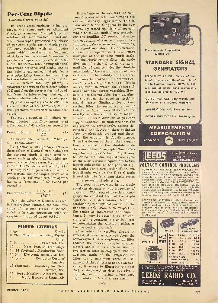
i
Per -Cent Ripple (Continued from page 32)
In recent years engineering has em- ployed the nomograph, or alignment chart, as a means of simplifying the solution of mathematical equations. The nomographs presented are charts of per -cent ripple for a single-phase, full -wave rectifier with an inductor input which operates at a frequency of sixty cycles per second. These nomo - graphs encompass a single -section filter and a two -section filter having identical component sections, and enable one to find quickly the per -cent ripple for a particular LC section without resorting to the solution of an algebraic equation. This is accomplished by placing a straightedge between the selected values of L and C on the outer scales and read- ing from the intersecting point on the center scale the value of per -cent ripple.
Typical examples given below illus- trate the use of the nomographs and the agreement of results with calculated values.
The ripple equation of a single -sec- tion, inductor -input filter operating at a frequency of 60 cycles per second is:
Per -cent Ripple = 83 X 100 LC
As an example, assume L = 2 henrys, C = 10 micaofarads.
By placing a straightedge between these values of L and C on the diagram the per -cent ripple is read from the center scale as about 4.2%, which ap- proximates within reasonable limits the value of 4.15% calculated from Eqt. (1) .
The equation of per -cent ripple for a two -section, inductor -input filter of a single-phase, full -wave rectifier operat- ing at a frequency of 60 cycles per second is:
146 X 10.12 Per -cent Ripple = (2)
Using the values of L and C as given in the previous example, the calculated value of per -cent ripple is 0.366%, which is in close agreement with the graphic solution of about 0.37%.
PHOTO CREDITS Page Credit 3, 25.. Fairchild Recording Equip.
Corp, 7, 9 Tracerlab, Inc. 10 Mass. Inst. of Technology 14, 16 (bottom) ..Remington Rand 15 (top) Electronic Associates, Inc. 15 (ctr.) Computer Corp. of
America 15 (bottom) .. Laboratory for Elec-
tronics, Inc. 16 (top) ..Northrop Aircraft, Inc. 18 ....Nat'l. Bureau of Standards
It is of interest to note that the com- ponent scales of both nomographs are characteristically logarithmic. This is true since L and C appear in the two previously stated equations of per -cent ripple as mutual multipliers, symboliz- ing the familiar LC product. Because the equations of per -cent ripple con- tain no algebraic sums or differences, the respective scales of the inductance, L and the capacitance C are exact multiples of the per -cent ripple scale. For the single -section filter, the scale divisions of either L or C are .exact multiples of exactly twice the absolute magnitude of the scale divisions of per- cent ripple. The validity of this state- ment may be proved in a mathematical sense by referring to Eqt. (1). This is an equation in which the factors L and C are first degree variables. How- ever, since the variables form an alge- braic product, the equation -itself is second degree. Similarly, for a two - section filter the respective scales of inductance L, and capacitance C, are exactly four times the absolute magni- tude of the scale divisions of per -cent ripple. Equation (2) indicates that the expression is, respectively, second de- gree in L and C. Again, these variables form an algebraic product and there- fore, the equation is fourth degree. Thus the degree of the algebraic equa- tion is related to the absolute scale divisions of the nomograph. Summariz- ing, for a single -section filter, it may be stated that one logarithmic cycle on the L or C scale is equivalent to two logarithmic cycles on the per -cent rip- ple scale; for a two -section filter, one logarithmic cycle on the L or C scale is equivalent to four logarithmic cycles on the per -cent ripple scale.
The constant appearing in the ripple equations depends on the frequency of operation. With regard to either nomo- graph the constant term of the ripple equation is a determining factor in establishing the physical position of the per -cent ripple scale with respect to the scales of inductance and capaci- tance. It may be stated that the con- stant of the equation is a shift factor in determining the relative position of the per -cent ripple scale.
Concerning the rectifier circuit in general, it may be observed from the nomographs that a single -section filter reduces the per -cent ripple approxi mately one -tenth as much as when a two -section filter is employed. The in- ductance scale of the single -section filter has a maximum value of 100 henrys. Although this is not a practical value, it serves to illustrate the fact that a single -section does not give a high degree of filtering unless very high values of L and C are used.
2;11111P
Measurements Corporation MODEL 78
STANDARD SIGNAL GENERATORS
FREQUENCY RANGE: Choice of two bands; frequency ratio of each band 1.8 to 1 within range of 10 Mc. to 250 Mc. Special single band instruments also available up to 420 Mc.
OUTPUT VOLTAGE: Continuously vari- able from 1 to 100,000 microvolts.
MODULATION: AM, fixed at 30%.
POWER SUPPLY: 1 17 v., 50/60 cycles.
ALS Our 29th Year QUALITY -PRICE DEPENDABILITY
VOLTAGE CONTROL PROBLEMS POWERSTAT VARIABLE TRANSFORMERS are autotransformers of toroidal core design with a movable brush tap which rotates to deliver a con. tinuously adjustable output voltage from a -c power lines. They are available as manually oper- ated or motor -driven models. POWERSTATS fea- ture- excellent regulation, conservative ratings, standard mounting, smooth control and high effi- ciency. They are offered in 115, 230 and 460 volts; single and three phase; 50/60 and 400/800 cycle types in capacities of 405 VA 60 100 KVA.
5 -WAY BINDING POSTS 5 methods of connection. Complete insulation, 30 amp, current capacity, 1000 v. working voltage. Captive head for con- venience. Red or black color. .5 connections: 1. Permanent clamping. 2. Spade Lug. 3. Plug-in for Banana Plug. 4. Looping and Clamping. 5. Clip -Lead.
TYPE 116
TYPE 20
00 FIXER
TYPE 1156
BINDING POST
Type amps. List Price 20 .... 3.0....5 12.50 116 .. 7.5,,,, 23.00 116U .. 7.5.... 18,00 1126 15.0,,,, 46.00 1156 . 45.0,,,, 118.00 1256 . 28.0.. . . 118.00 Binding Posts DF3OBC (Black). .40 DF3ORC (Red) .. .40
I. not rated 25% with order. balance C.O.D. All Prices F.O B. our.worehouse Ned Ynrk. No order under $2.00
We ship to ans Part of the rlóbe.
LEEDS RADIO CO. 75 Vesey Street Dept. Pry 9 COrtlandt 7-2612 New York City 7
OCTOBER, 1951 RADIO -ELECTRONIC ENGINEE RING 31
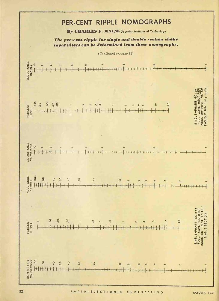
PER -CENT RIPPLE NOMOGRAPHS By CHARLES F. HALM, Fournier Institute of Technology
The per -cent ripple for single and double section choke input filters can be determined from these nomographs.
(Continued on page 31)
w ZN O 0) m n {0 1n Q M N
"= 1 1 1 1 1 1- F 1
1 IIIIII{11111I++I1111 I I I I I I I I 1 1
zW 0. Z
N M 7 o o 0.°.
I 1 111111111) I I I III11111I1 I I I IIII I1111 I I
r t r I I I I I
W N U 0 z.,0 p, coact
ó I l I I I {
N I 1.'". _ N M Q h Oo
a M N
I f1I11 I111I I 1 I I{ 1 1{ I f 1 1 { I I I I 1 1 1 1 I I I 1 } I I 1 I
(
w O U 0 0 0 0 0 0 0 Z N - m W LO V M N m 10 Y st 1 el -
z 11}111I11 1 1 1 I 1 I I III+11 I I 1 iililf l i
l i I 1 1 1 I i I111I 1{ I 1 ül
OM Z
CC o C' w w- o
47.. J
OR1i0 i- O O O O - N M . - N M N O 0 U w 0 U zw N W
wa I I IIIH+ 1 :it'll 1111 11111 1 1 1 1 1111 11111 1 1 áá? J
n. 310 wIZ J JUl!) C7
Z D 0 7112-,
w O Up Z < <a Up arr El - o
O O
O- m O O O
11111111 1 1 1 1 I I
O O M N O
CO O
1IIri r r 1111I111I 11113 I f--r4 I I I I I
32 RADI O -ELECTRON I C ENGINEERING OCTOBER, 1951