ocular inc. lcd character module...
TRANSCRIPT

Ocular Inc. 746 Lingco Drive, Richardson, TX75081 Web: http://www.ocularlcd.comTel: (972) 437-3888 Fax: (972)437-2562 Email: [email protected]
LCD Character Module Specification Model: OM16213 Table of Contents 1 Construction and Outline ............................................................................................ 22 Module Specifications ............................................................................................... 2
Table 1 3 Electrical Specifications and Electrical Configuration............................................... 3
3.1 Absolute maximum ratings................................................................................. 3Table 2 Absolute Ratings
3.2 Electrical characteristics ..................................................................................... 3Table 3 Electrical Characteristics
3.3 Timing Characteristics........................................................................................ 4Table 4 Timing Characteristics
3.4 Interface Signals ................................................................................................. 4Table 5 Interface Signal Figure 3.1 Read and Write Operations Wave Form
4 Optical Characteristics................................................................................................ 64.1 When Backlight LED is OFF state ..................................................................... 6
Table 6 Optical Characteristics Figure 4.1.1 Definition of Viewing Angle Figure 4.1.2 Optical Characteristics Test Method Figure 4.1.3 Definition of Response Time
4.2 Characteristics of Typical Yellow Green Array LED Backlight ........................ 8Table 7 Characteristics of Yellow Green Array LED Backlight
5 Pin Description ........................................................................................................... 96 Instruction Set ........................................................................................................... 107 Font Table ................................................................................................................. 118 Explanation of Part Numbering System ................................................................... 129 Precautions Relating to Product Handling................................................................ 1310 Mechanical Drawing............................................................................................. 15
Revision History
Date Page Summary
Approved By:
Document Number: OM16213 r.0 Page 1 of 15
Ocular Inc. 746 Lingco Drive, Richardson, TX75081 Web: http://www.ocularlcd.com Tel: +1(972) 437 3888 Fax: +1(972) 437 2562 Email: [email protected]
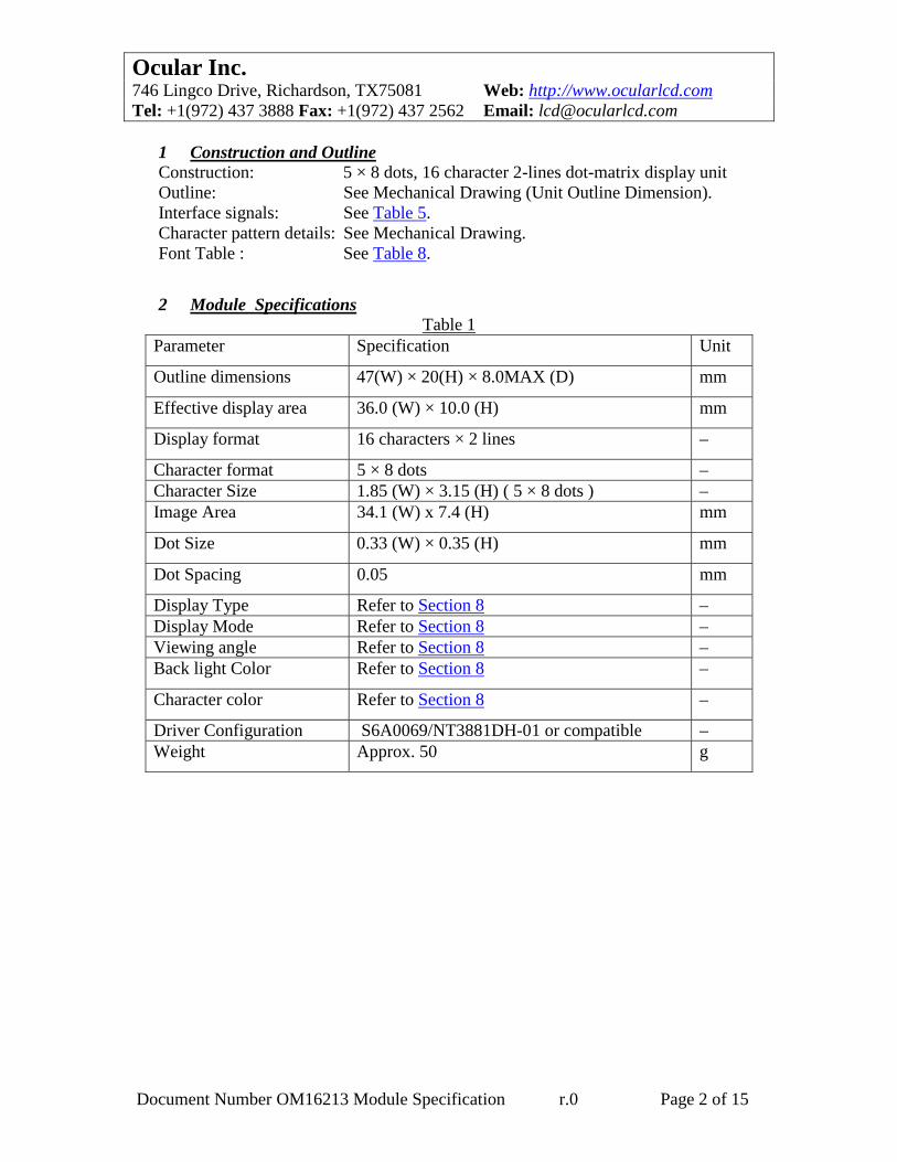
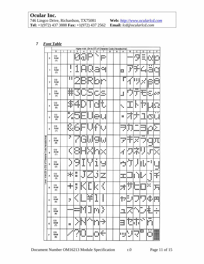
1 Construction and Outline Construction: 5 × 8 dots, 16 character 2-lines dot-matrix display unit Outline: See Mechanical Drawing (Unit Outline Dimension). Interface signals: See Table 5. Character pattern details: See Mechanical Drawing. Font Table : See Table 8. 2 Module Specifications
Table 1 Parameter Specification Unit
Outline dimensions 47(W) × 20(H) × 8.0MAX (D) mm
Effective display area 36.0 (W) × 10.0 (H) mm
Display format 16 characters × 2 lines –
Character format 5 × 8 dots – Character Size 1.85 (W) × 3.15 (H) ( 5 × 8 dots ) – Image Area 34.1 (W) x 7.4 (H) mm
Dot Size 0.33 (W) × 0.35 (H) mm
Dot Spacing 0.05 mm
Display Type Refer to Section 8 – Display Mode Refer to Section 8 – Viewing angle Refer to Section 8 – Back light Color Refer to Section 8 –
Character color Refer to Section 8 –
Driver Configuration S6A0069/NT3881DH-01 or compatible – Weight Approx. 50 g
Document Number OM16213 Module Specification r.0 Page 2 of 15

Ocular Inc. 746 Lingco Drive, Richardson, TX75081 Web: http://www.ocularlcd.com Tel: +1(972) 437 3888 Fax: +1(972) 437 2562 Email: [email protected]
3 Electrical Specifications and Electrical Configuration
3.1 Absolute maximum ratings Table 2
Parameter Symbol Min. Max. Unit Remark
Power Supply Voltage VDD - VSS 0 7 V Input Voltage VLC VDD-7.0 VDD V VIN VSS VDD V Operating Temperature Topr 0 50 °C Storage Temperature Tstg -20 60 °C Supply Current ( Backlight LED )
ILED – 60 mA Ta = 25°C
Voltage LED Back light VLED—-
VLED+
– 5 V DC
3.2 Electrical characteristics
Table 3 ( Ta = 25 °C ) Parameter Symbol Min. Typ. Max. Unit Condition
Supply Voltage ( Logic ) VDD-VSS 4.75 5 5.25 V Contrast Voltage
Stnd. Ext.
VDD-V0 VDD-V0
- -
4.7 5.0
- -
V V
Low VIL1 -0.3 – 0.6 V Input Voltage High VIH1 2.2 – VDD V Low VOL1 – – 0.4 V IOL= 1.2 mA Output Voltage High VOH1 2.4 – – V -IOH =0.205mA
Input Leakage Current IIL1 – – 1 µA Internal Oscillating Frequency fOSC 250 kHz
IDD 1.8 2.5 mA VDD=5V, V0=0VSupply Current ILED - 40 mA VLED+-VLED-
=4.2V Supply Voltage (Backlight LED )
VLED+-VLED– 4.2 4.5 V
Document Number OM16213 Module Specification r.0 Page 3 of 15
Ocular Inc. 746 Lingco Drive, Richardson, TX75081 Web: http://www.ocularlcd.com Tel: +1(972) 437 3888 Fax: +1(972) 437 2562 Email: [email protected]
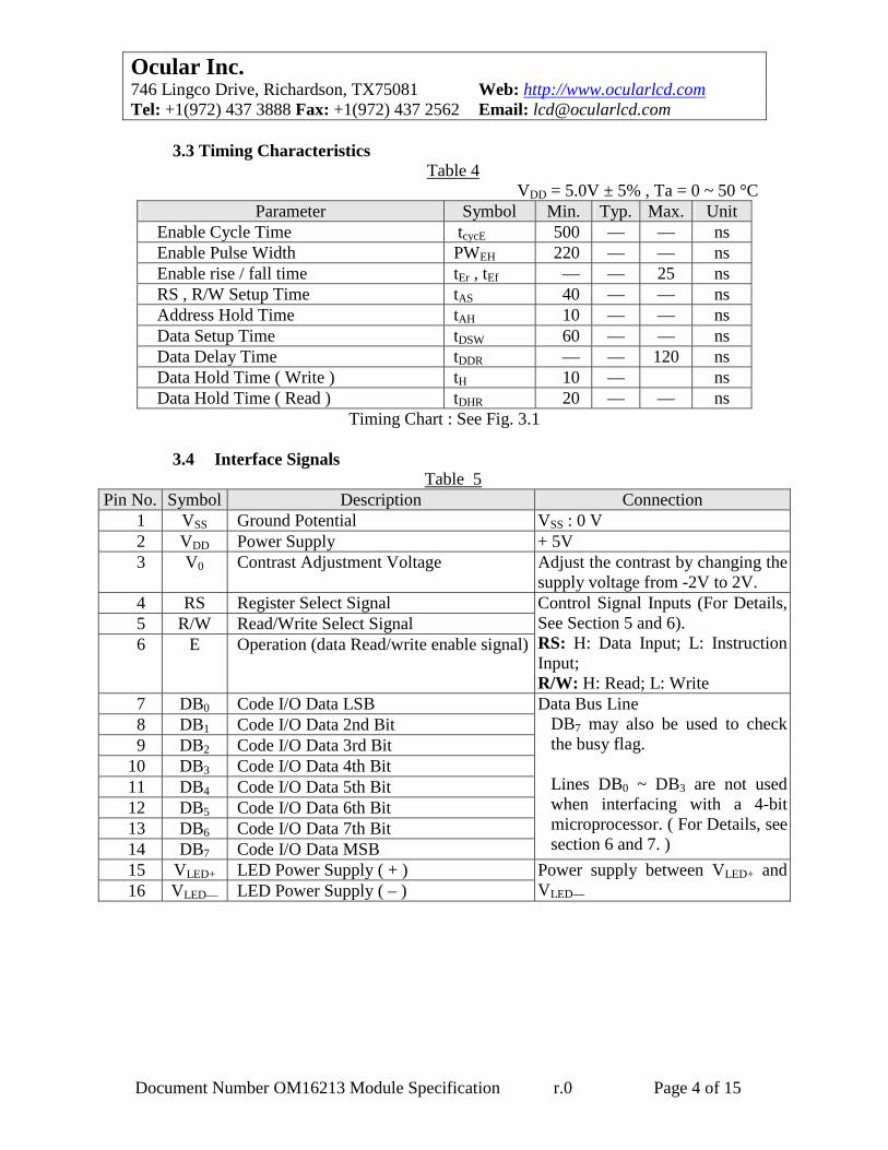
3.3 Timing Characteristics
Table 4 VDD = 5.0V ± 5% , Ta = 0 ~ 50 °C
Parameter Symbol Min. Typ. Max. Unit Enable Cycle Time tcycE 500 — — ns Enable Pulse Width PWEH 220 — — ns Enable rise / fall time tEr , tEf — — 25 ns RS , R/W Setup Time tAS 40 — — ns Address Hold Time tAH 10 — — ns Data Setup Time tDSW 60 — — ns Data Delay Time tDDR — — 120 ns Data Hold Time ( Write ) tH 10 — ns Data Hold Time ( Read ) tDHR 20 — — ns
Timing Chart : See Fig. 3.1
3.4 Interface Signals Table 5
Pin No. Symbol Description Connection 1 VSS Ground Potential VSS : 0 V 2 VDD Power Supply + 5V 3 V0 Contrast Adjustment Voltage Adjust the contrast by changing the
supply voltage from -2V to 2V. 4 RS Register Select Signal 5 R/W Read/Write Select Signal 6 E Operation (data Read/write enable signal)
Control Signal Inputs (For Details, See Section 5 and 6). RS: H: Data Input; L: Instruction Input; R/W: H: Read; L: Write
7 DB0 Code I/O Data LSB 8 DB1 Code I/O Data 2nd Bit 9 DB2 Code I/O Data 3rd Bit
10 DB3 Code I/O Data 4th Bit 11 DB4 Code I/O Data 5th Bit 12 DB5 Code I/O Data 6th Bit 13 DB6 Code I/O Data 7th Bit 14 DB7 Code I/O Data MSB
Data Bus Line DB7 may also be used to check the busy flag. Lines DB0 ~ DB3 are not used when interfacing with a 4-bit microprocessor. ( For Details, see section 6 and 7. )
15 VLED+ LED Power Supply ( + ) 16 VLED— LED Power Supply ( – )
Power supply between VLED+ and VLED—
Document Number OM16213 Module Specification r.0 Page 4 of 15

Ocular Inc. 746 Lingco Drive, Richardson, TX75081 Web: http://www.ocularlcd.com Tel: +1(972) 437 3888 Fax: +1(972) 437 2562 Email: [email protected]
VIH1VIL1
VIH1VIL1
VIH1
VIL1
VIH1
VIL1
tAH
tAH
tEf
VIL1
VIH1VIL1
VIH1VIL1 Valid Data
tcycE
tAS
t Er tDSW tH
VIL1
RS
R/W
E
DB0 to DB7
PW EH
VIL1
Write Operations
VIH1VIL1
VIH1VIL1
VIH1
VIL1
VIH1
VIL1
tAH
tAH
tEf
VIL1
VOH1VOL1
VOH1VOL1 Valid Data
tcycE
tAS
t Er
tDHR
VIH1
RS
R/W
E
DB0 to DB7
PW EH
tDDR
VIH1
Read Operations
Fig. 3.1
Document Number OM16213 Module Specification r.0 Page 5 of 15
Ocular Inc. 746 Lingco Drive, Richardson, TX75081 Web: http://www.ocularlcd.com Tel: +1(972) 437 3888 Fax: +1(972) 437 2562 Email: [email protected]
4 Optical Characteristics
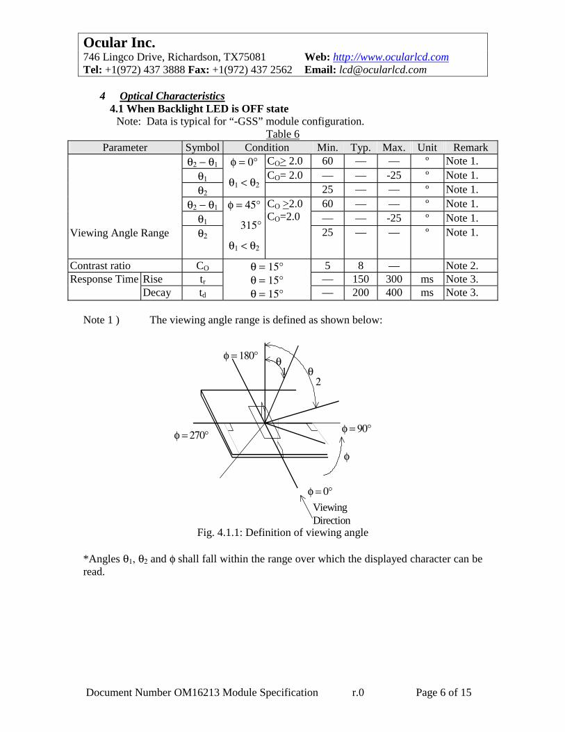
4.1 When Backlight LED is OFF state Note: Data is typical for “-GSS” module configuration.
Table 6 Parameter Symbol Condition Min. Typ. Max. Unit Remark
θ2 − θ1 CO> 2.0 60 — — º Note 1. θ1 CO= 2.0 — — -25 º Note 1. θ2
φ = 0°
θ1 < θ2 25 — — º Note 1. θ2 − θ1 60 — — º Note 1.
θ1 — — -25 º Note 1. Viewing Angle Range θ2
φ = 45°
315°
θ1 < θ2
CO >2.0 CO=2.0
25 — — º Note 1.
Contrast ratio CO 5 8 — Note 2. Rise tr — 150 300 ms Note 3. Response Time Decay td
θ = 15° θ = 15° θ = 15° — 200 400 ms Note 3.
Note 1 ) The viewing angle range is defined as shown below:
θ 1 θ
2
φ = 0°
φ = 90°
φ = 180°
φ = 270°
φ
Viewing Direction
Fig. 4.1.1: Definition of viewing angle *Angles θ1, θ2 and φ shall fall within the range over which the displayed character can be read.
Document Number OM16213 Module Specification r.0 Page 6 of 15

Ocular Inc. 746 Lingco Drive, Richardson, TX75081 Web: http://www.ocularlcd.com Tel: +1(972) 437 3888 Fax: +1(972) 437 2562 Email: [email protected]
Note 2 ) Contrast ratio is defined as follows:
When input signal is applied to the unit to select ( turn on ), the LCD dots ( pixels ) to be measured in the optical characteristics test method as defined in Fig. 3:
Contrast ratio =
Photodetector output voltage with non-selectwaveform being applied
Photodetector output voltage with selectwaveform being applied
Note 3 ) When input signal for selecting or non-selecting the dots to be measured
are applied using the optical characteristics test method shown in Fig. 3. The response characteristics of the photo-detector output are measured as shown in Fig. 4.
Note 4 ) This optical data is specified on condition that the LCD temperature is
25°C. When designing, be sure to check the rating of V0 in table 3. Note 5 ) The response characteristics of photo-detector output are measured as
shown in Fig. 4, assuming that input signals are applied so as to select and deselect the dots to be measured, in the optical characteristics test method shown in Fig. 3.
Note 6 ) Table 6 shows the optical characteristics detected when the LCD applied
voltage waveforms are in the highest frequency *. * The most critical condition for the characteristics of LCD.
ContrastDetector
Response timeDetector
Photo-detector
Viewing sensitivity modul
Lens
LCD panels with polarizer
Laser
θ
Fig. 4.1.2 Optical Characteristics Test Method Document Number OM16213 Module Specification r.0 Page 7 of 15
Ocular Inc. 746 Lingco Drive, Richardson, TX75081 Web: http://www.ocularlcd.com Tel: +1(972) 437 3888 Fax: +1(972) 437 2562 Email: [email protected]
Nonselectwaveform
Select Waveform NonselectWaveform
90%
10%
100%
tr td
Drive Waveform
Response Waveform
0 VoltVoltageAppliedto LCDcell
Photo DetectorOutput
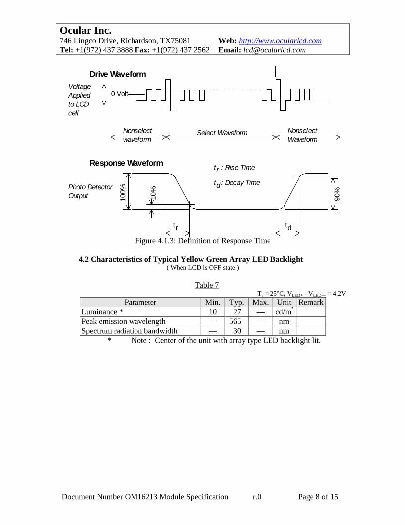
tr : Rise Time
td: Decay Time
Figure 4.1.3: Definition of Response Time
4.2 Characteristics of Typical Yellow Green Array LED Backlight
( When LCD is OFF state )
Table 7 Ta = 25°C, VLED+ - VLED— = 4.2V
Parameter Min. Typ. Max. Unit Remark Luminance * 10 27 — cd/m² Peak emission wavelength — 565 — nm Spectrum radiation bandwidth — 30 — nm
* Note : Center of the unit with array type LED backlight lit.
Document Number OM16213 Module Specification r.0 Page 8 of 15

Ocular Inc. 746 Lingco Drive, Richardson, TX75081 Web: http://www.ocularlcd.com Tel: +1(972) 437 3888 Fax: +1(972) 437 2562 Email: [email protected]
5 Pin Description 1) VDD and VSS Pins VDD and VSS pins are for power supply. VSS pin is grounded, and VDD pin is
supplied with +5V. Each bias voltage necessary to drive LCD is generated in the unit.
2) RS Pin The controller LSI has two 8-bit registers; an instruction register (IR) and a data
register (DR). RS signal selects these registers. IR stores instruction codes such as display clear, shift, etc., and also stores address
information for the display data RAM ( DD RAM ), character generator RAM ( CG RAM ); DR is used for temporarily storing data to be written into DD RAM and CG RAM.
" L " : Instruction register ( when writing ) Busy flag register; address counter ( when reading ). " H " : Data register ( read / write ).
3) R/W Pin Read or write select signal pin. " L " : Writing " H " : Reading 4) E Pin Data read or write operation enable signal pin. 5) DB0 ~ DB7 Pins Data bus with three-state, bidirectional function for use in data transactions with
MPU. DB7 may also be used to check the busy flag. DB0 ~ DB3 are not used when interfacing with a 4-bit microprocessor.
6) V5 Pin Viewing angle is varied and contrast is adjusted by changing voltage between -
2V~ +2V. 7) VLED+ and VLED—
Power supply for LED backlight. ( By changing the supply voltage, backlight luminance can be adjusted. ).
Document Number OM16213 Module Specification r.0 Page 9 of 15

Ocular Inc. 746 Lingco Drive, Richardson, TX75081 Web: http://www.ocularlcd.com Tel: +1(972) 437 3888 Fax: +1(972) 437 2562 Email: [email protected]
6 Instruction Set
Table 8 Code Exec Instruction
RS R/W DB7 DB6 DB5 DB4 DB3 DB2 DB1 DB0
Function Time
Display Clear
0 0 0 0 0 0 0 0 0 1 Clear entire display area, restore display from shift, and load address counter 00H.
1.64ms
Display/ Cursor Home
0 0 0 0 0 0 0 0 1 * Restore display from shift and load address counter with DD RAM address 00H.
1.64ms
Entry Mode Set
0 0 0 0 0 0 0 1 I/D S Specify cursor advance direction and display shift mode. This operation takes place after each data transfer
40 us
Display ON/ OFF
0 0 0 0 0 0 1 D C B Specify activation of display (D), cursor (C), and blinking of character at cursor position (B).
40 us
Display/ Cursor Shift
0 0 0 0 0 1 S/C R/L * * Shift display or move cursor. 40 us
Function Set
0 0 0 0 1 DL 1 0 * * Set interface data length (DL). 40 us
CG RAM Address Set
0 0 0 1 ACG Load the address counter with a CG RAM address. Subsequent data is CG RAM data.
40 us
DDRAM Address Set
0 0 1 ADD Load the address counter with a DD RAM address. Subsequent data is DD RAM data.
40 us
BusyFlag/ Address Counter Read
0 1 BF AC Read Busy Flag (BF) and contents of address counter (AC).
40 us
CG/DD RAM Data Write
1 0 Write Data Write data to CG RAM or DD RAM.
40 us
CG/DD RAM Data Read
1 1 Read Data Read data from CG RAM or DD RAM.
40 us
I/D = 1: Increment; I/D = 0: Decrement; S/C = 1: Shift Display; S/C = 0: Move Cursor; S = 1: Shift Display; S = 0: Freeze Display; R/L = 1: Shift right; R/L = 0: Shift Left; D = 1: Display ON; D = 0: Display Off; DL = 1: 8 bit; DL = 0: 4-bit C = 1: Cursor ON C = 0: Cursor Off; BF = 1: During Internal
Operation BF = 0: End of Internal
Operation; B = 1:Character at cursor
position blinks B = 0:Character at cursor
position unblinks
Document Number OM16213 Module Specification r.0 Page 10 of 15
Ocular Inc. 746 Lingco Drive, Richardson, TX75081 Web: http://www.ocularlcd.com Tel: +1(972) 437 3888 Fax: +1(972) 437 2562 Email: [email protected]
7 Font Table
Document Number OM16213 Module Specification r.0 Page 11 of 15

Ocular Inc. 746 Lingco Drive, Richardson, TX75081 Web: http://www.ocularlcd.com Tel: +1(972) 437 3888 Fax: +1(972) 437 2562 Email: [email protected]
8 Explanation of Part Numbering System
Value-added options
Temperature/ModesStandard temp, positive modeWide temp, positive modeW
S
Viewing Mode (Background/Character)SGNHTB
STN 6 o'clock; Yellow-green/dark blue characterSTN 6 o'clock, Gray/dark blue characterSTN 12 o'clock; Yellow-green/black characterSTN 12 o'clock; Gray/blue characterTN 12 o'clock; Gray/Black CharacterTN 6 o'clock; Gray/black character
Backlight
N NoneModule NumberSeriesNumberNumber of LinesNumber of Characters per lineCharacter Module
G Yellow Green LED (array), transflective
OM16213 x x x x
Note: Not all possible configurations are possible or available for all models. If a specific configuration is required but is not listed as a current configuration, contact Ocular directly for availability.
Document Number OM16213 Module Specification r.0 Page 12 of 15
Ocular Inc. 746 Lingco Drive, Richardson, TX75081 Web: http://www.ocularlcd.com Tel: +1(972) 437 3888 Fax: +1(972) 437 2562 Email: [email protected]
9 Precautions Relating to Product Handling
The following precautions will guide you in handling our product correctly. 1) Liquid crystal display devices
1. The liquid crystal display device panel used in the liquid crystal display module is made of glass. Avoid any strong mechanical shock. If the glass should break, handle it with care.
2. The polarizer on the surface of the LCD is relatively soft. Care must be taken to prevent scratches.
2) Protection of liquid crystal display module against static electricity discharge 1. When working with the module, be sure to ground your body and any
electrical equipment you may be using. We strongly recommend using anti-static mats, to protect worktables against the hazards of electrical shock.
2. We recommend wearing a ESP grounding strap when handling the module. 3. Slowly and carefully remove the protective film from the LCD module, since
this can generate static electricity. 3) When the LCD modules must be stored for long periods of time
1. Protect the modules from high temperatures and humidity. 2. Keep the modules away from direct sunlight or direct exposure to ultraviolet
rays. 4) Use the module with a power supply that is equipped with over current protection
since the module does not employ current limiting protection circuitry. 5) Do not ingest the LCD fluid if it should leak out of a damaged LCD module. If hands
or clothing come in contact with the LCD fluid, wash immediately with soap and water.
6) Conductivity is not guaranteed for models that use metal holders where solder
connections between the metal holder and the PCB are not used. Please contact us to discuss appropriate ways to assure conductivity.
7) For models which use CCFL backlighting:
1. CCFL backlights operate at voltage levels greater than 200 volts. Precautions must be taken to avoid electrical shock.
2. Using CCFL backlighting for extended periods of time at low temperatures will significantly shorten their service life.
8) For models which used touch panels:
1. Do not stack modules because they can be damaged by components on neighboring modules.
2. Do not place heavy objects on top of the product because this can cause the glass to break.
Document Number OM16213 Module Specification r.0 Page 13 of 15

Ocular Inc. 746 Lingco Drive, Richardson, TX75081 Web: http://www.ocularlcd.com Tel: +1(972) 437 3888 Fax: +1(972) 437 2562 Email: [email protected]
9) Models which use flexible cable, heat seal or TAB:
1. In order to maintain reliability, do not touch or hold by the connector area. 2. Avoid bending, pulling, or any other excessive forces, which can result in
broken connectors.
Document Number OM16213 Module Specification r.0 Page 14 of 15

Ocular Inc. 746 Lingco Drive, Richardson, TX75081 Web: http://www.ocularlcd.com Tel: +1(972) 437 3888 Fax: +1(972) 437 2562 Email: [email protected]
Document Number OM16213 Module Specification r.0 Page 15 of 15
10 Mechanical Drawing