odom es3 setup click to edit master title...
TRANSCRIPT

Click to edit Master title style
• Click to edit Master text styles– Second level
• Third level– Fourth level
» Fifth level
1Slide 1
odomhydrographic.com, USA, 225.769.3051
OdomES3 Setup
1
ES3 Hardware Configuration
Click to edit Master title style
• Click to edit Master text styles– Second level
• Third level– Fourth level
» Fifth level
2Slide 2
odomhydrographic.com, USA, 225.769.3051
OdomES3 Setup
2
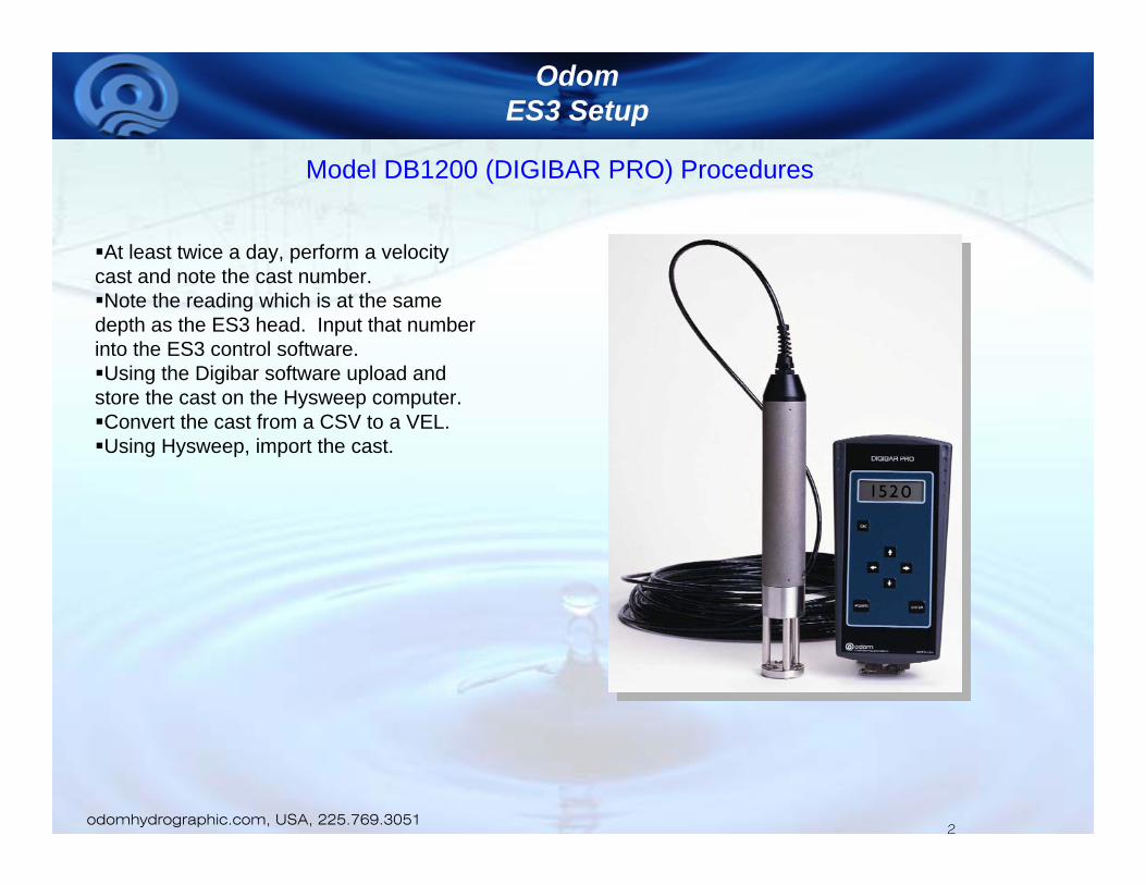
At least twice a day, perform a velocity cast and note the cast number.Note the reading which is at the same
depth as the ES3 head. Input that number into the ES3 control software.Using the Digibar software upload and
store the cast on the Hysweep computer.Convert the cast from a CSV to a VEL.Using Hysweep, import the cast.
Model DB1200 (DIGIBAR PRO) Procedures
Click to edit Master title style
• Click to edit Master text styles– Second level
• Third level– Fourth level
» Fifth level
3Slide 3
odomhydrographic.com, USA, 225.769.3051
OdomES3 Setup
3
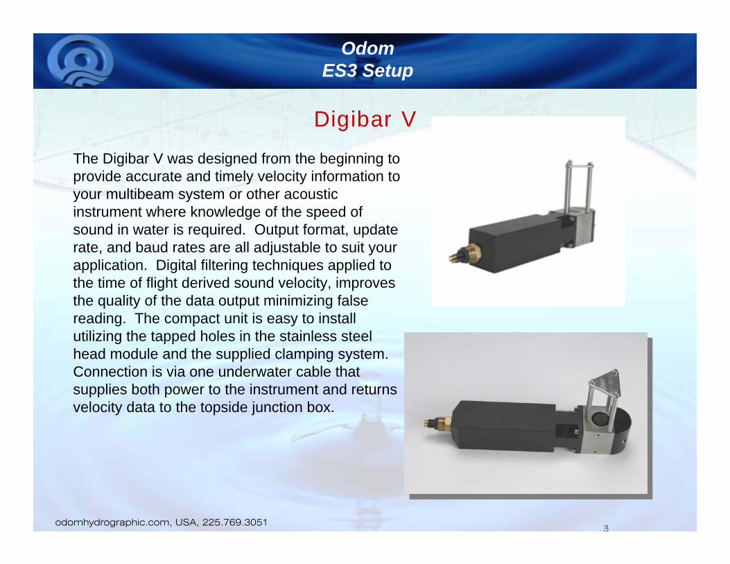
Digibar V
The Digibar V was designed from the beginning to provide accurate and timely velocity information to your multibeam system or other acoustic instrument where knowledge of the speed of sound in water is required. Output format, update rate, and baud rates are all adjustable to suit your application. Digital filtering techniques applied to the time of flight derived sound velocity, improves the quality of the data output minimizing false reading. The compact unit is easy to install utilizing the tapped holes in the stainless steel head module and the supplied clamping system. Connection is via one underwater cable that supplies both power to the instrument and returns velocity data to the topside junction box.
Click to edit Master title style
• Click to edit Master text styles– Second level
• Third level– Fourth level
» Fifth level
4Slide 4
odomhydrographic.com, USA, 225.769.3051
OdomES3 Setup
4
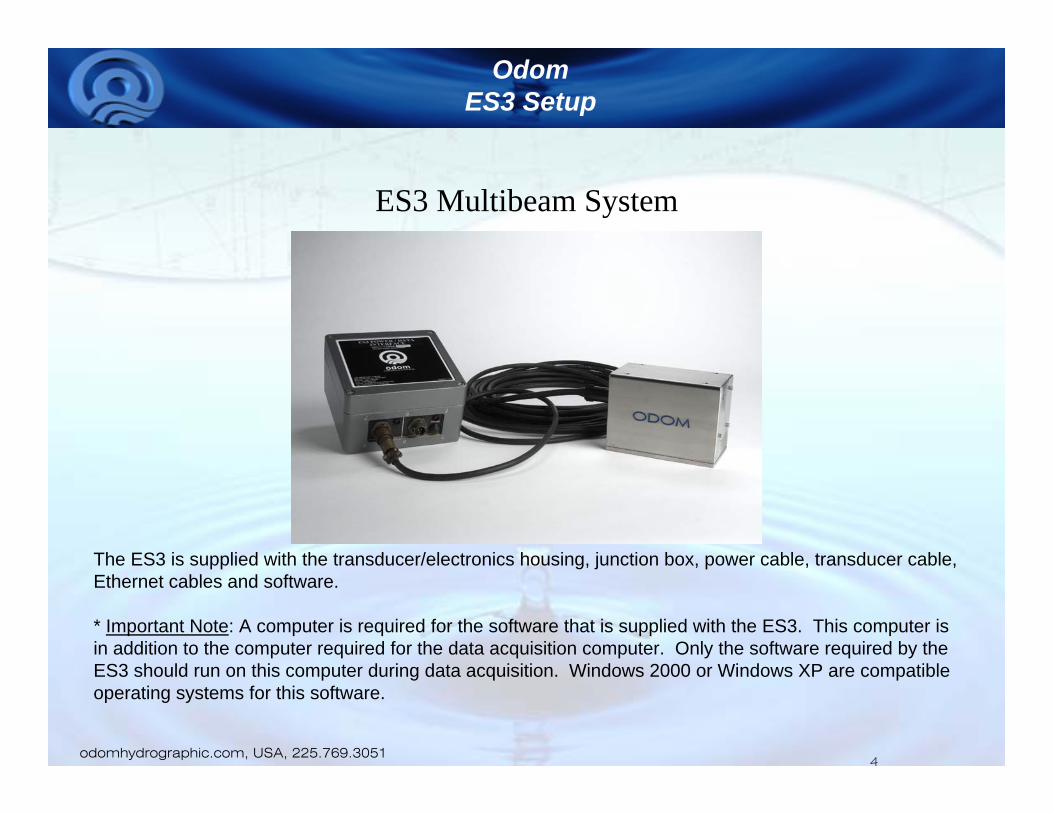
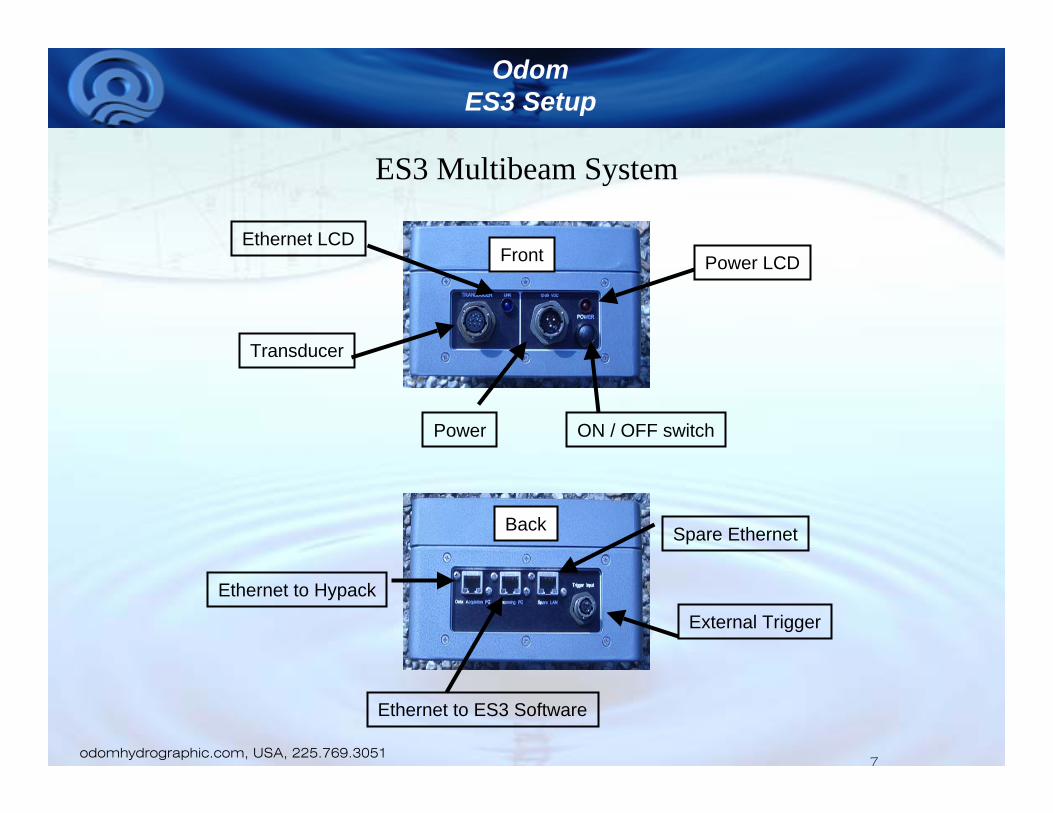
ES3 Multibeam System
The ES3 is supplied with the transducer/electronics housing, junction box, power cable, transducer cable, Ethernet cables and software.
* Important Note: A computer is required for the software that is supplied with the ES3. This computer is in addition to the computer required for the data acquisition computer. Only the software required by the ES3 should run on this computer during data acquisition. Windows 2000 or Windows XP are compatible operating systems for this software.
Click to edit Master title style
• Click to edit Master text styles– Second level
• Third level– Fourth level
» Fifth level
5Slide 5
odomhydrographic.com, USA, 225.769.3051
OdomES3 Setup
5
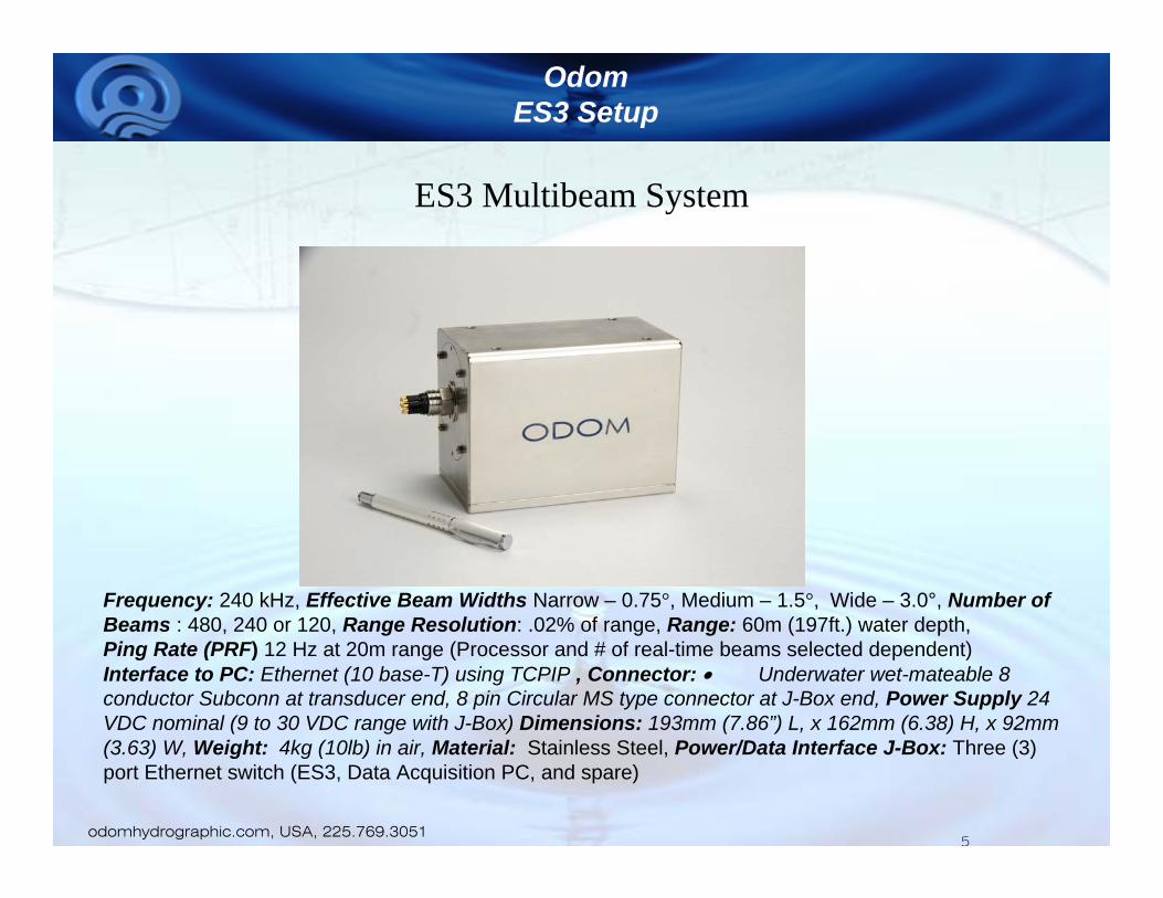
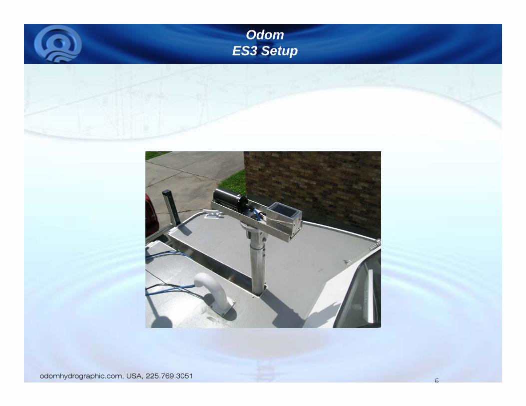
ES3 Multibeam System
Frequency: 240 kHz, Effective Beam Widths Narrow – 0.75°, Medium – 1.5°, Wide – 3.0°, Number of Beams : 480, 240 or 120, Range Resolution: .02% of range, Range: 60m (197ft.) water depth, Ping Rate (PRF) 12 Hz at 20m range (Processor and # of real-time beams selected dependent) Interface to PC: Ethernet (10 base-T) using TCPIP , Connector: • Underwater wet-mateable 8 conductor Subconn at transducer end, 8 pin Circular MS type connector at J-Box end, Power Supply 24 VDC nominal (9 to 30 VDC range with J-Box) Dimensions: 193mm (7.86”) L, x 162mm (6.38) H, x 92mm (3.63) W, Weight: 4kg (10lb) in air, Material: Stainless Steel, Power/Data Interface J-Box: Three (3) port Ethernet switch (ES3, Data Acquisition PC, and spare)
Click to edit Master title style
• Click to edit Master text styles– Second level
• Third level– Fourth level
» Fifth level
6Slide 6
odomhydrographic.com, USA, 225.769.3051
OdomES3 Setup
6
Click to edit Master title style
• Click to edit Master text styles– Second level
• Third level– Fourth level
» Fifth level
7Slide 7
odomhydrographic.com, USA, 225.769.3051
OdomES3 Setup
7
ES3 Multibeam System
Transducer
Power
Ethernet to Hypack
Ethernet to ES3 Software
Front
Back
ON / OFF switch
Spare Ethernet
Power LCDEthernet LCD
External Trigger

Click to edit Master title style
• Click to edit Master text styles– Second level
• Third level– Fourth level
» Fifth level
8Slide 8
odomhydrographic.com, USA, 225.769.3051
OdomES3 Setup
8
Odom Junction Box
Hemisphere VS110Heading
DMS-25 Heave Compensator
Desktop Hysweep Computer
ES3 Transducer ES3 Power Data Interface ES3 Laptop containing Control Software
Position only
Roll data
DGPSDATA
Ethernet Interface
Ethernet Interface
Position, HPR &Heading
Data from Digibar V
Click to edit Master title style
• Click to edit Master text styles– Second level
• Third level– Fourth level
» Fifth level
9Slide 9
odomhydrographic.com, USA, 225.769.3051
OdomES3 Setup
9
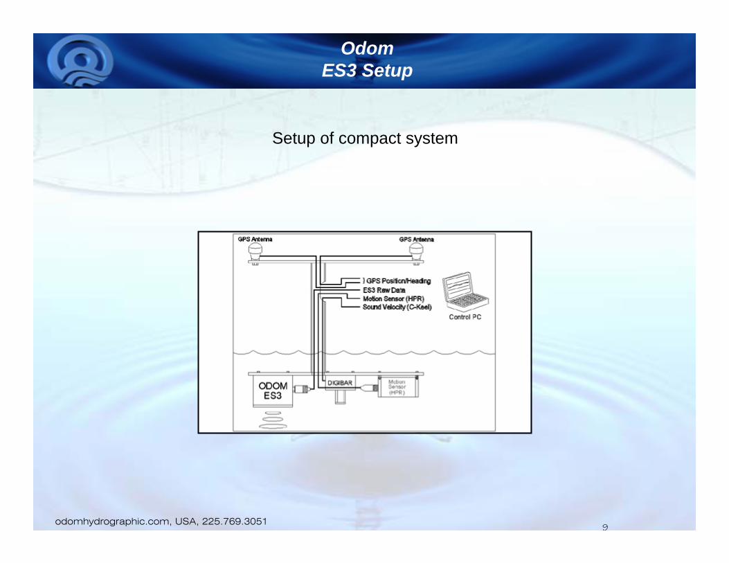
Setup of compact system
Click to edit Master title style
• Click to edit Master text styles– Second level
• Third level– Fourth level
» Fifth level
10Slide 10
odomhydrographic.com, USA, 225.769.3051
OdomES3 Setup
10
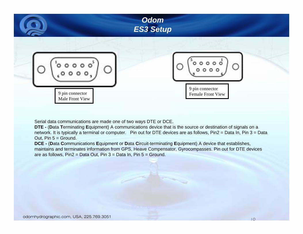
9 pin connectorMale Front View
1 5
6 9
9 pin connectorFemale Front View
15
69
Serial data communications are made one of two ways DTE or DCE. DTE - (Data Terminating Equipment) A communications device that is the source or destination of signals on a network. It is typically a terminal or computer. Pin out for DTE devices are as follows, Pin2 = Data In, Pin 3 = Data Out, Pin 5 = Ground.DCE - (Data Communications Equipment or Data Circuit-terminating Equipment) A device that establishes, maintains and terminates information from GPS, Heave Compensator, Gyrocompasses. Pin out for DTE devices are as follows, Pin2 = Data Out, Pin 3 = Data In, Pin 5 = Ground.
Back to Flowchart

Click to edit Master title style
• Click to edit Master text styles– Second level
• Third level– Fourth level
» Fifth level
11Slide 11
odomhydrographic.com, USA, 225.769.3051
OdomES3 Setup
11
Basic information concerning Ethernet cables
•A straight-thru cable has identical ends. •A crossover cable has different ends. •A straight-thru is used as a patch cord in Ethernet connections. •A crossover is used to connect two Ethernet devices without a hub or for connecting two hubs. •A crossover has one end with the Orange set of wires switched with the Green set. •Odd numbered pins are always striped, even numbered pins are always solid colored. •Looking at the RJ-45 with the clip facing away from you, Brown is always on the right, and pin 1 is on the left. •No more than 1/2" of the Ethernet cable should be untwisted otherwise it will be susceptible to crosstalk. •Do not deform, do not bend, do not stretch, do not staple, do not run parallel with power cables, and do not run Ethernet cables near noise inducing components.
Back to Flowchart
Click to edit Master title style
• Click to edit Master text styles– Second level
• Third level– Fourth level
» Fifth level
12Slide 12
odomhydrographic.com, USA, 225.769.3051
OdomES3 Setup
12
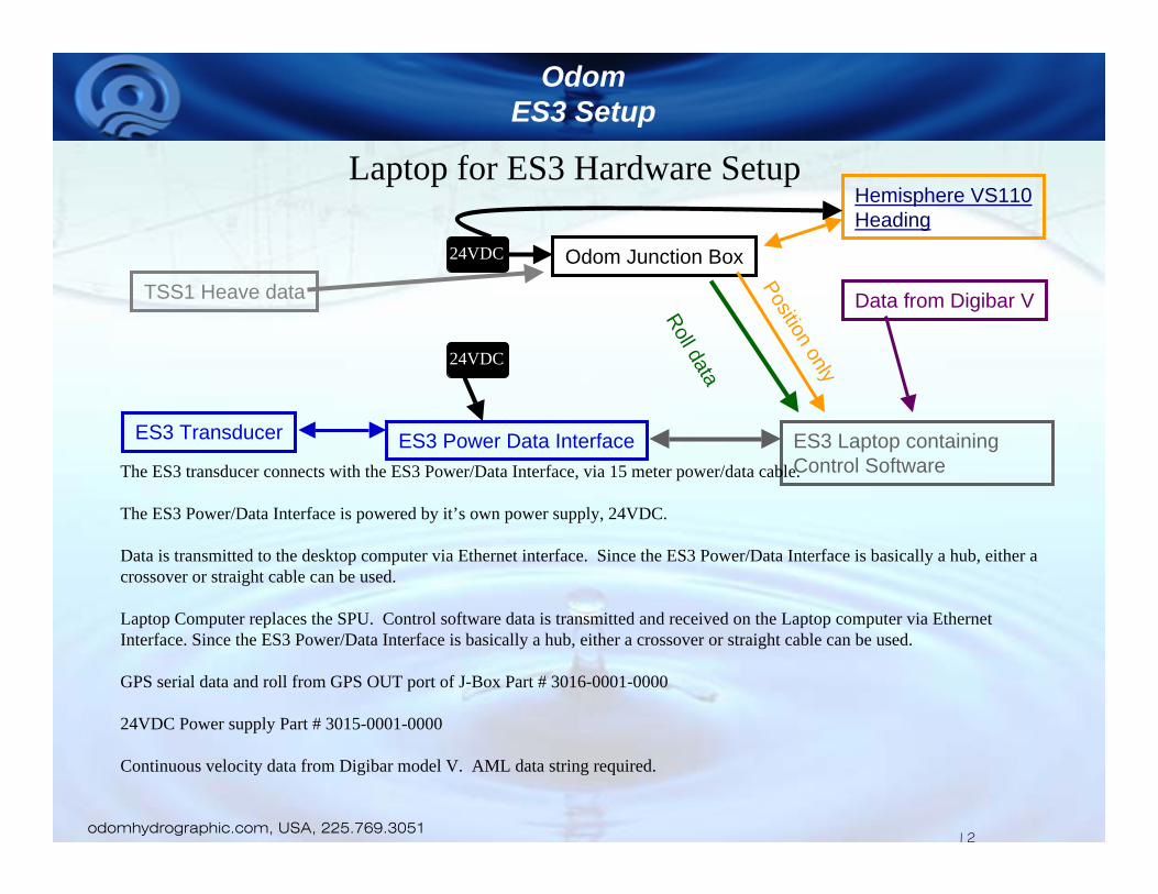
Laptop for ES3 Hardware Setup
Odom Junction Box
Hemisphere VS110Heading
ES3 Transducer ES3 Power Data Interface ES3 Laptop containing Control Software
Position only
The ES3 transducer connects with the ES3 Power/Data Interface, via 15 meter power/data cable.
The ES3 Power/Data Interface is powered by it’s own power supply, 24VDC.
Data is transmitted to the desktop computer via Ethernet interface. Since the ES3 Power/Data Interface is basically a hub, either a crossover or straight cable can be used.
Laptop Computer replaces the SPU. Control software data is transmitted and received on the Laptop computer via Ethernet Interface. Since the ES3 Power/Data Interface is basically a hub, either a crossover or straight cable can be used.
GPS serial data and roll from GPS OUT port of J-Box Part # 3016-0001-0000
24VDC Power supply Part # 3015-0001-0000
Continuous velocity data from Digibar model V. AML data string required.
24VDC
24VDC
Roll data
TSS1 Heave data Data from Digibar V

Click to edit Master title style
• Click to edit Master text styles– Second level
• Third level– Fourth level
» Fifth level
13Slide 13
odomhydrographic.com, USA, 225.769.3051
OdomES3 Setup
13
Desktop Computer operates with 110VAC. The requirements for the user supplied PC are: Windows XP, an available Ethernet port, and at least 2 GHz Pentium IV processor. Standard software screen resolution is 1024x768.
Hypack Hysweep software module (USB Hardlock key required).
Interfaces to ES3 Power/Data Interface via Ethernet connection using a crossover cable, part # 2300-0053-0000.The sonar head needs to run with a static IP (Internet Protocol) address for both head and PC. The IP address of the PC must beset to 192.168.0.X (X can be any number between 3 and 255). Also set the subnet mask to 255.255.255.0. These settings can be found in the ‘Network Connections’ menu under ‘Settings’ in the ‘Start’ menu, then click on properties of the LAN adapter, and properties of the TCP/IP. There is also a settings box for default gateway, but it can be left blank. For troubleshooting purposes you may need to know that the sonar head has IP address 192.168.0.2.
All serial ports are DTE and male 9 pin connectors.
Serial port1 is used “if needed” to communicate directly to the RTK GPS for system setup.
Serial port 2 connects to the GPS I/O port of the J-Box. Data strings GGK, GGA, VTG & ZDA. Baud rate = 9600, Parity = N, Stop bits = 1, word size = 8. Use DCE to DTE cable # 2300-0045-0000.
Serial port 3 connects to HEADING OUT port of the J-Box. DCE to DTE cable # 2300-0045-0000.
Serial port 4 connects to HEAVE I/O port of the J-Box. DCE to DTE cable # 2300-0045-0000.
Three remote display computer monitors provide information to operations and helmsmen.
Desktop computer operating Hypack/Hysweep

Click to edit Master title style
• Click to edit Master text styles– Second level
• Third level– Fourth level
» Fifth level
14Slide 14
odomhydrographic.com, USA, 225.769.3051
OdomES3 Setup
14
J-Box Part # 3016-0001-0000 (back view)
AUX. HEAVE OUT
HEAVE I/O
HEADING OUT
HEADING I/O
GPS OUT
GPS I/OGPS RX
AUX port is extra, not wired and generally never used.
GPS OUT (9 pin female connector) port sends data to the computer operating the ES3 Control software. Use a DCE to DTE cable # 2300-0045-0000.
HEADING OUT (9 pin female connector) port sends heading data to the computer operating Hysweep. DCE to DTE cable # 2300-0045-0000.
HEAVE OUT (9 pin female connector) port sends roll data to the computer operating ES3 Control Software. DCE to DTE cable # 2300-0045-0000.
GPS RX (9 pin male connector) port is where the interface of serial data is made from the RTK GPS. This is where the J-Box gets GPS feed and is used to assist the heave, and is routed to other ports for data output. This connector is wired as a DTE device.
GPS I/O (9 pin female connector) port sends GPS data to the computer operating Hysweep. data strings GGK, GGA, VTG & ZDA. Baud rate = 9600, Parity = N, Stop bits = 1, word size = 8. DCE to DTE cable # 2300-0045-0000.
HEADING I/O is connected to Port B of the Crescent VS110 GPS.
HEAVE I/O (9 pin female connector) port sends heave, pitch & roll data to the computer operating Hysweep. DCE to DTE cable # 2300-0045-0000.
Click to edit Master title style
• Click to edit Master text styles– Second level
• Third level– Fourth level
» Fifth level
15Slide 15
odomhydrographic.com, USA, 225.769.3051
OdomES3 Setup
15
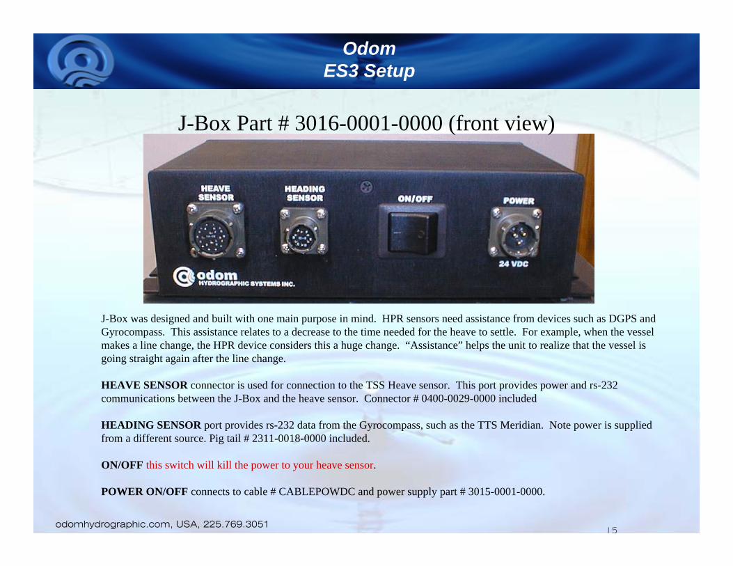
J-Box Part # 3016-0001-0000 (front view)
J-Box was designed and built with one main purpose in mind. HPR sensors need assistance from devices such as DGPS and Gyrocompass. This assistance relates to a decrease to the time needed for the heave to settle. For example, when the vessel makes a line change, the HPR device considers this a huge change. “Assistance” helps the unit to realize that the vessel is going straight again after the line change.
HEAVE SENSOR connector is used for connection to the TSS Heave sensor. This port provides power and rs-232 communications between the J-Box and the heave sensor. Connector # 0400-0029-0000 included
HEADING SENSOR port provides rs-232 data from the Gyrocompass, such as the TTS Meridian. Note power is supplied from a different source. Pig tail # 2311-0018-0000 included.
ON/OFF this switch will kill the power to your heave sensor.
POWER ON/OFF connects to cable # CABLEPOWDC and power supply part # 3015-0001-0000.
Click to edit Master title style
• Click to edit Master text styles– Second level
• Third level– Fourth level
» Fifth level
16Slide 16
odomhydrographic.com, USA, 225.769.3051
OdomES3 Setup
16
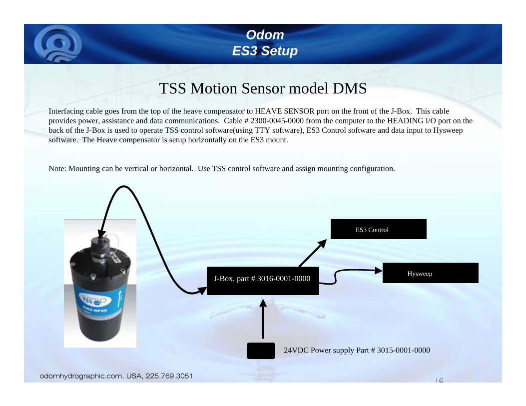
TSS Motion Sensor model DMSInterfacing cable goes from the top of the heave compensator to HEAVE SENSOR port on the front of the J-Box. This cable provides power, assistance and data communications. Cable # 2300-0045-0000 from the computer to the HEADING I/O port on the back of the J-Box is used to operate TSS control software(using TTY software), ES3 Control software and data input to Hysweep software. The Heave compensator is setup horizontally on the ES3 mount.
Note: Mounting can be vertical or horizontal. Use TSS control software and assign mounting configuration.
J-Box, part # 3016-0001-0000.
24VDC Power supply Part # 3015-0001-0000
Hysweep
ES3 Control

Click to edit Master title style
• Click to edit Master text styles– Second level
• Third level– Fourth level
» Fifth level
17Slide 17
odomhydrographic.com, USA, 225.769.3051
OdomES3 Setup
17
TSS Motion Sensor model DMS wiring configuration.Connector (part # 0400-0029-0000) for Motion Sensor.
The Motion Sensor connector is a 12 pin connector. This wiring information applies if you have the Blue TSS cable for a TSS HPR sensor.
This connector fits very tightly. Remove the existing piece of shrink from the TSS cable.Install the bottom part of the connector assembly on the cable.A 2” long by ½” wide tubing on the outside of the cable itself this will keep the bundle together.Cut outer jacket to where 1 3/4” of wire is exposed.The outside shield of the blue cable is the only shield that will be used.Remove all black shrink tubing.Open all wire pairs and remove unneeded wires.Add shrink tubing as needed on solder connections.Wires should be 1” long and connector will fit properly.
Continued
Click to edit Master title style
• Click to edit Master text styles– Second level
• Third level– Fourth level
» Fifth level
18Slide 18
odomhydrographic.com, USA, 225.769.3051
OdomES3 Setup
18
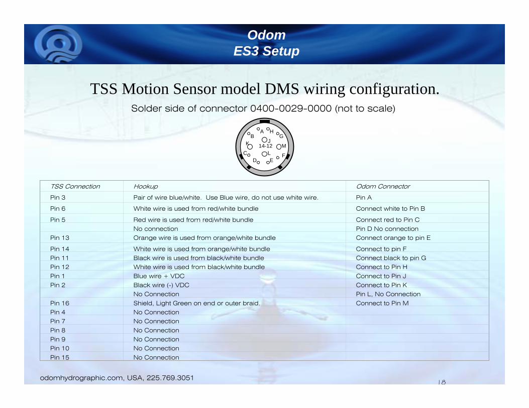
TSS Motion Sensor model DMS wiring configuration.Solder side of connector 0400-0029-0000 (not to scale)
D
BA H
EC
14-12
G
F
K
LM
J
TSS Connection Hookup Odom Connector
Pin 3 Pair of wire blue/white. Use Blue wire, do not use white wire. Pin A
Pin 6 White wire is used from red/white bundle Connect white to Pin B
Pin 5 Red wire is used from red/white bundle Connect red to Pin C
No connection Pin D No connection
Pin 13 Orange wire is used from orange/white bundle Connect orange to pin E
Pin 14 White wire is used from orange/white bundle Connect to pin F
Pin 11 Black wire is used from black/white bundle Connect black to pin G
Pin 12 White wire is used from black/white bundle Connect to Pin H
Pin 1 Blue wire + VDC Connect to Pin J
Pin 2 Black wire (-) VDC Connect to Pin K
No Connection Pin L, No Connection
Pin 16 Shield, Light Green on end or outer braid. Connect to Pin M
Pin 4 No Connection
Pin 7 No Connection
Pin 8 No Connection
Pin 9 No Connection
Pin 10 No Connection
Pin 15 No Connection

Click to edit Master title style
• Click to edit Master text styles– Second level
• Third level– Fourth level
» Fifth level
19Slide 19
odomhydrographic.com, USA, 225.769.3051
OdomES3 Setup
19
Crescent VS110 The Crescent VS110 provides heading and position data. Submeter accuracy provided with Differential options including SBAS (WAAS, EGNOS, etc.) and beacon differential.
Port A connects to the GPS RX connector on the J-Box. Use port A for communications setup. This port is setup for position.Port B is setup for Heading output at 10Hz. Connect to the HEADING I/O port of the J-Box.
Connect the power cable to the same power supply the is used for the J-Box.