defrost.irdefrost.ir/wp-content/uploads/2016/07/سرویس... · 2016-07-02 · westpoint r410a...
TRANSCRIPT

Commercial Air Conditioning ROOFTOP UNIT

Contents
1. Product Lineup
2. External Appearance
3. Nomenclature
4. Features
5. Specifications
6. Dimensional Drawings
7. Wiring Diagrams
8. Electrical Data
9. Fan performance data
10. Refrigerant Cycle Diagram
11. Operation Limit
12. Installation
13. Wired Controller
14. Error Code
15. Accessories
16. Maintenance and Upkeep
※ Manufacture reserves the right to discontinue, or change at any time, specifications or designs without notices and without incurring obligations.

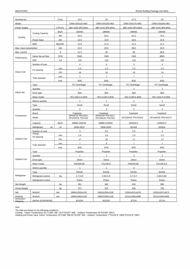
WESTPOINT R410A Rooftop Package Unit 50Hz
1. Product Lineup
Tropical application
Nominal ton
6.2
7.5
8.5
10
12.5
15
17.5
20
25
30
Model
CRM-OSS062.CB3
CRM-OSS075.CB3
CRM-OSS085.CB3
CRM-OSS0100.CB3
CRM-OSS0125.CB3
CRM-OSS0150.CB3
CRM-OSS0175.CB3
CRM-OSS0200.CB3
CRM-OSS0250.CB3
CRM-OSS0300.CB3
Function
Cooling only
Cooling only
Cooling only
Cooling only
Cooling only
Cooling only
Cooling only
Cooling only
Cooling only
Cooling only
Air Outlet
Side air supply
Side air supply
Side air supply
Side air supply
Side air supply
Side air supply
Side air supply
Side air supply
Side air supply
Side air supply
Power Supply
380~415V-3N-50Hz
380~415V-3N-50Hz
380~415V-3N-50Hz
380~415V-3N-50Hz
380~415V-3N-50Hz
380~415V-3N-50Hz
380~415V-3N-50Hz
380~415V-3N-50Hz
380~415V-3N-50Hz
380~415V-3N-50Hz
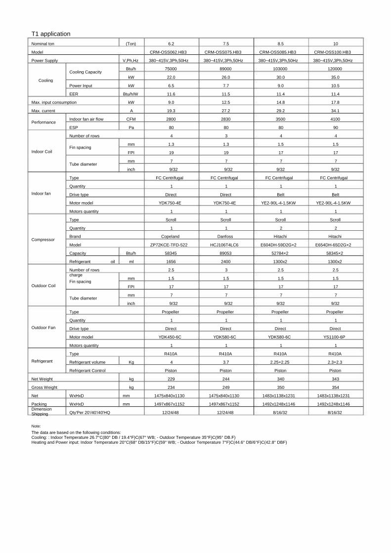
T1 application
Nominal ton
6.2
7.5
8.5
10
12.5
15
17.5
20
Model
CRM-OSS062.HB3
CRM-OSS075.HB3
CRM-OSS085.HB3
CRM-OSS100.HB3
CRM-OSS125.HB3
CRM-OSS150.HB3
CRM-OSS175.HB3
CRM-OSS200.HB3
Function
Heat pump
Heat pump
Heat pump
Heat pump
Heat pump
Heat pump
Heat pump
Heat pump
Air Outlet
Side air supply
Side air supply
Side air supply
Side air supply
Side air supply
Side air supply
Side air supply
Side air supply
Power Supply
380~415V-3N-50Hz
380~415V-3N-50Hz
380~415V-3N-50Hz
380~415V-3N-50Hz
380~415V-3N-50Hz
380~415V-3N-50Hz
380~415V-3N-50Hz
380~415V-3N-50Hz
Note:Please refer to specification tables for accurate cooling or heating capacity with Kw or Btu/h unit.

2
2. External Appearance
6.2&7.5Ton 8.5&10Ton
17.5&20Ton
25&30Ton
12.5&15Ton

WESTPOINT R410A Rooftop Package Unit 50Hz
3. Nomenclature
C R M-O S S 062.C B 3
Power supply R: 380~415V,3Ph,50Hz
Refrigerate type B :R410A
Function mode C:Cooling only H:Electric heater and cooling
Cooling capacity XXX: ton (6.2ton) XX:1000Btu/h S: Side air supply
S : Scroll compressor
O : outdoor unit
Rooftop package
Commercial WESTPOINT

4. Features
4.1 High reliability and high efficiency Outstanding reliability WESTPOINT rooftop package units shall be factory assembled, internally wired, fully charged refrigerant and
100% run tested to check cooling and heating operation, fan and blower rotation, and control sequence before leaving the factory. Wiring internal to the unit shall be colored and numbered for simplified identification. The unit is provided with an integral weather resistant control panel. Multiple self-protecting functions guarantee the safety of unit and running perfectly: high-pressure protection, low-pressure protection, over-heat protection, over-current protection and so on.
Reliable components Famous brand compressor, high IP class motor, reliable pressure switch.
Excellent efficiency
High efficiency scroll compressor; Enlarge the air inlet area space contribute a high efficiency.
Durable construction
Pre-painted exterior cabinet panels pass 1000-hour Salt Spray Test for durability. Weather-resistant construction with capped seams and sloped top panels. G90 galvanized heavy gauge plate conforming to ASTM-A-653, Zinc content of galvanized plate is 275 g/m2.
New fan duct design Optimized fan vane shape reduces pressure loss and im proves heat exchange efficiency.

WESTPOINT R410A Rooftop Package Unit 50Hz
Adjustable Pulley Through changing the working pitch diameter of the pulley mounted
on driver shaft, in turn the revolutions per minute of the driven shaft will increase or decrease to change air volume.
Well compressor control Compressor start-stop is controlled directly by the main control board. To
prevent compressor start and stop frequently, when the unit first / re-power, the compressor will delay three minutes to start, when the indoor temperature is below the set temperature or mode conversion or system protection, the compressor will start after seven minutes delay. It has two-stage control for the system which has two compressors. The system will shut off one compressor in condition of part load.
Compressor cycle duty operation When the set temperature and ambient temperature meet one compressor to
start, for the first time to open compressor A, compressor B start next time, this extends the compressor's life span effectively.
4.2 Easy installation and service Design flexibility, easy to install
New structure design, compact design, smaller body size, reduce transfer cost.; Rooftop or ground is selectable to install. Anywhere removable as requirement without fixed.
Easy drainage External drainage port reserved, quickly and accurately connect the rubber
drainage pipe.
External pressure gauge ports The unit provide external pressure gauge ports, for convenient and fast
checking without remove the panel.
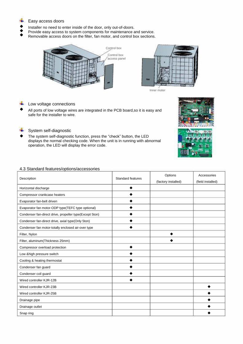
Easy access doors
Installer no need to enter inside of the door, only out-of-doors. Provide easy access to system components for maintenance and service. Removable access doors on the filter, fan motor, and control box sections.
Control box
Control box access panel
Inner moter
Low voltage connections All ports of low voltage wires are integrated in the PCB board,so it is easy and
safe for the installer to wire.
System self-diagnostic The system self-diagnostic function, press the “check” button, the LED
displays the normal checking code. When the unit is in running with abnormal operation, the LED will display the error code.
4.3 Standard features/options/accessories
Description
Horizontal discharge Compressor crankcase heaters Evaporator fan-belt driven Evaporator fan motor-ODP type(TEFC type optional) Condenser fan-direct drive, propeller type(Except 5ton) Condenser fan-direct drive, axial type(Only 5ton) Condenser fan motor-totally enclosed air-over type Filter, Nylon Filter, aluminum(Thickness 25mm) Compressor overload protection Low &high pressure switch Cooling & heating thermostat Condenser fan guard Condenser coil guard Wired controller KJR-12B Wired controller KJR-23B Wired controller KJR-25B Drainage pipe Drainage outlet Snap ring
◆ ◆ ◆ ◆ ◆ ◆
◆ ◆ ◆ ◆ ◆
Standard features
◆ ◆ ◆ ◆ ◆ ◆ ◆
◆ ◆
Options (factory installed)
Accessories (field installed)

WESTPOINT R410A Rooftop Package Unit 50Hz
5. Specifications
Tropical application Nominal ton Model Power Supply
Cooling Capacity (1) Cooling
Power Input (1) EER (1)
Cooling Capacity (2) 46C Cooling
Power Input (2) EER (2)
Max. input consumption Max. current
Performance Indoor fan air flow ESP Number of rows
Fin spacing Indoor Coil
Tube diameter
Type Quantity
Indoor fan Drive type Motor model Motors quantity Type Quantity
Compressor Brand Model Capacity Refrigerant oil charge Number of rows
Fin spacing Outdoor Coil
Tube diameter
Type Quantity
Outdoor Fan Drive type Motor model Motors quantity Type
Refrigerant Refrigerant volume Refrigerant Control
Net Weight Gross Weight Net Dimension Packing Shipping
Note:
WxHxD WxHxD Qty'Per 20'/40'/40'HQ
kg kg
mm mm
kg
mm FPI mm inch
Btu/h ml
mm FPI mm inch
V,Ph,Hz Btu/h kW kW
Btu/h/W Btu/h kW kW
Btu/h/W kW A
CFM Pa
(Ton) 6.2 CRM-OSS062.CB3
380~415V,3Ph,50Hz 75000 22.0 6.5
11.6 61400 18.0 7.7 8.0 9.0
19.3 2800
80 4
1.3 19 7 9/32
FC Centrifugal 1
Direct YDK750-4E
1 Scroll
1 Copeland
ZP72KCE-TFD-522 58345 1656 2.5 1.5 17 7 9/32
Propeller 1
Direct YDK450-6C
1 R410A
4 Piston
223 228
1475x840x1130 1497x867x1152
12/24/48
7.5 CRM-OSS075.CB3 380~415V,3Ph,50Hz
89000 26.0 7.7
11.5 69600 20.4 8.7 8.0
12.5 27.2 2830
80 3
1.3 19 7 9/32
FC Centrifugal 1
Direct YDK750-4E
1 Scroll
1 Danfoss
HCJ106T4LC6 89053 2400
3 1.5 17 7 9/32
Propeller 1
Direct YDK580-6C
1 R410A
3.7 Piston
231 236
1475x840x1130 1497x867x1152
12/24/48
8.5 CRM-OSS085.CB3
380~415V,3Ph,50Hz 103000
30.0 9.0
11.4 80700 23.7 10.1 8.0
14.8 29.2 3500
80 4
1.5 17 7
9/32 FC Centrifugal
1 Belt
YE2-90L-4-1.5KW 1
Scroll 2
Hitachi E604DH-59D2G×2
52784×2 1300x2
2.5 1.5 17 7
9/32 Propeller
1 Direct
YDK580-6C 1
R410A 2.25+2.25
Piston 331 342
1483x1138x1231 1492x1248x1146
8/16/32
10 CRM-OSS0100.CB3
380~415V,3Ph,50Hz 120000
35.0 10.5 11.4
100200 29.4 12.5 8.0
17.8 34.1 4100
90 4
1.5 17 7
9/32 FC Centrifugal
1 Belt
YE2-90L-4-1.5KW 1
Scroll 2
Hitachi E654DH-65D2G×2
58345×2 1300x2
2.5 1.5 17 7
9/32 Propeller
1 Direct
YS1100-6P 1
R410A 2.3+2.3 Piston
335 346
1483x1138x1231 1492x1248x1146
8/16/32
The data are based on the following conditions: Cooling: (1): Indoor Temperature 26.7°C(80° DB / 19.4°F)C(67° WB; - Outdoor Temperature 35°F)C(95° DB.F) (2): Indoor Temperature 26.7°C(80° DB / 19.4°F)C(67° WB; - Outdoor Temperature 46°F)C(115° DB.F)

Nominal ton Model Power Supply
Cooling Capacity (1) Cooling
Power Input (1) EER (1) Cooling Capacity (2)
Cooling 46C Power Input (2) EER (2)
Max. input consumption Max. current
Performance Indoor fan air flow ESP Number of rows
Indoor Coil Fin spacing
Tube diameter
Type Quantity
Indoor fan Drive type Motor model Motors quantity Type Quantity
Compressor Brand Model Capacity Refrigerant oil charge Number of rows
Outdoor Coil Fin spacing
Tube diameter
Type Quantity
Outdoor Fan Drive type Motor model Motors quantity Type
Refrigerant Refrigerant volume Refrigerant Control
Net Weight Gross Weight Net Dimension Packing Shipping
Note:
(Ton)
V,Ph,Hz Btu/h kW kW
Btu/h/W Btu/h kW kW
Btu/h/W kW A
CFM Pa
mm FPI mm inch
12.5 CRM-OSS0125.CB3
380~415V,3Ph,50Hz 150000
43.0 13.0 11.5
125400 36.8 15.9 7.9
21.0 41.2 5500 110
4 1.3 19 7
9/32 FC Centrifugal
1 Belt
YE2-100L2-4-3KW 1
Scroll 2
Copeland ZP61KCE-TFD-522+ ZP122KCE-TFD-522
15 CRM-OSS0150.CB3
380~415V,3Ph,50Hz 180000
53.0 15.9 11.3
146000 42.8 18.5 7.9
25.0 48
7000 110
4 1.3 19 7
9/32 FC Centrifugal
1 Belt
YE2-112M-4-4KW 1
Scroll 2
Copeland ZP61KCE-TFD-522+ ZP144KCE-TFD-522
49986+120500 1656+3253
3.5 1.6 16 8
5/16 Propeller
1 Direct
YS1100-6 1
R410A 2.25+3.9
Piston 470 490
1965x1230x1130 1990x1260x1140
6/12/24
17.5 CRM-OSS0175.CB3
380~415V,3Ph,50Hz 208000
61.0 18.6 11.2
184000 53.9 22.8 8.1
28.6 55
7600 110
3 1.3 19 7
9/32 FC Centrifugal
1 Belt
YE2-112M-4-4KW 1
Scroll 2
Copeland ZP122KCE-TFD-522x2
102018×2 2513x2
2.5 1.5 17 7
9/32 Propeller
2 Direct
YDK550-6E 2
R410A 3.7+3.7 Piston
590 620
2192x1247x1670 2212x1284x1695
3/7/14
Btu/h ml
mm FPI mm inch
49986+102018 1656+2513
3 1.5 17 7
9/32 Propeller
1 Direct
YDK550-6E 1
R410A kg
kg kg
1.7+2.8 Piston
433 453
1965x1230x1130 1990x1260x1140
6/12/24
WxHxD WxHxD Qty'Per 20'/40'/40'HQ
mm mm
The data are based on the following conditions: Cooling: (1): Indoor Temperature 26.7°C(80° DB / 19.4°F)C(67° WB; - Outdoor Temperature 35°F)C(95° DB.F) (2): Indoor Temperature 26.7°C(80° DB / 19.4°F)C(67° WB; - Outdoor Temperature 46°F)C(115° DB.F)

WESTPOINT R410A Rooftop Package Unit 50Hz
Nominal ton Model Power Supply
Cooling Capacity (1) Cooling
Power Input (1) EER (1) Cooling Capacity (2)
Cooling 46C Power Input (2) EER (2)
Max. input consumption Max. current
Performance Indoor fan air flow ESP Number of rows
Indoor Coil Fin spacing
Tube diameter
Type Quantity
Indoor fan Drive type Motor model Motors quantity Type Quantity
Compressor Brand Model Capacity Refrigerant oil charge Number of rows
Outdoor Coil Fin spacing
Tube diameter
Type Quantity
Outdoor Fan Drive type Motor model Motors quantity Type
Refrigerant Refrigerant volume Refrigerant Control
Net Weight Gross Weight Net Dimension Packing Shipping
Note:
(Ton)
V,Ph,Hz Btu/h kW kW
Btu/h/W Btu/h kW kW
Btu/h/W kW A
CFM Pa
mm FPI mm inch
20 CRM-OSS0200.CB3
380~415V,3Ph,50Hz 240000
70.0 21.6 11.1
199800 58.6 25.1 8.0
34.0 66.9 8800 120
4 1.3 19 7
9/32 FC Centrifugal
1 Belt
YE2-132S-4-5.5KW 1
Scroll 2
Copeland ZP144KCE-TFD-522×2
25 CRM-OSS0250.CB3
380~415V,3Ph,50Hz 300000
87.0 27.5 10.9
251700 73.8 32.4 7.8
42.0 77.4
10000 130
4 1.6 16 8
5/16 FC Centrifugal
1 Belt
YE2-132M-4-7.5KW 1
Scroll 2
Danfoss SH161A4ALCx2
132386×2 3300x2
3+2 1.5 17 7
9/32 Propeller
2 Direct
YS1500-6-2 2
R410A 6.0+6.0
Capillary 895 925
2220x1245x2320 2230x1275x2330
2/5/10
30 CRM-OSS0300.CB3
380~415V,3Ph,50Hz 360000 105.0 33.3 10.8
336300 98.6 42.6 7.9
49.0 94.1
120000 270
4 1.6 16 8
5/16 FC Centrifugal
1 Belt
YE2-132M-4-7.5KW 1
Scroll 2
Danfoss SH184A4ALCx2
152383×2 3600x2
3+3 1.5 17 7
9/32 Propeller
2 Direct
YS1500-6-2 2
R410A 7.6+7.6
Capillary 910 940
2220x1245x2320 2230x1275x2330
2/5/10
Btu/h ml
mm FPI mm inch
120500×2 3253x2
3 1.5 17 7
9/32 Propeller
2 Direct
YS1100-6-3 2
R410A kg
kg kg
5.65+5.65 Piston
670 700
2192x1247x1670 2212x1284x1695
3/7/14
WxHxD WxHxD Qty'Per 20'/40'/40'HQ
mm mm
The data are based on the following conditions: Cooling: (1): Indoor Temperature 26.7°C(80° DB / 19.4°F)C(67° WB; - Outdoor Temperature 35°F)C(95° DB.F) (2): Indoor Temperature 26.7°C(80° DB / 19.4°F)C(67° WB; - Outdoor Temperature 46°F)C(115° DB.F)
T1 application Nominal ton Model Power Supply
Cooling Capacity Cooling
Power Input EER
Max. input consumption Max. current
Performance Indoor fan air flow ESP Number of rows
Indoor Coil Fin spacing
Tube diameter
Type Quantity
Indoor fan Drive type Motor model Motors quantity Type Quantity
Compressor Brand Model Capacity Refrigerant Number of rows charge
Outdoor Coil Fin spacing
Tube diameter
Type Quantity
Outdoor Fan Drive type Motor model Motors quantity Type
Refrigerant Refrigerant volume Refrigerant Control
Net Weight Gross Weight Net Packing Dimension Shipping
Note:
(Ton)
V,Ph,Hz Btu/h kW kW
Btu/h/W kW A
CFM Pa
mm FPI mm inch
6.2 CRM-OSS062.HB3 380~415V,3Ph,50Hz
75000 22.0 6.5
11.6 9.0
19.3 2800
80 4
1.3 19 7 9/32
FC Centrifugal 1
Direct YDK750-4E
1 Scroll
1 Copeland
ZP72KCE-TFD-522
7.5 CRM-OSS075.HB3 380~415V,3Ph,50Hz
89000 26.0 7.7
11.5 12.5 27.2 2830
80 3
1.3 19 7 9/32
FC Centrifugal 1
Direct YDK750-4E
1 Scroll
1 Danfoss
HCJ106T4LC6 89053 2400
3 1.5 17 7 9/32
Propeller 1
Direct YDK580-6C
1 R410A
3.7 Piston
244 249
1475x840x1130 1497x867x1152
12/24/48
8.5 CRM-OSS085.HB3 380~415V,3Ph,50Hz
103000 30.0 9.0
11.4 14.8 29.2 3500
80 4
1.5 17 7
9/32 FC Centrifugal
1 Belt
YE2-90L-4-1.5KW 1
Scroll 2
Hitachi E604DH-59D2G×2
52784×2 1300x2
2.5 1.5 17 7
9/32 Propeller
1 Direct
YDK580-6C 1
R410A 2.25+2.25
Piston 340 350
1483x1138x1231 1492x1248x1146
8/16/32
10 CRM-OSS100.HB3 380~415V,3Ph,50Hz
120000 35.0 10.5 11.4 17.8 34.1 4100
90 4
1.5 17 7
9/32 FC Centrifugal
1 Belt
YE2-90L-4-1.5KW 1
Scroll 2
Hitachi E654DH-65D2G×2
58345×2 1300x2
2.5 1.5 17 7
9/32 Propeller
1 Direct
YS1100-6P 1
R410A 2.3+2.3 Piston
343 354
1483x1138x1231 1492x1248x1146
8/16/32
Btu/h oil ml
mm FPI mm inch
58345 1656 2.5 1.5 17 7 9/32
Propeller 1
Direct YDK450-6C
1 R410A
Kg
kg kg
4 Piston
229 234
1475x840x1130 1497x867x1152
12/24/48
WxHxD WxHxD Qty'Per 20'/40'/40'HQ
mm mm
The data are based on the following conditions: Cooling: : Indoor Temperature 26.7°C(80° DB / 19.4°F)C(67° WB; - Outdoor Temperature 35°F)C(95° DB.F) Heating and Power input: Indoor Temperature 20°C(68° DB/15°F)C(59° WB; - Outdoor Temperature 7°F)C(44.6° DB/6°F)C(42.8° DBF)
WESTPOINT R410A Rooftop Package Unit 50Hz
Nominal ton Model Power Supply
Cooling Capacity Cooling
Power Input EER
Max. input consumption Max. current
Performance Indoor fan air flow ESP Number of rows
Indoor Coil Fin spacing
Tube diameter
Type Quantity
Indoor fan Drive type Motor model Motors quantity Type Quantity Brand
Compressor Model
Capacity Refrigerant Number of rows charge
Outdoor Coil Fin spacing
Tube diameter
Type Quantity
Outdoor Fan Drive type Motor model Motors quantity Type
Refrigerant Refrigerant volume Refrigerant Control
Net Weight Gross Weight Net Packing Dimension Shipping
Note:
(Ton)
V,Ph,Hz Btu/h kW kW
Btu/h/W kW A
CFM Pa
mm FPI mm inch
12.5 CRM-OSS125.HB3 380~415V,3Ph,50Hz
150000 43.0 13.0 11.5 21.0 41.2 5500 110
4 1.3 19 7
9/32 FC Centrifugal
1 Belt
YE2-100L2-4-3KW 1
Scroll 2
Copeland ZP61KCE-TFD-522+ ZP122KCE-TFD-522
15 CRM-OSS150.HB3 380~415V,3Ph,50Hz
180000 53.0 15.9 11.3 25.0 48
7000 110
4 1.3 19 7
9/32 FC Centrifugal
1 Belt
YE2-112M-4-4KW 1
Scroll 2
Copeland ZP61KCE-TFD-522+ ZP144KCE-TFD-522
49986+120500 1656+3253
3.5 1.6 16 8
5/16 Propeller
1 Direct
YS1100-6 1
R410A 2.25+3.9
Piston 492 512
1965x1230x1130 1990x1260x1140
6/12/24
17.5 CRM-OSS175.HB3 380~415V,3Ph,50Hz
208000 61.0 18.6 11.2 28.6 55
7600 110
3 1.3 19 7
9/32 FC Centrifugal
1 Belt
YE2-112M-4-4KW 1
Scroll 2
Copeland ZP122KCE-TFD-522x2
102018×2 2513x2
2.5 1.5 17 7
9/32 Propeller
2 Direct
YDK550-6E 2
R410A 3.7+3.7 Piston
615 645
2192x1247x1670 2212x1284x1695
3/7/14
20 CRM-OSS200.HB3 380~415V,3Ph,50Hz
240000 70.0 21.6 11.1 34.0 66.9 8800 120
4 1.3 19 7
9/32 FC Centrifugal
1 Belt
YE2-132S-4-5.5KW 1
Scroll 2
Copeland ZP144KCE-TFD-522×2
120500×2 3253x2
3 1.5 17 7
9/32 Propeller
2 Direct
YS1100-6-3 2
R410A 5.65+5.65
Piston 690 720
2192x1247x1670 2212x1284x1695
3/7/14
Btu/h oil ml
mm FPI mm inch
49986+102018 1656+2513
3 1.5 17 7
9/32 Propeller
1 Direct
YDK550-6E 1
R410A Kg
kg kg
1.7+2.8 Piston
451 471
1965x1230x1130 1990x1260x1140
6/12/24
WxHxD WxHxD Qty'Per 20'/40'/40'HQ
mm mm
The data are based on the following conditions: Cooling: : Indoor Temperature 26.7°C(80° DB / 19.4°F)C(67° WB; - Outdoor Temperature 35°F)C(95° DB.F) Heating and Power input: Indoor Temperature 20°C(68° DB/15°F)C(59° WB; - Outdoor Temperature 7°F)C(44.6° DB/6°F)C(42.8° DBF)

6. Dimensional Drawings
6.1 6.2&7.5ton
15 11 1459 Condenser fan
Maintain orifice for air supply motor 6360
280
840
66 147 85
857 0 113
189 42
60
306
102
Hole for bottom installation 8- 15x20

WESTPOINT R410A Rooftop Package Unit 50Hz
6.2 8.5&10ton
146 11 17
Condenser fan 2
Maintain orifice for air supply motor 5 10
1222
123
700 0 56
388 123 10 84 2
5
338 369
165
580 604
3 42 2 39
820
655
Hole for bottom installation 10-15x20
265 700 1435 1475
265 123
105 180
55910901130
180
9 9 52 11 82 30

6.3 12.5&15ton
5111 19 53
Condenser fan
Maintain orifice for air supply motor
1227
1965
0113
75 508
800 508
165 67 666
75 67 165
Hole for bottom installation, 12-15x20
232
972
467
665
335
74 506 801 506 74
232
555

WESTPOINT R410A Rooftop Package Unit 50Hz
6.4 17.5&20on Condenser fan
1654 2171
1247
Maintain orifice for air supply motor Compressor panel
125 125
800 1670
434 125 125 800
2192 695
Horizontal suppl y open
Horizontal return open
C o n t r o l p a n e l

6.5 25&30ton Condenser fan
Maintain orifice for air supply motor
Drain connection hole Hole for wires
90 232 00 900 0
222
Horizontal supply opening
Horizontal return opening
Hole for bottom installation 130 650 900 450 130 16-15×20
130
500
900
500
130
1245

WESTPOINT R410A Rooftop Package Unit 50Hz
7. Wiring Diagrams
Tropical application 7.1 CRM-OSS062.CB3
TO THE WIRE CONTROLLER XT4 HEAT PUMP ONLY
4-WAY VALVE YELLOW GREEN BLU E BRO WN RED
CN4 T6
CN2 MAIN CONTROL BOARD
CT CN3
T5 BLUE PURPLE
CN7 CN8
WIRING DIAGRAM CODE
COMP
FAN1
FAN2
CAP1
CAP2
XP1-5
XS1-5
RT1-4
KM1
T5
T6 K1 K2
PART NAME
COMPRESSOR
INDOOR FAN
OUTDOOR FAN
INDOOR FAN CAP
OUTDOOR FAN CAP
CONNECTORS
CONNECTORS
TEMP.SENSOR
AC CONTACTOR
TRANSFORMER(24V~)
TRANSFORMER HIGH PRESS SWITCH COMP.TEMP. SWITH LOW PRESS SWITCH 4-WAY TERMINAL MIDDLE TERMINAL 6-WAY TERMINAL
CN13 CN32 CN34 RY RL4 CN36 CN37 CN15 CN30 CN6
RT3 RT4 BLACK RED COM NO
BLACK BLUE XP5
XS5 24V
BLACKBLACK
WHITE BLUE FAN1
Y/G BROWN BROWN XT2 BLUE
Y/G FAN2
BROWN L-PRO
XS2XP2
RT2 K2
K1 RT1
W Y/G
BLUE
RED WHITE RED BLACK CAP1
BROWN H EAT
XT1 CAP2 RED
L1 L2 L3 N Y/G
WHITE BLUE
BLACK
A1 1 3 5 21
KM1 A2 2 4 6 22
U RED COMP
V WHITE
L-PRO
XT1
XT2
XT4 POWER
XS1XP1
XP3 XS3 HEA PUMP ONLYT
CN49 CN1 B Y G C R BLUE CN33
BLUE CN48
BROWN

7.2 CRM-OSS075.CB3
TO THE WIRE CONTROLLER XT4 HEAT PUMPONLY
4-WAY VALVE
YELLOW GREEN BLU E BRO WN RED
CN4 T6
CN2 MAIN CONTROL BOARD
CT CN3
T5 BLUE PURPLE
CN7 CN8
WIRING DIAGRAM CODE COMP FAN1 FAN2 CAP1 CAP2 XP1-5 XS1-5 RT1-4 KM1 T5 T6 K1 K2
PART NAME COMPRESSOR INDOOR FAN OUTDOOR FAN INDOOR FAN CAP OUTDOOR FAN CAP CONNECTORS CONNECTORS TEMP.SENSOR AC CONTACTOR TRANSFORMER(24V~) TRANSFORMER HIGH PRESS SWITCH COMP.TEMP. SWITH LOW PRESS SWITCH
4-WAY TERMINAL MIDDLE TERMINAL 6-WAY TERMINAL
CN13 CN32 CN34 RY RL4 CN36 CN37 CN15 CN30
XP5 XS5
CN6 RT3 RT4 BLACK
COM NO BLACK
BLUE
24V
BLACKBLACK
WHITE BLUE FAN1
Y/G BROWN XT2 BLUE
Y/G FAN2
WHITE
BROWN L-PRO BROWN
XS2XP2
RT2 K2
K1 RT1
W Y/G
BLUE
RED RED
RED
BLACK CAP1 BROWN
H EAT
XT1 CAP2 RED
L1 L2 L3 N Y/G
WHITE BLUE
BLACK
A1 1 3 5 21
KM1 A2 2 4 6 22
U RED COMP
V WHITE
L-PRO XT1 XT2 XT4 POWER
XS1XP1
XP3 XS3 HEAT PUMP ONLY
CN49 CN1 B Y G C R BLUE CN33
BLUE CN48
BROWN

WESTPOINT R410A Rooftop Package Unit 50Hz 7.3 CRM-OSS085.CB3
S1 RT3_2 RT2_1 RT2_2 H-PRO
S2 H-PRO
RT3_1 RT4
TO BE CONNECTED KJR-12B XP1-2 XS1-2
RT1 L -PRO K1 R ED L -PRO K2
XS3
CN5 CN9
(WHITE) (BLACK) JP1 CN22 SW3
NOTE:IF ELECTRICAL SOURCE PROTECTION RELAY IS NOT PRESENT, WIRE A IS CONNECTED TO WIRE B.
BLUE CN20 CN21 CN23 CN24 CN25 CN13
CN40 A2
2 4 6
22 KM6
BLUE
1 3 5
A1 A B RED NOTE
21 WHITE YEL LOW RED BLU E GRE EN WHITE
CN 7 C N36
MAIN BOARD RED WHITE BLUE R S T E TRI L S CELEC CA OURP TEC N R YRO TIO ELA
RED RED
A2 2 4 6
22 KM7
BLUE
1 3 5
A1 RED R G Y W (C) XT2 CN11
T1 CN1 CN12 CN2 CN6
GREEN BROWNRED R Y5
BLACKBROWN BROWN BLACK
CN3 GREY BLUE COM NC NO SW3
MODE KJR-12B KJR-23B
21 K3
RED
TO THE WIRE CONTROLLER T2 CODE TITLE
A2 2 4 6
22 KM8
A1 1 3 5
21
WHITE XT3
BROWN BLACK
BROWN BLACK GREY BLUE
BL ACK
BROWN BLACK BLACK
GREY BLUE BLUE WHITE GREY
BLUE
A1 21 A1 21 A1 21 XT4 CT3 CT4 CT1 CT2 KM3
BLUE
COMP_A,COMP_B COMPRESSOR
FAN_OUT1,2 OUTDOOR FAN
FAN_IN INDOOR FAN
KM1~KM4 CONTACTOR
T1,T2 TRANSFORMER
CT1-CT4 CURRENT INDUCTOR
XT1,XT4 4-WAY TERMINAL
XT2SMALL 5-WAY TERMINAL
Xt32-WAY TERMINAL
RT3_1,RT3_2 PIPE TEMP.SENSOR OF UNIT AB
RT4 OUTDOOR TEMP.SENSOR
H-PRO HIGH PRESSURE SWITCH
L-PRO LOW PRESSURE SWITCH
XS1-3 XP1-2 K1-K3
CONNECTORS CONNECTORS TEMP PROTECTION SWITCH INDOOR ROOM TEMP.SENSOR INDOOR PIPE TEMP.SENSOR THERMAL CUT-OFF ELECTRICALLY HEATED PIPE
BROWN BLACK GREY BLUE
135 135 135 KM2 KM4
246 246 246 A2 22 A2 22 A2 22
BROWN
L1 L2 L3 N Y/G
POWER
BL ACK G REY BLUE
KM1 G REYB LAC KB ROW N BLUE GREYBLACKBROWN XT1
L1L2 L3 N
POWER
RT1 RT2_1,RT2_2RT2
GREYBLACKBROWNBLUE WH ITERE DBLUEBL ACK
Y/G F1-F9 R1-R9
T2(V) T3(W) Y/G
T2(V) T3(W) Y/G Y/G U
V FAN_OUT1
W Y/G T1(U)
COMP_A T1(U)
COMP_B FAN_IN

7.4 CRM-OSS0100.CB3
S1 RT3_2 RT2_1 RT2_2 H-PRO
S2 H-PRO
RT3_1 RT4
TO BE CONNECTED KJR-12B XP1-2 XS1-2
RT1 L -PRO K1 R ED L -PRO K2
XS3
CN5 CN9
(WHITE) (BLACK) JP1 CN22 SW3
NOTE:IF ELECTRICAL SOURCE PROTECTION RELAY IS NOT PRESENT, WIRE A IS CONNECTED TO WIRE B.
CN40 BLUE
CN20 CN21 CN23 CN24 CN25 CN13 A2
2 4 6
22 KM6
BLUE
A B NOTE
F AN_O-PR O1 A1 1 3 5
RED
CN 7 21 WHITE
YEL LOW RED BLU E GRE EN WHITE MAIN BOARD RED RED RED
WHITE BLUE R S T
KJR-12B KJR-23B
C N36 ELE ICA S CE CTR L OURPRO TIO R LY TEC N EA A2
2 4 6
22 KM7
1 3 5
A1 RED R G Y W (C ) CN11 CN1 T1
CN12 CN2 BROWNRED
CN6 BLACKBROWN
GREENYELLOW CN3 GREY BLUE Xt2 COM NC NO SW3
MODE TO THE WIRE CONTROLLER
21 K3
RED
T2 CODE FAN_OUT1,2 FAN_IN KM1~KM8 T1,T2 CT1-CT4 XT1,XT4 XT2 RT3_1,RT3_2 RT4 H-PRO L-PRO XS1-3 XP1-2 K1-K3 RT1 RT2_1,RT2_2RT2 FAN_O-PRO1,2
TITLE OUTDOOR FAN INDOOR FAN CONTACTOR TRANSFORMER CURRENT INDUCTOR 4-WAY TERMINAL SMALL 5-WAY TERMINAL PIPE TEMP.SENSOR OF UNIT AB OUTDOOR TEMP.SENSOR HIGH PRESSURE SWITCH LOW PRESSURE SWITCH CONNECTORS CONNECTORS TEMP PROTECTION SWITCH INDOOR ROOM TEMP.SENSOR INDOOR PIPE TEMP.SENSOR OUTDOOR FAN PROTECTION SWITCH THERMAL CUT-OFF ELECTRICALLY HEATED PIPE
COMP_A,COMP_B COMPRESSOR BLUE
A2 2 4 6
22 KM8
1 3 5
A1 WHITE XT3 BROWN
BLACK GREY
BROWN BLACK GREY BLUE
BROWN BLACK GREY BLUE
BROWN BLACK GREY BLUE 21 WHITE BLUE BROWN BLACK GREY BLUE
A1 21 A1 21 A1 21 A1 CT3 CT4 CT1 CT2
XT4 135 135 KM1 135
KM2 KM3 135 KM4
246 246 246 A2 22 22 A2 22 A2 A2 246
22 GREYBLACKBROWNBLUE L1 L2 L3 N
Y/G
21 BROW N
POWER
BLACK G REY BLUE
G REYB LAC KB ROW N GREYB LAC KB ROW NBLUE BLUE GREYBLACKBROWN XT1
W Y/G
L1L2 L3 N
POWER
Y/G F1-F9 R1-R9
T2(V) T3(W) Y/G
T2(V) T3(W) Y/G
V U
W V
U Y/G T1(U)
COMP_A T1(U)
COMP_B
NOTE:TERMINALS XT1 AND XT4 MUST BE SUPPLIED BY THE SAME POWER
FAN_OUT1 FAN_IN
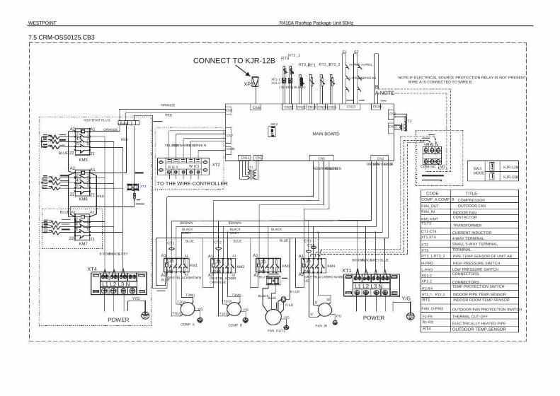
WESTPOINT R410A Rooftop Package Unit 50Hz 7.5 CRM-OSS0125.CB3
S1 RT3_2 RT2_1 RT2_2
S2 H-PRO H-PRO
RT3 _1 RT4 CONNECT TO KJR-12B
XP3
RT1 XP1-2 XS1-2
( WHITE) ( BLACK) NOTE:IF ELECTRICAL SOURCE PROTECTION RELAY IS NOT PRESENT, WIRE A IS CONNECTED TO WIRE B. L-PRO K1 L-PRO K2
B A NOTE
CN40 CN2
ORANGE CN5 CN9 CN20 CN21 CN23 CN24 CN25 CN13
RED 123456 H EATER KIT PL U G T2
SW3 CN12
A2 2 4 6
KM5
1 3 5
A1 ORANGE MAIN BOARD
R S T CN11 CN1
T1 RED
CN7 RED
YELL OW RED WHIT E BLUE GREE N CN36
BLUE 22 21
A1 2 4 6
1 3 5
KM6 21 RED
CN6 BROWN
BROWN YELLOW GREEN CN3
GREYBLACK BLUE A2 R G Y W (C) XT2 COM NC NO SW3
MODE KJR-12B KJR-23B
XT3 TO THE WIRE CONTROLLER CODE
COMP_A,COMP_B FAN_OUT FAN_IN
BROWN BLACK GREY
BROWN BLACK GREY BLACK
22 TITLE COMPRESSOR OUTDOOR FAN
INDOOR FAN CONTACTOR TRANSFORMER CURRENT INDUCTOR 4-WAY TERMINAL SMALL 5-WAY TERMINAL TERMINAL PIPE TEMP.SENSOR OF UNIT AB HIGH PRESSURE SWITCH LOW PRESSURE SWITCH CONNECTORS CONNECTORS TEMP PROTECTION SWITCH
BLUE A2 A1 2 4 6
22 KM7
1 3 5
CT1
KM1-KM7 T1,T2 CT1-CT4 XT1,XT4 XT2 XT3 RT3_1,RT3_2
BROWN BLACK GREY BLUE A1 CT2 BLUE BLUE
A1 A1 135 A1
135 135 41
135 41
CT3 CT4 21
B ROWN B LACK G REY BLUE
XT4 BLUE
KM1 246 KM2 KM3 KM4 H-PRO
L-PRO XS1-2 XP1-2 K1-K4
A2 A2 A2 A2 42 XT1 246 246 42
L1 L2 L3 N Y/G
246 GR EYBLA CKBRO WNBL UE BLU E GREYBL ACKBROWN GR EYBL ACKBR
OWNBLUE L1 L2 L3 N
W B LUE
T3(W) T2(V)
Y/G T1(U) T1(U)
T3(W) T2(V)
Y/G U
V Y/G
Y/G
RT2_1、RT2_2 INDOOR PIPE TEMP.SENSOR RT1 INDOOR ROOM TEMP.SENSOR FAN_O-PRO OUTDOOR FAN PROTECTION SWITCH
THERMAL CUT-OFF ELECTRICALLY HEATED PIPE
F1-F9 R1-R9
BLACK BLUE
POWER Y/G COMP_A COMP_B
FAN_OUT1
R ED POWER
FAN_IN RT4 OUTDOOR TEMP.SENSOR

7.6 CRM-OSS0150.CB3
S1 RT3_2 RT2_1 RT2_2 H-PRO
S2 H-PRO
RT3_1 RT4
TO BE CONNECTED KJR-12B XP1-2 XS1-2
RT1 L -PRO K1 R ED L -PRO K2
XS3
CN5 CN9
(WHITE) (BLACK) JP1 CN22 SW3
NOTE:IF ELECTRICAL SOURCE PROTECTION RELAY IS NOT PRESENT, WIRE A IS CONNECTED TO WIRE B.
CN40 BLUE
CN20 CN21 CN23 CN24 CN25 CN13 A2
2 4 6
22 KM6
BLUE
A B NOTE
F AN_O-PR O1 1 3 5
A1 RED
CN 7 21 WHITE YEL LOW RED BLU E GRE EN WHITE
MAIN BOARD RED RED RED WHITE BLUE R S T
KJR-12B KJR-23B
C N36 ELE ICA S CE CTR L OURPRO TIO R LY TEC N EA A2
2 4 6
22 KM7
BLUE
1 3 5
A1 RED R G Y W (C ) CN11 CN1
T1 CN12 CN2
BROWNRED CN6
BLACKBROWN GREENYELLOW
CN3 GREY BLUE XT2
21 K3
RED
COM NC NO SW3 MODE
TO THE WIRE CONTROLLER T2 CODE FAN_OUT1,2 FAN_IN KM1~KM8 T1,T2 CT1-CT4 XT1,XT4 XT2 RT3_1,RT3_2 RT4 H-PRO L-PRO XS1-3 XP1-2 K1-K3
TITLE OUTDOOR FAN INDOOR FAN CONTACTOR TRANSFORMER CURRENT INDUCTOR 4-WAY TERMINAL SMALL 5-WAY TERMINAL PIPE TEMP.SENSOR OF UNIT AB OUTDOOR TEMP.SENSOR HIGH PRESSURE SWITCH LOW PRESSURE SWITCH CONNECTORS CONNECTORS TEMP PROTECTION SWITCH INDOOR ROOM TEMP.SENSOR INDOOR PIPE TEMP.SENSOR OUTDOOR FAN PROTECTION SWITCH THERMAL CUT-OFF ELECTRICALLY HEATED PIPE
COMP_A,COMP_B COMPRESSOR
A2 2 4 6
22 KM8
A1 1 3 5
21
WHITE XT3 BROWN
BLACK GREY
WHITE BLUE
BROWN BLACK GREY BLUE
BROWN BLACK GREY BLUE
BROWN BLACK GREY BLUE BRO WN BLACK GR EY BLUE
A1 41 A1 41 A1 XT4 135 135 A1
KM3 KM1 135 KM2 135
KM4
CT3 CT4 CT1 CT2
246 246 246 A2 42 A2 246
A2 42 L1 L2 L3 N
Y/G
A2
BROW N
POWER
BLACK G REY BLUE
RT1 XT1
W Y/G
L1 L2 L3 N Y/G
RT2_1,RT2_2RT2
FAN_O-PRO1,2
F1-F9 R1-R9
G REYB LAC KB ROW N GREYB LAC KB ROW NBLUE BLUE GREYBLACKBROWN GREYBLACKBROWNBLUE
T2(V) T3(W) Y/G
T2(V) T3(W) Y/G
V U
W V
U Y/G T1(U)
COMP_A T1(U)
COMP_B FAN_OUT1 FAN_IN POWER

WESTPOINT R410A Rooftop Package Unit 50Hz 7.7 CRM-OSS0175.CB3
S1 RT3_2 RT2_1 RT2_2 H-PRO
S2 H-PRO
RT3_1 RT4
TO BE CONNECTED KJR-12B XP1-2 XS1-2
RT1 L -PRO K1 R ED L -PRO K2
XS3
CN5 CN9
NOTE:IF ELECTRICAL SOURCE PROTECTION RELAY IS NOT PRESENT, WIRE A IS CONNECTED TO WIRE B. (WHITE) (BLACK)
JP1 CN22 SW3
BLUE CN20 CN21 CN23 CN24 CN25 CN13
CN40 A2
2 4 6
22 KM6
BLUE
A B NOTE A1
1 3 5
21
RED WHITE
MAIN BOARD RED RED RED CN 7 WHITE BLUE R S T
CN3
YEL LOW RED BLU E GRE EN WHITE C N36
A2 2 4 6
22 KM7
1 3 5
A1 RED R G Y W (C ) XT2 CN11 T1
CN1 CN12 CN2 BROWNRED
CN6 BLACKBROWN
YELLOW GREEN COM NC NO ELECTRICAL SOURCE PROTECTION RELAY
SW3 MODE KJR-12B
KJR-23B GREY BLUE
TO THE WIRE CONTROLLER 21
K3 RED
T2 CODE TITLE
BLUE A2
2 4 6
22 KM8
1 3 5
A1 WHITE XT3 BROWN
BROWN BLACK GREY
WHITE
BROWN BLACK GREY BLUE
BLACK GREY BLUE
BROWN BLACK GREY BLUE
BROWN BLACK GREY BLUE 21 BLUE
COMP_A,COMP_B COMPRESSOR FAN_OUT1,2 OUTDOOR FAN FAN_IN INDOOR FAN KM1~KM8 CONTACTOR T1,T2 TRANSFORMER CT1-CT4 CURRENT INDUCTOR XT1,XT4 4-WAY TERMINAL XT2 SMALL 5-WAY TERMINAL XT3 2-WAY TERMINAL RT3_1,RT3_2 RT4 H-PRO L-PRO XS1-3 XP1-2 K1-K3 RT1
PIPE TEMP.SENSOR OF UNIT AB OUTDOOR TEMP.SENSOR HIGH PRESSURE SWITCH LOW PRESSURE SWITCH CONNECTORS CONNECTORS TEMP PROTECTION SWITCH INDOOR ROOM TEMP.SENSOR INDOOR PIPE TEMP.SENSOR OUTDOOR FAN PROTECTION SWITCH THERMAL CUT-OFF ELECTRICALLY HEATED PIPE
BROWN BLACK GREY BLUE
A1 A1 21 A1 21 21
A1 CT3 CT4 CT1 CT2
XT4 135 22 KM1 KM3 135
A2 KM2 246 135 KM5
246 246 246 A2 22 A2 22 A2 L1 L2 L3 N
Y/G
22
21 135 BLUE
RED
POWER
BLACK W HIT E BLUE
BLUE XT1 B LUEW HIT ER ED BLUEWHITERED GREYBLACKBROWNBLUE
XT3 BLAC K L1L2 L3 N
POWER
BL UE BLUE
Y/G T2(V) T3(W)
Y/G T2(V) T3(W)
Y/G BLUE
U V
W Y/G T1(U)
COMP_A T1(U)
COMP_B FAN_OUT1 Y/G
FAN_OUT2 Y/G
RT2_1,RT2_2RT2
FAN_O-PRO1,2 F1-F9 R1-R9
B LUE BLUE BLAC K R ED RED
FAN_IN

7.8 CRM-OSS0200.CB3
S1 RT3_2 RT2_1 RT2_2 H-PRO
S2 H-PRO
RT3_1 RT4
TO BE CONNECTED KJR-12B XP1-2 XS1-2
RT1 L -PRO K1 R ED L -PRO K2
XS3
CN5 CN9
NOTE:IF ELECTRICAL SOURCE PROTECTION RELAY IS NOT PRESENT, WIRE A IS CONNECTED TO WIRE B. (WHITE) (BLACK)
JP1 CN22 SW3
BLUE CN20 CN21 CN23 CN24 CN25 CN13
CN40 A2
2 4 6
22 KM6
BLUE
A B NOTE
FAN_O- PRO2 F AN_O-PR O1 A1 1 3 5
RED
21 WHITE YEL LOW RED BLU E GRE EN WHITE
MAIN BOARD RED RED RED CN 7 C N36 WHITE
BLUE R S T CN3 A2
2 4 6
22 KM7
1 3 5
A1 RED R G Y W (C ) Xt2 CN11 T1
CN1 CN12 CN2 BROWNRED
CN6 BLACKBROWN
GREENWHITEYELLOW COM NC NO ELECTRICAL SOURCE PROTECTION RELAY
SW3 MODE KJR-12B
KJR-23B GREY BLUE
TO THE WIRE CONTROLLER 21
K3 RED
T2 CODE
COMP_A,COMP_B
FAN_OUT1,2 FAN_IN KM1~KM8 T1,T2 CT1-CT4 XT1,XT4 XT2 XT3 RT3_1,RT3_2 RT4 H-PRO L-PRO XS1-3 XP1-2 K1-K3 RT1
TITLE COMPRESSOR OUTDOOR FAN INDOOR FAN CONTACTOR TRANSFORMER CURRENT INDUCTOR 4-WAY TERMINAL SMALL 5-WAY TERMINAL MIDDLE TERMINAL PIPE TEMP.SENSOR OF UNIT AB OUTDOOR TEMP.SENSOR HIGH PRESSURE SWITCH LOW PRESSURE SWITCH CONNECTORS CONNECTORS TEMP PROTECTION SWITCH INDOOR ROOM TEMP.SENSOR INDOOR PIPE TEMP.SENSOR OUTDOOR FAN PROTECTION SWITCH
THERMAL CUT-OFF ELECTRICALLY HEATED PIPE
BLUE A2
2 4 6
22 KM8
1 3 5
A1 WHITE XT3 BROWN
BLACK GREY
BROWN BLACK GREY BLUE
BROWN BLACK GREY BLUE
BROWN BLACK GREY BLUE
BROWN BLACK GREY BLUE 21 WHITE BLUE BROWN BLACK GREY BLUE
A1 21 A1 21 A1 21 A1 21 A1 CT3 CT4 CT1 CT2
XT4 135 135 135 KM1 135
KM2 KM3 KM4 135 KM5
246 246 246 246 246 A2 22 22 22 A2 22 A2 A2 A2 L1 L2 L3 N
Y/G
22
21 RED
POWER
BLACK W HIT E BLUE
XT1 B LUEW HIT ER ED BLAC KGREYB ROW N BLACKGREYB ROW N BLUEWHITERED GREYBLACKBROWN L1L2 L3 N
POWER
BLU E BLU E BLU E
T2(V) T3(W) Y/G
BL UE Y/G
T2(V) T3(W) Y/G
V U
W U
V W V
U Y/G
W Y/G T1(U)
COMP_A T1(U)
COMP_B Y/G
FAN_OUT1
RT2_1,RT2_2RT2
FAN_O-PRO1,2
F1-F9 R1-R9
FAN_OUT2 FAN_IN
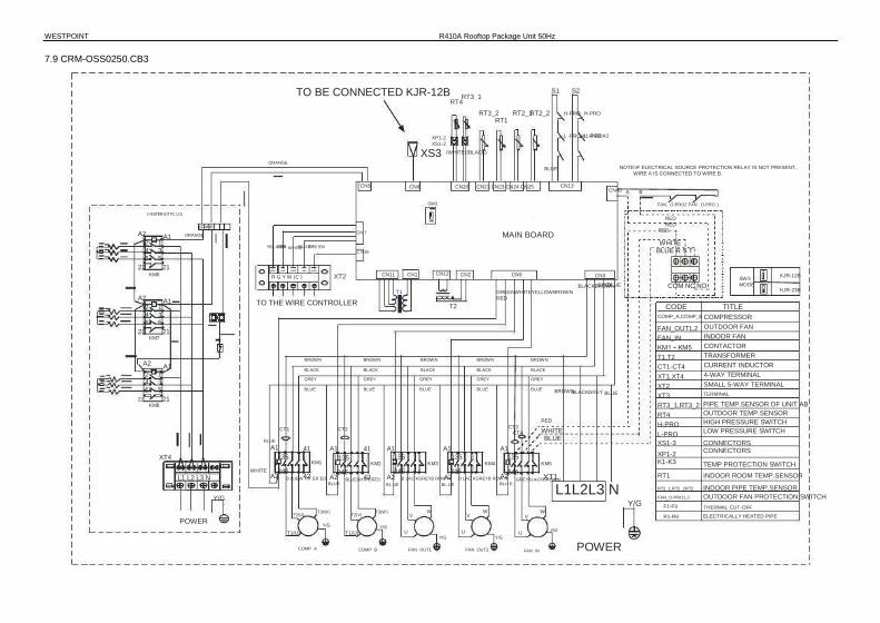
WESTPOINT R410A Rooftop Package Unit 50Hz 7.9 CRM-OSS0250.CB3
TO BE CONNECTED KJR-12B RT4
XP1-2 XS1-2
S1 RT3_2 RT2_1 RT2_2 H-PRO
S2 H-PRO
RT3_1 RT1
L -PRO K1 R ED L -PRO K2 XS3
ORANGE (WHITE) (BLACK)
NOTE:IF ELECTRICAL SOURCE PROTECTION RELAY IS NOT PRESENT, WIRE A IS CONNECTED TO WIRE B.
CN40 BLUE
CN5 CN9 SW3
CN20 CN21 CN23 CN24 CN25 CN13 A B
FAN_ O-PRO2 FAN _O-PRO 1 H EATER KIT PL U G
A2 2 4 6
22 KM6
1 3 5
A1 ORANGE YEL LOW RED BLU E GRE EN WHITE
MAIN BOARD RED RED RED 123456
CN 7 C N36 WHITE
BLUE R S T CN3 KJR-12B
KJR-23B 21
R G Y W (C ) XT2 CN11 T1
CN1 CN12 CN2 CN6 BLACKBROWN
GREENWHITEYELLOWBROWNRED
COM NC NO SW3 MODE GREY BLUE
A2 2 4 6
22 KM7
1 3 5
A1 TO THE WIRE CONTROLLER T2 CODE COMP_A,COMP_B TITLE
COMPRESSOR OUTDOOR FAN INDOOR FAN CONTACTOR TRANSFORMER CURRENT INDUCTOR 4-WAY TERMINAL SMALL 5-WAY TERMINAL TERMINAL
21
A2 2 4 6
22 KM8
BROWN BROWN BLACK GREY BLUE
BROWN BLACK GREY BLUE
BROWN BLACK GREY BLUE
BROWN BLACK GREY BLUE
A1 1 3 5
21
BLACK GREY BLUE
RED CT3 CT4 CT1 CT2 WHITE
BLUE KM5
FAN_OUT1,2 FAN_IN KM1~KM5 T1,T2 CT1-CT4 XT1,XT4 XT2 XT3 RT3_1,RT3_2 RT4 H-PRO L-PRO XS1-3 XP1-2 K1-K3 RT1 RT2_1,RT2_2RT2
FAN_O-PRO1,2
F1-F9 R1-R9
BROWN BLACK GREY BLUE PIPE TEMP.SENSOR OF UNIT AB OUTDOOR TEMP.SENSOR HIGH PRESSURE SWITCH LOW PRESSURE SWITCH CONNECTORS CONNECTORS TEMP PROTECTION SWITCH INDOOR ROOM TEMP.SENSOR INDOOR PIPE TEMP.SENSOR OUTDOOR FAN PROTECTION SWITCH THERMAL CUT-OFF ELECTRICALLY HEATED PIPE
A1 41 A1 41 A1 A1 135 135 135 A1
KM4 XT4 WHITE KM1 135
KM2 KM3 246 246 246 246 246
135 A2 42 A2 42 A2 L1 L2 L3 N
Y/G A2 A2
BLUE
XT1 B LUEW HIT ER ED B LAC KGREYB ROW N B LAC KGREYB ROW N BLUEWHITERED GREYBLACKBROWN L1L2L3 N
POWER
POWER T2(V) T3(W) Y/G
BLUE BLU E
T2(V) T3(W) Y/G
BL UE BL UE Y/G
V U
W U
V W U
V Y/G
W Y/G T1(U)
COMP_A T1(U)
COMP_B Y/G
FAN_OUT1 FAN_OUT2 FAN_IN

7.10 CRM-OSS0300.CB3
TO BE CONNECTED KJR-12B RT4
XP1-2 XS1-2
S1 RT3_2 RT2_1 RT2_2 H-PRO
S2 H-PRO
RT3_1 RT1
L -PRO K1 R ED L -PRO K2 XS3
ORANGE (WHITE) (BLACK)
NOTE:IF ELECTRICAL SOURCE PROTECTION RELAY IS NOT PRESENT, WIRE A IS CONNECTED TO WIRE B.
CN40 BLUE
CN5 CN9 SW3
CN20 CN21 CN23 CN24 CN25 CN13 A B
FAN_ O-PRO2 FAN _O-PRO 1 H EATER KIT PL U G
A2 2 4 6
22 KM6
1 3 5
A1 ORANGE YEL LOW RED BLU E GRE EN WHITE
MAIN BOARD RED RED RED 123456
CN 7 C N36 WHITE
BLUE R S T CN3 KJR-12B
KJR-23B 21
R G Y W (C ) XT2 CN11 T1
CN1 CN12 CN2 CN6 BLACKBROWN
GREENWHITEYELLOWBROWNRED
COM NC NO SW3 MODE GREY BLUE
A2 2 4 6
22 KM7
1 3 5
A1 TO THE WIRE CONTROLLER T2 CODE COMP_A,COMP_B TITLE
COMPRESSOR OUTDOOR FAN INDOOR FAN CONTACTOR TRANSFORMER CURRENT INDUCTOR 4-WAY TERMINAL SMALL 5-WAY TERMINAL TERMINAL
21
A2 2 4 6
22 KM8
BROWN BROWN BLACK GREY BLUE
BROWN BLACK GREY BLUE
BROWN BLACK GREY BLUE
BROWN BLACK GREY BLUE
A1 1 3 5
21
BLACK GREY BLUE
RED CT3 CT4 CT1 CT2 WHITE
BLUE KM5
FAN_OUT1,2 FAN_IN KM1~KM5 T1,T2 CT1-CT4 XT1,XT4 XT2 XT3 RT3_1,RT3_2 RT4 H-PRO L-PRO XS1-3 XP1-2 K1-K3 RT1 RT2_1,RT2_2RT2
FAN_O-PRO1,2
F1-F9 R1-R9
BROWN BLACK GREY BLUE PIPE TEMP.SENSOR OF UNIT AB OUTDOOR TEMP.SENSOR HIGH PRESSURE SWITCH LOW PRESSURE SWITCH CONNECTORS CONNECTORS TEMP PROTECTION SWITCH INDOOR ROOM TEMP.SENSOR INDOOR PIPE TEMP.SENSOR OUTDOOR FAN PROTECTION SWITCH THERMAL CUT-OFF ELECTRICALLY HEATED PIPE
A1 41 A1 41 A1 A1 135 135 135 A1
KM4 XT4 WHITE KM1 135
KM2 KM3 246 246 246 246 246
135 A2 42 A2 42 A2 L1 L2 L3 N
Y/G A2 A2
BLUE
XT1 B LUEW HIT ER ED B LAC KGREYB ROW N B LAC KGREYB ROW N BLUEWHITERED GREYBLACKBROWN L1L2L3 N
POWER
POWER T2(V) T3(W) Y/G
BLUE BLU E
T2(V) T3(W) Y/G
BL UE BL UE Y/G
V U
W U
V W U
V Y/G
W Y/G T1(U)
COMP_A T1(U)
COMP_B Y/G
FAN_OUT1 FAN_OUT2 FAN_IN

WESTPOINT R410A Rooftop Package Unit 50Hz T1 application 7.11 CRM-OSS062.HB3
TO THE WIRE CONTROLLER XT4 HEAT PUMPONLY
4-WAY VALVE
GREEN BRO WN YELLOW BLU E
RED
CN4 T6
CN2 MAIN CONTROL BOARD
CT CN3
T5 BLUE PURPLE
CN7 CN8
WIRING DIAGRAM CODE COMP FAN1 FAN2 CAP1 CAP2 XP1-5 XS1-5 RT1-4 KM1 T5 T6 K1 K2
PART NAME COMPRESSOR INDOOR FAN OUTDOOR FAN INDOOR FAN CAP OUTDOOR FAN CAP CONNECTORS CONNECTORS TEMP.SENSOR AC CONTACTOR TRANSFORMER(24V~) TRANSFORMER HIGH PRESS SWITCH COMP.TEMP. SWITH LOW PRESS SWITCH 4-WAY TERMINAL MIDDLE TERMINAL 6-WAY TERMINAL
CN13 CN32 CN34 RY RL4 CN36 CN37 CN15 CN30
XP5 XS5
CN6 RT3 RT4
XS2 XP2 XS1XP1 BLACK RED COM NO
BLACK BLUE
24V
BLACKBLACK WHITE BLUE FAN1
Y/G BROWN XT2 BLUE
Y/G FAN2
WHITE
BROWN L-PRO BROWN
CN49
K1
CN1 B Y G C R BLUE CN33
BLUE CN48
BROWN
RT2 K2 RT1
RED RED XP3 XS3
BLACK CAP1 BROWN
H EAT HEAT PUMP ONLY
XT1 CAP2 RED
L1 L2 L3 N Y/G
WHITE BLUE
BLACK
A1 1 3 5 21
KM1 A2 2 4 6 22
U W RED COMP Y/G
V WHITE
BLUE L-PRO XT1 XT2 XT4 POWER
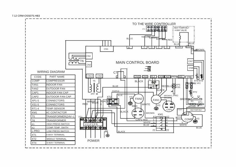
7.12 CRM-OSS075.HB3
TO THE WIRE CONTROLLER XT4 HEAT PUMPONLY
4-WAY VALVE YELLOW GREEN BLU E BRO WN RED
CN4 T6
CN2 MAIN CONTROL BOARD
CT CN3
T5 BLUE PURPLE
CN7 CN8
WIRING DIAGRAM CODE COMP FAN1 FAN2 CAP1 CAP2 XP1-5 XS1-5 RT1-4 KM1 T5 T6 K1 K2
PART NAME COMPRESSOR INDOOR FAN OUTDOOR FAN INDOOR FAN CAP OUTDOOR FAN CAP CONNECTORS CONNECTORS TEMP.SENSOR AC CONTACTOR TRANSFORMER(24V~) TRANSFORMER HIGH PRESS SWITCH COMP.TEMP. SWITH LOW PRESS SWITCH 4-WAY TERMINAL MIDDLE TERMINAL 6-WAY TERMINAL
CN13 CN32 CN34 RY RL4 CN36 CN37 CN15 CN30
XP5 XS5
CN6 RT3 RT4
XS2 XP2 XS1XP1 BLACK RED COM NO
BLACK BLUE
24V
BLACKBLACK
WHITE BLUE FAN1 Y/G
BROWN XT2 BLUE Y/G
FAN2 WHITE
BROWN L-PRO BROWN
CN49
K1
CN1 B Y G C R BLUE CN33
BLUE CN48
BROWN
RT2 K2 RT1
RED RED XP3 XS3
BLACK CAP1 BROWN
H EAT HEAT PUMP ONLY
XT1 CAP2 RED
L1 L2 L3 N Y/G
WHITE BLUE
BLACK
A1 1 3 5 21
KM1 A2 2 4 6 22
U W RED COMP Y/G
V WHITE
BLUE L-PRO XT1 XT2 XT4 POWER

WESTPOINT R410A Rooftop Package Unit 50Hz 7.13 CRM-OSS085.HB3
S1 S2 H-PRO H-PRO
RT3_1 RT4
(BLACK)
TO BE CONNECTED KJR-12B
XP1-2 XS1-2
RT3_2 RT2_1 RT2_2 RT1
L-PRO K 1 RED L-PRO K 2 XS3
CN22 CN9
NOTE:IF ELECTRICAL SOURCE PROTECTION RELAY IS NOT PRESENT, WIRE A IS CONNECTED TO WIRE B. (WHITE)
BLUE CN20
SW3 CN21 CN23 CN24 CN25 CN13
CN29 CN28
BLUE 4-WAY(B) BLUE CN7
4-WAY(A) YE LL OW CN40
WHITE GREEN BLUE RED MAIN BOARD BLUE BLUE A B
NOTE CN36
R G Y B (C) XT2 CN11 T1
CN1 CN12 CN2 CN6 RY5 CN3 BRO WN GREY BLUE BLACK
RED BROWN GREEN BROWN BLACK TO THE WIRE CONTROLLER T2 BLUE
BLUE SW3 MODE KJR-12B
KJR-25B CODE
RED RED
BROWN BLACK GREY BLUE
BROWN B L A C K BLACK GREY BLUE
BLACK BLUE
TITLE COMP_A,COMP_B COMPRESSOR F AN _OU T 1 ,2 OUTDOOR FAN FAN_IN INDOOR FAN KM1-KM4 CONTACTOR T1,T2 CT1-CT4 XT1 XT2 XT3,XT4 RT3_1,RT3_2 RT4 H-PRO L-PRO XS1-3
TRANSFORMER CURRENT INDUCTOR 4-WAY TERMINAL SMALL 5-WAY TERMINAL 2-WAY TERMINAL PIPE TEMP.SENSOR OF UNIT AB OUTDOOR TEMP.SENSOR HIGH PRESSURE SWITCH LOW PRESSURE SWITCH CONNECTORS CONNECTORS TEMP PROTECTION SWITCH INDOOR ROOM TEMP.SENSOR
BLU E
BROWN BLACK GREY BLUE
RED CT3 CT4
KM1 A1 A1 A1 21 21 21 BLACK BLACK KM2 KM3
BLUE
WHITE BLUE R S T
BROWN BLACK GREY BLUE ELECTRICAL SOURCE PROTECTION REALY 135
CT1
135
CT2
135 KM4
246 246 22 A2 22 A2 246 COM NC NO A2 22 BROWN GREYBLACK GR EYBL ACKBROWN BROWN BLACKGREY
BROWN BROWN BL UE BL UE
T2(V) T1(U)
COMP_A
T3(W) Y/G
BL U E XT1
U W Y/G
L1 L2 L3 N XP1-2 K1,K2 RT1
W HITER EDBLUEB LACK T2(V)
T1(U) T3(W)
Y/G Y/G V
FAN_OUT1 RTRT22_1、R T 2_2 INDOOR PIPE TEMP.SENSOR
FAN_IN COMP_B POWER F AN_O-PRO1、2 OUTDOOR FAN PROTECTION SWITCH

7.14 CRM-OSS100.HB3 S1
RT3_2 RT2_1 RT2_2 H-PRO S2
H-PRO RT3_1 RT4
(BLACK)
TO BE CONNECTED KJR-12B
XP1-2 XS1-2
RT1 L-PRO L-PRO
XS3
CN22 CN7
NOTE:IF ELECTRICAL SOURCE PROTECTION RELAY IS NOT PRESENT, WIRE A IS CONNECTED TO WIRE B. (WHITE)
K1 BLUE RED
K2
CN9 SW3
CN20 CN21 CN23 CN24 CN25 CN13 CN29 CN28
BLUE 4-WAY(B)
BLUE 4-WAY(A)
YE LL OW CN40 WHITE GREEN
BLUE RED MAIN BOARD BLUE BLUE A B
NOTE FAN _O-P RO1 CN36
R G Y B (C) XT2 CN11 T1
CN1 CN12 CN2 RED
CN6 BRO WN BLACK
BROWN YELLOW GREEN CN3 GREY BLUE
TO THE WIRE CONTROLLER T2 BLUE BLUE SW3
MODE KJR-12B KJR-25B
CODE RED
RED BROWN BLACK GREY BLUE
BROWN BLACK GREY BLUE
BROWN BLACK GREY BLUE
BROWN BLACK GREY BLUE BLU E
TITLE COMP_A,COMP_B COMPRESSOR F AN _OU T 1、 2 OUTDOOR FAN FAN_IN INDOOR FAN KM1-KM4 CONTACTOR T1,T2 CT1-CT4 XT1 XT2 RT3_1,RT3_2 RT4 H-PRO L-PRO XS1-3
TRANSFORMER CURRENT INDUCTOR 4-WAY TERMINAL SMALL 5-WAY TERMINAL PIPE TEMP.SENSOR OF UNIT AB OUTDOOR TEMP.SENSOR HIGH PRESSURE SWITCH LOW PRESSURE SWITCH CONNECTORS CONNECTORS TEMP PROTECTION SWITCH INDOOR ROOM TEMP.SENSOR
CT3 CT4
RED KM1
A1 A1 A1 21 A1 21 21 21 BLACK BLACK KM2 WHITE BLUE R S T
BROWN BLACK GREY BLUE ELECTRICAL SOURCE PROTECTION REALY 135
CT1
135
CT2
135 KM3 135
KM4 246 246 246 22 A2 22 A2 22 A2 246 COM NC NO
A2 22 BROWN GREYBLACK GR EYBL ACKBROWN GRE YBL ACKBROWN BLACKGREYBROWN BROWN BROWN BL UE BL UE
T2(V) T1(U)
COMP_A
T3(W) Y/G
BL U E
T2(V) T1(U)
COMP_B
T3(W) Y/G
B LUE XT1
V U
FAN_OUT
Y/G L1 L2 L3 N
XP1-2 K1,K2 RT1 W
U V
FAN_IN
W RTRT22_1,R T 2_2 INDOOR PIPE TEMP.SENSOR F AN_O-PRO1、2 OUTDOOR FAN PROTECTION SWITCH
Y/G POWER

WESTPOINT R410A Rooftop Package Unit 50Hz 7.15 CRM-OSS125.HB3
S1 RT3_2 RT2_1 RT2_2 H-PRO
S2 H-PRO
RT3_1RT4
(BLACK)
TO BE CONNECTED KJR-12B
XP1-2 XS1-2
RT1 L-PRO K1 RED L-PRO K2
XS3
CN22 CN9
NOTE:IF ELECTRICAL SOURCE PROTECTION RELAY IS NOT PRESENT, WIRE A IS CONNECTED TO WIRE B. (WHITE)
BLUE CN20 CN21 CN23 CN24 CN25 CN13
CN29 CN28
BL UE 4-WAY (B) BLUE CN7
4-WAY(A) YEL LOW CN40 WHITE GREEN BLUE RED MAIN BOARD BLUE BLUE A B CN36
NOTE FAN _O-PRO1
R G Y B (C) XT2 CN11 T1
CN1 CN12 CN2 RED
CN6 CN3 GREY BLUE BROWN BLACK
GREENYELLOW BROWN TO THE WIRE CONTROLLER T2 BLUE
BLUE SW3 MODE
KJR-12B KJR-25B
CODE RED
RED BROWN BLACK GREY BLUE
BROWN BLACK GREY BLUE
BROWN BLACK GREY BLUE
BROWN BLACK GREY BLUE
TITLE COMP_A,COMP_B COMPRESSOR
CT3 CT4
RED KM1
A1 A1 A1 135 135 41 41
135 A1 BLACK BLACK KM2 WHITE BLUE R S T
KM3 KM4 246 246 246 42 A2 A2 42 A2 A2 246 COM NC NO
XT1 T2(V)
T1(U) COMP_A
Y/G L 1 L2 L 3 N
FAN _OU T1、 2 OUTDOOR FAN FAN_IN INDOOR FAN KM1-KM4 CONTACTOR T1,T2 TRANSFORMER CT1-CT4 CURRENT INDUCTOR XT1 4-WAY TERMINAL XT2 SMALL 5-WAY TERMINAL RT3_1,RT3_ 2 PIPE TEMP.SENSOR OF UNIT AB RT4 OUTDOOR TEMP.SENSOR H-PRO HIGH PRESSURE SWITCH L-PRO LOW PRESSURE SWITCH XS1-3 CONNECTORS XP1-2 CONNECTORS K1,K2 TEMP PROTECTION SWITCH RT1 INDOOR ROOM TEMP.SENSOR R T2_1、 R T2_2 INDOOR PIPE TEMP.SENSORRT2 FAN_O-PRO1、2 OUTDOOR FAN PROTECTION SWITCH
BLUE CT1 CT2
BROWN BLACK GREY BLUE 135
GREYBLACKBROWN BL UE GREYBLACKBROWN GREYBLACKBROWN GREYBLACKBROWN
BLUE
T3(W) Y/G
B LUE
T2(V) T1(U)
COMP_B
T3(W) Y/G
B LUE
V U
FAN_OUT
W V
U Y/G
W
FAN_IN POWER
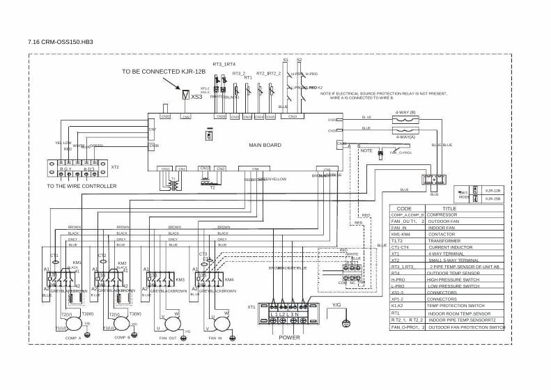
7.16 CRM-OSS150.HB3
S1 RT3_2 RT2_1 RT2_2 H-PRO
S2 H-PRO
RT3_1RT4
(BLACK)
TO BE CONNECTED KJR-12B
XP1-2 XS1-2
RT1 L-PRO K1 RED L-PRO K2
XS3
CN22 CN9
NOTE:IF ELECTRICAL SOURCE PROTECTION RELAY IS NOT PRESENT, WIRE A IS CONNECTED TO WIRE B. (WHITE)
BLUE CN20 CN21 CN23 CN24 CN25 CN13
CN29 CN28
BL UE 4-WAY (B) BLUE CN7
4-WAY(A) YEL LOW CN40 WHITE GREEN BLUE RED MAIN BOARD BLUE BLUE A B CN36
NOTE FAN _O-PRO1
R G Y B (C) XT2 CN11 T1
CN1 CN12 CN2 RED
CN6 CN3 GREY BLUE BROWN BLACK
GREENYELLOW BROWN TO THE WIRE CONTROLLER T2 BLUE
BLUE SW3 MODE
KJR-12B KJR-25B
CODE RED
RED BROWN BLACK GREY BLUE
BROWN BLACK GREY BLUE
BROWN BLACK GREY BLUE
BROWN BLACK GREY BLUE
TITLE COMP_A,COMP_B COMPRESSOR
CT3 CT4
RED KM1
A1 A1 A1 135 135 41 41
135 A1 BLACK BLACK KM2 WHITE BLUE R S T
KM3 KM4 246 246 246 42
A2 A2 42 A2 A2 246 COM NC NO
XT1 T2(V)
T1(U) COMP_A
Y/G L 1 L2 L 3 N
FAN _OU T1、 2 OUTDOOR FAN FAN_IN INDOOR FAN KM1-KM4 CONTACTOR T1,T2 TRANSFORMER CT1-CT4 CURRENT INDUCTOR XT1 4-WAY TERMINAL XT2 SMALL 5-WAY TERMINAL RT3_1,RT3_ 2 PIPE TEMP.SENSOR OF UNIT AB RT4 OUTDOOR TEMP.SENSOR H-PRO HIGH PRESSURE SWITCH L-PRO LOW PRESSURE SWITCH XS1-3 CONNECTORS XP1-2 CONNECTORS K1,K2 TEMP PROTECTION SWITCH RT1 INDOOR ROOM TEMP.SENSOR R T2_1、R T2_2 INDOOR PIPE TEMP.SENSORRT2 FAN_O-PRO1、2 OUTDOOR FAN PROTECTION SWITCH
BLUE CT1 CT2
BROWN BLACK GREY BLUE 135
GREYBLACKBROWN BL UE GREYBLACKBROWN GREYBLACKBROWN GREYBLACKBROWN
BLUE
T3(W) Y/G
B LUE
T2(V) T1(U)
COMP_B
T3(W) Y/G
B LUE
V U
FAN_OUT
W V
U Y/G
W
FAN_IN POWER

WESTPOINT R410A Rooftop Package Unit 50Hz
7.17 CRM-OSS175.HB3
S1 RT3_2 RT2_1 RT2_2 H-PR O
S2 H-PR O
RT3_1 RT4
TO BE CONNECTED KJR-12B
XS3
CN9
XP1-2 XS1-2
RT1 L-PRO L-PRO
(W HITE) (BLACK) JP1 CN22
K1 BL UE
RED K2 NOTE:IF ELECTRICAL SOURCE PROTECTION RELAY IS NOT PRESENT,
WIRE A IS CONNECTED TO WIRE B. CN20
SW3 CN21 CN23 CN24 CN25 CN13 4-WAY(B)
CN29 CN28
B LUE B LUE CN7
4-WAY(A) Y EL LO W CN40
WHITE GREEN BLUE RED MAIN BOARD BLUE BLUE A B
NOTE CN36
R G Y B (C) XT2 CN11 T1
CN1 CN12 CN2 RED
CN6 BROWN BLACK
B ROWN YELLOW GREEN CN3 GREY BLUE
XT4 TO THE WIRE CONTROLLER T2
BLUE BLUE
SW3 MODE KJR-12B
KJR-25B CODE
RED RED
BROWN BLACK GREY BLUE
BROWN BLACK GREY BLUE
BLACK BROWN BLACK GREY BLUE
RED BROWN
BL UE
TITLE COMP_A,COMP_B COMPRESSOR F AN _OU T 1、2 OUTDOOR FAN FAN_IN INDOOR FAN KM1-KM5 T1,T2 CT1-CT4
CONTACTOR TRANSFORMER CURRENT INDUCTOR 4-WAY TERMINAL SMALL 5-WAY TERMINAL 2-WAY TERMINAL PIPE TEMP.SENSOR OF UNIT AB OUTDOOR TEMP.SENSOR HIGH PRESSURE SWITCH LOW PRESSURE SWITCH CONNECTORS CONNECTORS TEMP PROTECTION SWITCH INDOOR ROOM TEMP.SENSOR
KM1 KM2 WHITE BLUE R S T
BROW N BLACK GREY BLUE CT3 CT4 CT1 CT2
XT1 XT2 XT3、 XT4 RT3_1,RT3_2 RT4 H-PRO L-PRO XS1-3
A1 A1 A1 A1 21 135 21 21
135 135 135 KM3 KM5
21 BROWN
246 246 246 22 A2 A2 22
A2 22 A2 246 COM NC NO
22 B LUEWHI TERED B KLAC BLACKGRE YB ROWN BLUEWHITERED BR OWN BR OWN B LU E
T2(V) T1(U)
COMP_A
T3(W) Y/G
BL UE BLU E
T2(V) T1(U)
COMP_B
T3(W) Y/G
B LU E XT3
B LUE XT1
W L1L2L3 N
Y/G
XP1-2 K1,K2
BLA CK BLUE
RED U V
FAN_IN
Y/G
FAN_OUT1
BLUE BL UE RT1 BL ACK
Y/G Y/G RED
RTRT22_1、RT2_2 INDOOR PIPE TEMP.SENSOR F AN_O-PRO1、2 OUTDOOR FAN PROTECTION SWITCH Jp1 NET JUMPER
FAN_OUT2 POWER

7.18 CRM-OSS200.HB3
S1 RT3_2 RT2_1 RT2_2 H-PR O
S2 H-PR O
RT3_1 RT4
TO BE CONNECTED KJR-12B
XS3
CN9
XP1-2 XS1-2
RT1 L-PRO L-PRO
(W HITE) (BLACK) JP1 CN22
K1 BL UE
RED K2 NOTE:IF ELECTRICAL SOURCE PROTECTION RELAY IS NOT PRESENT,
WIRE A IS CONNECTED TO WIRE B. CN20
SW3 CN21 CN23 CN24 CN25 CN13 4-WAY(B)
CN29 CN28
B LUE B LUE CN7
4-WAY(A) Y EL LO W CN40
WHITE GREEN BLUE RED MAIN BOARD BLUE BLUE A B
NOTE FAN _ O-P RO2 FAN_O- PRO1
CN36
R G Y B (C) XT2 CN11 T1
CN1 CN12 CN2 RED
CN6 BROWN BLACK
B ROWN YELLOW GREENWHITE CN3 GREY BLUE
TO THE WIRE CONTROLLER T2 BLUE
BLUE SW3 MODE KJR-12B
KJR-25B CODE
RED RED
BROWN BLACK GREY BLUE
BROWN BLACK GREY BLUE
BROWN BLACK GREY BLUE
BROWN BLACK GREY BLUE
BROWN BLACK GREY BLUE
RED BROWN
BL UE
TITLE COMP_A,COMP_B COMPRESSOR F AN _OU T 1、 2 OUTDOOR FAN FAN_IN KM1-KM5 T1,T2 CT1-CT4 XT1 XT2 RT3_1,RT3_2 RT4 H-PRO L-PRO XS1-3
INDOOR FAN CONTACTOR TRANSFORMER CURRENT INDUCTOR 4-WAY TERMINAL SMALL 5-WAY TERMINAL PIPE TEMP.SENSOR OF UNIT AB OUTDOOR TEMP.SENSOR HIGH PRESSURE SWITCH LOW PRESSURE SWITCH CONNECTORS CONNECTORS TEMP PROTECTION SWITCH INDOOR ROOM TEMP.SENSOR
KM1 KM2 WHITE BLUE R S T
BROW N BLACK GREY BLUE A1 A1 A1 A1 A1 21 21 135 21 21
135 135 135 135 KM4 KM5 KM3
21 BROWN CT3 CT4 CT1 CT2
246 246 246 246 22 A2 22 22 A2 A2 A2 22 A2 246 COM NC NO 22 B LUEWHI TERED G REYBLACKBR OWN GREYB LACKB ROWN BLACKGREYB ROWN BLUEWHITERED
BR OWN BR OWN BL UE B LU E
T2(V) T1(U)
COMP_A
T3(W) Y/G
BL UE BLU E
T2(V) T1(U)
COMP_B
T3(W) Y/G
B LU E XT1
W V
U W
U V W
L1L2L3 N
Y/G
XP1-2 K1,K2
U V
FAN_IN
Y/G RT1 RTRT22_1、RT2_2 INDOOR PIPE TEMP.SENSOR F AN_O-PRO1、2 OUTDOOR FAN PROTECTION SWITCH Jp1 NET JUMPER Y/G
FAN_OUT1 Y/G
FAN_OUT2 POWER

WESTPOINT R410A Rooftop Package Unit 50Hz
9. Electrical Data
Tropical Application Power Supply
Model MCA
CRM-OSS062.CB3 CRM-OSS075.CB3 CRM-OSS085.CB3 CRM-OSS0100.CB3 CRM-OSS0125.CB3 CRM-OSS0150.CB3 CRM-OSS0175.CB3 CRM-OSS0200.CB3 CRM-OSS0250.CB3 CRM-OSS0300.CB3
23.5 29.4 29.6 30.2 41.5 45.4 57.4 64.1 74.7 84.3
TOCA
28.9 36.5 36.3 37.3 52.9 58.1 68.1 77.9 93.4
104.6
MFA
33.2 43.7 47.2 49.4 66.4 72.4 90.6
101.5 116.0 133.4
STC
75 121.2
62 66
64+139 64+144
139 144 158 197
RNC
9.7 14.3 8.8 9.6
8.3+16.6 8.3+18.7
16.6 18.7
20.66 24.52
IPT
5.65 8.08 5.13 5.7
4.75+9.16 4.75+10.8
9.16 10.8 12.1 13.7
Qty
1 1 2 2
1+1 1+1
2 2 2 2
RNC
7.22 7.18 2.90 3.50 4.84 7.50 6.60 8.90 9.70 13.6
IPT
1.62 1.61 1.39 1.84 2.03 3.97 3.03 4.35 4.4 7.4
Qty
1 1 1 1 1 1 1 1 1 1
Compressor Evaporator fan motor Condenser fan motor RNC (each)
3.65 3.93 3.93 2.51 3.66 2.80 3.53 2.84 3.71 3.71
IPT (each)
0.83 0.88 0.88 0.98 0.83 1.27 0.80 1.29 2.07 2.07
Qty
1 1 1 1 1 1 2 2 2 2
Voltage imbalance between phases to be <2% MCA: Min. Current Amps. (A) MFA: Max. Fuse Amps. (A) RNC: Running Current (A)
TOCA: Total Over-current Amps. (A) STC: Starting Current (A) IPT: Input (kW)
T1 Application Power Supply
Model MCA
CRM-OSS062.HB3 CRM-OSS075.HB3 CRM-OSS085.HB3 CRM-OSS100.HB3 CRM-OSS125.HB3 CRM-OSS150.HB3 CRM-OSS175.HB3 CRM-OSS200.HB3
23.5 29.4 29.6 30.2 41.5 45.4 57.4 64.1
TOCA
28.9 36.5 36.3 37.3 52.9 58.1 68.1 77.9
MFA
33.2 43.7 47.2 49.4 66.4 72.4 90.6
101.5
STC
75 121.2
62 66
64+139 64+144
139 144
RNC
9.7 14.3 8.8 9.6
8.3+16.6 8.3+18.7
16.6 18.7
IPT
5.65 8.08 5.13 5.7
4.75+9.16 4.75+10.8
9.16 10.8
Qty
1 1 2 2
1+1 1+1
2 2
RNC
7.22 7.18 2.90 3.50 4.84 7.50 6.60 8.90
IPT
1.62 1.61 1.39 1.84 2.03 3.97 3.03 4.35
Qty
1 1 1 1 1 1 1 1
Compressor Evaporator fan motor Condenser fan motor RNC (each)
3.65 3.93 3.93 2.51 3.66 2.80 3.53 2.84
IPT (each)
0.83 0.88 0.88 0.98 0.83 1.27 0.80 1.29
Qty
1 1 1 1 1 1 2 2
Voltage imbalance between phases to be <2% MCA: Min. Current Amps. (A) MFA: Max. Fuse Amps. (A) RNC: Running Current (A)
TOCA: Total Over-current Amps. (A) STC: Starting Current (A) IPT: Input (kW)
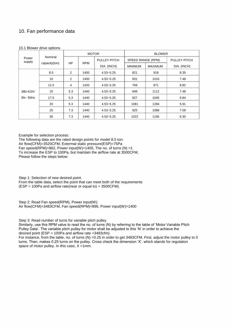
10. Fan performance data
10.1 Blower drive options
Power supply
Nominal capacity(ton)
8.5 10
12.5 380-415V 3N~ 50Hz
15 17.5 20 25 30
HP
2 2 4
5.3 5.3 5.3 7.3 7.3
MOTOR
RPM
1400 1400 1420 1440 1440 1440 1440 1440
PULLEY PITCH DIA. (INCH) 4.53~5.25 4.53~5.25 4.53~5.25 4.53~5.25 4.53~5.25 4.53~5.25 4.53~5.25 4.53~5.25
BLOWER SPEED RANGE (RPM) MINIMUM
821 931 769 949 927
1081 925
1022
MAXIMUM 918
1016 871
1112 1045 1284 1088 1195
PULLEY PITCH DIA. (INCH)
8.35 7.48 8.82 7.48 9.84 5.91 7.09 6.30
Example for selection process: The following data are the rated design points for model 8.5 ton: Air flow(CFM)=3520CFM, Extermal static pressure(ESP)=75Pa Fan speed(RPM)=862, Power input(W)=1405, The no. of turns (N) =1 To increase the ESP to 100Pa, but maintain the airflow rate at 3500CFM, Please follow the steps below:
Step 1: Selection of new desired point. From the table data, select the point that can meet both of the requirements (ESP = 100Pa and airflow rate(near or equal to) = 3500CFM).
Step 2: Read Fan speed(RPM), Power input(W): Air flow(CFM)=3483CFM, Fan speed(RPM)=896, Power input(W)=1400
Step 3: Read number of turns for variable pitch pulley. Similarly, use this RPM valve to read the no. of turns (N) by referring to the table of ‘Motor Variable Pitch Pulley Data’. The variable pitch pulley for motor shall be adjusted to this ‘N’ in order to achieve the desired point (ESP = 100Pa and airflow rate =3483cfm). For instance, from the table, no. of turns (N) =0.25 in order to get 3483CFM. First, adjust the motor pulley to 0 turns. Then, makes 0.25 turns on the pulley. Cross check the dimension ‘X’, which stands for regulation space of motor pulley. In this case, X =1mm.

WESTPOINT R410A Rooftop Package Unit 50Hz
10.2 Model: 6.2Ton
Static pressure(Pa)
Fan speed(RPM) 0 Power input(W)
Air flow(CFM) Fan speed(RPM)
50 Power input(W) Air flow(CFM) Fan speed(RPM)
80 Power input(W) Air flow(CFM) Fan speed(RPM)
100 Power input(W) Air flow(CFM) Fan speed(RPM)
150 Power input(W) Air flow(CFM) Fan speed(RPM)
200 Power input(W) Air flow(CFM) Fan speed(RPM)
250 Power input(W) Air flow(CFM)
High speed
1001 1665 3001 1063 1607 2909 1098 1582 2825 1122 1526 2759 1173 1452 2560 1219 1375 2367 1265 1305 2182
Middle speed
901 1386 2647 972
1341 2564 1016 1317 2503 1047 1280 2401 1106 1230 2250 1162 1182 2109
/ / /
Low speed
810 1164 2356 899
1133 2270 946
1120 2190 977
1079 2105
/ / / / / / / / /

10.3 Model: 7.5Ton
Static pressure(Pa)
Fan speed(RPM) 0 Power input(W)
Air flow(CFM) Fan speed(RPM)
50 Power input(W) Air flow(CFM) Fan speed(RPM)
80 Power input(W) Air flow(CFM) Fan speed(RPM)
100 Power input(W) Air flow(CFM) Fan speed(RPM)
150 Power input(W) Air flow(CFM) Fan speed(RPM)
200 Power input(W) Air flow(CFM) Fan speed(RPM)
250 Power input(W) Air flow(CFM)
High speed
1035 1716 3074 1081 1652 2981 1110 1650 2951 1127 1591 2825 1173 1525 2657 1217 1449 2483 1263 1420 2331
Middle speed
936 1432 2697 991
1409 2596 1026 1360 2574 1051 1377 2438 1110 1338 2313 1165 1281 2187
/ / /
Low speed
844 1197 2403 909
1160 2284 954
1137 2223 984
1126 2146
/ / / / / / / / /

WESTPOINT R410A Rooftop Package Unit 50Hz
10.4 Model: 8.5Ton
ESP(Pa) N X
Fan speed(RPM) 0 Power input(W)
Air flow(CFM) Fan speed(RPM)
25 Power input(W) Air flow(CFM)
Fan speed(RPM) 50 Power input(W)
Air flow(CFM) Fan speed(RPM)
75 Power input(W) Air flow(CFM)
Fan speed(RPM) 100 Power input(W)
Air flow(CFM) Fan speed(RPM)
125 Power input(W) Air flow(CFM)
Fan speed(RPM) 150 Power input(W)
Air flow(CFM) Fan speed(RPM)
175 Power input(W) Air flow(CFM)
Fan speed(RPM) 200 Power input(W)
Air flow(CFM) Notes: 1. 2. 3. 4.
Legend: X: Regulation Space of Motor Pulley (mm);N: Number of Turns; ESP: External Static Pressure (Pa); PULLEY PITCH Factory set point: The table, no. of turns (N) =1.5; Bold data is the performance testing set point; Shading data are rated airflow.
0 0.5 896
1790 4320 899
1710 4134 902
1630 3947 904
1555 3770 907
1470 3582 910
1375 3362 913
1280 3141 915
1170 2851 918
1060 2560
0.25 1
887 1720 4213 890
1640 4035 893
1560 3858 896
1485 3675 896
1400 3483 900
1310 3266 903
1220 3048 906
1115 2761 909
1010 2473
0.5 1.5 876
1710 4166 878
1630 3987 880
1550 3808 880
1467 3620 885
1390 3428 886
1295 3206 887
1200 2984 892
1095 2683 897 990
2383
0.75 2
866 1665 4130 867
1590 3943 869
1515 3756 871
1436 3570 876
1360 3321 877
1265 3122 879
1170 2924 883
1068 2619 887 965
2315
1 2.5 855
1620 4094 857
1550 3899 858
1480 3705 862
1405 3520 866
1330 3215 869
1235 3039 871
1140 2864 874
1040 2555 876 940
2246
1.25 3
847 1560 4041 849
1490 3855 851
1420 3669 854
1345 3470 858
1265 3215 860
1175 3005 863
1085 2795 865 945
2325 868 805
1854
1.5 3.5 839
1500 3988 842
1430 3810 844
1360 3632 847
1285 3420 849
1200 3215 852
1115 2971 854
1030 2727 857 850
2094 859 670
1462
1.75 4
830 1445 3946 849
1378 3761 851
1310 3577 854
1235 3364 858
1150 3154 860
1065 2901 863 980
2649 / / / / / /
2 4.5 821
1390 3905 823
1325 3713 825
1260 3521 827
1185 3307 828
1100 3092 830
1015 2831 832 930
2570 / / / / / /

10.5 Model: 10Ton
N ESP(Pa)
X Fan speed(RPM)
0 Power input(W) Air flow(CFM)
Fan speed(RPM) 25 Power input(W)
Air flow(CFM) Fan speed(RPM)
50 Power input(W) Air flow(CFM)
Fan speed(RPM) 75 Power input(W)
Air flow(CFM) Fan speed(RPM)
100 Power input(W) Air flow(CFM)
Fan speed(RPM) 125 Power input(W)
Air flow(CFM) Fan speed(RPM)
150 Power input(W) Air flow(CFM)
Fan speed(RPM) 175 Power input(W)
Air flow(CFM) Fan speed(RPM)
200 Power input(W) Air flow(CFM)
Fan speed(RPM) 225 Power input(W)
Air flow(CFM) Fan speed(RPM)
250 Power input(W) Air flow(CFM)
Notes: 1. 2. 3. 4.
Legend: X: Regulation Space of Motor Pulley (mm);N: Number of Turns; ESP: External Static Pressure (Pa); PULLEY PITCH Factory set point: The table, no. of turns (N) =1.5; Bold data is the performance testing set point; Shading data are rated airflow.
0 0.5
/ / / / / / / / / / / / / / / / / /
1009 2050 3830 1011 1945 3656 1012 1840 3481 1014 1725 3292 1016 1610 3104
0.25 1 / / / / / / / / / / / / / / /
989 1980 3953 991
1880 3778 993
1775 3586 995
1670 3394 996
1545 3148 998
1420 2902
0.5 1.5
/ / / / / / / / / / / /
986 2000 4129 989
1960 4065 991
1865 3891 994
1770 3718 997
1660 3517 1000 1550 3316 1002 1425 3048
0.75 2 / / / / / / / / /
981 1998 4214 984
1900 4052 987
1833 3927 990
1738 3748 992
1638 3549 995
1530 3337
/ / / / / /
1 2.5
/ / / / / /
977 1990 4320 980
1915 4183 982
1800 3974 985
1705 3789 988
1610 3605 990
1505 3381 993
1400 3157
/ / / / / /
1.25 3 / / /
969 2010 4442 972
1915 4272 975
1843 4127 977
1730 3905 980
1635 3719 983
1540 3532
/ / / / / / / / / / / /
1.5 3.5 962
2020 4571 964
1930 4398 967
1840 4224 970
1770 4072 972
1660 3835 975
1565 3648 978
1470 3460
/ / / / / / / / / / / /
1.75 4
946 1945 4500 969
1855 4323 972
1765 4146 975
1695 3997 977
1590 3771 980
1495 3579 983
1400 3386
/ / / / / / / / / / / /
2 4.5 931
1870 4428 933
1780 4248 935
1690 4067 937
1620 3922 938
1520 3707 940
1425 3509 942
1330 3312
/ / / / / / / / / / / /

WESTPOINT R410A Rooftop Package Unit 50Hz
10.6 Model: 12.5Ton
N ESP(Pa)
X Fan speed(RPM)
0 Power input(W) Air flow(CFM)
Fan speed(RPM) 25 Power input(W)
Air flow(CFM) Fan speed(RPM)
50 Power input(W) Air flow(CFM)
Fan speed(RPM) 75 Power input(W)
Air flow(CFM) Fan speed(RPM)
100 Power input(W) Air flow(CFM)
Fan speed(RPM) 125 Power input(W)
Air flow(CFM) Fan speed(RPM)
150 Power input(W) Air flow(CFM)
Fan speed(RPM) 175 Power input(W)
Air flow(CFM) Fan speed(RPM)
200 Power input(W) Air flow(CFM)
Fan speed(RPM) 225 Power input(W)
Air flow(CFM) Fan speed(RPM)
250 Power input(W) Air flow(CFM)
Fan speed(RPM) 275 Power input(W)
Air flow(CFM) Notes: 1. 2. 3. 4.
Legend: X: Regulation Space of Motor Pulley (mm);N: Number of Turns; ESP: External Static Pressure (Pa); PULLEY PITCH Factory set point: The table, no. of turns (N) =1.5; Bold data is the performance testing set point; Shading data are rated airflow.
0 0.5 857
3530 6773 858
3415 6571 859
3300 6368 861
3175 6151 862
3050 5933 863
2900 5645 864
2800 5456 865
2635 5187 866
2470 4917 868
2295 4575 869
2120 4232 870
1950 3816
0.25 1
849 3445 6718 850
3323 6503 851
3200 6288 852
3078 6069 853
2955 5850 854
2800 5538 855
2700 5347 856
2535 5066 857
2370 4786 859
2203 4434 860
2035 4082 861
1855 3674
0.5 1.5 840
3360 6662 841
3230 6435 842
3100 6208 843
2980 5987 844
2860 5766 845
2700 5432 846
2600 5238 847
2435 4946 848
2270 4654 849
2110 4293 850
1950 3932 851
1760 3533
0.75 2
828 3225 6575 829
3103 6354 830
2980 6133 831
2868 5901 832
2755 5669 833
2583 5361 834
2475 5169 835
2323 4870 836
2170 4571 837
2000 4187 838
1830 3804 839
1675 3423
1 2.5 816
3090 6487 817
2975 6272 818
2860 6057 819
2755 5814 821
2650 5571 822
2465 5290 823
2350 5101 824
2210 4794 825
2070 4488 826
1890 4082 827
1710 3676 828
1590 3314
1.25 3
806 3000 6395 807
2878 6176 808
2755 5956 809
2643 5711 810
2530 5465 811
2358 5179 812
2245 4978 813
2103 4656 814
1960 4335 815
1788 3922 816
1615 3510
/ / /
1.5 3.5 795
2910 6302 796
2780 6079 797
2650 5856 798
2530 5608 799
2410 5359 800
2250 5067 801
2140 4856 802
1995 4519 804
1850 4182 805
1685 3763 806
1520 3344
/ / /
1.75 4
784 2810 6230 785
2690 6004 787
2570 5778 788
2455 5534 789
2340 5291 790
2183 4977 791
2075 4754 792
1925 4397 793
1775 4040 794
1608 3622 795
1440 3204
/ / /
2 4.5 774
2710 6158 775
2600 5929 776
2490 5699 777
2380 5461 778
2270 5222 779
2115 4887 780
2010 4652 781
1855 4275 782
1700 3898 783
1530 3481 784
1360 3064
/ / /
2.25 5
772 2620 6103 772
2513 5872 773
2405 5641 774
2278 5363 775
2150 5085 776
1983 4694 777
1860 4398 778
1713 4031
/ / / / / / / / / / / /
2.5 5.5 769
2530 6049 770
2425 5815 770
2320 5582 771
2175 5265 772
2030 4948 773
1850 4500 774
1710 4144 774
1570 3788
/ / / / / / / / / / / /

10.7 Model: 15Ton
ESP(Pa) N X
Fan speed(RPM) 0 Power input(W)
Air flow(CFM) Fan speed(RPM)
25 Power input(W) Air flow(CFM)
Fan speed(RPM) 50 Power input(W)
Air flow(CFM) Fan speed(RPM)
75 Power input(W) Air flow(CFM)
Fan speed(RPM) 100 Power input(W)
Air flow(CFM) Fan speed(RPM)
125 Power input(W) Air flow(CFM)
Fan speed(RPM) 150 Power input(W)
Air flow(CFM) Fan speed(RPM)
175 Power input(W) Air flow(CFM)
Fan speed(RPM) 200 Power input(W)
Air flow(CFM) Fan speed(RPM)
225 Power input(W) Air flow(CFM)
Fan speed(RPM) 250 Power input(W)
Air flow(CFM) Fan speed(RPM)
275 Power input(W) Air flow(CFM)
Fan speed(RPM) 300 Power input(W)
Air flow(CFM) Fan speed(RPM)
325 Power input(W) Air flow(CFM)
Notes: 1. 2. 3. 4.
Legend: X: Regulation Space of Motor Pulley (mm);N: Number of Turns; ESP: External Static Pressure (Pa); PULLEY PITCH Factory set point: The table, no. of turns (N) =1.5; Bold data is the performance testing set point; Shading data are rated airflow.
0 0.5
/ / / / / / / / /
1031 4870 7622 1035 4770 7475 1050 4510 7113 1060 4350 6899 1070 4170 6658 1082 3990 6418 1089 3855 6194 1097 3720 5971 1104 3595 5705 1112 3470 5439 1112 3470 5439
0.25 1 / / / / / /
1022 4954 7700 1026 4810 7529 1028 4665 7347 1044 4440 7046 1056 4290 6863 1065 4078 6609 1074 3865 6354 1082 3728 6108 1089 3590 5862 1095 3438 5585
/ / / / / /
0.5 1.5
1008 5146 7928 1014 5043 7791 1020 4940 7653 1022 4750 7436 1021 4560 7219 1039 4370 6979 1052 4230 6828 1060 3985 6559 1067 3740 6291 1074 3600 6022 1082 3460 5754 1086 3280 5464
/ / / / / /
0.75 2
999 4968 7867 1003 4824 7691 1006 4680 7516 1009 4495 7313 1008 4310 7111 1026 4123 6844 1039 4005 6679 1049 3808 6419 1059 3610 6159 1065 3455 5879 1072 3300 5600 1076 3115 5308
/ / / / / /
1 2.5 989
4790 7805 991
4605 7592 993
4420 7379 995
4240 7191 995
4060 7002 1013 3875 6708 1026 3780 6531 1039 3630 6279 1051 3480 6027 1056 3310 5736 1061 3140 5446 1065 2950 5151
/ / / / / /
1.25 3
979 4575 7686 983
4418 7473 986
4260 7259 989
4088 7048 988
3915 6836 1006 3760 6571 1021 3695 6411 1032 3518 6161 1044 3340 5911 1048 3180 5600 1053 3020 5289
/ / / / / / / / /
1.5 3.5 969
4360 7566 974
4230 7353 979
4100 7139 982
3935 6904 982
3770 6669 998
3645 6434 1015 3610 6291 1025 3405 6043 1036 3200 5794 1040 3050 5464 1044 2900 5133
/ / / / / / / / /
1.75 4
959 4155 7452 964
4025 7239 968
3895 7025 971
3745 6790 971
3595 6554 990
3465 6297 1005 3410 6134 1017 3248 5859 1028 3085 5584 1033 2928 5269 1038 2770 4954
/ / / / / / / / /
2 4.5 949
3950 7338 953
3820 7124 957
3690 6910 960
3555 6675 959
3420 6439 981
3285 6159 995
3210 5976 1008 3090 5675 1020 2970 5375 1027 2805 5075 1033 2640 4776
/ / / / / / / / /

WESTPOINT R410A Rooftop Package Unit 50Hz
10.8Model: 17.5Ton
N ESP(Pa)
X Fan speed(RPM)
0 Power input(W) Air flow(CFM)
Fan speed(RPM) 25 Power input(W)
Air flow(CFM) Fan speed(RPM)
50 Power input(W) Air flow(CFM)
Fan speed(RPM) 75 Power input(W)
Air flow(CFM) Fan speed(RPM)
100 Power input(W) Air flow(CFM)
Fan speed(RPM) 125 Power input(W)
Air flow(CFM) Fan speed(RPM)
150 Power input(W) Air flow(CFM)
Fan speed(RPM) 175 Power input(W)
Air flow(CFM) Fan speed(RPM)
200 Power input(W) Air flow(CFM)
Fan speed(RPM) 225 Power input(W)
Air flow(CFM) Fan speed(RPM)
250 Power input(W) Air flow(CFM)
Notes: 1. 2. 3. 4.
Legend: X: Regulation Space of Motor Pulley (mm);N: Number of Turns; ESP: External Static Pressure (Pa); PULLEY PITCH Factory set point: The table, no. of turns (N) =1.5; Bold data is the performance testing set point; Shading data are rated airflow.
0 0.5
/ / / / / /
1010 4581 9591 1012 4392 9307 1013 4202 9024 1015 4005 8684 1018 3807 8345 1019 3570 7899 1021 3332 7454 1033 3042 6817 1045 2751 6180
0.25 1 / / / / / /
1003 4495 9451 1004 4313 9153 1005 4132 8854 1007 3934 8510 1009 3737 8167 1011 3509 7719 1012 3281 7272 1019 3135 6953
/ / /
0.5 1.5 994
4751 9837 994
4580 9575 995
4408 9312 997
4235 8998 998
4061 8683 999
3864 8336 1000 3667 7989 1002 3448 7539 1004 3229 7090 1006 3229 7090
/ / /
0.75 2
987 4857 9896 988
4683 9635 988
4510 9373 990
4338 9067 991
4166 8761 992
3967 8421 994
3769 8082 995
3548 7648 998
3328 7215 1000 3128 6696
/ / /
1 2.5 980
4962 9955 981
4787 9695 982
4612 9434 983
4442 9136 984
4271 8839 985
4071 8507 987
3870 8175 988
3649 7757 992
3427 7339 994
3026 6303
/ / /
1.25 3
971 4643 9722 972
4494 9506 973
4346 9290 975
4181 8999 976
4015 8708 977
3810 8350 979
3605 7992 980
3374 7518 983
3143 7044
/ / / / / /
1.5 3.5 961
4323 9489 963
4202 9317 965
4080 9145 966
3920 8861 968
3759 8578 969
3550 8194 971
3340 7809 972
3100 7279 974
2859 6748
/ / / / / /
1.75 4
953 4216 9498 954
4078 9264 956
3940 9030 958
3777 8729 959
3614 8429 961
3404 8027 962
3193 7625 964
2950 7093 965
2707 6561
/ / / / / /
2 4.5 944
4109 9507 946
3955 9211 947
3800 8915 949
3635 8597 951
3469 8279 952
3258 7860 954
3046 7441 955
2801 6907 957
2555 6374
/ / / / / /
2.25 5
936 3960 9346 937
3809 9041 939
3659 8736 940
3495 8421 942
3332 8107 943
3127 7684 945
2922 7261 946
2682 6715 947
2443 6169
/ / / / / /
2.5 5.5 927
3811 9185 928
3664 8871 930
3517 8557 931
3356 8246 933
3194 7934 934
2996 7507 935
2797 7081 937
2564 6522 938
2330 5963
/ / / / / /

10.9 Model: 20Ton
ESP (Pa)
N X
Fan speed(RPM) 0 Power input(W)
Air flow(CFM) Fan speed(RPM)
25 Power input(W) Air flow(CFM)
Fan speed(RPM) 50 Power input(W)
Air flow(CFM) Fan speed(RPM)
75 Power input(W) Air flow(CFM)
Fan speed(RPM) 100 Power input(W)
Air flow(CFM) Fan speed(RPM)
125 Power input(W) Air flow(CFM)
Fan speed(RPM) 150 Power input(W)
Air flow(CFM) Fan speed(RPM)
175 Power input(W) Air flow(CFM)
Fan speed(RPM) 200 Power input(W)
Air flow(CFM) Fan speed(RPM)
225 Power input(W) Air flow(CFM)
Fan speed(RPM) 250 Power input(W)
Air flow(CFM) Fan speed(RPM)
275 Power input(W) Air flow(CFM)
Fan speed(RPM) 300 Power input(W)
Air flow(CFM) Fan speed(RPM)
325 Power input(W) Air flow(CFM)
Fan speed(RPM) 350 Power input(W)
Air flow(CFM) Fan speed(RPM)
375 Power input(W) Air flow(CFM)
Fan speed(RPM) 400 Power input(W)
Air flow(CFM) Notes: 1. 2. 3. 4.
Legend: X: Regulation Space of Motor Pulley (mm);N: Number of Turns; ESP: External Static Pressure (Pa); PULLEY PITCH Factory set point: The table, no. of turns (N) =1.5; Bold data is the performance testing set point; Shading data are rated airflow.
0 0.5
/ / / / / / / / / / / / / / / / / /
1258 6736
10287 1261 6511
10042 1263 6285 9798 1264 6046 9505 1265 5807 9212 1267 5523 8831 1269 5238 8450 1272 4892 7955 1276 4546 7459 1280 3982 6465 1284 3417 5471
0.25 1 / / / / / / / / / / / /
1240 6941
10582 1241 6753
10357 1242 6565
10132 1244 6332 9864 1245 6099 9597 1248 5871 9301 1251 5643 9004 1253 5350 8594 1254 5056 8184 1258 4650 7559 1262 4243 6935 1267 3457 5433
/ / /
0.5 1.5
/ / / / / / / / / / / /
1228 6765
10491 1230 6659
10349 1230 6360
10049 1232 6169 9794 1233 5977 9540 1235 5696 9183 1237 5415 8826 1239 5120 8380 1242 4825 7933 1245 4334 7136 1248 3842 6339 1254 3371 5387
/ / /
0.75 2 / / / / / /
1214 6944
10877 1214 6738
10628 1215 6532
10378 1215 6367
10170 1216 6158 9952 1218 5929 9650 1221 5700 9347 1222 5451 9019 1224 5201 8691 1226 4872 8204 1228 4542 7717 1233 3987 6775 1235 3731 6285
/ / / / / /
1 2.5
1194 6951
11210 1195 6756
10982 1196 6561
10754 1197 6390
10540 1198 6218
10326 1199 6068
10113 1202 5820 9818 1204 5607 9524 1205 5394 9230 1207 5160 8877 1209 4925 8524 1211 4585 8010 1213 4245 7495 1218 3707 6406 1223 3169 5318
/ / / / / /
1.25 3
1181 6710
11104 1182 6531
10890 1183 6352
10676 1184 6180
10453 1185 6008
10230 1186 5866
10017 1189 5611 9692 1190 5391 9377 1192 5172 9063 1194 4923 8693 1196 4674 8322 1198 4322 7740 1201 3971 7157 1206 3334 5820
/ / / / / / / / /
1.5 3.5
1168 6468
10997 1169 6306
10798 1170 6143
10599 1171 5970
10367 1172 5797
10135 1173 5663 9922 1175 5401 9566 1177 5175 9231 1179 4949 8896 1181 4686 8508 1183 4422 8120 1185 4059 7470 1188 3696 6819 1193 2961 5234
/ / / / / / / / /
1.75 4
1154 6266
10872 1155 6103
10668 1156 5941
10465 1157 5754
10207 1158 5568 9948 1159 5441 9753 1162 5180 9395 1163 4953 9046 1164 4727 8697 1166 4461 8291 1169 4196 7885 1171 3812 7173 1174 3428 6460
/ / / / / / / / / / / /
2 4.5
1140 6063
10746 1141 5901
10539 1142 5738
10332 1143 5539
10047 1145 5339 9761 1146 5218 9584 1149 4958 9224 1149 4731 8861 1150 4504 8497 1152 4237 8074 1154 3969 7650 1157 3564 6876 1160 3159 6102
/ / / / / / / / / / / /
2.25 5
1127 5831
10623 1128 5671
10398 1129 5512
10174 1130 5328 9898 1131 5145 9622 1131 5013 9435 1134 4769 9069 1135 4545 8699 1136 4321 8328 1138 4049 7871 1140 3777 7415 1144 3331 6487 1147 2885 5560
/ / / / / / / / / / / /
2.5 5.5
1113 5599
10499 1114 5442
10258 1115 5285
10016 1116 5118 9749 1117 4950 9483 1117 4808 9285 1120 4579 8915 1121 4358 8537 1123 4137 8158 1124 3861 7669 1126 3585 7180 1130 3098 6099 1134 2611 5018
/ / / / / / / / / / / /
2.75 6
1098 5422
10306 1100 5255
10068 1101 5088 9829 1102 5069 9807 1103 5049 9785 1105 4570 9024 1105 4327 8599 1106 4107 8243 1106 3887 7887 1110 3624 7387 1113 3361 6887 1117 2800 5562 1120 2239 4237
/ / / / / / / / / / / /
3 6.5
1081 5188
10078 1083 5057 9892 1084 4926 9705 1085 4748 9403 1087 4570 9102 1091 4351 8815 1091 4141 8418 1093 3925 8045 1094 3709 7672 1096 3433 7138 1099 3157 6605 1094 2662 5395 1088 2167 4186
/ / / / / / / / / / / /

WESTPOINT R410A Rooftop Package Unit 50Hz
10.10 Model: 25Ton ESP (Pa)
N X
Fan speed(RPM) 0 Power input(W)
Air flow(CFM) Fan speed(RPM)
25 Power input(W) Air flow(CFM) Fan speed(RPM)
50 Power input(W) Air flow(CFM) Fan speed(RPM)
75 Power input(W) Air flow(CFM) Fan speed(RPM)
100 Power input(W) Air flow(CFM) Fan speed(RPM)
125 Power input(W) Air flow(CFM) Fan speed(RPM)
150 Power input(W) Air flow(CFM) Fan speed(RPM)
175 Power input(W) Air flow(CFM) Fan speed(RPM)
200 Power input(W) Air flow(CFM) Fan speed(RPM)
225 Power input(W) Air flow(CFM) Fan speed(RPM)
250 Power input(W) Air flow(CFM) Fan speed(RPM)
275 Power input(W) Air flow(CFM) Fan speed(RPM)
300 Power input(W) Air flow(CFM) Fan speed(RPM)
325 Power input(W) Air flow(CFM) Fan speed(RPM)
350 Power input(W) Air flow(CFM) Fan speed(RPM)
375 Power input(W) Air flow(CFM) Fan speed(RPM)
400 Power input(W) Air flow(CFM)
Notes: 1. 2. 3. 4.
Legend: X: Regulation Space of Motor Pulley (mm);N: Number of Turns; ESP: External Static Pressure (Pa); PULLEY PITCH Factory set point: The table, no. of turns (N) =1.5; Bold data is the performance testing set point; Shading data are rated airflow.
0 0.5
1075 6962
12304 1075 6750
12052 1074 6538
11801 1075 6391
11575 1075 6243
11350 1076 6089
11019 1077 5934
10688 1077 5613
10300 1078 5292 9913 1079 5294 9875 1080 5295 9837 1082 4879 8972 1084 4463 8107 1084 4219 7663 1085 3975 7219 1087 3708 6428 1088 3440 5637
0.25 1
1059 6840
12345 1060 6663
12092 1061 6485
11838 1062 6301
11558 1063 6117
11278 1063 5904
10945 1063 5690
10612 1064 5449
10229 1065 5207 9847 1066 4968 9378 1067 4728 8910 1068 4488 8391 1070 4248 7871 1072 3996 7324 1073 3744 6776 1074 3474 5990
/ / /
0.5 1.5
1044 6589
12115 1041 6363
11849 1038 6137
11583 1040 5903
11249 1041 5668
10915 1044 5425
10566 1047 5181
10217 1047 4984 9839 1048 4786 9462 1051 4527 8936 1053 4267 8410 1050 4013 7852 1047 3759 7293 1054 3636 6813 1061 3513 6332 1062 3241 5551
/ / /
0.75 2
1034 6382
12068 1035 6203
11797 1036 6023
11527 1036 5842
11218 1036 5660
10910 1037 5441
10567 1037 5222
10224 1038 4995 9828 1039 4768 9432 1040 4522 8922 1042 4275 8412 1042 4034 7864 1043 3793 7316 1046 3538 6603 1050 3282 5889
/ / / / / /
1 2.5
1026 6068
11907 1027 5914
11645 1028 5759
11383 1029 5573
11055 1030 5387
10728 1030 5178
10361 1031 4969 9994 1032 4746 9590 1033 4522 9186 1034 4299 8670 1034 4076 8154 1035 3825 7575 1035 3574 6996 1036 3313 6221 1038 3051 5445
/ / / / / /
1.25 3
1009 5930
11717 1010 5736
11431 1011 5541
11144 1011 5329
10820 1012 5116
10496 1013 4900
10123 1015 4683 9749 1015 4455 9294 1016 4226 8838 1017 3990 8306 1018 3753 7775 1019 3496 7096 1021 3239 6418 1023 3089 5896 1025 2940 5375
/ / / / / /
1.5 3.5
1002 5651
11587 1003 5487
11322 1004 5323
11058 1004 5152
10745 1005 4980
10432 1005 4790
10054 1005 4600 9677 1006 4382 9245 1006 4163 8812 1007 3958 8296 1008 3753 7780 1009 3486 7053 1010 3219 6325 1010 3219 6325 1011 3024 5815
/ / / / / /
1.75 4
985 5544
11472 986
5374 11191
987 5203
10909 987
5019 10585
988 4834
10260 989
4626 9870 990
4418 9480 991
4203 9031 992
3987 8581 993
3758 8037 994
3528 7492 995
3341 6824 995
3153 6156 997
2818 5316
/ / / / / / / / /
2 4.5 973
5232 11269
974 5065
10982 975
4898 10695
976 4698
10345 977
4498 9995 979
4292 9598 980
4085 9201 981
3862 8703 982
3638 8206 983
3408 7615 984
3177 7024 985
2975 6335 986
2773 5647 986
2773 5647
/ / / / / / / / /
2.25 5
963 5085
11177 964
4905 10879
965 4724
10581 966
4524 10217
967 4324 9853 968
4114 9432 969
3904 9010 969
3683 8496 969
3462 7983 970
3240 7383 970
3018 6784 971
2803 5996 973
2587 5209
/ / / / / / / / / / / /
2.5 5.5 934
4765 10868
935 4632
10572 936
4498 10276
937 4304 9914 937
4110 9552 938
3928 9155 939
3746 8758 939
3548 8259 940
3349 7760 941
3135 7169 942
2921 6578 942
2717 5844 943
2512 5110
/ / / / / / / / / / / /
2.75 6
939 4893
10894 939
4740 10610
940 4587
10326 941
4410 9964 942
4233 9602 943
4040 9168 944
3846 8735 944
3645 8225 945
3443 7715 946
3203 7025 947
2962 6335 948
2792 5744 949
2621 5152
/ / / / / / / / / / / /
3 6.5 925
4734 10757
926 4597
10471 927
4459 10185
928 4282 9825 928
4104 9465 929
3911 9021 930
3717 8577 931
3512 8064 932
3307 7551 932
3078 6863 933
2849 6175 934
2530 5204 935
2210 4234
/ / / / / / / / / / / /

10.11 Model: 30Ton ESP (Pa)
N X
Fan speed(RPM) 0 Power input(W)
Air flow(CFM) Fan speed(RPM)
25 Power input(W) Air flow(CFM)
Fan speed(RPM) 50 Power input(W)
Air flow(CFM) Fan speed(RPM)
75 Power input(W) Air flow(CFM)
Fan speed(RPM) 100 Power input(W)
Air flow(CFM) Fan speed(RPM)
125 Power input(W) Air flow(CFM)
Fan speed(RPM) 150 Power input(W)
Air flow(CFM) Fan speed(RPM)
175 Power input(W) Air flow(CFM)
Fan speed(RPM) 200 Power input(W)
Air flow(CFM) Fan speed(RPM)
225 Power input(W) Air flow(CFM)
Fan speed(RPM) 250 Power input(W)
Air flow(CFM) Fan speed(RPM)
275 Power input(W) Air flow(CFM)
Fan speed(RPM) 300 Power input(W)
Air flow(CFM) Fan speed(RPM)
325 Power input(W) Air flow(CFM)
Fan speed(RPM) 350 Power input(W)
Air flow(CFM) Fan speed(RPM)
375 Power input(W) Air flow(CFM)
Fan speed(RPM) 400 Power input(W)
Air flow(CFM) Notes: 1. 2. 3. 4.
Legend: X: Regulation Space of Motor Pulley (mm);N: Number of Turns; ESP: External Static Pressure (Pa); PULLEY PITCH Factory set point: The table, no. of turns (N) =1.5; Bold data is the performance testing set point; Shading data are rated airflow.
0 0.5
/ / / / / / / / / / / / / / / / / /
1172 9645
13274 1172 9364
12944 1173 9083
12615 1174 8884
12356 1176 8686
12097 1187 8462
11693 1182 8114
11270 1185 7721
10729 1188 7328
10187 1191 7114 9916 1195 6899 9645
0.25 1 / / / / / / / / / / / / / / / / / /
1165 9015
12898 1166 8711
12550 1167 8407
12175 1168 8145
11835 1172 7877
11466 1176 7587
10973 1175 7246
10508 1178 6884 9983 1182 6237 8913 1183 6130 8778 1185 6022 8643
0.5 1.5
/ / / / / / / / / / / /
1153 9127
13410 1155 8920
13149 1157 8712
12887 1158 8385
12522 1159 8058
12156 1161 7732
11735 1162 7406
11313 1168 7067
10835 1166 6711
10253 1169 6379 9745 1171 6046 9238 1173 5596 8439 1175 5146 7640
0.75 2 / / / / / / / / / / / /
1146 8545
12993 1148 8330
12713 1150 8069
12386 1152 7748
12006 1153 7415
11586 1155 7083
11139 1156 6744
10604 1159 6394
10015 1159 6082 9488 1161 5782 8998 1164 5347 8209 1165 5121 7810 1166 4896 7410
1 2.5
/ / /
1133 9142
13735 1135 8664
13304 1137 8425
13089 1138 8186
12873 1140 7963
12576 1142 7741
12278 1144 7426
11884 1145 7111
11489 1147 6772
11016 1148 6433
10543 1149 6081 9895 1150 5721 9195 1152 5453 8723 1154 5185 8250 1155 4916 7715 1156 4647 7180
1.25 3 / / /
1133 9142
13735 1135 8664
13304 1137 8425
13089 1138 8186
12873 1140 7963
12576 1142 7080
11362 1144 7426
11884 1145 7111
11489 1147 6772
11016 1148 6433
10543 1149 6081 9895 1150 5721 9195 1138 4990 8211 1139 4755 7756 1140 4576 7353 1141 4397 6951
1.5 3.5
1106 8203
13393 1106 8010
13243 1108 7736
12902 1109 7490
12619 1110 7244
12336 1112 7007
12002 1113 6770
11669 1114 6467
11246 1116 6164
10822 1117 5812
10298 1119 5460 9773 1121 5095 8955 1123 4730 8138 1124 4527 7700 1125 4324 7262 1126 4236 6991 1127 4148 6721
1.75 4
1090 7899
13210 1090 7702
13044 1092 7427
12690 1094 7160
12384 1095 6893
12078 1097 6642
11730 1099 6391
11381 1100 6083
10916 1102 5775
10450 1104 5408 9875 1106 5041 9298 1108 4722 8500 1109 4402 7701
/ / / / / / / / / / / /
2 4.5
1074 7595
13026 1074 7394
12845 1076 7118
12479 1078 6831
12149 1080 6543
11820 1083 6278
11457 1085 6012
11094 1087 5699
10587 1088 5387
10078 1091 5004 9452 1093 4622 8823 1095 4348 8044 1096 4075 7265
/ / / / / / / / / / / /
2.25 5
1053 7256
12794 1053 7078
12605 1055 6828
12234 1056 6544
11897 1058 6261
11558 1060 6012
11193 1062 5763
10827 1064 5468
10317 1065 5173 9804 1067 4804 9175 1069 4436 8542 1071 4159 7732 1072 3883 6919
/ / / / / / / / / / / /
2.5 5.5
1032 6917
12563 1032 6761
12366 1034 6537
11990 1035 6258
11644 1036 5978
11296 1038 5746
10929 1039 5513
10560 1041 5236
10047 1042 4959 9530 1044 4603 8898 1046 4250 8262 1047 3970 7420 1048 3691 6574
/ / / / / / / / / / / /
2.75 6
1027 6894
12499 1027 6736
12307 1029 6509
11937 1030 6241
11591 1031 5974
11245 1033 5733
10849 1035 5492
10451 1036 5210 9928 1038 4928 9402 1039 4562 8708 1041 4197 8009 1042 3834 7014 1044 3469 6010
/ / / / / / / / / / / /
3 6.5
1022 6872
12434 1022 6710
12248 1023 6480
11884 1025 6225
11539 1026 5970
11193 1028 5720
10769 1030 5470
10342 1032 5184 9809 1033 4897 9273 1035 4520 8518 1036 4145 7756 1038 3697 6608 1039 3247 5447
/ / / / / / / / / / / /

WESTPOINT R410A Rooftop Package Unit 50Hz
11. Refrigerant Cycle Diagram
11.1 6.2&7.5 ton: Cooling only type
T3
Condensor
High pressure switch
TP
Low pressure switch
T2
Evaporator
Comp
Heat pump type:
T3
Condensor
TP Low pressure switch
Evaporator
T2
TP: Compressor discharge temperature sensor in system T2: Indoor coil temperature sensor in system T3: Outdoor coil temperature sensor in system
Piston High pressure switch
Four way valve
Piston
Comp

11.2 8.5,10,12.5,15,17.5&20 ton:
Cooling only type:
T3
High pressure switch
T3 TP High pressure switch
Condensor Piston
Low pressure switch
T2 TP
Low pressure switch
T2
Evaporator
Heat pump type
T3
T3 Condersor Four-way valve Four-way valve High-pressure switch TP Low-pressure switchLow-pressure switch
Piston
T2
TP
Comp A Evaporator
T2
11.3 25&30 ton: Cooling only type
T3 High pressure switch
TP High pressure switch
TP Low pressure switch
Low pressure switch T2
Evaporator
TP: Compressor discharge temperature sensor in system A and B T2: Indoor coil temperature sensor in system A and B T3: Outdoor coil temperature sensor in system A and B
Capillary Condensor Comp
T2 Comp
Capillary T3
Piston High-pressure switch
Piston Comp
Comp
Comp B

WESTPOINT R410A Rooftop Package Unit 50Hz
12. Operation Limit
12.1 Tropical application
55
50
45
Outdoor temperature ( ℃ DB)
40
35
30
25
20
15
10
5
0
-5
-10 10 15 20 25 30 35
Indoor temperature (℃ WB)
Temperature Model
Cooling only mode
Outdoor temperature
10℃~52℃
Indoor temperature
17℃~31℃
Note: Room relative humidity less than 80% . If the unit operates in excess of this figure, the surface of the unit may attract condensation.
Cooling operating condition

12.2 T1 application 50
45
40
Outdoor temperature ( ℃ DB)
35
30
25
20
15
10
5 10 15 20 25 30 35 Indoor temperature (℃ WB)
Temperature Mode
Cooling mode
30
Cooling operating condition
Outdoor temperature
10℃~46℃
Indoor temperature
17℃~31℃
25
Outdoor temperature (℃ WB)
20
15
10
5
0
-5
-10
-15 -5 0 5 10 15 20 25 30 35
Indoor temperature (℃ DB)
Temperature Mode
Heating mode
Outdoor temperature
-9.4℃~24℃
Indoor temperature
0℃~31℃
Note: Room relative humidity less than 80% . If the unit operates in excess of this figure, the surface of the unit may attract condensation.
Heating operating condition

WESTPOINT R410A Rooftop Package Unit 50Hz
13. Installation
13.1 Lifting Rigging cables should have adequate capability to resist 3 times weight of unit. Before lift, please check and ensure that hooks are holding tightly to unit and lifting angles are no less than 60°. Cloth material or hard-paper should be padded in the contact place between unit and rigging cable. Rigging cable should be entwined a round at the hook for prevent danger by cable slip because of weight unbalance. During lifting, anyone forbidden lingering under the lifting unit.
Spreader bars
≥60°
13.2 Service Space 1. The recommended clearances for single-unit installations are illustrated in following Fig. These minimum requirements are not only an important consideration when determining unit placement, but they are also essential to ensure adequate serviceability, maximum capacity, and peak operating efficiency. 2. Any reduction of the unit clearances indicated in these illustrations may result in condenser coil starvation or the recirculation of warm condenser air. Actual clearances which appear to be inadequate should be reviewed with a local engineer.
Units: mm
≥1 00 0
0 00 ≥1
Overhead air Clearance≥ 3000
≥1 000
13.3 Rooftop -- units
For roof top applications using a field fabricated frame and ducts, according to the following procedure: 1) The frame must be located and secured by bolting or welding to the roof. Flashing is required. 2) The hole in the roof must be prepared in advance of installing the unit. 3) Secure the ducts to the roof.

4) Place the unit on the frame or roof curb. 5) Secure the unit to the frame or roof curb. 6) Insulate any ductwork outside of the structure with at least two (2) inches of insulation and then weatherproof. There must be a weatherproof seal where the duct enters the structure. 7) Complete the installation according to the instructions. Typical rooftop application with frame:
13.4 Ground Level -- Horizontal Units For ground level installations, the unit should be positioned on a pad the size of the unit or larger. The unit must be level on the pad. The pad must not come in contact with the structure. Be sure the outdoor portion of the supply and return air ducts are as short as possible. Installation according to the following procedure: 1) Place the unit on the pad. 2) Attach the supply and return air ducts to the unit. 3) Insulate any ductwork outside of the structure with at least 2 inches of insulation and weatherproof. There must be a weatherproof seal where the duct enters the structure. 4) Complete the installation according to the instructions. Typical ground level application:
13.5 Installation of condensate drain piping
Drain connection hole
X mm Drain outlet Snap ring Drain pipe
30tons Others 0<X≤20
20≤X≤40

WESTPOINT R410A Rooftop Package Unit 50Hz
13.6 Ductwork
1. Attaching horizontal ductwork to unit 1) All conditioned air ductwork should be insulated to minimize heating and cooling duct losses. Use a minimum of two inches of insulation with a vapor barrier. The outside ductwork must be weatherproofed between the unit and the building. 2) When attaching ductwork to a horizontal unit, provide a flexible watertight connection to prevent noise transmission from the unit to the ducts. The flexible connection must be indoors and made out of heavy canvas. Note: Do not draw the canvas taut between the solid ducts.
Unit
Weather proof this seam
Field duct
13.7 Wiring provision
Field wiring
The units are internally wired at the factory according to generally accepted electrical technology.
Required field wiring
Main power wiring to the unit control wiring between the control center and the unit, and earth wiring are required in the field.
Required components
The following components are required: main power fuse, conduit coupling, and field supplied room thermostat.
Wire and fuse size selection for main power source.
Wire and fuse size should be selected in accordance with national standard, taking the designed maximum current shall be the total of the compressor maximum current, condenser fan motor current and evaporator fan motor current (refer to “electrical data”).
Wire size between room thermostat and unit.
The wire size between the room thermostat and the unit should be determined according to the following table, because the 24V power source is applied to the control circuit.

14. Wired Controller
14.1 Standard wired controller: KJR-12B/DP (T)-E
KJR-12B/DP (T)-E 1. SAFETY PRECAUTIONS The following contents are stated on the product and the operation manual, including usage, precautions against personal harm and property loss, and the methods of using the product correctly and safely. After fully understanding the following contents (identifiers and icons), read the text body and observe the following rules. Identifier description
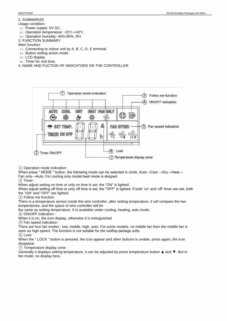
WESTPOINT R410A Rooftop Package Unit 50Hz
2. SUMMARIZE Usage condition: 1○. Power supply: 5V DC. 2○. Operation temperature: -15℃-+43℃. 3○. Operation humidity: 40%-90%, RH. 3. FUNCTION SUMMARY Main function: 1○. Connecting to indoor unit by A, B, C, D, E terminal; 2○. Button setting action mode. 3○. LCD display. 4○. Timer for rest time. 4. NAME AND FUCTION OF INDICATORS ON THE CONTROLLER
① Operation mode indication: When press " MODE " button, the following mode can be selected in circle. Auto→Cool →Dry→Heat→ Fan only→Auto. For cooling only model,heat mode is skipped. ② Timer : When adjust setting on time or only on time is set, the "ON" is lighted. When adjust setting off time or only off time is set, the "OFF" is lighted. If both ‘on’ and ‘off’ timer are set, both the "ON" and "OFF" are lighted. ③ Follow me function: There is a temperature sensor inside the wire controller, after setting temperature, it will compare the two temperatures, and the space of wire controller will be the same as setting temperature. It is available under cooling, heating, auto mode. ④ ON/OFF indication : When it is on, the icon display, otherwise it is extinguished. ⑤ Fan speed indication : There are four fan modes : low, middle, high, auto. For some models, no middle fan then the middle fan is seen as high speed. The function is not suitable for the rooftop package units. ⑥ Lock: When the " LOCK " button is pressed, the icon appear and other buttons is unable, press again, the icon disappear. ⑦ Temperature display zone: Generally it displays setting temperature, it can be adjusted by press temperature button ▲ and ▼. But in fan mode, no display here.
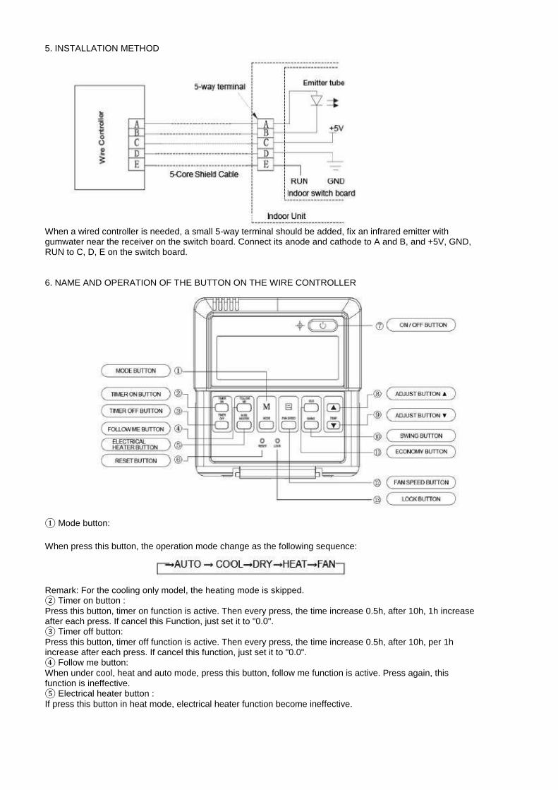
5. INSTALLATION METHOD
When a wired controller is needed, a small 5-way terminal should be added, fix an infrared emitter with gumwater near the receiver on the switch board. Connect its anode and cathode to A and B, and +5V, GND, RUN to C, D, E on the switch board.
6. NAME AND OPERATION OF THE BUTTON ON THE WIRE CONTROLLER
① Mode button:
When press this button, the operation mode change as the following sequence:
Remark: For the cooling only model, the heating mode is skipped. ② Timer on button : Press this button, timer on function is active. Then every press, the time increase 0.5h, after 10h, 1h increase after each press. If cancel this Function, just set it to "0.0". ③ Timer off button: Press this button, timer off function is active. Then every press, the time increase 0.5h, after 10h, per 1h increase after each press. If cancel this function, just set it to "0.0". ④ Follow me button: When under cool, heat and auto mode, press this button, follow me function is active. Press again, this function is ineffective. ⑤ Electrical heater button : If press this button in heat mode, electrical heater function become ineffective.

WESTPOINT R410A Rooftop Package Unit 50Hz ⑥ Reset button(hidden): Use a 1mm stick to press in the little hole , then the current setting is canceled . The wired controller will enter into original state. ⑦ON/OFF button: When in off state, press this button, the indicator is on, the wire controller enter into on state, and send setting information to in door PCB. When in on state, press this button, the indicator is off, and send instruction. If timer on or timer off has been set, it cancel this setting then send instruction to stop the machine. ⑧ Adjust button ▲: Set indoor temperature up. If press and hold on, it will increase at 1 degree per 0.5 second. ⑨ Adjust button ▼ : Set indoor temperature down. If press and hold on, it will decrease at 1degree per 0.5 second. ⑩ Swing button: First pressing: start swing function; second pressing: stop swing. (Match to some model with swing function).
11○ Economy operation button:
Press this button, the indoor unit operates in economy mode, press it again, exit this mode (it may be ineffective for some models)
12○ Fan speed button:
Press this button consecutively, the fan speed will circle as follow:
13○ Lock button (hidden):
When you push the LOCK button, all current settings are locked in and the wire controller does not accept any operation except that of the LOCK button. Use the lock mode when you want to prevent setting from being changed accidentally or play fully. Push the LOCK button again when you want to cancel the LOCK mode.
7. USING METHOD
AUTOMATIC OPERATION Connect to power, indoor operation lamp flash. 1○. Press "MODE" button, select " AUTO " ; 2○. Press the button "▲" and "▼", set temperature you want, generally it is among 17℃~30℃; 3○. Press " ON/OFF" button, operation lamp is on, the air-conditioner work in auto mode, indoor fan is auto, and cannot be changed. Auto is displayed on LCD. Press " ON/OFF" button again to stop. 4○. Economy operation is valid in auto mode. COOL/HEAT/FAN MODE OPERATION 1○. Press "MODE" button, select "COOL", "HEAT" or "FAN ONLY" mode. 2○. Press temperature adjust button to select setting temp.. 3○. Press "FAN SPEED" button to select high/mid/low/auto. 4○. Press "ON/OFF" button, indoor unit operation lamp on, it works in selected mode. Press "ON/OFF" button again, it stops to work. Remark: When in fan mode, no temperature can be set.
DRY OPERATION
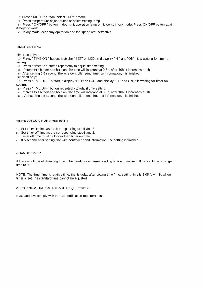
1○. Press " MODE " button, select " DRY " mode. 2○. Press temperature adjust button to select setting temp. 3○. Press " ON/OFF " button, indoor unit operation lamp on, it works in dry mode. Press ON/OFF button again, it stops to work. 4○. In dry mode, economy operation and fan speed are ineffective.
TIMER SETTING
Timer on only: 1○. Press " TIME ON " button, it display "SET" on LCD, and display " H " and "ON" , it is waiting for timer on setting. 2○. Press " timer " on button repeatedly to adjust time setting. 3○. If press this button and hold on, the time will increase at 0.5h, after 10h, it increases at 1h. 4○. After setting 0.5 second, the wire controller send timer on information, it is finished. Timer off only: 1○. Press "TIME OFF " button, it display "SET" on LCD, and display " H " and ON, it is waiting for timer on setting. 2○. Press "TIME OFF" button repeatedly to adjust time setting. 3○. If press this button and hold on, the time will increase at 0.5h, after 10h, it increases at 1h. 4○. After setting 0.5 second, the wire controller send timer off information, it is finished.
TIMER ON AND TIMER OFF BOTH
1○. Set timer on time as the corresponding step1 and 2. 2○. Set timer off time as the corresponding step1 and 2. 3○. Timer off time must be longer than timer on time. 4○. 0.5 second after setting, the wire controller send information, the setting is finished.
CHANGE TIMER
If there is a timer of changing time to be need, press corresponding button to revise it. If cancel timer, change time to 0.0.
NOTE: The timer time is relative time, that is delay after setting time ( i, e: setting time is 8:05 A,M). So when timer is set, the standard time cannot be adjusted.
8. TECHNICAL INDICATION AND REQUIREMENT
EMC and EMI comply with the CE certification requirements.
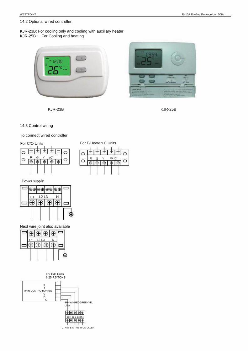
WESTPOINT R410A Rooftop Package Unit 50Hz
14.2 Optional wired controller:
KJR-23B: For cooling only and cooling with auxiliary heater KJR-25B: For Cooling and heating
KJR-23B KJR-25B
14.3 Control wiring
To connect wired controller
For C/O Units
R
For E/Heater+C Units
G Y (C) R G Y W (C)
Power supply
L1 L2 L3 N
Next wire joint also available
L1 L2 L3 N
For C/O Units 6.25-7.5 TONS
B Y MAIN CONTRO BOARDL G R C
TOTH W E C TRE IR ON OLLER
BROWNREDGREENYELLOW
C R G Y B XT4

Suggestion: Thermostat choose KJR-23B or Non-programmed electrical thermostat series of Honeywell, such as TH5220D. Wiring please refer to the Owner’s Manual of the thermostat. Dial code setting Set the dial code SW3 of PCB in unit’s wire control box, after settings, please shut off the power supply and then repower, otherwise, the new settings function couldn’t work. When select the KJR-12B wired controller, please set the SW3 in “ON”. When select the wired controller be recommended, please set the SW3 in”1”.
For C/O Units 8.5-30 TONS
KJR -1 2B
A B
C D
5 -termi na l Gro up BROW N
RED Y ELLOW BL ACK WH ITE
CN9 CN36
ON SW3
1 CN7 GREEN WHITE RED YELLOW
MAIN CONTROL BOARD
E R G Y (C) XT2
TOTHE WIRE CONTROLLER
For E/Heater+C Units
5 -termi na l KJR -1 2B Gro up
BROW N ON
A B
C D
SW3 1 RED
Y ELLOW BL ACK WH ITE
CN7 BLUEWHITE RED YELLOW
CN9 MAIN CONTROL BOARD
CN36 GREEN E
R G Y W(C) XT2
TOTHE WIRE CONTROLLER

WESTPOINT R410A Rooftop Package Unit 50Hz
15. Error Code
15.1 Error Code for 6.2&7.5ton
NUM CODE
1 STANDBY
2 FUNCTION
PHASE-MISSING
3 PHASE-ERROR
T1 SENSOR FAILURE
4 HIGH PRESSURE PROTECTION
VENT PROTECTION
5 T2 SENSOR FAILURE
6 7
8
9
10
11
12
T3 SENSOR FAILURE T4 SENSOR FAILURE
T2 EVAPORATOR LOWTEMP. PROTECTION
T2 EVAPORATOR HIGH TEMP. PROTECTION
T3 CONDENSOR HIGH TEMP. PROTECTION
LINE CONTROLLER INPUT FAILURE
COMPRESSOR OVERCURRENT PROTECTION
COMPRESSOR-INHALING LOW
PRESSURE PROTECTION
DEFROST
LED1(RED) OFF
ON
FLASH
FLASH
FLASH
OFF ON
OFF
FLASH
FLASH
FLASH
OFF
FLASH ON
LED2(YELLOW) OFF
ON
FLASH
FLASH
OFF
FLASH FLASH
FLASH
ON
OFF
FLASH
OFF
ON FLASH
LED3(GREEN) ON
ON
FLASH
FLASH
FLASH
FLASH FLASH
OFF
ON
OFF
ON
FLASH
FLASH FLASH
13 14

Error code for8.5ton and above

WESTPOINT R410A Rooftop Package Unit 50Hz
15.2 Troubleshooting
1○E0:Compressor phase sequence error or phase default
Detect if the voltage of 5p wire joint between A, B and C is normal.
No
Cut off power supply, replace the Yes
power wire, inspect again. Detect if the main board voltage between A, B and C is normal.
No Yes
Cut off power supply, exchange the Cut off power supply, exchange freely two wires between A, B and C. Power on again, if the main board display E0.
wire from main power supply to main board. Power on again, retesting.
No
Yes OK.
Replace the main board.
2○E1:Outdoor coil temp. sensor T3 default.
Detect if the temp. sensor is normal.
Yes
Replace the main board.
No
Replace the temp. sensor, detect it again.

3○ E9:Indoor coil temp. sensor T2 default.
(Indoor temp. and Pipe Temp. Sensor Resistance Value Table, see Appendix 2 )
Detect if the temp. sensor is normal.
Yes
Replace the main board.
No
Replace the temp. sensor, detect it again.
4○When E2,E5,E6 or EA displays, please check the wired nameplate, if the terminals of T2_1、T2_2、
T3_2、T4 are connected as short circuit. If no, please connect all as short circuit, unless replace main board.
5○Eb: Wired controller output error.(Only for KJR-23B or KJR-25B).
Avoid three conditions as following: 1) The wired controller output signal has Y, no G. 2) The wired controller output signal has W, no G. 3) The wired controller output signal has Y and W, no G.
6○P0:Compressor over current protection.(The over current protection value is 16A)
Detect B phase current, if the current value is over the setting value.
No
Replace the main board. Yes
The main board display P0, normal.
7○P3:Comprehensive protection for outdoor fan
Detect if the three-phase protector display is normal.
No The main board display P3, normal.
Yes
Detect by multimeter if three-phase protector COM and NO exist current circuit.
No Replace three-phase protector, detect it again.
Yes
Replace the main board.

WESTPOINT R410A Rooftop Package Unit 50Hz
8Protection for Hi./Lo. Pressure or exhaust temp. (High pressure protection value:4.4MPa, High○P4:
pressure protection value:0.14MPa;air discharge temp. protection value: 130℃ above)
When P4 display, detect Hi/Lo pressure testing point by pressure gauge and discharge point temp. by thermometer. Conform if all testing values are normal.
No The main board display P4 is normal.
Yes
Detect by multimeter if the high/low pressure switch two sides and air discharge switch two sides exist current circuit.
Replace high/low pressure switch No and air discharge temp. switch,
detect them again.
Yes
Replace the main board.
9○Indoor fan motor don’t work.
Detect if there exist current from main board to indoor fan.
No Replace the main board.
Yes
No Replace indoor fan capacitor, detect it again, conform if the indoor fan works.
Replace the indoor fan.
Yes
Remove the problem
10○ Outdoor fan motor don’t work.
Detect if there exist power supply from main board to outdoor fan.
No Replace the main board.
Yes
Replace the capacitor of outdoor fan, detect it again, if the outdoor fan work.
No Replace outdoor fan.
Yes
Remove the problem

1○ Indoor fan motor don’t run.
The first check if the power supplier is normal, if all wire connection terminal is loose, if the wired controller set and wire connection are correct, operating as flow process after confirm.
If the heating mode is in preventing cold state for a long time (Cooling mode will not be considered)
No
Detect if the voltage of the fan on PCB which corresponds to the interface is 208 ~ 230V AC between CN6 of INFAN and N.
Yes
Replace T2 sensor or check if exist leakage in pipeline.
Yes No
If the indoor fan contactor is close. Detect if the fuse on PCB is burned off.
Yes No Yes No
Check if the secondary voltage transformer is normal.
Replace motor. Replace contactor. Replace fuse.
Yes No
Replace PCB. Replace transformer.

WESTPOINT R410A Rooftop Package Unit 50Hz
2○ Compressor don’t run (All wires connection are correct and reliable, if power supplier is required
range. If compressor don’t run, you can analysis as flowing)
Detect if the voltage of compressor which corresponds to the interface on PCB is 208 ~ 230V AC between CN6 of COMP1, COMP2 and N.
Yes No
If indoor fan motor contactor is close.
Detect if the fuse on PCB is burned off.
Yes No Yes No
Replace compressor.
Replace contactor.
Replace fuse. Check if the secondary voltage transformer is normal.
Yes
Replace
No
Replace transformer.
3○ T3 temp sensor error.
Is the electric resistance of T3 answer for Appendix 1?
PCB.
Yes
Replace PCB.
No
Replace the T3 sensor.
4○ Check if the low pressure protection is normal.
Check if the low pressure protection is normal (The normal resistance is 0Ω).
Yes
Replace PCB.
No
1:Check if the refrigerant in system is less. 2:Detect if system have blocked 3:Check if the four-valve is broken. 4:Detect if low-pressure switching ontology is bad, replace the low-voltage switch.

5○ Outdoor fan motor don’t run.
Detect if the voltage of compressor which corresponds to the interface on PCB is 208 ~ 230V AC between CN6 of OFAN1,OFAN2 and N.
Yes No
If the outdoor fan motor contactor is close.
Detect if the fuse on PCB is burned off.
Yes
Replace outdoor fan motor.
No
Replace contactor.
Yes
Replace fuse.
No
Check if the secondary voltage transformer is normal.
Yes No
Replace transformer.
Replace PCB.
6○ Four ways valve don’t work.
Detect if the voltage is 208 ~ 230V AC between CN28, CN29 and C on PCB.
Yes
Replace four way valve or coil.
No
Detect if the fuse on PCB is burned off.
Yes
Replace fuse.
No
Check if the secondary voltage transformer is normal.
Yes
Replace PCB.
No
Replace transformer.
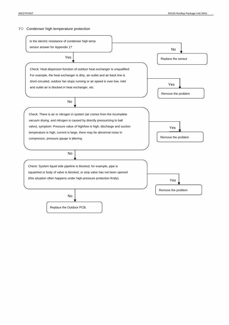
WESTPOINT R410A Rooftop Package Unit 50Hz
7○ Condenser high temperature protection
Is the electric resistance of condenser high temp sensor answer for Appendix 1?
No
Replace the sensor Yes
Check: Heat dispersion function of outdoor heat exchanger is unqualified: For example, the heat exchanger is dirty, air-outlet and air-back line is short-circuited, outdoor fan stops running or air speed is over-low, inlet and outlet air is blocked in heat exchanger, etc.
Yes
Remove the problem
No
Check: There is air or nitrogen in system (air comes from the incomplete vacuum drying, and nitrogen is caused by directly pressurizing to ball valve), symptom: Pressure value of high/low is high, discharge and suction temperature is high, current is large, there may be abnormal noise in compressor, pressure gauge is jittering. Remove the problem
Yes
No
Check: System liquid side pipeline is blocked, for example, pipe is squashed or body of valve is blocked, or stop valve has not been opened (this situation often happens under high-pressure protection firstly).
Yes
Remove the problem No
Replace the Outdoor PCB.
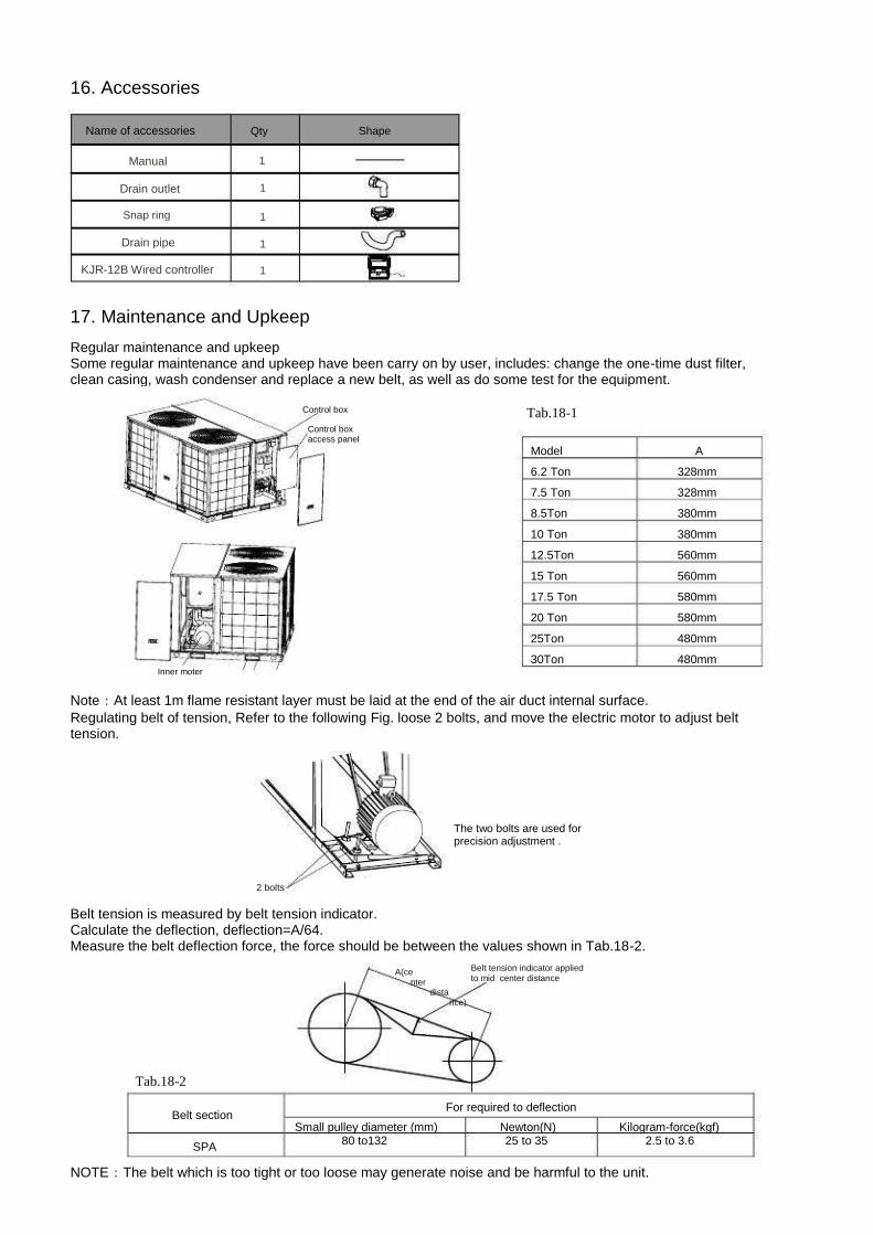
16. Accessories
Name of accessories
Manual
Drain outlet
Snap ring
Qty
1
1
1
1
1
Shape
Drain pipe
KJR-12B Wired controller
17. Maintenance and Upkeep
Regular maintenance and upkeep Some regular maintenance and upkeep have been carry on by user, includes: change the one-time dust filter, clean casing, wash condenser and replace a new belt, as well as do some test for the equipment.
Control box Control box access panel
Tab.18-1
Model 6.2 Ton 7.5 Ton 8.5Ton 10 Ton 12.5Ton 15 Ton 17.5 Ton 20 Ton 25Ton 30Ton
A 328mm 328mm 380mm 380mm 560mm 560mm 580mm 580mm 480mm 480mm
Inner moter
Note:At least 1m flame resistant layer must be laid at the end of the air duct internal surface. Regulating belt of tension, Refer to the following Fig. loose 2 bolts, and move the electric motor to adjust belt tension.
The two bolts are used for precision adjustment .
2 bolts
Belt tension is measured by belt tension indicator. Calculate the deflection, deflection=A/64. Measure the belt deflection force, the force should be between the values shown in Tab.18-2.
A(ce nter dista nce)
Belt tension indicator applied to mid_center distance
Tab.18-2
Belt section
SPA
For required to deflection Small pulley diameter (mm) 80 to132
Newton(N) 25 to 35
Kilogram-force(kgf) 2.5 to 3.6
NOTE:The belt which is too tight or too loose may generate noise and be harmful to the unit.

WESTPOINT R410A Rooftop Package Unit 50Hz
Appendix :
1. Indoor Temp. and Pipe Temp. Sensor Resistance Value Table (8.5ton and above)
℃
-20 -19 -18 -17 -16 -15 -14 -13 -12 -11 -10 -9 -8 -7 -6 -5 -4 -3 -2 -1 0 1 2 3 4 5 6 7 8 9
10 11 12 13 14 15 16 17 18 19
K Ohm 115.266 108.146 101.517 96.3423 89.5865 84.2190 79.3110 74.5360 70.1698 66.0898 62.2756 58.7079 56.3694 52.2438 49.3161 46.5725 44.0000 41.5878 39.8239 37.1988 35.2024 33.3269 31.5635 29.9058 28.3459 26.8778 25.4954 24.1932 22.5662 21.8094 20.7184 19.6891 18.7177 17.8005 16.9341 16.1156 15.3418 14.6181 13.9180 13.2631
℃
20 21 22 23 24 25 26 27 28 29 30 31 32 33 34 35 36 37 38 39 40 41 42 43 44 45 46 47 48 49 50 51 52 53 54 55 56 57 58 59
K Ohm 12.6431 12.0561 11.5000 10.9731 10.4736 10.000
9.55074 9.12445 8.71983 8.33566 7.97078 7.62411 7.29464 6.98142 6.68355 6.40021 6.13059 5.87359 5.62961 5.39689 5.17519 4.96392 4.76253 4.57050 4.38736 4.21263 4.04589 3.88673 3.73476 3.58962 3.45097 3.31847 3.19183 3.07075 2.95896 2.84421 2.73823 2.63682 2.53973 2.44677
℃
60 61 62 63 64 65 66 67 68 69 70 71 72 73 74 75 76 77 78 79 80 81 82 83 84 85 86 87 88 89 90 91 92 93 94 95 96 97 98 99
K Ohm 2.35774 2.27249 2.19073 2.11241 2.03732 1.96532 1.89627 1.83003 1.76647 1.70547 1.64691 1.59068 1.53668 1.48481 1.43498 1.38703 1.34105 1.29078 1.25423 1.21330 1.17393 1.13604 1.09958 1.06448 1.03069 0.99815 0.96681 0.93662 0.90753 0.87950 0.85248 0.82643 0.80132 0.77709 0.75373 0.73119 0.70944 0.68844 0.66818 0.64862
℃
100 101 102 103 104 105 106 107 108 109 110 111 112 113 114 115 116 117 118 119 120 121 122 123 124 125 126 127 128 129 130 131 132 133 134 135 136 137 138 139
K Ohm 0.62973 0.61148 0.59386 0.57683 0.56038 0.54448 0.52912 0.51426 0.49989 0.48600 0.47256 0.45957 0.44699 0.43482 0.42304 0.41164 0.40060 0.38991 0.37956 0.36954 0.35982 0.35042 0.3413
0.33246 0.32390 0.31559 0.30754 0.29974 0.29216 0.28482 0.27770 0.27078 0.26408 0.25757 0.25125 0.24512 0.23916 0.23338 0.22776 0.22231

2. Indoor Temp. and Pipe Temp. Sensor Resistance Value Table (6.2&7.5ton) Temp
(℃)
-20 -19 -18 -17 -16 -15 -14 -13 -12 -11 -10 -9 -8 -7 -6 -5 -4 -3 -2 -1 0 1 2 3 4 5 6 7 8 9
10 11 12 13 14 15 16 17 18 19 20 21 22 23 24 25 26 27 28
Rmax
116.539 110.231 103.743 97.673 91.990 86.669 81.684 77.013 72.632 68.523 64.668 61.048 57.649 54.456 51.456 48.636 45.984 43.490 41.144 38.935 36.857 34.898 33.055 31.317 29.681 28.138 26.682 25.310 24.016 22.794 21.641 20.553 19.525 18.554 17.636 16.769 15.949 15.174 14.442 13.748 13.093 12.471 11.883 11.327 10.800 10.300 9.848 9.418 9.010
Resistance(KΩ)
R(t)Normal
106.732 100.552 94.769 89.353 84.278 79.521 75.059 70.873 66.943 63.252 59.784 56.524 53.458 50.575 47.862 45.308 42.903 40.638 38.504 36.492 34.596 32.807 31.120 29.528 28.026 26.608 25.268 24.003 22.808 21.678 20.610 19.601 18.646 17.743 16.888 16.079 15.313 14.588 13.902 13.251 12.635 12.050 11.496 10.971 10.473 10.000 9.551 9.125 8.721
Rmin
96.920 91.451 86.328 81.525 77.017 72.788 68.815 65.083 61.574 58.274 55.169 52.246 49.492 46.899 44.455 42.150 39.977 37.927 35.992 34.165 32.440 30.810 29.271 27.815 26.440 25.140 23.909 22.745 21.644 20.601 19.614 18.680 17.794 16.955 16.160 15.406 14.691 14.014 13.372 12.762 12.183 11.634 11.112 10.617 10.147 9.700 9.255 8.834 8.434
Resist.tol (%)
MAX(+)
9.19 9.63 9.47 9.31 9.15 8.99 8.83 8.66 8.50 8.33 8.17 8.00 7.84 7.67 7.51 7.35 7.18 7.02 6.86 6.70 6.53 6.38 6.22 6.06 5.90 5.75 5.60 5.45 5.30 5.15 5.00 4.86 4.71 4.57 4.43 4.29 4.15 4.02 3.89 3.75 3.62 3.50 3.37 3.25 3.12 3.00 3.11 3.21 3.31
MIN(-)
9.19 9.05 8.91 8.76 8.62 8.47 8.32 8.17 8.02 7.87 7.72 7.57 7.42 7.27 7.12 6.97 6.82 6.67 6.52 6.38 6.23 6.09 5.94 5.80 5.66 5.52 5.38 5.24 5.10 4.97 4.83 4.70 4.57 4.44 4.31 4.19 4.06 3.94 3.81 3.69 3.57 3.46 3.34 3.23 3.11 3.00 3.10 3.19 3.29
Temp.tol(℃)
MAX(+)
1.59 1.57 1.56 1.54 1.53 1.51 1.49 1.47 1.45 1.44 1.42 1.40 1.38 1.35 1.33 1.31 1.29 1.27 1.25 1.23 1.21 1.18 1.16 1.14 1.12 1.10 1.07 1.05 1.03 1.01 0.99 0.96 0.94 0.92 0.90 0.88 0.86 0.84 0.81 0.79 0.77 0.75 0.73 0.71 0.69 0.67 0.69 0.72 0.75
MIN(-)
1.59 1.57 1.55 1.54 1.52 1.50 1.48 1.47 1.45 1.43 1.41 1.39 1.37 1.35 1.32 1.30 1.28 1.26 1.24 1.21 1.19 1.17 1.15 1.12 1.10 1.08 1.06 1.03 1.01 0.99 0.97 0.94 0.92 0.90 0.88 0.85 0.83 0.81 0.79 0.76 0.74 0.72 0.70 0.68 0.66 0.63 0.66 0.69 0.71

WESTPOINT R410A Rooftop Package Unit 50Hz
29 30 31 32 33 34 35 36 37 38 39 40 41 42 43 44 45 46 47 48 49 50 51 52 53 54 55 56 57 58 59 60 61 62 63 64 65 66 67 68 69 70 71 72 73 74 75
8.621 8.252 7.900 7.566 7.247 6.944 6.656 6.381 6.119 5.870 5.631 5.404 5.188 4.982 4.785 4.596 4.417 4.246 4.082 3.925 3.776 3.632 3.495 3.363 3.237 3.116 3.001 2.890 2.784 2.682 2.585 2.491 2.401 2.315 2.233 2.154 2.077 2.004 1.934 1.867 1.802 1.740 1.680 1.622 1.567 1.514 1.463
8.337 7.972 7.625 7.296 6.982 6.684 6.401 6.131 5.874 5.630 5.397 5.175 4.964 4.763 4.571 4.387 4.213 4.046 3.887 3.735 3.590 3.451 3.318 3.191 3.069 2.952 2.841 2.734 2.632 2.534 2.440 2.350 2.264 2.181 2.102 2.026 1.953 1.883 1.816 1.752 1.690 1.631 1.574 1.519 1.466 1.416 1.367
8.055 7.695 7.353 7.029 6.721 6.428 6.150 5.886 5.634 5.395 5.167 4.951 4.745 4.549 4.362 4.183 4.014 3.851 3.697 3.550 3.409 3.274 3.146 3.023 2.905 2.793 2.685 2.582 2.484 2.390 2.299 2.213 2.130 2.051 1.975 1.903 1.833 1.766 1.702 1.641 1.582 1.525 1.471 1.419 1.369 1.321 1.275
3.41 3.51 3.61 3.70 3.80 3.89 3.98 4.08 4.17 4.26 4.34 4.43 4.52 4.60 4.69 4.77 4.85 4.93 5.02 5.10 5.18 5.25 5.33 5.41 5.49 5.56 5.64 5.71 5.79 5.86 5.93 6.01 6.08 6.15 6.22 6.29 6.36 6.42 6.49 6.56 6.62 6.69 6.75 6.82 6.88 6.94 7.00
3.38 3.47 3.57 3.66 3.74 3.83 3.92 4.00 4.09 4.17 4.26 4.34 4.42 4.50 4.58 4.66 4.74 4.81 4.89 4.97 5.04 5.12 5.19 5.26 5.34 5.41 5.48 5.55 5.62 5.69 5.76 5.83 5.90 5.96 6.03 6.10 6.16 6.23 6.29 6.35 6.41 6.48 6.54 6.60 6.66 6.71 6.77
0.77 0.80 0.83 0.85 0.88 0.91 0.93 0.96 0.98 1.01 1.03 1.06 1.09 1.12 1.14 1.17 1.19 1.22 1.25 1.28 1.30 1.33 1.35 1.41 1.43 1.46 1.48 1.51 1.54 1.56 1.59 1.62 1.64 1.67 1.70 1.72 1.75 1.77 1.80 1.83 1.85 1.88 1.91 1.93 1.96 1.98 2.01
0.74 0.77 0.79 0.82 0.84 0.87 0.90 0.93 0.95 0.98 1.01 1.03 1.06 1.09 1.12 1.14 1.17 1.20 1.23 1.25 1.28 1.30 1.33 1.36 1.38 1.41 1.44 1.46 1.49 1.52 1.54 1.57 1.60 1.62 1.65 1.68 1.70 1.73 1.76 1.78 1.81 1.84 1.86 1.89 1.92 1.94 1.97

Thanks for buying this new WESTPOINT® air conditioner . Please keep this instruction manual in a safe place.
Nous vous remercions pour le choix de ce climatiseur WESTPOINT®. Veuillez conserver précieusement ce manuel d’utilisation.
Le agradecemos por la elección de este acondicionador de aire WESTPOINT®. Por favor, conserve preciosamente este manual de utilización.
WESTPOINT® اءلشر منتجات شكرا يرجى الحفاظ على دليل التعليمات في مكان آمن.
Specifications are subject to possible modifications without prior notice. Les présentes spécifications sont susceptibles d'être modifiées sans préavis. Las especificaciones estàn sujetas a cambios sin previo aviso