of plate-type heat exchangers - apex group...1 status of development of plate-type heat exchangers...
TRANSCRIPT

1
STATUS OF DEVELOPMENT
OF
PLATE-TYPE HEAT EXCHANGERS FOR
HEAVY-DUTY APLICATIONS
Mircea Dinulescu
APEX International Holding,
Voorburg, The Netherlands
© Mircea Dinulescu – Calgary 2011

2
HEAVY-DUTY APLICATIONS
• Corrosive gases from industrial processes
• Long operating periods without shut down
• High effectiveness
• Operating close to cold-end corrosion point
• Very large volumes of gas
© Mircea Dinulescu – Calgary 2011

3
LARGE VOLUMES OF GAS Single module
© Mircea Dinulescu – Calgary 2011
4
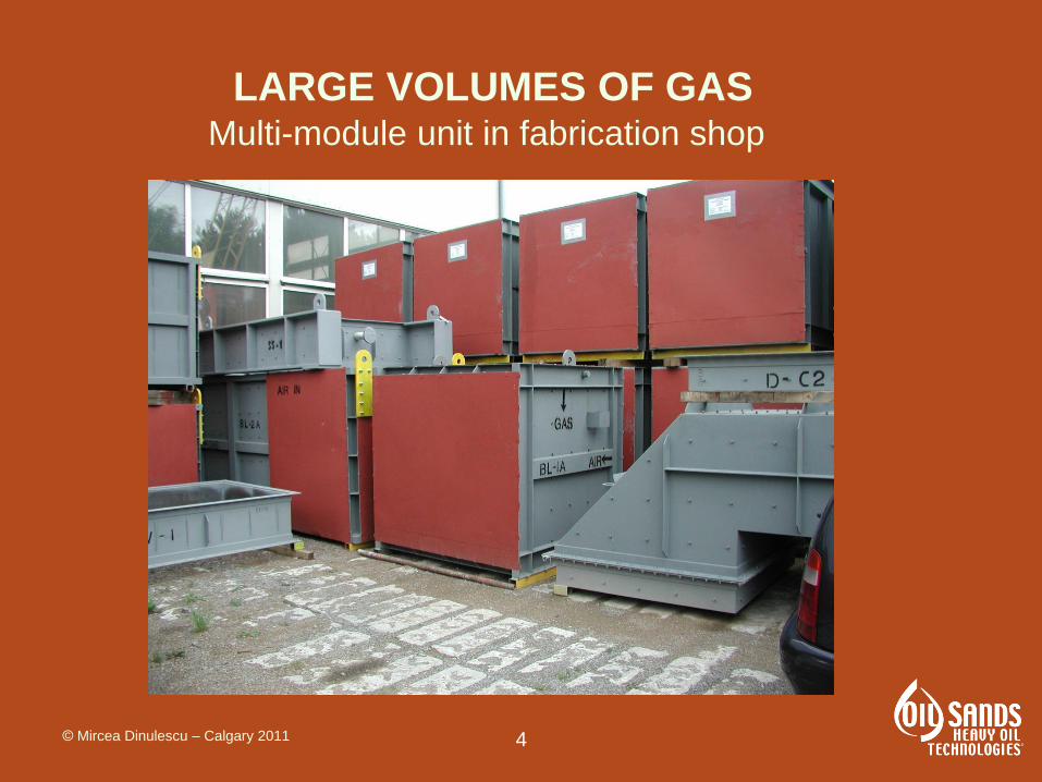
LARGE VOLUMES OF GAS Multi-module unit in fabrication shop
© Mircea Dinulescu – Calgary 2011
5
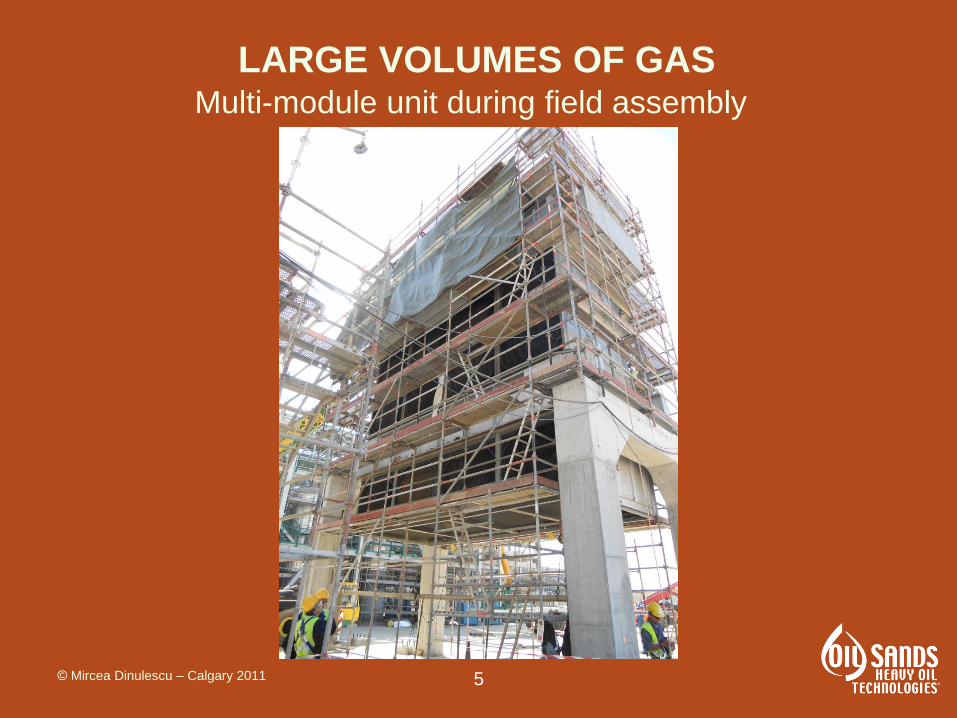
LARGE VOLUMES OF GAS Multi-module unit during field assembly
© Mircea Dinulescu – Calgary 2011

6
HISTORICAL BACKGROUND
• Over 60 years of industrial experience
• Numerous geometries have been developed
Geometries can be classified as:
- enhanced heat transfer geometries
- plain, smooth surfaces
NOTE: Tubular products are not included in
this analysis
© Mircea Dinulescu – Calgary 2011

7
HISTORICAL BACKGROUND
1. Enhanced heat transfer
- After 1950s it was taken for
granted that “enhanced heat
transfer” is the only acceptable
concept
-The related technical literature
exploded after 1960s
- The main aim was to reduce the
heat transfer area at the detriment
of the pumping power
© Mircea Dinulescu – Calgary 2011
8
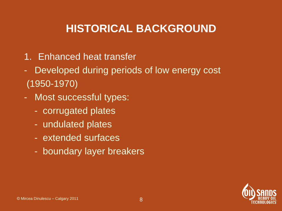
HISTORICAL BACKGROUND
1. Enhanced heat transfer
- Developed during periods of low energy cost
(1950-1970)
- Most successful types:
- corrugated plates
- undulated plates
- extended surfaces
- boundary layer breakers
© Mircea Dinulescu – Calgary 2011

9
HISTORICAL BACKGROUND
2. Flat, smooth surfaces
- The author of this article evaluated the basics of heat
transfer based on increased energy costs in 1970s.
- He found out that the flat, smooth surfaces have
distinct advantages
- Based on his studies, industrial applications were
developed in late 1970s
- Over 30 years of applications these exchangers have
proven their advantages and underwent an exponential
growth
© Mircea Dinulescu – Calgary 2011
10
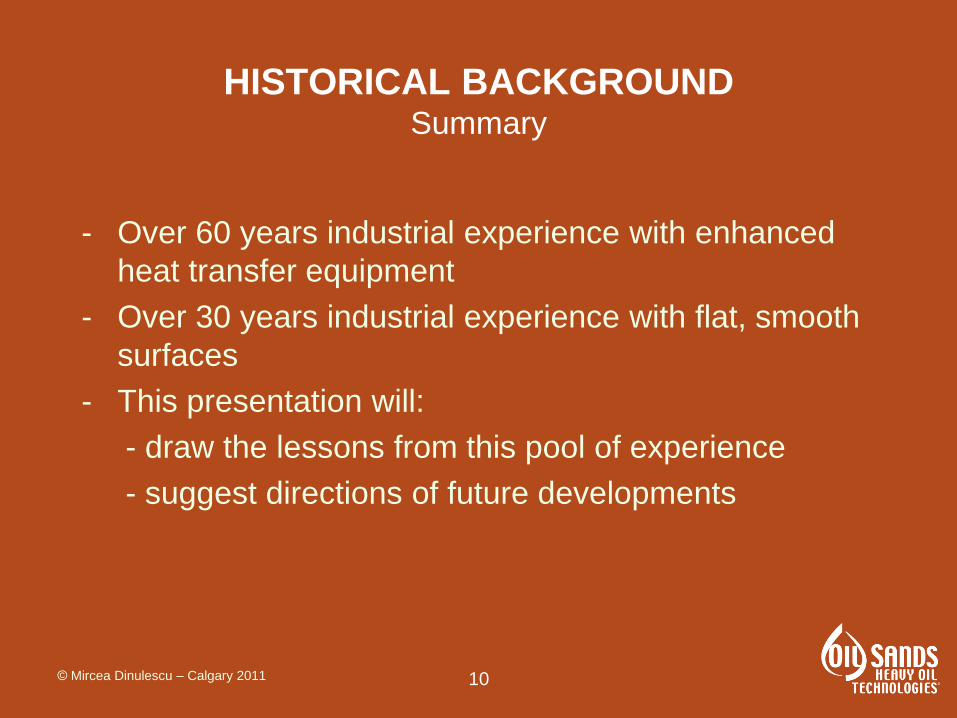
HISTORICAL BACKGROUND Summary
- Over 60 years industrial experience with enhanced
heat transfer equipment
- Over 30 years industrial experience with flat, smooth
surfaces
- This presentation will:
- draw the lessons from this pool of experience
- suggest directions of future developments
© Mircea Dinulescu – Calgary 2011
11
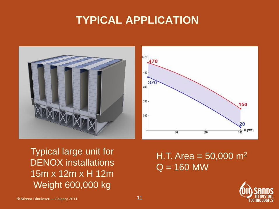
TYPICAL APPLICATION
H.T. Area = 50,000 m2
Q = 160 MW
Typical large unit for
DENOX installations
15m x 12m x H 12m
Weight 600,000 kg
© Mircea Dinulescu – Calgary 2011

12
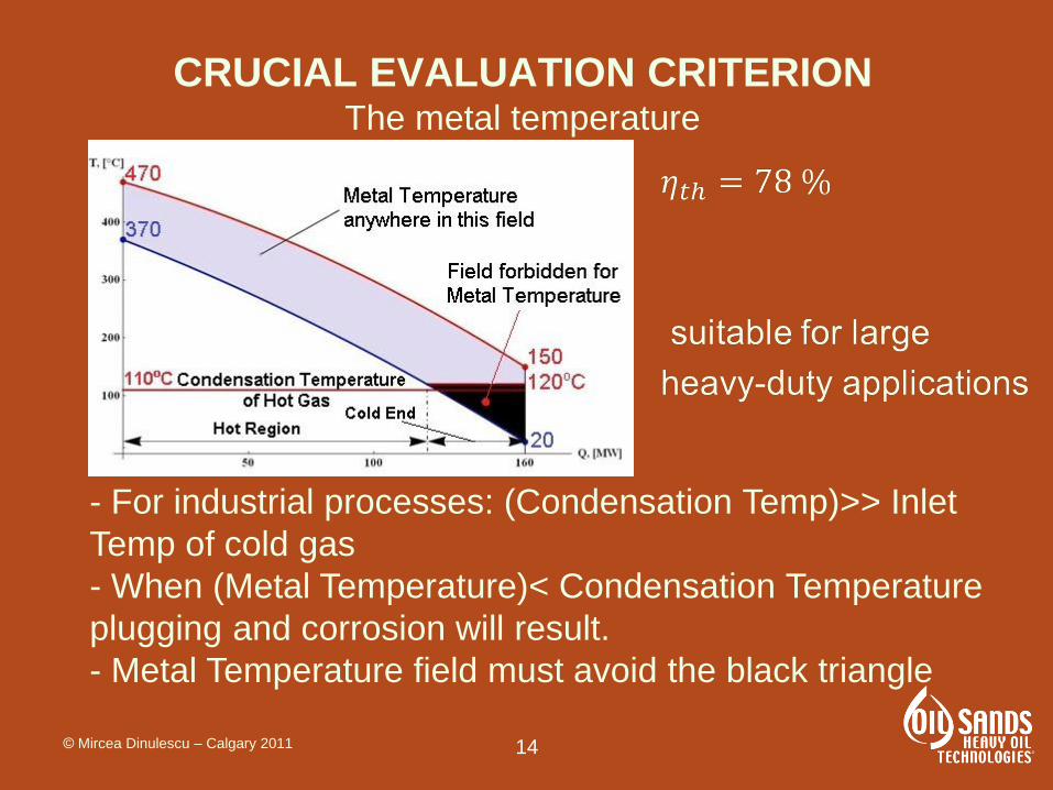
CRUCIAL EVALUATION CRITERION
A diversity of evaluation criteria have been proposed:
- the goodness factor j/f [2]
- evaluation of entropy/exergy formation [5]
- Nue/Nuo vs fe/fo graphs [6]
Based on practical experience, however, we conclude
that a more reliable critical criterion is:
- The Metal Temperature
© Mircea Dinulescu – Calgary 2011

13
CRUCIAL EVALUATION CRITERION The metal temperature
- When (Condensation Temp.)< Inlet Temp. of cold gas
operation is safe: no condensation and no corrosion
- This situation is typical for HVAC (heating, ventilation
and air conditioning)
- Not representative for industrial processes
© Mircea Dinulescu – Calgary 2011
14
CRUCIAL EVALUATION CRITERION The metal temperature
- For industrial processes: (Condensation Temp)>> Inlet
Temp of cold gas
- When (Metal Temperature)< Condensation Temperature
plugging and corrosion will result.
- Metal Temperature field must avoid the black triangle
© Mircea Dinulescu – Calgary 2011
15
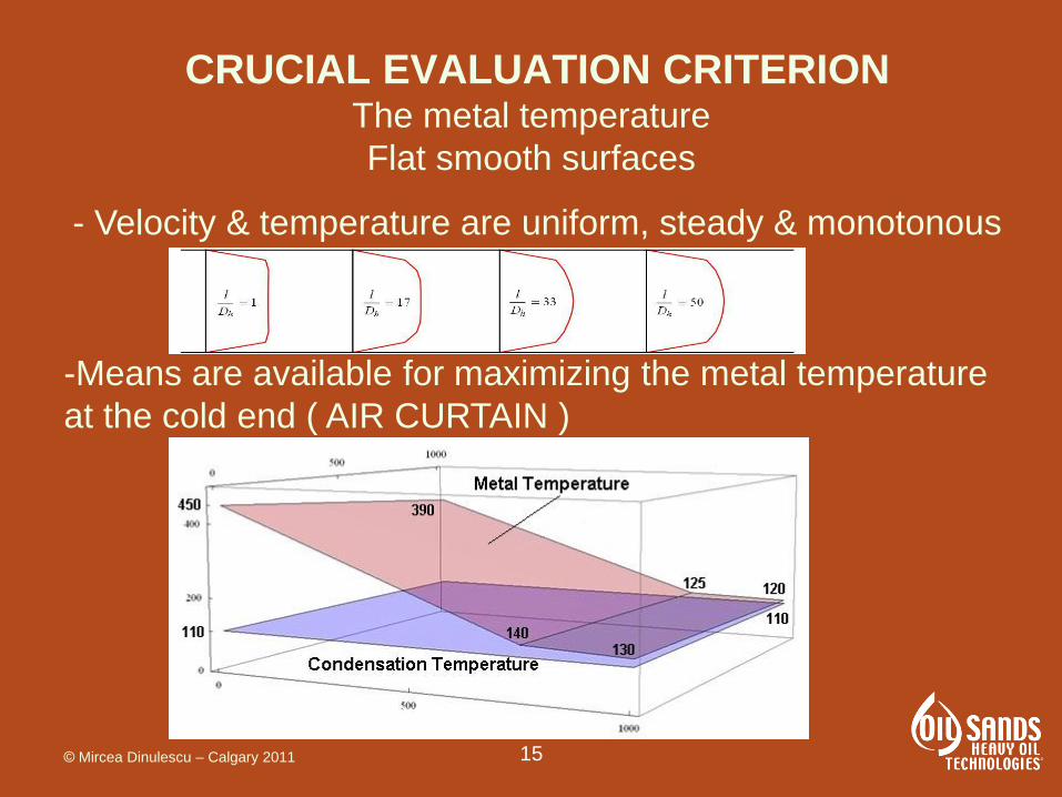
CRUCIAL EVALUATION CRITERION The metal temperature
Flat smooth surfaces
- Velocity & temperature are uniform, steady & monotonous
-Means are available for maximizing the metal temperature
at the cold end ( AIR CURTAIN )
© Mircea Dinulescu – Calgary 2011
16
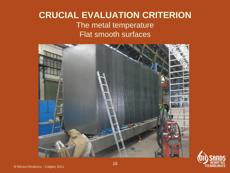
CRUCIAL EVALUATION CRITERION The metal temperature
Flat smooth surfaces
© Mircea Dinulescu – Calgary 2011

17
CRUCIAL EVALUATION CRITERION The metal temperature
Corrugated / undulated surfaces
- Boundary layer is broken at small intervals
- Flow is time dependant , non uniform
- Saw-tooth patterns develop along the flow path
- Stone & Vanka, 1997 report high fluctuations of
temperature & velocity
© Mircea Dinulescu – Calgary 2011

18
CRUCIAL EVALUATION CRITERION The metal temperature
Corrugated / undulated surfaces
-Alawadhi & Bourisli report
saw-tooth Nu distribution
-Mohamed et al report
saw-tooth Nu distribution
© Mircea Dinulescu – Calgary 2011
19
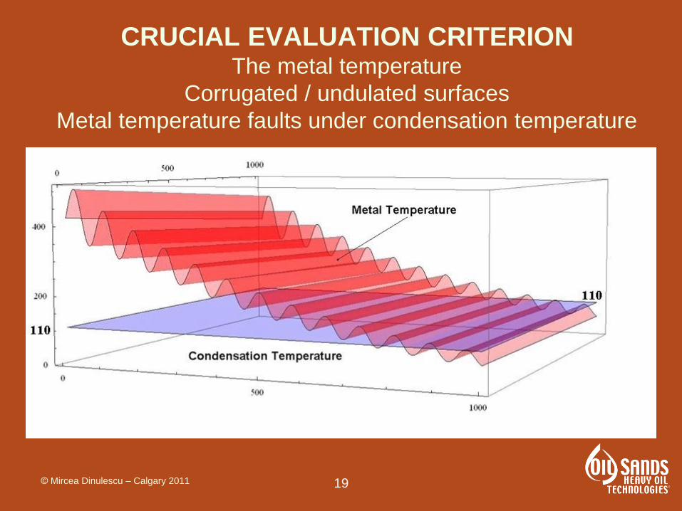
CRUCIAL EVALUATION CRITERION The metal temperature
Corrugated / undulated surfaces
Metal temperature faults under condensation temperature
© Mircea Dinulescu – Calgary 2011
20
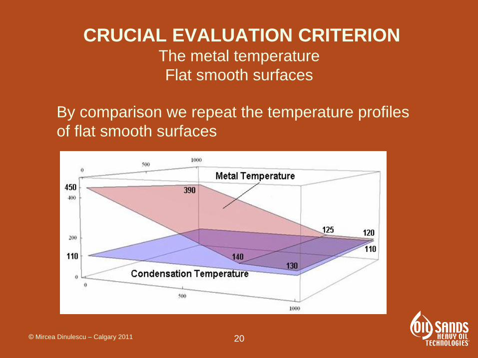
CRUCIAL EVALUATION CRITERION The metal temperature
Flat smooth surfaces
By comparison we repeat the temperature profiles
of flat smooth surfaces
© Mircea Dinulescu – Calgary 2011

21
LESSONS FROM 60 YEARS EXPERIENCE
1. Enhanced transfer concept has played over 60 years
and continues to play an important role.
2. Flat, smooth concept has developed during the last
30 years as a significant alternative with distinct
advantages in the major fields of applications.
2.1. Handling large volumes of gas
2.2. Oil and gas industry
2.3. Power industry
2.4. DENOX installations
© Mircea Dinulescu – Calgary 2011
22
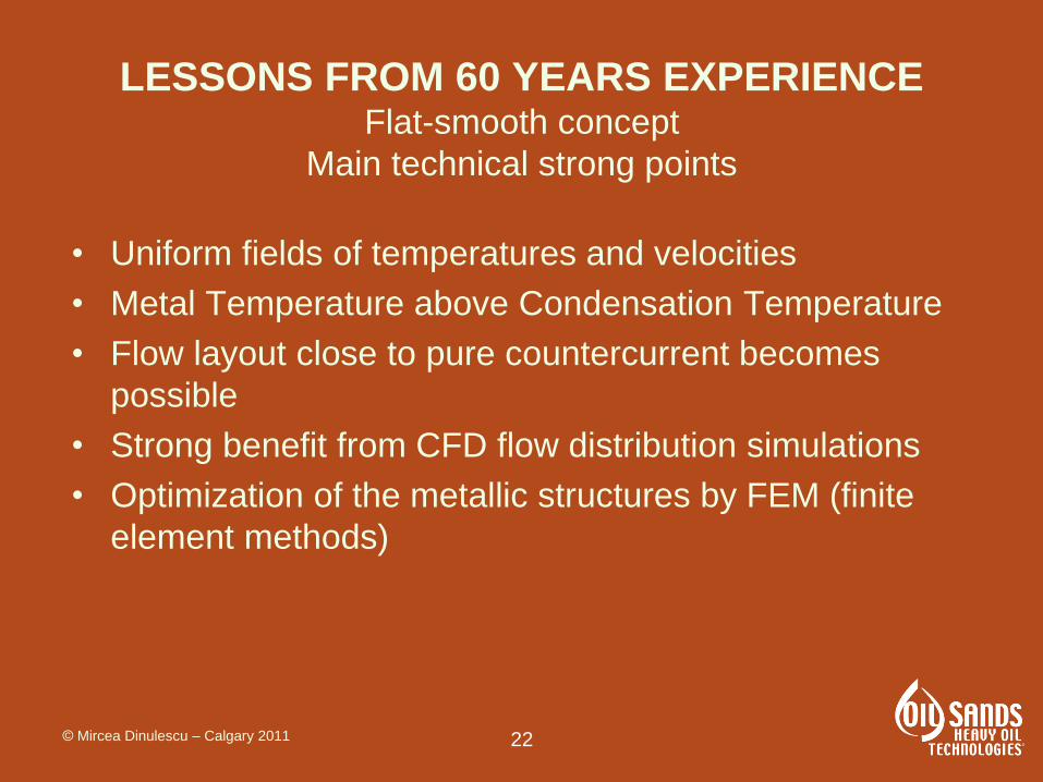
LESSONS FROM 60 YEARS EXPERIENCE Flat-smooth concept
Main technical strong points
• Uniform fields of temperatures and velocities
• Metal Temperature above Condensation Temperature
• Flow layout close to pure countercurrent becomes
possible
• Strong benefit from CFD flow distribution simulations
• Optimization of the metallic structures by FEM (finite
element methods)
© Mircea Dinulescu – Calgary 2011

23
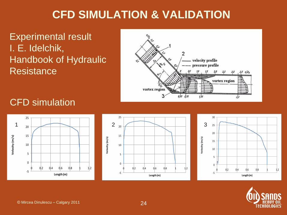
CFD SIMULATION & VALIDATION
Experimental result
I. E. Idelchik,
Handbook of
Hydraulic Resistance
CFD simulation
© Mircea Dinulescu – Calgary 2011
24
CFD SIMULATION & VALIDATION
-5
0
5
10
15
20
25
0 0.2 0.4 0.6 0.8 1 1.2
Ve
loci
ty (
m/
s)
Length (m)
1
-5
0
5
10
15
20
25
0 0.2 0.4 0.6 0.8 1 1.2
Ve
loci
ty (
m/
s)
Length (m)
2
-5
0
5
10
15
20
25
30
0 0.2 0.4 0.6 0.8 1 1.2
Ve
loci
ty (
m/
s)
Length (m)
3
Experimental result
I. E. Idelchik,
Handbook of Hydraulic
Resistance
CFD simulation
© Mircea Dinulescu – Calgary 2011
25
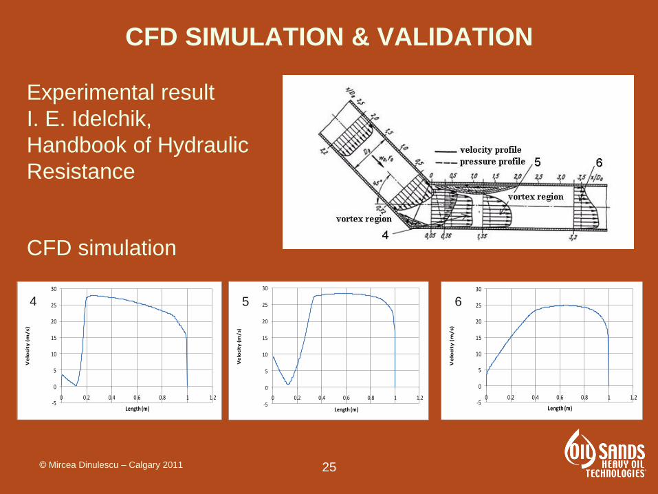
CFD SIMULATION & VALIDATION
-5
0
5
10
15
20
25
30
0 0.2 0.4 0.6 0.8 1 1.2
Ve
loci
ty (
m/
s)
Length (m)
4
-5
0
5
10
15
20
25
30
0 0.2 0.4 0.6 0.8 1 1.2
Ve
loci
ty (
m/
s)
Length (m)
5
-5
0
5
10
15
20
25
30
0 0.2 0.4 0.6 0.8 1 1.2
Ve
loci
ty (
m/
s)
Length (m)
6
Experimental result
I. E. Idelchik,
Handbook of Hydraulic
Resistance
CFD simulation
© Mircea Dinulescu – Calgary 2011

26
CFD SIMULATION & VALIDATION
Experimental result
I. E. Idelchik, Handbook of
Hydraulic Resistance
CFD simulation
© Mircea Dinulescu – Calgary 2011

27
CFD SIMULATION & VALIDATION
CFD simulation details
© Mircea Dinulescu – Calgary 2011

28
CFD SIMULATION & VALIDATION
Flow simulation in a fire heater system
© Mircea Dinulescu – Calgary 2011
29
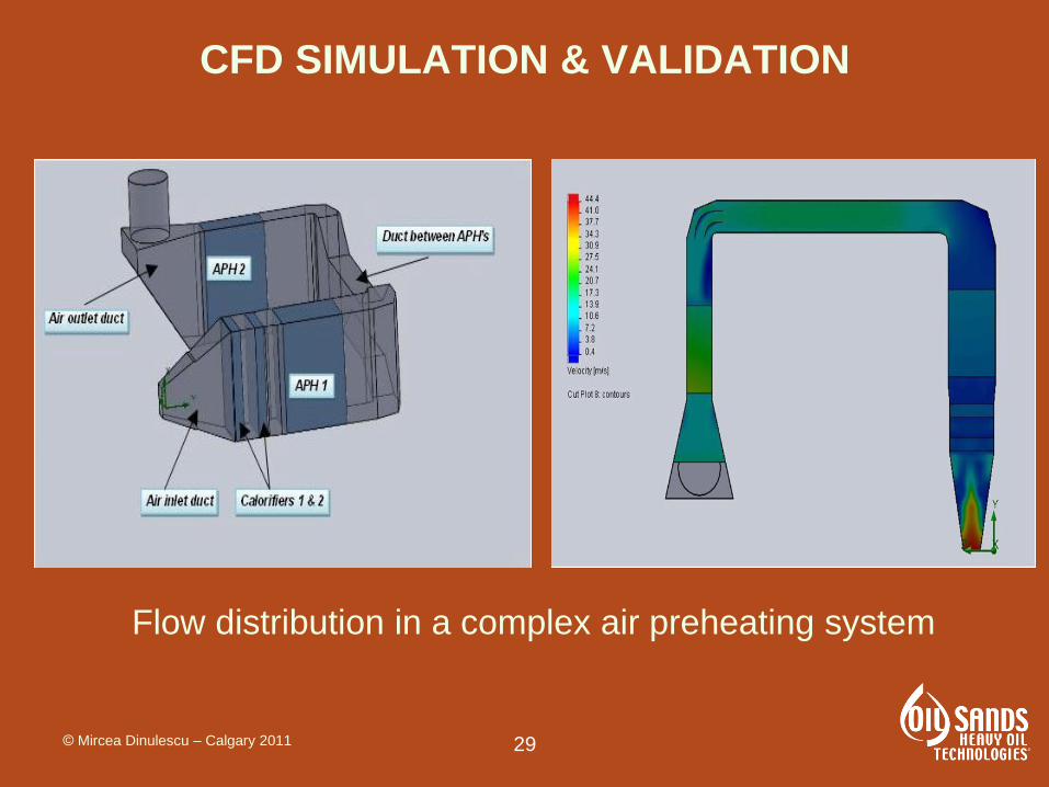
CFD SIMULATION & VALIDATION
Flow distribution in a complex air preheating system
© Mircea Dinulescu – Calgary 2011
30
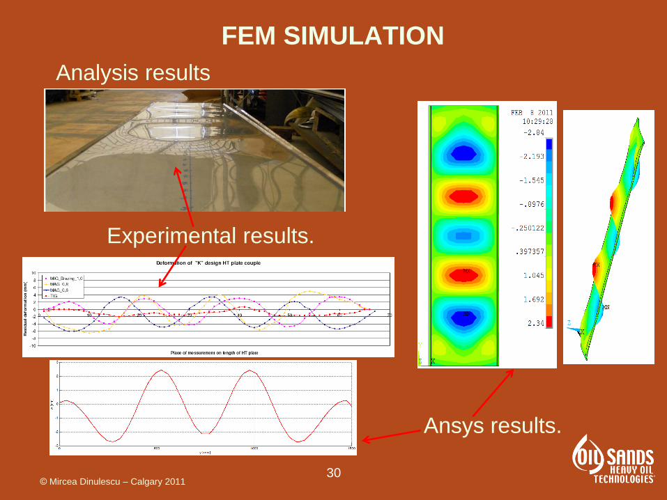
FEM SIMULATION
Ansys results.
Experimental results.
Analysis results
© Mircea Dinulescu – Calgary 2011

31
DIRECTION OF FUTURE DEVELOPMENTS
Very large glass-coated
exchangers
Typical large unit for
glass-coated installation
8m x 10m x H 6m
Weight 200,000 kg
© Mircea Dinulescu – Calgary 2011

32
DIRECTION OF FUTURE DEVELOPMENTS
Near pure countercurrent plug-flow pattern
for high effectiveness units
© Mircea Dinulescu – Calgary 2011

33
DIRECTION OF FUTURE DEVELOPMENTS
Develop the flat-smooth geometry for applications in
new fields:
- Environmental projects
- Bio-mass energy projects
- CO2 subterranean storage
© Mircea Dinulescu – Calgary 2011
34
REFERENCES
[1] I.E. Idelchik, Handbook of Hydraulic Resistence, 3rd ed.
[2] K.M. Stone, S.P. Vanka, Numerical Study of Flow and Heat Transfer in Wary
Passages ACRC TR-118, May 1997
[3] E.M. Alawadhi, R.I. Bourisli, The Role of Periodic Vortex Shedding in Heat
Transfer Enhancement for Transcent Pulsatile Flow Inside Wary Channels,
World Academy of Science, Engineering Technology 46, 2008
[4] Nabou Mohamed et al., Heat Transfer and Flow Field in the Entrance Region
of a Symmetric Wary-Channel with Constant Wall Heat Flux Density, Int.
Journal of Dynamics of Fluids, 1 (2007), pp. 63-79
[5] J.F.Fan, et al. , A performance evaluation plot of enhanced heat transfer
techniques oriented for energy-saving, Int. Journal of Heat and Mass
Transfer, June 2008
[6] N. Sahiti et al. , Strategy for selection of elements of heat transfer
enhancement, Int. Journal of Heat and Mass Transfer 49 (2006)
© Mircea Dinulescu – Calgary 2011
35
Contact Information
• Mircea Dinulescu, Harrie Neefs
• APEX International Holding
• Tel.: +31703004242
© Mircea Dinulescu – Calgary 2011