webmanuals.lennoxeurope.comwebmanuals.lennoxeurope.com/out of production/chillers...dc/lch p - lch v...
TRANSCRIPT
����������������������� ����
���������� �� ����� ����
�������������� ��
����������������������
���
���
DC/LCH P - LCH V • 1 •
Nos produits sont conformes aux normes européennes
Our products comply with the European standards.
AFAQ N° 1993/1009b
SOMMAIRECONTENTS
Présentation et descriptif des composantsIntroduction and description of the components ................................... 3
Tables de performancesPerformance tables
• LCH P ............................................................................... 6
• LCH P R22 .................................................................................. 7
• LCH V ............................................................................... 8
• LCH V R22 ................................................................................. 11
Caractéristiques techniquesTechnical data ..................................................................................... 14
Caractéristiques électriquesElectrical data ...................................................................................... 17
Pertes de charge évaporateursEvaporators pressure drops ................................................................ 18
Caractéristiques dimensionnellesDimensional data ................................................................................ 19
Niveaux sonoresNoise levels ......................................................................................... 22
Limites d'utilisationOperating limits ................................................................................... 23
La fabrication des refroidisseurs LCH P et LCH V répond au système decontrôle qualité ISO 9001. Une copie du certificat peut être obtenue sur simpledemande.
The manufacturing of LCH P & LCH V chillers answers to ISO 9001 controlquality system. A copy of the certificat can be get on request.
Photo couverture :LCH avec option isolation phonique
Cover picture :LCH with noise insulation option

• 2 • DC/LCH P - LCH V
DC/LCH P - LCH V • 3 •
Les refroidisseurs de liquide de la gamme LCH s'intè-grent parfaitement dans notre gamme complète desystème HVAC "Chauffage - Ventilation - Condition-nement d'air".
La fabrication des refroidisseurs LCH P et V estconforme aux normes européennes et répond ausystème de contrôle qualité ISO 9001.
Afin de s'assurer de la conformité finale du produitavec la commande du client et du parfait fonctionne-ment électrique et frigorifique, les refroidisseursLCH P et V sont systématiquement testés en stationd'essai avant leur expédition.
Compacts et silencieux, les refroidisseurs LCH P et Vbénéficient des meilleures technologies pour répon-dre aux exigences de fiabilité et de sécurité.
Ils sont équipés de compresseurs à pistons (LCH P)ou à vis (LCH V) et fonctionnent en standard au R407C(LCH PK et LCH VK).
COMPRESSEUR- Sur LCH P : Type semi-hermétique à pistons- Sur LCH P : Démarrage Part-Winding- Sur LCH V : Type semi-hermétique à vis- Sur LCH V : Démarrage Etoile/Triangle- Sur LCH V : Régulation de puissance 0-50-75-100% par
compresseur- Moteur incorporé refroidi par les gaz aspirés- Résistance de réchauffage carter- Dispositif anti-court cycle- Protection thermique du moteur- Clapet d'aspiration et de refoulement sur LCH V- Clapet de refoulement et silencieux de refoulement sur
LCH P- Vanne d'isolement au refoulement (sur LCH P uniquement)- Montage sur plots antivibratiles en polyéthéruréthane cel-
lulaire haute efficacité
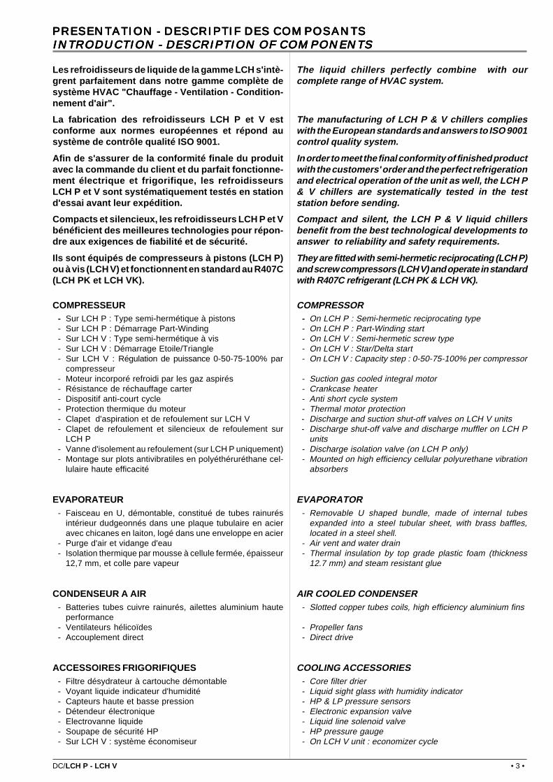
EVAPORATEUR- Faisceau en U, démontable, constitué de tubes rainurés
intérieur dudgeonnés dans une plaque tubulaire en acieravec chicanes en laiton, logé dans une enveloppe en acier
- Purge d'air et vidange d'eau- Isolation thermique par mousse à cellule fermée, épaisseur
12,7 mm, et colle pare vapeur
CONDENSEUR A AIR- Batteries tubes cuivre rainurés, ailettes aluminium haute
performance- Ventilateurs hélicoïdes- Accouplement direct
ACCESSOIRES FRIGORIFIQUES- Filtre désydrateur à cartouche démontable- Voyant liquide indicateur d'humidité- Capteurs haute et basse pression- Détendeur électronique- Electrovanne liquide- Soupape de sécurité HP- Sur LCH V : système économiseur
The liquid chillers perfectly combine with ourcomplete range of HVAC system.
The manufacturing of LCH P & V chillers complieswith the European standards and answers to ISO 9001control quality system.
In order to meet the final conformity of finished productwith the customers' order and the perfect refrigerationand electrical operation of the unit as well, the LCH P& V chillers are systematically tested in the teststation before sending.
Compact and silent, the LCH P & V liquid chillersbenefit from the best technological developments toanswer to reliability and safety requirements.
They are fitted with semi-hermetic reciprocating (LCH P)and screw compressors (LCH V) and operate in standardwith R407C refrigerant (LCH PK & LCH VK).
COMPRESSOR- On LCH P : Semi-hermetic reciprocating type- On LCH P : Part-Winding start- On LCH V : Semi-hermetic screw type- On LCH V : Star/Delta start- On LCH V : Capacity step : 0-50-75-100% per compressor
- Suction gas cooled integral motor- Crankcase heater- Anti short cycle system- Thermal motor protection- Discharge and suction shut-off valves on LCH V units- Discharge shut-off valve and discharge muffler on LCH P
units- Discharge isolation valve (on LCH P only)- Mounted on high efficiency cellular polyurethane vibration
absorbers
EVAPORATOR- Removable U shaped bundle, made of internal tubes
expanded into a steel tubular sheet, with brass baffles,located in a steel shell.
- Air vent and water drain- Thermal insulation by top grade plastic foam (thickness
12.7 mm) and steam resistant glue
AIR COOLED CONDENSER- Slotted copper tubes coils, high efficiency aluminium fins
- Propeller fans- Direct drive
COOLING ACCESSORIES- Core filter drier- Liquid sight glass with humidity indicator- HP & LP pressure sensors- Electronic expansion valve- Liquid line solenoid valve- HP pressure gauge- On LCH V unit : economizer cycle
PRESENTATION - DESCRIPTIF DES COMPOSANTSPRESENTATION - DESCRIPTIF DES COMPOSANTSPRESENTATION - DESCRIPTIF DES COMPOSANTSPRESENTATION - DESCRIPTIF DES COMPOSANTSPRESENTATION - DESCRIPTIF DES COMPOSANTSINTRODUCTION - DESCRIPTION OF COMPONENTSINTRODUCTION - DESCRIPTION OF COMPONENTSINTRODUCTION - DESCRIPTION OF COMPONENTSINTRODUCTION - DESCRIPTION OF COMPONENTSINTRODUCTION - DESCRIPTION OF COMPONENTS
• 4 • DC/LCH P - LCH V
ARMOIRE ELECTRIQUE- Etanchéité IP55, ventilée, avec portes sur char-
nières- Alimentation 400V/3/50 Hz + T- Tension de contrôle 230V/1/50 Hz (générée
par le transformateur de contrôle)- Alimentation séparée 230V/1/50 Hz (à prévoir
pour les résistances de carter)- Interrupteur de mise sous tension du circuit de
commande- Câblage conforme à la norme EN 60204-1
CHASSIS- Châssis rigide galvanisé à chaud par immersion- Peinture polyester - Couleur RAL 9002- Grille de protection des batteries verticales- Manutention par le châssis
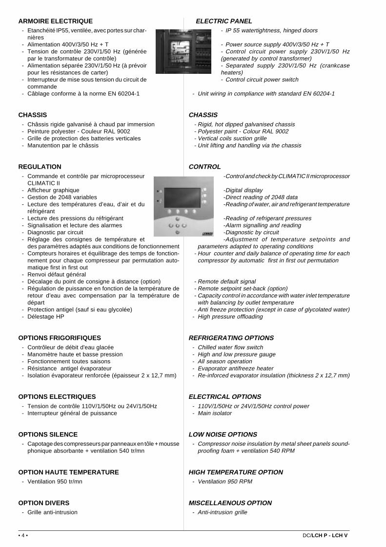
REGULATION- Commande et contrôle par microprocesseur
CLIMATIC II- Afficheur graphique- Gestion de 2048 variables- Lecture des températures d’eau, d’air et du
réfrigérant- Lecture des pressions du réfrigérant- Signalisation et lecture des alarmes- Diagnostic par circuit- Réglage des consignes de température et
des paramètres adaptés aux conditions de fonctionnement- Compteurs horaires et équilibrage des temps de fonction-
nement pour chaque compresseur par permutation auto-matique first in first out
- Renvoi défaut général- Décalage du point de consigne à distance (option)- Régulation de puissance en fonction de la température de
retour d’eau avec compensation par la température dedépart
- Protection antigel (sauf si eau glycolée)- Délestage HP
OPTIONS FRIGORIFIQUES- Contrôleur de débit d'eau glacée- Manomètre haute et basse pression- Fonctionnement toutes saisons- Résistance antigel évaporateur- Isolation évaporateur renforcée (épaisseur 2 x 12,7 mm)
OPTIONS ELECTRIQUES- Tension de contrôle 110V/1/50Hz ou 24V/1/50Hz- Interrupteur général de puissance
OPTIONS SILENCE- Capotage des compresseurs par panneaux en tôle + mousse
phonique absorbante + ventilation 540 tr/mn
OPTION HAUTE TEMPERATURE- Ventilation 950 tr/mn
OPTION DIVERS- Grille anti-intrusion
ELECTRIC PANEL- IP 55 watertightness, hinged doors
- Power source supply 400V/3/50 Hz + T- Control circuit power supply 230V/1/50 Hz(generated by control transformer)- Separated supply 230V/1/50 Hz (crankcaseheaters)- Control circuit power switch
- Unit wiring in compliance with standard EN 60204-1
CHASSIS- Rigid, hot dipped galvanised chassis- Polyester paint - Colour RAL 9002- Vertical coils suction grille- Unit lifting and handling via the chassis
CONTROL-Control and check by CLIMATIC II microprocessor
-Digital display-Direct reading of 2048 data-Reading of water, air and refrigerant temperature
-Reading of refrigerant pressures-Alarm signalling and reading-Diagnostic by circuit-Adjustment of temperature setpoints and
parameters adapted to operating conditions- Hour counter and daily balance of operating time for each
compressor by automatic first in first out permutation
- Remote default signal- Remote setpoint set-back (option)- Capacity control in accordance with water inlet temperature
with balancing by outlet temperature- Anti freeze protection (except in case of glycolated water)
- High pressure offloading
REFRIGERATING OPTIONS- Chilled water flow switch- High and low pressure gauge- All season operation- Evaporator antifreeze heater- Re-inforced evaporator insulation (thickness 2 x 12,7 mm)
ELECTRICAL OPTIONS- 110V/1/50Hz or 24V/1/50Hz control power- Main isolator
LOW NOISE OPTIONS- Compressor noise insulation by metal sheet panels sound-
proofing foam + ventilation 540 RPM
HIGH TEMPERATURE OPTION- Ventilation 950 RPM
MISCELLAENOUS OPTION- Anti-intrusion grille

DC/LCH P - LCH V • 5 •
L C H 41 2 P K
Fonctionnement au R407C (R22 si rien n'est mentionné)R407C operating (R22 if no other precision)
"P" Type de compresseur : P = Piston / V = VisCompressor type : P = Reciprocating / V = Screw type
Nombre de circuitsNumber of refrigerating circuits
Dixième de la puissance nominale en kWNominal capacity expressed in tens of kW
"H" Ventilation HélicoïdeAxial fans
"C" Chiller
"L" Large (> 300 kW)
EXEMPLE DE DESIGNATION DE GAMMEEXAMPLE OF UNIT RANGE DESIGNATIONS
CONFIGURATIONS DE CARROSSERIE - DIFFERENT POSSIBLE CASINGS
LCH P standard
Standard LCH P unitLCH V standard
Standard LCH V unit
LCH P avec option grille anti intrusionLCH P unit with anti intrusion grille
LCH V avec option grille anti intrusionLCH V unit with anti intrusion grille
LCH avec option isolation phoniqueLCH unit with sound insulation option
LCH avec options isolation phonique et grille anti intrusionLCH unit with noise insulation and anti intrusion grille options
• 6 • DC/LCH P - LCH V
MODELESMODELS
LCH322 PK
LCH412 PK
LCH462 PK
LCH662 PK
LCH532 PK
MODELESMODELS
LCH412 PK
LCH462 PK
LCH532 PK
LCH662 PK
LCH322 PK
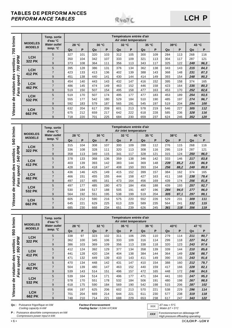
TABLES DE PERFORMANCESTABLES DE PERFORMANCESTABLES DE PERFORMANCESTABLES DE PERFORMANCESTABLES DE PERFORMANCESPERFORMANCE TABLESPERFORMANCE TABLESPERFORMANCE TABLESPERFORMANCE TABLESPERFORMANCE TABLES LCH PLCH PLCH PLCH PLCH P
Temp. sortied'eau °C
Water outlettemp. °C
Temp. sortied'eau °C
Water outlettemp. °C
MODELESMODELS
Temp. sortied'eau °C
Water outlettemp. °C
Fonctionnement en délestage HPHigh pressure offloading operating
XXX
Facteur d'encrassementFouling factor : 0,044 m2C/kW
LCH322 PK
LCH412 PK
LCH462 PK
LCH532 PK
LCH662 PK
Qo : Puissance frigorifique en kWCooling capacity in kW
P : Puissance absorbée compresseurs en kWCompressors power input in kW.
∆T eau = 5°CWater ∆T = 5°C
XXX
Vit
esse
de
rota
ito
n d
es v
enti
los
: 540
tr/m
inF
ans
spee
d :
540
RP
MV
ites
se d
e ro
tait
on
des
ven
tilo
s : 9
50 tr
/min
Fan
s sp
eed
; 95
0 R
PM
Vit
esse
de
rota
ito
n d
es v
enti
los
: 700
tr/m
inF
ans
spee
d :
700
RP
M
Température entrée d'airAir inlet temperature
28 °C 30 °C 32 °C 35 °C 39°C 43 °C
Qo P Qo P Qo P Qo P Qo P Qo P
5 327 101 320 103 312 105 300 109 284 113 268 1167 350 104 342 107 333 109 321 113 304 117 287 1219 373 108 364 111 356 113 343 117 325 122 249 96,3
5 395 128 386 131 376 134 362 138 343 143 215 84,37 423 133 413 136 402 139 388 143 368 148 231 87,39 451 138 440 141 430 144 414 149 393 154 248 90,3
5 454 140 443 143 432 147 416 152 395 158 374 1657 486 145 474 149 463 152 446 158 423 164 235 80,39 519 150 507 154 495 158 477 163 453 170 252 82,6
5 519 170 507 174 495 177 477 183 453 189 254 93,57 555 177 542 180 529 184 510 190 485 197 274 96,79 592 183 579 187 565 191 545 197 519 204 294 100
5 632 204 617 209 601 213 578 219 546 227 305 1127 675 212 659 217 642 222 618 228 585 236 328 1169 718 220 701 225 684 230 659 237 624 246 352 120
Température entrée d'airAir inlet temperature
28 °C 30 °C 32 °C 35 °C 38°C 40 °C
Qo P Qo P Qo P Qo P Qo P Qo P
5 315 104 308 107 300 109 288 112 276 115 268 1167 336 108 328 111 320 113 308 116 295 119 287 1219 358 113 349 115 341 117 328 121 315 124 250 96,0
5 378 133 368 136 359 138 346 142 333 146 217 83,87 403 139 393 142 383 144 369 148 239 85,2 233 86,99 428 145 418 147 408 150 393 154 256 88,2 249 89,9
5 436 146 425 149 415 152 399 157 384 162 374 1657 466 151 455 155 444 158 427 163 411 168 238 79,49 497 157 485 161 473 164 456 169 439 174 256 81,8
5 497 177 485 180 473 184 456 188 439 193 257 92,77 530 184 517 188 505 191 487 196 284 94,0 277 96,09 564 192 551 195 538 199 519 204 305 97,1 297 99,1
5 605 212 590 216 575 220 552 226 529 231 309 1117 645 221 629 225 613 229 589 235 564 241 332 1159 685 230 668 234 651 239 626 245 361 118 356 119
Température entrée d'airAir inlet temperature
28 °C 32 °C 35 °C 39 °C 43°C 47 °C
Qo P Qo P Qo P Qo P Qo P Qo P
5 338 97 323 102 311 106 295 110 279 114 211 90,77 362 100 345 106 333 109 316 114 299 118 227 94,29 386 103 369 109 356 113 338 118 320 123 243 97.6
5 412 124 392 129 377 134 358 139 339 144 210 85,67 441 128 420 134 404 138 384 144 364 149 226 88,79 471 132 449 139 433 143 411 149 390 155 243 91,6
5 470 134 448 142 431 147 410 154 388 160 212 79,77 504 139 480 147 463 152 440 159 417 166 228 82,19 539 143 514 151 496 157 472 165 448 172 246 84,5
5 539 164 514 171 496 177 471 184 441 193 247 95,37 578 170 551 178 532 184 506 191 480 198 267 98,59 618 175 590 184 569 190 542 198 515 206 287 102
5 656 197 625 206 602 213 570 221 538 229 296 1147 701 204 669 214 644 221 611 230 577 238 319 1189 748 210 714 221 688 229 653 238 617 247 343 122

DC/LCH P - LCH V • 7 •
TABLES DE PERFORMANCESTABLES DE PERFORMANCESTABLES DE PERFORMANCESTABLES DE PERFORMANCESTABLES DE PERFORMANCESPERFORMANCE TABLESPERFORMANCE TABLESPERFORMANCE TABLESPERFORMANCE TABLESPERFORMANCE TABLES LCH PLCH PLCH PLCH PLCH PR22
MODELESMODELS
Temp. sortied'eau °C
Water outlettemp. °C
MODELESMODELS
Temp. sortied'eau °C
Water outlettemp. °C
MODELESMODELS
Temp. sortied'eau °C
Water outlettemp. °C
Fonctionnement en délestage HPHigh pressure offloading operating
XXX
∆T eau = 5°CWater ∆T = 5°CXXX
Qo : Puissance frigorifique en kWCooling capacity in kW.
P : Puissance absorbée compresseurs en kWCompressors power input in kW.
Facteur d'encrassementFouling factor : 0,044 m2C/kW
Vit
esse
de
rota
ito
n d
es v
enti
los
: 540
tr/m
inF
ans
spee
d :
540
RP
MV
ites
se d
e ro
tait
on
des
ven
tilo
s : 9
50 tr
/min
Fan
s sp
eed
; 95
0 R
PM
Vit
esse
de
rota
ito
n d
es v
enti
los
: 700
tr/m
inF
ans
spee
d :
700
RP
M
LCH412 P
LCH462 P
LCH532 P
LCH662 P
LCH322 P
LCH322 P
LCH412 P
LCH462 P
LCH532 P
LCH662 P
LCH322 P
LCH412 P
LCH462 P
LCH532 P
LCH662 P
Température entrée d'airAir inlet temperature
28 °C 30 °C 32 °C 35 °C 38°C 40 °C
Qo P Qo P Qo P Qo P Qo P Qo P
5 313 104 306 107 300 109 290 113 280 116 273 1197 333 108 326 111 319 113 309 117 298 121 291 1249 355 112 347 115 340 118 329 122 317 126 310 129
5 393 138 384 142 376 145 363 150 351 155 343 1587 417 144 408 147 399 151 386 156 373 161 244 919 442 150 433 154 423 157 409 163 266 92 260 94
5 452 151 442 155 433 158 419 164 405 169 395 1737 481 157 471 160 461 164 446 170 431 176 421 1809 511 162 500 166 489 170 473 177 458 183 447 187
5 517 183 506 188 495 192 479 198 463 205 452 2107 549 191 537 195 526 200 509 207 492 214 289 999 582 199 570 203 558 208 540 216 315 100 308 103
5 603 213 590 217 577 222 557 229 538 236 525 2417 641 221 628 226 614 231 593 239 573 246 559 2519 681 230 666 235 652 240 630 248 608 256 356 119
Température entrée d'airAir inlet temperature
28 °C 32 °C 35 °C 39 °C 43°C 47 °C
Qo P Qo P Qo P Qo P Qo P Qo P
5 333 96 320 102 309 106 296 111 283 115 270 1207 356 99 342 105 331 109 317 114 303 120 288 1259 380 102 365 108 353 113 338 118 323 124 308 1295 425 127 407 133 394 138 376 145 359 151 343 1587 453 131 434 138 420 143 402 150 384 157 238 939 482 135 462 142 447 148 428 155 409 163 254 965 485 139 464 146 449 152 430 160 411 167 392 1747 517 143 496 151 480 157 459 165 439 173 419 1819 551 146 528 155 512 162 490 170 468 179 447 1875 557 168 535 176 518 183 495 192 474 200 453 2107 594 173 570 183 552 189 529 199 506 208 280 1039 632 179 607 189 588 196 563 206 539 216 299 1065 647 195 620 206 601 213 574 223 548 233 522 2427 691 202 663 213 642 221 613 231 586 241 558 2519 737 208 706 220 684 228 654 240 625 250 344 124
Température entrée d'airAir inlet temperature
28 °C 30 °C 32 °C 35 °C 39°C 43 °C
Qo P Qo P Qo P Qo P Qo P Qo P
5 324 100 317 103 310 105 300 109 287 114 274 1197 345 104 338 106 331 109 320 113 306 118 292 1239 368 107 360 110 353 113 341 117 327 123 312 128
5 410 132 401 135 392 139 379 144 362 150 346 1577 436 137 426 141 417 144 404 149 386 156 243 919 463 142 453 146 443 149 429 155 410 162 259 94
5 469 145 459 148 449 152 435 158 416 165 397 1737 500 149 489 153 479 157 463 163 443 171 423 1799 531 154 520 158 509 163 493 169 472 177 451 186
5 538 175 527 179 515 184 499 190 477 199 456 2087 573 182 561 186 549 191 531 198 509 207 486 2179 608 188 596 193 583 198 565 205 547 213 306 103
5 626 204 613 209 600 214 580 221 554 231 528 2407 667 211 653 216 639 222 618 230 591 240 563 2499 710 219 695 224 680 230 658 238 629 249 600 259
• 8 • DC/LCH P - LCH V
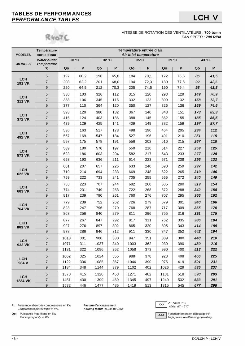
TABLES DE PERFORMANCESTABLES DE PERFORMANCESTABLES DE PERFORMANCESTABLES DE PERFORMANCESTABLES DE PERFORMANCESPERFORMANCE TABLESPERFORMANCE TABLESPERFORMANCE TABLESPERFORMANCE TABLESPERFORMANCE TABLES
VITESSE DE ROTATION DES VENTILATEURS : 700 tr/mnFAN SPEED : 700 RPM
LCH VLCH VLCH VLCH VLCH V
Qo : Puissance frigorifique en kWCooling capacity in kW.
P : Puissance absorbée compresseurs en kWCompressors power input in kW.
Facteur d'encrassementFouling factor : 0,044 m2C/kW
∆T eau = 5°CWater ∆T = 5°C
XXX
Fonctionnement en délestage HPHigh pressure offloading operating
XXX
LCH191 VK
LCH311 VK
LCH372 VK
LCH492 VK
LCH573 VK
LCH622 VK
LCH683 VK
LCH764 VK
LCH803 VK
LCH933 VK
LCH984 V
LCH1234 VK
Température Température entrée d'airMODELES sortie d'eau Air inlet temperature
Water outlet 28 °C 32 °C 35°C 39 °C 43 °CMODELS Temperature
°C Qo P Qo P Qo P Qo P Qo P
5 197 60,2 190 65,8 184 70,1 172 75,6 86 41,5
7 208 62,2 201 68,0 194 72,3 180 77,5 92 42,69 220 64,5 212 70,3 205 74,5 190 79,4 98 43,8
5 338 103 326 112 315 120 293 129 149 70,97 358 106 345 116 332 123 309 132 158 72,79 377 110 364 120 350 127 326 136 169 74,6
5 393 120 380 132 367 140 343 151 173 83,37 416 124 403 136 388 145 362 155 185 85,59 439 129 425 141 409 149 382 159 197 87,7
5 536 163 517 178 498 190 464 205 234 1127 567 169 547 184 527 196 491 210 251 1159 597 175 578 191 556 202 516 215 267 118
5 589 180 570 197 550 210 514 227 259 1257 623 186 603 204 582 217 543 233 277 1289 658 193 636 211 614 223 571 238 296 132
5 681 207 657 226 633 240 590 259 297 1427 719 214 694 233 669 248 622 265 319 1469 759 222 733 241 705 255 655 272 340 149
5 733 223 707 244 682 260 636 280 319 1547 774 231 749 253 722 268 672 288 342 1589 817 239 790 261 760 276 707 295 366 162
5 779 239 752 262 726 279 679 301 340 1667 823 247 796 270 768 287 717 309 365 1709 868 256 840 279 811 296 755 316 391 175
5 877 267 847 292 817 311 762 335 386 1847 927 276 897 302 865 320 805 343 414 1899 978 286 946 312 911 330 847 352 442 194
5 1013 301 980 330 947 351 889 380 448 2107 1071 311 1037 340 1003 362 939 390 480 2169 1131 322 1096 352 1058 373 990 400 513 222
5 1062 325 1024 355 988 378 923 408 466 2257 1122 336 1085 367 1046 390 975 419 501 2319 1184 348 1144 379 1102 402 1026 429 535 237
5 1370 415 1320 453 1271 482 1181 518 590 2837 1451 430 1399 469 1345 497 1249 532 633 2919 1532 446 1477 485 1419 513 1315 545 677 298

DC/LCH P - LCH V • 9 •
TABLES DE PERFORMANCESTABLES DE PERFORMANCESTABLES DE PERFORMANCESTABLES DE PERFORMANCESTABLES DE PERFORMANCESPERFORMANCE TABLESPERFORMANCE TABLESPERFORMANCE TABLESPERFORMANCE TABLESPERFORMANCE TABLES
VITESSE DE ROTATION DES VENTILATEURS : 540 tr/mnFAN SPEED : 540 RPM
LCH VLCH VLCH VLCH VLCH V
Qo : Puissance frigorifique en kWCooling capacity in kW.
P : Puissance absorbée compresseurs en kWCompressors power input in kW.
Facteur d'encrassementFouling factor : 0,044 m2C/kW
∆T eau = 5°CWater ∆T = 5°C
XXX
Fonctionnement en délestage HPHigh pressure offloading operating
XXX
LCH191 VK
LCH311 VK
LCH372 VK
LCH492 VK
LCH573 VK
LCH622 VK
LCH683 VK
LCH764 VK
LCH803 VK
LCH933 VK
LCH984 VK
LCH1234 VK
Température Température entrée d'airMODELES sortie d'eau Air inlet temperature
Water outlet 25 °C 28 °C 32°C 35 °C 40 °CMODELS Temperature
°C Qo P Qo P Qo P Qo P Qo P
5 196 60,9 191 65,2 182 70,8 173 74,8 87 40,87 207 63,2 201 67,7 193 73,3 183 77,1 93 42,09 218 65,8 212 70,3 201 75,7 191 79,2 100 43,2
5 337 104 328 112 311 121 296 128 151 69,77 355 108 345 116 329 125 311 132 162 71,79 374 113 364 120 344 129 327 135 172 73,7
5 392 122 382 130 364 142 347 150 176 81,97 414 126 404 135 384 147 365 154 207 91,39 436 132 425 141 404 152 383 159 218 93,7
5 534 165 519 177 494 192 470 203 239 1117 563 172 548 184 521 199 494 209 255 1149 593 179 576 191 547 205 518 215 272 117
5 586 182 572 195 546 212 519 225 264 1237 619 189 604 203 575 220 547 231 282 1269 653 197 636 211 605 227 574 238 300 130
5 678 209 659 224 627 243 595 257 303 1407 715 218 695 233 660 252 626 264 325 1449 754 227 732 242 693 260 657 271 345 148
5 729 226 711 242 677 263 644 278 326 1517 771 235 750 251 713 272 677 286 349 1569 812 245 790 261 749 281 710 294 372 160
5 776 242 756 259 721 282 686 298 347 1637 820 251 799 269 760 291 723 307 372 1689 864 261 840 279 800 301 759 315 396 172
5 873 270 850 289 810 314 770 332 394 1817 922 281 898 301 854 325 811 342 421 1869 971 292 945 312 897 336 849 351 449 192
5 1011 304 986 325 942 354 900 375 457 2077 1067 315 1041 337 994 366 948 386 488 2129 1125 328 1097 350 1046 379 997 397 520 218
5 1057 328 1029 352 980 382 933 404 475 2217 1117 341 1087 365 1034 396 982 416 509 2279 1176 355 1144 379 1087 409 1031 428 542 234
5 1363 421 1326 450 1258 488 1194 514 602 2787 1441 438 1400 468 1328 505 1257 529 644 2869 1520 456 1475 487 1395 522 1318 544 688 295

• 10 • DC/LCH P - LCH V
TABLES DE PERFORMANCESTABLES DE PERFORMANCESTABLES DE PERFORMANCESTABLES DE PERFORMANCESTABLES DE PERFORMANCESPERFORMANCE TABLESPERFORMANCE TABLESPERFORMANCE TABLESPERFORMANCE TABLESPERFORMANCE TABLES
VITESSE DE ROTATION DES VENTILATEURS : 950 tr/mnFAN SPEED : 950 RPM
LCH VLCH VLCH VLCH VLCH V
∆T eau = 6°CWater ∆T = 6°C
XXX
Fonctionnement en délestage HPHigh pressure offloading operating
XXX∆T eau = 5°CWater ∆T = 5°C
XXXQo : Puissance frigorifique en kWCooling capacity in kW.
P : Puissance absorbée compresseurs en kWCompressors power input in kW.
Facteur d'encrassementFouling factor : 0,044 m2C/kW
LCH191 VK
LCH311 VK
LCH372 VK
LCH492 VK
LCH573 VK
LCH622 VK
LCH683 VK
LCH764 VK
LCH803 VK
LCH933 VK
LCH984 VK
LCH1234 VK
Température Température entrée d'airMODELES sortie d'eau Air inlet temperature
Water outlet 28 °C 32 °C 35°C 39 °C 43 °C 47 °CMODELS Temperature
°C Qo P Qo P Qo P Qo P Qo P Qo P
5 201 56,0 196 61,4 190 65,6 182 71,3 167 76,8 82,0 43,07 212 57,8 207 63,3 201 67,6 191 73,3 177 78,5 88,0 44,09 224 59,6 219 65,3 213 69,7 202 75,3 187 80,3 94,0 45,0
5 345 95,7 336 105 327 112 310 122 287 131 142 73,37 365 99,0 355 108 347 115 329 125 304 134 152 75,09 386 102 376 111 366 119 348 128 320 137 163 76,7
5 402 112 391 123 381 131 362 143 336 154 165 86,27 425 115 414 126 404 135 384 147 355 157 177 88,29 448 119 437 131 427 139 406 151 375 161 189 90,2
5 548 152 532 166 518 178 492 193 455 208 224 1167 579 157 563 171 549 183 521 199 482 213 241 1199 611 162 595 177 580 189 551 204 362 152 257 122
5 602 168 585 184 570 197 542 214 504 230 248 1297 636 173 619 190 604 203 575 220 532 236 266 1329 671 179 655 196 639 209 608 226 562 241 285 135
5 696 192 677 210 658 225 625 244 576 263 285 1477 736 198 716 217 697 232 662 251 611 269 306 1509 777 205 757 224 737 239 699 258 353 145 327 154
5 749 208 728 228 708 243 673 265 623 285 306 1597 792 214 771 235 751 251 714 272 659 291 329 1639 836 221 814 242 794 258 754 279 549 232 352 167
5 795 223 773 244 752 261 716 284 664 306 326 1727 840 230 818 251 798 269 760 292 704 313 350 1769 887 237 865 259 844 277 803 300 743 320 375 180
5 897 248 871 272 849 291 807 316 747 340 370 1907 947 256 923 280 900 299 856 325 791 348 397 1959 1000 264 975 289 950 309 903 333 459 188 425 199
5 1035 281 1005 308 980 330 934 359 869 387 429 2187 1095 290 1065 317 1040 339 991 369 921 396 461 2239 1155 299 1125 327 1099 349 1048 378 972 405 493 228
5 1085 302 1054 331 1026 354 976 385 904 415 447 2337 1146 311 1117 341 1088 365 1034 396 957 424 480 2389 1210 321 1179 352 1150 376 1093 406 1009 433 514 243
5 1403 386 1361 422 1323 451 1254 490 1156 526 564 2937 1485 398 1443 436 1405 465 1331 503 1225 538 606 3009 1569 412 1527 450 1486 480 1407 517 703 289 650 307
DC/LCH P - LCH V • 11 •
LCH191 V
LCH311 V
LCH372 V
LCH492 V
LCH573 V
LCH622 V
LCH683 V
LCH764 V
LCH803 V
LCH933 V
LCH984 V
LCH1234 V
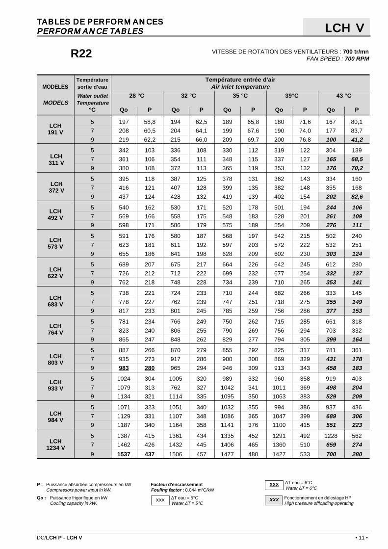
TABLES DE PERFORMANCESTABLES DE PERFORMANCESTABLES DE PERFORMANCESTABLES DE PERFORMANCESTABLES DE PERFORMANCESPERFORMANCE TABLESPERFORMANCE TABLESPERFORMANCE TABLESPERFORMANCE TABLESPERFORMANCE TABLES
VITESSE DE ROTATION DES VENTILATEURS : 700 tr/mnFAN SPEED : 700 RPM
LCH VLCH VLCH VLCH VLCH V
∆T eau = 6°CWater ∆T = 6°C
XXX
Fonctionnement en délestage HPHigh pressure offloading operating
XXX∆T eau = 5°CWater ∆T = 5°C
XXXQo : Puissance frigorifique en kWCooling capacity in kW.
P : Puissance absorbée compresseurs en kWCompressors power input in kW.
Facteur d'encrassementFouling factor : 0,044 m2C/kW
Température Température entrée d'airMODELES sortie d'eau Air inlet temperature
Water outlet 28 °C 32 °C 35 °C 39°C 43 °CMODELS Temperature
°C Qo P Qo P Qo P Qo P Qo P
5 197 58,8 194 62,5 189 65,8 180 71,6 167 80,1
7 208 60,5 204 64,1 199 67,6 190 74,0 177 83,7
9 219 62,2 215 66,0 209 69,7 200 76,8 100 41,2
5 342 103 336 108 330 112 319 122 304 139
7 361 106 354 111 348 115 337 127 165 68,59 380 108 372 113 365 119 353 132 176 70,2
5 395 118 387 125 378 131 362 143 334 160
7 416 121 407 128 399 135 382 148 355 168
9 437 124 428 132 419 139 402 154 202 82,6
5 540 162 530 171 520 178 501 194 244 1067 569 166 558 175 548 183 528 201 261 1099 598 171 586 179 575 189 554 209 276 111
5 591 176 580 187 568 197 542 215 502 240
7 623 181 611 192 597 203 572 222 532 251
9 655 186 641 198 628 209 602 230 303 124
5 689 207 675 217 664 226 642 245 612 280
7 726 212 712 222 699 232 677 254 332 1379 762 218 748 228 734 239 710 265 353 141
5 738 221 724 233 710 244 682 266 333 145
7 778 227 762 239 747 251 718 275 355 1499 817 233 801 245 785 259 756 286 377 153
5 781 234 766 249 750 262 715 285 661 318
7 823 240 806 255 790 269 756 294 703 332
9 865 247 848 262 829 277 794 305 399 164
5 887 266 870 279 855 292 825 317 781 361
7 935 273 917 286 900 300 869 329 431 1789 983 280 965 294 946 309 913 343 458 183
5 1024 304 1005 320 989 332 960 358 919 403
7 1079 313 762 327 1042 341 1011 369 498 2049 1134 321 1114 335 1095 350 1063 383 529 209
5 1071 323 1051 340 1032 355 994 386 937 436
7 1129 331 1107 348 1086 365 1047 399 689 3069 1187 340 1164 358 1141 376 1100 415 551 223
5 1387 415 1361 434 1335 452 1291 492 1228 562
7 1462 426 1432 445 1406 465 1360 510 659 274
9 1537 437 1506 457 1477 480 1427 533 700 280
R22
• 12 • DC/LCH P - LCH V
LCH191 V
LCH311 V
LCH372 V
LCH492 V
LCH573 V
LCH622 V
LCH683 V
LCH764 V
LCH803 V
LCH933 V
LCH984 V
LCH1234 V
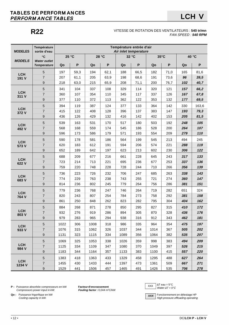
TABLES DE PERFORMANCESTABLES DE PERFORMANCESTABLES DE PERFORMANCESTABLES DE PERFORMANCESTABLES DE PERFORMANCESPERFORMANCE TABLESPERFORMANCE TABLESPERFORMANCE TABLESPERFORMANCE TABLESPERFORMANCE TABLES
VITESSE DE ROTATION DES VENTILATEURS : 540 tr/mnFAN SPEED : 540 RPM
LCH VLCH VLCH VLCH VLCH V
Fonctionnement en délestage HPHigh pressure offloading operating
XXX
∆T eau = 5°CWater ∆T = 5°C
XXX
Qo : Puissance frigorifique en kWCooling capacity in kW.
P : Puissance absorbée compresseurs en kWCompressors power input in kW.
Facteur d'encrassementFouling factor : 0,044 m2C/kW
Température Température entrée d'airMODELES sortie d'eau Air inlet temperature
°C 25 °C 28 °C 32 °C 35°C 40 °CMODELS Water outlet
Temperature Qo P Qo P Qo P Qo P Qo P
5 197 59,3 194 62,1 188 66,5 182 71,0 165 81,6
7 207 61,1 205 63,9 198 68,6 191 73,6 96 39,59 218 63,0 215 65,9 208 71,1 200 76,7 102 40,7
5 341 104 337 108 329 114 320 121 157 66,27 360 107 354 110 345 117 337 126 167 67,89 377 110 372 113 362 122 353 132 177 69,5
5 394 119 387 124 377 133 364 142 330 163,6
7 415 122 408 128 396 137 383 147 193 79,39 436 126 429 132 416 142 402 153 205 81,5
5 539 163 531 170 517 180 503 192 248 1057 568 168 559 174 545 186 528 200 264 1079 596 173 586 179 571 193 554 209 279 110
5 590 178 581 186 564 199 545 213 494 245
7 620 183 612 191 594 206 574 221 288 1199 652 189 642 197 623 213 602 230 306 122
5 688 209 677 216 661 228 645 243 317 1337 723 214 713 221 695 236 677 253 337 1369 759 220 748 228 728 244 710 266 356 139
5 736 223 726 232 706 247 685 263 338 1437 774 229 763 238 743 255 721 274 360 1479 814 236 802 245 779 264 756 286 381 151
5 779 236 768 247 746 264 719 282 651 324
7 820 243 807 254 784 273 758 292 381 1589 861 250 848 262 823 282 795 304 404 162
5 884 268 871 278 850 295 827 315 410 1727 932 276 919 286 894 305 870 328 436 1769 979 283 965 294 938 316 912 343 462 181
5 1022 306 1008 318 986 335 964 354 475 1977 1076 315 1062 326 1037 344 1014 367 505 2029 1131 323 1115 334 1089 356 1064 382 535 207
5 1069 325 1053 338 1026 359 998 383 494 2097 1125 334 1109 347 1080 370 1049 397 526 2159 1183 344 1164 357 1133 383 1100 415 557 220
5 1383 418 1363 433 1329 458 1295 488 627 2647 1455 430 1433 444 1397 473 1361 509 667 2719 1529 441 1506 457 1465 491 1426 535 706 278
R22

DC/LCH P - LCH V • 13 •
LCH191 V
LCH311 V
LCH372 V
LCH492 V
LCH573 V
LCH622 V
LCH683 V
LCH764 V
LCH803 V
LCH933 V
LCH984 V
LCH1234 V
TABLES DE PERFORMANCESTABLES DE PERFORMANCESTABLES DE PERFORMANCESTABLES DE PERFORMANCESTABLES DE PERFORMANCESPERFORMANCE TABLESPERFORMANCE TABLESPERFORMANCE TABLESPERFORMANCE TABLESPERFORMANCE TABLES
VITESSE DE ROTATION DES VENTILATEURS : 950 tr/mnFAN SPEED : 950 RPM
LCH VLCH VLCH VLCH VLCH V
∆T eau = 6°CWater ∆T = 6°C
XXX
Fonctionnement en délestage HPHigh pressure offloading operating
XXX∆T eau = 5°CWater ∆T = 5°C
XXXQo : Puissance frigorifique en kWCooling capacity in kW.
P : Puissance absorbée compresseurs en kWCompressors power input in kW.
Facteur d'encrassementFouling factor : 0,044 m2C/kW
Température Température entrée d'airMODELES sortie d'eau Air inlet temperature
Water outlet 28 °C 32 °C 35°C 39 °C 43 °C 47 °CMODELS Temperature
°C Qo P Qo P Qo P Qo P Qo P Qo P
5 200 55,7 197 59,5 194 62,3 188 66,7 178 73,0 164 82,1
7 211 57,3 207 61,1 205 63,8 198 68,4 189 75,3 92,0 41,69 222 59,1 218 62,7 215 65,5 209 70,3 199 77,8 97,0 42,7
5 348 98,4 341 104 337 108 329 114 318 124 151 69,07 366 101 360 106 354 110 347 117 334 128 161 70,79 385 104 378 109 373 113 364 120 352 133 172 72,5
5 400 111 393 119 387 125 376 133 358 146 328 164
7 421 115 415 122 408 128 397 137 378 151 184 83,49 443 118 436 125 429 131 418 141 399 156 196 85,6
5 549 154 539 164 531 170 517 181 496 197 238 1107 578 159 568 168 560 174 546 185 525 204 253 1129 607 163 597 172 589 178 573 190 552 212 268 115
5 601 167 589 178 580 187 563 200 536 219 492 247
7 631 172 620 183 612 191 594 205 568 226 276 1259 664 177 653 188 644 196 626 211 598 233 294 128
5 700 197 686 209 677 216 661 228 639 249 304 1387 737 203 724 214 714 221 696 234 673 258 323 1429 774 209 761 218 750 226 733 241 707 268 343 145
5 750 210 736 223 725 232 706 247 675 271 323 1507 790 216 776 229 765 238 744 254 714 279 344 1549 831 222 816 234 804 244 782 261 751 290 366 158
5 793 221 778 237 767 248 745 266 706 290 647 326
7 835 228 820 243 807 254 785 272 748 299 364 1669 878 235 862 249 850 260 826 280 790 309 387 170
5 900 253 883 268 871 278 850 295 820 323 393 1797 949 261 933 275 920 285 897 303 865 334 419 1849 999 269 982 282 968 292 944 312 910 346 444 189
5 1040 289 1020 308 1005 319 983 336 954 364 454 2067 1095 298 1076 316 1060 326 1037 344 1005 376 484 2109 1151 307 1132 323 1117 334 1091 353 1057 389 515 216
5 1088 307 1068 326 1053 339 1026 360 986 393 473 2197 1145 316 1125 334 1109 347 1081 369 1041 405 504 2249 1205 325 1185 342 1167 355 1137 379 1095 420 536 230
5 1409 397 1383 418 1363 433 1330 457 1284 500 601 2767 1484 408 1458 428 1437 442 1401 469 1353 518 640 2829 1561 420 1533 439 1510 453 1473 483 1422 539 681 289
R22
• 14 • DC/LCH P - LCH V
CARACTERISTIQUES TECHNIQUESCARACTERISTIQUES TECHNIQUESCARACTERISTIQUES TECHNIQUESCARACTERISTIQUES TECHNIQUESCARACTERISTIQUES TECHNIQUESTECHNICAL DATATECHNICAL DATATECHNICAL DATATECHNICAL DATATECHNICAL DATA
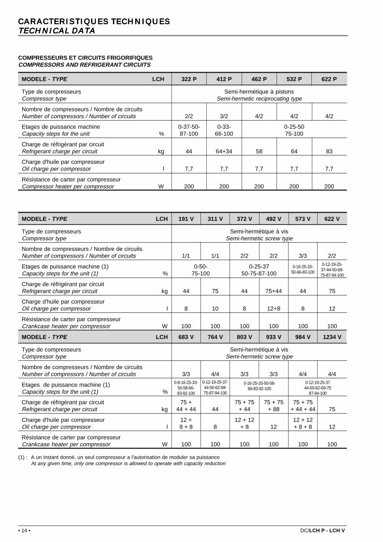
COMPRESSEURS ET CIRCUITS FRIGORIFIQUESCOMPRESSORS AND REFRIGERANT CIRCUITS
(1) : A un instant donné, un seul compresseur a l'autorisation de moduler sa puissanceAt any given time, only one compressor is allowed to operate with capacity reduction
0-16-25-33-50-66-83-100
0-12-19-25-37-44-50-69-75-87-94-100
0-8-16-25-33-50-58-66-83-92-100
0-12-19-25-37-44-50-62-69-75-87-94-100
0-16-25-33-50-58-66-83-92-100
0-12-19-25-3744-50-62-69-75
87-94-100
MODELE - TYPE LCH 191 V 311 V 372 V 492 V 573 V 622 V
Type de compresseurs Semi-hermétique à visCompressor type Semi-hermetic screw type
Nombre de compresseurs / Nombre de circuitsNumber of compressors / Number of circuits 1/1 1/1 2/2 2/2 3/3 2/2
Etages de puissance machine (1) 0-50- 0-25-37Capacity steps for the unit (1) % 75-100 50-75-87-100
Charge de réfrigérant par circuitRefrigerant charge per circuit kg 44 75 44 75+44 44 75
Charge d'huile par compresseurOil charge per compressor l 8 10 8 12+8 8 12
Résistance de carter par compresseurCrankcase heater per compressor W 100 100 100 100 100 100
MODELE - TYPE LCH 683 V 764 V 803 V 933 V 984 V 1234 V
Type de compresseurs Semi-hermétique à visCompressor type Semi-hermetic screw type
Nombre de compresseurs / Nombre de circuitsNumber of compressors / Number of circuits 3/3 4/4 3/3 3/3 4/4 4/4
Etages de puissance machine (1)Capacity steps for the unit (1) %
Charge de réfrigérant par circuit 75 + 75 + 75 75 + 75 75 + 75Refrigerant charge per circuit kg 44 + 44 44 + 44 + 88 + 44 + 44 75
Charge d'huile par compresseur 12 + 12 + 12 12 + 12Oil charge per compressor l 8 + 8 8 + 8 12 + 8 + 8 12
Résistance de carter par compresseurCrankcase heater per compressor W 100 100 100 100 100 100
MODELE - TYPE LCH 322 P 412 P 462 P 532 P 622 P
Type de compresseurs Semi-hermétique à pistonsCompressor type Semi-hermetic reciprocating type
Nombre de compresseurs / Nombre de circuitsNumber of compressors / Number of circuits 2/2 3/2 4/2 4/2 4/2
Etages de puissance machine 0-37-50- 0-33- 0-25-50Capacity steps for the unit % 87-100 66-100 75-100
Charge de réfrigérant par circuitRefrigerant charge per circuit kg 44 64+34 58 64 83
Charge d'huile par compresseurOil charge per compressor l 7,7 7,7 7,7 7,7 7,7
Résistance de carter par compresseurCompressor heater per compressor W 200 200 200 200 200
DC/LCH P - LCH V • 15 •
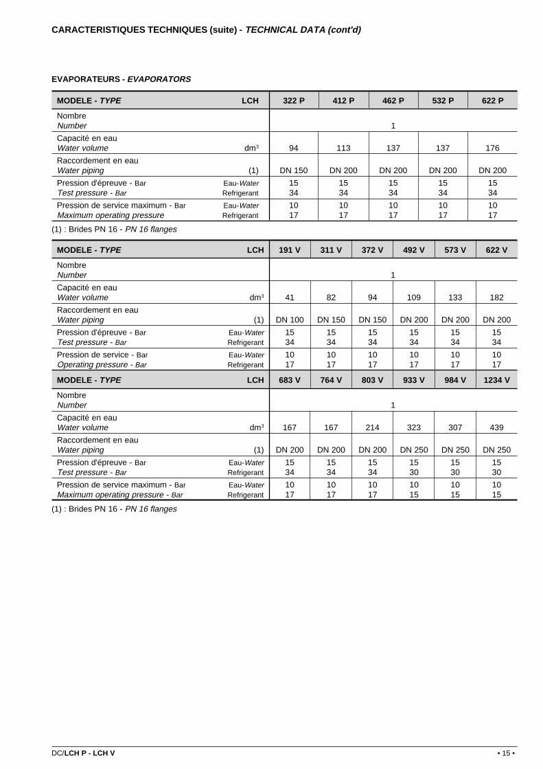
EVAPORATEURS - EVAPORATORS
(1) : Brides PN 16 - PN 16 flanges
CARACTERISTIQUES TECHNIQUES (suite) - TECHNICAL DATA (cont'd)
(1) : Brides PN 16 - PN 16 flanges
MODELE - TYPE LCH 322 P 412 P 462 P 532 P 622 P
NombreNumber 1
Capacité en eauWater volume dm3 94 113 137 137 176
Raccordement en eauWater piping (1) DN 150 DN 200 DN 200 DN 200 DN 200
Pression d'épreuve - Bar Eau-Water 15 15 15 15 15Test pressure - Bar Refrigerant 34 34 34 34 34
Pression de service maximum - Bar Eau-Water 10 10 10 10 10Maximum operating pressure Refrigerant 17 17 17 17 17
MODELE - TYPE LCH 191 V 311 V 372 V 492 V 573 V 622 V
NombreNumber 1
Capacité en eauWater volume dm3 41 82 94 109 133 182
Raccordement en eauWater piping (1) DN 100 DN 150 DN 150 DN 200 DN 200 DN 200
Pression d'épreuve - Bar Eau-Water 15 15 15 15 15 15Test pressure - Bar Refrigerant 34 34 34 34 34 34
Pression de service - Bar Eau-Water 10 10 10 10 10 10Operating pressure - Bar Refrigerant 17 17 17 17 17 17
MODELE - TYPE LCH 683 V 764 V 803 V 933 V 984 V 1234 V
NombreNumber 1
Capacité en eauWater volume dm3 167 167 214 323 307 439
Raccordement en eauWater piping (1) DN 200 DN 200 DN 200 DN 250 DN 250 DN 250
Pression d'épreuve - Bar Eau-Water 15 15 15 15 15 15Test pressure - Bar Refrigerant 34 34 34 30 30 30
Pression de service maximum - Bar Eau-Water 10 10 10 10 10 10Maximum operating pressure - Bar Refrigerant 17 17 17 15 15 15

• 16 • DC/LCH P - LCH V
CONDENSEURS - CONDENSERS
CARACTERISTIQUES TECHNIQUES (suite) - TECHNICAL DATA (cont'd)70
0 tr
/mn
700
RPM
540
tr/m
n54
0 R
PM95
0 tr
/mn
950
RPM
700
tr/m
n70
0 R
PM54
0 tr
/mn
540
RPM
950
tr/m
n95
0 R
PM70
0 tr
/mn
700
RPM
540
tr/m
n54
0 R
PM95
0 tr
/mn
950
RPM
MODELE - TYPE LCH 322 P 412 P 462 P 532 P 622 P
Type de de ventilation Hélicoïde - Accouplement directVentilation type Axial - Direct coupling
Nombre de ventilateurs - Fan number 6 6 8 8 10
Débit d'air - Air flow rate m3/h 123 000 127 600 163 200 169 600 213 000
Puiss. absorbée totale - Total input kW 10,2 10,2 13,6 13,6 17,0
Int. maxi par ventilateur - Each fan full load current A 5,5 5,5 5,5 5,5 5,5
Débit d'air - Air flow rate m3/h 94 800 98 400 125 800 130 800 164 400
Puiss. absorbée totale - Total input kW 6 6 8 8 10
Int. maxi par ventilateur - Each fan full load current A 2 2 2 2 2
Débit d'air - Air flow rate m3/h 166 400 172 600 220 800 229 400 288 200
Puiss. absorbée totale - Total input kW 19,8 19,8 26,4 26,4 33,0
Int. maxi par ventilateur - Each fan full load current A 6,2 6,2 6,2 6,2 6,2
MODELE - TYPE LCH 191 V 311 V 372 V 492 V 573 V 622 V
Type de de ventilation Hélicoïde - Accouplement directVentilation type Axial - Direct coupling
Nombre de ventilateurs - Fan number 3 5 6 8 9 10
Débit d'air - Air flow rate m3/h 61 500 102 500 123 000 164 000 184 500 205 000
Puiss. absorbée totale - Total input kW 5,1 8,5 10,2 13,6 15,3 17,0
Int. maxi par ventilateur - Each fan full load current A 5,5 5,5 5,5 5,5 5,5 5,5
Débit d'air - Air flow rate m3/h 47 400 79 100 94 800 126 500 142 200 158 200
Puiss. absorbée totale - Total input kW 3,0 5,0 6,0 8,0 9,0 10,0
Int. maxi par ventilateur - Each fan full load current A 2,0 2,0 2,0 2,0 2,0 2,0
Débit d'air - Air flow rate m3/h 83 200 138 700 166 400 221 900 249 600 277 400
Puiss. absorbée totale - Total input kW 9,9 16,5 19,8 26,4 29,7 33,0
Int. maxi par ventilateur - Each fan full load current A 6,2 6,2 6,2 6,2 6,2 6,2
MODELE - TYPE LCH V 683 V 764 V 803 V 933 V 984 V 1234 V
Type de de ventilation Hélicoïde - Accouplement directVentilation type Axial - Direct coupling
Nombre de ventilateurs - Fan number 11 12 13 16 16 20
Débit d'air - Air flow rate m3/h 225 500 246 000 266 500 328 000 328 000 410 000
Puiss. absorbée totale - Total input kW 18,7 20,4 22,1 27,2 27,2 34,0
Int. maxi par ventilateur - Each fan full load current A 5,5 5,5 5,5 5,5 5,5 5,5
Débit d'air - Air flow rate m3/h 173 800 189 600 205 600 253 000 253 000 316 400
Puiss. absorbée totale - Total input kW 11,0 12,0 13,0 16,0 16,0 20,0
Int. maxi par ventilateur - Each fan full load current A 2,0 2,0 2,0 2,0 2,0 2,0
Débit d'air - Air flow rate m3/h 305 100 332 800 360 600 443 800 443 800 554 800
Puiss. absorbée totale - Total input kW 36,3 39,6 42,9 52,8 52,8 66,0
Int. maxi par ventilateur - Each fan full load current A 6,2 6,2 6,2 6,2 6,2 6,2

DC/LCH P - LCH V • 17 •
Puissance et intensité maximum calculées en 400V/3/50Hz pour régime maxi compresseur +12/60°CMaximum current and power calculated at 400V/3/50Hz for compressor operation at +12/60°C.
Puissance maxi (kW)Maxi power (kW)
Intensité maxi (A)Maxi current (A)
Int. de démarragePart-Winding (A)
Part-Windingstart-up intensity (Amp)
CARACTERISTIQUES ELECTRIQUESCARACTERISTIQUES ELECTRIQUESCARACTERISTIQUES ELECTRIQUESCARACTERISTIQUES ELECTRIQUESCARACTERISTIQUES ELECTRIQUESELECTRICAL DATAELECTRICAL DATAELECTRICAL DATAELECTRICAL DATAELECTRICAL DATA
R22
R22
R22
Puissance maxi (kW)Maxi power (kW)
R22
Intensité maxi (A)Maxi current (A)
R22
Int. de démarrageEtoile/Triangle (A)
Star/Deltastart-up intensity (Amp) R22
Puissance maxi (kW)Maxi power (kW)
R22
Intensité maxi (A)Maxi current (A)
R22
Int. de démarrageEtoile/Triangle (A)
Star/Deltastart-up intensity (Amp) R22
MODELE - TYPE LCH 322 P 412 P 462 P 532 P 622 P
700 tr/mn - RPM 153 182 204 242 301
540 tr/mn - RPM 148 178 199 237 294
950 tr/mn - RPM 162 192 217 255 317
700 tr/mn - RPM 151 189 211 252 297
540 tr/mn - RPM 146 185 205 247 290
950 tr/mn - RPM 160 199 224 265 313
700 tr/mn - RPM 288 348 395 463 562
540 tr/mn - RPM 267 327 367 435 527
950 tr/mn - RPM 293 353 401 469 569
700 tr/mn - RPM 290 363 407 483 566
540 tr/mn - RPM 269 342 379 455 531
950 tr/mn - RPM 295 368 413 489 573
700 tr/mn - RPM 625 640 635 755 900
540 tr/mn - RPM 600 615 605 725 860
950 tr/mn - RPM 650 660 660 780 925
700 tr/mn - RPM 625 650 645 770 905
540 tr/mn - RPM 600 625 615 740 865
950 tr/mn - RPM 650 670 670 795 925
MODELE - TYPE LCH 191 V 311 V 372 V 492 V 573 V 622 V
700 tr/mn - RPM 89 151 178 240 267 302
540 tr/mn - RPM 87 148 174 234 261 295
950 tr/mn - RPM 94 159 188 253 282 318
700 tr/mn - RPM 90 157 180 247 270 314
540 tr/mn - RPM 88 154 176 242 264 307
950 tr/mn - RPM 95 165 190 260 285 330
700 tr/mn - RPM 165 274 326 435 488 544
540 tr/mn - RPM 154 256 305 407 456 509
950 tr/mn - RPM 167 277 331 441 494 551
700 tr/mn - RPM 167 281 330 444 494 558
540 tr/mn - RPM 156 263 309 416 462 523
950 tr/mn - RPM 169 284 335 450 500 565
700 tr/mn - RPM 265 405 425 565 590 675
540 tr/mn - RPM 250 385 400 535 550 635
950 tr/mn - RPM 285 425 450 590 610 700
700 tr/mn - RPM 265 405 430 570 590 685
540 tr/mn - RPM 250 385 405 535 555 645
950 tr/mn - RPM 285 425 450 590 615 705
MODELE - TYPE LCH 683 V 764 V 803 V 933 V 984 V 1234 V
700 tr/mn - RPM 329 356 391 454 480 603
540 tr/mn - RPM 321 348 382 443 468 589
950 tr/mn - RPM 347 375 412 480 505 635
700 tr/mn - RPM 337 360 404 473 494 628
540 tr/mn - RPM 329 352 395 461 483 614
950 tr/mn - RPM 355 379 425 498 519 660
700 tr/mn - RPM 597 649 706 820 867 1085
540 tr/mn - RPM 558 607 660 764 811 1015
950 tr/mn - RPM 605 658 715 832 879 1099
700 tr/mn - RPM 608 657 722 841 885 1113
540 tr/mn - RPM 569 615 676 785 829 1043
950 tr/mn - RPM 616 666 731 853 897 1127
700 tr/mn - RPM 730 750 840 950 1000 1215
540 tr/mn - RPM 685 705 790 890 940 1145
950 tr/mn - RPM 755 775 865 980 1030 1250
700 tr/mn - RPM 735 755 845 965 1010 1240
540 tr/mn - RPM 690 710 795 905 950 1165
950 tr/mn - RPM 760 780 875 995 1040 1270

• 18 • DC/LCH P - LCH V
Les pertes de charge sont données à titre indicatif. Elles peuvent varier de +/-20 kPa par rapport aux courbes.En tenir compte lors de la sélection des pompes
Pressure drops are given for informations only. A tolerance of +/- 20kPa must be considered when selecting water pumps.
PERTES DE CHARGE EVAPORATEURSPERTES DE CHARGE EVAPORATEURSPERTES DE CHARGE EVAPORATEURSPERTES DE CHARGE EVAPORATEURSPERTES DE CHARGE EVAPORATEURSEVAPORATORS PRESSURE DROPSEVAPORATORS PRESSURE DROPSEVAPORATORS PRESSURE DROPSEVAPORATORS PRESSURE DROPSEVAPORATORS PRESSURE DROPS
A
E
F
G
H
I
J
B C
D
200 300100
20
30
100
150
90
80
70
60
50
40
10
kPa
8070605040302010
Water flow rate
Pre
ssur
e dr
ops
m3/h
MODELE - TYPE LCH 322 P 412 P 462 P 532 P 622 P
Courbe - Curve A B C C D
Débit d'eau maxiMaxi water flow rate m3/h 89,3 153,5 153,5 153,5 153,5
MODELE - TYPE LCH 191 V 311 V 372 V 492 V 573 V 622 V
Courbe - Curve E F A B C G
Débit d'eau maxiMaxi water flow rate m3/h 38,9 89,3 89,3,5 153,5 153,5 153,5
MODELE - TYPE LCH 683 V 764 V 803 V 933 V 984 V 1234 V
Courbe - Curve D D H I I J
Débit d'eau maxiMaxi water flow rate m3/h 153,5 153,5 153,5 240 240 240

DC/LCH P - LCH V • 19 •
B
1000 1000
G1 G4 D1 D4D4/G4
60
D3/G3 D2/G2 D1/G1
60
1160
1220 800A
30 30
H
F E
C C C
D
K
2
323001500 1500
H
225025 25
60
G1 G8 D1 D8D7/G7D8/G8 D6/G6 D5/G5 D4/G4 D3/G3 D2/G2 D1/G1
1000
K
F E
D
A
1500 1500 1500 1500 1500 1500 1500
B
1500
25
1500 10002300 A
B
H
KD
2250 1500 1500 1500n Ø 20
D1/G1 D2/G2 D3/G3 D4/G4D1 D4 G1 G4
1
CARACTERISTIQUES DIMENSIONNELLES CARACTERISTIQUES DIMENSIONNELLES CARACTERISTIQUES DIMENSIONNELLES CARACTERISTIQUES DIMENSIONNELLES CARACTERISTIQUES DIMENSIONNELLES (groupes standard)(groupes standard)(groupes standard)(groupes standard)(groupes standard)
DIMENSIONAL DATA DIMENSIONAL DATA DIMENSIONAL DATA DIMENSIONAL DATA DIMENSIONAL DATA (standard unit)(standard unit)(standard unit)(standard unit)(standard unit)
MODELE - TYPE LCH 322 P 412 P 462 P 532 P 622 P
Schéma - Drawing 1 1 1 1 1
A mm 3990 4990 4990 4990 6200
B mm 2215 2215 2215 2215 2215
D mm 3510 4510 4510 4510 5720
E mm 2255 1725 2225 2225 1725
F mm 290 780 300 300 425
H mm 390 405 405 405 450
K mm 255 755 755 755 670
n Ø 20 mm 6 6 6 6 8
Poids à videWeight without water kg 3383 3665 4361 4434 5365
Poids en serviceOperating weight kg 3477 3765 4455 4567 5481

• 20 • DC/LCH P - LCH V
REPARTITIONS DE CHARGE (KG - Poids en service)LOAD DISTRIBUTION (KG - Operating weights)
G1 G2 G3 G4
D1 D2 D3 D4
G1 G2 G3 G4
D1 D2 D3 D4
G6
D6
G5
D5
G7
D7
G8
D8
LCH P LCH V
SANS isolation phonique - WITHOUT noise insulation
CARACTERISTIQUES DIMENSIONNELLES (suite) - DIMENSIONAL DATA (cont'd)
AVEC isolation phonique - WITH noise insulation
MODELE - TYPE LCH 322 P 412 P 462 P 532 P 622 P
D1 kg 637 713 924 1060 923
D2 kg 764 746 752 691 542
D3 kg 387 484 766 701 785
D4 kg - - - - 568
G1 kg 420 633 574 682 657
G2 kg 840 642 758 692 395
G3 kg 429 547 681 741 740
G4 kg - - - - 871
LCH 191 V 311 V 372 V 492 V 573 V 622 V 683 V 764 V 803 V 933 V 984 V 1234 V
Schéma - Drawing 2 2 3 3 3 3 3 3 3 3 3 3
A mm 3990 6205 3995 6205 7405 6205 7475 7405 9615 9615 9615 11825
B mm 2175 2195 2215 2215 2235 2235 2235 2235 2255 2255 2255 2255
C mm 1250 1500 - - - - - - - - - -
D mm 3510 5620 3390 5600 7280 6080 7350 7280 9490 9490 9490 11700
E mm 1480 1755 2255 1725 2225 1725 1725 1725 2225 1720 1720 1970
F mm 370 515 295 405 910 515 905 910 655 1175 1155 3320
H mm 340 425 390 405 405 450 450 450 450 425 425 415
K mm 565 620 255 610 700 100 734 700 305 305 305 660
n Ø 20 6 8 6 8 10 10 10 10 14 14 14 16
Poids à vide kgWeight without water 1659 2758 3396 4471 5237 5591 6093 6683 7746 8477 8513 11502
Poids en charge kgOperating weight 1700 2840 3490 4580 5370 5780 6260 6850 7960 8800 8820 11940
MODELE - TYPE LCH 322 P 412 P 462 P 532 P 622 P
Poids en service - Operating weight kg 3772 4157 4829 4946 5942
D1 kg 708 830 1037 1159 1073
D2 kg 835 797 800 700 565
D3 kg 464 605 887 878 829
D4 kg - - - - 704
G1 kg 444 681 617 707 706
G2 kg 865 648 760 684 400
G3 kg 456 596 728 818 745
G4 kg - - - - 920

DC/LCH P - LCH V • 21 •
* :Poids en service (kg) - Operating weight (kg)
REPARTITIONS DE CHARGE (KG - Poids en service)LOAD DISTRIBUTION (KG - Operating weights)
SANS isolation phonique - WITHOUT noise insulation
AVEC isolation phonique - WITH noise insulation
LCH 191 V 311 V 372 V 492 V 573 V 622 V 683 V 764 V 803 V 933 V 984 V 1234 V
D1 kg 310 730 710 770 660 530 550 800 840 840 900 1170
D2 kg 340 320 840 420 550 720 400 730 570 570 490 310
D3 kg 120 170 350 580 970 950 910 1060 1000 990 990 950
D4 kg - 230 - 600 390 590 680 730 850 870 840 840
D5 kg - - - - 350 310 640 450 720 900 610 1450
D6 kg - - - - - - - - 160 380 670 670
D7 kg - - - - - - - - 60 200 310 600
D8 kg - - - - - - - - - - - 330
G1 kg 340 460 410 770 490 360 420 540 660 650 670 860
G2 kg 350 260 800 280 420 350 360 480 280 280 230 170
G3 kg 240 290 380 570 600 710 750 710 700 720 720 560
G4 kg - 380 - 590 570 790 920 800 640 680 650 770
G5 kg - - - - 370 470 630 550 360 540 490 1260
G6 kg - - - - - - - - 850 930 970 1370
G7 kg - - - - - - - - 270 250 280 180
G8 kg - - - - - - - - - - - 450
LCH 191 V 311 V 372 V 492 V 573 V 622 V 683 V 764 V 803 V 933 V 984 V 1234 V
Poids *Weight * kg 2110 2850 3770 4890 5890 6340 6790 7320 8310 9390 9400 12580
D1 kg 370 270 770 940 670 610 950 820 990 900 960 1260
D2 kg 410 620 910 610 650 780 420 780 520 600 520 330
D3 kg 190 260 420 720 1070 1060 1020 1110 1060 1060 1060 1030
D4 kg - 220 - 390 500 620 650 770 820 890 880 930
D5 kg - - - - 420 440 450 560 570 990 710 1500
D6 kg - - - - - - - - 290 450 750 710
D7 kg - - - - - - - - 150 300 360 620
D8 kg - - - - - - - - - - - 430
G1 kg 410 360 440 800 500 390 490 580 690 670 700 890
G2 kg 410 400 820 280 450 370 490 520 280 300 240 180
G3 kg 320 350 410 650 880 750 790 760 690 740 730 580
G4 kg - 370 - 500 470 810 870 870 640 690 680 790
G5 kg - - - - 280 510 660 550 440 560 520 1380
G6 kg - - - - - - - - 880 950 1000 1300
G7 kg - - - - - - - - 290 290 290 170
G8 kg - - - - - - - - - - - 480

• 22 • DC/LCH P - LCH V
700
TR
/MN
700
RP
M54
0 T
R/M
N (
1)54
0 R
PM
(1)
950
TR
/MN
950
RP
M
NIVEAUX SONORESNIVEAUX SONORESNIVEAUX SONORESNIVEAUX SONORESNIVEAUX SONORESNOISE LEVELSNOISE LEVELSNOISE LEVELSNOISE LEVELSNOISE LEVELS
Niveau de puissance globale mesuré dans les conditions de la norme ISO 3744.Global sound power level measured in compliance with ISO standard 3744.
Pression sonore en dB(A) calculée à 10 m, surface de mesure hémisphérique, en champ libre sur plan réfléchissant, donnée à titre indicatif.Seul le spectre de puissance acoustique et la valeur de puissance globale sont utilisables pour la détermination des caractéristiques de pression en limite depropriété.
Sound pressure in dB(A) calculated at 10 m, with a hemispheric soud measurement surface, in a free field on a reflecting surface, is given as a guide only.Only the sound power spectrum and the global sound power value are used in determining pressure characteristics at owner land limit.
(1) : avec isolation phonique des compresseurs (option)With optional compressor noise insulation
700
TR
/MN
700
RP
M54
0 T
R/M
N (
1)54
0 R
PM
(1)
950
TR
/MN
950
RP
M
Spectre par octave (dBA) Puissance globale PressionSpectrum per octave band (dBA) sonore à 10m
Global sound power Sound power at 10 mLCH 63 Hz 125 Hz 250 Hz 500 Hz 1000 Hz 2000 Hz 4000 Hz 8000 Hz dBA dBA
322 P 71 82 90 92 95 91 86 78 99 71412 P 71 82 90 92 94 91 92 90 100 72462 P 73 83 91 94 96 93 92 90 101 73532 P 73 83 91 94 96 93 93 91 101 73622 P 74 84 92 95 98 94 88 81 101 73322 P 70 78 83 85 87 84 80 71 92 64412 P 70 78 83 86 86 85 86 81 93 65462 P 72 79 84 87 87 86 87 81 94 66532 P 72 79 84 87 87 86 87 82 94 66622 P 73 80 85 88 90 87 82 73 94 66322 P 74 86 97 99 100 99 94 86 106 78412 P 74 86 97 99 100 99 95 91 106 78462 P 75 87 99 100 101 100 96 92 107 79532 P 75 87 99 100 101 100 97 93 107 79622 P 76 88 100 101 103 101 96 89 108 80
LCH 63 Hz 125 Hz 250 Hz 500 Hz 1000 Hz 2000 Hz 4000 Hz 8000 Hz dBA dBA191 V 68 79 87 89 90 88 86 78 96 68311 V 71 81 89 92 93 90 87 79 98 70372 V 71 82 90 92 93 91 89 81 99 71492 V 73 83 91 94 95 92 90 81 100 72573 V 73 84 92 94 95 93 91 83 100 72622 V 74 84 92 95 96 93 90 82 101 73683 V 74 84 93 95 96 93 91 83 101 73764 V 74 85 93 95 96 94 92 84 102 74803 V 75 85 93 96 97 94 92 83 102 74933 V 76 86 94 97 98 95 92 84 103 75984 V 76 86 94 97 98 95 93 84 103 75
1234 V 77 87 95 98 99 96 93 85 104 76191 V 67 75 80 82 82 81 81 70 89 61311 V 69 77 82 84 84 83 82 71 90 62372 V 70 78 83 85 85 84 84 73 92 64492 V 72 79 84 86 86 85 84 73 93 65573 V 72 79 85 87 87 86 85 74 93 65622 V 73 80 85 87 87 86 85 74 93 65683 V 73 80 86 88 88 86 86 75 94 66764 V 73 81 86 88 88 87 87 76 95 67803 V 74 81 86 89 88 87 86 75 95 67933 V 75 82 87 89 89 88 87 76 95 67984 V 75 82 87 89 89 88 87 76 96 68
1234 V 76 83 88 90 90 89 88 77 96 68191 V 71 83 94 96 97 96 91 84 102 74311 V 73 85 97 98 99 98 93 86 105 77372 V 74 86 97 99 100 99 94 87 105 77492 V 75 87 99 100 101 100 95 88 107 79573 V 76 88 99 101 102 101 96 89 107 79622 V 76 88 100 101 102 101 96 89 108 80683 V 77 88 100 102 103 102 97 89 108 80764 V 77 89 100 102 103 102 97 90 108 80803 V 77 89 101 103 103 102 98 90 109 81933 V 78 90 102 103 104 103 98 91 110 82984 V 78 90 102 103 104 103 99 91 110 82
1234 V 79 91 103 104 105 104 99 92 111 83

DC/LCH P - LCH V • 23 •
LIMITES D'UTILISATIONLIMITES D'UTILISATIONLIMITES D'UTILISATIONLIMITES D'UTILISATIONLIMITES D'UTILISATIONOPERATING LIMITSOPERATING LIMITSOPERATING LIMITSOPERATING LIMITSOPERATING LIMITS
(1) Au dessous de + 5°C, glycoler le fluide caloporteur.
(2) Valeur correspondant à la sortie d'eau glacée minimum + 5°C selonle débit considéré
(3) Correspond au débit d'eau maximum admissible à l'évaporateur
EN DEHORS DE CES VALEURS, NOUS CONSULTER.
(1) Below +5°C, add glycol to the heating fluid.
(2) Value corresponding to the minimum of 5°C chilled water leavingtemperature at considered flow rate
(3) Corresponding to the evaporator acceptable maximum flow rateAPPART FROM THESE VALUES, PLEASE CONSULT US
TEMPERATURE MAXIMUM D'AIR AMBIANT - MAXIMUM AMBIENT AIR TEMPERATURETempératures calculées dans les conditions de démarrage des machines, selon deux configurations :Temperatures are calculated according to start-up units conditions, with two differents configurations
� Démarrage en pleine puissance régime maxi (1)Full load starting : maxi. conditions (1)
� Fonctionnement en délestage HP régime maxi 10°C/62°CHP offloading operation - maxi conditions 10°C/62°C
(1) : Régime maxi R407C : 10°C/60°CRégime maxi R22 : 10°C/62°C
MODELE - TYPE LCH V (K) 191 311 372 492 573 622 683 764 803 933 984 1234
Température sortie eau glacée (1) Minimum : + 5°CLeaving chilled water temperature (1) Maximum : +12°C
Température entrée eau à refroidir Minimum : (2)Chilled water entering temperature Maximum : +20°C
Différence entrée/sortie d'eau glacée Minimum : (3)Difference chilled water inlet/outlet Maximum : +8 °C
Débit d'eau maximumMaximum water flow rate m3/h 38,9 89,3 89,3 153,5 153,5 153,5 153,5 153,5 153,5 240 240 240
MODELE - TYPE LCH P (K) 322 412 462 532 622
Température sortie eau glacée (1) Minimum : + 5°CChilled water leaving temperature (1) Maximum : + 12 °C
Température entrée eau à refroidir Minimum : (2)Chilled water entering temperature Maximum : + 20 °C
Différence entrée/sortie d'eau glacée Minimum : (3)Difference chilled water inlet/outlet Maximum : + 8 °C
Débit d'eau maximumMaximum water flow rate m3/h 89,3 153,5 153,5 153,5 153,5
Température maximum d'air ambiant (°C) - Maxi ambient air temperature (°C)
700 tr/mn - 700 RPM 540 tr/mn - 540 RPM 950 tr/mn - 950 RPM
LCH P LCH PK LCH P LCH PK LCH P LCH PK LCH P
� � � � � � � � � � � �
322 40,5 46,5 42,5 47 36,5 43,5 39 44 43,5 49 46 50
412 37,5 44 38,5 44 33 41 33,5 40 41 47 42,5 47
462 39,5 51 41 51 35,5 48,5 37 48,5 43 53 45 53
532 37 49,5 38,5 49,5 32,5 47 33,5 47 41 52 42,5 52
622 38 50 40,5 50,5 34 47,5 36 48,5 41,5 52,5 44 52,5
Température maximum d'air ambiant (°C) - Maxi ambient air temperature (°C)
700 tr/mn - 700 RPM 540 tr/mn - 540 RPM 950 tr/mn - 950 RPM
LCH V LCH VK LCH V LCH VK LCH V LCH VK LCH V
� � � � � � � � � � � �
191 V 38 49,5 40,5 50 34 47 36 47,5 42 52 44 52
311 V 37,5 49 38 48,5 33 46,5 33,5 46 41 51,5 42,5 51
372 V 38 49,5 40,5 50 34 47 36 47,5 42 52 44 52
492 V 37,5 49 38 48,5 33 46,5 33,5 46 41 51,5 42,5 51
573 V 38 49,5 40,5 50 34 47 36 47,5 42 52 44 52
622 V 37,5 49 38 48,5 33 46,5 33,5 46 41 51,5 42,5 51
683 V 37,5 49 38 48,5 33 46,5 33,5 46 41 51,5 42,5 51
764 V 38 49,5 40,5 50 34 47 36 47,5 42 52 44 52
803 V 37,5 49 38 48,5 33 46,5 33,5 46 41 51,5 42,5 51
933 V 37,5 49 38 48,5 33 46,5 33,5 46 41 51,5 42,5 51
984 V 37,5 49 38 48,5 33 46,5 33,5 46 41 51,5 42,5 51
1234 V 37,5 49 38 48,5 33 46,5 33,5 46 41 51,5 42,5 51

� � � � � � � � � � � � � ������������ �����
�����
�� �
� ��������
������������������
������������������
���� �
!"#��$�%&&�'�� � &� �
�(��$�%&&�'���� �����
����� �� � ���������� �����
���)*(�*��)*(+����
�&������� ���!
� �������� � ����� !"�#�!
,�-).()���)�*�/(�.�
�����0���'
��*)/(1)��2���3�3�4
�������� � ���� ��� �
5(.�*-6*��7���
��� 8�!��
����� �� � ��������$�$
�*9���-(�&�2�':
�����;��;
��� ��� � ������������ �����
�2�*<��6��#(��(9-�����<.�
����3������4���
��&�3����������=�����
�;�0�
��%�&���� � ���� �����
,()�*.��*��.���
&��������5>��>
�������� � ���'#��"#(�)*+�<(�=9#(*�6�����/(*
'�&?3�3��(@*(
''����!����8��
��������%�������� �, � �������������
�������2 �������-���<*9A*�-
��%� &���� �� �����
����������������� �
� ��� ��� ���� �
���(*B��(����#@6�
�9�/(*6-��2�!�
�3���������0�����
;(##(-2�!�����3&�����
�!�!������