off-peak furnace conversion kit - electro … · off-peak furnace conversion kit upflow...
TRANSCRIPT
10/24/2007 EI108
OFF-PEAK FURNACE CONVERSION KIT
UPFLOW
INSTALLATION AND OPERATING INSTRUCTIONS
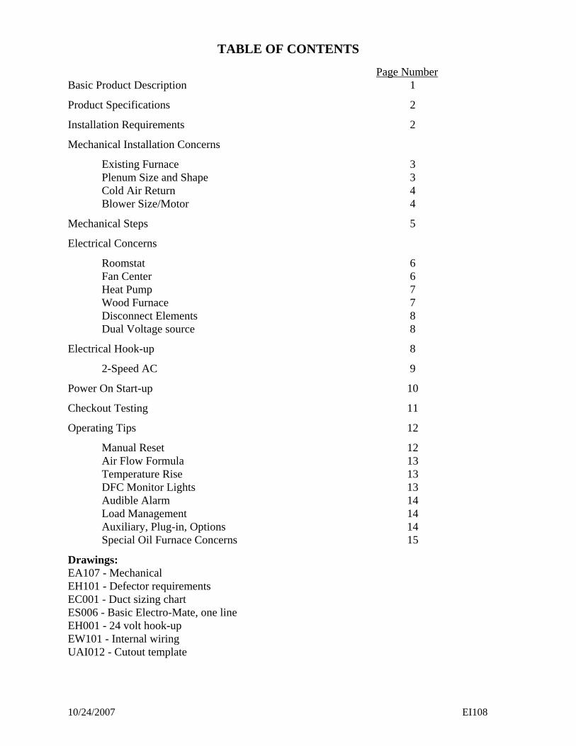
Width 8 = 18” EM-LV **YZW 5 = 15” kW 1st Capacity 10 = 10kW 7 = 7.5kW 15 = 15kW 1 = 10kW 20 = 20kW Stages 1 = 1 2 = 2
U.S. and Canadian patent apply No. 4,593,176 and No. 1,177,512.
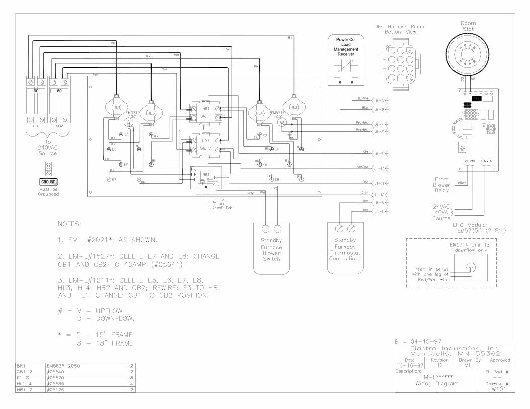
Note: This model now includes 250°F manual hi-limit reset, located behind the hinged controller board door. Drawings: EA107 EH101 EC001 ES006 EH001 EW101
10/24/2007 EI108
TABLE OF CONTENTS
Page Number
Basic Product Description 1
Product Specifications 2
Installation Requirements 2
Mechanical Installation Concerns
Existing Furnace 3 Plenum Size and Shape 3 Cold Air Return 4 Blower Size/Motor 4
Mechanical Steps 5
Electrical Concerns
Roomstat 6 Fan Center 6 Heat Pump 7 Wood Furnace 7 Disconnect Elements 8 Dual Voltage source 8
Electrical Hook-up 8
2-Speed AC 9
Power On Start-up 10
Checkout Testing 11
Operating Tips 12
Manual Reset 12 Air Flow Formula 13 Temperature Rise 13 DFC Monitor Lights 13 Audible Alarm 14 Load Management 14 Auxiliary, Plug-in, Options 14 Special Oil Furnace Concerns 15
Drawings: EA107 - Mechanical EH101 - Defector requirements EC001 - Duct sizing chart ES006 - Basic Electro-Mate, one line EH001 - 24 volt hook-up EW101 - Internal wiring UAI012 - Cutout template
10/24/2007 1 EI108
DESCRIPTION
This is a prewired package for converting your existing oil or gas furnace to a dual heating system. When installed according to this instruction manual and inspected by your local power company representative, your dual heating system will qualify for the special off-peak electric or Dual Fuel Kwh rates. This unit can also be used for converting existing fossil furnace to "total electric" operation. Do not attempt to modify internal wiring or delete controls. Simply wire nut the Load Management remote control blue and blue/white wires ("ELECTRICAL HOOKUP") and install according to this manual. This unit is the UPFLOW furnace only. Contact Electro Industries, Inc., for other models. Do NOT install upside down or in the furnace return air duct. Since this is an addition to your existing furnace system, the existing fossil fuel furnace must be in good working condition. It is designed for direct installations on top of any oil/gas furnace or air conditioning A-coil. If installed according to the detail instructions in this manual, airflow problems common with standard duct heaters are eliminated. In approximately 7Ø% of the installations, the only sheet metal experience or work required is the proper location for installation, cutting the hole in the vertical plenum, and for plenums larger than 19"x19" install special air deflector kit (available from Electro Industries, Inc.). This Electro-Mate unit contains several patented mechanical, airflow, and electrical control features. Since these patented features cause this unit to be unique compared to other electric heating products, this installation manual must be studied and followed in detail. During operation, a high frequency warning buzzer indicates a problem with the blower motor or insufficient airflow across the heating elements. Certain accessories may be required to complete this installation. See appropriate section of this manual. This manual also contains a Limited Warranty Statement. Please read and understand conditions associated with proper installation, unauthorized changes, and POWER ON procedures.
Note: Using a 2ØKW unit for all installations is not necessarily a correct decision. The unit must be sized according to the actual heat requirements of the building. Over sizing could result in reduced element life, false hi-limit buzzer, increased wiring costs, unnecessary airflow problems with existing furnace, etc.
10/24/2007 2 EI108
For information, all units are rated at 24Ø volt. When operating at lower source voltage, the output will be reduced. Example: 2ØKW unit, assuming normal element tolerances 22Ø volt source - 16.8KW, 76.4 Amps 2Ø8 volt source - 15.1KW, 72.3 Amps Notice to Homeowner and Installer 1. This model now contains a three minute POWER ON DELAY. 2. If this unit is to be installed in the hot air plenum of a wood furnace, sensor EM5713 must be
installed between the furnace and electric elements. 3. Hi-limit cycling and a warning buzzer two to five minutes after initial turn on usually means
improper deflector or baffle installation or insufficient airflow - carefully study and follow installation suggestions.
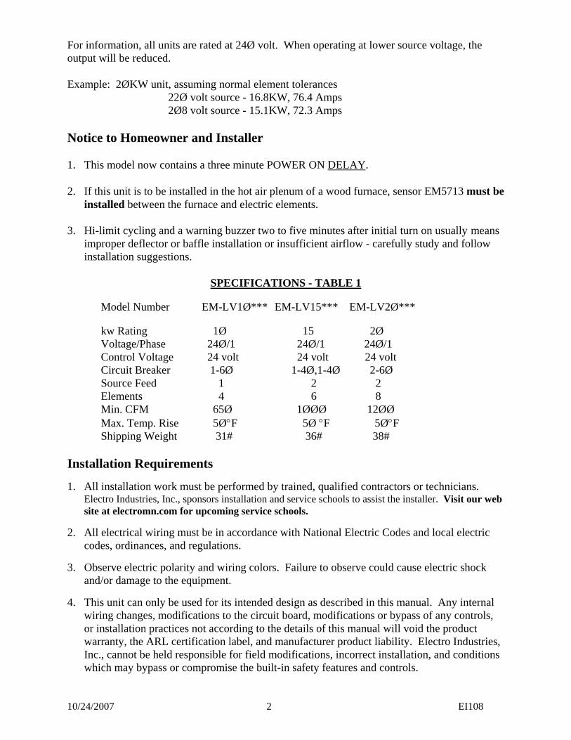
SPECIFICATIONS - TABLE 1
Model Number EM-LV1Ø*** EM-LV15*** EM-LV2Ø*** kw Rating 1Ø 15 2Ø Voltage/Phase 24Ø/1 24Ø/1 24Ø/1 Control Voltage 24 volt 24 volt 24 volt Circuit Breaker 1-6Ø 1-4Ø,1-4Ø 2-6Ø Source Feed 1 2 2 Elements 4 6 8 Min. CFM 65Ø 1ØØØ 12ØØ Max. Temp. Rise 5Ø°F 5Ø °F 5Ø°F Shipping Weight 31# 36# 38#
Installation Requirements
1. All installation work must be performed by trained, qualified contractors or technicians. Electro Industries, Inc., sponsors installation and service schools to assist the installer. Visit our web site at electromn.com for upcoming service schools.
2. All electrical wiring must be in accordance with National Electric Codes and local electric codes, ordinances, and regulations.
3. Observe electric polarity and wiring colors. Failure to observe could cause electric shock and/or damage to the equipment.
4. This unit can only be used for its intended design as described in this manual. Any internal wiring changes, modifications to the circuit board, modifications or bypass of any controls, or installation practices not according to the details of this manual will void the product warranty, the ARL certification label, and manufacturer product liability. Electro Industries, Inc., cannot be held responsible for field modifications, incorrect installation, and conditions which may bypass or compromise the built-in safety features and controls.
10/24/2007 3 EI108
5. This installation manual and Electro-Mate products relate only to the addition of the Electro-Mate plenum heater to the furnace ducting system external to the gas or oil force air furnace. The owner/ installer assumes all responsibility and/or liability associated with any desired or needed installation modification of the gas/oil furnace, fuel system, flue, chimney, etc. Any instructions or comments made within this manual (or factory phone assistance) relating to the gas/oil furnace are provided as comments of assistance and “helps” only.
MECHANICAL
The Electro-Mate is designed to control or compensate for certain airflow problems inherent with tight spacing residential forced air furnace systems. However, the Electro-Mate cannot produce airflow and cannot correct airflow problems inherent within the existing furnace system. The following seven items must be carefully considered and properly followed for all installations:
1. EXAMINATION OF EXISTING FORCED AIR FURNACE - Prior to starting this installation or furnace modification, examine the total furnace system and make necessary comments or recommendations to the homeowner. Remember, if a marginal condition exists within the existing forced air system, the installation of an Electro-Mate will not necessarily cure PRE-EXISTING conditions. Consider such items as proper fossil fuel ignition, is the furnace cycling on hi-limit, filter, adequate cold air return, adequate supply duct and room register (1 register per 100 CFM) etc.
2. FURNACE TYPE - This unit must be installed in an UPFLOW only. Do not turn the Electro-Mate upside down or install this unit in the cold air return. 3. HEATING CAPACITY - Size the Electro-Mate according to the normal heating
requirements as the building exists today. Do not necessarily match to the existing furnace because it may be oversized. Do not oversize the Electro-Mate.
4. SUPPLY PLENUM - Carefully examine all sides of the plenum. Visualize an ideal
location for the Electro-Mate and follow all the details of the appropriate installation diagram. Verify all transitions have angles less than 3Ø°, the Electro-Mate is centered within the plenum, and there are no odd shaped angles or odd shaped transitions within the plenum. One or more of the following will apply:
A. No A-Coil - Follow drawing EA1Ø7, except A-coil is not present. Notice all
distribution ducts or pipes must be above Electro-Mate elements with 1Ø" minimum clearance at top. If lots of height is available, center unit between furnace top and lowest take-off duct.
B. Air Conditioning A-Coil - Follow Drawing EA1Ø7. The Electro-Mate must
be above A-coil and parallel to A-coil. Again, all distribution ducts must be above the Electro-Mate.
C. Width or DEPTH too small - Build out both sides or back with a 3Ø°
transition. Do not build out the Electro-Mate mounting front. The build-out should be as high as possible so that the elements do not set in a pocket. Also 15" wide model is available, see sales sheet and price list.
10/24/2007 4 EI108
Note: Do not use a 15" model in plenums larger than 18"x18". This is especially true when installing over an A-coil. The elements must be located at and close to the sides of the plenum.
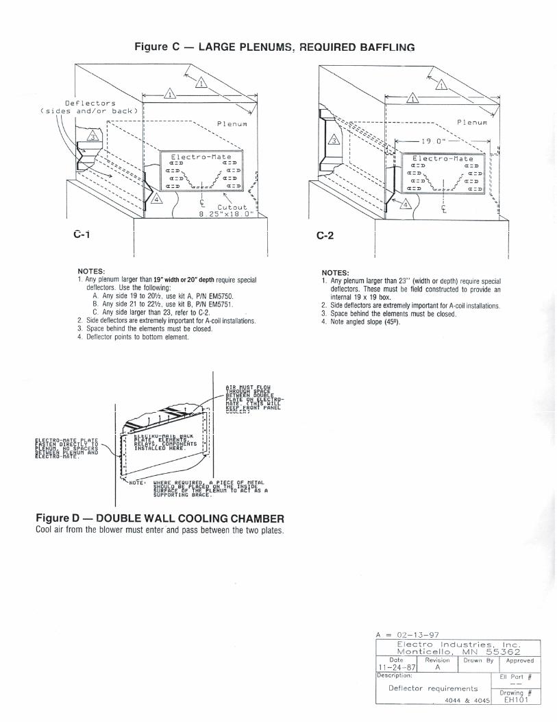
D. Width or DEPTH greater than 19" - Only use 18" model and follow drawing
EH1Ø1 (C-1 and C-2). Do not build-out or build-in the Electro-Mate mounting (see EH1Ø1). Ideally all plenums should be built-in so that the Electro-Mate is inserted into 19"x19" box. The mounting plate or control box of the Electro-Mate must be flat with the existing plenum. The "V" deflectors shown on EH1Ø1 (C-1) should be used only with proper experience and where an oversized blower is available. If plenum is too wide, build-in must be on both sides, equally.
Note: Some plenums may require a full vertical deflector, drawing EH1Ø1
(C-2) in the back and possibly a "V" deflector, EH1Ø1 (C-1) on each side.
E. Plenum access, hot objects - Electro-Mate control box must be at least 12" from flue pipe or other hot objects.
5. OTHER PLENUM EQUIPMENT - Auxiliary equipment such as humidifiers, plenum
dampers, etc., located within the plenum which may cause a non-uniform airflow will have to be removed. Zone dampers within the trunk line at least 12" from the Electro-Mate typically are no problem. Verify that when the dampers are opened and closed, they do not result in an unbalanced airflow across the Electro-Mate or a turbulence effect at the Electro-Mate elements. When horizontal duct dampers are involved, perform all check-out functions with smallest zone open first.
6. INSUFFICIENT COLD AIR RETURN CAPACITY - Installation experience indicates
this is a major concern. In fact, it could represent a problem in as many as 6Ø% of the installations, especially if there is a requirement to increase airflow with the existing blower and the existing cold air return capacity is already undersized or restricted. Check the static pressure within the return cabinet or the suction at the filter cabinet door. Do not assume because there is a register on the wall, the hole behind the register or the passageways are equal to this register. Sharp offsets and transitions in the cold air return system often cause severe restrictions. Expect to add additional registers or a relief register in the main cold air return duct. See the "POWER ON START-UP" section to assist in identifying this concern.
7. BLOWER CFM CAPACITY - The furnace forced air system must have an airflow
capacity larger than the minimum requirement on an Electro-Mate specification sheet (see "SPECIFICATIONS - TABLE 1") or the Electro-Mate nameplate. It is near impossible to correctly measure CFM airflow in an existing residential installation. Experience and rule of thumb indicators will have to be followed to determine the existing furnace CFM capacity. The following may be helpful:
A. Existing furnace nameplate - Typically represents a high or optimistic rating and is a function of the systems static pressure. What changes have been made to the furnace since it left the manufacturing plant?
B. Blower motor size - Used only as a minimal guide.
10/24/2007 5 EI108
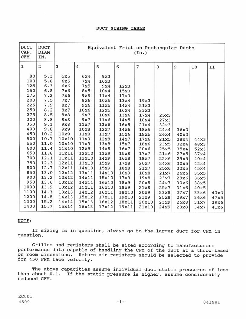
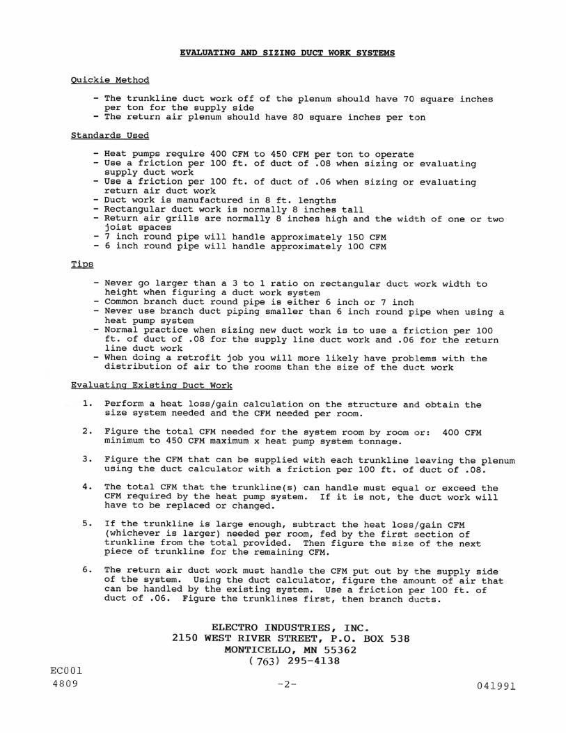
1ØKW unit - 1/5 HP or larger 15KW unit - 1/4 HP or larger 2ØKW unit - 1/3 HP or larger C. Observe/examine airflow ducting system and design - Use duct sizing table
(ECØØ1), or industry equivalent duct capacity airflow charts and determine if the system is capable of delivery the CFM required on the nameplate. Especially check the number of registers and the number of “6 inch rounds”. The same would apply to cold air return duct capacity.
D. Equipped or designed for air conditioning - Airflow systems updated or
designed for three ton or larger air conditioning should have sufficient airflow.
E. Calculated CFM - By measuring the temperature rise across the existing furnace (or this electric unit), the CFM can be approximated. The accuracy of this formula will depend upon the estimated or determined Btu output (actual heat energy across the furnace). You cannot use nameplate Btu values. You must use a realistic estimated or measured true OUTPUT Btu.
Btu (output) Temp. Rise x 1.08
MECHANICAL INSTALLATION
If all the previous items have been verified and followed in detail, the actual installation involves the following steps: Note: For maximum performance and maximum element life, this unit must be
installed in the furnace hot air plenum such that there is uniform airflow across each element and maximum airflow across the entire element surfaces.
The Electro-Mate is designed with a special double plate at the element mounting. Cool air from the blower must blow between these two plates. Therefore, the Elector-Mate must be inserted into the base plenum such that the mounting plate is even with the edge of the hot air outlet hole. Do not necessarily line up the Electro-Mate control box with the furnace cabinet front. The concern is the hole in the bottom of the furnace mating with Electro-Mate elements. 1. Cutting the correct hole size in the plenum – locate the supplied cutout template marked
“UAI012”. Once placement of the Electro-Mate is determined, tape all four corners of the template to the plenum. Make sure that the template is squared off to the plenum before proceeding to the next step. Using a utility knife cut out the appropriate dashed line on the template. Then use a marker to trace around the area cut out of the template. Remove the template from the plenum and proceed to cut the hole into the plenum.
2. Install the necessary deflectors or plenum build-in as outlined in paragraph 4, previous section. 3. Use a light or flashlight to check the top of the furnace, around the furnace heat exchanger,
position of the A-coil, the cleanliness of the A-coil, and any conditions within the furnace system, which would result in a non-uniform airflow at any of the electric elements.
CFM=
10/24/2007 6 EI108
4. If required, install plenum strengthening bars or S-clips. Verify there are no flanges or obstructions around the opening to prevent air from entering the Electro-Mate double plate air cooler, see EC1Ø7. If vertical strengthening bars are used they must be placed on the inside surface of the plenum.
5. Extend the Electro-Mate "V" channel to butt against the plenum back surface or the installed
deflector opposite the cut-in hole. 6. When handling or inserting the actual Electro-Mate unit, verify the element or the element
fins do not become bent and the sensor probe is parallel with the top element. These probes must be approximately 1½" from element fin.
7. Insert the Electro-Mate unit with the sensor probes at the top or above the element by
hooking in the bottom mounting plate first. This should catch the bottom of the plenum hole opening and hold in place while starting the top screws (observe airflow arrow inside control box).
8. Verify that there is a tight air seal around the complete Electro-Mate unit and there are no
obstructions for airflow into the double plate cooling chamber, see EC1Ø7.
Note: If the mechanical contractor has responsibility for this job (sold the unit), he must return to perform the POWER ON start-up test and fill out the certification data sheet. The job is not complete until there is thorough verification of proper operation.
ELECTRICAL
Prior to starting the electric wiring, evaluate the following items:
1. QUALITY AND TYPE OF ROOM THERMOSTAT - The room thermostat can be any 24
volt, adjustable heat anticipator, single stage unit. Set the heat anticipator to Ø.2. Do not use a 2 stage roomstat or 2 thermostats for this Dual Heat system. The DFC module takes care of all switch over, Load Management interrupt, and matching of 1 thermostat to both heating sources. If you feel you need to use 2 stage stat or 2 thermostats, call the factory for special instructions.
2. AIR CONDITIONING SUB-BASE THERMOSTAT - If the existing furnace has a 4 wire
thermostat for controlling the air conditioner and fan switch, wiring colors or polarity of the 24 volt control system must be observed. Reference must be made to the 24 volt system COMMON. This common must be at the bottom right terminal (viewed from the back) of the Dual Fuel Control (DFC) module.
3. FURNACE FAN CENTER OR 24 VOLT SOURCE - Since fan center (transformer and
blower relay) are now quite universal among all furnaces, this manual has been rewritten assuming the standby furnace has a traditional fan center and low voltage wiring matches drawing EHØØ1. If this is not the case, call the factory for assistance. The primary low voltage rules within this dual heat system are:
A. One 24 volt transformer for the entire heating/cooling system. B. Electro-Mate requires 30 VA minimum. C. One 24 volt "common" throughout the system.
10/24/2007 7 EI108
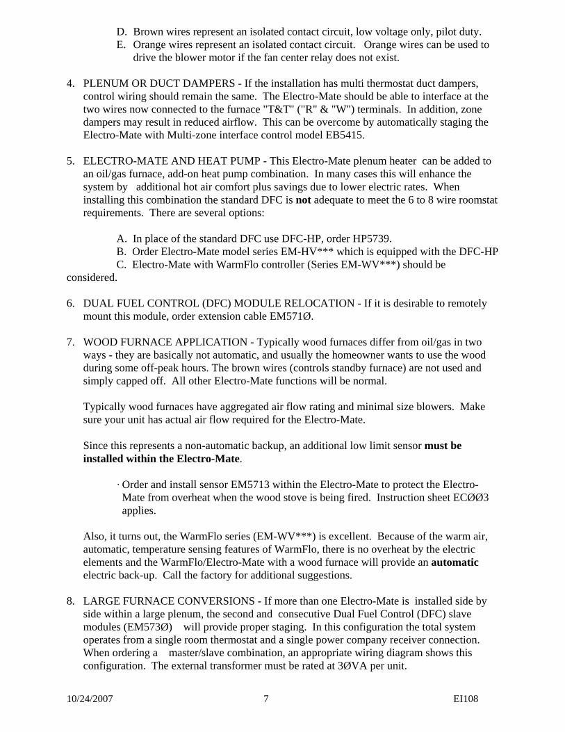
D. Brown wires represent an isolated contact circuit, low voltage only, pilot duty. E. Orange wires represent an isolated contact circuit. Orange wires can be used to
drive the blower motor if the fan center relay does not exist. 4. PLENUM OR DUCT DAMPERS - If the installation has multi thermostat duct dampers,
control wiring should remain the same. The Electro-Mate should be able to interface at the two wires now connected to the furnace "T&T" ("R" & "W") terminals. In addition, zone dampers may result in reduced airflow. This can be overcome by automatically staging the Electro-Mate with Multi-zone interface control model EB5415.
5. ELECTRO-MATE AND HEAT PUMP - This Electro-Mate plenum heater can be added to
an oil/gas furnace, add-on heat pump combination. In many cases this will enhance the system by additional hot air comfort plus savings due to lower electric rates. When installing this combination the standard DFC is not adequate to meet the 6 to 8 wire roomstat requirements. There are several options:
A. In place of the standard DFC use DFC-HP, order HP5739. B. Order Electro-Mate model series EM-HV*** which is equipped with the DFC-HP C. Electro-Mate with WarmFlo controller (Series EM-WV***) should be considered. 6. DUAL FUEL CONTROL (DFC) MODULE RELOCATION - If it is desirable to remotely
mount this module, order extension cable EM571Ø. 7. WOOD FURNACE APPLICATION - Typically wood furnaces differ from oil/gas in two
ways - they are basically not automatic, and usually the homeowner wants to use the wood during some off-peak hours. The brown wires (controls standby furnace) are not used and simply capped off. All other Electro-Mate functions will be normal.
Typically wood furnaces have aggregated air flow rating and minimal size blowers. Make
sure your unit has actual air flow required for the Electro-Mate. Since this represents a non-automatic backup, an additional low limit sensor must be
installed within the Electro-Mate. · Order and install sensor EM5713 within the Electro-Mate to protect the Electro- Mate from overheat when the wood stove is being fired. Instruction sheet ECØØ3 applies. Also, it turns out, the WarmFlo series (EM-WV***) is excellent. Because of the warm air,
automatic, temperature sensing features of WarmFlo, there is no overheat by the electric elements and the WarmFlo/Electro-Mate with a wood furnace will provide an automatic electric back-up. Call the factory for additional suggestions.
8. LARGE FURNACE CONVERSIONS - If more than one Electro-Mate is installed side by
side within a large plenum, the second and consecutive Dual Fuel Control (DFC) slave modules (EM573Ø) will provide proper staging. In this configuration the total system operates from a single room thermostat and a single power company receiver connection. When ordering a master/slave combination, an appropriate wiring diagram shows this configuration. The external transformer must be rated at 3ØVA per unit.
10/24/2007 8 EI108
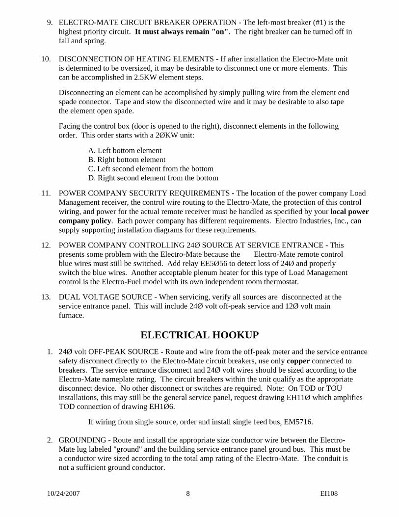
9. ELECTRO-MATE CIRCUIT BREAKER OPERATION - The left-most breaker (#1) is the highest priority circuit. It must always remain "on". The right breaker can be turned off in fall and spring.
10. DISCONNECTION OF HEATING ELEMENTS - If after installation the Electro-Mate unit
is determined to be oversized, it may be desirable to disconnect one or more elements. This can be accomplished in 2.5KW element steps.
Disconnecting an element can be accomplished by simply pulling wire from the element end spade connector. Tape and stow the disconnected wire and it may be desirable to also tape the element open spade.
Facing the control box (door is opened to the right), disconnect elements in the following order. This order starts with a 2ØKW unit:
A. Left bottom element B. Right bottom element C. Left second element from the bottom D. Right second element from the bottom
11. POWER COMPANY SECURITY REQUIREMENTS - The location of the power company Load Management receiver, the control wire routing to the Electro-Mate, the protection of this control wiring, and power for the actual remote receiver must be handled as specified by your local power company policy. Each power company has different requirements. Electro Industries, Inc., can supply supporting installation diagrams for these requirements.
12. POWER COMPANY CONTROLLING 24Ø SOURCE AT SERVICE ENTRANCE - This presents some problem with the Electro-Mate because the Electro-Mate remote control blue wires must still be switched. Add relay EE5Ø56 to detect loss of 24Ø and properly switch the blue wires. Another acceptable plenum heater for this type of Load Management control is the Electro-Fuel model with its own independent room thermostat.
13. DUAL VOLTAGE SOURCE - When servicing, verify all sources are disconnected at the service entrance panel. This will include 24Ø volt off-peak service and 12Ø volt main furnace.
ELECTRICAL HOOKUP
1. 24Ø volt OFF-PEAK SOURCE - Route and wire from the off-peak meter and the service entrance safety disconnect directly to the Electro-Mate circuit breakers, use only copper connected to breakers. The service entrance disconnect and 24Ø volt wires should be sized according to the Electro-Mate nameplate rating. The circuit breakers within the unit qualify as the appropriate disconnect device. No other disconnect or switches are required. Note: On TOD or TOU installations, this may still be the general service panel, request drawing EH11Ø which amplifies TOD connection of drawing EH1Ø6.
If wiring from single source, order and install single feed bus, EM5716. 2. GROUNDING - Route and install the appropriate size conductor wire between the Electro-
Mate lug labeled "ground" and the building service entrance panel ground bus. This must be a conductor wire sized according to the total amp rating of the Electro-Mate. The conduit is not a sufficient ground conductor.
10/24/2007 9 EI108
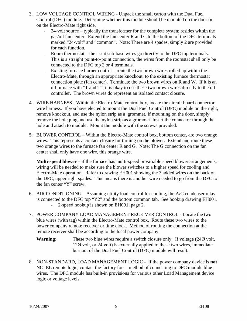
3. LOW VOLTAGE CONTROL WIRING - Unpack the small carton with the Dual Fuel Control (DFC) module. Determine whether this module should be mounted on the door or on the Electro-Mate right side.
- 24-volt source – typically the transformer for the complete system resides within the gas/oil fan center. Extend the fan center R and C to the bottom of the DFC terminals marked “24-volt” and “common”. Note: There are 4 spades, simply 2 are provided for each function.
- Room thermostat – the t-stat sub-base wires go directly to the DFC top terminals. This is a straight point-to-point connection, the wires from the roomstat shall only be connected to the DFC top 2 or 4 terminals.
- Existing furnace burner control – route the two brown wires rolled up within the Electro-Mate, through an appropriate knockout, to the existing furnace thermostat connection plate (fan center). Terminate the two brown wires on R and W. If it is an oil furnace with “T and T”, it is okay to use these two brown wires directly to the oil controller. The brown wires do represent an isolated contact closure.
4. WIRE HARNESS - Within the Electro-Mate control box, locate the circuit board connector wire harness. If you have elected to mount the Dual Fuel Control (DFC) module on the right, remove knockout, and use the nylon strip as a grommet. If mounting on the door, simply
remove the hole plug and use the nylon strip as a grommet. Insert the connector through the hole and attach to module. Mount the module with the screws provided.
5. BLOWER CONTROL – Within the Electro-Mate control box, bottom center, are two orange wires. This represents a contact closure for turning on the blower. Extend and route these two orange wires to the furnace fan center R and G. Note: The G connection on the fan center shall only have one wire, this orange wire.
Multi-speed blower – if the furnace has multi-speed or variable speed blower arrangements, wiring will be needed to make sure the blower switches to a higher speed for cooling and Electro-Mate operation. Refer to drawing EH001 showing the 3 added wires on the back of the DFC, upper right spades. This means there is another wire needed to go from the DFC to the fan center “Y” screw.
6. AIR CONDITIONING – Assuming utility load control for cooling, the A/C condenser relay is connected to the DFC top “Y2” and the bottom common tab. See hookup drawing EH001.
- 2-speed hookup is shown on EH001, page 2.
7. POWER COMPANY LOAD MANAGEMENT RECEIVER CONTROL - Locate the two blue wires (with tag) within the Electro-Mate control box. Route these two wires to the power company remote receiver or time clock. Method of routing the connection at the remote receiver shall be according to the local power company.
Warning: These two blue wires require a switch closure only. If voltage (24Ø volt, 12Ø volt, or 24 volt) is externally applied to these two wires, immediate burnout of the Dual Fuel Control (DFC) module will result. 8. NON-STANDARD, LOAD MANAGEMENT LOGIC - If the power company device is not
NC=EL remote logic, contact the factory for method of connecting to DFC module blue wires. The DFC module has built-in provisions for various other Load Management device logic or voltage levels.
10/24/2007 10 EI108
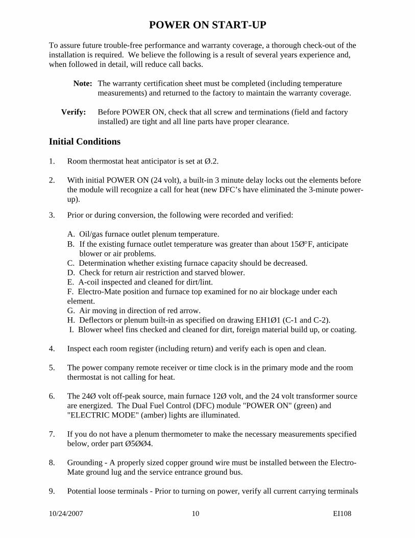
POWER ON START-UP To assure future trouble-free performance and warranty coverage, a thorough check-out of the installation is required. We believe the following is a result of several years experience and, when followed in detail, will reduce call backs. Note: The warranty certification sheet must be completed (including temperature
measurements) and returned to the factory to maintain the warranty coverage. Verify: Before POWER ON, check that all screw and terminations (field and factory
installed) are tight and all line parts have proper clearance. Initial Conditions 1. Room thermostat heat anticipator is set at Ø.2. 2. With initial POWER ON (24 volt), a built-in 3 minute delay locks out the elements before
the module will recognize a call for heat (new DFC’s have eliminated the 3-minute power-up).
3. Prior or during conversion, the following were recorded and verified: A. Oil/gas furnace outlet plenum temperature.
B. If the existing furnace outlet temperature was greater than about 15Ø°F, anticipate blower or air problems.
C. Determination whether existing furnace capacity should be decreased. D. Check for return air restriction and starved blower. E. A-coil inspected and cleaned for dirt/lint. F. Electro-Mate position and furnace top examined for no air blockage under each
element. G. Air moving in direction of red arrow. H. Deflectors or plenum built-in as specified on drawing EH1Ø1 (C-1 and C-2). I. Blower wheel fins checked and cleaned for dirt, foreign material build up, or coating. 4. Inspect each room register (including return) and verify each is open and clean. 5. The power company remote receiver or time clock is in the primary mode and the room thermostat is not calling for heat. 6. The 24Ø volt off-peak source, main furnace 12Ø volt, and the 24 volt transformer source
are energized. The Dual Fuel Control (DFC) module "POWER ON" (green) and "ELECTRIC MODE" (amber) lights are illuminated.
7. If you do not have a plenum thermometer to make the necessary measurements specified
below, order part Ø5ØØ4. 8. Grounding - A properly sized copper ground wire must be installed between the Electro-
Mate ground lug and the service entrance ground bus. 9. Potential loose terminals - Prior to turning on power, verify all current carrying terminals
10/24/2007 11 EI108
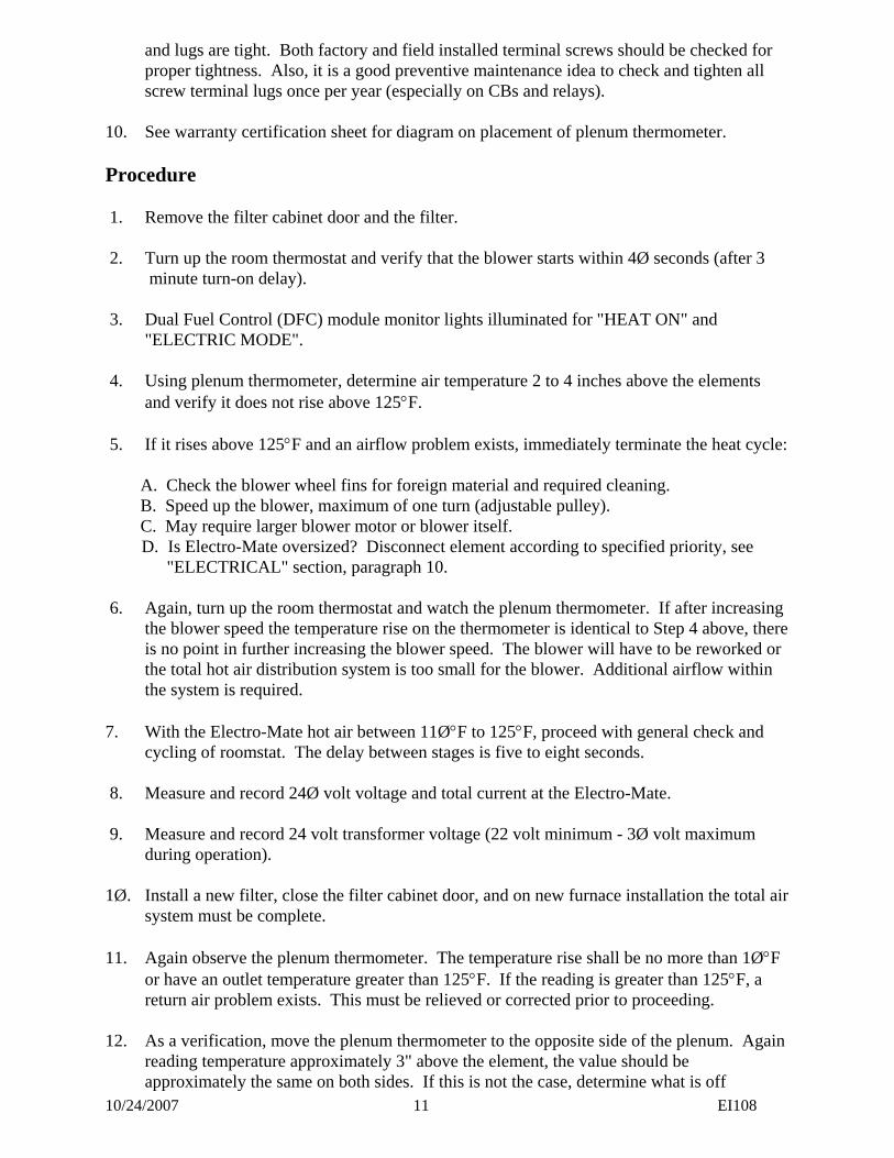
and lugs are tight. Both factory and field installed terminal screws should be checked for proper tightness. Also, it is a good preventive maintenance idea to check and tighten all screw terminal lugs once per year (especially on CBs and relays).
10. See warranty certification sheet for diagram on placement of plenum thermometer. Procedure 1. Remove the filter cabinet door and the filter. 2. Turn up the room thermostat and verify that the blower starts within 4Ø seconds (after 3 minute turn-on delay). 3. Dual Fuel Control (DFC) module monitor lights illuminated for "HEAT ON" and
"ELECTRIC MODE". 4. Using plenum thermometer, determine air temperature 2 to 4 inches above the elements
and verify it does not rise above 125°F. 5. If it rises above 125°F and an airflow problem exists, immediately terminate the heat cycle: A. Check the blower wheel fins for foreign material and required cleaning. B. Speed up the blower, maximum of one turn (adjustable pulley). C. May require larger blower motor or blower itself.
D. Is Electro-Mate oversized? Disconnect element according to specified priority, see "ELECTRICAL" section, paragraph 10.
6. Again, turn up the room thermostat and watch the plenum thermometer. If after increasing
the blower speed the temperature rise on the thermometer is identical to Step 4 above, there is no point in further increasing the blower speed. The blower will have to be reworked or the total hot air distribution system is too small for the blower. Additional airflow within the system is required.
7. With the Electro-Mate hot air between 11Ø°F to 125°F, proceed with general check and
cycling of roomstat. The delay between stages is five to eight seconds. 8. Measure and record 24Ø volt voltage and total current at the Electro-Mate. 9. Measure and record 24 volt transformer voltage (22 volt minimum - 3Ø volt maximum
during operation). 1Ø. Install a new filter, close the filter cabinet door, and on new furnace installation the total air
system must be complete. 11. Again observe the plenum thermometer. The temperature rise shall be no more than 1Ø°F
or have an outlet temperature greater than 125°F. If the reading is greater than 125°F, a return air problem exists. This must be relieved or corrected prior to proceeding.
12. As a verification, move the plenum thermometer to the opposite side of the plenum. Again
reading temperature approximately 3" above the element, the value should be approximately the same on both sides. If this is not the case, determine what is off
10/24/2007 12 EI108
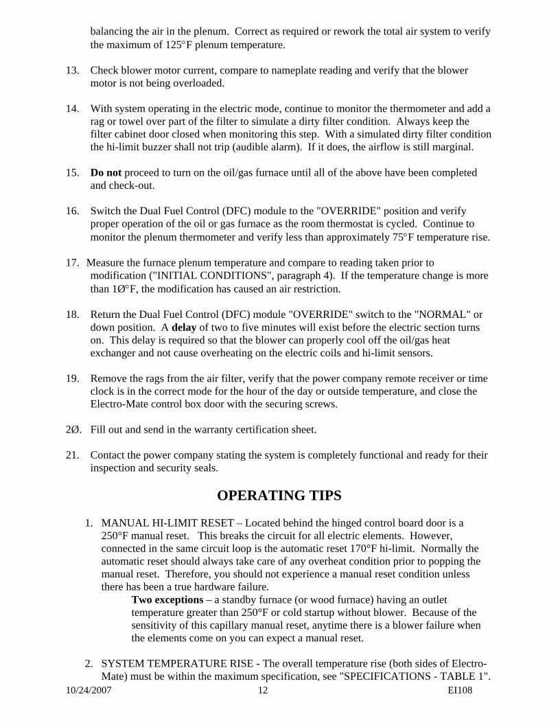
balancing the air in the plenum. Correct as required or rework the total air system to verify the maximum of 125°F plenum temperature.
13. Check blower motor current, compare to nameplate reading and verify that the blower
motor is not being overloaded. 14. With system operating in the electric mode, continue to monitor the thermometer and add a
rag or towel over part of the filter to simulate a dirty filter condition. Always keep the filter cabinet door closed when monitoring this step. With a simulated dirty filter condition the hi-limit buzzer shall not trip (audible alarm). If it does, the airflow is still marginal.
15. Do not proceed to turn on the oil/gas furnace until all of the above have been completed
and check-out. 16. Switch the Dual Fuel Control (DFC) module to the "OVERRIDE" position and verify
proper operation of the oil or gas furnace as the room thermostat is cycled. Continue to monitor the plenum thermometer and verify less than approximately 75°F temperature rise.
17. Measure the furnace plenum temperature and compare to reading taken prior to
modification ("INITIAL CONDITIONS", paragraph 4). If the temperature change is more than 1Ø°F, the modification has caused an air restriction.
18. Return the Dual Fuel Control (DFC) module "OVERRIDE" switch to the "NORMAL" or
down position. A delay of two to five minutes will exist before the electric section turns on. This delay is required so that the blower can properly cool off the oil/gas heat exchanger and not cause overheating on the electric coils and hi-limit sensors.
19. Remove the rags from the air filter, verify that the power company remote receiver or time
clock is in the correct mode for the hour of the day or outside temperature, and close the Electro-Mate control box door with the securing screws.
2Ø. Fill out and send in the warranty certification sheet. 21. Contact the power company stating the system is completely functional and ready for their
inspection and security seals.
OPERATING TIPS
1. MANUAL HI-LIMIT RESET – Located behind the hinged control board door is a 250°F manual reset. This breaks the circuit for all electric elements. However, connected in the same circuit loop is the automatic reset 170°F hi-limit. Normally the automatic reset should always take care of any overheat condition prior to popping the manual reset. Therefore, you should not experience a manual reset condition unless there has been a true hardware failure.
Two exceptions – a standby furnace (or wood furnace) having an outlet temperature greater than 250°F or cold startup without blower. Because of the sensitivity of this capillary manual reset, anytime there is a blower failure when the elements come on you can expect a manual reset.
2. SYSTEM TEMPERATURE RISE - The overall temperature rise (both sides of Electro-
Mate) must be within the maximum specification, see "SPECIFICATIONS - TABLE 1".
10/24/2007 13 EI108
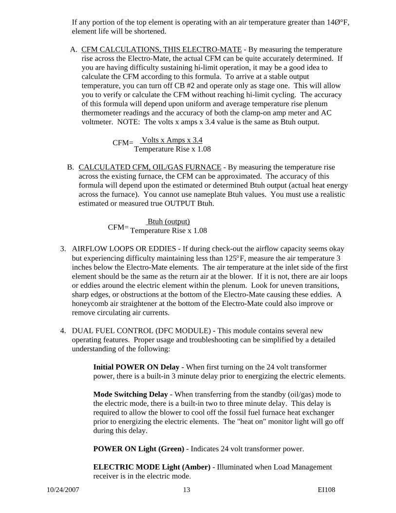
If any portion of the top element is operating with an air temperature greater than 14Ø°F, element life will be shortened.
A. CFM CALCULATIONS, THIS ELECTRO-MATE - By measuring the temperature
rise across the Electro-Mate, the actual CFM can be quite accurately determined. If you are having difficulty sustaining hi-limit operation, it may be a good idea to calculate the CFM according to this formula. To arrive at a stable output temperature, you can turn off CB #2 and operate only as stage one. This will allow you to verify or calculate the CFM without reaching hi-limit cycling. The accuracy of this formula will depend upon uniform and average temperature rise plenum thermometer readings and the accuracy of both the clamp-on amp meter and AC voltmeter. NOTE: The volts x amps x 3.4 value is the same as Btuh output.
Volts x Amps x 3.4 Temperature Rise x 1.08
B. CALCULATED CFM, OIL/GAS FURNACE - By measuring the temperature rise across the existing furnace, the CFM can be approximated. The accuracy of this formula will depend upon the estimated or determined Btuh output (actual heat energy across the furnace). You cannot use nameplate Btuh values. You must use a realistic estimated or measured true OUTPUT Btuh.
Btuh (output) Temperature Rise x 1.08
3. AIRFLOW LOOPS OR EDDIES - If during check-out the airflow capacity seems okay but experiencing difficulty maintaining less than 125°F, measure the air temperature 3 inches below the Electro-Mate elements. The air temperature at the inlet side of the first element should be the same as the return air at the blower. If it is not, there are air loops or eddies around the electric element within the plenum. Look for uneven transitions, sharp edges, or obstructions at the bottom of the Electro-Mate causing these eddies. A honeycomb air straightener at the bottom of the Electro-Mate could also improve or remove circulating air currents.
4. DUAL FUEL CONTROL (DFC MODULE) - This module contains several new
operating features. Proper usage and troubleshooting can be simplified by a detailed understanding of the following:
Initial POWER ON Delay - When first turning on the 24 volt transformer
power, there is a built-in 3 minute delay prior to energizing the electric elements. Mode Switching Delay - When transferring from the standby (oil/gas) mode to
the electric mode, there is a built-in two to three minute delay. This delay is required to allow the blower to cool off the fossil fuel furnace heat exchanger prior to energizing the electric elements. The "heat on" monitor light will go off during this delay.
POWER ON Light (Green) - Indicates 24 volt transformer power. ELECTRIC MODE Light (Amber) - Illuminated when Load Management
receiver is in the electric mode.
CFM=
CFM=
10/24/2007 14 EI108
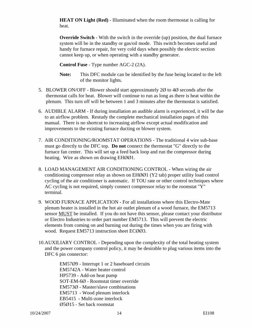
HEAT ON Light (Red) - Illuminated when the room thermostat is calling for
heat. Override Switch - With the switch in the override (up) position, the dual furnace
system will be in the standby or gas/oil mode. This switch becomes useful and handy for furnace repair, for very cold days when possibly the electric section cannot keep up, or when operating with a standby generator.
Control Fuse - Type number AGC-2 (2A).
Note: This DFC module can be identified by the fuse being located to the left of the monitor lights.
5. BLOWER ON/OFF - Blower should start approximately 2Ø to 4Ø seconds after the thermostat calls for heat. Blower will continue to run as long as there is heat within the plenum. This turn off will be between 1 and 3 minutes after the thermostat is satisfied.
6. AUDIBLE ALARM - If during installation an audible alarm is experienced, it will be due to an airflow problem. Restudy the complete mechanical installation pages of this manual. There is no shortcut to increasing airflow except actual modification and improvements to the existing furnace ducting or blower system.
7. AIR CONDITIONING/ROOMSTAT OPERATIONS - The traditional 4 wire sub-base
must go directly to the DFC top. Do not connect the thermostat "G" directly to the furnace fan center. This will set up a feed back loop and run the compressor during heating. Wire as shown on drawing EHØØ1.
8. LOAD MANAGEMENT AIR CONDITIONING CONTROL - When wiring the air
conditioning compressor relay as shown on EHØØ1 (Y2 tab) proper utility load control cycling of the air conditioner is automatic. If TOU rate or other control techniques where AC cycling is not required, simply connect compressor relay to the roomstat "Y" terminal.
9. WOOD FURNACE APPLICATION - For all installations where this Electro-Mate plenum heater is installed in the hot air outlet plenum of a wood furnace, the EM5713 sensor MUST be installed. If you do not have this sensor, please contact your distributor or Electro Industries to order part number EM5713. This will prevent the electric elements from coming on and burning out during the times when you are firing with wood. Request EM5713 instruction sheet ECØØ3.
10.AUXILIARY CONTROL - Depending upon the complexity of the total heating system
and the power company control policy, it may be desirable to plug various items into the DFC 6 pin connector:
EM57Ø9 - Interrupt 1 or 2 baseboard circuits EM5742A - Water heater control HP5739 - Add-on heat pump SOT-EM-6Ø - Roomstat timer override EM573Ø - Master/slave combinations EM5713 - Wood plenum interlock EB5415 - Multi-zone interlock Ø5Ø15 - Set back roomstat
10/24/2007 15 EI108
EM5716 - Single feed bus EM575Ø - Plenum defector kit A EM5751 - Plenum defector kit B PI-ØA1DYMØ - Load shed interlock, stage 2
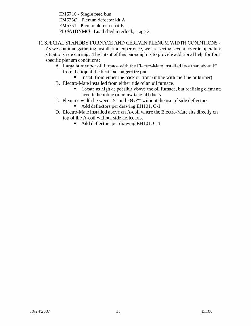
11.SPECIAL STANDBY FURNACE AND CERTAIN PLENUM WIDTH CONDITIONS - As we continue gathering installation experience, we are seeing several over temperature situations reoccurring. The intent of this paragraph is to provide additional help for four specific plenum conditions:
A. Large burner pot oil furnace with the Electro-Mate installed less than about 6" from the top of the heat exchanger/fire pot.
Install from either the back or front (inline with the flue or burner) B. Electro-Mate installed from either side of an oil furnace.
Locate as high as possible above the oil furnace, but realizing elements need to be inline or below take off ducts
C. Plenums width between 19" and 2ؽ"" without the use of side deflectors. Add deflectors per drawing EH101, C-1
D. Electro-Mate installed above an A-coil where the Electro-Mate sits directly on top of the A-coil without side deflectors.
Add deflectors per drawing EH101, C-1
OFFSET TAKEOFF CAN BE3" BELOW EM TOP CUTOUTELECTRO-MATE
10" MINIMUM FROMTOP OF EM CUTOUT Duct
Dist.
DuctDist.
CORNER MUST BEEM TOP CUTOUT
A-Coil
Upflow Only
1
5
4
2
6
3
7
8
15-17.5"18-19"
WIDTH
AMPS x VOLTS x 3.414CFM =
1.08 x TEMP. DIFF.
17.5-19"17.5-19"
DEPTH15" MODEL18" MODEL
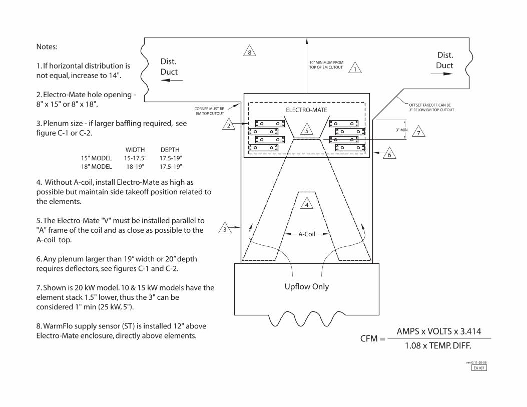
4. Without A-coil, install Electro-Mate as high as possible but maintain side takeoff position related to the elements.
5. The Electro-Mate "V" must be installed parallel to "A" frame of the coil and as close as possible to the A-coil top.
6. Any plenum larger than 19” width or 20” depth requires deflectors, see figures C-1 and C-2.
7. Shown is 20 kW model. 10 & 15 kW models have the element stack 1.5" lower, thus the 3" can be considered 1" min (25 kW, 5").
8. WarmFlo supply sensor (ST) is installed 12" above Electro-Mate enclosure, directly above elements.
Notes:
1. If horizontal distribution is not equal, increase to 14".
2. Electro-Mate hole opening - 8" x 15" or 8" x 18".
3. Plenum size - if larger baffling required, seefigure C-1 or C-2. 3" MIN.
EA107rev.G 11-20-08
19” width or 20” depth
ES006rev.D 09-05-02
METERKWH
CO
MM
ON
OR
AN
GE
24V
AC
FAN CENTER
MATEELECTRO-
OR
AN
GE
FURNACESTAND-BYEXISTING OR
BR
OW
N
BR
OW
N
SEE DETAIL A
DFC
C YRWG
G YR W
ROOM STAT
BLU
E
BLU
/WH
T
LMC
COMMONDFC II24 VAC
4
1
37
8
6
26060
COMNO
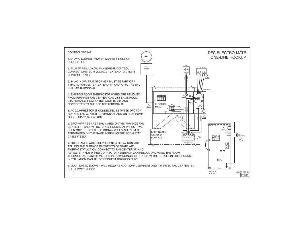
CONTROL WIRING
1. 240VAC ELEMENT POWER CAN BE SINGLE OR DOUBLE FEED.
2. BLUE WIRES, LOAD MANAGEMENT CONTROL CONNECTIONS, LOW VOLTAGE - EXTEND TO UTILITY CONTROL DEVICE.
3. 24VAC, 40VA, TRANSFORMER MUST BE PART OF A TYPICAL FAN CENTER. EXTEND "R" AND "C" TO THE DFC BOTTOM TERMINALS
4. EXISTING ROOM THERMOSTAT WIRES ARE REMOVED FROM FURNACE FAN CENTER (CAN USE SAME ROOM STAT, CHANGE HEAT ANTICIPATOR TO 0.2) AND CONNECTED TO THE DFC TOP TERMINALS.
5. AC COMPRESSOR IS CONNECTED BETWEEN DFC TOP "Y2" AND FAN CENTER "COMMON". IF ADD-ON HEAT PUMP, ORDER HP-5739 CONTROL.
6. BROWN WIRES ARE TERMINATED ON THE FURNACE FAN CENTER "R" AND "W." NOTE: ALL ROOM STAT WIRES HAVE BEEN MOVED TO DFC, THE BROWN WIRES ARE NEVER TERMINATED ON THE SAME SCREW AS THE ROOM STAT CABLE ITSELF.
7. THE ORANGE WIRES REPRESENT A RELAY CONTACT TELLING THE FURNACE BLOWER TO OPERATE WITH THERMOSTAT ACTION. CONNECT TO FAN CENTER "R" AND "G". NOTE: IF NOT WIRED CORRECTLY, FEEDBACK CAN RESULT, DAMAGING THE ROOM THERMOSTAT, BLOWER MOTOR SPEED WINDINGS, ETC. FOLLOW THE DETAILS IN THE PRODUCT INSTALLATION MANUAL OR REQUEST DRAWING EH001.
8. MULTI-SPEED BLOWER WILL REQUIRE ADDITIONAL JUMPERS AND A WIRE TO FAN CENTER "Y", SEE DRAWING EH001.
DFC ELECTRO-MATEONE-LINE HOOKUP
CONDENSERA/C
SCALE 2:1DETAIL A
DFC
A
V+STG4
COM
COMMONDFC II24 VAC
BLNC
NO
COM
SBEL
Y2 X1W G YR
5
8
ELECTRO INDUSTRIES, INC.MONTICELLO, MN 55362
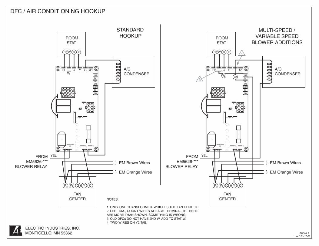
DFC / AIR CONDITIONING HOOKUP
EH001 P1rev.F 01-17-06
J3
T7
T8
J1
J2
F1
BZ1
FCW G
DFC
CSUPCB5609D
LED2
LED3
LED1
SW1
J3
T7
T8
J1
J2
F1
BZ1
FCW G
DFC
CSUPCB5609D
LED2
LED3
LED1
SW1
EM Orange Wires
EM Brown Wires}
}
MULTI-SPEED /VARIABLE SPEED
BLOWER ADDITIONS
}
}
EM Brown Wires
EM Orange Wires
STANDARDHOOKUP
FROMEM5626-***
BLOWER RELAY
A/CCONDENSER
A/CCONDENSER
FROMEM5626-***
BLOWER RELAY
RW
G Y Y2 X1
YEL YEL
NO
BL
NC
COM
W2
EL
SB
NO
BL
NC
COM
W2
EL
SB
6 312 9
6 3A
V+
4 1
4 110 7
STG4
COMMON24 VAC
69 312
6 3A
47 110
STG4 V+
4 1
COMMON24 VAC
ROOMSTAT
R G Y X1
ROOMSTAT
FANCENTER NOTES:
1. ONLY ONE TRANSFORMER. WHICH IS THE FAN CENTER.2. LEFT DIA., COUNT WIRES AT EACH TERMINAL, IF THERE ARE MORE THAN SHOWN, SOMETHING IS WRONG.3. OLD DFCs DO NOT HAVE 2ND W. ADD TO STAT W.4. TWO WIRES ON Y2 TAB.
W
WR YG
R W G Y C
FANCENTER
R W G Y C
WR YG
Y23
4
ELECTRO INDUSTRIES, INC.MONTICELLO, MN 55362
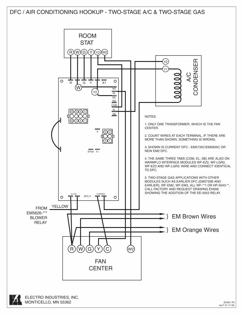
DFC / AIR CONDITIONING HOOKUP - TWO-STAGE A/C & TWO-STAGE GAS
EH001 P2rev.F 01-17-06
NOTES:
1. ONLY ONE TRANSFORMER, WHICH IS THE FAN CENTER.
2. COUNT WIRES AT EACH TERMINAL. IF THERE ARE MORE THAN SHOWN, SOMETHING IS WRONG.
3. SHOWN IS CURRENT DFC - EM5735C/EM5835C OR NEW EM2 DFC.
4. THE SAME THREE TABS (COM, EL, SB) ARE ALSO ON WARMFLO INTERFACE MODULES WF-EZ2, WF-LGR2, WF-EZ3 AND WF-LGR3. WIRE AND CONNECT IDENTICAL TO DFC.
5. TWO-STAGE GAS APPLICATIONS WITH OTHER MODULES SUCH AS EARLIER DFC (EM5735B AND EARLIER), WF-EM2, WF-EM3, ALL WF-**1 OR HP-5043-**, CALL FACTORY AND REQUEST DRAWING EH006 SHOWING THE ADDITION OF THE EE-5053 RELAY.
EM Orange Wires
EM Brown Wires}
}
A/C
CO
ND
EN
SE
R
FROMEM5626-***
BLOWERRELAY
YELLOW
BL
NO
COM
W2
EL
NC
SB69 312
6 3A
47 110
STG4 V+
4 1
COMMON24 VACDFC II
R G Y X1
ROOMSTAT
W
FANCENTER
R W G Y C W2
WR YG Y2
Y1
Y2
W2
Y2
60 60
Power Co.Load
ManagementReceiver
50
60 70
80
50
60 70
80
Page 1 of 2 XX017
Electro Industries, Inc.
Limited Product Warranty Effective February 5, 2009
Electro Industries, Inc. warrants to the original owner, at the original installation site, for a period of two (2) years from date of installation, that the product and product parts manufactured by Electro Industries are free from manufacturing defects in materials and workmanship, when used under normal conditions and when such product has not been modified or changed in any manner after leaving the plant of Electro Industries. If any product or product parts manufactured by Electro Industries are found to have manufacturing defects in materials or workmanship, such will be repaired or replaced by Electro Industries. Electro Industries shall have the opportunity to directly, or through its authorized representative, examine and inspect the alleged defective product or product parts. Electro Industries may request that the materials be returned to Electro Industries at the owner’s expense for factory inspection. The determination as to whether product or product parts shall be repaired, or in the alternative replaced, shall be made by Electro Industries or its authorized representative. Electro Industries will cover reasonable labor costs to repair defective product or product parts for ninety (90) days after installation. TWENTY YEAR (20) LIMITED WARRANTY ON BOILER ELEMENTS AND VESSELS Electro Industries, Inc. warrants that the boiler elements and vessels of its products are free from defects in materials and workmanship through the twentieth year following date of installation. If any boiler elements or vessels are found to have a manufacturing defect in materials or workmanship, Electro Industries will replace them.
TWENTY YEAR (20) LIMITED WARRANTY ON SPIN FIN ELEMENTS Electro Industries, Inc. warrants that the spin fin elements of its products are free from defects in materials and workmanship through the twentieth year following date of installation. If any spin fin elements are found to have a manufacturing defect in materials or workmanship, Electro Industries will replace them.
FIVE YEAR (5) LIMITED WARRANTY ON OPEN WIRE ELEMENTS Electro Industries, Inc. warrants that the open wire elements of its products are free from defects in materials and workmanship through the fifth year following date of installation. If any open wire elements are found to have a manufacturing defect in materials or workmanship, Electro Industries will replace them.
Page 2 of 2 XX017
THESE WARRANTIES DO NOT COVER: 1. Costs for labor for removal and reinstallation of an alleged defective product or product parts,
transportation to Electro Industries, and any other materials necessary to perform the exchange, except as stated in this warranty. Replacement material will be invoiced to the distributor in the usual manner and will be subject to adjustment upon verification of defect.
2. Any product that has been damaged as a result of being improperly serviced or operated, including, but not limited to, the following: operated with insufficient water or airflow, allowed to freeze, subjected to flood conditions, subjected to improper voltages or power supplies, operated with airflow or water conditions and/or fuels or additives which cause unusual deposits or corrosion in or on the product, chemical or galvanic erosion, improper maintenance or subject to any other abuse or negligence.
3. Any product that has been damaged as a result of natural disasters, including, but not limited to, the following: lightning, fire, earthquake, hurricanes, tornadoes or floods.
4. Any product that has been damaged as a result of shipment or handling by the freight carrier. It is the receiver’s responsibility to claim and process freight damage with the carrier.
5. Any product that has been defaced, abused, or suffered unusual wear and tear as determined by Electro Industries or its authorized representative.
6. Workmanship of any installer of the product. This warranty does not assume any liability of any nature for unsatisfactory performance caused by improper installation.
7. Transportation charges for any replacement part or component, service calls, normal maintenance; replacement of fuses, filters, refrigerant, etc.
CONDITIONS AND LIMITATIONS: 1. If at the time of a request for service the original owner cannot provide an original sales receipt or a
warranty card registration then the warranty period for the product will have deemed to begin thirty (30) days after the date of manufacture and NOT the date of installation.
2. The product must have been sold and installed by a licensed electrical contractor, a licensed plumbing contractor, or a licensed heating contractor.
3. The application and installation of the product must be in compliance with Electro Industries’ specifications as stated in the installation and instruction manual, and all state and federal codes and statutes. If not, the warranty will be null and void.
4. The purchaser shall have maintained the product in accordance with the manual that accompanies the unit. Annually, a qualified and licensed contractor must inspect the product to assure it is in proper working condition.
5. All related heating components must be maintained in good operating condition. 6. All lines must be checked to confirm that all condensation drains properly from the unit. 7. Replacement of a product or product part under this limited warranty does not extend the warranty
term or period. 8. Replacement product parts are warranted to be free from defects in material and workmanship for
ninety (90) days from the date of installation. All exclusions, conditions, and limitations expressed in this warranty apply.
9. Before warranty claims will be honored, Electro Industries shall have the opportunity to directly, or through its authorized representative, examine and inspect the alleged defective product or product parts. Remedies under this warranty are limited to repairing or replacing alleged defective product or product parts. The decision whether to repair or, in the alternative replace, products or product parts shall be made by Electro Industries or its authorized representative.
THESE WARRANTIES DO NOT EXTEND TO ANYONE EXCEPT THE ORIGINAL PURCHASER AT RETAIL AND ONLY WHEN THE PRODUCT IS IN THE ORIGINAL INSTALLATION SITE. THE REMEDIES SET FORTH HEREIN ARE EXCLUSIVE.
ALL IMPLIED WARRANTIES, INCLUDING WARRANTIES OF MERCHANTABILITY AND FITNESS FOR A PARTICULAR PURPOSE, ARE HEREBY DISCLAIMED WITH RESPECT TO ALL PURCHASERS OR OWNERS. ELECTRO INDUSTRIES, INC. IS NOT BOUND BY PROMISES MADE BY OTHERS BEYOND THE TERMS OF THESE WARRANTIES. FAILURE TO RETURN THE WARRANTY CARD SHALL HAVE NO EFFECT ON THE DISCLAIMER OF THESE IMPLIED WARRANTIES.
ALL EXPRESS WARRANTIES SHALL BE LIMITED TO THE DURATION OF THIS EXPRESS LIMITED WARRANTIES SET FORTH HEREIN AND EXCLUDE ANY LIABILITY FOR CONSEQUENTIAL OR INCIDENTAL DAMAGES RESULTING FROM THE BREACH THEREOF. SOME STATES DO NOT ALLOW THE EXCLUSION OR LIMITATION OF INCIDENTAL OR CONSEQUENTIAL DAMAGES, SO THE ABOVE LIMITATIONS OR EXCLUSIONS MAY NOT APPLY. PRODUCTS OR PARTS OF OTHER MANUFACTURERS ATTACHED ARE SPECIFICALLY EXCLUDED FROM THE WARRANTY.
THIS WARRANTY GIVES YOU SPECIFIC LEGAL RIGHTS, AND YOU MAY HAVE OTHER RIGHTS WHICH VARY UNDER THE LAWS OF EACH STATE. IF ANY PROVISION OF THIS WARRANTY IS PROHIBITED OR INVALID UNDER APPLICABLE STATE LAW, THAT PROVISION SHALL BE INEFFECTIVE TO THE EXTENT OF THE PROHIBITION OR INVALIDITY WITHOUT INVALIDATING THE REMAINDER OF THE AFFECTED PROVISION OR THE OTHER PROVISIONS OF THIS WARRANTY.