officeconnect cable/dsl gateway wireless cable/dsl gateway ... · cable/dsl gateway wireless...
TRANSCRIPT
OfficeConnect® Cable/DSL GatewayWireless Cable/DSL GatewayUser Guide3C8573CRWE52196
http://www.3com.com/
Part No. DUA0085-5AAA04
Published October 2002
(3CRWE52196 Only)

3Com Corporation5400 Bayfront Plaza Santa Clara, California 95052-8145
Copyright © 2002, 3Com Technologies. All rights reserved. No part of this documentation may be reproduced in any form or by any means or used to make any derivative work (such as translation, transformation, or adaptation) without written permission from 3Com Technologies.
3Com Technologies reserves the right to revise this documentation and to make changes in content from time to time without obligation on the part of 3Com Technologies to provide notification of such revision or change.
3Com Technologies provides this documentation without warranty, term, or condition of any kind, either implied or expressed, including, but not limited to, the implied warranties, terms or conditions of merchantability, satisfactory quality, and fitness for a particular purpose. 3Com may make improvements or changes in the product(s) and/or the program(s) described in this documentation at any time.
If there is any software on removable media described in this documentation, it is furnished under a license agreement included with the product as a separate document, in the hard copy documentation, or on the removable media in a directory file named LICENSE.TXT or !LICENSE.TXT. If you are unable to locate a copy, please contact 3Com and a copy will be provided to you.
UNITED STATES GOVERNMENT LEGEND
If you are a United States government agency, then this documentation and the software described herein are provided to you subject to the following:
All technical data and computer software are commercial in nature and developed solely at private expense. Software is delivered as “Commercial Computer Software” as defined in DFARS 252.227-7014 (June 1995) or as a “commercial item” as defined in FAR 2.101(a) and as such is provided with only such rights as are provided in 3Com’s standard commercial license for the Software. Technical data is provided with limited rights only as provided in DFAR 252.227-7015 (Nov 1995) or FAR 52.227-14 (June 1987), whichever is applicable. You agree not to remove or deface any portion of any legend provided on any licensed program or documentation contained in, or delivered to you in conjunction with, this User Guide.
Unless otherwise indicated, 3Com registered trademarks are registered in the United States and may or may not be registered in other countries.
3Com, OfficeConnect and the 3Com logo are registered trademarks of 3Com Corporation.
Intel and Pentium are registered trademarks of Intel Corporation. Microsoft, MS-DOS, Windows, and Windows NT are registered trademarks of Microsoft Corporation. Novell and NetWare are registered trademarks of Novell, Inc. UNIX is a registered trademark in the United States and other countries, licensed exclusively through X/Open Company, Ltd.
Netscape Navigator is a registered trademark of Netscape Communications.
JavaScript is a trademark of Sun Microsystems
WiFi and the WiFi logo are trademarks of WECA (Wireless Ethernet Compatibility Alliance)
IEEE and 802 are trademarks of the Institute of Electrical and Electronics Engineers, Inc.
All other company and product names may be trademarks of the respective companies with which they are associated.
ENVIRONMENTAL STATEMENT
It is the policy of 3Com Corporation to be environmentally-friendly in all operations. To uphold our policy, we are committed to:
Establishing environmental performance standards that comply with national legislation and regulations.
Conserving energy, materials and natural resources in all operations.
Reducing the waste generated by all operations. Ensuring that all waste conforms to recognized environmental standards. Maximizing the recyclable and reusable content of all products.
Ensuring that all products can be recycled, reused and disposed of safely.
Ensuring that all products are labelled according to recognized environmental standards.
Improving our environmental record on a continual basis.
End of Life Statement
3Com processes allow for the recovery, reclamation and safe disposal of all end-of-life electronic components.
Regulated Materials Statement
3Com products do not contain any hazardous or ozone-depleting material.
Environmental Statement about the Documentation
The documentation for this product is printed on paper that comes from sustainable, managed forests; it is fully biodegradable and recyclable, and is completely chlorine-free. The varnish is environmentally-friendly, and the inks are vegetable-based with a low heavy-metal content.
CONTENTS
ABOUT THIS GUIDE
Naming Convention 7Conventions 8
Feedback about this User Guide 8Related Documentation 9Product Registration 9
1 INTRODUCING THE GATEWAY
OfficeConnect Cable/DSL Gateway and Wireless Cable/DSL Gateway 11Gateway Advantages 13Package Contents 13Minimum System and Component Requirements 14Front Panel 14Rear Panel 16
2 HARDWARE INSTALLATION
Introduction 19Safety Information 19
Positioning the Gateway 19Using the Rubber Feet 20
Wall Mounting 20Before you Install your Gateway 21Powering Up the Gateway 22Connecting the Gateway 22
Wireless Only 23
3 SETTING UP YOUR COMPUTERS
Obtaining an IP Address Automatically 25Windows 2000 25Windows XP 27
Windows 95/98/ME 27Macintosh 27
Disabling PPPoE and PPTP Client Software 28Disabling Web Proxy 28
4 RUNNING THE SETUP WIZARD
Accessing the Wizard 29Password 32Time Zone 32WAN Settings 33LAN Settings 38DHCP 38Wireless Settings 39Summary 40
5 GATEWAY CONFIGURATION
Navigating Through the Gateway Configuration Pages 41Main Menu 41Option Tabs 42
Welcome Screen 42Notice Board 43Password 43Wizard 44
LAN Settings 44Unit Configuration 44DHCP Clients List 45
Wireless Settings 46Configuration 46Encryption 48Connection Control 50Client List 53Profile 53
Internet Settings 55Connection to ISP 56
Firewall 61Virtual Servers 61Special Applications 63
PC Privileges 65Security 67
System Tools 69Restart 69Time Zone 69Configuration 70Upgrade 71
Status and Logs 72Status 73Logs 73Support 73
6 TROUBLESHOOTING
Basic Connection Checks 75Browsing to the Gateway Configuration Screens 75Connecting to the Internet 76Forgotten Password and Reset to Factory Defaults 76Wireless Networking 77Alert LED 79Recovering from Corrupted Software 79Frequently Asked Questions 80
A USING DISCOVERY
Running the Discovery Application 83Windows Installation (95/98/2000/Me/NT) 83
B IP ADDRESSING
The Internet Protocol Suite 85Managing the Gateway over the Network 85
IP Addresses and Subnet Masks 85How does a Device Obtain an IP Address and Subnet Mask? 87
DHCP Addressing 87Static Addressing 87Auto-IP Addressing 87
C TECHNICAL SPECIFICATIONS
D SAFETY INFORMATION
E END USER SOFTWARE LICENCE AGREEMENT
F ISP INFORMATION
GLOSSARY
INDEX
REGULATORY NOTICES FOR THE CABLE/DSL GATEWAY
REGULATORY NOTICES FOR THE WIRELESS CABLE/DSL GATEWAY
ABOUT THIS GUIDE
This guide describes how to install and configure the OfficeConnect Cable/DSL Gateway (3C857) and the OfficeConnect Wireless Cable/DSL Gateway (3CRWE52196). All procedures in this guide apply to both Gateways except when stated.
This guide is intended for use by those responsible for installing and setting up network equipment; consequently, it assumes a basic working knowledge of LANs (Local Area Networks) and Internet gateway systems.
If a release note is shipped with the OfficeConnect Cable/DSL Gateway or OfficeConnect Wireless Cable/DSL Gateway and contains information that differs from the information in this guide, follow the information in the release note.
Most user guides and release notes are available in Adobe Acrobat Reader Portable Document Format (PDF) on the 3Com World Wide Web site:
http://www.3com.com
Naming Convention Throughout this guide, the OfficeConnect Cable/DSL Gateway and OfficeConnect Wireless Cable/DSL Gateway are referred to as the “Gateway”.
Category 3 and Category 5 Twisted Pair Cables are referred to as Twisted Pair Cables throughout this guide.
8 ABOUT THIS GUIDE
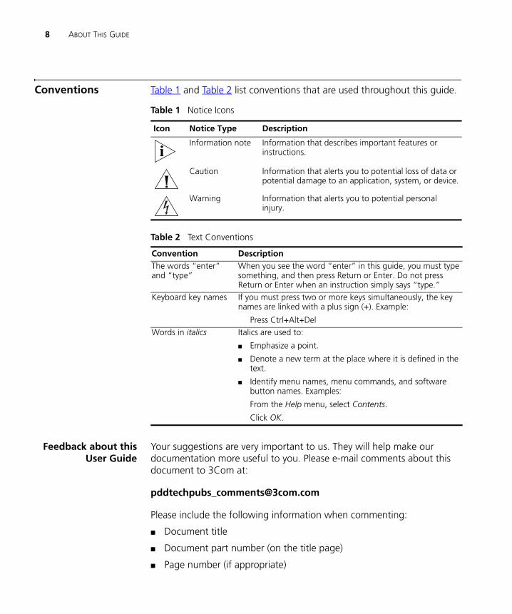
Conventions Table 1 and Table 2 list conventions that are used throughout this guide.
Feedback about thisUser Guide
Your suggestions are very important to us. They will help make our documentation more useful to you. Please e-mail comments about this document to 3Com at:
Please include the following information when commenting:
■ Document title
■ Document part number (on the title page)
■ Page number (if appropriate)
Table 1 Notice Icons
Icon Notice Type Description
Information note Information that describes important features or instructions.
Caution Information that alerts you to potential loss of data or potential damage to an application, system, or device.
Warning Information that alerts you to potential personal injury.
Table 2 Text Conventions
Convention DescriptionThe words “enter” and “type”
When you see the word “enter” in this guide, you must type something, and then press Return or Enter. Do not press Return or Enter when an instruction simply says “type.”
Keyboard key names If you must press two or more keys simultaneously, the key names are linked with a plus sign (+). Example:
Press Ctrl+Alt+Del Words in italics Italics are used to:
■ Emphasize a point.
■ Denote a new term at the place where it is defined in the text.
■ Identify menu names, menu commands, and software button names. Examples:
From the Help menu, select Contents.
Click OK.
Conventions 9
Example:
■ OfficeConnect Cable/DSL Gateway and Wireless Cable/DSL Gateway User Guide
■ Part Number DUA0085-5AAA04
■ Page 24
Do not use this e-mail address for technical support questions. For information about contacting Technical Support, please refer to the Support and Safety Information sheet.
RelatedDocumentation
In addition to this guide, each Gateway document set includes one Installation Guide. This guide contains the instructions you need to install and configure your Gateway.
Product Registration You can now register your Gateway on the 3Com web site and receive up-to-date information on your product:
http://support.3com.com/registration/frontpg.pl

10 ABOUT THIS GUIDE
1
INTRODUCING THE GATEWAYWelcome to the world of networking with 3Com®. In the modern business environment, communication and sharing information is crucial. Computer networks have proved to be one of the fastest modes of communication but, until recently, only large businesses could afford the networking advantage. The OfficeConnect® product range from 3Com has changed all this, bringing networks to the small office.
The products that compose the OfficeConnect range give you, the small office user, the same power, flexibility, and protection that has been available only to large corporations. Now, you can network the computers in your office, connect them all to a single Internet outlet, and harness the combined power of all of your computers.
OfficeConnect Cable/DSL Gateway and Wireless Cable/DSL Gateway
The OfficeConnect Cable/DSL Gateway and the OfficeConnect Wireless Cable/DSL Gateway are designed to provide a cost-effective means of sharing a single broadband Internet connection amongst several wired and wireless computers. The Gateway also provides protection in the form of an electronic “firewall” preventing anyone outside of your network from seeing your files or damaging your computers.
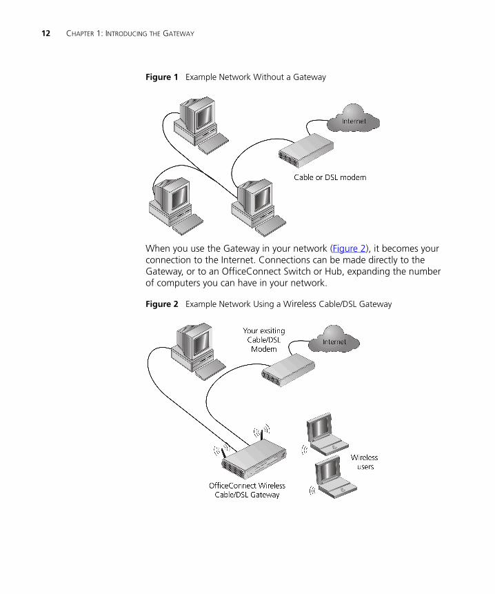
As you can see in the example in Figure 1, without a Gateway only one computer is connected to the Internet. This computer must always be powered on for the other computers on the network to access the Internet.
12 CHAPTER 1: INTRODUCING THE GATEWAY
Figure 1 Example Network Without a Gateway
When you use the Gateway in your network (Figure 2), it becomes your connection to the Internet. Connections can be made directly to the Gateway, or to an OfficeConnect Switch or Hub, expanding the number of computers you can have in your network.
Figure 2 Example Network Using a Wireless Cable/DSL Gateway
Gateway Advantages 13
Gateway Advantages
The advantages of the Gateway include:
■ Shared Internet connection for wired computers. The Wireless Cable/DSL Gateway also provides shared internet connection to wireless computers
■ No need for a dedicated, “always on” computer serving as your Internet connection
■ Cross-platform operation for compatibility with Windows, Unix and Macintosh computers
■ Easy-to-use, Web-based setup and configuration
■ Provides centralization of all network address settings (DHCP)
■ Acts as a Virtual server to enable remote access to Web, FTP, and other services on your network
■ Security - Firewall protection against Internet hacker attacks and encryption to protect wireless network traffic
Package Contents The Gateway kit includes the following items:
■ One OfficeConnect Cable/DSL Gateway or OfficeConnect Wireless Cable/DSL Gateway
■ One power adapter for use with the Gateway
■ Four rubber feet
■ One Ethernet cable
■ One CD-ROM containing the Gateway Discovery program and this User Guide
■ Installation Guide
■ One Support and Safety Information Sheet
■ One Warranty Flyer
If any of these items are missing or damaged, please contact your retailer.
14 CHAPTER 1: INTRODUCING THE GATEWAY
Minimum System and Component Requirements
Your Gateway requires that the computer(s) and components in your network be configured with at least the following:
■ A computer with an operating system that supports TCP/IP networking protocols (for example Windows 95/98/NT/Me/2000/XP, Unix, Mac OS 8.5 or higher).
■ An Ethernet 10Mbps or 10/100 Mbps NIC for each computer to be connected to the four-port switch on your Gateway.
■ An 802.11b wireless NIC (if you are using an OfficeConnect Wireless Cable/DSL Gateway).
■ A cable modem or DSL modem with an Ethernet port (RJ-45 connector).
■ An active Internet access account.
■ A Web browser program that supports JavaScript, such as Netscape 4.0 or higher or Internet Explorer 5.0 or higher.
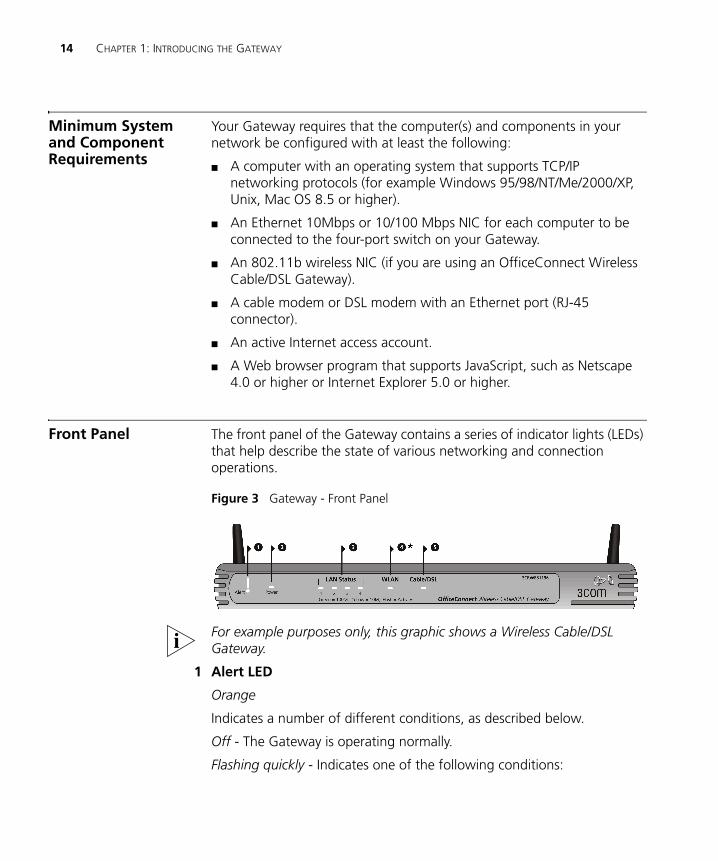
Front Panel The front panel of the Gateway contains a series of indicator lights (LEDs) that help describe the state of various networking and connection operations.
Figure 3 Gateway - Front Panel
For example purposes only, this graphic shows a Wireless Cable/DSL Gateway.
1 Alert LED
Orange
Indicates a number of different conditions, as described below.
Off - The Gateway is operating normally.
Flashing quickly - Indicates one of the following conditions:
Front Panel 15
■ The Gateway has just been started up and is running a self-test routine, or
■ The administrator has invoked the Reset to Factory Defaults command, or
■ The system software is in the process of being upgraded
In each of these cases, wait until the Gateway has completed the current operation and the alert LED is Off.
Flashing slowly - The Gateway has completed the Reset to Factory Defaults process, and is waiting for you to reset the unit. To do this, remove power, wait 10 seconds and then re-apply power. The Gateway will then enter the start-up sequence and resume normal operation.
If you have used a cable to reset the unit to Factory Defaults, follow steps 5 to 7 in “Forgotten Password and Reset to Factory Defaults” on page 76.
On for 2 seconds, and then off - The Gateway has detected and prevented a hacker from attacking your network from the Internet.
Continuously on - A fault has been detected with your Gateway during the start-up process. Refer to Chapter 6 “Troubleshooting”.
2 Power LED
Green
Indicates that the Gateway is powered on.
3 Four LAN Status LEDs
Green (100Mbps link) / yellow (10Mbps link)
If the LED is on, the link between the port and the next piece of network equipment is OK. If the LED is flashing, the link is OK and data is being transmitted or received. If the LED is off, nothing is connected, the connected device is switched off, or there is a problem with the connection (refer to Chapter 6 “Troubleshooting”). The port will automatically adjust to the correct speed and duplex.
16 CHAPTER 1: INTRODUCING THE GATEWAY
4 Wireless LAN (WLAN) Status LED
*Available on the OfficeConnect Wireless Cable/DSL Gateway only
Yellow
If the LED is on it indicates that wireless networking is enabled. If the LED is flashing, data is being transmitted or received. If the LED is off, the Wireless LAN has been disabled in the Gateway, or there is a problem. Refer to Chapter 6 “Troubleshooting”.
5 Cable/DSL Status LED
Green (100Mbps link) / yellow (10Mbps link)
If the LED is on, the link between the Gateway and the cable or DSL modem is OK. If the LED is flashing, the link is OK and data is being transmitted or received. If the LED is off, nothing is connected, the modem is switched off or there is a problem (refer to Chapter 6 “Troubleshooting”).
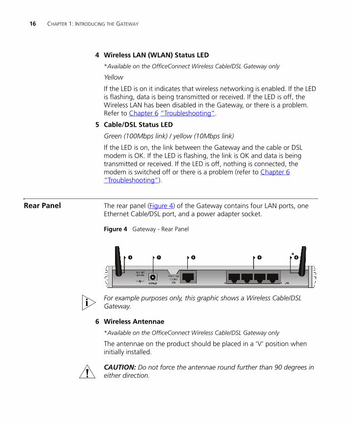
Rear Panel The rear panel (Figure 4) of the Gateway contains four LAN ports, one Ethernet Cable/DSL port, and a power adapter socket.
Figure 4 Gateway - Rear Panel
For example purposes only, this graphic shows a Wireless Cable/DSL Gateway.
6 Wireless Antennae
*Available on the OfficeConnect Wireless Cable/DSL Gateway only
The antennae on the product should be placed in a ‘V’ position when initially installed.
CAUTION: Do not force the antennae round further than 90 degrees in either direction.
Rear Panel 17
7 Power Adapter Socket
Only use the power adapter supplied with this Gateway. Do not use any other adapter.
8 Ethernet Cable/DSL port
Use the supplied patch cable to connect the Gateway to the Ethernet port on your cable or DSL modem. The port will automatically adjust to the correct speed and duplex.
9 Four 10/100 LAN ports
Using suitable RJ-45 cable, you can connect your Gateway to a computer, or to any other piece of equipment that has an Ethernet connection (for example, a hub or a switch). The LAN ports are configured as MDIX, for connection to a computer with a straight through RJ-45 cable.

18 CHAPTER 1: INTRODUCING THE GATEWAY
2
HARDWARE INSTALLATIONIntroduction This chapter will guide you through a basic installation of the Gateway, including:
■ Connecting the Gateway to the Internet.
■ Connecting the Gateway to your network.
■ Setting up your computers for networking with the Gateway.
Safety Information
WARNING: Please read the “Safety Information” section in Appendix D before you start.
VORSICHT: Bitte lesen Sie den Abschnitt “Wichtige Sicherheitshinweise” sorgfältig durch, bevor Sie das Gerät einschalten.
AVERTISSEMENT: Veuillez lire attentivement la section “Consignes importantes de sécurité” avant de mettre en route.
Positioning the Gateway
You should place the Gateway in a location that:
■ is conveniently located for connection to the cable or DSL modem that will be used to connect to the Internet.
■ allows convenient connection to the computers that will be connected to the four LAN ports on the rear panel, if desired.
■ allows easy viewing of the front panel LED indicator lights, and access to the rear panel connectors, if necessary.
■ (Wireless Cable/DSL Gateway only) is centrally located to the wireless computers that will connect to the Gateway. A suitable location might be on top of a high shelf or similar furniture to optimise wireless
20 CHAPTER 2: HARDWARE INSTALLATION
connections to computers in both horizontal and vertical directions, allowing wider coverage.
When positioning your Gateway, ensure:
■ It is out of direct sunlight and away from sources of heat.
■ Cabling is away from power lines, fluorescent lighting fixtures, and sources of electrical noise such as radios, transmitters and broadband amplifiers.
■ Water or moisture cannot enter the case of the unit.
■ Air flow around the unit and through the vents in the side of the case is not restricted. 3Com recommends you provide a minimum of 25 mm (1 in.) clearance.
Using the RubberFeet
Use the four self-adhesive rubber feet to prevent your Gateway from moving around on your desk or when stacking with other flat top OfficeConnect units. Only stick the feet to the marked areas at each corner of the underside of your Gateway.
Wall Mounting There are two slots on the underside of the Gateway that can be used for wall mounting.
When wall mounting the unit, ensure that it is within reach of the power outlet.
You will need two suitable screws to wall mount the unit. To do this:
1 Ensure that the wall you use is smooth, flat, dry and sturdy and make two screw holes which are 150 mm (5.9 in.) apart.
2 Fix the screws into the wall, leaving their heads 3 mm (0.12 in.) clear of the wall surface.
3 Remove any connections to the unit and locate it over the screw heads. When in line, gently push the unit on to the wall and move it downwards to secure.
When making connections, be careful not to push the unit up and off the wall.
Before you Install your Gateway 21
CAUTION: Only wall mount single units, do not wall mount stacked units.
Before you Install your Gateway
Before you install and configure your Gateway, you need the following additional information. If you do not have this information, contact your Internet Service Provider (ISP). Space is provided below for you to record this information.
If you have a DSL connection and your ISP allocates IP information dynamically over PPPoE, you need a User Name and Password:
PPPoE User Name : ______________________
PPPoE Password : ______________________
PPPoE Service Name : ______________________
If you have a DSL connection and your ISP allocates IP information dynamically over PPTP, you need a User Name and Password:
PPTP User Name : ______________________
PPTP Password : ______________________
PPTP Server Address : ____.____.____.____
You only need a PPPoE Service Name or a PPTP Server Address if your ISP requires one. Do not enter anything if your ISP does not require this information.
If your ISP allocates fixed or static IP information, you need the following information:
IP Address : ____.____.____.____
Subnet Mask : ____.____.____.____
Default Gateway address : ____.____.____.____
DNS address : ____.____.____.____
22 CHAPTER 2: HARDWARE INSTALLATION
If your ISP allocates IP information dynamically over a protocol other than PPPoE, you do not need any further information. This configuration is typical of cable connections.
Powering Up the Gateway
To power up the Gateway:
1 Plug the power adapter into the power adapter socket located on the back panel of the Gateway.
2 Plug the power adapter into a standard electrical wall socket.
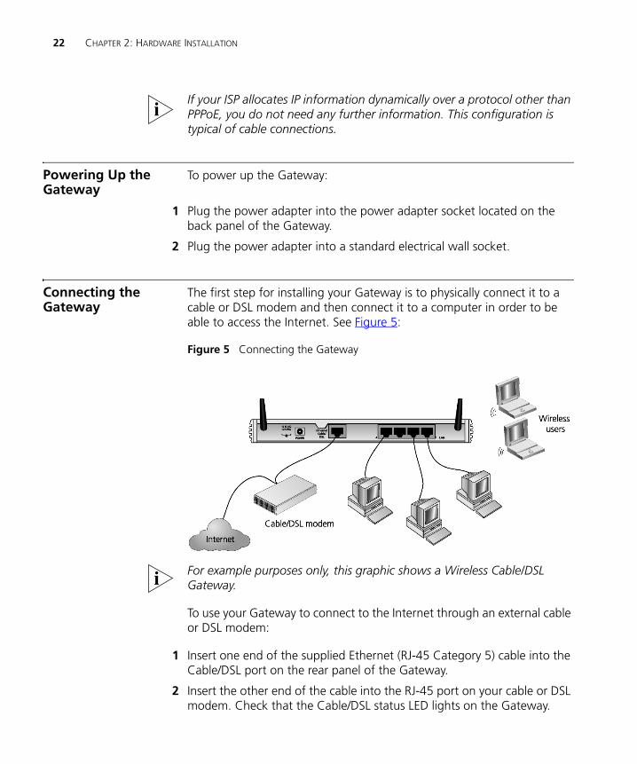
Connecting the Gateway
The first step for installing your Gateway is to physically connect it to a cable or DSL modem and then connect it to a computer in order to be able to access the Internet. See Figure 5:
Figure 5 Connecting the Gateway
For example purposes only, this graphic shows a Wireless Cable/DSL Gateway.
To use your Gateway to connect to the Internet through an external cable or DSL modem:
1 Insert one end of the supplied Ethernet (RJ-45 Category 5) cable into the Cable/DSL port on the rear panel of the Gateway.
2 Insert the other end of the cable into the RJ-45 port on your cable or DSL modem. Check that the Cable/DSL status LED lights on the Gateway.
Connecting the Gateway 23
3 Connect the cable or DSL modem to the Internet.
4 Connect your computer to one of the four LAN ports on the Gateway using a twisted pair cable. Check that the corresponding LAN status LED on the Gateway lights.
You have now completed the hardware installation of your Gateway. Next you need to set up your computers so that they can make use of the Gateway to communicate with the Internet.
3Com recommends that you perform the initial Gateway configuration from a computer that is directly connected to one of the LAN ports.
Wireless Only If you configure the Gateway from a wireless computer, note that you may lose contact with the Gateway if you change the wireless configuration.
To communicate with the Wireless Cable/DSL Gateway, your wireless NIC should be set as follows:
■ WEP encryption - none
■ Service Area Name/SSID - 3Com
■ Channel - 11

24 CHAPTER 2: HARDWARE INSTALLATION
3 SETTING UP YOUR COMPUTERS
The Gateway has the ability to dynamically allocate network addresses to the computers on your network, using DHCP. However, your computers need to be configured correctly for this to take place. To change the configuration of your computers to allow this, follow the instructions in this chapter. If your computers are configured with fixed or static addresses and you do not wish to change this, then you should use the Discovery program on the Gateway CD-ROM to detect and configure your Gateway. Refer to Appendix A for information on using the Discovery program.
Obtaining an IP Address Automatically
Windows 2000 If you are using a Windows 2000-based computer, use the following procedure to change your TCP/IP settings:
1 From the Windows Start Menu, select Settings > Control Panel.
2 Double click on Network and Dial-Up Connections.
3 Double click on Local Area Connection.
4 Click on Properties.
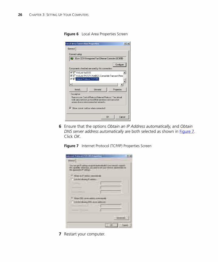
5 A screen similar to Figure 6 should be displayed. Select Internet Protocol TCP/IP and click on Properties.
26 CHAPTER 3: SETTING UP YOUR COMPUTERS
Figure 6 Local Area Properties Screen
6 Ensure that the options Obtain an IP Address automatically, and Obtain DNS server address automatically are both selected as shown in Figure 7. Click OK.
Figure 7 Internet Protocol (TCP/IP) Properties Screen
7 Restart your computer.
Obtaining an IP Address Automatically 27
Windows XP
1 From the Windows Start menu, select Control Panel.
2 Click on Network and Internet Connections.
3 Click on the Network Connections icon.
4 Double click on LAN or High Speed Connection icon. A screen titled Local Area Connection Status will appear.
5 Select Internet Protocol TCP/IP and click on Properties.
6 Ensure that the options Obtain an IP Address automatically, and Obtain DNS servers automatically are both selected. Click OK.
7 Restart your computer.
Windows 95/98/ME
1 From the Windows Start Menu, select Settings > Control Panel.
2 Double click on Network. Select the TCP/IP item for your network card and click on Properties.
3 In the TCP/IP dialog, select the IP Address tab, and ensure that Obtain IP address automatically is selected. Click OK.
Macintosh If you are using a Macintosh computer, use the following procedure to change your TCP/IP settings:
1 From the desktop, select Apple Menu, Control Panels, and TCP/IP.
2 In the TCP/IP control panel, set Connect Via: to “Ethernet”.
3 In the TCP/IP control panel, set Configure: to “Using DHCP Server.”
4 Close the TCP/IP dialog box, and save your changes.
5 Restart your computer.
28 CHAPTER 3: SETTING UP YOUR COMPUTERS
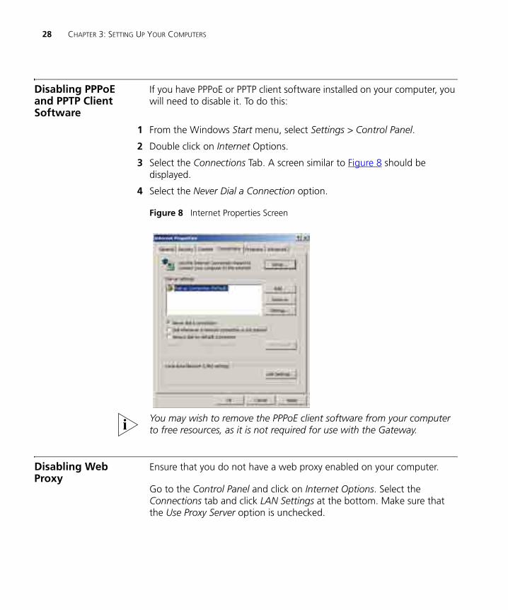
Disabling PPPoE and PPTP Client Software
If you have PPPoE or PPTP client software installed on your computer, you will need to disable it. To do this:
1 From the Windows Start menu, select Settings > Control Panel.
2 Double click on Internet Options.
3 Select the Connections Tab. A screen similar to Figure 8 should be displayed.
4 Select the Never Dial a Connection option.
Figure 8 Internet Properties Screen
You may wish to remove the PPPoE client software from your computer to free resources, as it is not required for use with the Gateway.
Disabling Web Proxy
Ensure that you do not have a web proxy enabled on your computer.
Go to the Control Panel and click on Internet Options. Select the Connections tab and click LAN Settings at the bottom. Make sure that the Use Proxy Server option is unchecked.
4
RUNNING THE SETUP WIZARDAccessing the Wizard
The Gateway setup program is Web-based, which means that it is accessed through your Web browser (Netscape Navigator or Internet Explorer).
To use the Setup Wizard:
1 Ensure that you have at least one computer connected to the Gateway. Refer to Chapter 2 for details on how to do this.
2 Launch your Web browser on the computer.
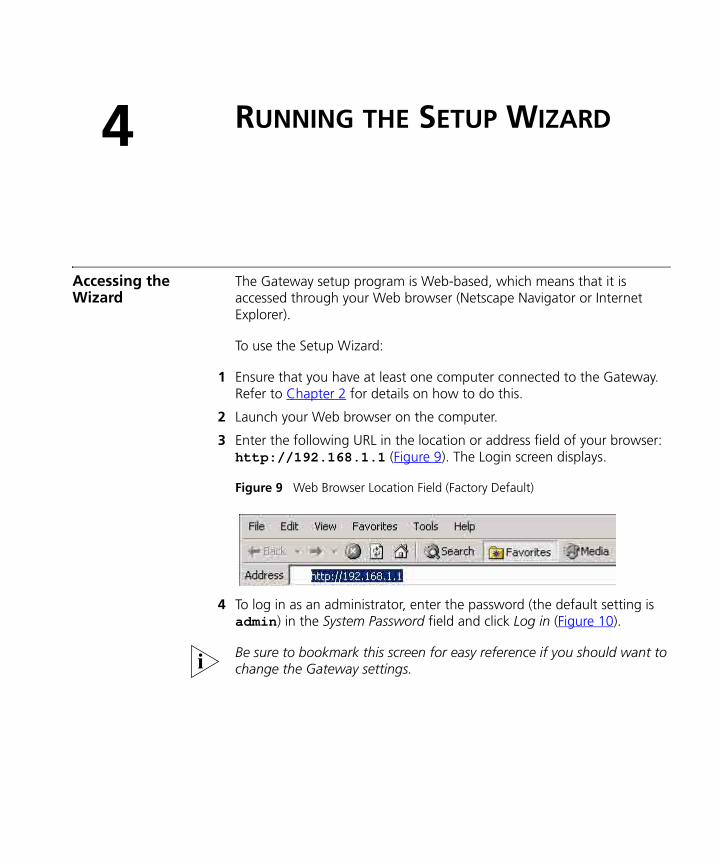
3 Enter the following URL in the location or address field of your browser: http://192.168.1.1 (Figure 9). The Login screen displays.
Figure 9 Web Browser Location Field (Factory Default)
4 To log in as an administrator, enter the password (the default setting is admin) in the System Password field and click Log in (Figure 10).
Be sure to bookmark this screen for easy reference if you should want to change the Gateway settings.
30 CHAPTER 4: RUNNING THE SETUP WIZARD
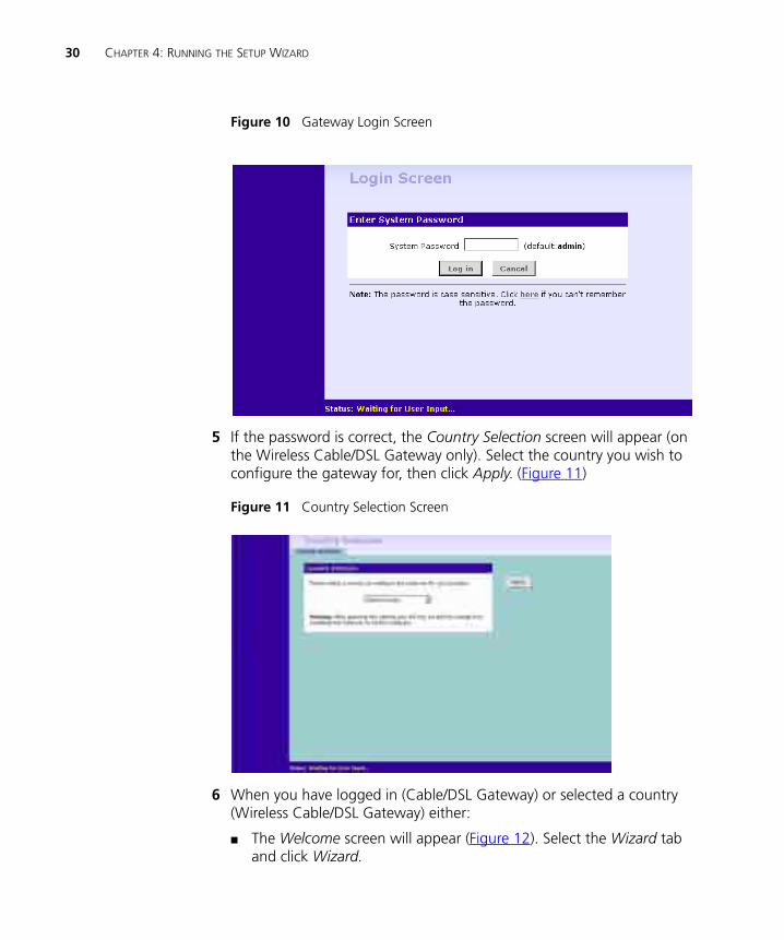
Figure 10 Gateway Login Screen
5 If the password is correct, the Country Selection screen will appear (on the Wireless Cable/DSL Gateway only). Select the country you wish to configure the gateway for, then click Apply. (Figure 11)
Figure 11 Country Selection Screen
6 When you have logged in (Cable/DSL Gateway) or selected a country (Wireless Cable/DSL Gateway) either:
■ The Welcome screen will appear (Figure 12). Select the Wizard tab and click Wizard.
Accessing the Wizard 31
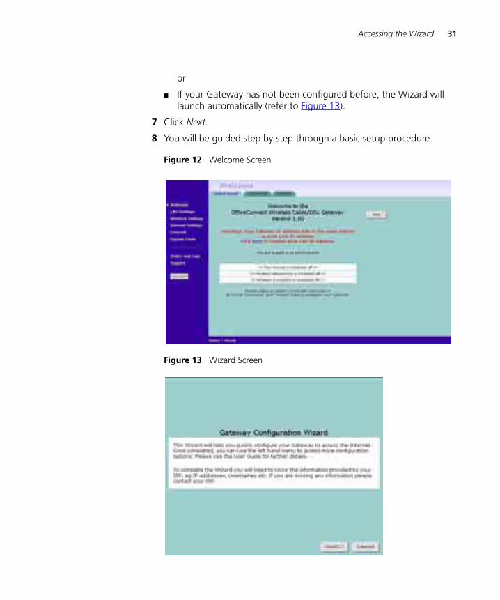
or
■ If your Gateway has not been configured before, the Wizard will launch automatically (refer to Figure 13).
7 Click Next.
8 You will be guided step by step through a basic setup procedure.
Figure 12 Welcome Screen
Figure 13 Wizard Screen
32 CHAPTER 4: RUNNING THE SETUP WIZARD
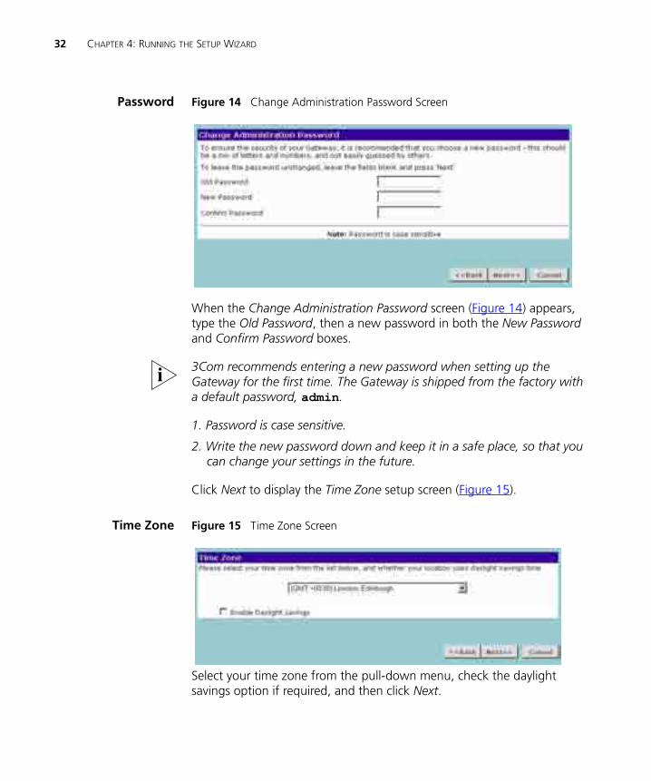
Password Figure 14 Change Administration Password Screen
When the Change Administration Password screen (Figure 14) appears, type the Old Password, then a new password in both the New Password and Confirm Password boxes.
3Com recommends entering a new password when setting up the Gateway for the first time. The Gateway is shipped from the factory with a default password, admin.
1. Password is case sensitive.
2. Write the new password down and keep it in a safe place, so that you can change your settings in the future.
Click Next to display the Time Zone setup screen (Figure 15).
Time Zone Figure 15 Time Zone Screen
Select your time zone from the pull-down menu, check the daylight savings option if required, and then click Next.
Accessing the Wizard 33
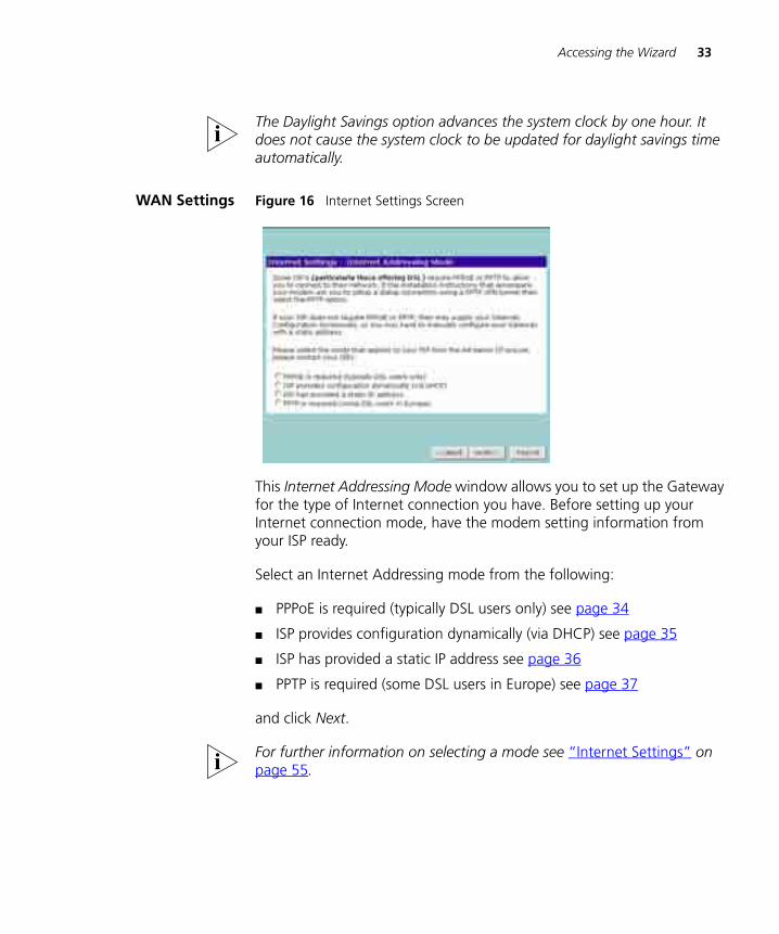
The Daylight Savings option advances the system clock by one hour. It does not cause the system clock to be updated for daylight savings time automatically.
WAN Settings Figure 16 Internet Settings Screen
This Internet Addressing Mode window allows you to set up the Gateway for the type of Internet connection you have. Before setting up your Internet connection mode, have the modem setting information from your ISP ready.
Select an Internet Addressing mode from the following:
■ PPPoE is required (typically DSL users only) see page 34
■ ISP provides configuration dynamically (via DHCP) see page 35
■ ISP has provided a static IP address see page 36
■ PPTP is required (some DSL users in Europe) see page 37
and click Next.
For further information on selecting a mode see “Internet Settings” on page 55.
34 CHAPTER 4: RUNNING THE SETUP WIZARD
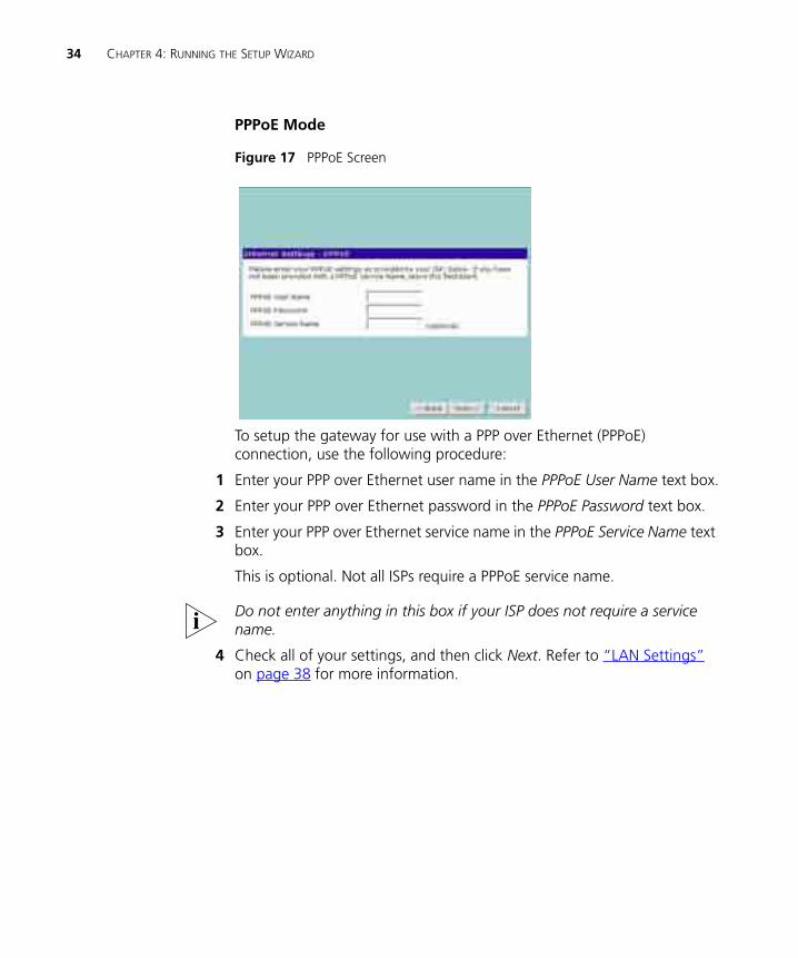
PPPoE Mode
Figure 17 PPPoE Screen
To setup the gateway for use with a PPP over Ethernet (PPPoE) connection, use the following procedure:
1 Enter your PPP over Ethernet user name in the PPPoE User Name text box.
2 Enter your PPP over Ethernet password in the PPPoE Password text box.
3 Enter your PPP over Ethernet service name in the PPPoE Service Name text box.
This is optional. Not all ISPs require a PPPoE service name.
Do not enter anything in this box if your ISP does not require a service name.
4 Check all of your settings, and then click Next. Refer to “LAN Settings” on page 38 for more information.
Accessing the Wizard 35
Dynamic IP Address Mode
To setup the Gateway for use with a dynamic IP address connection:
1 Select the ISP provides configuration dynamically (via DHCP) and then click Next. See Figure 16.
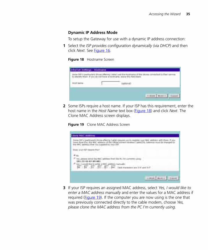
Figure 18 Hostname Screen
2 Some ISPs require a host name. If your ISP has this requirement, enter the host name in the Host Name text box (Figure 18) and click Next. The Clone MAC Address screen displays.
Figure 19 Clone MAC Address Screen
3 If your ISP requires an assigned MAC address, select Yes, I would like to enter a MAC address manually and enter the values for a MAC address if required (Figure 19). If the computer you are now using is the one that was previously connected directly to the cable modem, choose Yes, please clone the MAC address from the PC I’m currently using.
36 CHAPTER 4: RUNNING THE SETUP WIZARD
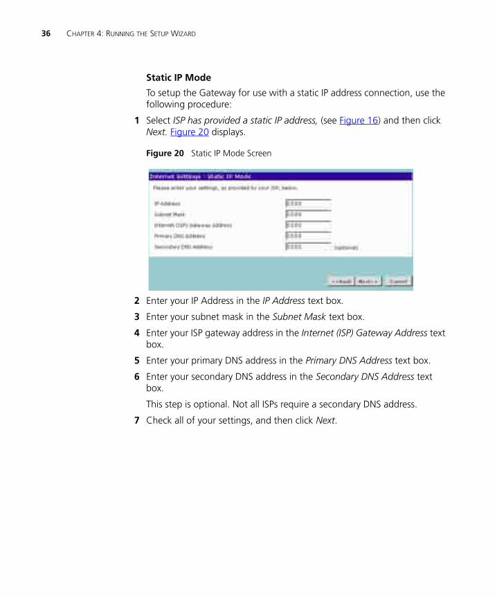
Static IP Mode
To setup the Gateway for use with a static IP address connection, use the following procedure:
1 Select ISP has provided a static IP address, (see Figure 16) and then click Next. Figure 20 displays.
Figure 20 Static IP Mode Screen
2 Enter your IP Address in the IP Address text box.
3 Enter your subnet mask in the Subnet Mask text box.
4 Enter your ISP gateway address in the Internet (ISP) Gateway Address text box.
5 Enter your primary DNS address in the Primary DNS Address text box.
6 Enter your secondary DNS address in the Secondary DNS Address text box.
This step is optional. Not all ISPs require a secondary DNS address.
7 Check all of your settings, and then click Next.
Accessing the Wizard 37
PPTP Mode
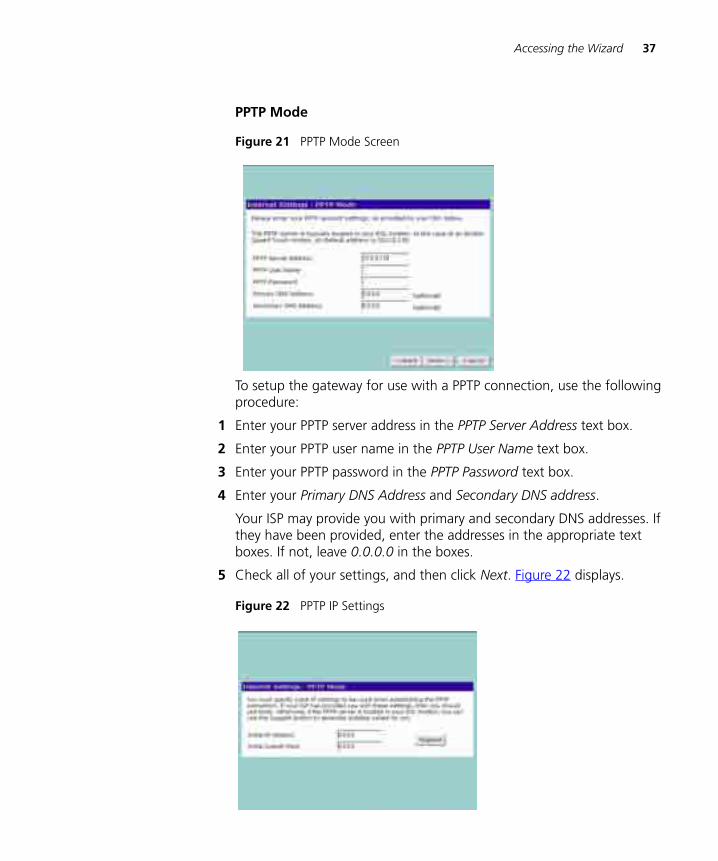
Figure 21 PPTP Mode Screen
To setup the gateway for use with a PPTP connection, use the following procedure:
1 Enter your PPTP server address in the PPTP Server Address text box.
2 Enter your PPTP user name in the PPTP User Name text box.
3 Enter your PPTP password in the PPTP Password text box.
4 Enter your Primary DNS Address and Secondary DNS address.
Your ISP may provide you with primary and secondary DNS addresses. If they have been provided, enter the addresses in the appropriate text boxes. If not, leave 0.0.0.0 in the boxes.
5 Check all of your settings, and then click Next. Figure 22 displays.
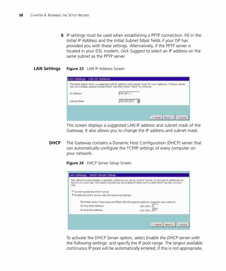
Figure 22 PPTP IP Settings
38 CHAPTER 4: RUNNING THE SETUP WIZARD
6 IP settings must be used when establishing a PPTP connection. Fill in the Initial IP Address and the Initial Subnet Mask fields if your ISP has provided you with these settings. Alternatively, if the PPTP server is located in your DSL modem, click Suggest to select an IP address on the same subnet as the PPTP server.
LAN Settings Figure 23 LAN IP Address Screen
This screen displays a suggested LAN IP address and subnet mask of the Gateway. It also allows you to change the IP address and subnet mask.
DHCP The Gateway contains a Dynamic Host Configuration (DHCP) server that can automatically configure the TCP/IP settings of every computer on your network.
Figure 24 DHCP Server Setup Screen
To activate the DHCP Server option, select Enable the DHCP server with the following settings: and specify the IP pool range. The largest available continuous IP pool will be automatically entered; if this is not appropriate,
Accessing the Wizard 39
make your required changes. To disable DHCP, select Do not enable the DHCP server. Click Next when you have finished.
If you have a Cable/DSL Gateway, your Gateway is now configured and ready for use. See Chapter 5 for a detailed description of the Gateway configuration screens. If you have a Wireless Cable/DSL Gateway refer to “Wireless Settings” below.
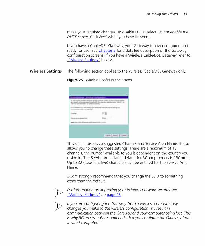
Wireless Settings The following section applies to the Wireless Cable/DSL Gateway only.
Figure 25 Wireless Configuration Screen
This screen displays a suggested Channel and Service Area Name. It also allows you to change these settings. There are a maximum of 13 channels, the number available to you is dependent on the country you reside in. The Service Area Name default for 3Com products is "3Com". Up to 32 (case sensitive) characters can be entered for the Service Area Name.
3Com strongly recommends that you change the SSID to something other than the default.
For information on improving your Wireless network security see “Wireless Settings” on page 46.
If you are configuring the Gateway from a wireless computer any changes you make to the wireless configuration will result in communication between the Gateway and your computer being lost. This is why 3Com strongly recommends that you configure the Gateway from a wired computer.
40 CHAPTER 4: RUNNING THE SETUP WIZARD
It is very important that you set up your wireless clients to use the same Service Area Name or SSID as the one you use on this screen. If your clients use a different Service Area Name then they will not be able to communicate with the Gateway.
The choice of channel is less important as Clients will generally search all of the available channels. You should however make a note of the channel you select as this may be useful if you experience problems with your clients.
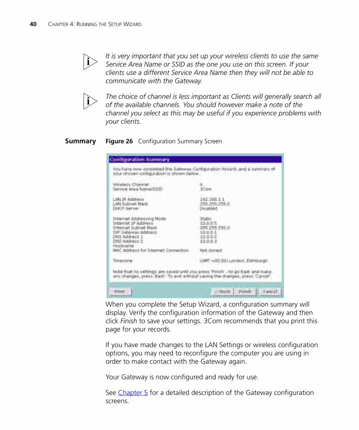
Summary Figure 26 Configuration Summary Screen
When you complete the Setup Wizard, a configuration summary will display. Verify the configuration information of the Gateway and then click Finish to save your settings. 3Com recommends that you print this page for your records.
If you have made changes to the LAN Settings or wireless configuration options, you may need to reconfigure the computer you are using in order to make contact with the Gateway again.
Your Gateway is now configured and ready for use.
See Chapter 5 for a detailed description of the Gateway configuration screens.
5
GATEWAY CONFIGURATIONNavigating Through the Gateway Configuration Pages
This chapter describes all the screens available through the Gateway configuration pages, and is provided as a reference. To get to the configuration pages, browse to the Gateway by entering the URL in the location bar of your browser. The default URL is http://192.168.1.1 but if you changed the Gateway LAN IP address during initial configuration, use the new IP address instead. When you have browsed to the Gateway, log in using your system password (default admin).
Main Menu At the left side of all screens is a main menu, as shown in Figure 27 on page 42. When you click on a topic from the main menu, that page will appear in the main part of the screen.
■ Welcome - displays the firmware version of the Gateway, allows you to change your password, and launch the Wizard
■ LAN Settings - allows you to configure IP address and subnet mask information, setup DHCP server parameters, and display the DHCP client list.
■ Wireless Settings (Wireless Cable/DSL Gateway only) - enables /disables access from wireless computers, and provides facilities for improving the security of the wireless network.
■ Internet Settings - sets up Internet addressing modes such as PPPoE and PPTP connections, dynamic IP address allocation and static IP address settings
■ Firewall - allows configuration of the Gateway’s firewall features: Virtual Servers, Special Applications, PCs Privileges and security options
■ System Tools - allows the administrator to perform maintenance activities on the Gateway.
42 CHAPTER 5: GATEWAY CONFIGURATION
■ Status and Logs - displays the current status and activity logs of the Gateway.
■ Support - contains a comprehensive online help system
Option Tabs Each corresponding menu page may also provide sub-sections which are accessed through the use of tabs (see Figure 27 for example). To access a sub-section, simply click on the required tab.
Getting Help
On every screen, a Help button is available which provides access to the context-sensitive online help system. Click Help for further assistance and guidance relating to the current screen.
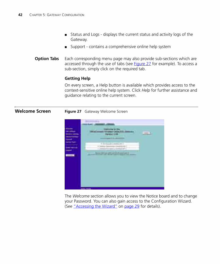
Welcome Screen Figure 27 Gateway Welcome Screen
The Welcome section allows you to view the Notice board and to change your Password. You can also gain access to the Configuration Wizard. (See “Accessing the Wizard” on page 29 for details).
Welcome Screen 43
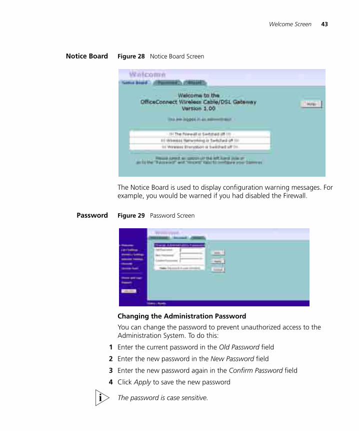
Notice Board Figure 28 Notice Board Screen
The Notice Board is used to display configuration warning messages. For example, you would be warned if you had disabled the Firewall.
Password Figure 29 Password Screen
Changing the Administration Password
You can change the password to prevent unauthorized access to the Administration System. To do this:
1 Enter the current password in the Old Password field
2 Enter the new password in the New Password field
3 Enter the new password again in the Confirm Password field
4 Click Apply to save the new password
The password is case sensitive.
44 CHAPTER 5: GATEWAY CONFIGURATION
If you have forgotten your password you need to reset the Gateway. See “Forgotten Password and Reset to Factory Defaults” on page 76
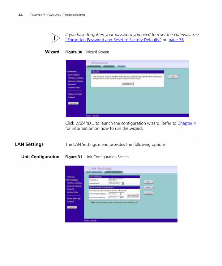
Wizard Figure 30 Wizard Screen
Click WIZARD... to launch the configuration wizard. Refer to Chapter 4 for information on how to run the wizard.
LAN Settings The LAN Settings menu provides the following options:
Unit Configuration Figure 31 Unit Configuration Screen
LAN Settings 45
The LAN Settings screen is used to specify the LAN IP address of your Gateway, and to configure the DHCP server.
1 Select Unit Configuration and then specify the Gateway IP Address and Subnet Mask in the LAN Settings field. The default IP address of the Gateway is 192.168.1.1.
2 If you want to use the Gateway as a DHCP Server, click in the Enable check box.
3 Clicking Auto Range will automatically choose the largest available range of addresses for your network.
4 Check all of your settings, and then click Apply.
The DHCP server will give out addresses to both wired and wireless clients.
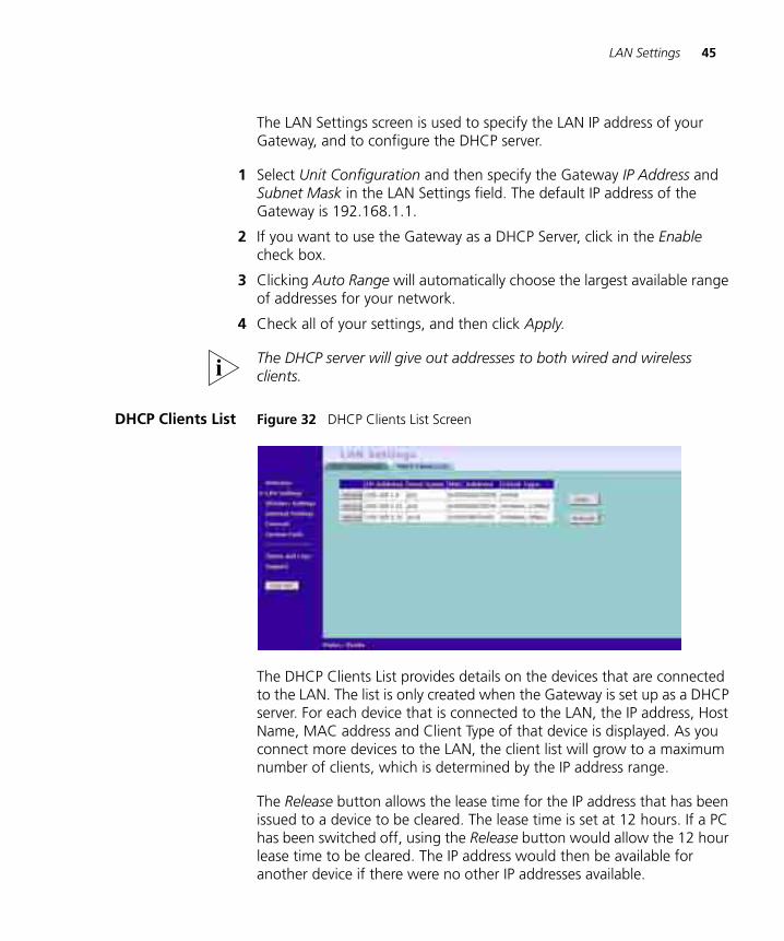
DHCP Clients List Figure 32 DHCP Clients List Screen
The DHCP Clients List provides details on the devices that are connected to the LAN. The list is only created when the Gateway is set up as a DHCP server. For each device that is connected to the LAN, the IP address, Host Name, MAC address and Client Type of that device is displayed. As you connect more devices to the LAN, the client list will grow to a maximum number of clients, which is determined by the IP address range.
The Release button allows the lease time for the IP address that has been issued to a device to be cleared. The lease time is set at 12 hours. If a PC has been switched off, using the Release button would allow the 12 hour lease time to be cleared. The IP address would then be available for another device if there were no other IP addresses available.
46 CHAPTER 5: GATEWAY CONFIGURATION
As the IP address is fixed to a MAC address, then each particular computer will normally be issued with the same IP address. The only time that a PC will get a different IP address is if the unit is reset to factory defaults or the DHCP server has run out of IP addresses.
Wireless Settings The following section applies to the Wireless Cable/DSL Gateway only.
To improve the security of your wireless network, 3Com recommends that you:
1. Change the SSID from its default value - see page 47
2. Enable Encryption - see page 48
3. Enable Connection Control - see page 50
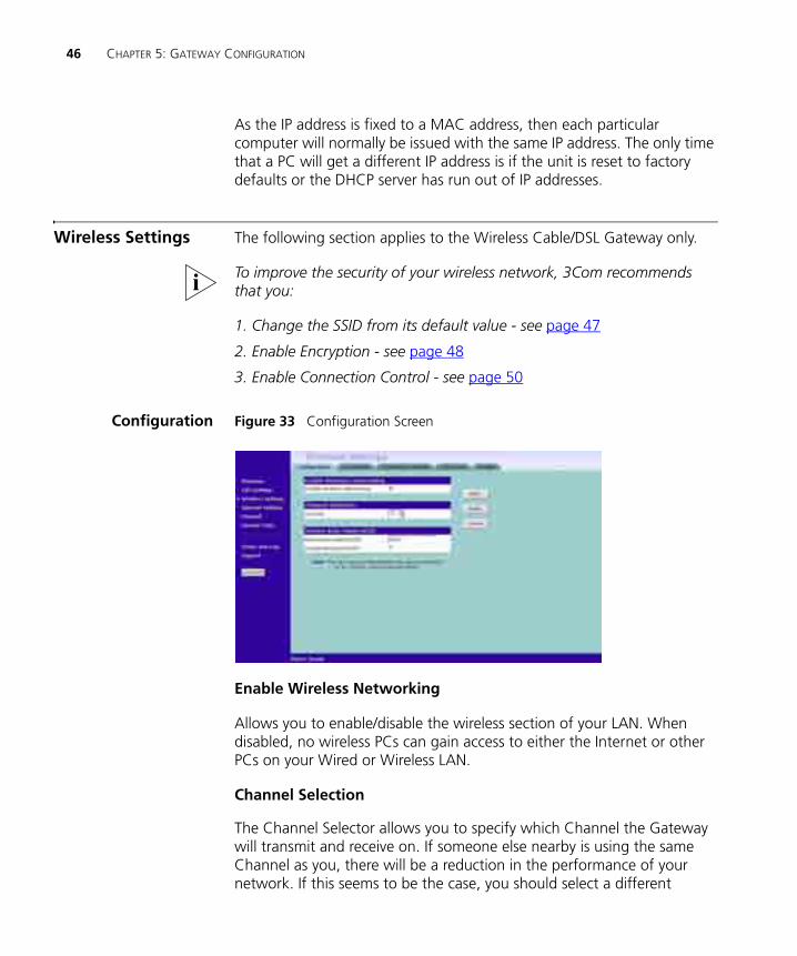
Configuration Figure 33 Configuration Screen
Enable Wireless Networking
Allows you to enable/disable the wireless section of your LAN. When disabled, no wireless PCs can gain access to either the Internet or other PCs on your Wired or Wireless LAN.
Channel Selection
The Channel Selector allows you to specify which Channel the Gateway will transmit and receive on. If someone else nearby is using the same Channel as you, there will be a reduction in the performance of your network. If this seems to be the case, you should select a different
Wireless Settings 47
channel number. Usually the Wireless computers will scan to find the correct channel, but if they don't you must configure them to use the same Channel number as the Gateway.
Valid channels are country dependent. See “Channels” on page 115 for a list of channels approved by each country.
Service Area Name/SSID
This allows you to name your Wireless network. The field will accept any alphanumeric string and has a maximum length of 32 characters. Your Wireless computers must be configured with exactly the same name or you will not establish a connection. The Service Area Name may also be referred to as "ESSID" depending on your networking vendor. By default the Gateway uses the name "3Com". 3Com recommends that you change the default name.
In order that your wireless computers can connect to the Gateway, you must:
■ Use Infrastructure Mode not Adhoc Mode.
■ Have the same Service Area Name as the Gateway.
■ Have the same Channel number as the Gateway.
■ Use the same encryption type and keys as the Gateway.
■ Ensure that the PC is included in the authorised Wireless PCs list if Connection Control is enabled. See page 50.
Disable Broadcast SSID
This feature can be used to improve the security of your wireless network. When the tickbox is checked, the Gateway will not broadcast the Service Area Name/SSID of your wireless network. This will prevent unauthorised clients from detecting your SSID and attempting to connect to your network.
If you have a wireless client that can detect all the available SSIDs in your area, your client will not list the Gateway SSID when this feature is enabled.
3Com recommends that you install your wireless network with this feature disabled and then enable it once you have set up the Gateway and wireless clients.

48 CHAPTER 5: GATEWAY CONFIGURATION
Encryption Figure 34 Encryption Screen
Wired Equivalent Privacy or WEP allows you to encrypt the traffic between your Wireless PC and the Gateway. It is important to remember that with WEP disabled anyone with a Wireless PC can eavesdrop on your network. 3Com recommends that you get the network working with WEP disabled first and then enable it as the last step. This will simplify setting up your network.
If you enable WEP on the Gateway, you must reconfigure your wireless PCs to use exactly the same Encryption Type and Keys otherwise the devices will not understand each other.
WEP is for securing data transmitted through wireless communications between the Gateway and it's wireless clients. Enabling WEP has no security effect on data transmitted through wired (Ethernet) connections or through your connections to the Internet.
Wireless Encryption Type
There are two levels of encryption available, 64 bit (sometimes referred to as 40 bit) and 128 bit. 128 bit will result in a higher level of security, but may cause a slight decrease in performance. Use the Wireless Encryption Type box to select the desired level.
Wireless Settings 49
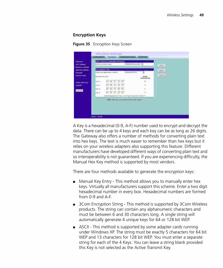
Encryption Keys
Figure 35 Encryption Keys Screen
A Key is a hexadecimal (0-9, A-F) number used to encrypt and decrypt the data. There can be up to 4 keys and each key can be as long as 26 digits. The Gateway also offers a number of methods for converting plain text into hex keys. The text is much easier to remember than hex keys but it relies on your wireless adapters also supporting this feature. Different manufacturers have developed different ways of converting plain text and so interoperability is not guaranteed. If you are experiencing difficulty, the Manual Hex Key method is supported by most vendors.
There are four methods available to generate the encryption keys:
■ Manual Key Entry - This method allows you to manually enter hex keys. Virtually all manufacturers support this scheme. Enter a two digit hexadecimal number in every box. Hexadecimal numbers are formed from 0-9 and A-F.
■ 3Com Encryption String - This method is supported by 3Com Wireless products. The string can contain any alphanumeric characters and must be between 6 and 30 characters long. A single string will automatically generate 4 unique keys for 64 or 128 bit WEP.
■ ASCII - This method is supported by some adapter cards running under Windows XP. The string must be exactly 5 characters for 64 bit WEP and 13 characters for 128 bit WEP. You must enter a separate string for each of the 4 Keys. You can leave a string blank provided this Key is not selected as the Active Transmit Key.
50 CHAPTER 5: GATEWAY CONFIGURATION
■ Passphrase - This is another common method and similar to the 3Com Encryption string. In 64 bit WEP, the passphrase will generate 4 different keys. However, in 128 bit WEP, this method only generates 1 key which is replicated for all 4 keys. The passphrase can be up to 31 characters long and may contain any alphanumeric characters.
Select from the drop down list the key generation method you wish to use. If you have other wireless products choose the scheme that is compatible with these, then enter the appropriate information.
If you encounter any difficulty when you enable WEP ensure that you check that each key on your wireless computer is exactly the same as each key on your Gateway. In other words, Key number 1 on the Wireless computer must have the same Hex number as Key number 1 on the Gateway, Key 2 on the Wireless computer must match Key 2 on the Gateway and so on.
The Active Transmit Key selects which of the 4 Keys the Gateway uses when it transmits. You can change the selected key periodically to increase the security of your network.
Some wireless adapters have only one key available on their WEP configuration page. If this is the case ensure it is the same as Key 1 on the Gateway and that it is selected as the active transmit key.
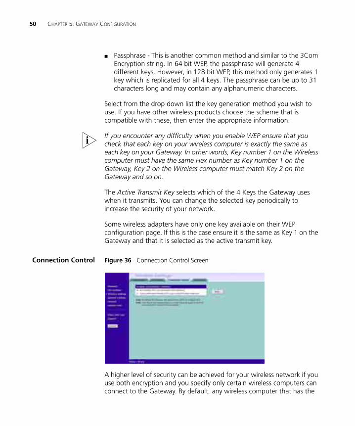
Connection Control Figure 36 Connection Control Screen
A higher level of security can be achieved for your wireless network if you use both encryption and you specify only certain wireless computers can connect to the Gateway. By default, any wireless computer that has the
Wireless Settings 51
same Service Area Name/SSID, channel and encryption settings as the Gateway can connect to it.
Select Only Authorised Wireless PCs can connect to the Gateway to enable and configure this feature.
If you enable this feature from a Wireless PC, it will automatically be added to the Authorised Wireless PC list.
Authorised Wireless PCs
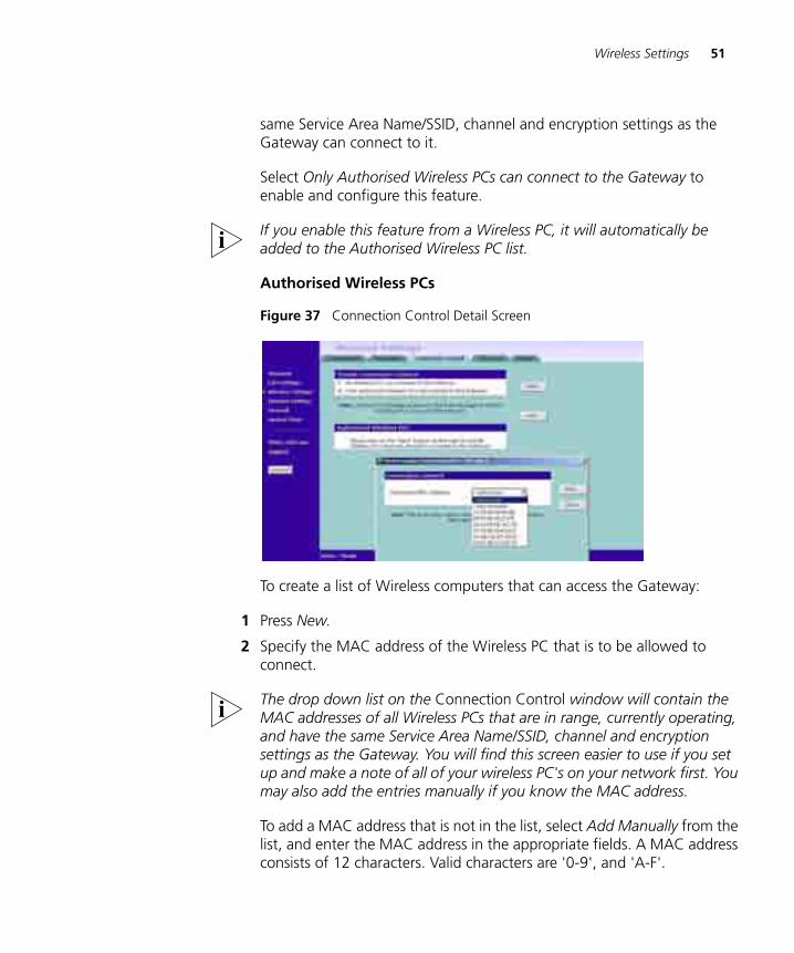
Figure 37 Connection Control Detail Screen
To create a list of Wireless computers that can access the Gateway:
1 Press New.
2 Specify the MAC address of the Wireless PC that is to be allowed to connect.
The drop down list on the Connection Control window will contain the MAC addresses of all Wireless PCs that are in range, currently operating, and have the same Service Area Name/SSID, channel and encryption settings as the Gateway. You will find this screen easier to use if you set up and make a note of all of your wireless PC's on your network first. You may also add the entries manually if you know the MAC address.
To add a MAC address that is not in the list, select Add Manually from the list, and enter the MAC address in the appropriate fields. A MAC address consists of 12 characters. Valid characters are '0-9', and 'A-F'.
52 CHAPTER 5: GATEWAY CONFIGURATION
3 Press Add.
Click Close to discard all changes.
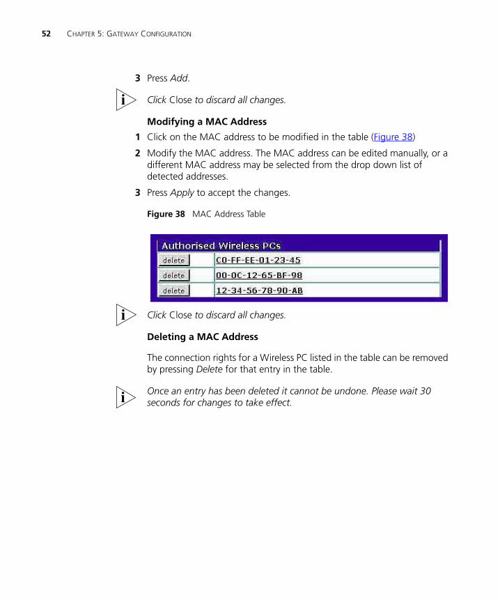
Modifying a MAC Address
1 Click on the MAC address to be modified in the table (Figure 38)
2 Modify the MAC address. The MAC address can be edited manually, or a different MAC address may be selected from the drop down list of detected addresses.
3 Press Apply to accept the changes.
Figure 38 MAC Address Table
Click Close to discard all changes.
Deleting a MAC Address
The connection rights for a Wireless PC listed in the table can be removed by pressing Delete for that entry in the table.
Once an entry has been deleted it cannot be undone. Please wait 30 seconds for changes to take effect.
Wireless Settings 53
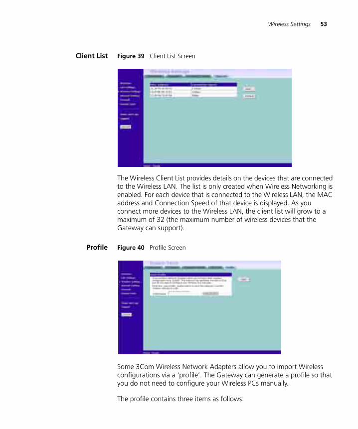
Client List Figure 39 Client List Screen
The Wireless Client List provides details on the devices that are connected to the Wireless LAN. The list is only created when Wireless Networking is enabled. For each device that is connected to the Wireless LAN, the MAC address and Connection Speed of that device is displayed. As you connect more devices to the Wireless LAN, the client list will grow to a maximum of 32 (the maximum number of wireless devices that the Gateway can support).
Profile Figure 40 Profile Screen
Some 3Com Wireless Network Adapters allow you to import Wireless configurations via a ‘profile’. The Gateway can generate a profile so that you do not need to configure your Wireless PCs manually.
The profile contains three items as follows:
54 CHAPTER 5: GATEWAY CONFIGURATION
■ Service Area Name/SSID of the Gateway
This is configured on the Configuration tab under the Wireless Settings option.
■ Encryption settings from the Gateway
This is configured on the Encryption tab under the Wireless Settings option.
■ Profile Name
This is used to identify the profile once it has been imported into the Wireless Network Adapter configuration software.
To set up a profile (once the Service Area Name/SSID and Encryption settings have been configured in the Gateway):
1 Enter a Profile Name (up to 25 alphanumeric characters) and then click Save Profile.
2 Your browser will then prompt you to enter a file name and folder location in which to save the profile. Once the profile has been saved it can be copied on to another PC and imported into the 3Com Wireless Network Adapter.
For instructions on how to import a profile, refer to the User Guide that accompanies your 3Com Wireless Network Adapter(s).
If, once the profile is imported, the Wireless Network Adapter cannot connect to the Gateway, check that:
■ the adapter is within range of the Gateway
if Connection Control has been enabled in the Gateway, the MAC address of the Wireless Network Adapter must be included in the list of authorised Wireless PCs.
Internet Settings 55
Internet Settings Before you can configure the Gateway, you need to know the IP information allocation method used by your ISP. There are four different ways that ISPs can allocate IP information, as described below:
1 Static IP Address (DSL or Cable)
The ISP provides the IP addressing information for you to enter manually. To configure the Gateway you will need to know the following:
■ IP Address
■ Subnet Mask
■ ISP Gateway
■ DNS address(es)
2 Dynamic IP Address (DSL or Cable)
Dynamic IP addressing (or DHCP) automatically assigns the Gateway IP information. This method is popular with Cable providers. This method is also used if your modem has a built in DHCP server.
3 PPPoE (DSL only)
If the installation instructions that accompany your modem ask you to install a PPPoE client on your PC, then select this option. To configure the Gateway you will need to know the following:
■ Username
■ Password
■ Service Name (if required by your ISP)
When you install the Gateway, you will not need to use the PPPoE software on your PC.
4 PPTP (DSL or Cable)
PPTP is only used by some European providers. If the installation instructions that accompany your modem ask you to setup a dialup connection using a PPTP VPN tunnel then select this option. To configure the Gateway you will need to know the following:
■ Username
■ Password
■ VPN Server address (usually your modem)
56 CHAPTER 5: GATEWAY CONFIGURATION
When you install the Gateway, you will not need to use the dialup VPN on your PC anymore.
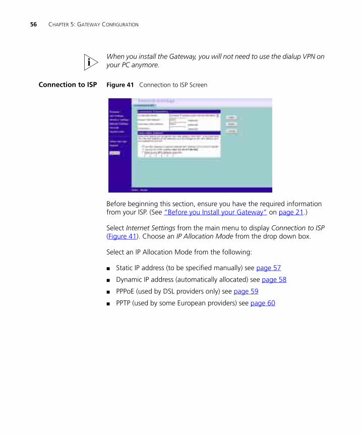
Connection to ISP Figure 41 Connection to ISP Screen
Before beginning this section, ensure you have the required information from your ISP. (See “Before you Install your Gateway” on page 21.)
Select Internet Settings from the main menu to display Connection to ISP (Figure 41). Choose an IP Allocation Mode from the drop down box.
Select an IP Allocation Mode from the following:
■ Static IP address (to be specified manually) see page 57
■ Dynamic IP address (automatically allocated) see page 58
■ PPPoE (used by DSL providers only) see page 59
■ PPTP (used by some European providers) see page 60
Internet Settings 57
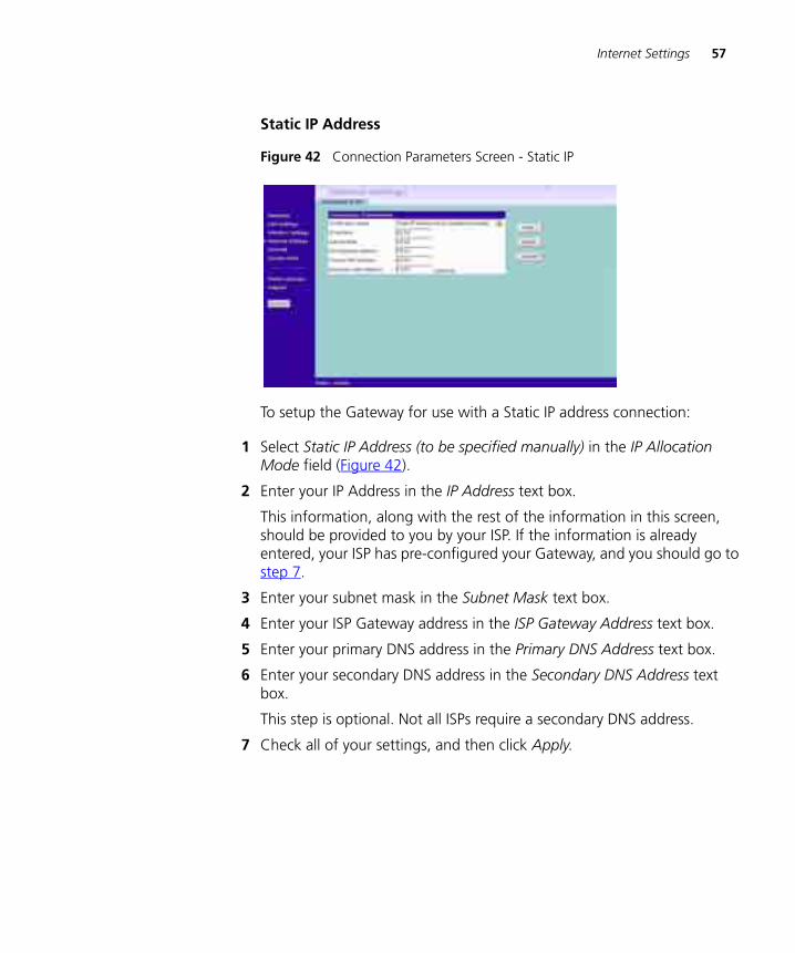
Static IP Address
Figure 42 Connection Parameters Screen - Static IP
To setup the Gateway for use with a Static IP address connection:
1 Select Static IP Address (to be specified manually) in the IP Allocation Mode field (Figure 42).
2 Enter your IP Address in the IP Address text box.
This information, along with the rest of the information in this screen, should be provided to you by your ISP. If the information is already entered, your ISP has pre-configured your Gateway, and you should go to step 7.
3 Enter your subnet mask in the Subnet Mask text box.
4 Enter your ISP Gateway address in the ISP Gateway Address text box.
5 Enter your primary DNS address in the Primary DNS Address text box.
6 Enter your secondary DNS address in the Secondary DNS Address text box.
This step is optional. Not all ISPs require a secondary DNS address.
7 Check all of your settings, and then click Apply.
58 CHAPTER 5: GATEWAY CONFIGURATION
Dynamic IP Address
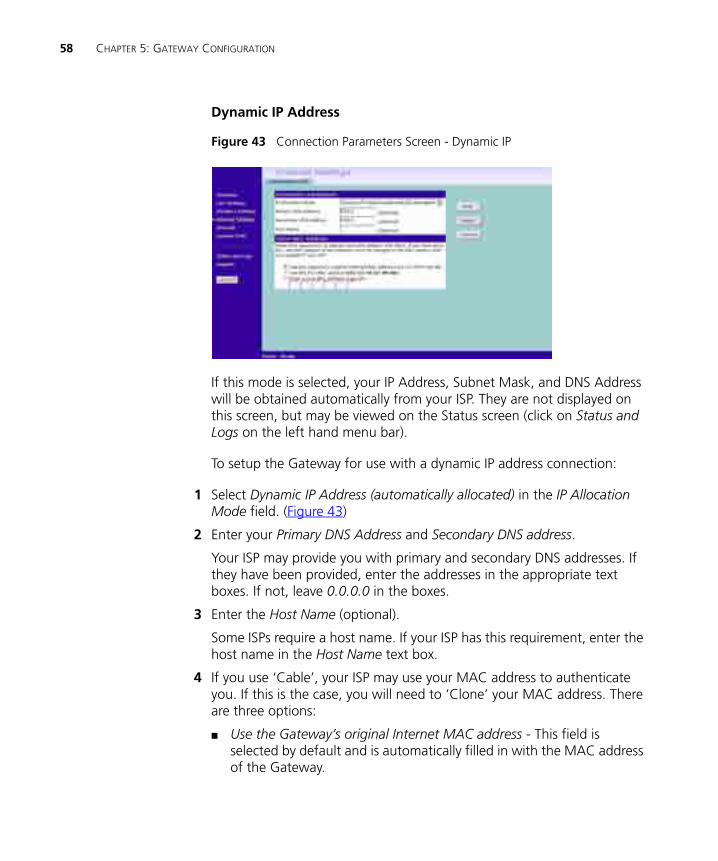
Figure 43 Connection Parameters Screen - Dynamic IP
If this mode is selected, your IP Address, Subnet Mask, and DNS Address will be obtained automatically from your ISP. They are not displayed on this screen, but may be viewed on the Status screen (click on Status and Logs on the left hand menu bar).
To setup the Gateway for use with a dynamic IP address connection:
1 Select Dynamic IP Address (automatically allocated) in the IP Allocation Mode field. (Figure 43)
2 Enter your Primary DNS Address and Secondary DNS address.
Your ISP may provide you with primary and secondary DNS addresses. If they have been provided, enter the addresses in the appropriate text boxes. If not, leave 0.0.0.0 in the boxes.
3 Enter the Host Name (optional).
Some ISPs require a host name. If your ISP has this requirement, enter the host name in the Host Name text box.
4 If you use ‘Cable’, your ISP may use your MAC address to authenticate you. If this is the case, you will need to ‘Clone’ your MAC address. There are three options:
■ Use the Gateway’s original Internet MAC address - This field is selected by default and is automatically filled in with the MAC address of the Gateway.
Internet Settings 59
■ Use this PC’s MAC address - This field is automatically filled in with the MAC address of the PC you are using to configure the Gateway. You should use this address only if you were previously using this computer to connect directly to your modem.
■ Enter a new MAC address manually - Use this option if you want to specify a new MAC address. Enter the new MAC address.
5 Check all settings and click Apply.
PPP over Ethernet
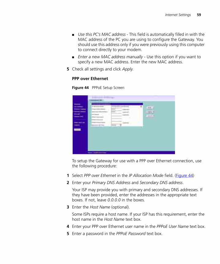
Figure 44 PPPoE Setup Screen
To setup the Gateway for use with a PPP over Ethernet connection, use the following procedure:
1 Select PPP over Ethernet in the IP Allocation Mode field. (Figure 44)
2 Enter your Primary DNS Address and Secondary DNS address.
Your ISP may provide you with primary and secondary DNS addresses. If they have been provided, enter the addresses in the appropriate text boxes. If not, leave 0.0.0.0 in the boxes.
3 Enter the Host Name (optional).
Some ISPs require a host name. If your ISP has this requirement, enter the host name in the Host Name text box.
4 Enter your PPP over Ethernet user name in the PPPoE User Name text box.
5 Enter a password in the PPPoE Password text box.
60 CHAPTER 5: GATEWAY CONFIGURATION
6 Enter your PPP over Ethernet service name in the PPPoE Service Name text box. Not all ISPs require a PPPoE service name. Only enter a service name if your ISP requires this.
7 Select an idle time from the Maximum Idle Time drop-down list.
This value will correspond to the amount of idle time (no Internet activity) that will pass before the Gateway automatically ends your PPP over Ethernet session.
Since the Gateway contains its own PPPoE client, you no longer need to run PPPoE client software on your computer to access the Internet.
PPTP
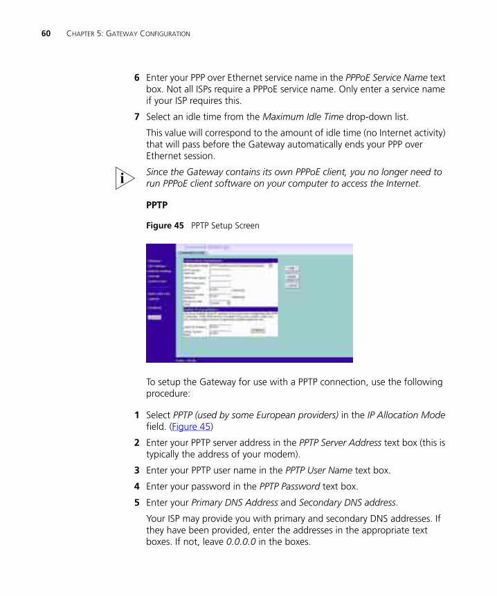
Figure 45 PPTP Setup Screen
To setup the Gateway for use with a PPTP connection, use the following procedure:
1 Select PPTP (used by some European providers) in the IP Allocation Mode field. (Figure 45)
2 Enter your PPTP server address in the PPTP Server Address text box (this is typically the address of your modem).
3 Enter your PPTP user name in the PPTP User Name text box.
4 Enter your password in the PPTP Password text box.
5 Enter your Primary DNS Address and Secondary DNS address.
Your ISP may provide you with primary and secondary DNS addresses. If they have been provided, enter the addresses in the appropriate text boxes. If not, leave 0.0.0.0 in the boxes.
Firewall 61
6 Select an idle time from the Maximum Idle Time drop-down list.
This value will correspond to the amount of idle time (no Internet activity) that will pass before the Gateway automatically ends your PPTP session.
7 IP settings must be used when establishing a PPTP connection. Fill in the Initial IP Address and the Initial Subnet Mask fields if your ISP has provided you with these settings. Alternatively, if the PPTP server is located in your DSL modem, click Suggest to select an IP address on the same subnet as the PPTP server.
Firewall On the main frame of the Firewall setup screen is a menu with four tabs: Virtual Servers, Special Applications, PCs Privileges, and Security.
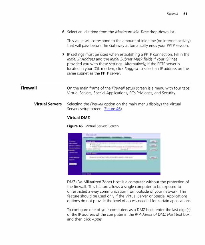
Virtual Servers Selecting the Firewall option on the main menu displays the Virtual Servers setup screen. (Figure 46)
Virtual DMZ
Figure 46 Virtual Servers Screen
DMZ (De-Militarized Zone) Host is a computer without the protection of the firewall. This feature allows a single computer to be exposed to unrestricted 2-way communication from outside of your network. This feature should be used only if the Virtual Server or Special Applications options do not provide the level of access needed for certain applications.
To configure one of your computers as a DMZ host, enter the last digit(s) of the IP address of the computer in the IP Address of DMZ Host text box, and then click Apply.
62 CHAPTER 5: GATEWAY CONFIGURATION
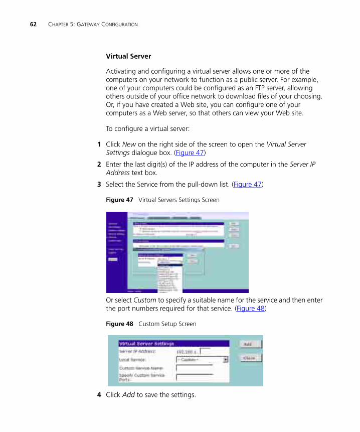
Virtual Server
Activating and configuring a virtual server allows one or more of the computers on your network to function as a public server. For example, one of your computers could be configured as an FTP server, allowing others outside of your office network to download files of your choosing. Or, if you have created a Web site, you can configure one of your computers as a Web server, so that others can view your Web site.
To configure a virtual server:
1 Click New on the right side of the screen to open the Virtual Server Settings dialogue box. (Figure 47)
2 Enter the last digit(s) of the IP address of the computer in the Server IP Address text box.
3 Select the Service from the pull-down list. (Figure 47)
Figure 47 Virtual Servers Settings Screen
Or select Custom to specify a suitable name for the service and then enter the port numbers required for that service. (Figure 48)
Figure 48 Custom Setup Screen
4 Click Add to save the settings.
Firewall 63
The port numbers are specified using a comma-separated list, with hyphens to denote port number ranges. So for example, entering 2, 3, 5-7 would cause ports 2, 3, 5, 6, and 7 to be activated.
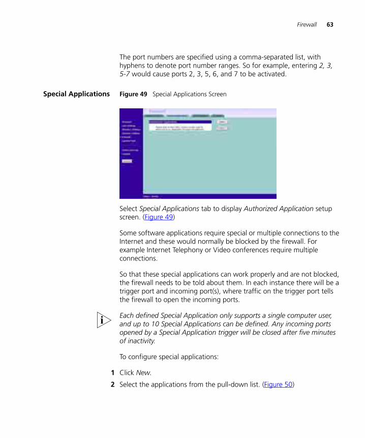
Special Applications Figure 49 Special Applications Screen
Select Special Applications tab to display Authorized Application setup screen. (Figure 49)
Some software applications require special or multiple connections to the Internet and these would normally be blocked by the firewall. For example Internet Telephony or Video conferences require multiple connections.
So that these special applications can work properly and are not blocked, the firewall needs to be told about them. In each instance there will be a trigger port and incoming port(s), where traffic on the trigger port tells the firewall to open the incoming ports.
Each defined Special Application only supports a single computer user, and up to 10 Special Applications can be defined. Any incoming ports opened by a Special Application trigger will be closed after five minutes of inactivity.
To configure special applications:
1 Click New.
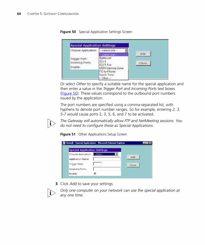
2 Select the applications from the pull-down list. (Figure 50)
64 CHAPTER 5: GATEWAY CONFIGURATION
Figure 50 Special Application Settings Screen
Or select Other to specify a suitable name for the special application and then enter a value in the Trigger Port and Incoming Ports text boxes (Figure 50). These values correspond to the outbound port numbers issued by the application.
The port numbers are specified using a comma-separated list, with hyphens to denote port number ranges. So for example, entering 2, 3, 5-7 would cause ports 2, 3, 5, 6, and 7 to be activated.
The Gateway will automatically allow FTP and NetMeeting sessions. You do not need to configure these as Special Applications.
Figure 51 Other Applications Setup Screen
3 Click Add to save your settings.
Only one computer on your network can use the special application at any one time.
Firewall 65
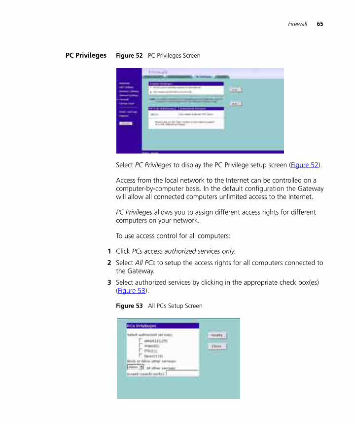
PC Privileges Figure 52 PC Privileges Screen
Select PC Privileges to display the PC Privilege setup screen (Figure 52).
Access from the local network to the Internet can be controlled on a computer-by-computer basis. In the default configuration the Gateway will allow all connected computers unlimited access to the Internet.
PC Privileges allows you to assign different access rights for different computers on your network.
To use access control for all computers:
1 Click PCs access authorized services only.
2 Select All PCs to setup the access rights for all computers connected to the Gateway.
3 Select authorized services by clicking in the appropriate check box(es) (Figure 53).
Figure 53 All PCs Setup Screen
66 CHAPTER 5: GATEWAY CONFIGURATION
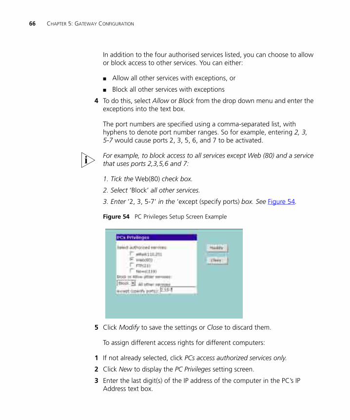
In addition to the four authorised services listed, you can choose to allow or block access to other services. You can either:
■ Allow all other services with exceptions, or
■ Block all other services with exceptions
4 To do this, select Allow or Block from the drop down menu and enter the exceptions into the text box.
The port numbers are specified using a comma-separated list, with hyphens to denote port number ranges. So for example, entering 2, 3, 5-7 would cause ports 2, 3, 5, 6, and 7 to be activated.
For example, to block access to all services except Web (80) and a service that uses ports 2,3,5,6 and 7:
1. Tick the Web(80) check box.
2. Select ‘Block’ all other services.
3. Enter ‘2, 3, 5-7’ in the ‘except (specify ports) box. See Figure 54.
Figure 54 PC Privileges Setup Screen Example
5 Click Modify to save the settings or Close to discard them.
To assign different access rights for different computers:
1 If not already selected, click PCs access authorized services only.
2 Click New to display the PC Privileges setting screen.
3 Enter the last digit(s) of the IP address of the computer in the PC’s IP Address text box.
Firewall 67
4 Select authorized services by clicking in the appropriate check box(es).
In addition to the four authorised services listed, you can choose to allow or block access to other services. You can either:
■ Allow all other services with exceptions, or
■ Block all other services with exceptions
See step 4 of the previous section for more details.
5 Click Add to save the settings.
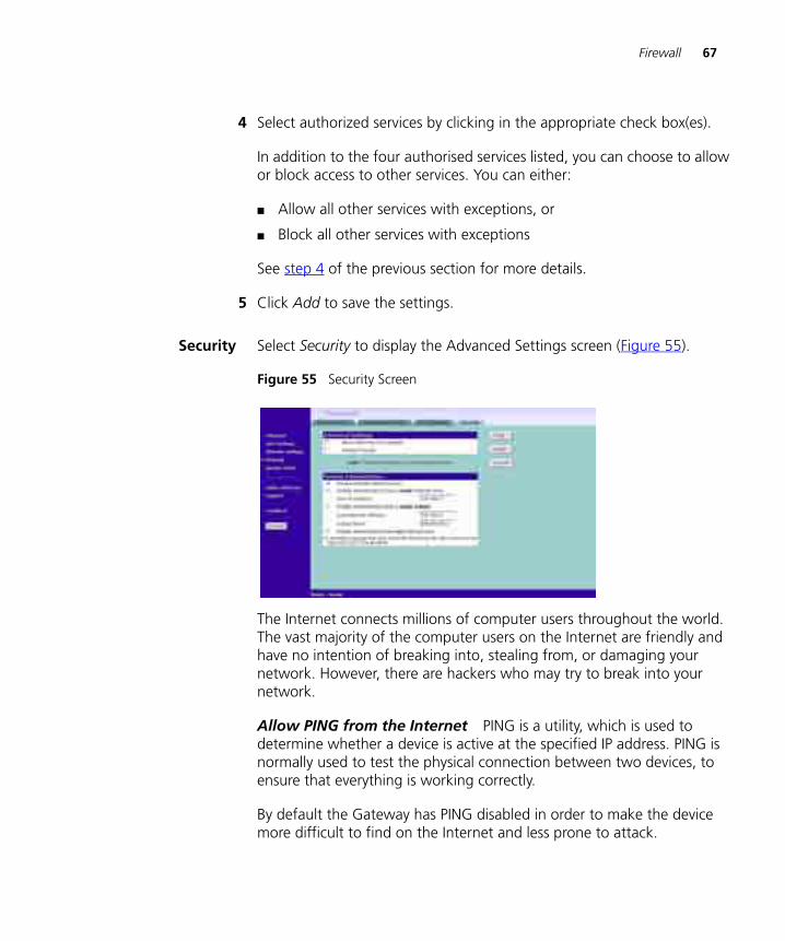
Security Select Security to display the Advanced Settings screen (Figure 55).
Figure 55 Security Screen
The Internet connects millions of computer users throughout the world. The vast majority of the computer users on the Internet are friendly and have no intention of breaking into, stealing from, or damaging your network. However, there are hackers who may try to break into your network.
Allow PING from the Internet PING is a utility, which is used to determine whether a device is active at the specified IP address. PING is normally used to test the physical connection between two devices, to ensure that everything is working correctly.
By default the Gateway has PING disabled in order to make the device more difficult to find on the Internet and less prone to attack.
68 CHAPTER 5: GATEWAY CONFIGURATION
This feature is enabled by clicking on the check box so that a tick can be seen and then select Apply.
3Com recommends that you leave this disabled.
Disable Firewall The Gateway contains a firewall that detects attack patterns used by hackers on the Internet and once detected will block their access to your network. When an attack is detected a log entry will be generated and the Alert LED will be lit for 2 seconds. The firewall will block Internet access to all unused TCP and UDP ports.
The Firewall is disabled by clicking on the check box so that a tick can be seen and then select Apply.
3Com recommends that you leave the firewall enabled.
Enabling Remote Administration
It is possible to administer the Gateway from four options:
1 Disable Remote Administration - This option is set as default.
2 Enable administration from a single Internet Host - Only the specified IP address can manage the Gateway. Any other users will be rejected.
3 Enable administration from a whole subnet - This option allows a number of users within a subnet to administer the Gateway.
4 Enable administration from any Internet Host - This options allows any host to access the administration pages.
To remotely administer your Gateway, enter http://xxx.xxx.xxx.xxx:8000 in the location bar of the browser running on the remote computer, where xxx.xxx.xxx.xxx is the Internet IP address of the Gateway. You may then login using the administration password.
Your Internet IP address can be found at the bottom of the screen. See Figure 55.
System Tools 69
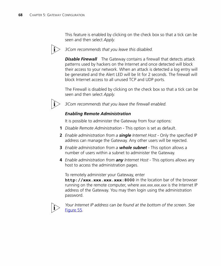
System Tools The main frame of the System Tools screen includes four administration items: Restart, Time Zone, Configuration, and Upgrade (Figure 56).
Restart Figure 56 Restart Screen
If your Gateway is not operating correctly, you can choose to restart the Gateway by selecting Restart the Gateway, simulating the effect of power cycling the unit. No configuration information will be lost but the log files will be erased. This function may be of use if you are experiencing problems and you wish to re-establish your Internet connection. Any network users who are currently accessing the Internet will have their access interrupted whilst the restart takes place, and they may need to reboot their computers when the restart has completed and the Gateway is operational again.
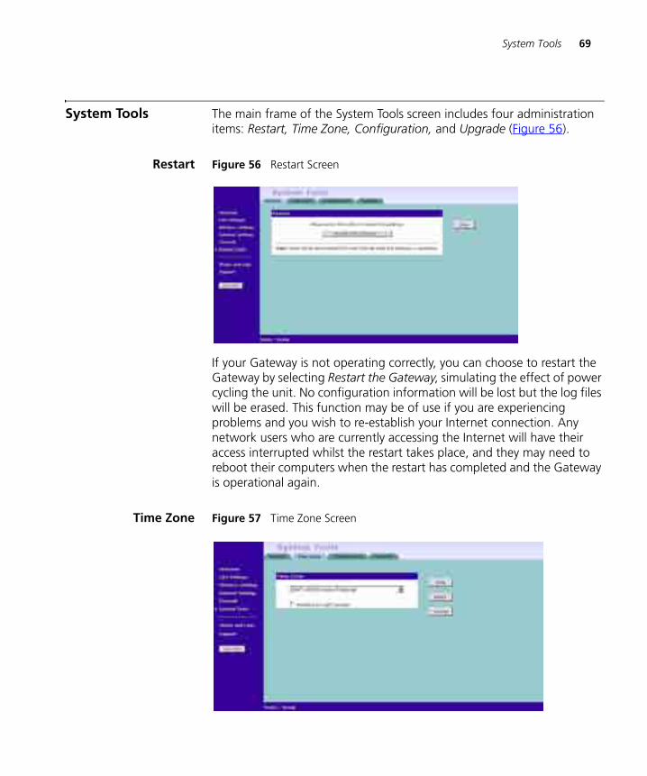
Time Zone Figure 57 Time Zone Screen
70 CHAPTER 5: GATEWAY CONFIGURATION
Choose the time zone that is closest to your actual location. The time zone setting is used by the system clock when displaying the correct time in the log files.
If you use Daylight saving tick the Enable Daylight savings box, and then click Apply (Figure 57).
The Gateway reads the correct time from NTP servers on the Internet and sets its system clock accordingly. The Daylight Savings option merely advances the system clock by one hour. It does not cause the system clock to be updated for daylight savings time automatically.
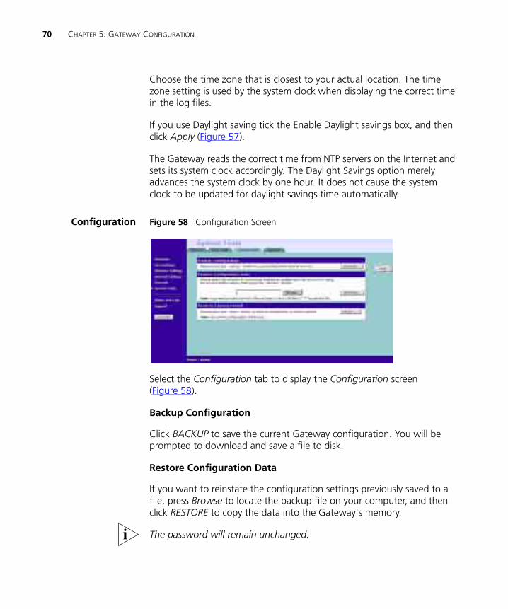
Configuration Figure 58 Configuration Screen
Select the Configuration tab to display the Configuration screen (Figure 58).
Backup Configuration
Click BACKUP to save the current Gateway configuration. You will be prompted to download and save a file to disk.
Restore Configuration Data
If you want to reinstate the configuration settings previously saved to a file, press Browse to locate the backup file on your computer, and then click RESTORE to copy the data into the Gateway's memory.
The password will remain unchanged.
System Tools 71
Reset to Factory Default
If you want to reset the settings on your Gateway to those that were loaded at the factory, click RESET. You will lose all your configuration changes. The Gateway LAN IP address will revert to 192.168.1.1, and the DHCP server on the LAN will be enabled. You may need to reconfigure and restart your computer to re-establish communication with the Gateway.
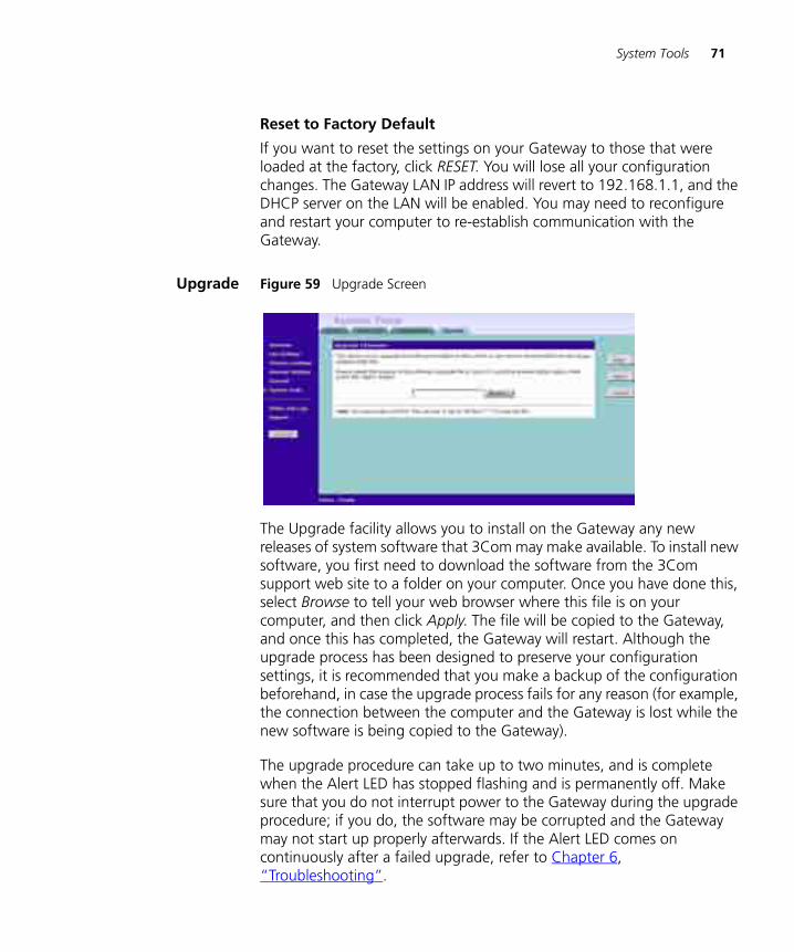
Upgrade Figure 59 Upgrade Screen
The Upgrade facility allows you to install on the Gateway any new releases of system software that 3Com may make available. To install new software, you first need to download the software from the 3Com support web site to a folder on your computer. Once you have done this, select Browse to tell your web browser where this file is on your computer, and then click Apply. The file will be copied to the Gateway, and once this has completed, the Gateway will restart. Although the upgrade process has been designed to preserve your configuration settings, it is recommended that you make a backup of the configuration beforehand, in case the upgrade process fails for any reason (for example, the connection between the computer and the Gateway is lost while the new software is being copied to the Gateway).
The upgrade procedure can take up to two minutes, and is complete when the Alert LED has stopped flashing and is permanently off. Make sure that you do not interrupt power to the Gateway during the upgrade procedure; if you do, the software may be corrupted and the Gateway may not start up properly afterwards. If the Alert LED comes on continuously after a failed upgrade, refer to Chapter 6, “Troubleshooting”.
72 CHAPTER 5: GATEWAY CONFIGURATION
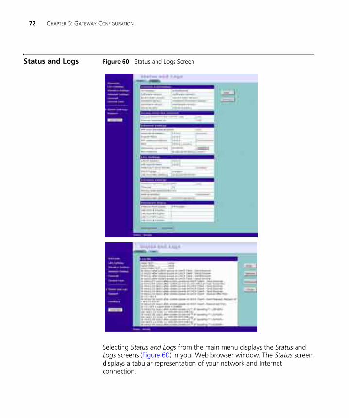
Status and Logs Figure 60 Status and Logs Screen
Selecting Status and Logs from the main menu displays the Status and Logs screens (Figure 60) in your Web browser window. The Status screen displays a tabular representation of your network and Internet connection.
Status and Logs 73
Status Status will display the current unit status, including a summary of the configuration
Logs Logs will allow you to view both the normal events, and security threats logged by the Gateway
You may be asked to refer to the information on the Status and Logs screens if you contact your supplier for technical support.
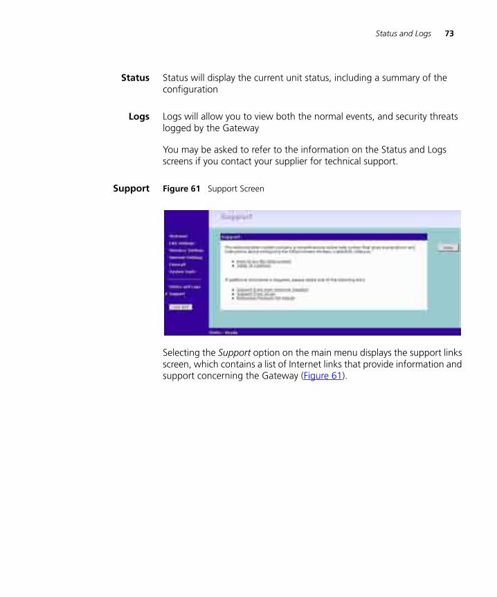
Support Figure 61 Support Screen
Selecting the Support option on the main menu displays the support links screen, which contains a list of Internet links that provide information and support concerning the Gateway (Figure 61).

74 CHAPTER 5: GATEWAY CONFIGURATION
6 TROUBLESHOOTING
Basic Connection Checks
■ Check that the Gateway is connected to your computers and to the cable/DSL modem, and that all the equipment is powered on. Check that the LAN and WAN port link status LEDs on the Gateway are illuminated, and that any corresponding LEDs on the cable/DSL modem and the NIC (Wireless Gateway only) are also illuminated.
■ Ensure that the computers have completed their start-up procedure and are ready for use. Some network interfaces may not be correctly initialised until the start-up procedure has completed.
■ If the link status LED does not illuminate for a port that is connected, check that you do not have a faulty cable. Try a different cable.
Browsing to the Gateway Configuration Screens
If you have connected your Gateway and computers together but cannot browse to the Gateway configuration screens, check the following:
■ Confirm that the physical connection between your computer and the Gateway is OK, and that the link status LEDs on the Gateway and NIC are illuminated and indicating the same speed (10Mbps or 100Mbps). Some NICs do not have status LEDs, in which case a diagnostic program may be available that can give you this information.
■ Ensure that you have configured your computer as described in Chapter 3, Setting Up Your Computers. Restart your computer while it is connected to the Gateway to ensure that your computer receives an IP address.
■ When entering the address of the Gateway into your web browser, ensure that you use the full URL including the http:// prefix (e.g. http://192.168.1.1).
■ If you cannot browse to the Gateway, use the winipcfg utility in Windows 95/98/ME to verify that your computer has received the correct address information from the Gateway. From the Start menu,
76 CHAPTER 6: TROUBLESHOOTING
choose Run and then enter winipcfg. Check that the computer has an IP address of the form 192.168.1.xxx (where xxx is in the range 2-254), the subnet mask is 255.255.255.0, and the default Gateway is 192.168.1.1 (the address of the Gateway). If these are not correct, use the Release and Renew functions to obtain a new IP address from the Gateway. Under Windows 2000, use the ipconfig command-line utility to perform the same functions.
■ If you still cannot browse to the Gateway, then use the Discovery program on the accompanying CD-ROM as described in Appendix A.
Connecting to the Internet
If you can browse to the Gateway configuration screens but cannot access sites on the Internet, check the following:
■ Confirm that the physical connection between the Gateway and the cable/DSL modem is OK, and that the link status LEDs on both Gateway and modem are illuminated.
■ Confirm that the connection between the modem and the cable/DSL interface is OK.
■ Ensure that you have entered the correct information into the Gateway configuration screens as required by your Internet Service Provider. Use the “Internet Settings” screen to verify this.
■ For DSL users, check that the PPPoE or PPTP user name, password and service name are correct, if these are required. Only enter a PPPoE service name if your ISP requires one.
■ For cable users, check whether your ISP required a fixed MAC (Ethernet) address. If so, use the Clone MAC Address feature in the Gateway to ensure that the correct MAC address is presented, as described on page 58.
■ Ensure that your computers are not configured to use a Web proxy. On Windows computers, this can be found under Control Panel > Internet Options > Connections.
Forgotten Password and Reset to Factory Defaults
If you can browse to the Gateway configuration screen but cannot log on because you do not know or have forgotten the password, follow the steps below to reset the Gateway to it’s factory default configuration.
CAUTION: All your configuration changes will be lost, and you will need to run the configuration wizard again before you can re-establish your
Wireless Networking 77
Gateway connection to the Internet. Also, other computer users will lose their network connections whilst this process is taking place, so choose a time when this would be convenient.
1 Remove power from the Gateway.
2 Disconnect all your computers and the cable/DSL modem from the Gateway.
3 Using a straight through Ethernet cable, connect the Ethernet Cable/DSL port on the rear of the Gateway to any one of the LAN ports.
4 Re-apply power to the Gateway. The Alert LED will flash as the Gateway starts up, and after approximately 30 seconds will start to flash more slowly (typically 2 seconds on, 2 seconds off). Once the Alert LED has started to flash slowly, remove power from the Gateway.
5 Remove the cable connecting the Cable/DSL port to the LAN port, and reconnect one of your computers to one of the Gateway LAN ports.
6 Re-apply power to the Gateway, and when the start-up sequence has completed, browse to:
http://192.168.1.1
and run the configuration wizard. You may need to restart your computer before you attempt this.
7 When the configuration wizard has completed, you may reconnect your network as it was before.
Wireless Networking
This section applies to the Wireless Cable/DSL Gateway only.
■ Ensure that you have a Wi-fi certified 802.11b wireless adapter for each wireless computer, and that it is correctly installed and configured. Verify that each Wireless computer has either Windows 95 or higher or MAC OS 8.5 or higher.
■ Verify that your wireless computers are configured to work in Infrastructure mode and not Ad Hoc mode. The Gateway contains an Access Point that is designed to operate in Infrastructure mode. Ad Hoc mode is not supported by the Gateway.
■ Check the status of the Gateway Wireless LED, it should be lit if wireless is enabled and will flash when there is wireless activity. If not lit go to “Wireless Settings” on page 46 and enable wireless networking.
■ Ensure that the TCP/IP settings for all devices are correct.
78 CHAPTER 6: TROUBLESHOOTING
■ Ensure that the Wireless Clients are using the same SSID or Service Area Name as the Gateway. The SSID is case-sensitive
■ Ensure that you are using the same level of security on all of your wireless computers (None, 40/64 or 128 bit) and that all devices are using the same keys, and the same order of keys where appropriate.
■ Ensure that you have the Wireless computer enabled in the list of allowed MAC addresses if you are using Wireless Connection control on the Gateway.
■ If you are having difficulty connecting or are operating at a low speed try changing the antenna positions on the rear of the Gateway. For more effective coverage you can try reorientating your antennae. Place one antenna vertically and one horizontally to improve coverage. Additionally consider moving the wireless computer closer to the Gateway to confirm that the building structure or fittings are not adversely affecting the connectivity. If this resolves the problem consider relocating the Wireless computer or the Gateway, or trying a different channel on the Gateway.
■ Sources of interference: The 2.4Ghz ISM band is used for 802.11b. This is generally a licence free band for low power applications, and you may have other devices at your location that operate in this frequency band. You should take care to ensure that there are no devices like microwave ovens for example close to the Gateway or wireless computers as this could affect receiver sensitivity and reduce the performance of your network. If you are unsure try relocating both the wireless computers and the Gateway to establish whether this problem exists.
■ Most wireless computer Adapters will scan the channels for the wireless Gateway. If a wireless computer has not located the Gateway then try initiating a search manually if the client software supports this feature or manually set the channel on your wireless computer to correspond to the Gateway channel number. Please refer to your Wireless computer adapter documentation and vendor to do this.
■ Speed of connection: The 802.11b standard will automatically choose the best speed depending on the quality of your connection. As the signal quality weakens then the speed falls back to a lower speed. The speeds are 11Mbps, 5.5Mbps, 2Mbps and 1Mbps. In general the closer you are to the Gateway the better the speed. If you are not achieving the speed you had anticipated then try moving the antenna on the Gateway or moving the Wireless computer closer to the Gateway. In an ideal network the Gateway should be located in the
Alert LED 79
centre of the network with Wireless computers distributed around it. Applications are generally available with the computer wireless card to carry out a site survey. Use this application to find the optimal siting for your wireless computer. Consult your Computer Card documentation and vendor for more details.
Alert LED The Alert LED will flash when the Gateway unit is first powered up while the system software checks the hardware for proper operation. Once the Gateway has started normal operation, the Alert LED will go out.
■ If the Alert LED does not go out following start up, but illuminates continuously, this indicates that the software has detected a possible fault with the hardware. Remove power from the Gateway, wait 10 seconds and then re-apply power. If the Alert LED comes on continuously again, then a fault has been detected. Locate the copy of the Gateway software on the accompanying CD-ROM or 3Com web site (http://www.3com.com) and upload it to the Gateway to see if this clears the fault (refer to “Recovering from Corrupted Software” below). If this does not fix the problem, contact your supplier for further advice.
■ During normal operation, you may notice the Alert LED lighting briefly from time to time. This indicates that the Gateway has detected a hacker attack from the Internet and has prevented it from harming your network. You need take no specific action on this, unless you decide that these attacks are happening frequently in which case you may wish to discuss this with your ISP. The Gateway logs such attacks, and this information is available through the Status and Logs screens.
Recovering from Corrupted Software
If the Alert LED remains permanently on following power-up, it is possible that the system software has become corrupted. In this condition, the Gateway will enter a “recovery” state; DHCP is disabled, and the LAN IP address is set to 192.168.1.1. Follow the instructions below to upload a new copy of the system software to a Gateway unit in this state.
Ensure that one of your computers has a copy of the new software image file stored on its hard disk or available on CD-ROM.
The latest software is available on 3Com’s Web site at:
www.3com.com.
80 CHAPTER 6: TROUBLESHOOTING
1 Remove power from the Gateway and disconnect the Cable/DSL modem and all your computers, except for the one computer with the software image.
2 You will need to reconfigure this computer with the following static IP address information:
■ IP address: 192.168.1.2
■ Subnet mask: 255.255.255.0
■ Default Gateway address: 192.168.1.1
3 Restart the computer, and re-apply power to the Gateway.
4 Using the Web browser on the computer, enter the following URL in the location bar:
http://192.168.1.1.
This will connect you to the Microcode Recovery utility in the Gateway.
5 Follow the on-screen instructions. Enter the path and filename of the software image file.
6 When the upload has completed, the Gateway will restart, run the self-test and, if successful, resume normal operation. The Alert LED will go out.
7 Refer to the Installation Guide to reconnect your Gateway to the Cable/DSL modem and the computers in your network. Do not forget to reconfigure the computer you used for the software upload.
If the Gateway does not resume normal operation following the upload, it may be faulty. Contact your supplier for advice.
Frequently Asked Questions
How do I reset the Gateway to Factory Defaults?
See “Forgotten Password and Reset to Factory Defaults” on page 76.
How many computers on the LAN does the Gateway support?
A maximum of 253 computers on the LAN are supported.
How many wireless clients does the Wireless Cable/DSL Gateway support?
A maximum of 32 wireless clients are supported.
Frequently Asked Questions 81
There are only 4 LAN ports on the Gateway. How are additional computers connected?
You can expand the number of connections available on your LAN by using hubs, switches and wireless access points connected to the Gateway. 3Com wireless access points and OfficeConnect hubs and switches provide a simple, reliable means of expanding your network; contact your supplier for more information, or visit:
http://www.3com.com/
Does the Gateway support virtual private networks (VPNs)?
The Gateway supports VPN passthrough, which allows VPN clients on the LAN to communicate with VPN hosts on the Internet. It is also possible to set up VPN hosts on your LAN that clients elsewhere on the Internet can connect to, but this is not a recommended configuration.
Where can I download software upgrades for the Gateway?
Upgrades to the Gateway software are posted on the 3Com support web site, accessible by visiting:
http://www.3com.com.
What other online resources are there?
The 3Com Knowledgebase at:
http://knowledgebase.3com.com
is a database of technical information covering all 3Com products. It is updated daily with information from 3Com technical support services, and it is available 24 hours a day, 7 days a week.

82 CHAPTER 6: TROUBLESHOOTING
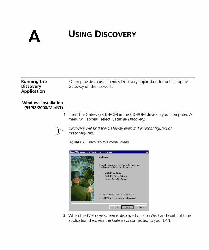
A
USING DISCOVERYRunning the Discovery Application
3Com provides a user friendly Discovery application for detecting the Gateway on the network.
Windows Installation(95/98/2000/Me/NT)
1 Insert the Gateway CD-ROM in the CD-ROM drive on your computer. A menu will appear; select Gateway Discovery.
Discovery will find the Gateway even if it is unconfigured or misconfigured.
Figure 62 Discovery Welcome Screen
2 When the Welcome screen is displayed click on Next and wait until the application discovers the Gateways connected to your LAN.
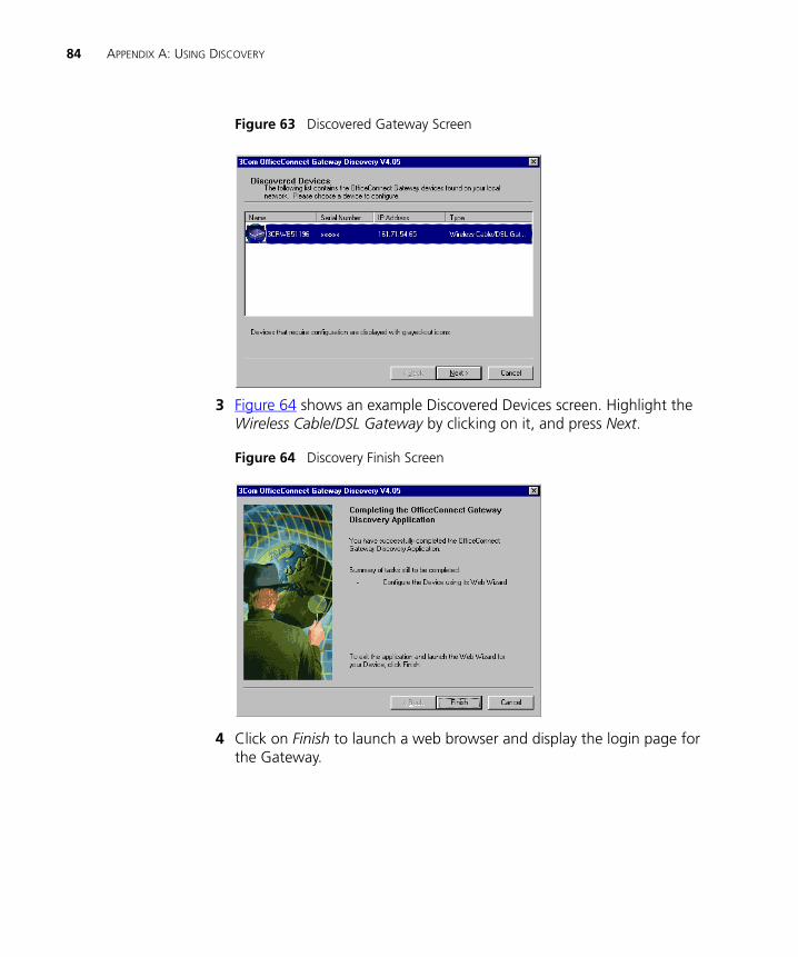
84 APPENDIX A: USING DISCOVERY
Figure 63 Discovered Gateway Screen
3 Figure 64 shows an example Discovered Devices screen. Highlight the Wireless Cable/DSL Gateway by clicking on it, and press Next.
Figure 64 Discovery Finish Screen
4 Click on Finish to launch a web browser and display the login page for the Gateway.
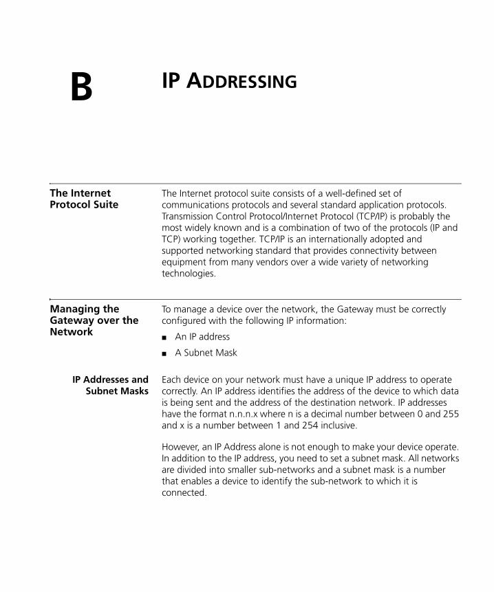
B
IP ADDRESSINGThe Internet Protocol Suite
The Internet protocol suite consists of a well-defined set of communications protocols and several standard application protocols. Transmission Control Protocol/Internet Protocol (TCP/IP) is probably the most widely known and is a combination of two of the protocols (IP and TCP) working together. TCP/IP is an internationally adopted and supported networking standard that provides connectivity between equipment from many vendors over a wide variety of networking technologies.
Managing the Gateway over the Network
To manage a device over the network, the Gateway must be correctly configured with the following IP information:
■ An IP address
■ A Subnet Mask
IP Addresses andSubnet Masks
Each device on your network must have a unique IP address to operate correctly. An IP address identifies the address of the device to which data is being sent and the address of the destination network. IP addresses have the format n.n.n.x where n is a decimal number between 0 and 255 and x is a number between 1 and 254 inclusive.
However, an IP Address alone is not enough to make your device operate. In addition to the IP address, you need to set a subnet mask. All networks are divided into smaller sub-networks and a subnet mask is a number that enables a device to identify the sub-network to which it is connected.
86 APPENDIX B: IP ADDRESSING
For your network to work correctly, all devices on the network must have:
■ The same sub-network address.
■ The same subnet mask.
The only value that will be different is the specific host device number. This value must always be unique.
An example IP address is ‘192.168.100.8’. However, the size of the network determines the structure of this IP Address. In using the Gateway, you will probably only encounter two types of IP Address and subnet mask structures.
Type One
In a small network, the IP address of ‘192.168.100.8’ is split into two parts:
■ Part one (‘192.168.100’) identifies the network on which the device resides.
■ Part two (‘.8’) identifies the device within the network.
This type of IP Address operates on a subnet mask of ‘255.255.255.0’.
See Table 3 for an example about how a network with three computers and a Gateway might be configured.
Table 3 IP Addressing and Subnet Masking
Type Two
In larger networks, where there are more devices, the IP address of ‘192.168.100.8’ is, again, split into two parts but is structured differently:
■ Part one (‘192.168’) identifies the network on which the device resides.
■ Part two (‘.100.8’) identifies the device within the network.
Device IP Address Subnet Mask
PC 1 192.168.100.8 255.255.255.0
PC 2 192.168.100.33 255.255.255.0
PC 3 192.168.100.188 255.255.255.0
Gateway 192.168.100.72 255.255.255.0
How does a Device Obtain an IP Address and Subnet Mask? 87
This type of IP Address operates on a subnet mask of ‘255.255.0.0’.
See Table 4 for an example about how a network (only four computers represented) and a Gateway might be configured.
Table 4 IP Addressing and Subnet Masking
How does a Device Obtain an IP Address and Subnet Mask?
There are three different ways to obtain an IP address and the subnet mask. These are:
■ Dynamic Host Configuration Protocol (DHCP) Addressing
■ Static Addressing
■ Automatic Addressing (Auto-IP Addressing)
DHCP Addressing The Gateway contains a DHCP server, which allows computers on your network to obtain an IP address and subnet mask automatically. DHCP assigns a temporary IP address and subnet mask which gets reallocated once you disconnect from the network.
DHCP will work on any client Operating System such as Windows® 95, Windows 98 or Windows NT 4.0. Also, using DHCP means that the same IP address and subnet mask will never be duplicated for devices on the network. DHCP is particularly useful for networks with large numbers of users on them.
Static Addressing You must enter an IP Address and the subnet mask manually on every device. Using a static IP and subnet mask means the address is permanently fixed.
Auto-IP Addressing Network devices use automatic IP addressing if they are configured to acquire an address using DHCP but are unable to contact a DHCP server. Automatic IP addressing is a scheme where devices allocate themselves
Device IP Address Subnet Mask
PC 1 192.168.100.8 255.255.0.0
PC 2 192.168.201.30 255.255.0.0
PC 3 192.168.113.155 255.255.0.0
PC 4 192.168.002.230 255.255.0.0
Gateway 192.168.002.72 255.255.0.0
88 APPENDIX B: IP ADDRESSING
an IP address at random from the industry standard subnet of 169.254.x.x (with a subnet mask of 255.255.0.0). If two devices allocate themselves the same address, the conflict is detected and one of the devices allocates itself a new address.
Automatic IP addressing support was introduced by Microsoft in the Windows 98 operating system and is also supported in Windows 2000.
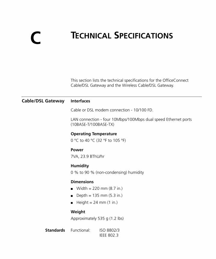
C
TECHNICAL SPECIFICATIONSThis section lists the technical specifications for the OfficeConnect Cable/DSL Gateway and the Wireless Cable/DSL Gateway.
Cable/DSL Gateway Interfaces
Cable or DSL modem connection - 10/100 FD.
LAN connection - four 10Mbps/100Mbps dual speed Ethernet ports (10BASE-T/100BASE-TX)
Operating Temperature
0 °C to 40 °C (32 °F to 105 °F)
Power
7VA, 23.9 BThU/hr
Humidity
0 % to 90 % (non-condensing) humidity
Dimensions
■ Width = 220 mm (8.7 in.)
■ Depth = 135 mm (5.3 in.)
■ Height = 24 mm (1 in.)
Weight
Approximately 535 g (1.2 lbs)
Standards Functional: ISO 8802/3IEEE 802.3
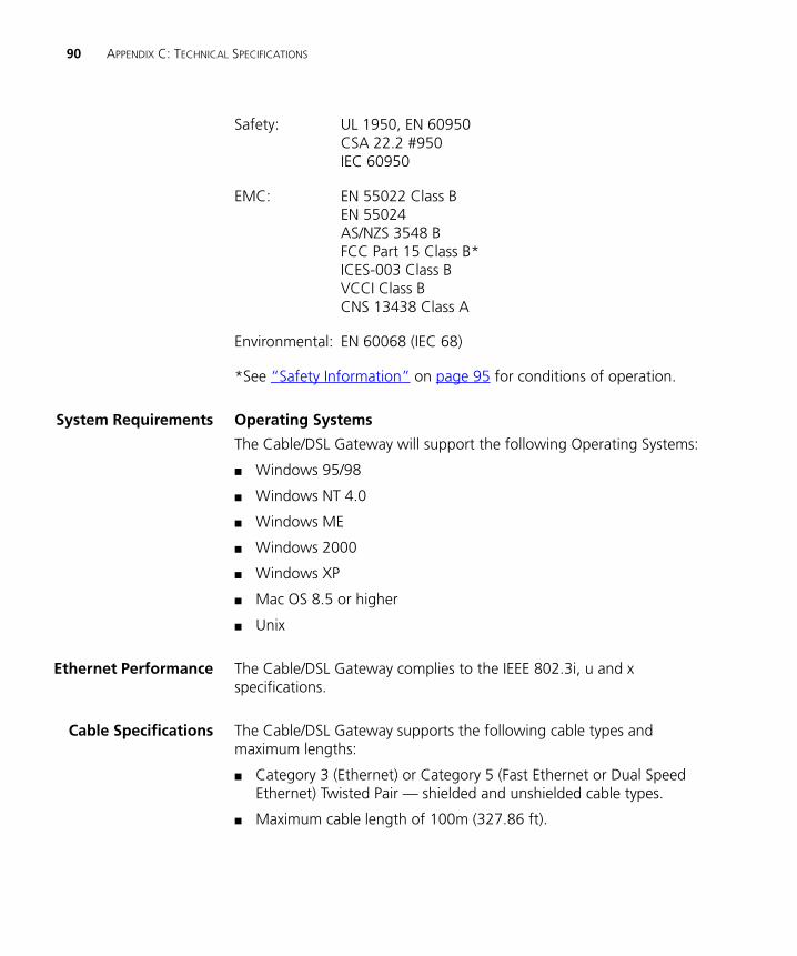
90 APPENDIX C: TECHNICAL SPECIFICATIONS
Safety: UL 1950, EN 60950CSA 22.2 #950IEC 60950
EMC: EN 55022 Class BEN 55024AS/NZS 3548 BFCC Part 15 Class B*ICES-003 Class BVCCI Class BCNS 13438 Class A
Environmental: EN 60068 (IEC 68)
*See “Safety Information” on page 95 for conditions of operation.
System Requirements Operating Systems
The Cable/DSL Gateway will support the following Operating Systems:
■ Windows 95/98
■ Windows NT 4.0
■ Windows ME
■ Windows 2000
■ Windows XP
■ Mac OS 8.5 or higher
■ Unix
Ethernet Performance The Cable/DSL Gateway complies to the IEEE 802.3i, u and x specifications.
Cable Specifications The Cable/DSL Gateway supports the following cable types and maximum lengths:
■ Category 3 (Ethernet) or Category 5 (Fast Ethernet or Dual Speed Ethernet) Twisted Pair — shielded and unshielded cable types.
■ Maximum cable length of 100m (327.86 ft).
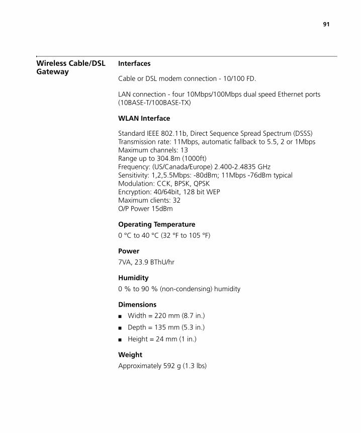
91
Wireless Cable/DSL Gateway
Interfaces
Cable or DSL modem connection - 10/100 FD.
LAN connection - four 10Mbps/100Mbps dual speed Ethernet ports (10BASE-T/100BASE-TX)
WLAN Interface
Standard IEEE 802.11b, Direct Sequence Spread Spectrum (DSSS)Transmission rate: 11Mbps, automatic fallback to 5.5, 2 or 1MbpsMaximum channels: 13Range up to 304.8m (1000ft)Frequency: (US/Canada/Europe) 2.400-2.4835 GHzSensitivity: 1,2,5.5Mbps: -80dBm; 11Mbps -76dBm typicalModulation: CCK, BPSK, QPSKEncryption: 40/64bit, 128 bit WEPMaximum clients: 32O/P Power 15dBm
Operating Temperature
0 °C to 40 °C (32 °F to 105 °F)
Power
7VA, 23.9 BThU/hr
Humidity
0 % to 90 % (non-condensing) humidity
Dimensions
■ Width = 220 mm (8.7 in.)
■ Depth = 135 mm (5.3 in.)
■ Height = 24 mm (1 in.)
Weight
Approximately 592 g (1.3 lbs)
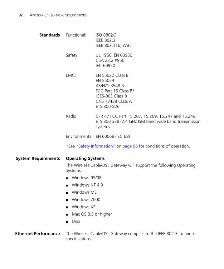
92 APPENDIX C: TECHNICAL SPECIFICATIONS
Standards Functional: ISO 8802/3IEEE 802.3IEEE 802.11b, WiFi
Safety: UL 1950, EN 60950CSA 22.2 #950IEC 60950
EMC: EN 55022 Class BEN 55024AS/NZS 3548 BFCC Part 15 Class B*ICES-003 Class BCNS 13438 Class AETS 300-826
Radio CFR 47 FCC Part 15.207, 15.209, 15.247 and 15.249. ETS 300 328 (2.4 GHz ISM band wide band transmission systems.
Environmental: EN 60068 (IEC 68)
*See “Safety Information” on page 95 for conditions of operation.
System Requirements Operating Systems
The Wireless Cable/DSL Gateway will support the following Operating Systems:
■ Windows 95/98
■ Windows NT 4.0
■ Windows ME
■ Windows 2000
■ Windows XP
■ Mac OS 8.5 or higher
■ Unix
Ethernet Performance The Wireless Cable/DSL Gateway complies to the IEEE 802.3i, u and x specifications.
93
Wireless Performance The Wireless Cable/DSL Gateway complies with the IEEE 802.11b specification and conforms to the WiFi interoperability test standard.
Cable Specifications The Wireless Cable/DSL Gateway supports the following cable types and maximum lengths:
■ Category 3 (Ethernet) or Category 5 (Fast Ethernet or Dual Speed Ethernet) Twisted Pair — shielded and unshielded cable types.
■ Maximum cable length of 100m (327.86 ft).

94 APPENDIX C: TECHNICAL SPECIFICATIONS
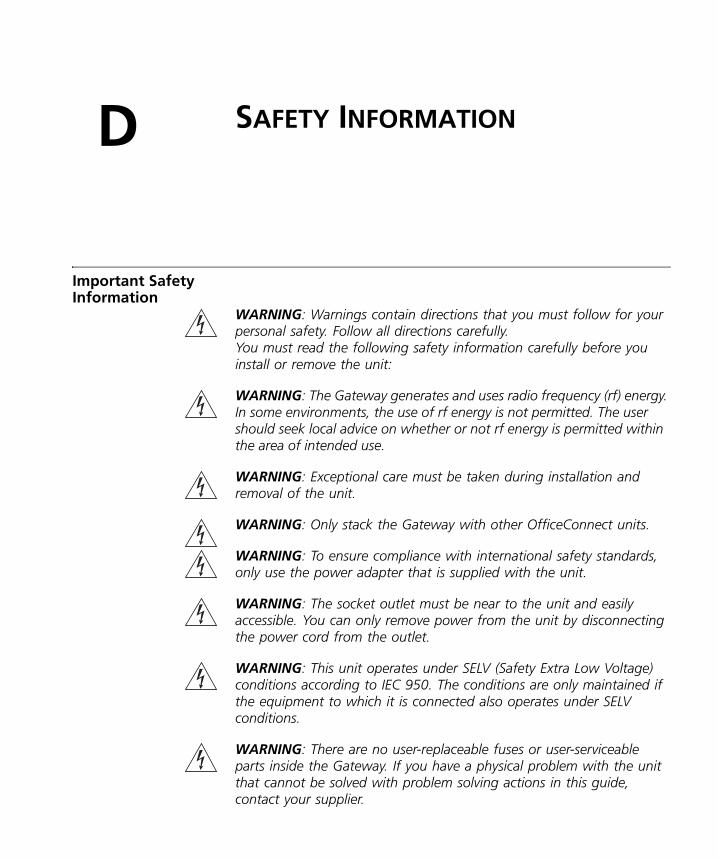
D
SAFETY INFORMATIONImportant Safety Information
WARNING: Warnings contain directions that you must follow for your personal safety. Follow all directions carefully.You must read the following safety information carefully before you install or remove the unit:
WARNING: The Gateway generates and uses radio frequency (rf) energy. In some environments, the use of rf energy is not permitted. The user should seek local advice on whether or not rf energy is permitted within the area of intended use.
WARNING: Exceptional care must be taken during installation and removal of the unit.
WARNING: Only stack the Gateway with other OfficeConnect units.
WARNING: To ensure compliance with international safety standards, only use the power adapter that is supplied with the unit.
WARNING: The socket outlet must be near to the unit and easily accessible. You can only remove power from the unit by disconnecting the power cord from the outlet.
WARNING: This unit operates under SELV (Safety Extra Low Voltage) conditions according to IEC 950. The conditions are only maintained if the equipment to which it is connected also operates under SELV conditions.
WARNING: There are no user-replaceable fuses or user-serviceable parts inside the Gateway. If you have a physical problem with the unit that cannot be solved with problem solving actions in this guide, contact your supplier.
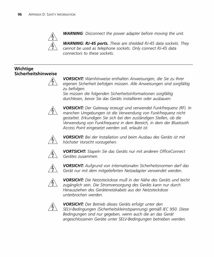
96 APPENDIX D: SAFETY INFORMATION
WARNING: Disconnect the power adapter before moving the unit.
WARNING: RJ-45 ports. These are shielded RJ-45 data sockets. They cannot be used as telephone sockets. Only connect RJ-45 data connectors to these sockets.
Wichtige Sicherheitshinweise
VORSICHT: Warnhinweise enthalten Anweisungen, die Sie zu Ihrer eigenen Sicherheit befolgen müssen. Alle Anweisungen sind sorgfältig zu befolgen. Sie müssen die folgenden Sicherheitsinformationen sorgfältig durchlesen, bevor Sie das Geräts installieren oder ausbauen:
VORSICHT: Der Gateway erzeugt und verwendet Funkfrequenz (RF). In manchen Umgebungen ist die Verwendung von Funkfrequenz nicht gestattet. Erkundigen Sie sich bei den zuständigen Stellen, ob die Verwendung von Funkfrequenz in dem Bereich, in dem der Bluetooth Access Point eingesetzt werden soll, erlaubt ist.
VORSICHT: Bei der Installation und beim Ausbau des Geräts ist mit höchster Vorsicht vorzugehen.
VORTSICHT: Stapeln Sie das Geräts nur mit anderen OfficeConnect Gerätes zusammen.
VORSICHT: Aufgrund von internationalen Sicherheitsnormen darf das Gerät nur mit dem mitgelieferten Netzadapter verwendet werden.
VORSICHT: Die Netzsteckdose muß in der Nähe des Geräts und leicht zugänglich sein. Die Stromversorgung des Geräts kann nur durch Herausziehen des Gerätenetzkabels aus der Netzsteckdose unterbrochen werden.
VORSICHT: Der Betrieb dieses Geräts erfolgt unter den SELV-Bedingungen (Sicherheitskleinstspannung) gemäß IEC 950. Diese Bedingungen sind nur gegeben, wenn auch die an das Gerät angeschlossenen Geräte unter SELV-Bedingungen betrieben werden.
97
VORSICHT: Es sind keine von dem Benutzer zu ersetzende oder zu wartende Teile in dem Gerät vorhanden. Wenn Sie ein Problem mit dem Gateway haben, das nicht mittels der Fehleranalyse in dieser Anleitung behoben werden kann, setzen Sie sich mit Ihrem Lieferanten in Verbindung.
VORSICHT: Vor dem Ausbau des Geräts das Netzadapterkabel herausziehen.
VORSICHT: RJ-45-Anschlüsse. Dies sind abgeschirmte RJ-45-Datenbuchsen. Sie können nicht als Telefonanschlußbuchsen verwendet werden. An diesen Buchsen dürfen nur RJ-45-Datenstecker angeschlossen werden.
Consignes importantes de sécurité AVERTISSEMENT: Les avertissements présentent des consignes que
vous devez respecter pour garantir votre sécurité personnelle. Vous devez respecter attentivement toutes les consignes.Nous vous demandons de lire attentivement les consignes suivantes de sécurité avant d’installer ou de retirer l’appareil:
AVERTISSEMENT: La Gateway fournit et utilise de l'énergie radioélectrique (radio fréquence -rf). L'utilisation de l'énergie radioélectrique est interdite dans certains environnements. L'utilisateur devra se renseigner sur l'autorisation de cette énergie dans la zone prévue.
AVERTISSEMENT: Faites très attention lors de l'installation et de la dépose du groupe.
AVERTISSEMENT: Seulement entasser le moyer avec les autres moyeux OfficeConnects.
AVERTISSEMENT: Pour garantir le respect des normes internationales de sécurité, utilisez uniquement l'adaptateur électrique remis avec cet appareil.
AVERTISSEMENT: La prise secteur doit se trouver à proximité de l’appareil et son accès doit être facile. Vous ne pouvez mettre l’appareil hors circuit qu'en débranchant son cordon électrique au niveau de cette prise.
98 APPENDIX D: SAFETY INFORMATION
AVERTISSEMENT: L’appareil fonctionne à une tension extrêmement basse de sécurité qui est conforme à la norme CEI 950. Ces conditions ne sont maintenues que si l'équipement auquel il est raccordé fonctionne dans les mêmes conditions.
AVERTISSEMENT: Il n’y a pas de parties remplaceables par les utilisateurs ou entretenues par les utilisateurs à l’intérieur du moyeu. Si vous avez un problème physique avec le moyeu qui ne peut pas être résolu avec les actions de la résolution des problèmes dans ce guide, contacter votre fournisseur.
AVERTISSEMENT: Débranchez l'adaptateur électrique avant de retirer cet appareil.
AVERTISSEMENT: Ports RJ-45. Il s'agit de prises femelles blindées de données RJ-45. Vous ne pouvez pas les utiliser comme prise de téléphone. Branchez uniquement des connecteurs de données RJ-45 sur ces prises femelles.
E
END USER SOFTWARE LICENCE AGREEMENT3Com CorporationEND USER SOFTWARE LICENSE AGREEMENTYOU SHOULD CAREFULLY READ THE FOLLOWING TERMS AND CONDITIONS BEFORE DOWNLOADING, INSTALLING AND USING THIS PRODUCT, THE USE OF WHICH IS LICENSED BY 3COM CORPORATION ("3COM") TO ITS CUSTOMERS FOR THEIR USE ONLY AS SET FORTH BELOW. DOWNLOADING, INSTALLING OR OTHERWISE USING ANY PART OF THE SOFTWARE OR DOCUMENTATION INDICATES THAT YOU ACCEPT THESE TERMS AND CONDITIONS. IF YOU DO NOT AGREE TO THE TERMS AND CONDITIONS OF THIS AGREEMENT, DO NOT DOWNLOAD, INSTALL OR OTHERWISE USE THE SOFTWARE OR DOCUMENTATION, DO NOT CLICK ON THE "I AGREE" OR SIMILAR BUTTON. AND IF YOU HAVE RECEIVED THE SOFTWARE AND DOCUMENTATION ON PHYSICAL MEDIA, RETURN THE ENTIRE PRODUCT WITH THE SOFTWARE AND DOCUMENTATION UNUSED TO THE SUPPLIER WHERE YOU OBTAINED IT.
LICENSE: 3Com grants you a nonexclusive, nontransferable (except as specified herein) license to use the accompanying software program(s) in executable form (the "Software") and accompanying documentation (the "Documentation"), subject to the terms and restrictions set forth in this Agreement. You are not permitted to lease, rent, distribute or sublicense (except as specified herein) the Software or Documentation or to use the Software or Documentation in a time-sharing arrangement or in any other unauthorized manner. Further, no license is granted to you in the human readable code of the Software (source code). Except as provided below, this Agreement does not grant you any rights to patents, copyrights, trade secrets, trademarks, or any other rights with respect to the Software or Documentation.
Subject to the restrictions set forth herein, the Software is licensed to be used on any workstation or any network server owned by or leased to you, for your internal use, provided that the Software is used only in connection with this 3Com product. You may reproduce and provide one (1) copy of the Software and Documentation for each such workstation or network server on which the Software is used as permitted hereunder. Otherwise, the Software and Documentation may be copied only as essential for backup or archive purposes in support of your use of the Software as permitted hereunder. Each copy of the Software and Documentation must contain 3Com's and its licensors' proprietary rights and copyright notices in the same form as on the original. You agree not to remove or deface any portion of any legend provided on any licensed program or documentation delivered to you under this Agreement.
ASSIGNMENT; NO REVERSE ENGINEERING: You may transfer the Software, Documentation and the licenses granted herein to another party in the same country in which you obtained the Software and Documentation if the other party agrees in writing to accept and be bound by the terms and conditions of this Agreement. If you transfer the Software and Documentation, you must at the same time either transfer all copies of the Software and Documentation to the party or you must destroy any copies not transferred. Except as set forth above, you may not assign or transfer your rights under this Agreement.
Modification, reverse engineering, reverse compiling, or disassembly of the Software is expressly prohibited. However, if you are a European Union ("EU") resident, information necessary to achieve interoperability of the Software with other programs within the meaning of the EU Directive on the Legal Protection of Computer Programs is available to you from 3Com upon written request.
EXPORT RESTRICTIONS: The Software, including the Documentation and all related technical data (and any copies thereof) (collectively "Technical Data"), is subject to United States Export control laws and may be subject to export or import regulations in other countries. In addition, the Technical Data covered by this Agreement may contain data encryption code which is unlawful to export or transfer from the United States or country where you legally obtained it without an approved U.S. Department of Commerce export license and appropriate foreign export or import license, as required. You agree that you will not export or re-export the Technical Data (or any copies thereof) or any products utilizing the Technical Data in violation of any applicable laws or regulations of the United States or the country where you legally obtained it. You are responsible for obtaining any licenses to export, re-export or import the Technical Data.
In addition to the above, the Product may not be used, exported or re-exported (i) into or to a national or resident of any country to which the U.S. has embargoed; or (ii) to any one on the U.S. Commerce Department's Table of Denial Orders or the U.S. Treasury Department's list of Specially Designated Nationals.
TRADE SECRETS; TITLE: You acknowledge and agree that the structure, sequence and organization of the Software are the valuable trade secrets of 3Com and its suppliers. You agree to hold such trade secrets in confidence. You further acknowledge and agree that ownership of, and title to, the Software and Documentation and all subsequent copies thereof regardless of the form or media are held by 3Com and its suppliers.
UNITED STATES GOVERNMENT LEGENDS: The Software, Documentation and any other technical data provided hereunder is commercial in nature
100 APPENDIX E: END USER SOFTWARE LICENCE AGREEMENT
and developed solely at private expense. The Software is delivered as "Commercial Computer Software" as defined in DFARS 252.227-7014 (June 1995) or as a commercial item as defined in FAR 2.101(a) and as such is provided with only such rights as are provided in this Agreement, which is 3Com's standard commercial license for the Software. Technical data is provided with limited rights only as provided in DFAR 252.227-7015 (Nov. 1995) or FAR 52.227-14 (June 1987), whichever is applicable.
TERM AND TERMINATION: The licenses granted hereunder are perpetual unless terminated earlier as specified below. You may terminate the licenses and this Agreement at any time by destroying the Software and Documentation together with all copies and merged portions in any form. The licenses and this Agreement will also terminate immediately if you fail to comply with any term or condition of this Agreement. Upon such termination you agree to destroy the Software and Documentation, together with all copies and merged portions in any form.
LIMITED WARRANTIES AND LIMITATION OF LIABILITY: All warranties and limitations of liability applicable to the Software are as stated on the Limited Warranty Card or in the product manual, whether in paper or electronic form, accompanying the Software. Such warranties and limitations of liability are incorporated herein in their entirety by this reference.
GOVERNING LAW: This Agreement shall be governed by the laws of the State of California, U.S.A. excluding its conflicts of laws principles and excluding the United Nations Convention on Contracts for the International Sale of Goods.
SEVERABILITY: In the event any provision of this Agreement is found to be invalid, illegal or unenforceable, the validity, legality and enforceability of any of the remaining provisions shall not in any way be affected or impaired and a valid, legal and enforceable provision of similar intent and economic impact shall be substituted therefor.
ENTIRE AGREEMENT: This Agreement sets forth the entire understanding and agreement between you and 3Com and supersedes all prior agreements, whether written or oral, with respect to the Software and Documentation, and may be amended only in a writing signed by both parties.
Should you have any questions concerning this Agreement or if you desire to contact 3Com for any reason, please contact the 3Com subsidiary serving your country, or write:
3Com Corporation, 5400 Bayfront Plaza, P.O. Box 58145, Santa Clara, CA 95052-8145 (408) 326-5000
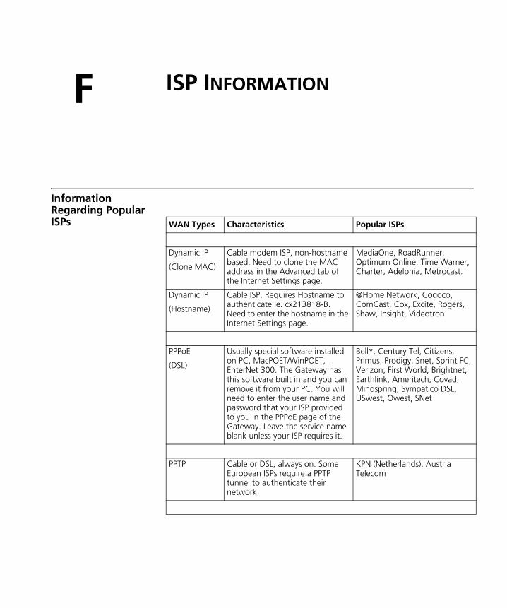
F
ISP INFORMATIONInformation Regarding Popular ISPs WAN Types Characteristics Popular ISPs
Dynamic IP
(Clone MAC)
Cable modem ISP, non-hostname based. Need to clone the MAC address in the Advanced tab of the Internet Settings page.
MediaOne, RoadRunner, Optimum Online, Time Warner, Charter, Adelphia, Metrocast.
Dynamic IP
(Hostname)
Cable ISP, Requires Hostname to authenticate ie. cx213818-B. Need to enter the hostname in the Internet Settings page.
@Home Network, Cogoco, ComCast, Cox, Excite, Rogers, Shaw, Insight, Videotron
PPPoE
(DSL)
Usually special software installed on PC, MacPOET/WinPOET, EnterNet 300. The Gateway has this software built in and you can remove it from your PC. You will need to enter the user name and password that your ISP provided to you in the PPPoE page of the Gateway. Leave the service name blank unless your ISP requires it.
Bell*, Century Tel, Citizens, Primus, Prodigy, Snet, Sprint FC, Verizon, First World, Brightnet, Earthlink, Ameritech, Covad, Mindspring, Sympatico DSL, USwest, Owest, SNet
PPTP Cable or DSL, always on. Some European ISPs require a PPTP tunnel to authenticate their network.
KPN (Netherlands), Austria Telecom
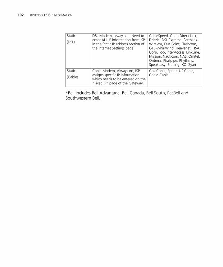
102 APPENDIX F: ISP INFORMATION
*Bell includes Bell Advantage, Bell Canada, Bell South, PacBell and Southwestern Bell.
Static
(DSL)
DSL Modem, always on. Need to enter ALL IP information from ISP in the Static IP address section of the Internet Settings page.
CableSpeed, Cnet, Direct Link, Drizzle, DSL Extreme, Earthlink Wireless, Fast Point, Flashcom, GTE-WhirlWind, Heavenet, HSA Corp, I-55, InterAccess, LinkLine, Mission, Nauticom, NAS, Omitel, Onterra, Phatpipe, Rhythms, Speakeasy, Sterling, XO, Zyan
Static
(Cable)
Cable Modem, Always on, ISP assigns specific IP information which needs to be entered on the “Fixed IP” page of the Gateway.
Cox Cable, Sprint, US Cable, Cable-Cable
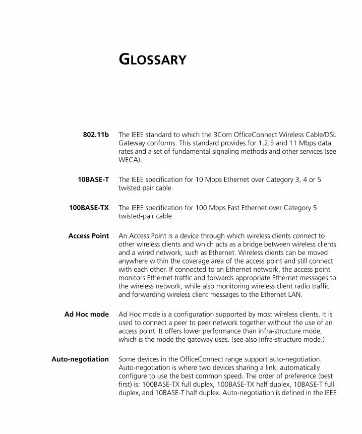
GLOSSARY
802.11b The IEEE standard to which the 3Com OfficeConnect Wireless Cable/DSL Gateway conforms. This standard provides for 1,2,5 and 11 Mbps data rates and a set of fundamental signaling methods and other services (see WECA).
10BASE-T The IEEE specification for 10 Mbps Ethernet over Category 3, 4 or 5 twisted pair cable.
100BASE-TX The IEEE specification for 100 Mbps Fast Ethernet over Category 5 twisted-pair cable.
Access Point An Access Point is a device through which wireless clients connect to other wireless clients and which acts as a bridge between wireless clients and a wired network, such as Ethernet. Wireless clients can be moved anywhere within the coverage area of the access point and still connect with each other. If connected to an Ethernet network, the access point monitors Ethernet traffic and forwards appropriate Ethernet messages to the wireless network, while also monitoring wireless client radio traffic and forwarding wireless client messages to the Ethernet LAN.
Ad Hoc mode Ad Hoc mode is a configuration supported by most wireless clients. It is used to connect a peer to peer network together without the use of an access point. It offers lower performance than infra-structure mode, which is the mode the gateway uses. (see also Infra-structure mode.)
Auto-negotiation Some devices in the OfficeConnect range support auto-negotiation. Auto-negotiation is where two devices sharing a link, automatically configure to use the best common speed. The order of preference (best first) is: 100BASE-TX full duplex, 100BASE-TX half duplex, 10BASE-T full duplex, and 10BASE-T half duplex. Auto-negotiation is defined in the IEEE
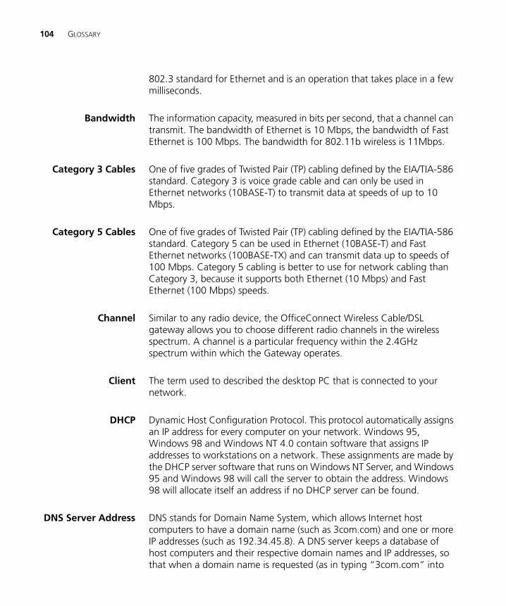
104 GLOSSARY
802.3 standard for Ethernet and is an operation that takes place in a few milliseconds.
Bandwidth The information capacity, measured in bits per second, that a channel can transmit. The bandwidth of Ethernet is 10 Mbps, the bandwidth of Fast Ethernet is 100 Mbps. The bandwidth for 802.11b wireless is 11Mbps.
Category 3 Cables One of five grades of Twisted Pair (TP) cabling defined by the EIA/TIA-586 standard. Category 3 is voice grade cable and can only be used in Ethernet networks (10BASE-T) to transmit data at speeds of up to 10 Mbps.
Category 5 Cables One of five grades of Twisted Pair (TP) cabling defined by the EIA/TIA-586 standard. Category 5 can be used in Ethernet (10BASE-T) and Fast Ethernet networks (100BASE-TX) and can transmit data up to speeds of 100 Mbps. Category 5 cabling is better to use for network cabling than Category 3, because it supports both Ethernet (10 Mbps) and Fast Ethernet (100 Mbps) speeds.
Channel Similar to any radio device, the OfficeConnect Wireless Cable/DSL gateway allows you to choose different radio channels in the wireless spectrum. A channel is a particular frequency within the 2.4GHz spectrum within which the Gateway operates.
Client The term used to described the desktop PC that is connected to your network.
DHCP Dynamic Host Configuration Protocol. This protocol automatically assigns an IP address for every computer on your network. Windows 95, Windows 98 and Windows NT 4.0 contain software that assigns IP addresses to workstations on a network. These assignments are made by the DHCP server software that runs on Windows NT Server, and Windows 95 and Windows 98 will call the server to obtain the address. Windows 98 will allocate itself an address if no DHCP server can be found.
DNS Server Address DNS stands for Domain Name System, which allows Internet host computers to have a domain name (such as 3com.com) and one or more IP addresses (such as 192.34.45.8). A DNS server keeps a database of host computers and their respective domain names and IP addresses, so that when a domain name is requested (as in typing “3com.com” into
GLOSSARY 105
your Internet browser), the user is sent to the proper IP address. The DNS server address used by the computers on your home network is the location of the DNS server your ISP has assigned.
DSL modem DSL stands for digital subscriber line. A DSL modem uses your existing phone lines to send and receive data at high speeds.
Encryption A method for providing a level of security to wireless data transmissions. The OfficeConnect Cable/DSL Gateway and Wireless Cable/DSL Gateway uses two levels of encryption; 40/64 bit and 128 bit. 128 bit is a more powerful level of encryption than 40/64 bit.
ESSID Extended Service Set Identifier. The ESSID is a unique identifier for your wireless network. You must have the same ESSID entered into the gateway and each of it's wireless clients.
Ethernet A LAN specification developed jointly by Xerox, Intel and Digital Equipment Corporation. Ethernet networks use CSMA/CD to transmit packets at a rate of 10 Mbps over a variety of cables.
Ethernet Address See MAC address.
Fast Ethernet An Ethernet system that is designed to operate at 100 Mbps.
Firewall Electronic protection that prevents anyone outside of your network from seeing your files or damaging your computers.
Full Duplex A system that allows packets to be transmitted and received at the same time and, in effect, doubles the potential throughput of a link.
Gateway A device that acts as a central hub by connecting to each computer's network interface card and managing the data traffic between the local network and the Internet.
Half Duplex A system that allows packets to transmitted and received, but not at the same time. Contrast with full duplex.
106 GLOSSARY
Hub A device that regenerates LAN traffic so that the transmission distance of that signal can be extended. Hubs are similar to repeaters, in that they connect LANs of the same type; however they connect more LANs than a repeater and are generally more sophisticated.
IEEE Institute of Electrical and Electronics Engineers. This American organization was founded in 1963 and sets standards for computers and communications.
IETF Internet Engineering Task Force. An organization responsible for providing engineering solutions for TCP/IP networks. In the network management area, this group is responsible for the development of the SNMP protocol.
Infra-structure mode Infra-Structure mode is the 802.11b configuration supported by the Gateway. You will need to ensure all of your clients are set up to use infra-structure mode in order for them to communicate with the Access Point built into your Gateway. (see also Ad Hoc mode)
IP Internet Protocol. IP is a layer 3 network protocol that is the standard for sending data through a network. IP is part of the TCP/IP set of protocols that describe the routing of packets to addressed devices. An IP address consists of 32 bits divided into two or three fields: a network number and a host number or a network number, a subnet number, and a host number.
IP Address Internet Protocol Address. A unique identifier for a device attached to a network using TCP/IP. The address is written as four octets separated with periods (full-stops), and is made up of a network section, an optional subnet section and a host section.
ISP Internet Service Provider. An ISP is a business that provides connectivity to the Internet for individuals and other businesses or organizations.
LAN Local Area Network. A network of end stations (such as PCs, printers, servers) and network devices (hubs and switches) that cover a relatively small geographic area (usually not larger than a floor or building). LANs are characterized by high transmission speeds over short distances (up to 1000 metres).
GLOSSARY 107
MAC Media Access Control. A protocol specified by the IEEE for determining which devices have access to a network at any one time.
MAC Address Media Access Control Address. Also called the hardware or physical address. A layer 2 address associated with a particular network device. Most devices that connect to a LAN have a MAC address assigned to them as they are used to identify other devices in a network. MAC addresses are 6 bytes long.
NAT Network Address Translation. NAT enables all the computers on your network to share one IP address. The NAT capability of the Gateway allows you to access the Internet from any computer on your home network without having to purchase more IP addresses from your ISP.
Network A Network is a collection of computers and other computer equipment that are connected for the purpose of exchanging information or sharing resources. Networks vary in size, some are within a single room, others span continents.
Network InterfaceCard (NIC)
A circuit board installed into a piece of computing equipment, for example, a computer, that enables you to connect it to the network. A NIC is also known as an adapter or adapter card.
Protocol A set of rules for communication between devices on a network. The rules dictate format, timing, sequencing and error control.
PPPoE Point-to-Point Protocol over Ethernet. Point-to-Point Protocol is a method of data transmission originally created for dial-up connections; PPPoE is for Ethernet connections.
PPTP Point-to-Point Tunneling Protocol is a method of secure data transmission between two remote sites over the internet.
RJ-45 A standard connector used to connect Ethernet networks. The "RJ" stands for "registered jack".
Server A computer in a network that is shared by multiple end stations. Servers provide end stations with access to shared network services such as computer files and printer queues.
108 GLOSSARY
SSID Service Set Identifier. Some vendors of wireless products use SSID interchangeably with ESSID.
Subnet Address An extension of the IP addressing scheme that allows a site to use a single IP network address for multiple physical networks.
Subnet mask A subnet mask, which may be a part of the TCP/IP information provided by your ISP, is a set of four numbers configured like an IP address. It is used to create IP address numbers used only within a particular network (as opposed to valid IP address numbers recognized by the Internet, which must assigned by InterNIC).
Subnets A network that is a component of a larger network.
Switch A device that interconnects several LANs to form a single logical LAN that comprises of several LAN segments. Switches are similar to bridges, in that they connect LANs of a different type; however they connect more LANs than a bridge and are generally more sophisticated.
TCP/IP Transmission Control Protocol/Internet Protocol. This is the name for two of the most well-known protocols developed for the interconnection of networks. Originally a UNIX standard, TCP/IP is now supported on almost all platforms, and is the protocol of the Internet.
TCP relates to the content of the data travelling through a network — ensuring that the information sent arrives in one piece when it reaches its destination. IP relates to the address of the end station to which data is being sent, as well as the address of the destination network.
Traffic The movement of data packets on a network.
WAN Wide Area Network. A network that connects computers located in geographically separate areas (for example, different buildings, cities, or countries). The Internet is an example of a wide area network.
WECA Wireless Ethernet Compatibility Alliance. An industry group formed to certify cross vendor interoperability and compatibility of 802.11b wireless networking products and to promote the standard for enterprise, small business and home environments. (see also 802.11b, Wi-Fi)
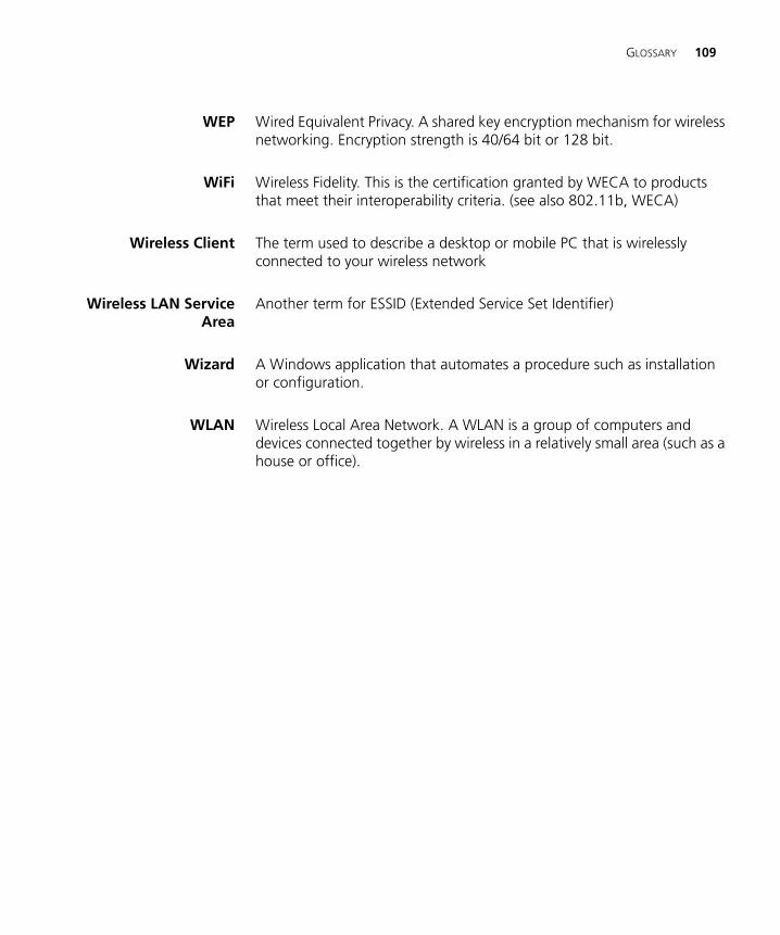
GLOSSARY 109
WEP Wired Equivalent Privacy. A shared key encryption mechanism for wireless networking. Encryption strength is 40/64 bit or 128 bit.
WiFi Wireless Fidelity. This is the certification granted by WECA to products that meet their interoperability criteria. (see also 802.11b, WECA)
Wireless Client The term used to describe a desktop or mobile PC that is wirelessly connected to your wireless network
Wireless LAN ServiceArea
Another term for ESSID (Extended Service Set Identifier)
Wizard A Windows application that automates a procedure such as installation or configuration.
WLAN Wireless Local Area Network. A WLAN is a group of computers and devices connected together by wireless in a relatively small area (such as a house or office).

110 GLOSSARY
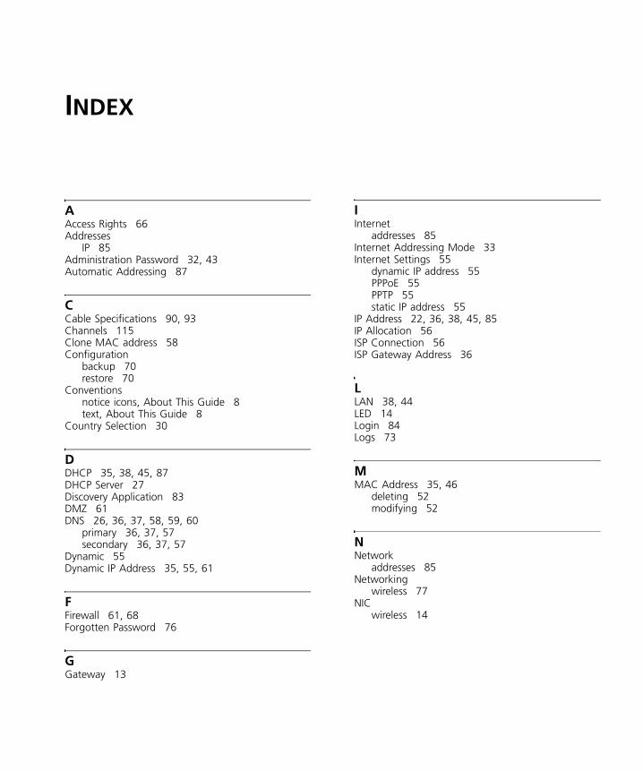
INDEX
AAccess Rights 66Addresses
IP 85Administration Password 32, 43Automatic Addressing 87
CCable Specifications 90, 93Channels 115Clone MAC address 58Configuration
backup 70restore 70
Conventionsnotice icons, About This Guide 8text, About This Guide 8
Country Selection 30
DDHCP 35, 38, 45, 87DHCP Server 27Discovery Application 83DMZ 61DNS 26, 36, 37, 58, 59, 60
primary 36, 37, 57secondary 36, 37, 57
Dynamic 55Dynamic IP Address 35, 55, 61
FFirewall 61, 68Forgotten Password 76
GGateway 13
IInternet
addresses 85Internet Addressing Mode 33Internet Settings 55
dynamic IP address 55PPPoE 55PPTP 55static IP address 55
IP Address 22, 36, 38, 45, 85IP Allocation 56ISP Connection 56ISP Gateway Address 36
LLAN 38, 44LED 14Login 84Logs 73
MMAC Address 35, 46
deleting 52modifying 52
NNetwork
addresses 85Networking
wireless 77NIC
wireless 14
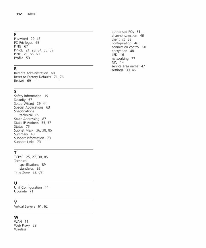
112 INDEX
PPassword 29, 43PC Privileges 65PING 67PPPoE 21, 28, 34, 55, 59PPTP 21, 55, 60Profile 53
RRemote Administration 68Reset to Factory Defaults 71, 76Restart 69
SSafety Information 19Security 67Setup Wizard 29, 44Special Applications 63Specifications
technical 89Static Addressing 87Static IP Address 55, 57Status 73Subnet Mask 36, 38, 85Summary 40Support Information 73Support Links 73
TTCP/IP 25, 27, 38, 85Technical
specifications 89standards 89
Time Zone 32, 69
UUnit Configuration 44Upgrade 71
VVirtual Servers 61, 62
WWAN 33Web Proxy 28Wireless
authorised PCs 51channel selection 46client list 53configuration 46connection control 50encryption 48LED 16networking 77NIC 14service area name 47settings 39, 46
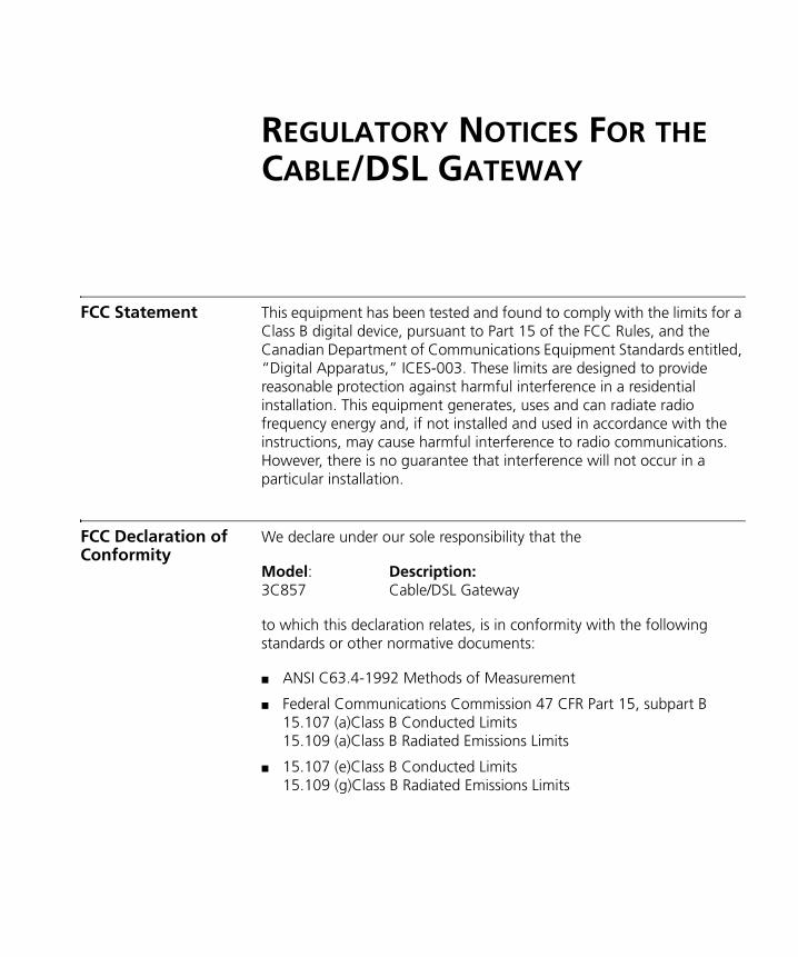
REGULATORY NOTICES FOR THE CABLE/DSL GATEWAY
FCC Statement This equipment has been tested and found to comply with the limits for a Class B digital device, pursuant to Part 15 of the FCC Rules, and the Canadian Department of Communications Equipment Standards entitled, “Digital Apparatus,” ICES-003. These limits are designed to provide reasonable protection against harmful interference in a residential installation. This equipment generates, uses and can radiate radio frequency energy and, if not installed and used in accordance with the instructions, may cause harmful interference to radio communications. However, there is no guarantee that interference will not occur in a particular installation.
FCC Declaration of Conformity
We declare under our sole responsibility that the
Model: Description:3C857 Cable/DSL Gateway
to which this declaration relates, is in conformity with the following standards or other normative documents:
■ ANSI C63.4-1992 Methods of Measurement
■ Federal Communications Commission 47 CFR Part 15, subpart B15.107 (a)Class B Conducted Limits15.109 (a)Class B Radiated Emissions Limits
■ 15.107 (e)Class B Conducted Limits15.109 (g)Class B Radiated Emissions Limits
114
CE Statement (Europe)
This product complies with the European Low Voltage Directive 73/23/EEC, EMC Directive 89/336/EEC as amended by European Directive 93/68/EEC.
CSA Statement This Class B digital apparatus meets all requirements of the Canadian Interference-Causing Equipment Regulations.
Cet appareil numérique de la classe B respecte toutes les exigences du Règlement sur le matériel brouilleur du Canada.
BSMI Statement
VCCI Statement
FCC CAUTION: To assure continued compliance, (for example, use only shielded interface cables when connecting to computer or peripheral devices) any changes or modifications not expressly approved by the party responsible for compliance could void the user’s authority to operate this equipment.
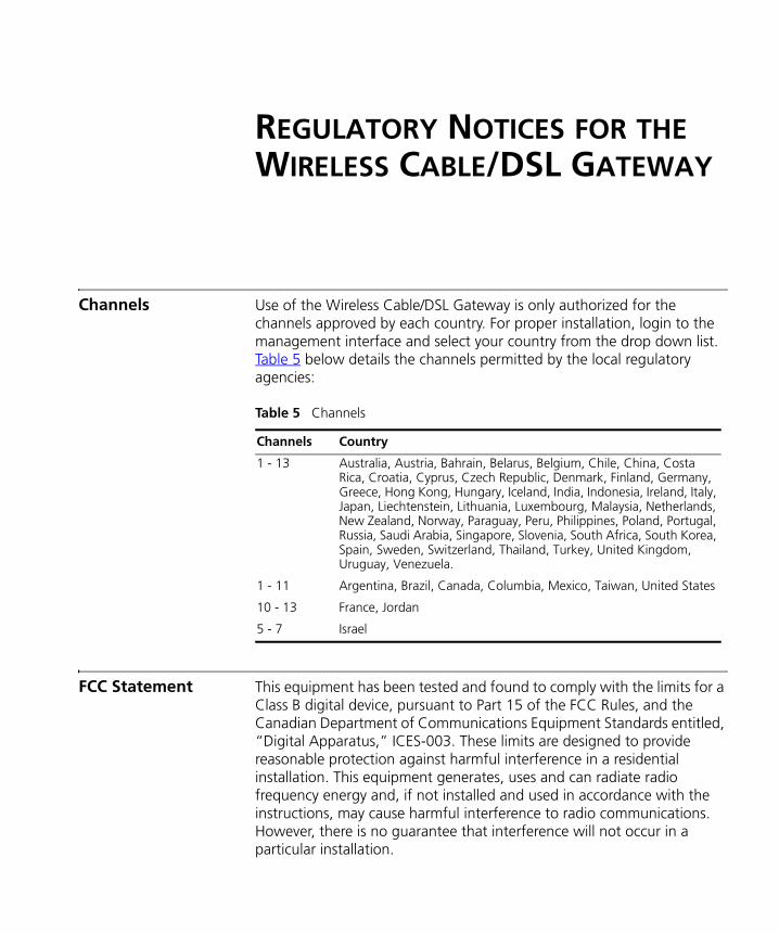
REGULATORY NOTICES FOR THE WIRELESS CABLE/DSL GATEWAY
Channels Use of the Wireless Cable/DSL Gateway is only authorized for the channels approved by each country. For proper installation, login to the management interface and select your country from the drop down list. Table 5 below details the channels permitted by the local regulatory agencies:
Table 5 Channels
FCC Statement This equipment has been tested and found to comply with the limits for a Class B digital device, pursuant to Part 15 of the FCC Rules, and the Canadian Department of Communications Equipment Standards entitled, “Digital Apparatus,” ICES-003. These limits are designed to provide reasonable protection against harmful interference in a residential installation. This equipment generates, uses and can radiate radio frequency energy and, if not installed and used in accordance with the instructions, may cause harmful interference to radio communications. However, there is no guarantee that interference will not occur in a particular installation.
Channels Country
1 - 13 Australia, Austria, Bahrain, Belarus, Belgium, Chile, China, Costa Rica, Croatia, Cyprus, Czech Republic, Denmark, Finland, Germany, Greece, Hong Kong, Hungary, Iceland, India, Indonesia, Ireland, Italy, Japan, Liechtenstein, Lithuania, Luxembourg, Malaysia, Netherlands, New Zealand, Norway, Paraguay, Peru, Philippines, Poland, Portugal, Russia, Saudi Arabia, Singapore, Slovenia, South Africa, South Korea, Spain, Sweden, Switzerland, Thailand, Turkey, United Kingdom, Uruguay, Venezuela.
1 - 11 Argentina, Brazil, Canada, Columbia, Mexico, Taiwan, United States
10 - 13 France, Jordan
5 - 7 Israel
116
Information to the User
If this equipment does cause interference to radio or television reception, which can be determined by turning the equipment off and on, the user is encouraged to try to correct the interference by one or more of the following measures:
■ Reorient the receiving antenna.
■ Relocate the equipment with respect to the receiver.
■ Move the equipment away from the receiver.
■ Plug the equipment into a different outlet so that equipment and receiver are on different branch circuits.
■ Consult the dealer or an experienced radio/television technician for help.
The user may find the following booklet prepared by the Federal Communications Commission helpful:
How to Identify and Resolve Radio-TV Interference Problems
This booklet is available from the U.S. Government Printing Office, Washington, DC 20402, Stock No. 004-000-00345-4. In order to meet FCC emissions limits, this equipment must be used only with cables which comply with IEEE 802.3.
FCC Declaration of Conformity
We declare under our sole responsibility that the
Model: Description:3CRWE52196 Wireless Cable/DSL Gateway
to which this declaration relates, is in conformity with the following standards or other normative documents:
■ ANSI C63.4-1992 Methods of Measurement
■ Federal Communications Commission 47 CFR Part 15, subpart B15.107 (a)Class B Conducted Limits15.109 (a)Class B Radiated Emissions Limits
■ 15.107 (e)Class B Conducted Limits15.109 (g)Class B Radiated Emissions Limits
117
Exposure to Radio Frequency Radiation: The radiated output power of the 3Com OfficeConnect Wireless Cable/DSL Gateway is far below the FCC radio frequency exposure limits. Nevertheless, the 3Com OfficeConnect Wireless Cable/DSL Gateway shall be used in such manner that the potential for human contact during normal operation is minimized. The distance between the antennas and the user should not be less than 20 cm.
CE Statement (Europe)
This product complies with the European Low Voltage Directive 73/23/EEC, EMC Directive 89/336/EEC as amended by European Directive 93/68/EEC and the Radio and Telecommunications Terminal Equipment Directive 99/5/EC.
CSA Statement This Class B digital apparatus meets all requirements of the Canadian Interference-Causing Equipment Regulations.
Cet appareil numérique de la classe B respecte toutes les exigences du Règlement sur le matériel brouilleur du Canada.
BSMI Statement
FCC CAUTION: To assure continued compliance, (for example, use only shielded interface cables when connecting to computer or peripheral devices) any changes or modifications not expressly approved by the party responsible for compliance could void the user’s authority to operate this equipment.
118
RF Exposure Compliance Statement (U.S.)
CAUTION: The 3Com OfficeConnect Wireless Cable/DSL Gateway has been certified as a mobile computing device as per FCC Section 2.1091. In order to comply with the FCC RF exposure requirements, the 3Com OfficeConnect Wireless Cable/DSL Gateway must only be installed with approved antennas and a minimum separation distance of 20 cm (8 in) must be maintained from the antenna to any nearby persons.
Potential RF Interference (Canada)
CAUTION: To prevent radio interference to the licensed service, this device is intended to be operated indoors and away from windows to provide maximum shielding. Equipment (or it's transmit antenna) that is installed outdoors is subject to licensing.

3Com Corporation, Corporate Headquarters,
5400 Bayfront Plaza, Santa Clara,
CA 95052-8145, USA.
To learn more about 3Com products and services,
visit our World Wide Web site at www.3com.com
All specifications are subject to change without notice.
Copyright © 2002 3Com Corporation. All rights reserved.
3Com and OfficeConnect are registered trademarks of
3Com Corporation. All other company and product names
may be trademarks of their respective companies.
DUA0085-5AAA04