offshore support vessels 2019 - ww2.eagle.org · part 5: specialized services. rules for building...
TRANSCRIPT

P a r t 5 : S p e c i a l i z e d S e r v i c e s
RULES FOR BUILDING AND CLASSING
OFFSHORE SUPPORT VESSELS 2019
PART 5 SPECIALIZED SERVICES
(Updated July 2019)
American Bureau of Shipping Incorporated by Act of Legislature of the State of New York 1862
2019 American Bureau of Shipping. All rights reserved. 1701 City Plaza Drive Spring, TX 77389 USA
ii ABS RULES FOR BUILDING AND CLASSING OFFSHORE SUPPORT VESSELS . 2019
P A R T T a b l e o f C o n t e n t s
5 Specialized Services
CONTENTS CHAPTER 1 Vessels Intended for Offshore Support Services ................................. 1
Section 1 General .................................................................................. 4 Section 2 Special Purpose ..................................................................... 8 Section 3 Domestic Service ................................................................. 14 Section 4 Strengthening for Heavy Cargoes ....................................... 15 Appendix 1 Review of Temporary Industrial Equipment and Modules ... 17
CHAPTER 2 Offshore Supply ...................................................................................... 23
Section 1 General ................................................................................ 25 Section 2 Vessel Design ...................................................................... 26 Section 3 Carriage of Limited Amounts of Hazardous and Noxious
Liquid Substances ................................................................ 33 CHAPTER 3 Anchor Handling and Towing ............................................................... 45
Section 1 General ................................................................................ 48 Section 2 Stability................................................................................. 52 Section 3 Vessel Design ...................................................................... 53 Section 4 Anchor Handling and Towing Gear ...................................... 55 Section 5 Tests .................................................................................... 60 Appendix 1 Guidelines for Static Bollard Pull Test Procedure ................ 61 Appendix 2 Intact Stability Guidelines for Anchor Handling.................... 63 Appendix 3 Intact Stability Guidelines for Towing ................................... 65
CHAPTER 4 Fire Fighting ............................................................................................ 67
Section 1 General ................................................................................ 69 Section 2 Seakeeping .......................................................................... 73 Section 3 Fire Fighting Systems, Arrangements, and Equipment ....... 74 Section 4 Structural Fire Protection ..................................................... 80 Section 5 Tests and Surveys ............................................................... 82 Appendix 1 Intact Stability Requirements for Fire Fighting Operations ...... 83
ABS RULES FOR BUILDING AND CLASSING OFFSHORE SUPPORT VESSELS . 2019 iii
CHAPTER 5 Diving and Remotely Operated Vehicles (ROVs) Support ................ 85 Section 1 General Requirements ......................................................... 87 Section 2 Seakeeping .......................................................................... 90 Section 3 Diving System Arrangement ................................................ 91 Section 4 Remotely Operated Vehicles (ROVs) and Support
System Arrangement ........................................................... 97 Section 5 Diving Support and/or ROV Capability ................................ 98 Section 6 Surveys, Inspections, and Tests ........................................ 100
CHAPTER 6 Oil Spill Recovery................................................................................. 101
Section 1 General .............................................................................. 105 Section 2 Definitions .......................................................................... 109 Section 3 Hull Construction ................................................................ 111 Section 4 Machinery Equipment and Systems .................................. 115 Section 5 Oil Spill Recovery – Capability ........................................... 125 Section 6 Oil Spill Recovery – Standby Class 2 ................................ 126 Section 7 Oil Spill Recovery – Capability Class 2 .............................. 128
CHAPTER 7 Safety Standby Rescue ....................................................................... 131
Section 1 General .............................................................................. 133 Section 2 Definitions .......................................................................... 136 Section 3 General Requirements ....................................................... 137 Section 4 Accommodations for Survivors .......................................... 139 Section 5 Rescue and Safety Equipment .......................................... 142 Section 6 Navigation and Communication Equipment....................... 145 Section 7 Surveys .............................................................................. 146
CHAPTER 8 Pipe Laying ........................................................................................... 147
Section 1 General .............................................................................. 149 Section 2 Seakeeping ........................................................................ 151 Section 3 Vessel Design and Arrangements ..................................... 153 Section 4 Pipe Laying Equipment and Systems ................................ 155 Section 5 Tests, Trials, and Surveys ................................................. 158
CHAPTER 9 Heavy LIft .............................................................................................. 159
Section 1 General .............................................................................. 161 Section 2 Seakeeping ........................................................................ 163 Section 3 Vessel Design and Equipment ........................................... 164 Section 4 Tests, Trials, and Surveys ................................................. 167 Appendix 1 Intact Stability Requirements for Vessels Equipped to
Lift ...................................................................................... 168 Appendix 2 Subsea Lifting .................................................................... 172

iv ABS RULES FOR BUILDING AND CLASSING OFFSHORE SUPPORT VESSELS . 2019
CHAPTER 10 Well Intervention ................................................................................... 173 Section 1 General .............................................................................. 176 Section 2 Well Intervention Ready ..................................................... 179 Section 3 Temporary Well Intervention Systems ............................... 185 Section 4 Permanent Well Intervention Systems ............................... 190 Section 5 Well Intervention Equipment and Systems ........................ 196 Section 6 Surveys .............................................................................. 198
CHAPTER 11 Well Stimulation .................................................................................... 199
Section 1 General .............................................................................. 201 Section 2 Seakeeping ........................................................................ 204 Section 3 Vessel Design .................................................................... 205 Section 4 Acid and Liquid Nitrogen Systems ..................................... 210 Section 5 Personnel and Fire Protection ........................................... 211 Section 6 Well Stimulation Ready ...................................................... 212 Section 7 Temporary Well Stimulation ............................................... 214
CHAPTER 12 Well Test ................................................................................................ 217
Section 1 General .............................................................................. 220 Section 2 Well Test Ready ................................................................. 223 Section 3 Installation of Temporary Well Test Systems .................... 227 Section 4 Permanent Well Test Systems .......................................... 232 Section 5 Well Test Equipment and Systems .................................... 236 Section 6 Surveys .............................................................................. 238
CHAPTER 13 Escort ..................................................................................................... 239
Section 1 General .............................................................................. 241 Section 2 Plans and Data .................................................................. 242 Section 3 Definitions .......................................................................... 243 Section 4 Intact Stability ..................................................................... 245 Section 5 Towing Gear ...................................................................... 248 Section 6 Vessel Design .................................................................... 250 Section 7 Verification of Steering Capability ...................................... 251 Section 8 Tests and Surveys ............................................................. 253
CHAPTER 14 Wind Turbine Installation, Maintenance and Repair (Wind IMR) .... 254
Section 1 General .............................................................................. 255 Section 2 Vessel Design .................................................................... 256 Section 3 Stability............................................................................... 258 Section 4 Tests, Trials, and Surveys ................................................. 259
ABS RULES FOR BUILDING AND CLASSING OFFSHORE SUPPORT VESSELS . 2019 v
CHAPTER 15 Cable Laying ......................................................................................... 260 Section 1 General .............................................................................. 262 Section 2 Seakeeping ........................................................................ 264 Section 3 Vessel Design and Arrangements ..................................... 266 Section 4 Cable Laying Equipment and Systems .............................. 267 Section 5 Tests, Trials, and Surveys ................................................. 269
CHAPTER 16 Subsea Services................................................................................... 270
Section 1 General .............................................................................. 272 Section 2 Seakeeping ........................................................................ 275 Section 3 Vessel Design and Arrangements ..................................... 277 Section 4 Cable Laying Equipment and Systems .............................. 280 Section 5 Tests, Trials, and Surveys ................................................. 281

This Page Intentionally Left Blank
ABS RULES FOR BUILDING AND CLASSING OFFSHORE SUPPORT VESSELS . 2019 1
P A R T C h a p t e r 1 : V e s s e l s I n t e n d e d f o r O f f s h o r e S u p p o r t S e r v i c e s
5 C H A P T E R 1 Vessels Intended for Offshore Support Services
CONTENTS SECTION 1 General ...................................................................................................... 4
1 Application .......................................................................................... 4 3 Definitions ........................................................................................... 4
3.1 Offshore Support Vessel ................................................................. 4 3.3 Industrial Offshore Installation ......................................................... 4 3.5 Temporary Service .......................................................................... 4
5 Classification ....................................................................................... 4 5.1 Class Notations ............................................................................... 4 5.3 Functionally Ready Notation ............................................................ 6 5.5 Change of Class Notation................................................................ 6 5.7 Optional Class Notations ................................................................. 6 5.9 Novel Features ................................................................................ 7 5.11 Selection of Class ............................................................................ 7 5.13 Administration Requirements .......................................................... 7
7 Certification of Equipment and Systems ............................................. 7 9 Submission of Data ............................................................................. 7 TABLE 1 ........................................................................................................... 5 TABLE 2 ........................................................................................................... 5 TABLE 3 ........................................................................................................... 5 TABLE 4 ........................................................................................................... 7
SECTION 2 Special Purpose ....................................................................................... 8
1 General ............................................................................................... 8 1.1 Application ....................................................................................... 8 1.3 Classification ................................................................................... 8 1.5 Scope and Limitations ..................................................................... 8 1.7 Submission of Data ......................................................................... 8
3 Definitions ........................................................................................... 9 3.1 Passenger ....................................................................................... 9 3.3 SOLAS ............................................................................................ 9 3.5 Special Personnel ........................................................................... 9 3.7 Special Purpose Ship .................................................................... 10
5 Stability.............................................................................................. 10 5.1 Intact Stability ................................................................................ 10 5.3 Subdivision and Damage Stability ................................................. 10

2 ABS RULES FOR BUILDING AND CLASSING OFFSHORE SUPPORT VESSELS . 2019
7 Machinery Installations ..................................................................... 11 7.1 Machinery Installations .................................................................. 11 7.3 Electrical Installations .................................................................... 11 7.5 Periodically Unattended Machinery Spaces ................................... 11
9 Fire Protection ................................................................................... 11 11 Life Saving Appliances ...................................................................... 12 13 Carriage of Limited Amounts of Hazardous and Noxious Liquid
Substances ....................................................................................... 12 15 Radio Communications and Safety of Navigation ............................ 12
15.1 Radio Communications .................................................................. 12 15.3 Safety of Navigation ....................................................................... 12
17 Structural Arrangements ................................................................... 13 17.1 Openings in Watertight Bulkheads ................................................. 13
SECTION 3 Domestic Service .................................................................................... 14
1 Classification ..................................................................................... 14 3 General ............................................................................................. 14
SECTION 4 Strengthening for Heavy Cargoes ........................................................ 15
1 General ............................................................................................. 15 1.1 Application ..................................................................................... 15 1.3 Classification .................................................................................. 15 1.5 Submission of Data ........................................................................ 15
3 Strengthening for Heavy Deck Cargoes ........................................... 16 3.1 Decks ............................................................................................. 16 3.3 Deck Beams and Longitudinals ..................................................... 16 3.5 Deck Girders, Transverses and Pillars........................................... 16 3.7 Side Frames and Web Frames ...................................................... 16
5 Strengthening for Heavy Liquid Cargoes .......................................... 16 5.1 Design Head .................................................................................. 16 5.3 Plain Bulkhead ............................................................................... 16 5.5 Tank-top Plating and Stiffeners ...................................................... 16 5.7 Girders and Webs .......................................................................... 16 5.9 Corrugated Deep Tank Bulkheads ................................................. 16 5.11 Higher-strength Materials ............................................................... 16
APPENDIX 1 Review of Temporary Industrial Equipment and Modules ................. 17
1 General ............................................................................................. 17 1.1 Applicability and Types of Industrial Modules ................................ 17 1.3 Background .................................................................................... 17 1.5 Analysis of Vessel Structure .......................................................... 17
3 Submission of Data ........................................................................... 18 5 Structural Review .............................................................................. 18
5.1 Arrangements ................................................................................ 18 5.3 Securing Arrangement and Securing Details ................................. 18 5.5 Weights .......................................................................................... 20

ABS RULES FOR BUILDING AND CLASSING OFFSHORE SUPPORT VESSELS . 2019 3
5.7 Deck Contact Area, Skids and Mounting Frames .......................... 20 5.9 Dynamic Loads .............................................................................. 20
7 Statutory ............................................................................................ 20 7.1 Ventilation ...................................................................................... 20 7.3 Doors, Windows and Hatches ....................................................... 21 7.5 Fire Control Plans and Lifesaving .................................................. 21
9 Electrical............................................................................................ 21 9.1 General.......................................................................................... 21
11 Mechanical and Piping ...................................................................... 21 11.1 General.......................................................................................... 21
13 Equipment Designed for Specialized Work ...................................... 21 13.1 Reels and ROV Frames ................................................................ 21
15 Stability and Tonnage ....................................................................... 22 17 Use and Occupancy of Industrial Equipment.................................... 22 FIGURE 1 Clip Welded to Equipment ...................................................... 19 FIGURE 2 Clip Not Welded to Equipment ................................................ 19

4 ABS RULES FOR BUILDING AND CLASSING OFFSHORE SUPPORT VESSELS . 2019
P A R T S e c t i o n 1 : G e n e r a l
5 C H A P T E R 1 Vessels Intended for Offshore Support Services
S E C T I O N 1 General
1 Application These Rules apply to vessels intended for support services to offshore installations.
Part 5 contains specific classification requirements for each type of vessel service as well as for specific machinery, equipment and systems, either temporarily or permanently installed on board vessels, intended for offshore support services. These requirements on hull structure, stability, equipment, system and machinery are in addition to those contained in Part 3 and Part 4 of these Rules.
3 Definitions
3.1 Offshore Support Vessel (1 July 2019) An Offshore Support Vessel is a self-propelled vessel whose regular trade is to provide services in support of exploration, exploitation, or production of offshore energy or alternative energy resources. These services may include but are not limited to: transportation of supplies and equipment, towing and anchoring of offshore structures, production well stimulation, fire fighting, handling heavy surface and subsea loads, oil spill recovery, pipeline installation, diving, safety standby, wind farm support, and subsea services.
3.3 Industrial Offshore Installation An Industrial Offshore Installation is a marine structure located at an offshore site. An installation may either be a mobile or a fixed offshore structure, located above or below the water surface, or on the seabed.
3.5 Temporary Service (2018) For well test service and well intervention, machinery and systems installed on board a vessel for less than 12 months are considered temporary.
5 Classification
5.1 Class Notations (1 July 2012) In accordance with 1-1-2/1.1 of the OSV Rules Supplement to the ABS Rules for Conditions of Classification (Part 1), the classification À A1 Offshore Support Vessel will be assigned to vessels designed for offshore support and built to the requirements in these Rules. Vessels designed and equipped to the applicable requirements for at least one specialized functional service of Part 5 and other relevant sections of these Rules will be assigned the appropriate notation as listed in 5-1-1/Table 1.
Vessels intended for several functional services covered by Part 5 of these Rules may be assigned a combination of the class notations mentioned in 5-1-1/Table 1 provided that the specific requirements for each intended service are complied with and the vessels are equipped and prepared at all times to engage in operations related to the relevant functional services.
For example, an Offshore Support Vessel capable of anchor handling, towing and supply would be assigned the classification À A1 Offshore Support Vessel (AH, Supply, TOW).
Part 5 Specialized Services Chapter 1 Vessels Intended for Offshore Support Services Section 1 General 5-1-1
ABS RULES FOR BUILDING AND CLASSING OFFSHORE SUPPORT VESSELS . 2019 5
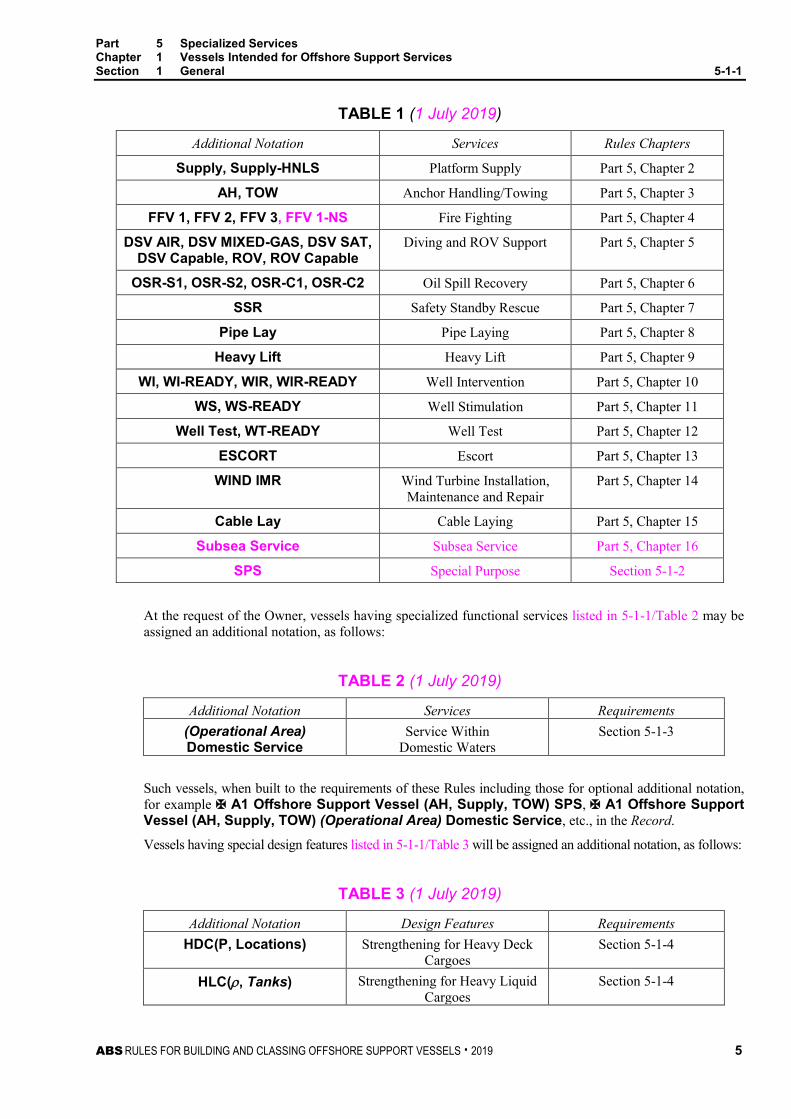
TABLE 1 (1 July 2019)
Additional Notation Services Rules Chapters
Supply, Supply-HNLS Platform Supply Part 5, Chapter 2
AH, TOW Anchor Handling/Towing Part 5, Chapter 3
FFV 1, FFV 2, FFV 3, FFV 1-NS Fire Fighting Part 5, Chapter 4
DSV AIR, DSV MIXED-GAS, DSV SAT, DSV Capable, ROV, ROV Capable
Diving and ROV Support Part 5, Chapter 5
OSR-S1, OSR-S2, OSR-C1, OSR-C2 Oil Spill Recovery Part 5, Chapter 6
SSR Safety Standby Rescue Part 5, Chapter 7
Pipe Lay Pipe Laying Part 5, Chapter 8
Heavy Lift Heavy Lift Part 5, Chapter 9
WI, WI-READY, WIR, WIR-READY Well Intervention Part 5, Chapter 10
WS, WS-READY Well Stimulation Part 5, Chapter 11
Well Test, WT-READY Well Test Part 5, Chapter 12
ESCORT Escort Part 5, Chapter 13
WIND IMR Wind Turbine Installation, Maintenance and Repair
Part 5, Chapter 14
Cable Lay Cable Laying Part 5, Chapter 15
Subsea Service Subsea Service Part 5, Chapter 16
SPS Special Purpose Section 5-1-2
At the request of the Owner, vessels having specialized functional services listed in 5-1-1/Table 2 may be assigned an additional notation, as follows:
TABLE 2 (1 July 2019)
Additional Notation Services Requirements (Operational Area) Domestic Service
Service Within Domestic Waters
Section 5-1-3
Such vessels, when built to the requirements of these Rules including those for optional additional notation, for example À A1 Offshore Support Vessel (AH, Supply, TOW) SPS, À A1 Offshore Support Vessel (AH, Supply, TOW) (Operational Area) Domestic Service, etc., in the Record.
Vessels having special design features listed in 5-1-1/Table 3 will be assigned an additional notation, as follows:
TABLE 3 (1 July 2019)
Additional Notation Design Features Requirements HDC(P, Locations) Strengthening for Heavy Deck
Cargoes Section 5-1-4
HLC(ρ, Tanks) Strengthening for Heavy Liquid Cargoes
Section 5-1-4

Part 5 Specialized Services Chapter 1 Vessels Intended for Offshore Support Services Section 1 General 5-1-1
6 ABS RULES FOR BUILDING AND CLASSING OFFSHORE SUPPORT VESSELS . 2019
Such vessels, when built to the requirements of these Rules including those for additional notation, for example À A1 Offshore Support Vessel (AH, Supply, TOW) HDC(5t/m2, main deck) and À A1 Offshore Support Vessel (AH, Supply, TOW) HLC(2.5, Tanks 3 and 5), etc., in the Record.
5.3 Functionally Ready Notation (1 July 2012) Upon Owner’s request, vessels designed and built to be “Functionally Ready” which comply with the provisions of the relevant sections of Part 5, Chapter 10, 11, or 12 for a functional service, may be assigned the applicable class notation WI-READY, WS-READY or WT-READY, respectively.
5.5 Change of Class Notation The installation or removal of the specialized equipment and systems from the vessel is to be notified to ABS in order to re-assess compliance with the classification requirements. The class notations will be modified as necessary to reflect the new status of the vessel.
5.7 Optional Class Notations (1 July 2019) Upon Owner’s request, vessels which comply with the ABS Rules and Guides listed below, may be assigned optional class notations as follows:
• CCO(TDST, TMAT), CCO-POLAR(TDST, TMAT) – vessel has been designed, built and surveyed in accordance with requirements specified in the ABS Guide for Vessels Operating in Low Temperature Environments
• CRC – compliance with the requirements for certification of cranes found in the ABS Guide for Certification of Lifting Appliances (Lifting Appliances Guide)
• DPS-1, DPS-2 or DPS-3 – the vessel is fitted with dynamic positioning equipment which complies with requirements for safety and redundancy as required by the ABS Guide for Dynamic Positioning Systems
• ENVIRO, ENVIRO+ – vessel complies with the requirements specified in ABS Guide for the Environmental Protection Notation for Vessels
• GFS, GFS(DFD), GFS(GCU) – GFS for vessel arranged to burn natural gas as fuel for propulsion or auxiliary purposes for gas fuel storage, fuel bunkering systems, fuel gas preparation rooms and fuel gas supply system arrangements are designed, constructed and tested in accordance with the Part 5C, Chapter 13 of the Steel Vessel Rules. The GFS notation may also be assigned in association with an additional notation – GFS(DFD) for dual fuel diesel engine power plant and GFS(GCU) for gas combustion unit.
• GRC(Type I or II, PS, or AS) – Vessel has an ABS Register of Offshore Access Gangway Systems permanently installed in compliance with the ABS Guide for Certification of Offshore Access Gangways
• HAB(WB), HAB+(WB), HAB++(WB) – Vessel complies with the ABS Guide for Crew Habitability on Workboats
• HELIDK or HELIDK(SRF) – helideck structure and arrangements on vessel comply with ABS Guide for the Class Notation Helicopter Decks and Facilities
• IHM – vessel is in compliance with the ABS Guide for the Inventory of Hazardous Materials
• Polar Class PC1-PC7, PC1-PC7 Enhanced, Ice Class A0, B0, C0, D0 and Ice Class 1AA, 1A, 1B and 1C – vessel complies with the ABS Rules for ice strengthening of ships navigating in first-year or multi-year ice or complies with the Finnish-Swedish Rules for navigating in the Northern Baltic in winter, respectively (see Part 6 of ABS Rules for Building and Classing Steel Vessels (Steel Vessel Rules).
• MLC-ACCOM – vessel complies with the criteria contained in the ABS Guide for Compliance with the ILO Maritime Labour Convention, 2006 Title 3 Requirements for crew accommodations and the associated ambient environmental characteristics (i.e., vibration, noise, indoor climate, and lighting)
• NBL, NBLES or NIBS – vessel complies with the relevant section of the ABS Guide for Navigation Bridge Design and Equipment/Systems
• UWILD – vessel complies with Appendix 7-A-1 “Underwater Inspections in Lieu of Drydocking Surveys” of the ABS Rules for Survey After Construction (Part 7)
Part 5 Specialized Services Chapter 1 Vessels Intended for Offshore Support Services Section 1 General 5-1-1
ABS RULES FOR BUILDING AND CLASSING OFFSHORE SUPPORT VESSELS . 2019 7
5.9 Novel Features Offshore Support Vessels, machinery and systems which contain novel features of design to which the provisions of these Rules are not directly applicable may be classed, when approved by the Committee, on the basis that these Rules, insofar as applicable, has been complied with and that special consideration has been given to the novel features, based on the best information available at that time. Risk evaluations for the justification of alternative arrangements or novel features may be applicable either to the offshore support vessel as a whole, or to individual systems, subsystems, equipment or components. The ABS Guidance Notes on Review and Approval of Novel Concepts, ABS Guidance Notes on Risk Assessment Applications for the Marine and Offshore Oil and Gas Industries, and ABS Guide for Risk Evaluations for the Classification of Marine-Related Facilities provide guidance on how to prepare a risk evaluation to demonstrate equivalency or acceptability for proposed novel features and alternative offshore support vessel design.
5.11 Selection of Class (1 July 2012) It is the responsibility of the Owner to select the class most suitable for the intended service and ensure that the vessel is operated in a safe environment with respect to the risk of fire and explosion.
5.13 Administration Requirements (1 July 2012) Requirements additional to those given in each Chapter of these Rules may be imposed by the National Administration with whom the vessel is registered or by the Administration within whose territorial jurisdiction the vessel is intended to operate.
Approval of structural fire protection, fire extinguishing equipment and/or stability of the vessel by a National Administration, in accordance with requirements equivalent to those by class, may be considered as complying with the class requirements provided such approval can be satisfactorily documented.
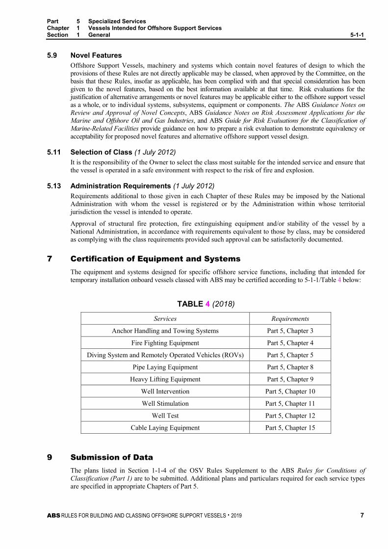
7 Certification of Equipment and Systems The equipment and systems designed for specific offshore service functions, including that intended for temporary installation onboard vessels classed with ABS may be certified according to 5-1-1/Table 4 below:
TABLE 4 (2018)
Services Requirements
Anchor Handling and Towing Systems Part 5, Chapter 3
Fire Fighting Equipment Part 5, Chapter 4
Diving System and Remotely Operated Vehicles (ROVs) Part 5, Chapter 5
Pipe Laying Equipment Part 5, Chapter 8
Heavy Lifting Equipment Part 5, Chapter 9
Well Intervention Part 5, Chapter 10
Well Stimulation Part 5, Chapter 11
Well Test Part 5, Chapter 12
Cable Laying Equipment Part 5, Chapter 15
9 Submission of Data The plans listed in Section 1-1-4 of the OSV Rules Supplement to the ABS Rules for Conditions of Classification (Part 1) are to be submitted. Additional plans and particulars required for each service types are specified in appropriate Chapters of Part 5.

8 ABS RULES FOR BUILDING AND CLASSING OFFSHORE SUPPORT VESSELS . 2019
P A R T S e c t i o n 2 : S p e c i a l P u r p o s e
5 C H A P T E R 1 Vessels Intended for Offshore Support Services
S E C T I O N 2 Special Purpose (1 July 2012)
1 General
1.1 Application (2016) The requirements in this Section apply to Offshore Support Vessels seeking to comply with the 2008 Code of Safety for Special Purpose Ships (SPS Code) adopted by the IMO Marine Safety Committee as Resolution MSC 266(84), as amended by IMO Resolution MSC.299(87).
The intent of the SPS Code is to recognize certain ships of a specialized type of service and construction, whose complement of personnel include a large number of specialized workers who are neither crew members nor passengers.
1.3 Classification Upon the Owner’s request Offshore Support Vessels that comply with the requirements in this Section and the SPS Code will be assigned the class notation SPS.
For example, an offshore support vessel engaged in pipe laying operations and complying with requirements of this Chapter and the SPS Code will be assigned the classification À A1 Offshore Support Vessel (Pipe Lay) SPS.
1.5 Scope and Limitations The SPS Code may be applied to vessels for which SOLAS certificates will be issued to reflect compliance with the SPS Code, and where ABS has been authorized to conduct such reviews by a flag Administration that is signatory to the Code.
At the request of the Owner, the SPS Code may also be the basis of review for statement of compliance or statement of fact to provide evidence of compliance or review with the SPS Code and satisfy coastal authorities in whose waters the vessel is intended to serve.
For a vessels whose flag Administration has not been a signatory to the SPS Code, the requirements of the governmental authority with regard to carriage of more than 12 special personnel are to be complied with.
Application of the SPS Code to vessels under 500 gross tonnage will be specially considered by ABS.
1.7 Submission of Data In addition to the plans listed in Section 1-1-4 of the OSV Rules Supplement to the ABS Rules for Conditions of Classification (Part 1), the following plans and particulars are to be submitted for ABS review
1.7.1 Stability and Subdivision i) General arrangement plan, with outboard profile
ii) Capacity plan or table with centers of gravity and free surface values
iii) Lines plan
iv) Tank sounding tables, if not included in the Trim and Stability Booklet.
v) Cross curves of stability, if not included in the Trim and Stability Booklet.

Part 5 Specialized Services Chapter 1 Vessels Intended for Offshore Support Services Section 2 Special Purpose 5-1-2
ABS RULES FOR BUILDING AND CLASSING OFFSHORE SUPPORT VESSELS . 2019 9
vi) List of down-flooding points, including their transverse, longitudinal and vertical locations, used in the calculation of the intact and damage stability criteria.
vii) Draft marks drawing showing the draft mark details, longitudinal locations of marks fore and aft referenced to the forward and after perpendiculars or to the nearest frames and vertical reference points. Navigational draft marks should be based on the vessel's lowest vertical projection.
viii) Intact and damage stability calculations supporting the maximum KG or minimum GM curve
ix) The Trim and Stability Booklet
1.7.2 Fire Protection and Life-Saving Appliances A fire safety and life-saving appliances plan including muster list, emergency instructions, arrangements for means of escape and ventilation, details of helicopter facilities if fitted
3 Definitions For the purposes of the SPS Code, the definitions provided in the Code shall take precedence. For terms which are used but not defined within the SPS Code, the definitions as given in SOLAS shall apply. Only definitions that need further clarification or comment with regard to their application are included hereunder.
3.1 Passenger Passenger means every person other than:
i) The master and the members of the crew or other persons employed or engaged in any capacity onboard a ship on the business of that ship; and
ii) A child under one year of age.
It is not expected that passengers on board a vessel have any special safety training or familiarity with the vessel’s safety equipment other than from the routine vessel drills.
3.3 SOLAS When in reference to the SPS Code, SOLAS is taken to mean the International Convention for the Safety of Life at Sea, 1974, as amended.
3.5 Special Personnel Special personnel means all persons who are not passengers or member of the crew or children under one year of age and who are carried onboard in connection with the special purpose of that ship or because of special work being carried out aboard that ship. Wherever in the SPS Code the number of special personnel appears as a parameter, it should include the number of passengers carried onboard which may not exceed 12.
Special personnel are expected to be able-bodied with a fair knowledge of the layout of the ship and to have received some training in safety procedures and the handling of the ship’s safety equipment before leaving port and include the following:
i). Scientists, technicians, and expeditionaries on ships engaged in research, non-commercial expeditions, and survey;
ii). Personnel engaging in training and practical marine experience to develop seafaring skills suitable for a professional career at sea
iii) Personnel who process the catch of fish, whales, or other living resources of the sea on factory ships not engaged in catching
iv) Salvage personnel on salvage ships, cable-laying personnel on cable-laying ships, seismic personnel on seismic survey ships, diving personnel on diving support ships, pipe-laying personnel on pipe layers, and crane operating personnel on floating cranes
v) Other personnel similar to those referred to above who, in the opinion of the Administration, may be referred to this group

Part 5 Specialized Services Chapter 1 Vessels Intended for Offshore Support Services Section 2 Special Purpose 5-1-2
10 ABS RULES FOR BUILDING AND CLASSING OFFSHORE SUPPORT VESSELS . 2019
3.7 Special Purpose Ship Special purpose ship means a mechanically self-propelled ship which by reason of its function carries onboard more than 12 special personnel. Where a ship carries more than 12 passengers, as defined by SOLAS, the ship should not be considered a special purpose ship as it is a passenger ship as defined by SOLAS.
5 Stability
5.1 Intact Stability 5.1.1 Application
Stability calculations and corresponding information for the Master are to be submitted for review and approval. The submission of evidence showing approval by an Administration of stability of the vessel in accordance with the SPS Code may be acceptable.
5.1.2 Stability Criteria The intact stability of special purpose ships shall comply with Section 3-3-1.
The alternative criteria given in 3-3-A1/3.5 may be used for special purpose ships of less than 100 m in length of similar design and characteristics.
5.3 Subdivision and Damage Stability 5.3.1
The subdivision and damage stability of special purpose ships should in general be in accordance with SOLAS Chapter II-1 where the ship is considered a passenger ship, and special personnel are considered passengers, with an R-value calculated in accordance with SOLAS regulation II-1/6.2.3 as follows:
i) Where the ship is certified to carry 240 persons or more, the R-value is assigned as R;
ii) Where the ship is certified to carry not more than 60 persons, the R-value is assigned as 0.8R; and
iii) For more than 60 (but not more than 240) persons, the R-value should be determined by linear interpolation between the R-values given in i) and ii) above
5.3.2 For special purpose ships to which i) applies, the requirements of SOLAS regulations II-1/8 and II-1/8-1 and of SOLAS Chapter II-1, parts B-2, B-3 and B-4 should be applied as though the ship is a passenger ship and the special personnel are passengers. However, SOLAS regulations II-1/14 and II-1/18 are not applicable.
5.3.3 For special purpose ships to which ii) or iii) applies, except as provided in 5-1-2/5.3.4 below, the provisions of SOLAS Chapter II-1, Parts B-2, B-3 and B-4 should be applied as though the ship is a cargo ship and the special personnel are crew. However, SOLAS regulations II-1/8 and II-1/8-1 need not be applied and SOLAS regulations II-1/14 and II-1/18 are not applicable.
5.3.4 All special purpose ships should comply with SOLAS regulations II-1/9, II-1/13, II-1/19, II-1/20, II-1/21 and II-1/35-1, as though the ship is a passenger ship.
5.3.5 The partial indices As, Ap and A are to be not less than 0.9R.

Part 5 Specialized Services Chapter 1 Vessels Intended for Offshore Support Services Section 2 Special Purpose 5-1-2
ABS RULES FOR BUILDING AND CLASSING OFFSHORE SUPPORT VESSELS . 2019 11
7 Machinery Installations
7.1 Machinery Installations 7.1.1 General
Under the provisions of the SPS Code, the requirements of Part C of SOLAS Chapter II-1 should be met as applicable to the type and size of the vessel. Also, the Class Rules applicable to the vessel are to be complied with.
7.1.2 Steering Gear Steering gear installations on special purpose ships should be in accordance with Regulation 29 of Part C of SOLAS Chapter II-1, except that if such ships carry not more than 240 persons, the requirements of Regulation 29.6.1.2 will apply, and for those which carry more than 240 persons, the requirements of Regulation 29.6.1.1 will apply.
7.1.3 Bilge System (2015) The bilge system on special purpose vessels is to comply with SOLAS Chapter II-1 Regulation 35-1, as applicable to passenger ships.
7.3 Electrical Installations Under the provisions of the SPS Code, the requirements of Part D of SOLAS Chapter II-1 should be met.
7.3.1 Emergency Source of Power Emergency power installations on special purpose ships carrying not more than 60 persons should be in accordance with Regulation 43 of Part D of SOLAS Chapter II-1. If such ships are greater than 50 meters in length, the requirements of Regulation 42.2.6.1 will also apply.
Emergency power installations on special purpose ships carrying more than 60 persons on board should be in accordance with Regulation 42 of Part D of SOLAS Chapter II-1.
7.3.2 Precautions Against Shock, Fire and Other Hazards of Electrical Origin Regarding hazards of electrical origin, all electrical installations should be in accordance with Regulation 45.1 through 45.10 of Part D of SOLAS Chapter II-1.
For special purpose ships carrying more than 60 persons, Regulation 45.11 of Part D of SOLAS Chapter II-1 will also apply.
7.5 Periodically Unattended Machinery Spaces (2016) Under the provisions of the SPS Code, the requirements to be complied with for periodically unattended machinery spaces are those in Part E of SOLAS Chapter II-1, Regulations 46 to 54. For special purpose ships carrying more than 240 persons, special consideration should be sought from the Administration as to whether or not their machinery spaces may be periodically unattended and whether additional requirements may be necessary to achieve a level of safety equivalent to that of normally attended machinery spaces.
9 Fire Protection Requirements of fire safety, escape, and ventilation given in Chapter II-2 of SOLAS, as well as additional requirements on helicopter facilities and dangerous cargoes, shall be applied to special purpose ships based on vessel capacity (persons on board), as follows:
Capacity Applicable Requirements of SOLAS Chapter II-2 Not more than 60 Cargo ships other than tankers 61 to 240 Passenger vessels carrying not more than 36 passengers “inclusive of
general requirements for all passenger ships” More than 240 Passenger vessels carrying more than 36 passengers “inclusive of
general requirements for all passenger ships”

Part 5 Specialized Services Chapter 1 Vessels Intended for Offshore Support Services Section 2 Special Purpose 5-1-2
12 ABS RULES FOR BUILDING AND CLASSING OFFSHORE SUPPORT VESSELS . 2019
11 Life Saving Appliances (2016)
11.1 Requirements of life-saving appliances given in Chapter III of SOLAS are to be applied to special purpose ships based on vessel capacity (persons on board), as follows:
Capacity Applicable Requirements of SOLAS Chapter III Not more than 60 Cargo ships other than tankers More than 60 Passenger vessels engaged in international voyages which are not short
international voyages
11.3 Regulations 2, 19.2.3, 21.1.2, 31.1.6, and 31.1.7 of Chapter III of SOLAS and the requirements of paragraphs 4.8 and 4.9 of the LSA Code are not applicable to special purpose ships.
11.5 Where in Chapter III of SOLAS the term “passenger” is used, it should be read to mean “special personnel” for the purpose of the SPS Code.
13 Carriage of Limited Amounts of Hazardous and Noxious Liquid Substances
13.1 The SPS Code addresses requirements for dangerous goods with reference to the IMDG Code. It is acknowledged that dangerous goods carried as ships’ stores and used onboard the ship are not subject to the provisions of the IMDG Code, while dangerous goods carried for transport and not to be used onboard become subject to requirements in the IMDG Code. However, the SPS Code advises that for dangerous goods carried for use onboard the ship, stowage and handling of such goods should be arranged with the IMDG Code taken into account as guidance and applied as best practice whenever possible. A formal safety assessment should then be conducted based on this guidance.
13.3 Offshore support vessels which may not be constructed primarily to carry bulk cargoes, but which carry hazardous or noxious liquid substances in limited quantities, will also be subject to the provisions of Section 5-2-3 of these Rules which incorporate the guidelines in IMO Resolution A.673(16) Guidelines for the Transport and Handling of Limited Amounts of Hazardous and Noxious Liquid Substances in Bulk on Offshore Support Vessel, as amended by IMO Resolutions MSC.236(82)and MEPC.158(55).
15 Radio Communications and Safety of Navigation
15.1 Radio Communications All special purpose ships should carry a valid Cargo Ship Safety Radio Certificate in compliance with Chapter IV of SOLAS.
15.3 Safety of Navigation All special purpose ships should comply with the requirements of Chapter V of SOLAS.

Part 5 Specialized Services Chapter 1 Vessels Intended for Offshore Support Services Section 2 Special Purpose 5-1-2
ABS RULES FOR BUILDING AND CLASSING OFFSHORE SUPPORT VESSELS . 2019 13
17 Structural Arrangements (2019)
17.1 Openings in Watertight Bulkheads The location and monitoring of watertight doors and bulkhead penetrations is to comply with SOLAS Chapter II-1 Regulation 13.
14 ABS RULES FOR BUILDING AND CLASSING OFFSHORE SUPPORT VESSELS . 2019
P A R T S e c t i o n 3 : D o m e s t i c S e r v i c e
5 C H A P T E R 1 Vessels Intended for Offshore Support Services
S E C T I O N 3 Domestic Service (1 July 2012)
1 Classification Vessels designed and built for domestic service operations in offshore sites in compliance with the requirements in this Section will be distinguished by the optional notation (Operational Area) Domestic Service, in accordance with 5-1-1/5.1.
3 General For a vessel intended for service in domestic waters, ABS will consider the flag Administration’s Ships Safety Regulations as an alternative in satisfying specific areas of the Rules. Where approved by the Committee for a particular service, the vessel will be classed and distinguished in the Record by the symbols À A1 Offshore Support Vessel followed by class notation, (Operational Area) Domestic Service, (e.g., À A1 Offshore Support Vessel (Supply) U.S. Domestic Service, etc.).

ABS RULES FOR BUILDING AND CLASSING OFFSHORE SUPPORT VESSELS . 2019 15
P A R T S e c t i o n 4 : S t r e n g t h e n i n g f o r H e a v y C a r g o e s
5 C H A P T E R 1 Vessels Intended for Offshore Support Services
S E C T I O N 4 Strengthening for Heavy Cargoes (1 July 2012)
1 General
1.1 Application The requirements in this Section apply to Offshore Support Vessels intended to carry heavy deck cargo exceeding 25.66 kN/m2 (2617 kgf/m2, 536 lbf/ft2) or heavy liquid cargo with specific gravity greater than 1.05.
1.3 Classification In accordance with Section 1-1-2 of the OSV Rules Supplement to the ABS Rules for Conditions of Classification (Part 1) and 5-1-1/5.1 of these Rules, the additional classification HDC(P, Locations) will be assigned to vessels designed with strengthening for carriage of heavy deck cargoes exceeding 25.66 kN/m2 (2617 kgf/m2, 536 lbf/ft2), and built to the requirements in 5-1-4/3 and other relevant sections of these Rules.
In accordance with Section 1-1-2 of the OSV Rules Supplement to the ABS Rules for Conditions of Classification (Part 1) and 5-1-1/5.1 of these Rules, the additional classification HLC(ρ, Tanks) will be assigned to vessels designed with strengthening for carriage of heavy liquid cargoes with specific gravity exceeding 1.05, and built to the requirements in 5-1-4/5 and other relevant sections of these Rules.
1.5 Submission of Data In general, in addition to the plans listed in Section 1-1-4 of the OSV Rules Supplement to the ABS Rules for Conditions of Classification (Part 1), the following plans and particulars are to be submitted.
1.5.1 Heavy Deck Cargoes • Structural details and arrangements of structures in way of cargo deck
• The design deck cargo loads in kN/m2 (kgf/m2, lbf/ft2) and locations
• Lashing arrangement of deck cargoes
1.5.2 High Density Liquid Cargoes • Tank arrangements and deep tank locations, together with their intended cargoes
• Specific gravity of highest density liquid cargoes for 100% filling of each tank
• Height of the air and overflow pipes for each tank

Part 5 Specialized Services Chapter 1 Vessels Intended for Offshore Support Services Section 4 Strengthening for Heavy Cargoes 5-1-4
16 ABS RULES FOR BUILDING AND CLASSING OFFSHORE SUPPORT VESSELS . 2019
3 Strengthening for Heavy Deck Cargoes Strengthening of deck and supporting structures in way of decks carrying heavy deck cargoes exceeding 25.66 kN/m2 (2617 kgf/m2, 536 lbf/ft2) are to be in accordance with the applicable sections in Part 3 of these Rules.
3.1 Decks The scantlings of decks are to comply with the requirements of 3-2-3/5.1, and 3-2-3/7.1 where high strength material is applied for deck.
3.3 Deck Beams and Longitudinals The scantlings of decks are to comply with the requirements of 3-2-7/3.1, and 3-2-7/7 where high strength material is applied for deck longitudinals and beams.
3.5 Deck Girders, Transverses and Pillars The scantlings of deck girders, transverses and pillars are to comply with the requirements of 3-2-8/5.3, 3-2-8/5.5, and 3-2-8/3.3 respectively. Applications of high strength material for deck girders and transverses are to meet the requirements of 3-2-8/9.
3.7 Side Frames and Web Frames The scantlings of transverse side frames, transverse tween-deck frame and web frames are to comply with the requirements of 3-2-5/3.1, 3-2-5/5.3 and 3-2-6/3.1 respectively.
5 Strengthening for Heavy Liquid Cargoes Rule required scantlings of bulkheads and other hull structures in way of cargo tanks carrying heavy liquid cargoes with specific gravity of the liquid exceeding 1.05 are to be in accordance with the applicable sections in Part 3 of these Rules.
5.1 Design Head Where the specific gravity of the liquid exceeds 1.05, the design head, h, is to be increased by the ratio of the specific gravity/1.05.
5.3 Plain Bulkhead The scantlings of bulkhead plating and stiffeners are to comply with the requirements of 3-2-10/3.1, 3-2-10/3.3, respectively, using the increased design head h in accordance with 5-1-4/5.1.
5.5 Tank-top Plating and Stiffeners The scantlings of bulkhead plate and stiffeners are to comply with the requirements of 3-2-10/3.5, using the increased design head h in accordance with 5-1-4/5.1.
5.7 Girders and Webs The scantlings of girders and webs are to comply with the requirements of 3-2-10/3.7 using the increased design head h in accordance with 5-1-4/5.1.
5.9 Corrugated Deep Tank Bulkheads The scantlings of corrugated bulkheads are to comply with the requirements of 3-2-10/3.7 using the increased design head h in accordance with 5-1-4/5.1.
5.11 Higher-strength Materials Applications of high strength material for bulkhead plate and stiffeners are to meet the requirements of 3-2-10/5.

ABS RULES FOR BUILDING AND CLASSING OFFSHORE SUPPORT VESSELS . 2019 17
P A R T A p p e n d i x 1 : R e v i e w o f T e m p o r a r y I n d u s t r i a l E q u i p m e n t a n d M o d u l e s
5 C H A P T E R 1 Vessels Intended for Offshore Support Services
A P P E N D I X 1 Review of Temporary Industrial Equipment and Modules (1 July 2016)
1 General (1 July 2019) Where a portable industrial module is installed, it is to be subjected to review by ABS as applicable in 5-1-A1/1.1 and subjected to survey in presence of and to the satisfaction of the attending Surveyor in accordance with Appendix 7-A-17 of the ABS Rules for Survey After Construction (Part 7).
Modular units may be used for various purposes, such as Workshops, Instrument Control/MCC/Battery/ Switchgear Rooms, Laboratories, Wireline Units, R.O.V. Control Room, etc. They may not be used for accommodations or living spaces.
1.1 Applicability and Types of Industrial Modules (1 July 2019) These requirements are applicable to OSVs (based on the ABS Rules for Building and Classing Offshore Support Vessels). Applicability to other vessels or offshore structures is to be determined by ABS.
Requirements of Appendix 5-1-A1 apply to portable industrial equipment modules where the forces on the cargo deck exceed the rated deck capacity, to any portable industrial equipment module which is not a standard container box or to a securing arrangement which is not covered in the vessels approved Cargo Securing Manual. Nothing in this guide is intended to permit installations of industrial equipment which would require a temporary notation. These rules do not apply to accommodation modules.
Where a container box is considered acceptable as a portable modular unit in accordance with the applicable Rules for the intended purpose, the container is to be confirmed as being certified to a recognized standard.
1.3 Background (1 July 2019) The installation of temporary industrial equipment, industrial spaces, and workshops has become increasingly prevalent in recent years. Irrespective of the amount of time that portable modules are installed onboard, the potential risks to personnel within and around these modules is of concern and therefore it is imperative that details are reviewed as required.
1.5 Analysis of Vessel Structure (2019) Where isolated deck cargo is carried on deck the vessel scantlings are to comply with Section 5-1-4. The vessels structure will be analyzed using standard accelerations applied from the IMO Code of Safe Practice for Cargo Stowage and Securing (CSS Code). The accelerated loads will be decoupled and applied into the deck supporting members via the contact points of the cargo. The resulting stresses in deck members are not to exceed those values found in 5-2-2/1.3.
If a vendor provides drawings or documents of design loads or forces, then these design loads are to include accelerations in the transverse, longitudinal and vertical directions due to vessel motions of roll, pitch and heave.
A load which exceeds the rated deck capacity is one who’s static weight divided by its contact area to the deck is in excess of what ABS has approved as the rated deck capacity.

Part 5 Specialized Services Chapter 1 Vessels Intended for Offshore Support Services Appendix 1 Review of Temporary Industrial Equipment and Modules 5-1-A1
18 ABS RULES FOR BUILDING AND CLASSING OFFSHORE SUPPORT VESSELS . 2019
3 Submission of Data (2019) In general, for the installation of industrial equipment and modules, the list of plans in 5-2-1/7 applies. When a vessel is carrying independent tanks on deck which contain Hazardous and Noxious Liquid Substances, as defined in Section 5-2-3 of the Rules, International Code for the Construction and Equipment of Ships Carrying Dangerous Chemicals in Bulk (IBC Code), IMO Resolution A.673 (16) and IEC 60092-502, then the list of plans in 5-2-3/7 applies.
Some flag Administrations may have specific requirements on certification dates and construction standards of industrial modules that are manned. When these requirements are applicable, all required documentation should be submitted to ABS.
5 Structural Review
5.1 Arrangements A revised General Arrangement drawing is to be submitted for the vessel whenever industrial equipment is installed on deck. This submittal will be kept available for reference by ABS for the duration of the installation. The General Arrangement is to show the exact location of each piece of industrial equipment and is to be furnished to ABS at the start of the project. If the location of equipment changes, then a new arrangement is to be submitted to ABS. At the completion of a project or when all industrial equipment has been removed, a notice is to be furnished to ABS. At this time a clean General Arrangement is not required, provided that it has not changed from the revision which previously reviewed by ABS prior to the installation of the equipment.
Stacked arrangements of container boxes as modular units require design review by ABS, and are to be surveyed accordingly.
5.3 Securing Arrangement and Securing Details Where securing devices used are outside the scope of the vessel’s Cargo Securing Manual, the equipment exceeds rated deck capacity, or a Cargo Securing Manual has not been approved for the vessel, details of securing devices are to be reviewed by ABS. These details may be provided either on a separate drawing or on the General Arrangement. All securing details are to be shown. If the equipment does not exceed the deck capacity and the securing devices are included in the approved Cargo Securing Manual, then the securing is at the discretion of the vessel’s crew in accordance with the vessel’s Cargo Securing Manual.
5.3.1 Plate Clips A clip is a piece of vertical plate where the horizontal edge is welded to the deck and likewise the vertical edge is welded to the piece of equipment or skid, see 5-1-A1/Figure 1.
In some cases, a vendor may request securing devices, including plate clips, not be welded to their equipment, as shown in 5-1-A1/Figure 2. In this case, the clip may be slotted into a corner casting or fit tightly around an accessible edge. In this case effectiveness of the clips is to be reduced and the weld at the deck sized to take appropriate loads. If plate clips are the only means of securing, then clips should ideally be provided in both the transverse and longitudinal directions. These clips, in their quantity, size, and welds, are to be able to resist the forces of sliding, tipping, and vertical accelerations in their effective direction, and calculations should be performed to confirm this for both shear and weld strength.
A plate clip is generally only effective along the plane to which it is parallel. Additional calculations may be necessary to check the bending strength adequacy of the clip based on the clip design and the proposed arrangement.
Required details for plate clips are:
• Plate thickness
• Weld size and details
• Dimensions of the clip

Part 5 Specialized Services Chapter 1 Vessels Intended for Offshore Support Services Appendix 1 Review of Temporary Industrial Equipment and Modules 5-1-A1
ABS RULES FOR BUILDING AND CLASSING OFFSHORE SUPPORT VESSELS . 2019 19
FIGURE 1 Clip Welded to Equipment (1 July 2016)
Industrial Equipment
Welded to Equipment
Plate Clip
Main Deck
Welded to Deck
FIGURE 2 Clip Not Welded to Equipment (1 July 2016)
Industrial Equipment Plate Clip
Main Deck
Welded to Deck
Clip Slotted in Corner Casting or Similar
5.3.2 Lashings including Chain and Wire Rope All chains, wire ropes, turnbuckles and all other pieces of lashing equipment being used are to comply with those approved in the vessel’s Cargo Securing Manual, if one is provided. Securing devices not in the cargo securing manual may be used if details of them are provided.
When lashings are used, they are to be able to resist the forces of sliding, tipping, and vertical accelerations in their effective direction.
The effective direction of a lashing is defined in the IMO Code of Safe Practice for Cargo Stowage and Securing (CSS Code) ANNEX 13 which provides reductions in working loads of devices based on the angles formed between the deck and cargo.
Required details for lashings are:
• Securing point on deck
• Securing point on the equipment
• Angle of the lash with respect to the deck and respect to the centerline of the vessel

Part 5 Specialized Services Chapter 1 Vessels Intended for Offshore Support Services Appendix 1 Review of Temporary Industrial Equipment and Modules 5-1-A1
20 ABS RULES FOR BUILDING AND CLASSING OFFSHORE SUPPORT VESSELS . 2019
• Material and type of lashing (i.e., Chain, wire rope, turnbuckle, shackles, etc.)
• Safe Working Load of lashings
5.3.3 ISO Fittings ISO fitting means, any deck socket, twist lock, deck casting, or securing device which is ISO or type approved.
Where ISO fittings are used, cut sheets or manufacturer specifications of all parts are to be provided to ABS; or at a minimum the manufacturer and model are to be noted on the arrangement, securing drawing or furnished to ABS.
5.5 Weights A static weight is to be provided to ABS for every piece of industrial equipment which exceeds the rated deck capacity. This weight should be noted on the drawing or provided in a separate document.
All weights are subject to motion based accelerations per the IMO Code of Safe Practice for Cargo Stowage and Securing (CSS Code). The CSS Code provides not only vertical accelerations but also transverse and longitudinal sliding and tipping forces.
If the vendor or manufacturer of the equipment provides design loads, these loads are to incorporate accelerations consistent with the CSS Code.
5.7 Deck Contact Area, Skids and Mounting Frames For all industrial equipment and cargo, the contact area to the deck is to be specified.
For equipment which sits on a skid or frame, details of the skid are to be provided, including identification of members and how the skid is secured to the deck as well as how the piece of equipment is secured to the skid or frame.
If the piece of equipment has integral contact points which are part of the design, then these contact areas are to be noted on the arrangement drawing. Additionally, vendor drawings, documents and details pertaining to the installation of industrial equipment are to be furnished to ABS if release is authorized by the vendor. Additional details and information may be requested to verify contact area.
Structural credit will not be given to a skid or frame on which industrial equipment is mounted. However, loads will be reasonably distributed along the contact area and appropriately applied to the deck and/or vessel structure.
5.9 Dynamic Loads Dynamic loads are to be provided for any piece of equipment such as a cable reel, ROV frame, or any other piece of equipment which will deploy anything over the vessel side.
If the manufacture of such equipment provided design loads, then this information is to be furnished to ABS. These design loads are to include dynamic forces for the equipment when it is in use. Generally, dynamic loads will exceed the accelerations applied to the static weight from the IMO Code of Safe Practice for Cargo Stowage and Securing (CSS Code). Therefore, these loads are to be applied to supporting members appropriately. If dynamic forces are included in the design loads, it is at the discretion of ABS to determine whether the dynamic forces are sufficient per applicable rules and regulations.
7 Statutory
7.1 Ventilation When any piece of equipment or independent tank is installed on deck, ventilation openings and their proximity to hazards and cargoes are to comply with Section 5-2-3 of the Rules as well as the applicable regulations, including the International Code for the Construction and Equipment of Ships Carrying Dangerous Chemicals in Bulk (IBC Code) and IMO Resolution A.673 (16) and IEC 60092-502. When a piece of equipment or independent tank is installed on deck and modification is necessary to meet the applicable requirements, then a revised ventilation arrangement is to be submitted to ABS for review.
Part 5 Specialized Services Chapter 1 Vessels Intended for Offshore Support Services Appendix 1 Review of Temporary Industrial Equipment and Modules 5-1-A1
ABS RULES FOR BUILDING AND CLASSING OFFSHORE SUPPORT VESSELS . 2019 21
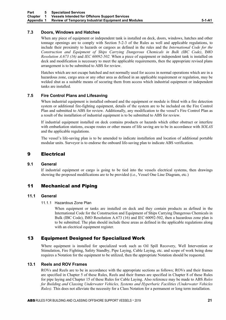
7.3 Doors, Windows and Hatches When any piece of equipment or independent tank is installed on deck, doors, windows, hatches and other tonnage openings are to comply with Section 5-2-3 of the Rules as well and applicable regulations, to include their proximity to hazards or cargoes as defined in the rules and the International Code for the Construction and Equipment of Ships Carrying Dangerous Chemicals in Bulk (IBC Code), IMO Resolution A.673 (16) and IEC 60092-502. When a piece of equipment or independent tank is installed on deck and modification is necessary to meet the applicable requirements, then the appropriate revised plans arrangement is to be submitted to ABS for review.
Hatches which are not escape hatched and not normally used for access in normal operations which are in a hazardous zone, cargo area or any other area as defined in an applicable requirement or regulation, may be welded shut as a suitable means of securing them from access which industrial equipment or independent tanks are installed.
7.5 Fire Control Plans and Lifesaving When industrial equipment is installed onboard and the equipment or module is fitted with a fire detection system or additional fire-fighting equipment, details of the system are to be included on the Fire Control Plan and submitted to ABS for review. Additionally, any modification to the vessel’s Fire Control Plan as a result of the installation of industrial equipment is to be submitted to ABS for review.
If industrial equipment installed on deck contains products or hazards which either obstruct or interfere with embarkation stations, escape routes or other means of life saving are to be in accordance with SOLAS and the applicable regulations.
The vessel’s life-saving plan is to be amended to indicate installation and location of additional portable modular units. Surveyor is to endorse the onboard life-saving plan to indicate ABS verification.
9 Electrical
9.1 General If industrial equipment or cargo is going to be tied into the vessels electrical systems, then drawings showing the proposed modifications are to be provided (i.e., Vessel One Line Diagram, etc.)
11 Mechanical and Piping
11.1 General 11.1.1 Hazardous Zone Plan
When equipment or tanks are installed on deck and they contain products as defined in the International Code for the Construction and Equipment of Ships Carrying Dangerous Chemicals in Bulk (IBC Code), IMO Resolution A.673 (16) and IEC 60092-502, then a hazardous zone plan is to be submitted. The plan should include these areas as defined in the applicable regulations along with an electrical equipment register.
13 Equipment Designed for Specialized Work Where equipment is installed for specialized work such as Oil Spill Recovery, Well Intervention or Stimulation, Fire Fighting, Safety Standby, Pipe Laying, Cable Laying, etc. and scope of work being done requires a Notation for the equipment to be utilized, then the appropriate Notation should be requested.
13.1 Reels and ROV Frames ROVs and Reels are to be in accordance with the appropriate sections as follows; ROVs and their frames are specified in Chapter 5 of these Rules, Reels and their frames are specified in Chapter 8 of these Rules for pipe laying and Chapter 15 of these Rules for Cable Laying. Also reference may be made to ABS Rules for Building and Classing Underwater Vehicles, Systems and Hyperbaric Facilities (Underwater Vehicles Rules). This does not alleviate the necessity for a Class Notation for a permanent or long term installation.

Part 5 Specialized Services Chapter 1 Vessels Intended for Offshore Support Services Appendix 1 Review of Temporary Industrial Equipment and Modules 5-1-A1
22 ABS RULES FOR BUILDING AND CLASSING OFFSHORE SUPPORT VESSELS . 2019
This equipment is not only subject to accelerated loads but also dynamics loads during operation.
Typically, this type of equipment is designed to a maximum operating condition and therefore dynamic loads are likely incorporated in the vendor design. ABS understands that for confidentiality reasons, vendors may not provide design specifications including dynamic loads. In this case, if a vendor only provides uncoupled loads or reactions at contact areas, then ABS may request confirmation that dynamic loads were applied to the vendor supplied loads.
If a vendor does not provide dynamic loads and the uncoupled loads and reactions do not include dynamic loading, then it is the shipyards responsibility to specify maximum operating sea state and dynamics loads which will affect the equipment.
15 Stability and Tonnage Whenever industrial equipment is installed the ABS Tonnage and Load Line, and Stability Departments should be contacted for any implications which may be a result of the installation of the equipment.
17 Use and Occupancy of Industrial Equipment Industrial Equipment and modules are to not be occupied in heavy weather conditions. For information about modules in which living accommodations are provided, please see the ABS Guide for Portable Accommodation Modules.
ABS may place other restrictions and conditions on the use and occupancy of the industrial equipment on a case-by-case basis and will take into account the purpose of the equipment and operating conditions.
P A R T C h a p t e r 2 : O f f s h o r e S u p p l y
5 C H A P T E R 2 Offshore Supply
CONTENTS SECTION 1 General .................................................................................................... 25
1 Application ........................................................................................ 25 3 Scope ................................................................................................ 25 5 Classification ..................................................................................... 25 7 Submission of Data ........................................................................... 25
SECTION 2 Vessel Design ......................................................................................... 26
1 Cargo Deck ....................................................................................... 26 1.1 Deck Arrangement ........................................................................ 26 1.3 Reinforcement Against Heavy Cargoes ........................................ 26 1.5 Deck Covering ............................................................................... 26 1.7 Securing Deck Cargo .................................................................... 26 1.9 Cargo Rail ..................................................................................... 27 1.11 Other Requirements ...................................................................... 27
2 Side Structures ................................................................................. 27 3 Cargo Tanks ..................................................................................... 28
3.1 Liquid Cargo Tanks ....................................................................... 28 3.3 Dry Cargo Tanks ........................................................................... 30 3.5 Multi-Functional Cargo Tanks ........................................................ 30 3.7 Spill Coaming ................................................................................ 30
5 Cargo Piping Systems ...................................................................... 30 5.1 Liquid Cargoes .............................................................................. 31 5.3 Dry Cargo Piping Systems ............................................................ 31 5.5 Integrated Cargo Tank Piping System ........................................... 31 5.7 Cargo Transfer Import and Export System .................................... 32
7 Machinery Installations ..................................................................... 32 7.1 Steering Gear ................................................................................ 32 7.3 Engine Exhaust Outlets ................................................................. 32
SECTION 3 Carriage of Limited Amounts of Hazardous and Noxious Liquid
Substances ............................................................................................. 33 1 General ............................................................................................. 33
1.1 Application ..................................................................................... 33 1.3 Scope ............................................................................................ 33
3 Classification ..................................................................................... 34 5 Definitions ......................................................................................... 34
5.1 Cargo Area .................................................................................... 34 5.3 Deadweight ................................................................................... 34
ABS RULES FOR BUILDING AND CLASSING OFFSHORE SUPPORT VESSELS . 2019 23

5.5 Lightweight ..................................................................................... 34 5.7 Hazardous Substance.................................................................... 34 5.9 Pollution Hazard Only Substance .................................................. 35 5.11 Safety Hazard Substance .............................................................. 35 5.13 Flammable Liquid .......................................................................... 35
7 Submission of Data ........................................................................... 35 9 Vessel Design ................................................................................... 36
9.1 Cargo Tank Location...................................................................... 36 9.3 Cargo Segregation ......................................................................... 36 9.5 Accommodation, Service and Machinery Spaces and Control
Stations .......................................................................................... 37 9.7 Access to Spaces in the Cargo Area ............................................. 37 9.9 Cargo Tank Construction ............................................................... 38 9.11 Materials of Construction ............................................................... 39 9.13 Cargo Tank Vent Systems ............................................................. 39 9.15 Cargo Transfer ............................................................................... 40 9.17 Electrical Installations .................................................................... 40 9.19 Fire-Fighting Requirements ........................................................... 40 9.21 Acid Spill Protection ....................................................................... 41 9.23 Ventilation of Spaces in the Cargo Area ........................................ 41 9.25 Vapor Detection ............................................................................. 42 9.27 Special Requirements – General ................................................... 42 9.29 Special Requirements for the Carriage of Liquefied Gases ........... 42 9.31 Gauging and Level Detection ......................................................... 42 9.33 Emergency Remote Shutdown ...................................................... 43
11 Pollution Requirements ..................................................................... 43 13 Personnel Protection ......................................................................... 43
13.1 Decontamination Showers and Eyewashes ................................... 43 13.3 Protective and Safety Equipment ................................................... 43
15 Operational Guidance ....................................................................... 43 TABLE 1 Permitted Products .................................................................. 44 FIGURE 1 Access Openings .................................................................... 38
24 ABS RULES FOR BUILDING AND CLASSING OFFSHORE SUPPORT VESSELS . 2019

P A R T S e c t i o n 1 : G e n e r a l
5 C H A P T E R 2 Offshore Supply
S E C T I O N 1 General
1 Application The requirements in this Chapter apply to vessels intended for unrestricted service which are primarily engaged in the transport of stores, materials, equipment and/or personnel (excluding crew boats) to, from and between offshore installations.
3 Scope Section 5-2-2 addresses the safety aspects related to offshore supply vessels for carrying deck cargoes, dry and liquid cargoes including flammable cargoes having a flashpoint (closed cup test) above 60°C (140°F), such as fuel oil, base oil and oil-based liquid mud. The provisions for carrying Hazardous and Noxious Liquid Substances (HNLS) and dangerous goods covered by the International Maritime Dangerous Goods (IMDG) Code are provided in Section 5-2-3.
5 Classification In accordance with Section 1-1-2 of the OSV Rules Supplement to the ABS Rules for Conditions of Classification (Part 1) and 5-1-1/5.1 of these Rules, the classification À A1 Offshore Support Vessel (Supply) is to be assigned to vessels designed primarily for transport service as defined in 5-2-1/1, and built to the requirements of this Chapter and other relevant sections of these Rules.
7 Submission of Data In general, in addition to the plans listed in Section 1-1-4 of the OSV Rules Supplement to the ABS Rules for Conditions of Classification (Part 1), the following plans and particulars are to be submitted.
• Information regarding loading arrangement of deck cargoes, weights and their centers of gravity
• Structural details and arrangements of structures in way of cargo deck
• Lashing arrangement of deck cargoes
• Details of integral liquid cargo tanks including vents and/or overflows height and location
• Details of independent liquid and/or dry cargo tanks
• Details of independent tank supports and fastening arrangements
• Piping diagrams of liquid cargo transfer systems
• Piping diagrams of dry bulk cargo transfer systems
• Ventilation diagrams of liquid cargoes
• Arrangement in dry cargo compartment
• Stability data and calculations
ABS RULES FOR BUILDING AND CLASSING OFFSHORE SUPPORT VESSELS . 2019 25

P A R T S e c t i o n 2 : V e s s e l D e s i g n
5 C H A P T E R 2 Offshore Supply
S E C T I O N 2 Vessel Design
1 Cargo Deck
1.1 Deck Arrangement Safe havens and escape routes for personnel from the cargo deck are to be properly marked and kept clear at all times. A cargo rail (crash barrier) fitted along each side of the deck and/or aft may be the method of providing a safe haven.
The vessel is to be equipped with a sufficient quantity and types of lashing and securing materials for the safe operation of the vessel, and comply with the Code of Safe Practice for Cargo Stowage and Securing (CSS) Code (IMO resolution A.714(17)), IMO/ILO/UN/ECE Guidelines for Packing of Cargo Transport Units (CTUs),(MSC/Circ.787)
1.3 Reinforcement Against Heavy Cargoes Where heavy cargo is carried on deck, means such as steel cradle or steel or wooden dunnage is to be provided so that the cargo weight is uniformly distributed into deck structures. The stresses in deck members are not to exceed the following values. Members may be considered fixed-ended provided they are continuous over the adjacent space or are attached to a bulkhead stiffener or frame by effective brackets.
σ N/mm2 (tf/cm2, ltf/in2)
τ N/mm2 (tf/cm2, ltf/in2)
Longitudinal Beam/Girder: Transverse Beam/Web:
124 (1.26, 8.0) 140 (1.42, 9.0)
69 (0.70, 4.4) 85 (0.87, 5.5)
1.5 Deck Covering Knot free wooden sheathings, in form of planks not attached permanently to the plating, are to be provided on cargo decks to protect steel deck plate from mechanical damage and/or rubbing. Thickness of wooden sheathing is to be at least 50 mm (2 inches). The deck plating under the wooden planks is to be protected by heavy duty paint or equivalent coating. Adequate arrangements allowing drainage from beneath the wooden sheathing are to be provided.
1.7 Securing Deck Cargo Pad eyes for cargo securing and/or moving are to be welded directly to the deck plating; no doublers are allowed. The pad eyes are to be adequately supported by approved deck reinforcement. Dismountable pad eyes and stanchions are to have firm attachments to the deck sockets or holdings. All pad eyes are to be permanently marked with bead welded SWL values.
26 ABS RULES FOR BUILDING AND CLASSING OFFSHORE SUPPORT VESSELS . 2019

Part 5 Specialized Services Chapter 2 Offshore Supply Section 2 Vessel Design 5-2-2
1.9 Cargo Rail (2014) Where cargo rails are fitted on cargo deck, they are to have freeing ports allowing quick drainage of water from the deck. Scantlings of cargo rail are to be not less than following:
i) Rail:
SM = 0.858bHs2 cm3 SM = 0.000452bHs2 in3
where
b = breadth of cargo deck, between cargo rails, in m (ft)
s = spacing of cargo rail stanchion, in m (ft)
H = mean height of cargo, in m (ft), to be submitted as the basis for verifying that cargo rail structures provide sufficient strength to withstand the worst anticipated deck cargo loads
ii) Standing alone stanchion in way of deck attachment:
SM = 10.14bhHs cm3 SM = 0.00534bhHs in3
where
b = breadth of cargo deck, between cargo rails, in m (ft)
s = spacing of cargo rail stanchion, in m (ft)
h = height of cargo rail, in m (ft)
H = mean height of cargo, in m (ft), as defined in 5-2-2/1.9i)
iii) Stanchion as part of the frame:
The stresses in the single stanchion under a concentrated load of 0.155bHs tons (9.75bHs lbs), applied horizontally are not to exceed the following:
Normal Stress = 0.7Y
Shear Stress = 0.4Y
where
Y = specified minimum tensile yield strength or yield point.
b, H, and s are as defined in 5-2-2/1.9i)
Alternatively, the cargo rails and stanchions design using the direct calculation or FE analysis based on the design loads and load distribution may be acceptable providing that calculations are to be submitted and subject to review for comply with the strength requirements in 5-2-2/1.9iii) or Section 3-2-20.
1.11 Other Requirements The Code of Safe Practice for Cargo Stowage and Securing (CSS Code (IMO resolution A.714(17)), IMO/ILO/UN/ECE Guidelines for Packing of Cargo Transport Units (CTUs (MSC/Circ.787) are also to be complied with.
2 Side Structures (2014) For vessels subject to impact loads during routine operations, see 3-2-2/3.11, 3-2-5/11 and 3-2-6/11.
ABS RULES FOR BUILDING AND CLASSING OFFSHORE SUPPORT VESSELS . 2019 27
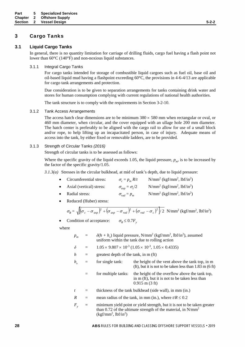
Part 5 Specialized Services Chapter 2 Offshore Supply Section 2 Vessel Design 5-2-2
3 Cargo Tanks
3.1 Liquid Cargo Tanks In general, there is no quantity limitation for carriage of drilling fluids, cargo fuel having a flash point not lower than 60°C (140°F) and non-noxious liquid substances.
3.1.1 Integral Cargo Tanks For cargo tanks intended for storage of combustible liquid cargoes such as fuel oil, base oil and oil-based liquid mud having a flashpoint exceeding 60°C, the provisions in 4-6-4/13 are applicable for cargo tank arrangements and protection.
Due consideration is to be given to separation arrangements for tanks containing drink water and stores for human consumption complying with current regulations of national health authorities.
The tank structure is to comply with the requirements in Section 3-2-10.
3.1.2 Tank Access Arrangements The access hatch clear dimensions are to be minimum 380 × 580 mm when rectangular or oval, or 460 mm diameter, when circular, and the cover equipped with an ullage hole 200 mm diameter. The hatch center is preferably to be aligned with the cargo rail to allow for use of a small block and/or rope, to help lifting up an incapacitated person, in case of injury. Adequate means of access into the tank, by either fixed or removable ladders, are to be provided.
3.1.3 Strength of Circular Tanks (2016) Strength of circular tanks is to be assessed as follows:
Where the specific gravity of the liquid exceeds 1.05, the liquid pressure, pm, is to be increased by the factor of the specific gravity/1.05.
3.1.3(a) Stresses in the circular bulkhead, at mid of tank’s depth, due to liquid pressure:
• Circumferential stress: σc = pm R/t N/mm2 (kgf/mm2, lbf/in2)
• Axial (vertical) stress: σaxp = σc/2 N/mm2 (kgf/mm2, lbf/in2)
• Radial stress: σrad = pm N/mm2 (kgf/mm2, lbf/in2)
• Reduced (Huber) stress:
σR = ( ) ( ) ( )[ ] 2/222cradradaxpaxpc σσσσσσ −+−+− N/mm2 (kgf/mm2, lbf/in2)
• Condition of acceptance: σR ≤ 0.7Fy
where
pm = δ(h + hv) liquid pressure, N/mm2 (kgf/mm2, lbf/in2), assumed uniform within the tank due to rolling action
δ = 1.05 × 9.807 × 10-3 (1.05 × 10⁻³, 1.05 × 0.4335)
h = greatest depth of the tank, in m (ft)
hv = for single tank: the height of the vent above the tank top, in m (ft), but it is not to be taken less than 1.83 m (6 ft)
= for multiple tanks: the height of the overflow above the tank top, in m (ft), but it is not to be taken less than 0.915 m (3 ft)
t = thickness of the tank bulkhead (side wall), in mm (in.)
R = mean radius of the tank, in mm (in.), where t/R ≤ 0.2
Fy = minimum yield point or yield strength, but it is not to be taken greater than 0.72 of the ultimate strength of the material, in N/mm2 (kgf/mm2, lbf/in2)
28 ABS RULES FOR BUILDING AND CLASSING OFFSHORE SUPPORT VESSELS . 2019

Part 5 Specialized Services Chapter 2 Offshore Supply Section 2 Vessel Design 5-2-2
3.1.3(b) Overall buckling check on the cross section of axially loaded compression members, when the largest effective slenderness ratio K/r on any unbraced bulkhead segment is less than below Cc
Cc = yFE22π
where
K = 0.5 for both ends constrained
= longest unsupported part of the tank’s depth, in mm (in.)
r = ( )AI / , radius of gyration, in mm (in.)
I = moment of inertia of the bulkhead’s horizontal section, in mm4 (in4)
A = sectional area of the bulkhead’s horizontal section, in mm2 (in2)
E = modulus of elasticity, 2.06 × 10⁵ N/mm2 (2.1 × 10⁴ kgf/mm2, 30 × 106 lbf/in2) for steel
Fy = minimum yield point or yield strength, but it is not to be taken greater than 0.72 of the ultimate strength of the steel, in N/mm2 (kgf/mm2, lbf/in2)
i) Allowable axial compressive stress Fa, in N/mm2 (kgf/mm2, lbf/in2)
Fa =
( )
( ) ( )3
3
2
2
8/
8/3
35
2/1
cc
yc
CrK
CrK
FC
rKQ
−+
−
where
Q = 0.75
ii) Compressive stress due to deck cargo
σaxc = kabp/A N/mm2 (kgf/mm2, lbf/in2)
where
k = 2.0; static pitch dynamic factor
a = length of the part of deck supported by the tank, in m (ft)
b = breadth of the part of deck supported by the tank, in m (ft)
p = uniform deck cargo load, in N/mm2 (kgf/mm2, lbf/in2)
A = sectional area of the bulkhead’s ring, in m2 (ft2)
iii) Total compressive stress: σax = (σaxp + σaxc), in N/mm2 (kgf/mm2, lbf/in2)
Condition of acceptance: σax ≤ Fa
3.1.3(c) Local buckling check in case of un-stiffened or ring-stiffened cylinder made of steel.
Local buckling is to be investigated when D/t > E/4.5Fy
where
D = mean diameter of the cylindrical bulkhead, in mm (in.)
t, E, and Fy are as in 5-2-2/3.1.3(a) and 5-2-2/3.1.3(b) above.
ABS RULES FOR BUILDING AND CLASSING OFFSHORE SUPPORT VESSELS . 2019 29

Part 5 Specialized Services Chapter 2 Offshore Supply Section 2 Vessel Design 5-2-2
i) Classical compressive buckling stress for an imperfect cylinder, in N/mm2 (kgf/mm2, lbf/in2)
σExR = 121E(1750t/R – 1) ×10-6
on condition that 0.952/Rt ≥ 20 (for steel)
ii) Critical local buckling stress, in N/mm2 (kgf/mm2, lbf/in2)
σCxR = Fy(1 – 0.24Fy/σExR)
on condition that σExR > 0.6Fy (for steel)
Condition of acceptance: σR ≤ σCxR
where Fy, E, R, t, and are as in 5-2-2/3.1.3(a) and 5-2-2/3.1.3(b) above.
3.1.4 Independent Cargo Tanks In addition to the applicable requirements in Part 3 and Part 4, supports of independent cargo tanks are to be provided such that the stresses in supporting members and hull structures are within the allowable limits specified in 5-2-2/1.3 above.
3.3 Dry Cargo Tanks 3.3.1 General
Where cargo tanks for dry cement or dry mud (pulverized materials such as barite, bentonite, etc.) are fitted, these cargo tanks are to be separated from Category A machinery spaces, accommodation spaces and service spaces by watertight bulkheads and decks.
3.3.2 Cargo Tank Design Where cargo tanks are subjected to pressurized media for cargo loading or discharging, independent tanks are to be used, and tank structures are to comply with the applicable requirements for pressure vessels in Part 4, Chapter 4. Supports of independent cargo tanks are to be provided such that the stresses in supporting members and hull structures are within the allowable limits specified in 5-2-2/1.3 above.
3.5 Multi-Functional Cargo Tanks Where cargo tanks are intended to carry dry or liquid cargoes, the following are to be applied:
With liquid cargo, the applicable requirements in 5-2-2/3.1 are to be complied with.
With dry cargo, the applicable requirements in 5-2-2/3.3 are to be complied with.
3.7 Spill Coaming Deck areas for handling oils and oil-based liquids are to be provided with a coaming around all pumps, transfer flanges, connections and other equipment where leakage may occur. Each coaming is to be adequately sized to contain deck spills and prevent spilled cargoes from entering accommodation, machinery, control and service spaces or passing overboard. The coaming is to have a height of at least 150 mm (6 in.). Where drains are provided for the coaming, closing devices for these drains are to be permanently attached.
5 Cargo Piping Systems Cargo piping systems are in general to comply with the relevant requirements in Sections 4-6-1 through 4-6-4.
Due consideration is to be given to prevent drinking water and stores for human consumption from being contaminated in accordance with the current national regulations of health authorities.
30 ABS RULES FOR BUILDING AND CLASSING OFFSHORE SUPPORT VESSELS . 2019

Part 5 Specialized Services Chapter 2 Offshore Supply Section 2 Vessel Design 5-2-2
5.1 Liquid Cargoes 5.1.1 Combustible Liquid Cargoes
5.1.1(a) General: For cargo fuel oil, base oil and oil-based liquid mud having a flashpoint exceeding 60°C, the provisions in 4-6-4/13 are applicable for cargo tank arrangements/protection, cargo transfer piping, tank level gauging, venting and heating systems. In addition, the following are to be complied with:
5.1.1(b) Certification. Cargo pumps are to be certified in accordance with 4-6-1/7.3.
5.1.1(c) Alternative Means of Pumping. An emergency means for pumping out the tanks is to be provided. For this purpose, a portable pump, which can be used safely, may be accepted.
5.1.1(d) Relief Valve. A relief valve is to be installed in the discharge of each cargo and stripping pump. The outlet from the relief valve is to be led to the suction side of the pump. This relief valve need not be fitted in the case where centrifugal pumps are installed and the piping is designed to withstand the shut-off head of the pumps.
5.1.1(e) Remote shutdown. Remote shutdown devices for all cargo pumps and similar equipment are to be fitted and capable of being activated from a dedicated cargo control location which is manned at the time of cargo transfer and from at least one other location outside of the cargo area and at a safe distance from it.
5.1.1(f) Pressure gauges. One pressure gauge for each pump is to be located at the pump discharge. Where pumps are operated at cargo control station remote from the cargo pumps, additional pressure gauges are to be installed at the cargo control station.
5.1.1(g) Separation. Where cross-contamination either by cargoes or cargo residues causes safety hazards or marine pollution hazards, separation between cargo piping systems, is to be by means of spectacle flanges, spool pieces or equipment.
5.1.2 Liquid Mud Cargo Tanks Liquid mud cargo tanks are to be provided with vent pipes complying with 4-6-4/9. In order to prevent overpressure or under-pressure in the event of overflow into the vent pipe or clogging of the flame screen in the case of oil based mud, vents for liquid mud tanks are to also be provided with a suitable burst disc(s) rated below the mud tank design pressure. Spare burst discs are to be carried on board so that damage burst disc can be replaced. Suitable means of gauging the mud tanks such as a tank ullage method or level indicating devices may be fitted in lieu of sounding pipe per 4-6-4/11.3.
5.3 Dry Cargo Piping Systems 5.3.1 Separation
Dry cargo transfer piping systems are, in general, not to be led through machinery spaces. However, when such design is impractical, piping systems may pass through machinery spaces, provided that all pipe connections located within the machinery space are welded and any detachable connections are arranged outside of the space. Any access door in the bulkhead is to be provided with a notice affixed to each such closing appliance to the effect that it is to be kept closed.
5.3.2 Piping Scantlings (1 July 2012) The minimum requirements for wall thicknesses of steel pipes in cement and dry mud system passing through machinery spaces are to be in accordance with Column D of 4-6-2/Table 4.
5.5 Integrated Cargo Tank Piping System For integrated cargo tanks (see 5-2-2/3.5), effective means are to be provided to prevent the use of compressed air as the primary means of discharge for combustible liquid cargoes.
ABS RULES FOR BUILDING AND CLASSING OFFSHORE SUPPORT VESSELS . 2019 31

Part 5 Specialized Services Chapter 2 Offshore Supply Section 2 Vessel Design 5-2-2
5.7 Cargo Transfer Import and Export System (1 July 2012) 5.7.1 Cargo Transfer Hose
5.7.1(a) Where fitted, cargo transfer hoses are to be compatible with the cargo and suitable for the cargo temperature and have a burst pressure not less than 5 times the maximum expected service pressure of the cargo transfer system.
5.7.1(b) For combustible cargoes, cargo hoses are to have electrical continuity over their entire lengths, including couplings and flanges (except shore connections) and are to be earthed for removal of electrostatic charges.
5.7.1(c) In the case of transfer operations involving pressures in excess of 5 MPa (725 psi), arrangements for emergency depressurizing and disconnection of the transfer hose are to be provided. The controls for activating emergency depressurization and disconnection of the transfer hose are to meet the requirements given in 5-2-2/5.1.1(e) and 5-2-2/5.7.2.
5.7.2 Cargo Transfer Hose Emergency Disconnection Means for emergency disconnection of the cargo hose are to be provided and capable of being activated from the vessel position control station or cargo transfer control station. The connecting coupling is to be of self-sealing type (automatic closing at disconnection).
7 Machinery Installations
7.1 Steering Gear (2014) In addition to the requirements in 4-3-4/1.9.1, the steering gear is to be capable of turning the rudder from 35° on one side to 30° on the other side within 20 seconds, when the vessel is running ahead at half of the maximum service speed, unless the vessel is fitted with Dynamic Positioning System.
7.3 Engine Exhaust Outlets Exhaust outlets of internal combustion engines are to be fitted with suitable spark-arresting devices. See 4-6-5/11.1 through 4-6-5/11.11.
32 ABS RULES FOR BUILDING AND CLASSING OFFSHORE SUPPORT VESSELS . 2019

P A R T S e c t i o n 3 : C a r r i a g e o f L i m i t e d A m o u n t s o f H a z a r d o u s N o x i o u s L i q u i d S u b s t a n c e s
5 C H A P T E R 2 Offshore Supply
S E C T I O N 3 Carriage of Limited Amounts of Hazardous and Noxious Liquid Substances
1 General
1.1 Application i) (1 July 2012) In addition to the provisions in Section 5-2-2, the requirements in this Section apply
to the design, construction and operation of offshore supply vessels intended to carry limited amounts of hazardous and noxious liquid substances in bulk as listed in 5-2-3/Table 1.
ii) This Section may also apply to offshore support vessels other than offshore supply service when, due to their operations, they are designed and constructed to carry limited amounts of hazardous and noxious liquid substances in bulk, and as referred to in other Sections of these Rules.
iii) This Section incorporates the IMO Resolution A.673 (16), “Guidelines for the Transport and Handling of Limited Amounts of Hazardous and Noxious Liquid Substances in Bulk in Offshore Support Vessels” as amended by IMO Resolutions MSC.236(82) and MEPC.158(55).
iv) For the purpose of this Section, limited quantities mean that the aggregate quantity of bulk liquids identified in 5-2-3/Table 1 carried on board does not exceed the lesser of 800 m3 or a volume in cubic meters equal to 40% of the vessel’s deadweight calculated at a cargo density of 1.0.
v) (1 July 2012) Where the Administration permits the carriage of hazardous and noxious liquid substances in amounts greater than the relevant maximum amount specified above, the vessel shall comply with the survival capability requirements in Section 5C-9-2 of the Steel Vessel Rules for chemical cargoes or Section 5C-8-2 of the Steel Vessel Rules for liquefied gases.
vi) For provisions regulating the transport of dangerous goods and marine pollutants in packaged form, including transport of dangerous goods in portable tanks, refer to the International Maritime Dangerous Goods Code (IMDG).
vii) Consideration will be given to the arrangement which complies with the published requirements of the flag Administration.
1.3 Scope 1.3.1
Products which may be carried subject to the Guidelines (see 5-2-3/1.1) are:
i) Those hazardous and noxious liquids listed in 5-2-3/Table 1 and those other products which may be assigned to 5-2-3/Table 1 based on the following criteria:
• Products which for safety reasons may be assigned for carriage on a type 3 ship as defined by 5C-9-2/1.2.3 in the Steel Vessel Rules and which are not required to meet the requirements for toxic products in 5C-9-15/12.
• Noxious liquid substances which would be permitted for carriage on a type 3 ship
ii) Flammable liquids
ABS RULES FOR BUILDING AND CLASSING OFFSHORE SUPPORT VESSELS . 2019 33

Part 5 Specialized Services Chapter 2 Offshore Supply Section 3 Carriage of Limited Amounts of Hazardous and Noxious Liquid Substances 5-2-3
1.3.2 Additives which are considered to fall outside the scope of products in 5-2-3/1.3.1 may be carried in limited amounts in accordance with special requirements, such as, but not limited to:
i) The aggregate amount of such additives which may be transported are not to exceed 10% of the vessel's maximum authorized quantity of products subject to these requirements.
ii) An individual tank is to contain not more than 10 m3 of these additives.
iii) The discharge of these additives into the sea from offshore support vessels is prohibited.
1.3.3 Carriage of products not listed in 5-2-3/Table 1 is to be undertaken only in accordance with suitable preliminary carriage conditions prescribed by the Administration.
3 Classification In accordance with Section 1-1-2 of the OSV Rules Supplement to the ABS Rules for Conditions of Classification (Part 1) and 5-1-1/5.1 of these Rules, the classification À A1 Offshore Support Vessel (Supply-HNLS) is to be assigned to vessels designed primarily for transport service as defined in 5-2-1/1 and 5-2-3/1.1i) and built to the requirements of this Section and other relevant Sections of these Rules.
5 Definitions The following definitions are applicable to this Section:
5.1 Cargo Area The cargo area is the part of the offshore support vessel where cargo and cargo vapors are likely to be present and includes cargo tanks, cargo pump-rooms, hold spaces in which independent tanks are located, cofferdams surrounding integral tanks and the following deck areas:
• Within 3 m (10 ft) of a cargo tank installed on deck
• Within 3 m (10 ft) of a tank outlet in case of independent tanks installed below deck
• Within 3 m (10 ft) of a tank outlet in case of integral tanks installed below deck and separated from the weather deck by a cofferdam
• The deck area above an integral tank without an overlaying cofferdam plus the deck area extending transversely and longitudinally for a distance of 3 m (10 ft) beyond each side of the tank
• Within 3 m (10 ft) of any cargo liquid or vapor pipe, flange, cargo valve, gas or vapor outlet, or entrance or ventilation opening to a cargo pump-room.
5.3 Deadweight Deadweight means the difference in metric tons between the displacement of an offshore support vessel in water of a density of 1.025 at the load waterline corresponding to the assigned summer freeboard and the lightweight of the ship.
5.5 Lightweight Lightweight means the displacement of an offshore support vessel in metric tons without cargo, fuel, lubricating oil, ballast water, fresh water and feed water in tanks, consumable stores, and personnel and their effects.
5.7 Hazardous Substance Hazardous substance is any substance either listed in Section 5C-9-17 of the Steel Vessel Rules or having a hazard more severe than one of the minimum hazard criteria given in criteria for hazard evaluation of bulk chemicals as approved by the International Maritime Organization (IMO).
34 ABS RULES FOR BUILDING AND CLASSING OFFSHORE SUPPORT VESSELS . 2019

Part 5 Specialized Services Chapter 2 Offshore Supply Section 3 Carriage of Limited Amounts of Hazardous and Noxious Liquid Substances 5-2-3
5.9 Pollution Hazard Only Substance Pollution hazard only substance means a substance having an entry only of “P” in column d in Section 5C-9-17 of the Steel Vessel Rules.
5.11 Safety Hazard Substance Safety hazard substance means a substance having an entry of “S” or “S/P” in column d in Section 5C-9-17 of the Steel Vessel Rules.
5.13 Flammable Liquid Flammable liquid is any liquid having a flashpoint not exceeding 60°C (140°F) (closed cup test).
7 Submission of Data (2017) In addition to the plans listed in 5-2-1/7, the following plans and particulars are to be submitted.
• General arrangements showing the locations of the following:
- Cargo areas as defined in 5-2-3/5.1 and also 7 meter boundaries from cargo area as defined in 5-2-3/9.5.2.
- Hazardous areas
- Cargo tanks with adjacent cofferdams
- Full particulars of the intended cargo or cargoes and its properties
- Cargo hatches and other openings to cargo tanks
- Doors, hatches and other openings to pump rooms and other hazardous spaces
- Ventilation ducts and openings to pump rooms and other hazardous spaces
- Doors, air locks, hatches hinged scuttles which can be opened, and other openings to non-hazardous spaces adjacent to cargo area
- Cargo pipes above the deck with loading and discharging connections
- Vent pipes for cargo tanks
• Plans for the following pumps and piping system arrangements:
- Cargo piping system including drawings showing details such as expansion elements and flange connections (pipe joints)
- Bilge piping systems in pump room, cofferdams, and pipe tunnels within the cargo area
- Cargo heating systems
- Procedures and calculations of cooling down, loading and unloading operations
• Plans for the following equipment and systems as applicable
- Pressure vacuum valves or high velocity vent valves, details and installation of safety valves and relevant calculations of their relieving capacity
- Arrangement and capacity of ventilation system in the cargo area
- Fan rotating parts and casing
- Portable ventilators
- Arrangement of inert gas supply if applicable.
• Plans of electrical installations, listing the following particulars
- Drawings showing location of all electrical equipment in hazardous areas
- List of certified safe equipment
ABS RULES FOR BUILDING AND CLASSING OFFSHORE SUPPORT VESSELS . 2019 35
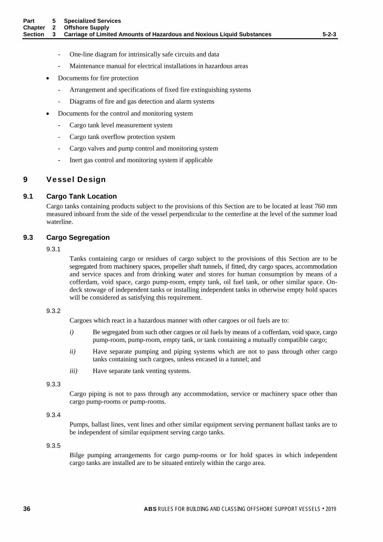
Part 5 Specialized Services Chapter 2 Offshore Supply Section 3 Carriage of Limited Amounts of Hazardous and Noxious Liquid Substances 5-2-3
- One-line diagram for intrinsically safe circuits and data
- Maintenance manual for electrical installations in hazardous areas
• Documents for fire protection
- Arrangement and specifications of fixed fire extinguishing systems
- Diagrams of fire and gas detection and alarm systems
• Documents for the control and monitoring system
- Cargo tank level measurement system
- Cargo tank overflow protection system
- Cargo valves and pump control and monitoring system
- Inert gas control and monitoring system if applicable
9 Vessel Design
9.1 Cargo Tank Location Cargo tanks containing products subject to the provisions of this Section are to be located at least 760 mm measured inboard from the side of the vessel perpendicular to the centerline at the level of the summer load waterline.
9.3 Cargo Segregation 9.3.1
Tanks containing cargo or residues of cargo subject to the provisions of this Section are to be segregated from machinery spaces, propeller shaft tunnels, if fitted, dry cargo spaces, accommodation and service spaces and from drinking water and stores for human consumption by means of a cofferdam, void space, cargo pump-room, empty tank, oil fuel tank, or other similar space. On-deck stowage of independent tanks or installing independent tanks in otherwise empty hold spaces will be considered as satisfying this requirement.
9.3.2 Cargoes which react in a hazardous manner with other cargoes or oil fuels are to:
i) Be segregated from such other cargoes or oil fuels by means of a cofferdam, void space, cargo pump-room, pump-room, empty tank, or tank containing a mutually compatible cargo;
ii) Have separate pumping and piping systems which are not to pass through other cargo tanks containing such cargoes, unless encased in a tunnel; and
iii) Have separate tank venting systems.
9.3.3 Cargo piping is not to pass through any accommodation, service or machinery space other than cargo pump-rooms or pump-rooms.
9.3.4 Pumps, ballast lines, vent lines and other similar equipment serving permanent ballast tanks are to be independent of similar equipment serving cargo tanks.
9.3.5 Bilge pumping arrangements for cargo pump-rooms or for hold spaces in which independent cargo tanks are installed are to be situated entirely within the cargo area.
36 ABS RULES FOR BUILDING AND CLASSING OFFSHORE SUPPORT VESSELS . 2019
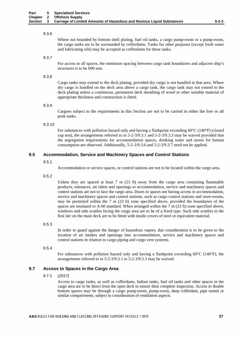
Part 5 Specialized Services Chapter 2 Offshore Supply Section 3 Carriage of Limited Amounts of Hazardous and Noxious Liquid Substances 5-2-3
9.3.6 Where not bounded by bottom shell plating, fuel oil tanks, a cargo pump-room or a pump-room, the cargo tanks are to be surrounded by cofferdams. Tanks for other purposes (except fresh water and lubricating oils) may be accepted as cofferdams for these tanks.
9.3.7 For access to all spaces, the minimum spacing between cargo tank boundaries and adjacent ship’s structures is to be 600 mm.
9.3.8 Cargo tanks may extend to the deck plating, provided dry cargo is not handled in that area. Where dry cargo is handled on the deck area above a cargo tank, the cargo tank may not extend to the deck plating unless a continuous, permanent deck sheathing of wood or other suitable material of appropriate thickness and construction is fitted.
9.3.9 Cargoes subject to the requirements in this Section are not to be carried in either the fore or aft peak tanks.
9.3.10 For substances with pollution hazard only and having a flashpoint exceeding 60°C (140°F) (closed cup test), the arrangements referred to in 5-2-3/9.3.1 and 5-2-3/9.3.3 may be waived provided that the segregation requirements for accommodation spaces, drinking water and stores for human consumption are observed. Additionally, 5-2-3/9.3.6 and 5-2-3/9.3.7 need not be applied.
9.5 Accommodation, Service and Machinery Spaces and Control Stations 9.5.1
Accommodation or service spaces, or control stations are not to be located within the cargo area.
9.5.2 Unless they are spaced at least 7 m (23 ft) away from the cargo area containing flammable products, entrances, air inlets and openings to accommodation, service and machinery spaces and control stations are not to face the cargo area. Doors to spaces not having access to accommodation, service and machinery spaces and control stations, such as cargo control stations and store-rooms, may be permitted within the 7 m (23 ft) zone specified above, provided the boundaries of the spaces are insulated to A-60 standard. When arranged within the 7 m (23 ft) zone specified above, windows and side scuttles facing the cargo area are to be of a fixed type. Such side scuttles in the first tier on the main deck are to be fitted with inside covers of steel or equivalent material.
9.5.3 In order to guard against the danger of hazardous vapors, due consideration is to be given to the location of air intakes and openings into accommodation, service and machinery spaces and control stations in relation to cargo piping and cargo vent systems.
9.5.4 For substances with pollution hazard only and having a flashpoint exceeding 60°C (140°F), the arrangements referred to in 5-2-3/9.5.1 to 5-2-3/9.5.3 may be waived.
9.7 Access to Spaces in the Cargo Area 9.7.1 (2017)
Access to cargo tanks, as well as cofferdams, ballast tanks, fuel oil tanks and other spaces in the cargo area are to be direct from the open deck to ensure their complete inspection. Access to double bottom spaces may be through a cargo pump-room, pump-room, deep cofferdam, pipe tunnel or similar compartments, subject to consideration of ventilation aspects.
ABS RULES FOR BUILDING AND CLASSING OFFSHORE SUPPORT VESSELS . 2019 37

Part 5 Specialized Services Chapter 2 Offshore Supply Section 3 Carriage of Limited Amounts of Hazardous and Noxious Liquid Substances 5-2-3
9.7.1(a) To take care of restrictions in the movement of personnel and to limit the time needed for a possible emergency escape, two separate means of access are to be provided in double bottom tanks and similar spaces where obstructions impede movement. The two accesses are to be as widely separated as practicable.
9.7.1(b) The provision of only one access may be approved in special circumstances if the ability to readily traverse the space or to remove an injured person can be demonstrated.
9.7.2 For access through horizontal openings, hatches or manholes, the dimensions are to be sufficient to allow a person wearing a self-contained air breathing apparatus and protective equipment to ascend or descend any ladder without obstruction and also to provide a clear opening to facilitate the hoisting of an injured person from the bottom of the space. The minimum clear opening is to be not less than 600 mm by 600 mm.
9.7.3 For access through vertical openings, or manholes providing passage through the length and breadth of the space, the minimum clear opening is to be not less than 600 mm by 800 mm at a height of not more than 600 mm from the bottom shell plating unless gratings or other footholds are provided.
Note: For the sizes of access openings defined in 5-2-3/9.7.2 and 5-2-3/9.7.3, the following applies:
i) The term minimum clear opening of not less than 600 × 600 mm means that such opening may have corner radii up to 100 mm maximum.
ii) The term minimum clear opening of not less than 600 × 800 mm includes also openings of the following sizes:
FIGURE 1 Access Openings
600
300
300
800
R200 mm (7.9")
R310 mm (12.2")
A = 850 mm
B = 620 mm
C < 600 mmA
B
C
9.7.4 Smaller dimensions may be approved in special circumstances, if the ability to traverse such openings or to remove an injured person can be demonstrated.
9.9 Cargo Tank Construction 9.9.1
Cargo tanks are to be at least of the type required for the cargo by Section 5C-9-4 or Section 5C-8-4 of the Steel Vessel Rules, as applicable.
38 ABS RULES FOR BUILDING AND CLASSING OFFSHORE SUPPORT VESSELS . 2019

Part 5 Specialized Services Chapter 2 Offshore Supply Section 3 Carriage of Limited Amounts of Hazardous and Noxious Liquid Substances 5-2-3
9.9.2 Portable tanks meeting the requirements of the International Maritime Dangerous Goods (IMDG) Code or other portable tanks specifically approved may be used for cargoes indicated in 5-2-3/1.3.1, provided that the tanks are properly located and secured to the vessel.
9.9.3 Except for the tank connections to cargo pump-rooms, all tank openings and connections to the tank are to terminate above the weather deck and are to be located in the tops of the tanks. Where cofferdams are provided over integral tanks, small trunks are permitted to penetrate the cofferdam.
9.9.4 The greater of the following design pressures (gauge) are to be used for determining scantlings of independent pressure tanks:
i) 0.07 MPa (0.714 kgf/cm2, 10.15 lbs/in2)
ii) The vapor pressure of the cargo at 45°C (113°F)
iii) The vapor pressure of the cargo at 15°C (59°F) above the temperature at which it is normally carried
iv) The pressure which occurs in the tank during the loading or unloading
The design of the tanks is to comply with standards taking into account the carriage temperature and relative density of cargo. Due consideration is to also be given to dynamic forces and any vacuum pressure to which the tanks may be subjected.
9.9.5 Integral and independent gravity tanks are to be constructed and tested according to acceptable recognized standards taking into account the carriage temperature and relative density of cargo.
9.9.6 For substances with pollution hazard only and having a flashpoint exceeding 60°C (140°F), the requirements of 5-2-3/9.9.3 need not be applied.
9.11 Materials of Construction Materials of construction for tanks, piping, fittings and pumps are to be in accordance with Section 5C-9-6 or Section 5C-8-6 of the Steel Vessel Rules, as applicable.
9.13 Cargo Tank Vent Systems 9.13.1
Independent pressure tanks are to be fitted with pressure relief devices that are so designed as to direct the discharge away from personnel and that have a set pressure and capacity which is in accordance with acceptable standards taking into account the design pressure referred to in 5-2-3/9.9.4.
9.13.2 Cargo tank vent systems of integral or independent gravity tanks are to meet the requirements in Part 5C, Chapter 9 of the Steel Vessel Rules, except that the height specified in 5C-9-8/3.4 may be reduced to 2 m.
9.13.3 The location of cargo tank vent outlets for independent pressure tanks or for cargo tanks used for carrying substances with pollution hazard only and flashpoint exceeding 60°C (140°F) (closed cup test) may be specially considered.
9.13.4 Cargo tank vent systems of portable tanks allowed under 5-2-3/9.9.2 may be specially considered, taking into account the requirements of 5-2-3/9.13.
ABS RULES FOR BUILDING AND CLASSING OFFSHORE SUPPORT VESSELS . 2019 39
Part 5 Specialized Services Chapter 2 Offshore Supply Section 3 Carriage of Limited Amounts of Hazardous and Noxious Liquid Substances 5-2-3
9.15 Cargo Transfer 9.15.1
The cargo transfer system is to comply with the requirements of Section 5C-9-5 or 5C-8-5 of the Steel Vessel Rules, taking into account existing industry standards and practices.
9.15.2 (1 July 2012) The remote shutdown devices for all cargo pumps and similar equipment, required by 5C-9-5/6.1.3 of the Steel Vessel Rules, are to be capable of being activated from a dedicated cargo control location which is manned at the time of cargo transfer and from at least one other location outside the cargo area and at a safe distance from it. The requirements for cargo transfer hose emergency disconnection in 5-2-2/5.7.2 are also applicable.
9.17 Electrical Installations Electrical installations are to meet the requirements of Section 5C-9-10 of the Steel Vessel Rules.
9.19 Fire-Fighting Requirements 9.19.1
For the carriage of flammable liquids identified in 5-2-3/Table 1, the requirements for tankers in Chapter II-2 of the 1974 SOLAS Convention, as amended, are to apply to vessels covered by this Section, including vessels of less than 500 gross tonnage, except that:
i) Regulations 4.5.5, 10.8 and 10.9 are not to be applied.
ii) Regulation 4.5.1.1 (i.e., positioning of machinery spaces aft of cargo tanks, slop tanks, cargo pump-rooms and cofferdams), Regulation 4.5.1.2 (i.e. the requirements for location of the main cargo control station), Regulations 4.5.1.4 and 4.5.2.1 to 4.5.2.3 need not be applied. Additionally, Regulation 9.2.4.2.5 need not be applied provided that the exterior boundaries of superstructures and deckhouses enclosing accommodation and including any overhanging decks which support such accommodation are spaced at least 7 m (23 ft) away from the cargo area. The insulation of such boundaries is to be to the satisfaction of ABS.
iii) With regard to Regulation 9.2.4.1, use of a method other than IC as defined in Regulation 9.2.3.1.1.1 may be permitted where considered appropriate.
iv) The requirements of Regulation 9.2.3 may be applied in lieu of those in Regulation 9.2.4.2, where considered appropriate.
v) The provisions of Regulations 4.5.3, 4.5.4 and 4.5.6 to 4.5.8 need be applied only where considered appropriate, taking into account the requirement in 5-2-3/9.13.2 that cargo tank vent systems are to meet the relevant requirements of the International Bulk Chemical Code.
vi) Regulations 10.2, 10.4 and 10.5, except Regulation 10.5.6, are to apply as they would apply to tankers of 2,000 gross tonnage and over.
vii) The provisions of 5-2-3/9.19.2iii) are to be applied in lieu of Regulation 10.8.
viii) The provisions of 5-2-3/9.19.2v) are to be applied in lieu of Regulation 10.9.
9.19.2 The following provisions also apply for the carriage of flammable liquids identified in 5-2-3/Table 1:
i) During cargo transfer, water pressure is to be maintained on the fire main system.
ii) Fire hoses, fitted with approved dual-purpose nozzles (i.e. spray/jet type with a shutoff), are to be attached to each fire hydrant in the vicinity of the flammable liquid to be carried.
40 ABS RULES FOR BUILDING AND CLASSING OFFSHORE SUPPORT VESSELS . 2019

Part 5 Specialized Services Chapter 2 Offshore Supply Section 3 Carriage of Limited Amounts of Hazardous and Noxious Liquid Substances 5-2-3
iii) Either a fixed deck foam system or a fixed fire-extinguishing system of the dry chemical type complying with the following:
• The system is to be located to protect the deck within the cargo area;
• The system is to be capable of covering the deck within the cargo area without being moved;
• When a fixed deck foam system is provided, it is to comply with the requirements of 5C-9-11/3.3 to 5C-9-11/3.12 of the Steel Vessel Rules. Only foam suitable for the products carried is to be used.
• A fixed fire-extinguishing system may be approved provided that:
- On a deck area of 45 m2 (484 ft2) or less, there are two or more dry chemical extinguishers whose total capacity is not less than 135 kg (298 lbs);
- On a deck area of more than 45 m2 (484 ft2), there are three or more dry chemical extinguishers whose total capacity of extinguishing agent is not less than: C = 3A kg where A is the deck area (in m2);
- The minimum rate of supply of the extinguishing agent is not less than 3 kg/min.
iv) An alternative to the systems required in 5-2-3/9.19.2iii) above may be approved in accordance with the procedures contained in SOLAS Regulation II-2/17.
v) The cargo pump-room where flammable liquids are handled is to be provided with a fixed fire-extinguishing system in accordance with 5C-9-11/2 the Steel Vessel Rules.
9.19.3 For vessels which carry only liquids identified as non-flammable in 5-2-3/Table 1, the fire-fighting requirements will be specially considered.
9.21 Acid Spill Protection 9.21.1
Floors or decks under acid storage tanks and pumps and piping for acid are to have a lining or coating of corrosion-resistant material extending up to a minimum height of 500 mm on the bounding bulkheads or coamings. Hatches or other openings in such floors or decks are to be raised to a minimum height of 500 mm; however, where this height is not practicable, a lesser height may be required.
9.21.2 Flanges or other detachable pipe connections are to be covered by spray shields.
9.21.3 Portable shield covers for connecting the flanges of the loading manifold are to be provided. Drip trays of corrosion-resistant material are to be provided under loading manifolds for acids.
9.21.4 Spaces for acid storage tanks and acid pumping and piping are to be provided with drainage arrangements of corrosion-resistant materials.
9.21.5 Deck spills are to be kept away from accommodation and service areas by means of a permanent coaming of suitable height and extension.
9.23 Ventilation of Spaces in the Cargo Area The requirements of Section 5C-9-12 of the Steel Vessel Rules are to be applied. Relaxations concerning the distances required in 5C-9-12/1.5 of the Steel Vessel Rules may be granted.
ABS RULES FOR BUILDING AND CLASSING OFFSHORE SUPPORT VESSELS . 2019 41
Part 5 Specialized Services Chapter 2 Offshore Supply Section 3 Carriage of Limited Amounts of Hazardous and Noxious Liquid Substances 5-2-3
9.25 Vapor Detection 9.25.1
Vapor detection for the cargoes carried is to be provided in accordance with the requirements contained in Section 5C-9-13 of the Steel Vessel Rules.
9.25.2 Enclosed and semi-enclosed spaces containing installations for acid are to be fitted with fixed vapor detection and alarm systems which provide visual and audible indication. The vapor detection systems are to be capable of detecting hydrogen except that in the case where only hydrochloric acid is carried, a hydrogen chloride vapor detection system is to be provided.
9.25.3 At least two portable instruments for detecting flammable vapor concentrations are to be provided when cargoes subject to this Section with a flashpoint not exceeding 60°C (140°F) (closed cup test) are carried.
9.25.4 At least two portable instruments suitable for measuring the concentration of oxygen in atmospheric air are to be provided.
9.27 Special Requirements – General The special requirements for the cargo as referred to Section 5C-9-17 or 5C-8-19 of the Steel Vessel Rules are applicable; however, the requirement in 5C-9-15/19.6 of the Steel Vessel Rules for a visual and audible high-level alarm may be waived taking into account the cargo carriage arrangements and cargo loading procedures.
9.29 Special Requirements for the Carriage of Liquefied Gases 9.29.1
Each enclosed space used for handling or storage of a liquefied gas is to be fitted with a sensor continuously monitoring the oxygen content of the space and an alarm indicating low oxygen concentration. For semi-enclosed spaces portable equipment may also be acceptable.
9.29.2 Drip trays resistant to cryogenic temperatures are to be provided at manifolds transferring liquefied gases or at other flanged connections in the liquefied gas system.
9.29.3 For the carriage of liquid nitrogen the requirements of 5C-8-17/19 of the Steel Vessel Rules are to be applied.
9.29.4 For the construction of cargo tanks and cargo piping systems for liquefied nitrogen and liquid carbon dioxide, the requirements in Part 5C, Chapter 8 of the Steel Vessel Rules are to be applied.
9.29.5 Emergency shutoff valves are to be provided in liquid outlet lines from each liquefied gas tank. The controls for the emergency shutoff valves are to meet the requirements given in 5-2-3/9.15.2 for remote shutdown devices.
9.31 Gauging and Level Detection Each cargo tank is to have an acceptable level gauging system. As a minimum the system is to meet relevant requirements of Part 5C, Chapter 8 or Chapter 9 of the Steel Vessel Rules, as applicable. The systems for process tanks on board well-stimulation vessels are to meet the requirements in 5-11-3/7.3.
42 ABS RULES FOR BUILDING AND CLASSING OFFSHORE SUPPORT VESSELS . 2019
Part 5 Specialized Services Chapter 2 Offshore Supply Section 3 Carriage of Limited Amounts of Hazardous and Noxious Liquid Substances 5-2-3
9.33 Emergency Remote Shutdown In the case of transfer operations involving pressures in excess of 5 MPa (725 lbf/in2), arrangements for emergency depressurizing and disconnection of the transfer hose are to be provided. The controls for activating emergency depressurization and disconnection of the transfer hose are to meet the requirements given in 5-2-3/9.15.2 for remote shutdown devices.
11 Pollution Requirements
11.1 Each ship certified to carry noxious liquid substances is to be provided with a Cargo Record Book, a Procedure and Arrangements Manual and a Shipboard Marine Pollution Emergency Plan developed for the ship in accordance with Annex II to MARPOL 73/78 and approved.
11.3 Discharge into the sea of residues of noxious liquid substances permitted for the carriage in Ship type 3, or products listed in 5-2-3/Table 1 or ballast water, tank washings, or other residues or mixtures containing such substances, is prohibited. Any discharges of residues and mixtures containing noxious liquid substances are to be to reception facilities in port.
13 Personnel Protection
13.1 Decontamination Showers and Eyewashes Except in the case of substances with pollution hazard only, a suitably marked decontamination shower and eyewash are to be available on deck in a convenient location. The shower and eyewash are to be operable in all ambient conditions.
13.3 Protective and Safety Equipment Protective and safety equipment are to be kept on board in suitable locations as required by Section 5C-9-14 or Section 5C-8-14 of the Steel Vessel Rules for products to be carried.
15 Operational Guidance The following operational matters are not required for classification, and are shown for information only.
15.1 Deck cargo and products covered by this Chapter are not to be loaded or unloaded simultaneously.
15.3 Only personnel engaged in the transfer of cargo covered by this Chapter are to be permitted to be in the cargo area and the adjacent open main deck during loading or unloading operations.
ABS RULES FOR BUILDING AND CLASSING OFFSHORE SUPPORT VESSELS . 2019 43

Part 5 Specialized Services Chapter 2 Offshore Supply Section 3 Carriage of Limited Amounts of Hazardous and Noxious Liquid Substances 5-2-3
TABLE 1 Permitted Products
Product Flamm Hazard* 1 Oil based mud containing mixtures of products in Ch. 17 & 18 of IBC Code & MEPC.2/Circular and
permitted to be carried under 5-2-3/1.3 No –
2 Water-based mud containing mixtures of products in Ch. 17 & 18 of IBC Code & MEPC.2/Circular and permitted to be carried under 5-2-3/1.3
No –
3 Drilling brines, including: - Sodium chloride Solution - Calcium bromide Solution - Calcium chloride Solution
No No No
P P P
4 Calcium nitrate/Magnesium nitrate/Potassium chloride solution No P 5 Calcium nitrate solution (50% or less) No P(18) 6 Drilling brines (containing zinc salts) No P 7 Potassium formate solution No P(18) 8 Potassium chloride solution No P/S 9 Ethyl alcohol Yes P(18) 10 Ethylene glycol No P 11 Ethylene glycol monoalkyl ether Yes S/P 12 Methyl alcohol Yes P 13 Acetic acid Yes S/P 14 Formic acid Yes S/P 15 Hydrochloric acid No S/P 16 Hydrochloric-hydrofluoric mixtures containing 3% or less Hydrofluoric acid No S/P 17 Sodium silicate solution No P 18 Sulphuric acid No S/P 19 Triethylene glycol Yes P(18) 20 Toluene Yes P 21 Xylene Yes P 22 Liquid carbon dioxide No S 23 Liquid nitrogen No S 24 Noxious liquid, NF, (7) n.o.s. (trade name ..., contains ...) ST3, Cat. Y No P 25 Noxious liquid, F, (8) n.o.s. (trade name .., contains .) ST3, Cat. Y Yes P 26 Noxious liquid, NF, (9) n.o.s. (trade name ., contains .) ST3, Cat. Z No P 27 Noxious liquid, F, (10) n.o.s. (trade name ., contains .) ST3, Cat. Z Yes P 28 Noxious liquid, (11) n.o.s. (trade name ., contains .) Cat. Z No P(18) 29 Non-noxious liquid, (12) n.o.s. (trade name ., contains .) Cat. OS No P(18)
*Note: Where:
“–” denotes the product could be “P”, “S” or “S/P”
P is pollution hazard substance
S is safety hazard substance
S/P is both safety and pollution hazard substance
44 ABS RULES FOR BUILDING AND CLASSING OFFSHORE SUPPORT VESSELS . 2019
ABS RULES FOR BUILDING AND CLASSING OFFSHORE SUPPORT VESSELS . 2019 45
P A R T C h a p t e r 3 : A n c h o r H a n d l i n g a n d T o w i n g
5 C H A P T E R 3 Anchor Handling and Towing
CONTENTS SECTION 1 General .................................................................................................... 48
1 Application ........................................................................................ 48 3 Classification ..................................................................................... 48 5 Optional Record Entries .................................................................... 48
5.1 Quick Release Device ................................................................... 48 5.3 Drum Overload Clutch ................................................................... 48
7 Submission of Plans and Data .......................................................... 48 7.1 General Arrangement Plan ............................................................ 48 7.3 Structure Plans .............................................................................. 49 7.5 Machinery Plans ............................................................................ 49 7.7 Stability Documents ....................................................................... 49 7.9 Information Documents ................................................................. 49 7.11 Documentation for OSV without AH and TOW notations .............. 50
9 Definitions ......................................................................................... 50 9.1 Static Bollard Pull .......................................................................... 50 9.3 Reference Load ............................................................................. 50 9.5 Operational Pull ............................................................................. 51 9.7 Winch Hoisting Capacity................................................................ 51 9.9 Winch Brake Holding Capacity ...................................................... 51 9.11 Winch Rendering Capacity ............................................................ 51
SECTION 2 Stability ................................................................................................... 52
1 Intact Stability .................................................................................... 52 3 Subdivision and Damage Stability .................................................... 52
SECTION 3 Vessel Design ......................................................................................... 53
1 Side Structures ................................................................................. 53 3 Work Deck......................................................................................... 53
3.1 Reinforcement against Impact, Wear and Tear ............................. 53 3.3 Work Deck Protection .................................................................... 53 3.5 Anchors and Chains Securing Means ........................................... 53 3.7 Cargo Rail ..................................................................................... 53 3.9 Arrangements for Shifting Anchors and Chains ............................. 54
5 Weather Deck Openings ................................................................... 54
46 ABS RULES FOR BUILDING AND CLASSING OFFSHORE SUPPORT VESSELS . 2019
7 Steering Gear .................................................................................... 54 7.1 General .......................................................................................... 54 7.3 Steering Gear ................................................................................ 54 7.5 Rudder ........................................................................................... 54 7.7 Thrusters ........................................................................................ 54 7.9 Special Arrangements.................................................................... 54
SECTION 4 Anchor Handling and Towing Gear ...................................................... 55
1 General ............................................................................................. 55 3 Arrangement ..................................................................................... 55
3.1 Work Deck ..................................................................................... 55 3.3 Gear ............................................................................................... 55
5 Towing and Anchor Handling Lines .................................................. 56 5.1 Towline .......................................................................................... 56 5.3 Anchor Handling Line..................................................................... 56 5.5 Bend Radius .................................................................................. 56
7 Anchor Handling/Towing Winch and Accessories ............................ 56 7.1 Arrangement and Control ............................................................... 56 7.3 Mechanical Design ........................................................................ 56 7.5 Towing Pins and Towing Eyes ....................................................... 58 7.7 Shark Jaws .................................................................................... 58 7.9 Stern Roller .................................................................................... 58 7.11 Bollards and Other Deck Fittings ................................................... 59 7.13 A-frame or Shear Leg Type Crane ................................................. 59 7.15 Materials and Fabrication ............................................................... 59
FIGURE 1 ....................................................................................................... 58 FIGURE 2 ....................................................................................................... 59
SECTION 5 Tests ........................................................................................................ 60
1 Quick Release Device Test ............................................................... 60 3 Drum Overload Clutch Test .............................................................. 60 5 Static Bollard Pull Test ...................................................................... 60
APPENDIX 1 Guidelines for Static Bollard Pull Test Procedure .............................. 61
1 General ............................................................................................. 61 3 Static Bollard Pull Test Requirements .............................................. 61
APPENDIX 2 Intact Stability Guidelines for Anchor Handling ................................. 63
1 Additional Intact Stability Criteria ...................................................... 63 1.1 Intact Stability ................................................................................ 63 1.3 Loading Conditions ........................................................................ 63 1.5 Stability Guidance for the Master ................................................... 64
ABS RULES FOR BUILDING AND CLASSING OFFSHORE SUPPORT VESSELS . 2019 47
APPENDIX 3 Intact Stability Guidelines for Towing ................................................. 65 1 General ............................................................................................. 65 3 Intact Stability Criteria ....................................................................... 65
3.1 Towing Operating .......................................................................... 65 5 Heeling Arm Curve ............................................................................ 66 7 Stability Guidance for the Master ...................................................... 66 TABLE 1 Towline Pull Force................................................................... 66 FIGURE 1 Righting Arm and Heeling Arm Curves ................................... 65

48 ABS RULES FOR BUILDING AND CLASSING OFFSHORE SUPPORT VESSELS . 2019
P A R T S e c t i o n 1 : G e n e r a l
5 C H A P T E R 3 Anchor Handling and Towing
S E C T I O N 1 General
1 Application The requirements in this Chapter apply to Offshore Support Vessels equipped for the handling of anchors of offshore floating installations or equipped for towing operations.
3 Classification In accordance with Section 1-1-2 of the OSV Rules Supplement to the ABS Rules for Conditions of Classification (Part 1) and 5-1-1/5.1 of these Rules, the classification À A1 Offshore Support Vessel (AH) is to be assigned to Offshore Support Vessels equipped for anchor handling and designed and built to the requirements of this Chapter and other relevant sections of these Rules.
The classification À A1 Offshore Support Vessel (TOW) is to be assigned to Offshore Support Vessel equipped for towing designed and built to the requirements of this Chapter and other relevant sections of these Rules.
Where a vessel is equipped for multi-function operations, the appropriate class notations are to be assigned. For example, an Offshore Support Vessel equipped for anchor handling and towing is to be assigned the classification À A1 Offshore Support Vessel (AH,TOW). Other combinations of class notations described may be assigned commensurate with the functional and service capabilities of the vessel for which it has been approved as described in Section 5-1-1 of these Rules.
5 Optional Record Entries
5.1 Quick Release Device At the request of the owner, where an approved remotely controlled quick release device is provided for the towing rope or towing wire the letters QR will be entered in the Record.
5.3 Drum Overload Clutch At the request of the owner, where an approved, winch drum overload clutch is provided between the drum’s hub and the winch drum, the letters DOC will be entered in the Record.
7 Submission of Plans and Data (2018) In general, in addition to the plans listed in Section 1-1-4 of the OSV Rules Supplement to the ABS Rules for Conditions of Classification (Part 1), the following plans and particulars are to be submitted.
7.1 General Arrangement Plan Anchor handling and towing arrangement plan showing all of the equipment/components of the handling and towing system such as winches, ropes and/or wires, components on anchor handling line path and towline path, quick release devices (if installed) and control stations as well as design criteria including the expected static bollard pull (BP), reference load (RL), hoisting, brake holding and rendering capacities of the winch, quick release speed, as applicable and the most extreme towline directions, etc.
Part 5 Specialized Services Chapter 3 Anchor Handling and Towing Section 1 General 5-3-1
ABS RULES FOR BUILDING AND CLASSING OFFSHORE SUPPORT VESSELS . 2019 49
7.3 Structure Plans i) Structural details of supporting structures in way of the anchor handling and towing winches
ii) Structural details of stern roller, towing pins, shark jaw and their supporting structure
iii) Details of stow racks, cargo rails, crash rails and supporting structures
iv) Spare chain locker(s) structural details including chutes (if installed)
v) Structural details of A-frame and deck cranes, if certification is requested
vi) Structural details of supporting structures of A-frames and deck cranes
vii) Detailed drawings showing dimensions, materials, welding details, as applicable, of stern rollers and towing eyes/hooks (if installed), etc.
viii) Design analysis of structures and deck fittings on the load path
ix) Nondestructive testing (NDT) plans
7.5 Machinery Plans i) Anchor handling and towing winch assembly plans including prime mover and brakes
ii) Detailed drawings showing dimensions, materials, welding details, as applicable, of all load bearing components of the winch
iii) Shark jaws and towing pins units assembly plans
iv) Detailed drawings showing dimensions, materials, welding details, as applicable, of shark jaws and towing pins
v) Detailed drawing of quick release devices, where the entry QR in the Record is requested (refer to 5-3-4/7.1.2)
vi) Design analyses for load bearing components. Analyses for gears are to be in accordance with a recognized standard
vii) Nondestructive testing (NDT) plans
viii) Hydraulic piping system diagram along with system design pressure, relief valve setting, bill of materials, typical pipe joints, as applicable
ix) Electric one line diagram along with cable specification and size; motor controller; protective device rating or setting; as applicable
x) Control, monitoring and instrumentation arrangements
xi) Plans and data for winch hydraulic or electric motors including associated gears rated 100 kW (135 hp) and over.
7.7 Stability Documents Stability calculations and corresponding information for the Master are to be submitted for review and approval. See Section 5-3-2 for the detail requirements.
7.9 Information Documents i) Locations, weights and centers of gravity of anchor handling, towing and secondary winches
(storage reels)
ii) Arrangement and details of communication systems between anchor handling operation control stations and Navigation Bridge
iii) Design loads and locations of rollers, towing eyes/hooks A-frame and deck cranes, shark jaws and towing pins and other components on anchor handling line path and towline path as well as quick release devices (if installed)
iv) Anchor launch and recovery unit for deep penetrating anchors (if installed)

Part 5 Specialized Services Chapter 3 Anchor Handling and Towing Section 1 General 5-3-1
50 ABS RULES FOR BUILDING AND CLASSING OFFSHORE SUPPORT VESSELS . 2019
v) Pad-eyes for securing and lashing anchors on deck
vi) Type, lengths, diameters and minimum specified breaking strength of ropes and/or wires to be set on the above winches
vii) Laying arrangement and weights of anchors carried as cargo
viii) Estimated static bollard pull, together with the method of prediction. (The estimated value is to be confirmed at Trials prior to final certification)
ix) Estimated operational pull within speed range of 0-8 knots at 1 knot intervals, together with the method of prediction (The estimated values may be based on tank test results of required power and allowable trust curves. CFD techniques may be utilized for this purpose as well. The required power values are to be multiplied by the factor of 1.4 to accommodate potential power increase, necessary for station keeping in extreme environmental conditions)
x) Static Bollard Pull Test Procedure (to be review by the attending Surveyor in advance of the test)
7.11 Documentation for OSV without AH and TOW notations If the OSV is equipped for the handling of anchors or towing operations but not assigned with AH and TOW notations, anchor handling and towing systems may be accepted based on, but not limited to the documentation listed below, as applicable and functional test satisfied to the attending Surveyor.
i) Manufacturer’s affidavit of compliance to the applicable codes and/or standards with the design capacities or design loads for winches or components on anchor handling line path and towline path
ii) General arrangement plan (refer to 5-3-1/7.1)
iii) Structure plans, excluding deck fittings (refer to 5-3-1/7.2)
iv) Stability documents (refer to 5-3-1/7.4 and Section 5-3-2)
v) Information documents (refer to 5-3-1/7.5)
vi) OSV related hydraulic and electrical systems drawings showing the proposed modifications where hydraulic system and electrical power supply/control systems are going to be tied into the related vessels systems.
9 Definitions
9.1 Static Bollard Pull (2016) Static bollard pull (BP) for use in 5-3-1/9.3 is the maximum sustained towline force the vessel is capable of generating at maximum power (100% MCR) and zero forward speed.
This force (BP) is to be initially specified by the Designer and is to be verified by a bollard pull test, see 5-3-1/7, which will be entered in the Record.
9.3 Reference Load (2016) Reference Load (RL) is to be calculated as below:
For T ≤ 40 tf (39 Ltf); RL = 2.5T
For 40 tf < T < 100 tf RL = [(346.6 – T)/122] tf (Ltf)
For T ≥ 100 tf (98 Ltf); RL = 2.0T
where
T = BP for towing line and towing winch
= design load of anchor handling: maximum forces from the hoisting, rendering and braking including dynamic effects, whichever is greater, stipulated by the owner. Maximum force specified is not to be more than BP verified by a bollard pull test.
Part 5 Specialized Services Chapter 3 Anchor Handling and Towing Section 1 General 5-3-1
ABS RULES FOR BUILDING AND CLASSING OFFSHORE SUPPORT VESSELS . 2019 51
9.5 Operational Pull Operational pull (OP) is the pull at a given speed that is actually available for the anchor handling operation, with propulsive power deductions due to station keeping as well as environmental and resistance forces accounted for. Operational pull is always lower than bollard pull.
9.7 Winch Hoisting Capacity (2016) The rated winch hoisting capacity is the maximum line pull (tension force) including dynamic effects that a winch is able to haul before stalling.
9.9 Winch Brake Holding Capacity (2016) The winch brake holding capacity is the maximum line pull (tension force) a winch can withstand without slipping of the brake.
9.11 Winch Rendering Capacity (2016) The winch rendering capacity is the maximum line pull (tension force) at the drum exit when the drum just starts rotating in the opposite direction of the applied driving torque with a first layer of rope wound on the drum.

52 ABS RULES FOR BUILDING AND CLASSING OFFSHORE SUPPORT VESSELS . 2019
P A R T S e c t i o n 2 : S t a b i l i t y
5 C H A P T E R 3 Anchor Handling and Towing
S E C T I O N 2 Stability
1 Intact Stability The intact stability of anchor handling and/or towing vessels is to comply with Section 3-3-1. In addition, the requirements in Appendices 5-3-A2 and/or 5-3-A3 are to be met. Stability calculations and corresponding information for the Master are to be submitted for review and approval. The submission of evidence showing approval by an Administration of stability of the vessel for the towing operations in accordance with a recognized standard may be acceptable.
3 Subdivision and Damage Stability The subdivision and damage stability of anchor handling and/or towing vessels are to comply with Section 3-3-1.

ABS RULES FOR BUILDING AND CLASSING OFFSHORE SUPPORT VESSELS . 2019 53
P A R T S e c t i o n 3 : V e s s e l D e s i g n
5 C H A P T E R 3 Anchor Handling and Towing
S E C T I O N 3 Vessel Design
1 Side Structures (2014) For vessels subject to impact loads during anchor handling or towing operations, see 3-2-2/3.11, 3-2-5/11 and 3-2-6/11.
3 Work Deck
3.1 Reinforcement against Impact, Wear and Tear (1 July 2012) Plating thickness at the aft portion of the work deck is to be increased to protect the structure against heavy impact loads and wear and tear. It is recommended that minimum plating thickness in this area be not less than 25 mm (1 in.). Alternative arrangements will be considered on case by case basis for re-enforcement against impact and wear and tear. Where heavy anchors and/or chains are carried on deck, suitable means for distributing their weights properly to deck structures are to be provided. The stresses in deck members are not to exceed the following values.
σ N/mm2 (tf/cm2, ltf/in2)
τ N/mm2 (tf/cm2, ltf/in2)
Longitudinal Beam/Girder: Transverse Beam/Web:
124 (1.26, 8.0) 140 (1.42, 9.0)
69 (0.70, 4.4) 85 (0.87, 5.5)
3.3 Work Deck Protection The aft deck areas exposed to anchor drags should not be fitted with sheathings or if present, the sheathings are to be suitably protected. In addition, any protrusion above deck such as coamings, manholes, lashing pad eyes, etc. shall be avoided.
The deck plating thickness in these areas shall be suitably increased to allow for abrasion and mechanical damage.
3.5 Anchors and Chains Securing Means Pad eyes for securing and/or moving the anchors and/or chains are to be welded directly to the deck plating without doublers. The deck in way of the pad-eyes is to be adequately reinforced. Removable pad eyes are to have firm attachment to the deck sockets or holdings. All pad eyes are to be permanently marked with bead welded SWL values.
3.7 Cargo Rail Cargo rails are to be as per 5-2-2/1.9. The cargo rail may be constructed from stanchions topped with the rails, which are to be provided with towline stoppers limiting the line’s sweep. The towline lay over the rail should be such as to provide safe and unobstructed passage behind the cargo rails.
Cargo rails installed athwartship just abaft of the anchor handling/towing winch, are to protect the winch against damage from work deck operations, as well as to separate and support the wires/chains coming off the winch.

Part 5 Specialized Services Chapter 3 Anchor Handling and Towing Section 3 Vessel Design 5-3-3
54 ABS RULES FOR BUILDING AND CLASSING OFFSHORE SUPPORT VESSELS . 2019
3.9 Arrangements for Shifting Anchors and Chains The foundations of tugger winches and/or capstans are to be welded directly to the deck plate and with adequate reinforcement underneath.
5 Weather Deck Openings Openings in the weather deck leading to spaces below the freeboard or superstructure deck, including emergency exits, are to be protected as required in 3-2-15/21.3 with sill height of doors at least as required by 3-2-15/21.7 for companionways. Access openings, including emergency exits, are to be located clear off the towline sweep area.
7 Steering Gear
7.1 General Anchor handling and towing vessels are to have suitable steering gear and arrangements to ensure course keeping capability under all normal anchor handling and towing operation conditions.
7.3 Steering Gear (2014) In addition to the requirements in 4-3-4/1.9.1, the steering gear is to be capable of turning the rudder from 35° on one side to 30° on the other side within 20 seconds, when the vessel is running ahead at maximum service speed. An alternative test procedure may be considered for demonstrating this capability.
7.5 Rudder Rudder size and rudder force are to be suitable for the expected anchor handling / towing conditions and speed. The speed of the vessel used for the rudder design is not to be taken less than 10 knots.
7.7 Thrusters (2015) Where azimuthal thrusters or azimuthing pods are fitted as necessary means for maneuvering of the vessel, the provisions in Section 4-3-5 are applicable and the steering system performance is to meet the requirements in 5-3-3/7.3.
7.9 Special Arrangements Steering units, thruster types and combination arrangements not explicitly covered by this Subsection will be considered based on the manufacturer’s submittal on design and engineering analysis.

ABS RULES FOR BUILDING AND CLASSING OFFSHORE SUPPORT VESSELS . 2019 55
P A R T S e c t i o n 4 : A n c h o r H a n d l i n g a n d T o w i n g G e a r
5 C H A P T E R 3 Anchor Handling and Towing
S E C T I O N 4 Anchor Handling and Towing Gear
1 General (2018) In addition to compliance with applicable ABS Rule and statutory requirements, equipment and systems for anchor handling and towing services with AH and/or TOW notation are to comply with the requirements in this Section. Alternatively, equipment complying with a recognized standard may be accepted provided the recognized standard is not less effective and the same can be verified per the design documentation submitted (refer to 5-3-1/7, as applicable). Equipment and systems for anchor handling and towing services are to be approved and inspected by ABS.
Vessels with notation AH are to be fitted with the following items:
• Anchor handling winch(es)
• Stern roller for anchor handling operations
• Towing pins in way of the stern roller for limiting transverse movement of the line or chain
• Equipment for temporarily securing an anchor (e.g., shark jaw, etc.)
Vessels with notation TOW are to be fitted with the following items:
• Towing winch or towing eyes/hook
• Heavy duty bollards (if installed for towing specially)
3 Arrangement
3.1 Work Deck Safe havens and escape routes for personnel from the work deck are to be properly marked and kept clear at all times. A crash barrier (cargo rail) fitted along each side of the deck and/or aft may be the method of providing a safe haven.
3.3 Gear Anchor handling and towing winches, storage reels, towing hook, towing bitt and towing bollard are to be located as low as practicable, and preferably be arranged in the way of the vessel’s centerline in such a position that the working point of the line force is to be close to, but abaft of, the center of gravity of the vessel in the expected operational conditions.
Towing pins, towing eyes (if provided) and wire stoppers are to be arranged so as to contain the towline within the design limits of its sweep and slack. Means are to be provided to lead and spool the towline on the winch drum in a controlled manner under all foreseeable conditions and direction of the towline.

Part 5 Specialized Services Chapter 3 Anchor Handling and Towing Section 4 Anchor Handling and Towing Gear 5-3-4
56 ABS RULES FOR BUILDING AND CLASSING OFFSHORE SUPPORT VESSELS . 2019
5 Towing and Anchor Handling Lines
5.1 Towline The towline may be either steel wire or fiber rope of the appropriate diameter. The breaking strength of towline is to be not less than the Reference Load (RL). See 5-3-1/9.3.
5.3 Anchor Handling Line The anchor handling line may be either steel wire or fiber rope of the appropriate diameter. The breaking strength of anchor handling line is to be not less than the Reference Load (RL). See 5-3-1/9.3.
5.5 Bend Radius Cargo rails, bulwarks, stern rail, tailgate and other structural elements on which the towline or anchor handling line may bear during normal operations are to have a suitable bend radius.
7 Anchor Handling/Towing Winch and Accessories
7.1 Arrangement and Control 7.1.1 Control Stations (2018)
Anchor handling and towing winches are to be capable of being operated from control stations located on the bridge and at least one additional position on deck with a clear view to the drums.
Each control station is to be equipped with suitable control elements, such as operating levers, with their functions clearly marked. Wherever practical, control levers are to be moved in the direction of the intended towline movement. The operating lever, when released, is to return into the stop position automatically and is to be capable of being secured in the stop position.
Means are to be provided for measuring the tension of the anchor handling/towing line, for display at the control desk on the navigation bridge or another appropriate location for initial and periodic calibration of line tension measuring instrumentation.
7.1.2 Quick Release Device Where the entry QR in the Record is requested in accordance with 5-3-1/5.1, the quick release device for either the anchor handling or towing rope or wire is to be operable from the control station on the bridge or other normally manned location in direct communication with the bridge. The quick release device is to be capable of disengaging the line at any combination of expected trim and heel. It is to be operable in a black-out of the electrical power system and protected against unintentional operation. Procedures describing emergency release methods, time delays and release speed are to be specified and posted at the control stands. See the test requirements for quick release devices in 5-3-5/1.
7.1.3 Power Supply Where the power supply for normal operation of the anchor handling or towing winch is taken from the same source for propulsion, such as shaft generator, shaft power take-off (PTO), an independent (redundant) power supply with sufficient capacity for the winch operation is to be available to ensure the vessel’s maneuvering capability during anchor handling or towing operations is not degraded.
7.3 Mechanical Design 7.3.1 Anchor Handling Winch
7.3.1(a) Winch Holding and Braking Capabilities (2016).
• Winch Holding Capacity: The holding capacity of the anchor handling winch (anchor handling line in the first layer) shall correspond to 80% of the minimum breaking load of the anchor handling line (see 5-3-4/5.3), but need not exceed reference load RL as defined in 5-3-1/9.3.

Part 5 Specialized Services Chapter 3 Anchor Handling and Towing Section 4 Anchor Handling and Towing Gear 5-3-4
ABS RULES FOR BUILDING AND CLASSING OFFSHORE SUPPORT VESSELS . 2019 57
The maximum stress in each load bearing components will not exceed minimum specified yield strength (or 0.2% proof stress) of the material.
• Braking Capacity: The capacity of brake on drum is to be capable of holding at least 1.25 times the maximum torque created from the anchor handling line at design load T as defined in 5-3-1/9.3. The stress level of load bearing components is to be limited to 0.67 times minimum specified yield strength. In addition, the brake is to be capable of stopping the rotation of the drum from its maximum rotating speed.
Evaluation by means of Finite Element Analysis, direct calculation, or equivalent, is to be provided for verifying the maximum stress and deformation of load bearing components of winch under the required holding capacity or braking capacity respectively. Buckling and fatigue to be considered according to recognized standard or code of practice.
7.3.1(b) Winch Brakes. Each winch is to be provided with a power control braking means such as regenerative, dynamic, counter torque breaking, controlled lowering or a mechanically controlled braking means capable of maintaining controlled lowering speeds.
Brakes are to be applied automatically upon loss of power or when the winch lever is returned to neutral.
7.3.2 Towing Winch The towing winch is to be capable of sustaining RL without permanent deformation.
7.3.3 Anchor Handling/Towing Winch A winch intended for both functions of anchor handling and towing is to meet the requirements of 5-3-4/7.3.1 and 5-3-4/7.3.2.
7.3.4 Towline Attachment Anchor handling and towing winches are to be designed in such a way as to allow release of drums and the fast release of lines in an emergency and in all operating conditions. The speed of paying out the lines is to be such as to relieve the tension forces acting on the winch as quickly as possible. The end attachment of the lines to the winch drums is to be of limited strength to allow the lines to part from the winch drums.
Where entry DOC in the Record is requested in accordance with 5-3-1/5.3, the drum overload clutches for the winch drums are to be capable of being remotely pre-set from the control station on the bridge. See test requirements for drum overload clutches in 5-3-5/3.
7.3.5 Winch Supporting Structures (2018) Supporting structural elements of the towing winch are to be capable of sustaining the Reference Load defined in 5-3-1/9.3 without any permanent deformation.
Supporting structural elements of the anchor handling winch are to be capable of sustaining the maximum brake holding capacity without any permanent deformation
In addition, the buckling strength of supporting structural elements is to be sufficient.
Doubler plates are not allowed between the winch foundation and the deck plating, a thicker insert plate is to be applied, if necessary.
Stresses in the structural elements supporting the winch are not to exceed:
Normal stress = 0.75Y
Shear stress = 0.45Y
Where Y is the specified minimum tensile yield strength or yield point. When the evaluation of the winch supporting structure is carried out by direct analysis using finite element methods, refer to 3-2-20/Table 2 for stress limits.
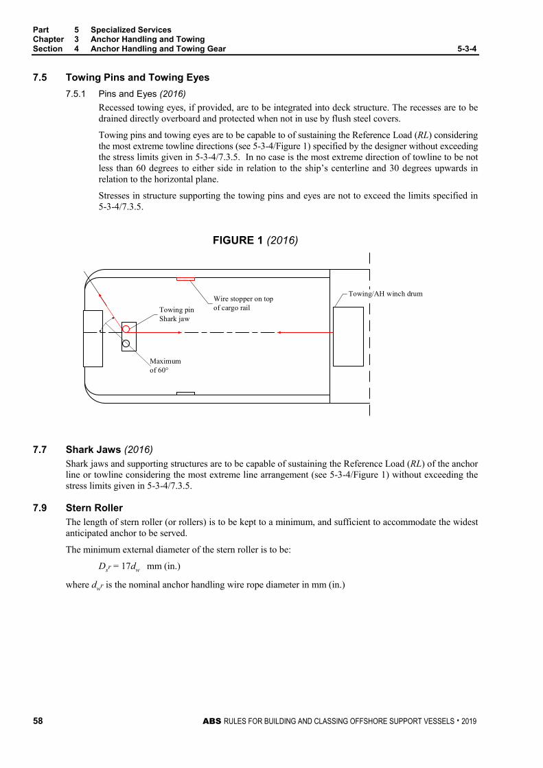
Part 5 Specialized Services Chapter 3 Anchor Handling and Towing Section 4 Anchor Handling and Towing Gear 5-3-4
58 ABS RULES FOR BUILDING AND CLASSING OFFSHORE SUPPORT VESSELS . 2019
7.5 Towing Pins and Towing Eyes 7.5.1 Pins and Eyes (2016)
Recessed towing eyes, if provided, are to be integrated into deck structure. The recesses are to be drained directly overboard and protected when not in use by flush steel covers.
Towing pins and towing eyes are to be capable to of sustaining the Reference Load (RL) considering the most extreme towline directions (see 5-3-4/Figure 1) specified by the designer without exceeding the stress limits given in 5-3-4/7.3.5. In no case is the most extreme direction of towline to be not less than 60 degrees to either side in relation to the ship’s centerline and 30 degrees upwards in relation to the horizontal plane.
Stresses in structure supporting the towing pins and eyes are not to exceed the limits specified in 5-3-4/7.3.5.
FIGURE 1 (2016)
Wire stopper on top of cargo railTowing pin
Shark jaw
Towing/AH winch drum
Maximum of 60°
7.7 Shark Jaws (2016) Shark jaws and supporting structures are to be capable of sustaining the Reference Load (RL) of the anchor line or towline considering the most extreme line arrangement (see 5-3-4/Figure 1) without exceeding the stress limits given in 5-3-4/7.3.5.
7.9 Stern Roller The length of stern roller (or rollers) is to be kept to a minimum, and sufficient to accommodate the widest anticipated anchor to be served.
The minimum external diameter of the stern roller is to be:
Dsr = 17dw mm (in.)
where dwr is the nominal anchor handling wire rope diameter in mm (in.)

Part 5 Specialized Services Chapter 3 Anchor Handling and Towing Section 4 Anchor Handling and Towing Gear 5-3-4
ABS RULES FOR BUILDING AND CLASSING OFFSHORE SUPPORT VESSELS . 2019 59
FIGURE 2
Winch
Roller
30°
The roller, pin connections, foundations and supporting structure are to be designed to the breaking strength of the anchor line. The load is to be applied as shown in 5-3-4/Figure 2. The stresses are not to exceed the following the limits given in 5-3-4/7.3.5.
7.11 Bollards and Other Deck Fittings (2018) The sizes and design loads of bollards and other deck fittings for anchor handling and/or towing operations are to be in accordance with 3-5-1/15.
7.13 A-frame or Shear Leg Type Crane Where an A-frame or shear leg type crane is installed for anchor handling, it is to be certified for compliance with Chapter 2, “Guide for Certification of Cranes”, of the Lifting Appliances Guide.
7.15 Materials and Fabrication (2018) 7.15.1 Materials
i) Materials entered into the construction of torque-transmitting and load-bearing parts of anchor handling/towing winches are to comply with material specifications in either Chapter 3 of the ABS Rules for Materials and Welding (Part 2) or a recognized material standard.
ii) Shark jaw and towing pins with attachment shall be made of rolled, forged, or cast steel in accordance with Chapter 3 of the ABS Rules for Materials and Welding (Part 2).
iii) Stern roller, bollards, and other deck fittings are to comply with material specifications in Chapter 1 of the ABS Rules for Materials and Welding (Part 2). Where they are made in accordance with recognized standards (e.g., ISO 13795), the material shall meet the related requirements in the applicable recognized standard.
iv) The proposed materials are to be indicated in the construction plans and are to be approved in connection with the design. All such materials are to be certified by the material manufacturers approved by ABS and are to be traceable to the manufacturers’ certificates; otherwise, material tests need to be witnessed by Surveyor.
7.15.2 Welded Fabrication Weld joint designs are to be shown in the construction plans and are to be approved in association with the equipment and components design. Welding procedures and welders are to be qualified in accordance with Chapter 4 of the ABS Rules for Materials and Welding (Part 2). Welding consumables are to be approved and listed in accordance with 2-4-3/3 of the ABS Rules for Materials and Welding (Part 2) or are to be of a type acceptable to the Surveyor.

60 ABS RULES FOR BUILDING AND CLASSING OFFSHORE SUPPORT VESSELS . 2019
P A R T S e c t i o n 5 : T e s t s
5 C H A P T E R 3 Anchor Handling and Towing
S E C T I O N 5 Tests
1 Quick Release Device Test Where the entry QR in the Record is requested in accordance with 5-3-1/5.1, effectiveness of the quick release device is to be demonstrated during trials conducted at manufacturers’ premises in presence of the Surveyor.
3 Drum Overload Clutch Test Where the entry DOC in the Record is requested in accordance with 5-3-1/5.3 the effectiveness of the drum overload clutches is to be demonstrated during winch acceptance trials conducted at manufacturer’s premises in presence of the Surveyor.
5 Static Bollard Pull Test (2014) The static bollard pull test procedure is to be submitted for review by the attending Surveyor in advance of the test.
The first vessel of a series is to have a bollard pull test conducted in all cases. The requirements for conducting a bollard pull test on vessels of duplicate design and built in a series will be specially considered on a case-by-case basis. However, a bollard pull test certificate will only be issued to those vessels for which the BP notation is requested and the bollard pull test is actually carried out.
The static bollard pull is to be measured with the vessel at the maximum continuous rpm and at or near the maximum towing depth.
The static bollard pull is the pull that is recorded over the state of equilibrium without any tendency to decline.
The depth of water under the keel in the testing area should be at least two times the vessel draft at amidships.
For additional test criteria, see Appendix 5-3-A1 “Guidelines for Bollard Pull Test Procedure”.

ABS RULES FOR BUILDING AND CLASSING OFFSHORE SUPPORT VESSELS . 2019 61
P A R T A p p e n d i x 1 : G u i d e l i n e s f o r S t a t i c B o l l a r d P u l l T e s t P r o c e d u r e
5 C H A P T E R 3 Anchor Handling and Towing
A P P E N D I X 1 Guidelines for Static Bollard Pull Test Procedure
1 General This Appendix is prepared as a guide for compliance with the requirements of 5-3-5/5.
Prior to conducting the static bollard pull test, a written request should be received from the Owner of ABS attendance and addressing items 5-3-A1/3.15 and 5-3-A1/3.17 below. Only ABS-classed vessels may be attended for the test.
3 Static Bollard Pull Test Requirements
3.1 The towing vessel should be on an even keel or trimmed to the intended operating condition in tow.
3.3 The draft of the towing vessel should be equal to or deeper than ballast condition, but need not be down to the summer load line mark.
3.5 Depth of water under the keel and free water width on each side of the vessel should be at least twice the vessel’s draft amidships.
3.7 If current exceeds 1 knot, its effect is to be subtracted from the bollard pull by either:
i) Direct measurement of drag effect (pulling direction downstream) and reduction of bollard pull accordingly; or,
ii) Conducting pull test both upstream and downstream and averaging the results.
3.9 The distance from the stern of the towing vessel to the bollard (fixed point) should be at least two ship lengths and be unobstructed by submerged pilings, bulwarks etc.
3.11 Wind speed should be 10 mph or less, or such, that it does not measurably affect the bollard pull results.
3.13 Sea condition should be calm.
3.15 A statement should be obtained from the vessel’s Master or Owner’s Representative, that the installed propellers are those approved by ABS for the vessel.

Part 5 Specialized Services Chapter 3 Anchor Handling and Towing Appendix 1 Guidelines for Static Bollard Pull Test Procedure 5-3-A1
62 ABS RULES FOR BUILDING AND CLASSING OFFSHORE SUPPORT VESSELS . 2019
3.17 The Owners should be satisfied as to the structural adequacy of the towing hawser, towing winch or tow bitts employed during the test.
3.19 The vessel’s stability letter should include the towing condition.
3.21 (2017) The dynamometer (load cell) used for the test should be calibrated and suitable for use in horizontal position. It is to be fitted with swivels or be torque insensitive, such as a hydraulic dynamometer. It should be easily read from a safe location or a remote readout should be provided. A continuous recording device is mandatory when only one Surveyor attends. It is suggested that the maximum scale reading be, as a minimum, at least equal to MCR in hp × 24.5 kg (54 lb). The dynamometer should be located at the ashore end of the tow hawser.
3.23 The vessel’s main engines is not to be adjusted to operate in overload condition. Engine over-speed trip setting should be verified prior to commencing the test and monitored during the test.
3.25 The Static Bollard Pull is to be computed as the average of evenly spaced load cell recordings taken over a sustained pull interval of three to five minutes. If the tow hawser is not horizontal, the vertical angle of the hawser is to be measured and used to obtain the actual horizontal thrust.
Engine temperatures are to be at steady state during the test run. Engines should be operated at the ABS maximum continuous rating (certified horsepower as per the Record) and instantaneous spike bollard pull readings should be ignored.
3.27 (1 July 2019) Two Surveyors are required when conducting the test, one ashore and one in the engine room. A two-way voice communication system is to be provided for the test.
Consideration may be given to conducting the test with one Surveyor in the engine room, providing a continuous recording device is used to record the bollard pull. This relaxation of two Surveyor requirements is to be included in a written request submitted as noted in 5-3-A1/1.

ABS RULES FOR BUILDING AND CLASSING OFFSHORE SUPPORT VESSELS . 2019 63
P A R T A p p e n d i x 2 : I n t a c t S t a b i l i t y G u i d e l i n e s f o r A n c h o r H a n d l i n g
5 C H A P T E R 3 Anchor Handling and Towing
A P P E N D I X 2 Intact Stability Guidelines for Anchor Handling
1 Additional Intact Stability Criteria
1.1 Intact Stability For vessels that are used for anchor handling and which at the same time are utilizing their towing capacity and/or tractive power of the winches, calculations are to be made showing the acceptable vertical and horizontal transverse force/tension to which the vessel can be exposed. The calculations are to consider the most unfavorable conditions for vertical and transverse force/tension and as a minimum include the following:
i) Calculations are to be made for the maximum acceptable tension in wire/chain, including the maximum acceptable transverse force/tension that can be accepted in order for the vessel’s maximum heeling to be limited to one of the following angles, whichever occurs first:
• Heeling angle equivalent to a GZ value equal to 50% of GZ max
• The angle which results in water on working deck when the deck is calculated as flat
• 15 degrees
ii) The heeling moment is to be calculated as the total effect of the horizontal and vertical transverse components of force/tension in the wire or the chain. The torque arm of the horizontal components shall be calculated as the distance from the height of the work deck at the guide pins to the center of main propulsion propeller or to center of stern side propeller if this projects deeper. The torque arm of the vertical components is to be calculated from the center of the outer edge of the stern roller and with a vertical straining point on the upper edge of the stern roller.
1.3 Loading Conditions The following loading conditions intended for anchor handling are to be examined in the Trim and Stability Booklet:
i) Vessel at the maximum Load Line draft, with full stores and fuel and fully loaded with all liquid and dry cargo distributed below deck and with remaining deadweight distributed as above deck weight (anchors, chain, etc., specified by weight, LCG, VCG and total height above deck) corresponding to the worst service departure condition in which all the relevant stability criteria are met.
ii) Vessel with 10% stores and fuel and fully loaded cargoes of i) above, arrival condition.
iii) Vessel at the maximum Load Line draft, with full stores, a full set of rig anchors on deck to be deployed during single trip (and rig chains, if appropriate) and fuel loaded to the maximum deadweight, corresponding to the worst service departure condition in which all the relevant stability criteria are met.
iv) Vessel with 10% stores and fuel and fully loaded cargoes of iii) above, arrival condition.
v) Vessel in worst anticipated operating condition.

Part 5 Specialized Services Chapter 3 Anchor Handling and Towing Appendix 2 Intact Stability Guidelines for Anchor Handling 5-3-A2
64 ABS RULES FOR BUILDING AND CLASSING OFFSHORE SUPPORT VESSELS . 2019
These conditions are to include the following items:
• The loads on the deck (including the weight of anchors, chains and lines) and winch reels (loaded with heaviest possible line types).
• The vertical force from the tension, upon which calculations of trim and curve for righting arm are based.
• The weight of the anchors and lines.
• The righting arm curve (GZ curve) is to be plotted using the VCG corrected for the free surface of all slack tanks (see 3-3-A1/9), including any roll reduction tanks in use. Consideration is to be given to fuel oil and fresh water used as well as any ballast water necessary during the operations.
• If the vessel is fitted with rig chain locker(s) below the main deck, the opening(s) is to be considered as a downflooding point for the stability calculations in 5-3-A2/1 and 5-3-A3/3.
• If the vessel is fitted with open rig chain lockers on the main deck, effective means to drain these lockers are to be provided. If not, the lockers shall be considered flooded and the appropriate free surface effects included in all stability calculations.
1.5 Stability Guidance for the Master The trim and stability booklet, required by 3-3-A1/15, is to include the following guidance:
i) Information stating the maximum force/tension in wire or chain, as well as corresponding lateral point of direction according to the calculations, is to be provided in the trim and stability booklet and be displayed next to the control desk or at another location where the navigator on duty easily can see the information from his command post.
ii) The displayed information is to be in the form of simple sketches showing the vessel’s righting moment/arm curves in addition to a table stating the relevant combinations of force/tension and point of direction which gives the maximum acceptable heeling moment.
iii) Any tank restrictions (i.e. ballast tank and/or roll reduction tank usage, fuel oil burn off sequences, etc.) determined by the stability calculations.
During anchor handling operations, all weather-tight access and emergency hatches, and doors on the work deck, are to be kept closed, except when actually being used for transit under safe conditions.

ABS RULES FOR BUILDING AND CLASSING OFFSHORE SUPPORT VESSELS . 2019 65
P A R T A p p e n d i x 3 : I n t a c t S t a b i l i t y G u i d e l i n e s f o r T o w i n g
5 C H A P T E R 3 Anchor Handling and Towing
A P P E N D I X 3 Intact Stability Guidelines for Towing
1 General The intact stability of each vessel receiving a towing notation is to be evaluated for the applicable loading conditions indicated in 3-3-A1/7 for compliance with the intact stability criteria in 5-3-A3/3, and the results are to be submitted for review.
3 Intact Stability Criteria
3.1 Towing Operating The heeling arm curve due to towline pull should be calculated in accordance with 5-3-A3/5. The area of the residual dynamic stability (area between righting and heeling arm curves beyond the angle of the first intercept) up to an angle of heel of 40° beyond the angle of the first intercept (A1 + A2), or the angle of downflooding, if this angle is less than 40° beyond the angle of the first intercept (A1), should not be less than 0.09 meter-radians. (See 5-3-A3/Figure 1.)
FIGURE 1 Righting Arm and Heeling Arm Curves
A1 A2
40º
RightingArm Downflooding
Angle
HeelingArm
FirstIntercept
Rig
htin
g A
rm (G
Z)
Heel Angle

Part 5 Specialized Services Chapter 3 Anchor Handling / Towing Appendix 3 Intact Stability Guidelines for Towing
66 ABS RULES FOR BUILDING AND CLASSING OFFSHORE SUPPORT VESSELS . 2019
5 Heeling Arm Curve The towline pull force should be calculated using the corresponding percentage of the maximum bollard pull force, depending on the type of propulsion (see 5-3-A3/Table 1), at right angles to the vessel's fore and aft axis. The heeling moment due to towline pull should be calculated by multiplying the towline pull force by the distance from the top of the towing bitt to the intersection of propeller shaft centerline and rudder axis. The resultant moment should be converted to a heeling arm and plotted on the same graph as the righting arm/GZ curve (corrected for free surface). The heeling arm curve can be taken to vary with the cosine of the heeling angle.
The bollard pull force shall be derived from the actual test. For the purposes of preliminary stability evaluations prior to the bollard pull test, the bollard pull force may be estimated, depending on the type of propulsion and shaft power (SHP), as per 5-3-A3/Table 1.
TABLE 1 Towline Pull Force
Type of Propulsion
Towline Pull Force as percentage of Max Bollard Pull
Force
Bollard Pull Force estimate based on shaft power
kN/kW (tf/kW, lbs/SHP)
Twin screw with open propellers, or other types not listed below
50% 5029 (513, 30)
Twin screw with open propellers and flank rudders
50% 5029 (513, 30)
Twin screw with conventional non-movable nozzles
50% 5867 (598, 35)
Water Tractor Tug with twin propeller Z-drives (steerable propellers with nozzles)
70% 5867 (598, 35)
Water Tractor with twin cycloidal propellers (vertical axis)
70% 5029 (513, 30)
7 Stability Guidance for the Master The Master of the vessel should receive information in the Trim and Stability Booklet regarding cargo and/or ballast limitations, list of protected flooding openings that need to be kept closed, wind and/or wave restrictions, etc., necessary to ensure that the stability is in compliance with the criteria given in 5-3-A3/3.
If any loading condition requires water ballast for compliance with the criteria in 5-3-A3/3, the quantity and disposition should be stated in the guidance to the Master.

P A R T C h a p t e r 4 : F i r e F i g h t i n g
5 C H A P T E R 4 Fire Fighting
CONTENTS SECTION 1 General .................................................................................................... 69
1 Application ........................................................................................ 69 3 Classification ..................................................................................... 69
3.1 Scope ............................................................................................ 69 3.3 Dual and Multi Purpose Vessels .................................................... 70 3.5 Vessels with Fire Fighting Capability ............................................. 70
5 Submission of Data ........................................................................... 70 5.1 Hull Plans ...................................................................................... 70 5.3 Fire Fighting Plans and Data ......................................................... 71 5.5 Calculations ................................................................................... 71 5.7 Additional Data .............................................................................. 71
TABLE 1 Minimum Requirements for Fire Fighting 1, 2 and 3 ............... 70
SECTION 2 Seakeeping ............................................................................................. 73
1 Stability.............................................................................................. 73 1.1 General.......................................................................................... 73
3 Maneuverability ................................................................................. 73 3.1 Thrusters and Propulsion Machinery ............................................. 73 3.3 Positioning ..................................................................................... 73 3.5 Control ........................................................................................... 73
SECTION 3 Fire Fighting Systems, Arrangements, and Equipment .................... 74
1 Water Monitors .................................................................................. 74 1.1 Location ......................................................................................... 74 1.3 Supports ........................................................................................ 74 1.5 Operation ....................................................................................... 74 1.7 Control ........................................................................................... 74
3 Pumps and Piping for Fire Fighting and Water Spray ...................... 74 3.1 Pumps and Prime Movers ............................................................. 74 3.3 Piping Systems .............................................................................. 75 3.5 Water Suction and Discharge ........................................................ 75
5 Sea Chests and Valves ..................................................................... 75 5.1 General.......................................................................................... 75 5.3 Vessels Operated in Ice Covered Water ....................................... 76 5.5 Strainer Plates ............................................................................... 76 5.7 Valves............................................................................................ 76 5.9 Operation of Pump and Valves ...................................................... 76
ABS RULES FOR BUILDING AND CLASSING OFFSHORE SUPPORT VESSELS . 2019 67

7 Hose Stations .................................................................................... 76 7.1 Stations .......................................................................................... 76 7.3 Location ......................................................................................... 76 7.5 Number of Hoses ........................................................................... 76
9 Fixed Water Spray System (FFV 1) .................................................. 76 9.1 System Capacity ............................................................................ 77 9.3 Spray System Pumps .................................................................... 77 9.5 Maintenance .................................................................................. 77
11 Foam Generators (FFV 2 and 3) ....................................................... 77 13 Foam Monitor System (FFV 3) .......................................................... 78
13.1 Arrangements ................................................................................ 78 13.3 Control ........................................................................................... 78
15 Special Equipment ............................................................................ 78 15.1 Fireman’s Outfit ............................................................................. 78 15.3 Searchlights ................................................................................... 78 15.5 Air Recharging Compressor ........................................................... 78 15.7 Fire Fighting Equipment Components............................................ 79 15.9 Fire Fighting Equipment Certification ............................................. 79
TABLE 1 Minimum Requirements for Water Capacity ........................... 77
SECTION 4 Structural Fire Protection ...................................................................... 80
1 Exterior Boundaries .......................................................................... 80 1.1 Vessels Assigned FFV 1 ................................................................ 80 1.2 Vessels Assigned FFV 1-NS .......................................................... 80 1.3 Vessels Assigned FFV 2 and FFV 3 .............................................. 80 1.5 Doors and Hatches ........................................................................ 80 1.7 Helicopter Decks ............................................................................ 80 1.9 Windows and Portlights ................................................................. 81
3 Administration ................................................................................... 81 SECTION 5 Tests and Surveys .................................................................................. 82
1 General ............................................................................................. 82 1.1 Tests and Surveys during Construction ......................................... 82
APPENDIX 1 Intact Stability Requirements for Fire Fighting Operations ............... 83
1 General ............................................................................................. 83 3 Intact Stability Criteria ....................................................................... 83
3.1 Fire Fighting Operations ................................................................ 83 5 Stability Guidance for the Master ...................................................... 84 FIGURE 1 Heeling Moments – Fire Fighting Operations ......................... 83 FIGURE 2 Righting Arm and Heeling Arm Curves ................................... 84
68 ABS RULES FOR BUILDING AND CLASSING OFFSHORE SUPPORT VESSELS . 2019
P A R T S e c t i o n 1 : G e n e r a l
5 C H A P T E R 4 Fire Fighting
S E C T I O N 1 General
1 Application The requirements in this Chapter apply to vessels intended for unrestricted service which are primarily engaged in fire fighting operations on offshore installations.
The following special items related to fire fighting operations are covered under the classification:
• Vessel’s fire fighting capabilities
• Vessel’s stability and its ability to maintain station while fire fighting monitors are in full operation
• The degree of vessel’s self-protection against external fires
3 Classification (1 July 2018) In accordance with Section 1-1-2 of the OSV Rules Supplement to the ABS Rules for Conditions of Classification (Part 1) and 5-1-1/5.1 of these Rules, the classification À A1 Offshore Support Vessel (FFV 1) will be assigned to vessels with water spray protection for cooling the Fire Fighting Vessel’s surfaces to enable close operation for early stages of fire fighting and rescue operations, with capabilities in accordance with 5-4-1/Table 1, built in compliance with these requirements and other relevant sections of these Rules.
For vessels built in compliance with all the requirements for FFV 1 without water spray protection, the classification À A1 Offshore Support Vessel (FFV 1-NS) will be assigned, indicating the vessel is provided with the same firefighting capabilities as FFV 1 in accordance with 5-4-1/Table 1, but not equipped for close operation during early stages of firefighting and rescue operations.
Where the vessel has been built in compliance with these requirements and for continuous fighting of large fires and cooling structures on fire, with capabilities in accordance with 5-4-1/Table 1, and other relevant sections of these Rules, the classification À A1 Offshore Support Vessel (FFV 2) or À A1 Offshore Support Vessel (FFV 3) will be assigned.
Where À A1 Offshore Support Vessel (FFV 2) or À A1 Offshore Support Vessel (FFV 3) also meet requirements for FFV 1, the Class notation À A1 Offshore Support Vessel (FFV 1 and 2), or À A1 Offshore Support Vessel (FFV 1 and 3) may be given.
3.1 Scope (1 July 2018) This Chapter addresses the general requirements for vessels intended for fire fighting service operations. Additional requirements for Ice-Classed vessels or vessels intended to be operated in the ice covered waters are contained in Part 6 of the Steel Vessel Rules.
It is to be noted that vessels intended for fire fighting service operation in ice conditions (refer to Part 6 of the Steel Vessel Rules) may not be assigned FFV 1 notation, due to the danger to vessel stability from the ice accretion on the outer surfaces resulting from the self-protecting water spray. Such vessels may only be assigned À A1 Offshore Support Vessel (FFV 1-NS), À A1 Offshore Support Vessel (FFV 2) or À A1 Offshore Support Vessel (FFV 3). For vessels assigned both FFV 1 and Ice Class notations but will not perform fire fighting service operations in ice conditions, a service restriction is to be recorded on the class certificate stating that Fire Fighting Service operations will not be performed in ice areas and conditions as referred to in Part 6 of the Steel Vessel Rules.
ABS RULES FOR BUILDING AND CLASSING OFFSHORE SUPPORT VESSELS . 2019 69

Part 5 Specialized Services Chapter 4 Fire Fighting Section 1 General 5-4-1
3.3 Dual and Multi Purpose Vessels Vessels intended for fire fighting operations to offshore installations and providing additional services may be classed with combinations of the applicable notations for the relevant service as explained in Part 5, Chapter 1 of these Rules.
In such instances, the dual or multipurpose vessel is to be designed and built to these requirements, as well as to those applicable for the particular additional service or services.
3.5 Vessels with Fire Fighting Capability Vessels not in full compliance with these Rules or not specifically built for the service intended to be covered by these Rules, but which have some fire fighting capability in addition to their regular service, may be considered and reviewed under the intent of these Rules, in relation to the specific fire fighting requirements. Such vessels complying with these requirements may be distinguished in the Record with their assigned designation followed by the designation (FF Capable), such as À A1 Offshore Support Vessel (FF Capable), with detailed data on the extent of this capability entered into the Record. Such special fire fighting systems will be subject to annual surveys.
TABLE 1 Minimum Requirements for Fire Fighting 1, 2 and 3 (2019)
For additional minimum requirements for foam operation see 5-4-3/11 and 5-4-3/13, fixed water-spray systems see 5-4-3/9 and searchlights see 5-4-3/15.3
Class Notation FFV 1 & FFV 1-NS FFV 2 FFV 3 Number of water monitors(4) 2 2 3 4 4
Discharge rate per monitor, m3/hr (gpm)
1,200 (5,280) 3,600 (15,840)
2,400 (10,560)
1,800 (7,920)
2,400 (10,560)
Number of pumps 1–2 2–4 2–4
Total capacity, m3/hr (gpm) 2,400 (10,560) 7,200 (31,680) 9,600 (44,240)
Monitor range (1), m (ft) 120 (394) 180 (591) 150 (492) 150 (492)
Height, monitor (2), m (ft) 45 (148) 110 (361) 70 (230) 70 (230)
Number of hose connections on each side of the vessel
4 8 10
Number of fireman’s outfits 4 8 10
Fuel oil capacity (3), hours 24 96 96
Notes: 1 Range: measured horizontally from the monitor outlet to the mean impact area.
2 Height: minimum height of the trajectory of water monitor jet measured vertically from sea level assuming a mean impact area located at a horizontal distance not less than 70 m (230 ft) from the nearest part of the fire fighting vessel.
3 Fuel oil capacity is to include provisions for continuous operation of all monitors in addition to the total capacity of the vessel’s fuel oil tanks required for continuous fire fighting operations. See also 5-4-1/5.7.
4 The monitors are to be arranged so that the range and height of throw can be achieved with required number of monitors operating simultaneously towards a required direction. See also 5-4-3/1.1.
5 Submission of Data In general, in addition to the plans listed in Section 1-1-4 of the OSV Rules Supplement to the ABS Rules for Conditions of Classification (Part 1), the following plans, calculations and particulars are to be submitted.
5.1 Hull Plans For a list of drawings to be submitted together with the Trim and Stability Booklet for ABS review, see 3-3-A1/17.
70 ABS RULES FOR BUILDING AND CLASSING OFFSHORE SUPPORT VESSELS . 2019
Part 5 Specialized Services Chapter 4 Fire Fighting Section 1 General 5-4-1
5.3 Fire Fighting Plans and Data i) Fire-Fighting Equipment Plan, including locations of the fire pumps sea chests, fire pumps, fire
mains, fire monitors, hydrants, hoses, nozzles, water-spray systems configuration, air compressor and firemen outfits.
ii) Technical details of fire pumps and monitors, including the capacity, range and water jet reaction of the monitors’, as well as water-spray system capacity data (when fitted).
iii) Details of high pressure air compressor required for filling cylinders of air breathing apparatus, including purity specifications.
iv) Foundations for fire-fighting pumps, their prime movers and the water monitors
v) Sea chest arrangements for fire-fighting systems.
vi) Remote and local control arrangements for water monitors.
vii) For FFV 1 only: Water-spray piping systems, including location of nozzles, pumps and valves, with system corrosion protection and draining arrangements.
viii) For FFV 2 or 3: Details of foam generators and their capacity.
ix) For FFV 3: Foam monitor arrangements, capacity and supports, including remote and local control arrangement for the foam monitors.
5.5 Calculations The following calculations are to be submitted and documented.
• Calculations demonstrating the adequacy of the vessel’s stability during all fire fighting operations. See also 5-4-2/1.
• Calculations demonstrating adequacy of water monitor supports during monitor operations. See also 5-4-3/1.3.
• Calculations demonstrating adequacy of propulsion power required for the vessel to maintain station during firefighting operations. See 5-4-2/3.5.
5.7 Additional Data (1 July 2018) In addition to the submitted items required for classification, the following items are to be submitted.
i) Data indicating that the vessel will be capable of carrying sufficient fuel oil for continuous fire fighting operation and propulsion operation with all fixed water monitors in use at the maximum required capacity for not less than:
• 24 hours: FFV 1 or 1-NS
• 96 hours: FFV 2 or 3
ii) Verification that FFV 3 will be capable of foam production from fixed foam monitors for at least 30 minutes of continuous operation.
iii) Verification that FFV 2 or 3 will be capable of foam production from mobile generators for at least 30 minutes of continuous operation.
iv) (2017) Verification that the water monitor range is not less than that required by 5-4-1/Table 1. v) Verification that the vessel is in compliance with the minimum requirements of 5-4-1/Table 1,
with data on the vessel’s actual design capacities also recorded.
vi) Verification of lightship characteristics.
ABS RULES FOR BUILDING AND CLASSING OFFSHORE SUPPORT VESSELS . 2019 71

Part 5 Specialized Services Chapter 4 Fire Fighting Section 1 General 5-4-1
vii) The Operating Booklet: It is incumbent upon the Owner to provide information, instructions, data and training for the fire fighting operations of the vessel to help assure that the loadings and operational limits upon which classification is based are not exceeded. An operating booklet detailing operation of the fire fighting installation, installation maintenance data, fire fighting procedures, equipment locations and capacity data, and particulars on maneuvering operations of the vessel during fire fighting or rescue operations are to be submitted for record or file. A copy of this operating booklet, in a language, or languages, understood by the crew, is to be placed onboard to provide data and information to the crew, and to be accessible to the Surveyor during survey. See also 5-4-3/15.9 and 5-4-5/1.
72 ABS RULES FOR BUILDING AND CLASSING OFFSHORE SUPPORT VESSELS . 2019

P A R T S e c t i o n 2 : S e a k e e p i n g
5 C H A P T E R 4 Fire Fighting
S E C T I O N 2 Seakeeping
1 Stability
1.1 General (2015) In addition to the stability criteria in Section 3-3-1, each vessel fitted with water monitors for fire fighting operation is to comply with the additional intact stability criteria in Appendix 5-4-A1. Stability calculations and corresponding information for the Master are to be submitted for review and approval. The submission of evidence showing approval by an Administration of stability of the vessel for the fire fighting operation in accordance with a recognized standard may be acceptable.
3 Maneuverability
3.1 Thrusters and Propulsion Machinery The vessel is to have thrusters and propulsion machinery of sufficient power for maneuverability during fire fighting operations and as follows.
3.3 Positioning Thrusters and the vessel’s propulsion machinery are to be able to maintain the vessel on position in still water during all combinations of operation and capacity of the water monitors, at not more than 80 percent of available propulsion force in any direction.
3.5 Control Adequate operating control systems are to be provided for fire-fighting operations which are to include an alarm condition at 80 percent of available propulsion power and automatic reduction of power action at 100 percent available propulsion power to prevent sudden or complete loss of power due to power overload. Calculations are to be submitted verifying that an equilibrium state between the reaction force from the water monitors and the force from the vessel's propulsion machinery and its side thrusters (at the most unfavorable combination) is at or less than 80 percent of the available propulsion power. This is to confirm that the vessel would maintain its position without setting off the 80 percent alarm condition. See 5-4-1/5.5.
ABS RULES FOR BUILDING AND CLASSING OFFSHORE SUPPORT VESSELS . 2019 73

P A R T S e c t i o n 3 : F i r e F i g h t i n g S y s t e m s , A r r a n g e m e n t s , a n d E q u i p m e n t
5 C H A P T E R 4 Fire Fighting
S E C T I O N 3 Fire Fighting Systems, Arrangements, and Equipment
1 Water Monitors Water monitor systems are to be in compliance with 5-4-1/Table 1.
1.1 Location Water monitors are to be located so as to allow for an unobstructed range of operation. Means are to be provided to prevent monitor jets from impinging on vessel structures and equipment.
1.3 Supports Monitor foundations and structural supports are to be designed for all modes of operation, with particular attention given to loadings at maximum output and water jet reactions. Calculations demonstrating adequacy of the design are to be submitted including water jet reaction specified by the monitors’ manufacturer. See also 5-4-1/5.5.
1.5 Operation (1 July 2018) Monitors are to be capable of being operated and maneuvered both locally and at the remote-control station. The monitor remote-control station is to have adequate overall operational visibility, including that of the water trajectory elevation, means of communication and protection from heat and water spray (if applicable).
1.7 Control Control systems are to be suitably protected from external damage. Electrical control systems are to be provided with overload and short circuit protection. Hydraulic or pneumatic monitor control systems are to be duplicated. Shut-off and control equipment are to be clearly marked.
3 Pumps and Piping for Fire Fighting and Water Spray (1 July 2012) Pumps and piping systems used for fire-fighting water monitors are to be solely for fire fighting (including operating fire hose stations as permitted in 5-4-3/3.1.1, 5-4-3/3.3.3 and 5-4-3/7) and self-protecting water spray (if applicable). Each pump is to be provided with its own dedicated, independent sea suction.
3.1 Pumps and Prime Movers 3.1.1 Pumps (1 July 2012)
Where two or more pumps are provided, they are to have equal or near equal capacity. Minimum total pump capacity requirements are given in 5-4-1/Table 1. Where the fire monitor pumps are used also for water supply to water spray system (5-4-3/9) and or fire hose stations (5-4-3/7), minimum total capacity of the pumps is to be sized to ensure sufficient water supply for all connected services to be performed simultaneously. Pumps are to have piping arrangements that will prevent overheating at low pump delivery rates. For fixed water-spray systems, see 5-4-3/9. Pumps for the fire fighting systems are to be tested in accordance with 4-6-1/7.3, regardless of vessel tonnage.
74 ABS RULES FOR BUILDING AND CLASSING OFFSHORE SUPPORT VESSELS . 2019

Part 5 Specialized Services Chapter 4 Fire Fighting Section 3 Fire Fighting Systems, Arrangements, and Equipment 5-4-3
3.1.2 Prime Movers 3.1.2(a) Internal Combustion Engines. Internal combustion engines of 100 kW (135 hp) and over that are associated with the fire fighting pumps are to comply with Part 4, Chapter 2 as applicable to engines intended for auxiliary services essential for propulsion, maneuvering and safety of the vessel.
3.1.2(b) Electric Motors. Electric motors of 100 kW (135 hp) and over that are associated with the fire fighting pumps are to comply with 4-8-3/3.
3.1.3 Gearboxes and Couplings (2014) The gearboxes and any coupling components of 100 kW (135 hp) and over which are associated with the fire fighting pumps are to comply with Part 4, Chapter 3 of the Steel Vessel Rules, as applicable to gear units and coupling components intended for propulsion and for auxiliary services essential for propulsion, maneuvering, and safety of the vessel.
3.3 Piping Systems (1 July 2014) 3.3.1 Protection
Piping systems are to be protected from overpressure. All piping is to be suitably protected from corrosion and freezing and capable of being thoroughly drained.
3.3.2 Independency (1 July 2012) Piping systems used for water spray are to be independent from the system supplying water to the monitors, except that the same pumps may be used for both purposes. See also 5-4-3/9.1.
Where water supply to the hose connections is provided by the pumps for the water monitors, and/or water spray (5-4-3/9), isolation valves are to be fitted to separate the fire main system from the water monitors and/or water sprays systems and necessary pressure regulation means are to be taken so that the fire main system can be operated independently and/or simultaneously with the fire monitors and /or water spray system.
3.5 Water Suction and Discharge 3.5.1 Suction Head
Pumps are to be located below the water line to ensure the positive suction head. If that is impracticable, pump located above waterline may be accepted provided an approved self-priming system is provided.
3.5.2 Cavitation Prevention Suction piping lines are to be designed to avoid cavitation in the water flow. It is recommended that fire pump suction velocity generally not exceed 2 m/s (7 ft/s) and discharge piping operational velocity to water monitors not exceed 4 m/s (13 ft/s).
3.5.3 Fluid Dynamic Impact Reduction Means and/or operating instructions are to be provided for gradually filling the pipe up to the monitor with water before the full capacity of pump can be engaged
5 Sea Chests and Valves
5.1 General Sea chests for fire fighting are not to be used for any other purposes. Sea water inlets for fire fighting and sea chests are to be arranged as low as practical to avoid clogging due to debris or ice, or oil intake from the sea’s surface. The location of sea water inlets for fire fighting and sea chests is to be such that water suction is not impeded by ship motions or water flow from propellers or thrusters. The design of the sea inlets is to ensure an even and sufficient supply of water to the pumps.
ABS RULES FOR BUILDING AND CLASSING OFFSHORE SUPPORT VESSELS . 2019 75
Part 5 Specialized Services Chapter 4 Fire Fighting Section 3 Fire Fighting Systems, Arrangements, and Equipment 5-4-3
5.3 Vessels Operated in Ice Covered Water For vessels intended for navigation in ice water the provisions in Part 6 of the Steel Vessel Rules are to be complied with.
5.5 Strainer Plates All sea water inlets at sea chests are to be fitted with strainer plates at the vessel’s shell. The strainer plates are to have a clear area of at least twice that of the sea valves. See also 6-1-5/45.13 or 6-1-6/29.3 of the Steel Vessel Rules for ice classed vessels. The edges of strainer plate slots or holes are to be rounded to prevent the cavitations. Low pressure steam, compressed air or other effective means are to be provided for clearing off the strainer plates.
5.7 Valves Each sea water inlet for fire-fighting is to be equipped with a shut off valve. The leading edge of inlet pipe is to be rounded to prevent the cavitation.
5.9 Operation of Pump and Valves The fire fighting pump, the sea water shut off valve and the sea water discharge valve are to be operable from the same locations. Starting of the fire fighting pump when the shut off valve is closed is to be prevented by providing either an interlock system or by audible and visual alarms.
7 Hose Stations (1 July 2012)
7.1 Stations Each hose station nozzle is to be able to produce a jet or spray. Hoses are to be not less than 38 mm (1.5 in.) nor more than 65 mm (2.5 in.) in diameter, and generally are to be 20 m (66 ft) in length. At least half the total number of hose connections required by 5-4-1/Table 1 are to be operated simultaneously with a pressure capable of producing a water jet flow of at least 12 m (39 ft).
Where water supply to the hose connections is provided by the pumps for the water monitors, and/or water spray, the arrangements are to compliance with the provisions of 5-4-3/3.1.1 and 5-4-3/3.3.3.
7.3 Location Hose stations are to be located on the weather deck and provided on each side of the vessel, in accordance with 5-4-1/Table 1.
7.5 Number of Hoses (2017) The number of hoses required, in addition to the number of hoses required for normal onboard firefighting use, is to be the same as the number of hose connections required in accordance with 5-4-1/Table 1.
The number of nozzles required, in addition to the number of nozzles required for normal onboard firefighting use, is to be half of the total number of hose connections required in accordance with 5-4-1/Table 1.
Hoses and nozzles are to be stored in a readily accessible in close proximity to the hose connections. The hoses and nozzles shall be constructed to a recognized standard.
9 Fixed Water Spray System (FFV 1) (2017) FFV 1 is to be provided with a permanently installed water-spray system. The water-spray system is to provide protection for all exposed decks and external vertical areas of the hull; superstructure and deckhouses; life rafts, life boats, rescue boats, and their launching appliances; water monitor foundations and equipment associated with the water monitors. All the water-spray system piping, valves and nozzles are to be suitably protected from damage during fire-fighting operations.
The aft (working) deck need not be protected by water spray provided the following conditions are met:
i) It is written within the Operations Manual (to be submitted and reviewed) that fires are only to be fought with the bow facing the fire
76 ABS RULES FOR BUILDING AND CLASSING OFFSHORE SUPPORT VESSELS . 2019

Part 5 Specialized Services Chapter 4 Fire Fighting Section 3 Fire Fighting Systems, Arrangements, and Equipment 5-4-3
ii) The notation DPS-0, DPS-1, DPS-2, or DPS-3 is, or will be, assigned,
iii) It is written within the Operations Manual that fires are only to be fought within the maximum environmental conditions of the Dynamic Positioning system,
iv) Life rafts, life boats, rescue boats, and their launching appliances on the aft deck are to be protected by water-spray
9.1 System Capacity (2017) The minimum capacity of the water-spray system is to be in accordance with 5-4-3/Table 1 for the total protected area. See also 5-4-4/1.1. Necessary visibility of water-spray operations from the navigating bridge and from the monitor’s remote-control station is to be provided.
For vessels which are fitted with a dynamic positioning system which is at least capable of automatically maintaining the position and heading of the vessel under specified maximum environmental conditions having an independent centralized manual position control with automatic heading control, the minimum capacity of the water spray system may be based on the maximum areas which may be exposed to the fire, provided the water-spray system is divided into zones so that those areas which are not exposed to radiant heat can be isolated. The controls are to be located in a dedicated, readily accessible and safe location.
TABLE 1 Minimum Requirements for Water Capacity
Location to be Protected Minimum Water Capacity liters/minute/m2 (gpm/ft2)
Un-insulated steel (vertical areas) 10 (0.25) Un-insulated steel (horizontal areas) 5 (0.12) Wood sheathed steel decks 10 (0.25) Steel boundaries internally insulated to Class A-60 (1) 5 (0.12)
Note: 1 Applicable for outside vertical areas only. No requirements for exposed deck insulated by A-60.
9.3 Spray System Pumps Spray system pumping capacity is to be sufficient to insure a supply pressure and volume for adequate operation of the water-spray system. If the water monitor pumps are used, they are to be provided with sufficient capacity to provide pressure and volume for both the water monitors and the water-spray systems.
9.5 Maintenance Water-spray systems are to be protected from corrosion. Drainage arrangements are to be provided to protect against freezing water damage. Deck scuppers and freeing ports are to be provided to assure efficient drainage of water from deck surfaces when the water-spray system is in operation.
11 Foam Generators (FFV 2 and 3) FFV 2 and 3 are to have mobile, high expansion foam generators for fire-fighting of minimum capacity 100 m3/minute (3530 ft3/min). Total volume of foam forming liquid carried onboard the vessel is to provide of at least 30 minutes foam production.
On FFV 3 this foam generator requirement is in addition to the fixed foam monitor system requirement in 5-4-3/13.
ABS RULES FOR BUILDING AND CLASSING OFFSHORE SUPPORT VESSELS . 2019 77

Part 5 Specialized Services Chapter 4 Fire Fighting Section 3 Fire Fighting Systems, Arrangements, and Equipment 5-4-3
13 Foam Monitor System (FFV 3) FFV 3 is to have two fixed, low expansion foam monitors in addition to the required water monitors. Each foam monitor is to have a minimum capacity of 5000 liters/minute (177 ft3/min) with a foam expansion ratio of 15 to 1 and is to be capable for a height of throw of 50 m (164 ft) above the sea level, with both foam monitors in simultaneous operation at maximum foam output. The foam concentration tank is to have a minimum capacity for 30 minutes foam production at an assumed admixture of 5 percent.
13.1 Arrangements The foam monitor system is to be of a fixed design with separate foam concentration tank, foam mixing unit and pipelines to the foam monitors. The water supply may be taken from the water monitor pumps. Means to reduce supply water pressure may be required to assure correct water pressure for maximum foam generation.
13.3 Control The fixed foam monitors are to have both local (manual) and remote control. The remote control of the foam monitors is to be located at the remote-control station for the water monitors and is to include remote control of water and foam concentrate.
15 Special Equipment
15.1 Fireman’s Outfit (2015) FFV 1, 2 and 3 are to have the minimum number of fireman’s outfits as indicated in 5-4-1/Table 1. These fireman’s outfits are in addition to those required in 4-7-3/15.5.2 of the Rules. Fireman’s outfit is to include the following:
• A self-contained breathing apparatus capable of functioning for at least 30 minutes and having a capacity of at least 1200 liters (42 ft3) of free air. At least one set of fully charged spare air bottles of at least equivalent capacity is to be provided for each apparatus.
• An electric hand lantern capable of at least three hours continuous operation.
• Protective helmet, boots and gloves composed of an electrically resistant substance.
• Water-resistant, protective clothing to protect skin from heat radiation, fire and from burns and scalding by steam.
• A fireproof lifeline, with lifeline belt or harness, attached by means of a snap hook. The lifeline is to be certified by the manufacturer as being of strength suitable for the service intended, with a length suitable for the range of operations intended.
• Information on the fireman’s outfit is to be displayed at a storage area for the user. Data is also to be included in the operating booklet, which is to be accessible for the crew’s information. The information to be displayed and operating booklet data are to include particulars on capability of lifelines (holding capacity and length), lanterns (operating time) and breathing apparatus (time).
15.3 Searchlights Two searchlights are to be provided on all fire fighting vessels to facilitate effective fire fighting operations at night. The searchlights are to be capable of providing an effective horizontal and vertical range of coverage and are to provide an illumination to a distance of 250 m (820 ft) in clear air at a minimum level of illumination of 50 lux within an area of not less than 11 m (36 ft) diameter.
15.5 Air Recharging Compressor An air compressor capable of recharging the air bottles used in breathing apparatus required in 5-4-1/Table 1 is to be provided. It is to be capable of recharging all of the air bottles of the fireman’s outfit (breathing apparatus) required in 5-4-1/Table 1 within a time not exceeding 30 minutes. The compressor is to be certified by the manufacturer as being capable of maintaining air purity required for this type of service.
78 ABS RULES FOR BUILDING AND CLASSING OFFSHORE SUPPORT VESSELS . 2019
Part 5 Specialized Services Chapter 4 Fire Fighting Section 3 Fire Fighting Systems, Arrangements, and Equipment 5-4-3
15.7 Fire Fighting Equipment Components The special fire-fighting equipment associated with these requirements is to be in conformance with applicable parts of Part 4, Chapter 7.
15.9 Fire Fighting Equipment Certification Specialized fire-fighting equipment, such as monitors, hoses, nozzles, fireman’s outfits and air bottle charging air compressors, are subject to being documented by the manufacturer as being suitable for the fire fighting service intended. Equipment certification data is to correspond to data given in the operating booklet. See also 5-4-1/5.7.
ABS RULES FOR BUILDING AND CLASSING OFFSHORE SUPPORT VESSELS . 2019 79

P A R T S e c t i o n 4 : S t r u c t u r a l F i r e P r o t e c t i o n
5 C H A P T E R 4 Fire Fighting
S E C T I O N 4 Structural Fire Protection
1 Exterior Boundaries (2015)
1.1 Vessels Assigned FFV 1 All structural exterior boundaries of FFV 1, including exposed bulkheads, exposed decks and the hull above the lightest operating waterline are to be of steel construction and protected by a fixed water-spray system, as required by 5-4-3/9.
1.2 Vessels Assigned FFV 1-NS (1 July 2018) All structural exterior boundaries of FFV 1-NS, including exposed bulkheads, exposed decks and the hull above the lightest operating waterline are to be of steel construction.
1.3 Vessels Assigned FFV 2 and FFV 3 All structural exterior boundaries of FFV 2 and FFV 3 are to be of steel but need not be protected by a fixed water-spray system nor internally insulated.
1.5 Doors and Hatches For all vessels receiving FFV 1, FFV 2 or FFV 3 notations, doors and hatches in the structural exterior boundaries are to be of steel construction.
1.7 Helicopter Decks (2017) Where a helicopter platform is fitted on a fire fighting vessel, it should be arranged such that the structures do not interfere with the fire fighting operation. The materials of the platform and its supporting structures are, in general, to be of steel or equivalent materials. Aluminum alloys helicopter platform/deck may be acceptable provided:
i) The helicopter platform/deck is not facing a fire fighting side and protected by the vessel’s structures, or
ii) Where the helicopter platform/deck is facing a fire-fighting side, the following conditions are to be met:
• Aluminum alloys helicopter platform/deck must be supported by a steel structure.
• Aluminum alloys helicopter platform/deck and supporting structures are to be protected by a fixed water spray system. The required minimum water capacity is to be 10 liters/min/m2 (0.25 gpm/ft2).
• Helicopter platform/deck operation is not to take place when vessel is in fire fighting mode.
• Helicopter is not to be on the deck during fire fighting mode.
• Aluminum alloys helicopter platform/deck shall be inspected for damage to ensure its fitness for purpose after every fire fighting incidence.
• If damage is found, a structural analysis must be performed to verify that its strength has not been affected and that it is safe for continued use.
• A drainage system constructed of steel is to be provided to collect fuel spills and direct them to a safe location, independent of deckhouse.
80 ABS RULES FOR BUILDING AND CLASSING OFFSHORE SUPPORT VESSELS . 2019

Part 5 Specialized Services Chapter 4 Fire Fighting Section 4 Structural Fire Protection 5-4-4
Access/egress stairways and walkways to helidecks on Fire Fighting Vessels are to be made of steel.
See also 3-2-11/11, 4-6-4/3.9.2, and 4-7-2/5.3 for general requirements of helicopter decks.
1.9 Windows and Portlights (2017) Windows/portlights in the structural exterior boundaries are to be constructed to “A-0” class standard or be protected by external, steel deadlights or shutters, except in the navigation bridge.
For all vessels receiving FFV 1, FFV 2 or FFV 3 notations that are equipped with a water-spray system meeting the requirements of 5-4-3/9, standard-type (non-fire rated) windows and portlights in the structural exterior boundaries are acceptable without external steel dealights or shutters.
As a minimum, the frames are to be metallic and effectively secured to the adjacent structure. The glazing is to be set into the frames in a suitable, approved packing or compound, using metallic clips.
3 Administration In addition, fire fighting vessels are to comply with all requirements for structural fire protection which may be imposed by the Administration of the vessel’s country of registry.
ABS RULES FOR BUILDING AND CLASSING OFFSHORE SUPPORT VESSELS . 2019 81
P A R T S e c t i o n 5 : T e s t s a n d S u r v e y
5 C H A P T E R 4 Fire Fighting
S E C T I O N 5 Tests and Surveys
1 General To assist in surveys the vessel is to be provided with an operating booklet onboard, accessible to the Surveyor, giving detailed descriptions of the fire fighting systems, systems control and operational instructions for the vessel during fire fighting operations, with the location, number and capacity of fire-fighting equipment listed. Details of periodic tests, surveys and maintenance of fire fighting installations and equipment are to be provided. See also 5-4-1/5.7.
1.1 Tests and Surveys during Construction Operation of completed fire fighting systems is to be demonstrated to the satisfaction of the Surveyor, including height and throw of the water monitors. The angle of list of the vessel with all water monitors at maximum capacity of operation is to be measured and recorded. The operating booklet is to be made accessible for the Surveyor’s information.
82 ABS RULES FOR BUILDING AND CLASSING OFFSHORE SUPPORT VESSELS . 2019

P A R T A p p e n d i x 1 : I n t a c t S t a b i l i t y R e q u i r e m e n t s f o r F i r e F i g h t i n g O p e r a t i o n s
5 C H A P T E R 4 Fire Fighting
A P P E N D I X 1 Intact Stability Requirements for Fire Fighting Operations
1 General (2018) The intact stability of each vessel fitted with water monitors for fire fighting operation is to be evaluated for the loading conditions indicated in 3-3-A1/7 for compliance with the intact stability criteria in 5-4-A1/3, and the results are to be submitted for review and approval.
3 Intact Stability Criteria
3.1 Fire Fighting Operations (2018) Each vessel is to have adequate stability for all loading conditions, with all fire fighting monitors operating at maximum output multiplied by a factor of 1.1 in the direction most unfavorable to the stability of the vessel. The thruster(s) are to be considered operating at the power needed to counter-act that force. For the calculation purposes, the total thruster force should be vertically located at the location of the lowest available thruster (see 5-4-A1/Figure 1).
FIGURE 1 Heeling Moments – Fire Fighting Operations (1 July 2012)
VCB
Thrusters
MonitorsA
B
CL
VCB
For Calculation Purposes
CL
1.1 × A
1.1 × B
1.1 (A + B)
The heeling moment due to the operation of all fire fighting monitors and thrusters is to be converted to a heeling arm, and superimposed on the righting arm curve of each loading condition. The first intercept must occur before half of the freeboard at amidships is submerged. The area of the residual stability (area between the righting arm and heeling arm curves beyond the angle of the first intercept) up to an angle of heel 40° beyond the angle of the first intercept; or the angle of downflooding if this angle is less than 40° beyond the angle of the first intercept, should not be less than 0.09 meter-radians (16.9 ft-degrees).
ABS RULES FOR BUILDING AND CLASSING OFFSHORE SUPPORT VESSELS . 2019 83

Part 5 Specialized Services Chapter 4 Fire Fighting Appendix 1 Intact Stability Requirements for Fire Fighting Operations 5-4-A1
FIGURE 2 Righting Arm and Heeling Arm Curves (1 July 2012)
0 10 20 30 40 50 60 70 80
40°
Heeling Arm
Downflooding Angle
Righting Arm Curve
Angle of Heel (θ)(degrees)
Rig
htin
g / H
eelin
g A
rm
Area ≥ 0.09 meter-radians
First Intercept
Half-freeboard Immersion
5 Stability Guidance for the Master The Master of the vessel should receive information in the Trim and Stability Booklet regarding cargo limitations, list of protected flooding openings that need to be kept closed, wind and/or wave restrictions, etc., necessary to ensure that the stability is in compliance with the criteria given in 5-4-A1/3.
If any loading condition requires water ballast for compliance with the criteria in 5-4-A1/3, the quantity and disposition should be stated in the guidance to the Master.
84 ABS RULES FOR BUILDING AND CLASSING OFFSHORE SUPPORT VESSELS . 2019
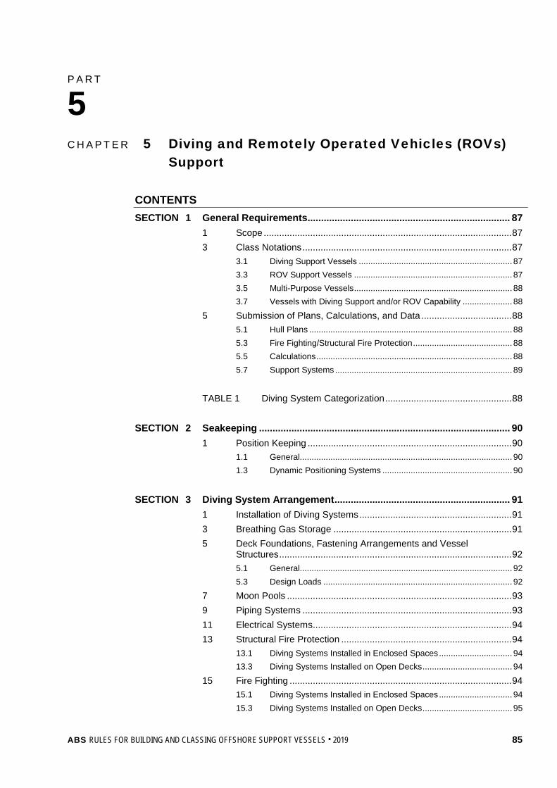
P A R T C h a p t e r 5 : D i v i n g a n d R e m o t e l y O p e r a t e d V e h i c l e s ( R O V s ) S u p p o r t
5 C H A P T E R 5 Diving and Remotely Operated Vehicles (ROVs)
Support
CONTENTS SECTION 1 General Requirements ........................................................................... 87
1 Scope ................................................................................................ 87 3 Class Notations ................................................................................. 87
3.1 Diving Support Vessels ................................................................. 87 3.3 ROV Support Vessels ................................................................... 87 3.5 Multi-Purpose Vessels ................................................................... 88 3.7 Vessels with Diving Support and/or ROV Capability ..................... 88
5 Submission of Plans, Calculations, and Data ................................... 88 5.1 Hull Plans ...................................................................................... 88 5.3 Fire Fighting/Structural Fire Protection .......................................... 88 5.5 Calculations ................................................................................... 88 5.7 Support Systems ........................................................................... 89
TABLE 1 Diving System Categorization ................................................. 88
SECTION 2 Seakeeping ............................................................................................. 90
1 Position Keeping ............................................................................... 90 1.1 General.......................................................................................... 90 1.3 Dynamic Positioning Systems ....................................................... 90
SECTION 3 Diving System Arrangement ................................................................. 91
1 Installation of Diving Systems ........................................................... 91 3 Breathing Gas Storage ..................................................................... 91 5 Deck Foundations, Fastening Arrangements and Vessel
Structures .......................................................................................... 92 5.1 General.......................................................................................... 92 5.3 Design Loads ................................................................................ 92
7 Moon Pools ....................................................................................... 93 9 Piping Systems ................................................................................. 93 11 Electrical Systems ............................................................................. 94 13 Structural Fire Protection .................................................................. 94
13.1 Diving Systems Installed in Enclosed Spaces ............................... 94 13.3 Diving Systems Installed on Open Decks ...................................... 94
15 Fire Fighting ...................................................................................... 94 15.1 Diving Systems Installed in Enclosed Spaces ............................... 94 15.3 Diving Systems Installed on Open Decks ...................................... 95
ABS RULES FOR BUILDING AND CLASSING OFFSHORE SUPPORT VESSELS . 2019 85
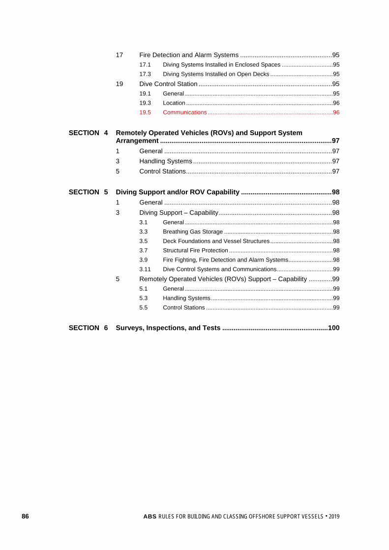
17 Fire Detection and Alarm Systems ................................................... 95 17.1 Diving Systems Installed in Enclosed Spaces ............................... 95 17.3 Diving Systems Installed on Open Decks ...................................... 95
19 Dive Control Station .......................................................................... 95 19.1 General .......................................................................................... 95 19.3 Location ......................................................................................... 96 19.5 Communications ............................................................................ 96
SECTION 4 Remotely Operated Vehicles (ROVs) and Support System
Arrangement ........................................................................................... 97 1 General ............................................................................................. 97 3 Handling Systems ............................................................................. 97 5 Control Stations................................................................................. 97
SECTION 5 Diving Support and/or ROV Capability ................................................ 98
1 General ............................................................................................. 98 3 Diving Support – Capability ............................................................... 98
3.1 General .......................................................................................... 98 3.3 Breathing Gas Storage .................................................................. 98 3.5 Deck Foundations and Vessel Structures ...................................... 98 3.7 Structural Fire Protection ............................................................... 98 3.9 Fire Fighting, Fire Detection and Alarm Systems ........................... 98 3.11 Dive Control Systems and Communications .................................. 99
5 Remotely Operated Vehicles (ROVs) Support – Capability ............. 99 5.1 General .......................................................................................... 99 5.3 Handling Systems .......................................................................... 99 5.5 Control Stations ............................................................................. 99
SECTION 6 Surveys, Inspections, and Tests ........................................................ 100
86 ABS RULES FOR BUILDING AND CLASSING OFFSHORE SUPPORT VESSELS . 2019
P A R T S e c t i o n 1 : G e n e r a l R e q u i r e m e n t s
5 C H A P T E R 5 Diving and Remotely Operated Vehicles (ROVs)
Support
S E C T I O N 1 General Requirements
1 Scope The requirements of this Chapter apply to Offshore Support Vessels intended for unrestricted service which are designed and equipped for supporting diving operations and remotely operated vehicles (ROVs) operations. Diving operations may include but are not limited to diving on, or in the vicinity of, subsea facilities/structures, pipelines and wellheads.
3 Class Notations
3.1 Diving Support Vessels In accordance with Section 1-1-2 of the OSV Rules Supplement to the ABS Rules for Conditions of Classification (Part 1) and 5-1-1/5.1 of these Rules, the Class notation À A1 Offshore Support Vessel (DSV AIR) is to be assigned to vessels intended to support air diving systems (see 5-5-1/Table 1) and complying with the applicable requirements of these Rules.
The Class notation À A1 Offshore Support Vessel (DSV MIXED-GAS) is to be assigned to vessels intended to support mixed-gas diving systems (see 5-5-1/Table 1) and complying with the applicable requirements of these Rules.
The Class notation À A1 Offshore Support Vessel (DSV SAT) is to be assigned to vessels intended to support saturation diving systems (see 5-5-1/Table 1) and complying with the applicable requirements of these Rules.
Vessels that are intended to support multiple diving systems and complying with the applicable requirements of these Rules are to be assigned the Class notation À A1 Offshore Support Vessel (DSV) followed by the appropriate notations for the diving systems. For example, vessels intended to support air and saturation diving systems are to be assigned the Class notation À A1 Offshore Support Vessel (DSV AIR/SAT). Diving Systems installed on diving support vessels are to be classed by ABS or another IACS member Classification Society. The ABS classed diving systems are to be certified in accordance with ABS Rules for Building and Classing Underwater Vehicles, Systems and Hyperbaric Facilities (Underwater Vehicles Rules).
3.3 ROV Support Vessels In accordance with Section 1-1-2 of the OSV Rules Supplement to the ABS Rules for Conditions of Classification (Part 1) and 5-1-1/5.1 of these Rules, the Class notation À A1 Offshore Support Vessel (ROV) is to be assigned to vessels intended to support Remote Operated Vehicle – ROV (see Section 5-5-4) and complying with the applicable requirements of these Rules.
ROVs and their associated support systems (handling systems, control stations, etc.) installed on ROV support vessels are to be classed by ABS or another IACS member Classification Society. ABS Classed ROVs and support components are to meet the requirements of the Underwater Vehicles Rules.
ABS RULES FOR BUILDING AND CLASSING OFFSHORE SUPPORT VESSELS . 2019 87

Part 5 Specialized Services Chapter 5 Diving and Remotely Operated Vehicles (ROVs) Support Section 1 General Requirements 5-5-1
TABLE 1 Diving System Categorization
Parameter Type of Diving System Air Diving System (AIR) Mixed-Gas Diving System
(MIXED-GAS) Saturation Diving System
(SAT) Design / Rated Depth ≤ 190 FSW (57.9 MSW) ≤ 300 FSW (91.4 MSW) ≤ 1500 FSW (457.2 MSW) Diving Duration ≤ 8 hours ≤ 24 hours No restrictions Breathing Gases Compressed Air or
Enriched Air (Nitrox) Heliox, Trimix (Helium
Nitrogen Oxygen) or equivalent
Heliox, Trimix (Helium Nitrogen Oxygen, Helium Hydrogen
Oxygen) or equivalent
3.5 Multi-Purpose Vessels Vessels intended for supporting diving and/or ROV operations as well as other dedicated operations (such as anchor handling, fire fighting, etc.) and complying with the applicable requirements of these Rules are to be assigned the applicable Class notation specified in 5-5-1/3.1 above, followed by the applicable Class notation for the other operations as described in Section 5-1-1.
3.7 Vessels with Diving Support and/or ROV Capability (1 July 2012) Vessels, other than those in 5-5-1/3.1 and 5-5-1/3.3 above, having some diving and/or ROV support capability in addition to their regular service, may be considered and reviewed in accordance with Section 5-5-5 of these Rules, in relation to the specific diving and/or ROV support requirements. Such vessels complying with these requirements may be distinguished in the Record with their assigned notation followed by the designation (DSV Capable) and/or (ROV Capable), such as À A1 Offshore Support Vessel (DSV Capable), with detailed data on the extent of this capability entered into the Record. Such special diving and/or ROV support systems will be subject to annual surveys.
5 Submission of Plans, Calculations, and Data In general, in addition to the plans listed in Section 1-1-4 of the OSV Rules Supplement to the ABS Rules for Conditions of Classification (Part 1), the following plans, calculations and data are to be submitted for review:
5.1 Hull Plans For a list of drawings to be submitted together with the Trim and Stability Booklet for ABS review, please refer to 3-3-A1/17.
5.3 Fire Fighting/Structural Fire Protection • General arrangement defining all spaces on the vessel that surround/enclose diving systems.
• Details on the fire integrity of the surrounding/enclosing spaces.
• List of insulation materials used on surrounding/enclosing spaces including technical data and flammability conditions/restrictions, if any.
• Fire detection/alarm and fire fighting equipment details for the surrounding/enclosing spaces.
5.5 Calculations The following calculations are to be submitted for review:
• Calculations for deck foundations, fastening arrangements and vessel supporting structure in-way of diving systems (See 5-5-3/5).
• Calculations demonstrating adequacy of the vessel’s propulsion system for maintaining station during diving operations.
88 ABS RULES FOR BUILDING AND CLASSING OFFSHORE SUPPORT VESSELS . 2019

Part 5 Specialized Services Chapter 5 Diving and Remotely Operated Vehicles (ROVs) Support Section 1 General Requirements 5-5-1
5.7 Support Systems • Electrical schematics, load analysis, short circuit and coordination study for the vessel’s electrical systems
supplying diving systems.
• General arrangement showing the location of all important electrical equipment for diving systems including main and emergency switchboards, distribution boxes, etc.
• Piping schematics and calculations for the vessel’s piping systems supplying diving systems.
• Arrangement and details of communication systems between the vessel and diving systems.
ABS RULES FOR BUILDING AND CLASSING OFFSHORE SUPPORT VESSELS . 2019 89

P A R T S e c t i o n 2 : S e a k e e p i n g
5 C H A P T E R 5 Diving and Remotely Operated Vehicles (ROVs)
Support
S E C T I O N 2 Seakeeping
1 Position Keeping
1.1 General Dive support vessels are to be capable of maintaining their positions safely during diving operations. The means to maintain position may be a mooring system with anchors or a dynamic positioning system.
1.3 Dynamic Positioning Systems Dynamic positioning systems, when used to maintain the vessel’s position during diving operations, are to comply with the requirements for the class notation DPS-2 or DPS-3 (see the ABS Guide for Dynamic Positioning Systems).
The dive control station and the control station for the dynamic positioning system are to be linked by a communication system and a manually operated alarm system.
90 ABS RULES FOR BUILDING AND CLASSING OFFSHORE SUPPORT VESSELS . 2019

P A R T S e c t i o n 3 : D i v i n g S y s t e m A r r a n g e m e n t
5 C H A P T E R 5 Diving and Remotely Operated Vehicles (ROVs)
Support
S E C T I O N 3 Diving System Arrangement
1 Installation of Diving Systems Diving systems are to be installed in safe areas on a dive support vessel. Safe areas are those areas that are outside hazardous zones as defined in 4-8-4/29.3.
Special consideration will be given on a case-by-case basis for diving systems that may be installed in Zone 2 hazardous zones as defined by the International Electrotechnical Commission’s Publication No.79-10 and Chapter 6 of the IMO MODU code.
Diving systems and breathing gas storage facilities are not be installed in machinery spaces that have machinery not associated with the diving system.
Diving systems are not to be installed in the vicinity of exhausts/ventilation outlets from machinery spaces and galleys.
The diving system is to be located so that the diving operations are not affected by propellers, thrusters or anchors of the diving support vessel.
Diving operations are to be conducted as far away as practicable from the vessel’s overboard discharge outlets/suction inlets in order to keep the diving site free of suction, turbulence and discharge products, which may obscure visibility in the water or might cause skin infections or expose divers to harmful chemicals.
Impressed current system anodes, when installed in the vicinity of diving systems, are to be capable of being switched off during diving operations.
It is recommended that pressure vessels for human occupancy (PVHOs) be are arranged along the longitudinal (fore and aft) direction of the dive support vessel in order to minimize the rolling effect on divers within the PVHOs.
Diving systems are to be installed in spaces or locations that are adequately ventilated and provided with suitable lighting.
When any part of the diving system is located on open decks or similar structures, particular attention is to be given to providing reasonable protection from the sea, icing or any damage which may result from other activities onboard the dive support vessel/offshore facility.
In order to minimize deflections and to obtain satisfactory transfer of heavy loads through the deck foundations, it is recommended that diving systems be installed in-line with the supporting deck structure.
3 Breathing Gas Storage Breathing gas cylinders for diving systems are to be stored on the open deck or in well ventilated enclosed spaces, and away from flammable substances and sources of ignition.
Where the breathing gas cylinders are stored on the open deck, they are to be provided with weather protection (particularly from heavy seas and heat) and are to be effectively protected from mechanical damage. Suitable drainage of the storage area is to be provided.
ABS RULES FOR BUILDING AND CLASSING OFFSHORE SUPPORT VESSELS . 2019 91

Part 5 Specialized Services Chapter 5 Diving and Remotely Operated Vehicles (ROVs) Support Section 3 Diving System Arrangement 5-5-3
The boundaries between enclosed spaces housing the breathing gas cylinders and other enclosed spaces are to be gas tight. Access doors for these enclosed spaces are to open outwards. Suitable drainage of the enclosed spaces is to be provided.
The outlets of relief valves or bursting discs are to be piped-outside the enclosed spaces to the open deck and away from sources of ignition.
Each enclosed space is to be provided with a forced ventilation system capable of providing at least eight air changes per hour based on the gross volume of the space. The ventilation system is to be independent of ventilation systems of other spaces. The ventilation system air is to be drawn from a non-hazardous area. Ventilation system fans are to be of non-sparking construction.
Breathing gas mixtures containing more than 25% Oxygen by volume are to be treated and handled as pure Oxygen. Cylinders with these mixtures are to be stored on the open deck. They are not to be stored below the deck.
When breathing gas mixtures containing less than 25% Oxygen by volume is stored in enclosed spaces, at least two Oxygen analyzers with audio-visual alarms are to be provided. At least one analyzer is to monitor the upper levels of the enclosed space and at least one analyzer is to monitor the lower levels of the enclosed space. These enclosed spaces are to be thoroughly cleaned of hydrocarbons, fat, grease and other debris.
Where the diving support vessel is also used for fire fighting operations, means are to be provided to protect the Oxygen cylinders from heat that may radiate from the fire that is being extinguished.
5 Deck Foundations, Fastening Arrangements and Vessel Structures
5.1 General Diving systems are to be securely attached to the hull structure of the dive support vessel using suitable permanent means of fastening such as welding or bolting. (Lashing is not considered to be a permanent means of fastening).
Deck foundations and fastening arrangements are to permit relative movement of pressure vessels for human occupancy (PVHOs) and large gas storage cylinders due to internal pressure variations that may cause them to expand/contract.
5.3 Design Loads Deck foundations, fastening arrangements and vessel structures in-way of diving systems are to be designed for the following loads:
5.3.1 Acceleration Loads Acceleration loads are not to be less than:
PV = 0.102*[(x – L/70)]W kN (tf)
= 0.102*[(x – L/229.7)]W Lt
PL = PT = 0.5W
where:
PV = vertical force, in kN (tf, Lt)
PL = longitudinal force, in kN (tf, Lt)
PT = transverse force, in kN (tf, Lt)
L = length as per 3-1-1/3.1, in m (ft)
W = supported weight, in kN (tf, Lt)
92 ABS RULES FOR BUILDING AND CLASSING OFFSHORE SUPPORT VESSELS . 2019

Part 5 Specialized Services Chapter 5 Diving and Remotely Operated Vehicles (ROVs) Support Section 3 Diving System Arrangement 5-5-3
The value of “x” is dependent on the location of the center of gravity of the specific component and is to be taken as that given in the table below. The value of “x” at intermediate locations is to be determined by interpolation. L is to be measured from AP to forward.
AP & aft of AP 0.1L 0.2L 0.3L ~ 0.6L 0.7L 0.8L 0.9L FP & forward x = 18 17 16 15 16 17 18 19
Alternatively, accelerations derived from other recognized standards or direct calculations, model tests considering the most serve environmental conditions the vessel is expected to encounter may be considered.
5.3.2 Static Inclination Loads Deck foundations and fastening arrangements for diving system components are to be designed for a static inclination of 30° without exceeding the allowable stresses specified below.
5.3.3 Hydrostatic Testing Loads When it is intended that hydrostatic testing of pressure vessels for human occupancy (PVHO) and other pressure vessels be carried out while they are installed on the dive support vessel, then the deck foundations and fastening arrangements are to be designed for supporting the maximum static load due to the hydrostatic testing, without unacceptable deflections.
5.3.4 Mating Loads When mating operations are to be carried out on the dive support vessel, the deck foundations and fastening arrangements of pressure vessels for human occupancy (PVHO) are to be designed for mating loads. The mating loads are to consider a force of not less than twice the weight of the mating PVHO (diving bell, hyperbaric evacuation unit, etc.) and are to include other applicable loads such as the weight of entrapped mud and water.
5.3.5 Handling System Loads The maximum expected operational loads are to be considered for the design of deck foundations, fastening arrangements and vessel structures in way of handling systems (launch and recovery systems, davits, cranes, etc.) and handling system elements (winches, sheaves, dampers, etc.).
When handling systems are used for handling manned objects such as Diving Bells, Diving Baskets, etc., a dynamic factor of at least 2g vertical, 1g transverse and 1g longitudinal is to be applied. When handling systems are used for handing unmanned objects, a dynamic factor of at least 1.75g vertical, 0.75g transverse and 0.75g longitudinal is to be applied. For permanently installed systems, consideration may be given to lower dynamic factors, when it can be shown that the maximum expected loads are less than those specified above (see 17/7.3.4 of the Underwater Vehicles Rules).
5.3.6 Allowable Stresses Normal Stress = 0.7Y
Shear Stress = 0.4Y
Equivalent stress = 0.8Y
where: Y is the specified minimum tensile yield strength or yield point.
7 Moon Pools (2016) Moon pools, where provided for diving operations, are to meet the requirements in 3-2-2/8.
ABS RULES FOR BUILDING AND CLASSING OFFSHORE SUPPORT VESSELS . 2019 93
Part 5 Specialized Services Chapter 5 Diving and Remotely Operated Vehicles (ROVs) Support Section 3 Diving System Arrangement 5-5-3
9 Piping Systems Piping systems carrying breathing gases under high pressure are not to be arranged inside accommodation spaces, engine rooms or similar compartments.
Piping systems carrying breathing gases are to run as far as practicable apart from electrical cable conduits.
Piping systems containing flammable fluids are not to run through enclosed spaces or open deck areas housing breathing gases.
11 Electrical Systems The electrical installations essential to the safe completion of the diving operations are to be supplied from independent main and emergency sources of electrical power.
The vessel’s main power source may be used to supply normal power to diving systems, provided it has sufficient capacity to simultaneously supply the vessel’s electrical loads as well as the electrical loads of the diving systems. Alternatively, electrical power may be supplied by dedicated self-contained generators.
In the event of failure of the main source of electrical power to the diving system, an independent emergency source of electrical power is to be available for the safe termination of the diving operation. The emergency generator of the dive support vessel may be used as the emergency source of electrical power provided it has sufficient electrical power capacity to supply the diving system and the emergency loads of the dive support vessel/offshore facility at the same time. Alternatively, the emergency source of electrical power may be a dedicated self-contained generator.
Generators that are being used as the emergency source of power for the diving system are to be located outside the machinery spaces of the dive support vessel and as far apart as practicable from other generators being used as the normal source of power for the diving system.
13 Structural Fire Protection
13.1 Diving Systems Installed in Enclosed Spaces Enclosed spaces on dive support vessels housing diving systems are to be separated from adjacent spaces by means of A-60 class bulkheads or decks. All doors between these enclosed spaces and adjacent enclosed spaces are to be of the self-closing type.
Enclosed spaces housing diving systems may be subdivided into additional compartments using A-0 class bulkheads.
Piping and cables penetrating the bulkheads or decks of enclosed spaces are to be routed through mechanical/electrical penetrations meeting the A-60 class standard.
Enclosed spaces housing diving systems are to be provided with a separate forced ventilation system capable of providing at least eight air changes per hour. The air is to be drawn from a non-hazardous area.
13.3 Diving Systems Installed on Open Decks When diving systems are installed on open decks or similar structures that are directly adjacent to Category A machinery spaces, the systems are to be separated from the machinery spaces by A-60 class bulkheads or decks.
15 Fire Fighting
15.1 Diving Systems Installed in Enclosed Spaces Enclosed spaces on dive support vessels are to be provided with manually actuated fixed fire extinguishing systems with a layout that covers the complete diving system. The fixed extinguishing system is to be either a water spray system or gas system approved for use in machinery spaces of Category A and complying with IMO MSC/Circ.848/1267 and FSS Code.
94 ABS RULES FOR BUILDING AND CLASSING OFFSHORE SUPPORT VESSELS . 2019

Part 5 Specialized Services Chapter 5 Diving and Remotely Operated Vehicles (ROVs) Support Section 3 Diving System Arrangement 5-5-3
If a fixed gas extinguishing system is selected, the complete discharge of the extinguishing system in the enclosed space is not to result in a toxic concentration. Extinguishing agents/propellants that are carcinogenic, mutagenic, or teratogenic at the expected concentrations during use are not permitted. Agents/propellants are not to be used in concentrations greater than the cardiac sensitization NOAEL (No Observed Adverse Effect Level) and the ALC (Approximate Lethal Concentration) per IMO MSC/Circ.776.
Means are to be provided for cooling the windows of pressure vessels for human occupancy (PVHOs) installed in enclosed spaces.
Portable fire extinguishers of approved types are to be distributed throughout the enclosed space containing the diving system. One of the portable fire-extinguishers is to be stowed near the entrance to the enclosed space. Spare charges are to be provided on board for 100% of the first ten extinguishers and 50% of the remaining extinguishers installed within the enclosed space.
Enclosed spaces intended for storage of breathing gas cylinders/pressure vessels are to be fitted with a manually actuated fixed water spray system with an application rate of at least 10 liters/m2 per minute of the horizontal projected area, in order to cool and protect such cylinders/pressure vessels during a fire. Alternatively, the enclosed spaces may be fitted with a water-mist system with an application rate of not less than 5 liters/m2 per minute.
15.3 Diving Systems Installed on Open Decks The areas where diving systems are situated on decks or similar structures of dive support vessels are to be equipped with fire extinguishing systems suitable for the locations and areas concerned.
Fire hoses connected to the fire main of the dive support vessel may be considered as providing the necessary protection.
Means are to be provided for cooling the windows of PVHOs installed on open decks or similar structures.
17 Fire Detection and Alarm Systems
17.1 Diving Systems Installed in Enclosed Spaces Enclosed spaces housing diving systems are to be provided with automatic fire detection and alarm systems suitable for the location and area concerned and complying with the requirements of 4-7-3/11.
The loop or group of detectors covering these enclosed spaces is to be independent of those for other spaces.
The fire detection panel is to be located on the vessel’s position control station and is to be provided with repeaters at the dive control station and the engine control room.
17.3 Diving Systems Installed on Open Decks Open decks or similar structures of dive support vessels are to be provided with automatic fire detection and alarm systems suitable for the location and area concerned. Consideration will be given to continuous direct visual/video camera monitoring of the diving system by the dive control station personnel in lieu of fire detection and alarm systems.
19 Dive Control Station
19.1 General (1 July 2012) When diving systems are permanently installed on purpose built vessels, the dive control stations are to meet the requirements of Section 18 of the Underwater Vehicles Rules or to meet the applicable requirements of the IACS member Classification Society that classed the diving system.
When portable diving systems are installed on vessels, the control stations are to comply with the following requirements.
ABS RULES FOR BUILDING AND CLASSING OFFSHORE SUPPORT VESSELS . 2019 95

Part 5 Specialized Services Chapter 5 Diving and Remotely Operated Vehicles (ROVs) Support Section 3 Diving System Arrangement 5-5-3
19.3 Location A dive control station is to be securely fastened at a location close to and in sight of the diving location.
The position of the dive control station is to allow the operations control personnel an overview of all systems and activities associated with the operations of the underwater vehicle and the dive. It is not to be located in hazardous areas.
When selecting the location of the dive control station, ship’s motion or support structure vibrations are to be considered.
19.5 Communications (2019) At a minimum, direct two-way communication is to be provided between the dive control station and:
• Sat control
• Diving bell
• Diver in the water
• Diving system handling positions
• Dynamic positioning room
• Navigation bridge or ship’s command center
• Drilling floor, if applicable
Direct two way communication is to be provided between the Sat Control station and:
• Dive Control
• Each compartment of the Chambers
Automatic recording of communication between the diving bell and the control station is to be possible.
Where more than one dive control and/or underwater vehicle control stations are installed on board, direct communication is to be provided between these control stations.
96 ABS RULES FOR BUILDING AND CLASSING OFFSHORE SUPPORT VESSELS . 2019

P A R T S e c t i o n 4 : R e m o t e l y O p e r a t e d V e h i c l e s ( R O V s ) a n d S u p p o r t S y s t e m A r r a n g e m e n t
5 C H A P T E R 5 Diving and Remotely Operated Vehicles (ROVs)
Support
S E C T I O N 4 Remotely Operated Vehicles (ROVs) and Support System Arrangement
1 General (1 July 2012) A remotely operated vehicle (ROV) is an unmanned unit tethered to a support vessel or structure and designed for underwater viewing, cutting, cleaning or other underwater tasks.
At the request of the owner and where ROVs and their associated support systems (handling systems, control stations, etc.) are Classed by ABS or another IACS member Classification Society, and installed on offshore support vessels in accordance with provisions in this Section under the supervision of the ABS Surveyor, the notation À A1 Offshore Support Vessel (ROV) will be assigned to the vessels, see 5-5-1/3.3.
3 Handling Systems Handling systems of ROVs are to meet the requirements of Section 18 of the Underwater Vehicles Rules or to meet the applicable requirements of the IACS member Classification Society that Classed the ROV system.
The handling systems are to be so arranged as to minimize the possibility of any interference of ROV operations with propellers, thrusters or anchors of the support vessel.
Safe storage location with fastening arrangements is to be provided for ROVs being securely stowed on the support vessel while they are not in operation. Deck foundations, fastening arrangements and support vessel structures for ROV support components are to meet the requirements in 5-5-3/5.
5 Control Stations A ROV control station is to be securely fastened at a location close to and in sight of the ROV launch and recovery location.
A ROV control station is to be provided with hard-wired direct communications with the following positions:
• Vessel’s station control stations
• Any other underwater vehicle control stations
• Control stations for subsea equipment, such as well intervention, etc. operated from the support vessel
ABS RULES FOR BUILDING AND CLASSING OFFSHORE SUPPORT VESSELS . 2019 97

P A R T S e c t i o n 5 : D i v i n g S u p p o r t a n d / o r R O V C a p a b i l i t y
5 C H A P T E R 5 Diving and Remotely Operated Vehicles (ROVs)
Support
S E C T I O N 5 Diving Support and/or ROV Capability (1 July 2012)
1 General Offshore support vessels that comply with 5-5-5/3 of these Rules and have been designed for diving support operations, but the diving system has not been installed on board, are eligible for the class notation À A1 Offshore Support Vessel (DSV Capable). Offshore support vessels that comply with 5-5-5/5 of these Rules and have been designed for remotely operated vehicles (ROVs) support operations, but the ROV and its associated support systems have not been installed on board, are eligible for the class notation À A1 Offshore Support Vessel (ROV Capable).
3 Diving Support – Capability
3.1 General i) The area in which the diving systems and breathing gas storage will be installed is to be defined
and marked on the general arrangement plan of the vessel.
ii) Hazardous areas are to be delineated in accordance with 4-8-4/29.3 based on i) above.
3.3 Breathing Gas Storage Where the breathing gas cylinders are intended to be stored on the open deck, means for weather protection (particularly from heavy seas and heat) and for protection from mechanical damage are to be considered. Suitable drainage of the storage area is to be provided.
3.5 Deck Foundations and Vessel Structures (2016) Deck foundations in way of diving systems are to be designed for the design loads in accordance with 5-5-3/5.3.
Moon pools, where provided for diving operations, are to meet the requirements in 3-2-2/8.
3.7 Structural Fire Protection Structural fire protection arrangements are to comply with the requirements in 5-5-3/13.
3.9 Fire Fighting, Fire Detection and Alarm Systems Where diving systems are intended to be situated on decks or similar structures of dive support vessels, fire hoses connected to the fire main of the dive support vessel are to be available for the locations and areas concerned. Direct visual/video camera monitoring system may be accepted in lieu of fire detection and alarm systems for the locations and areas concerned.
Means are to be provided for cooling the windows of PVHOs installed on open decks or similar structures.
98 ABS RULES FOR BUILDING AND CLASSING OFFSHORE SUPPORT VESSELS . 2019

Part 5 Specialized Services Chapter 5 Diving and Remotely Operated Vehicles (ROVs) Support Section 5 Diving Support and/or ROV Capability 5-5-5
3.11 Dive Control Systems and Communications A location meeting the criteria in 5-5-3/19.3 is to be reserved for the dive control station.
Adequate provision is to be made for the onboard communication system for the future connection and operation of communication devices for additional locations listed in 5-5-3/19.5.
5 Remotely Operated Vehicles (ROVs) Support – Capability At the request of the owner, where ROV support systems installed on offshore support vessels in accordance with the provisions of 5-5-5/5.1 and/or 5-5-5/5.3, the designation À A1 Offshore Support Vessel (ROV Capable) with detailed data on the extent of this capability will be entered into the Record, see 5-5-1/3.7. The ROV systems are subject to annual surveys.
5.1 General The area in which the ROV systems will be installed is to be defined and marked on the general arrangement plan of the vessel.
5.3 Handling Systems The requirements for handling systems of ROVs in 5-5-4/3 are to be met.
5.5 Control Stations A safe location reserved for the ROV control station is to be provided in accordance with 5-5-4/5.
ABS RULES FOR BUILDING AND CLASSING OFFSHORE SUPPORT VESSELS . 2019 99

P A R T S e c t i o n 6 : S u r v e y s , I n s p e c t i o n s , a n d T e s t s
5 C H A P T E R 5 Diving and Remotely Operated Vehicles (ROVs)
Support
S E C T I O N 6 Surveys, Inspections, and Tests
Installation of diving and/or ROV systems on diving and/or ROV support vessels is to be to the satisfaction of the attending Surveyor.
Suitable evidence is to be provided to the Surveyor to verify that diving and/or ROV systems installed on the diving and/or ROV support vessel are Classed by ABS or an IACS member Classification Society.
Upon installation, the diving and/or ROV systems and their support vessel interfaces as well as the interfaces between the diving systems and/or ROV systems installed on the support vessel are to be functionally tested to the satisfaction of the attending Surveyor.
100 ABS RULES FOR BUILDING AND CLASSING OFFSHORE SUPPORT VESSELS . 2019

P A R T C h a p t e r 6 : O i l S p i l l R e c o v e r y
5 C H A P T E R 6 Oil Spill Recovery
CONTENTS SECTION 1 General .................................................................................................. 105
1 Application ...................................................................................... 105 3 Classification ................................................................................... 105
3.1 Oil Spill Recovery – Standby Class 1 .......................................... 105 3.2 Oil Spill Recovery – Standby Class 2 .......................................... 105 3.3 Oil Spill Recovery – Capability Class 1 ....................................... 105 3.4 Oil Spill Recovery – Capability Class 2 ....................................... 106 3.5 Selection of Class ........................................................................ 106 3.7 Administration Requirements ...................................................... 106
5 Submission of Plans ....................................................................... 106 5.1 Plans ........................................................................................... 106 5.3 Supporting Documents ................................................................ 106 5.5 Supporting Calculations............................................................... 107
7 Operating Manual ........................................................................... 107 9 Tests and Trials .............................................................................. 108
9.1 Oil Spill Recovery – Standby ....................................................... 108 9.3 Oil Spill Recovery – Capability .................................................... 108
SECTION 2 Definitions ............................................................................................. 109
1 Accommodation Space ................................................................... 109 3 Recovered Oil ................................................................................. 109 5 Cargo Area ...................................................................................... 109 7 Control Station ................................................................................ 109 9 Hazardous Areas ............................................................................ 109 11 Machinery Space ............................................................................ 109 13 Machinery Spaces of Category A ................................................... 109 15 Pump Room .................................................................................... 110 17 Oil .................................................................................................... 110 19 Oil Recovery Operations ................................................................. 110 21 Service Space ................................................................................. 110
SECTION 3 Hull Construction ................................................................................. 111
1 General ........................................................................................... 111 3 Tank Arrangement .......................................................................... 111
3.1 Location and Separation of Recovered Oil Tanks ....................... 111 3.3 Location of Recovered Oil Tank Openings .................................. 112 3.5 Penetration of Recovered Oil Tanks ............................................ 112
ABS RULES FOR BUILDING AND CLASSING OFFSHORE SUPPORT VESSELS . 2019 101
5 Structural Fire Protection ................................................................ 113 5.1 Fire Integrity of Exterior Bulkheads .............................................. 113 5.3 Openings in Exterior Bulkheads ................................................... 113
7 Spill Coaming .................................................................................. 114 SECTION 4 Machinery Equipment and Systems ................................................... 115
1 General ........................................................................................... 115 3 Machinery and Equipment Installation ............................................ 115
3.1 Exhausts and Intakes................................................................... 115 3.3 Pipes in Hazardous Areas ........................................................... 115 3.5 Pipes and Cables in Recovered Oil Tanks ................................... 115 3.7 Propulsion Shafting ...................................................................... 115 3.9 Non-permanent Equipment .......................................................... 115 3.13 Mechanical Equipment in Hazardous Areas ................................ 116 3.15 Lifting Appliances on Deck and Supports for Oil Recovery
Equipment .................................................................................... 116 5 Recovered Oil Piping Systems ....................................................... 116
5.1 General ........................................................................................ 116 5.3 Recovered Oil Pumps .................................................................. 116 5.5 Relief Valves ................................................................................ 117 5.7 Pressure Gauges ......................................................................... 117 5.9 Piping in Machinery Spaces ......................................................... 117 5.11 Piping in Fuel Oil Tanks ............................................................... 117 5.13 Piping in Ballast Tanks................................................................. 117 5.15 Bow or Stern Discharge ............................................................... 117
7 Recovered Oil Tank Venting Systems ............................................ 117 7.1 General ........................................................................................ 117 7.3 Height .......................................................................................... 118 7.5 Size .............................................................................................. 118 7.7 Location ....................................................................................... 118 7.9 Portable Vent Pipes ..................................................................... 118 7.11 Liquid Level Control ..................................................................... 118
9 Hazardous Areas ............................................................................ 118 9.1 Definitions .................................................................................... 118 9.3 Classification of Areas ................................................................. 119
11 Openings, Access, and Ventilation Conditions Affecting the Extent of Hazardous Zones ............................................................ 119 11.1 Enclosed Space with Direct Access to any Zone 1 Location ....... 120 11.3 Enclosed Space with Direct Access to any Zone 2 Location ....... 120 11.5 Enclosed Space with Access to any Zone 1 Location .................. 121 11.7 Hold-back Devices ....................................................................... 122
13 Ventilation Systems ........................................................................ 122 13.1 General ........................................................................................ 122 13.3 Pump Room Ventilation ............................................................... 122 13.5 Ventilation of Other Hazardous Areas.......................................... 122 13.7 Ventilation of Non-hazardous Areas ............................................ 123 13.9 Ventilation Alarms ........................................................................ 123
102 ABS RULES FOR BUILDING AND CLASSING OFFSHORE SUPPORT VESSELS . 2019

15 Machinery Installations in Hazardous Areas................................... 123 17 Fire Extinguishing Systems and Equipment ................................... 123
17.1 Deck Area .................................................................................... 123 17.3 Pump Rooms ............................................................................... 124 17.5 Gas Measuring Instruments ........................................................ 124
19 Oil Pollution Prevention Measures .................................................. 124 21 Other Requirements ........................................................................ 124 FIGURE 1 Hazardous Zones .................................................................. 120 FIGURE 2 Hazardous Zones .................................................................. 121 FIGURE 3 Hazardous Zones .................................................................. 122
SECTION 5 Oil Spill Recovery – Capability Class 1 ............................................. 125
1 General ........................................................................................... 125 3 Oil Spill Recovery – Capability ........................................................ 125
3.1 General........................................................................................ 125 3.3 Operating Manual ........................................................................ 125 3.5 Hull Construction ......................................................................... 125 3.7 Machinery Equipment and Systems ............................................ 125
SECTION 6 Oil Spill Recovery – Standby Class 2 ................................................ 126
1 General ........................................................................................... 126 3 Plans and Operating Manual .......................................................... 126 5 Hull Construction ............................................................................. 126
5.1 Separation of Recovered Oil Tanks ............................................. 126 5.3 Penetration of Recovered Oil Tanks ............................................ 127 5.5 Structural Fire Protection ............................................................. 127
7 Machinery Equipment and Systems ............................................... 127 7.1 Machinery and Equipment Installation ......................................... 127 7.3 Recovered Oil Piping Systems .................................................... 127 7.5 Recovered Oil Tank Venting Systems ......................................... 127 7.7 Hazardous Areas ......................................................................... 127 7.9 Ventilation Systems ..................................................................... 127 7.11 Machinery Installations in Hazardous Areas ................................ 127 7.13 Fire Extinguishing Systems and Equipment ................................ 127
SECTION 7 Oil Spill Recovery – Capability Class 2 ............................................. 128
1 General ........................................................................................... 128 3 Plans and Operating Manual .......................................................... 128 5 Hull Construction ............................................................................. 128
5.1 Recovered Oil Storage Tanks ..................................................... 128 5.3 Separation of Recovered Oil Tanks ............................................. 128 5.5 Location of Recovered Oil Tank Openings .................................. 129 5.7 Penetration of Recovered Oil Tanks ............................................ 129 5.9 Structural Fire Protection ............................................................. 129
ABS RULES FOR BUILDING AND CLASSING OFFSHORE SUPPORT VESSELS . 2019 103
7 Machinery Equipment and Systems ............................................... 129 7.1 Machinery and Equipment Installation ......................................... 129 7.3 Recovered Oil Piping Systems .................................................... 129 7.5 Recovered Oil Tank Venting Systems ......................................... 129 7.7 Hazardous Areas ......................................................................... 129 7.9 Ventilation Systems ..................................................................... 130 7.11 Machinery Installations in Hazardous Areas ................................ 130 7.13 Fire Extinguishing Systems and Equipment ................................. 130
104 ABS RULES FOR BUILDING AND CLASSING OFFSHORE SUPPORT VESSELS . 2019

P A R T S e c t i o n 1 : G e n e r a l
5 C H A P T E R 6 Oil Spill Recovery
S E C T I O N 1 General
1 Application While adapting offshore support vessels for the carriage of recovered oil from a spill poses some potential hazards similar to oil tankers, it is recognized that these vessels are not likely to be originally designed to meet all the requirements of oil tankers. In consideration of the intended oil recovery services of these vessels, particular attention has been paid to the stability and floatability of the vessels in all relevant operating conditions including ballasting, safety against potential fire and explosion during handling, storage and transportation of recovered oil from a spill on moderate sea conditions, structural support of oil recovery equipment during oil recovery operations, and available electrical power supply to oil recovery equipment intended to be used during oil recovery operations. The purpose of this Chapter is to stipulate the minimum requirements for ABS classification ensuring that such vessels are suitably designed to carry out oil recovery operations. The Owner assumes the responsibility of operating the vessel in a safe manner with suitably trained personnel onboard.
The requirements of these Rules apply to the design, construction, ship’s equipment and operation of offshore support vessels that may be employed occasionally to recover oil having any flash point, from a spill in emergency situations. As such, these vessels may be equipped to handle, store and transport recovered oil.
3 Classification
3.1 Oil Spill Recovery – Standby Class 1 (1 July 2012) In accordance with 1-1-2/11.1 of the OSV Rules Supplement to the ABS Rules for Conditions of Classification (Part 1), the classification À A1 Offshore Support Vessel (OSR-S1) will be assigned to offshore support vessels built in compliance with these requirements for recovery of oil of unknown flash points and outfitted for the same in accordance with Sections 5-6-3 and 5-6-4 and other relevant sections of these Rules, and approved for oil recovery service at the assigned freeboard.
3.2 Oil Spill Recovery – Standby Class 2 (1 July 2012) In accordance with 1-1-2/11.3 of the OSV Rules Supplement to the ABS Rules for Conditions of Classification (Part 1), the classification À A1 Offshore Support Vessel (OSR-S2) will be assigned to offshore support vessels built in compliance with these requirements for recovery of oil having a flash point exceeding 60°C (140°F) and outfitted for the same in accordance with Section 5-6-6 and other relevant sections of these Rules, and approved for oil recovery service at the assigned freeboard.
3.3 Oil Spill Recovery – Capability Class 1 (1 July 2012) In accordance with 1-1-2/11.5 of the OSV Rules Supplement to the ABS Rules for Conditions of Classification (Part 1), the classification À A1 Offshore Support Vessel (OSR-C1) will be assigned to offshore support vessels built in compliance with these requirements for recovery of oil of unknown flash points but not outfitted for the same in accordance with Section 5-6-5 and other relevant sections of these Rules, and approved for oil recovery service at the assigned freeboard.
ABS RULES FOR BUILDING AND CLASSING OFFSHORE SUPPORT VESSELS . 2019 105

Part 5 Specialized Services Chapter 6 Oil Spill Recovery Section 1 General 5-6-1
3.4 Oil Spill Recovery – Capability Class 2 (1 July 2012) In accordance with 1-1-2/11.7 of the OSV Rules Supplement to the ABS Rules for Conditions of Classification (Part 1), the classification À A1 Offshore Support Vessel (OSR-C2) will be assigned to offshore support vessels built in compliance with these requirements for recovery of oil having a flash point exceeding 60°C (140°F) but not outfitted for the same in accordance with Section 5-6-7 and other relevant sections of these Rules, and approved for oil recovery service at the assigned freeboard.
3.5 Selection of Class It is the responsibility of the Owner to select the class most suitable for the intended service and ensure that the vessel is operated in a safe environment with respect to the risk of fire and explosion.
3.7 Administration Requirements Requirements additional to those given in this Chapter may be imposed by the National Administration with whom the vessel is registered or by the Administration within whose territorial jurisdiction the vessel is intended to operate.
Approval of structural fire protection, fire extinguishing equipment and/or stability of the vessel by a National Administration, in accordance with requirements equivalent to those by class, may be considered as complying with the class requirements provided such approval can be satisfactorily documented.
5 Submission of Plans In addition to the plans required to be submitted by Section 1-1-4 of the OSV Rules Supplement to the ABS Rules for Conditions of Classification (Part 1), the following additional plans, supporting documents, and calculations are to be submitted in the same manner.
5.1 Plans • Plans and particulars of recovered oil tanks indicating access.
• Structural and general arrangement plans indicating the location, support and fastening arrangements of oil recovery and handling equipment.
• Plan showing arrangement of structural fire protection and location, controls and particulars of fire extinguishing systems and fire safety equipment. (See 5-6-1/3.7)
• Diagrammatic plans of piping systems for handling recovered oil. These plans are to be accompanied by lists of material giving size, wall thickness, maximum working pressure and material of all pipes and the type, size, pressure rating and material of valves and fittings.
• Diagrammatic plans of recovered oil tank venting arrangements including the position of vent outlets.
• Diagrammatic plans of recovered oil heating systems, if installed.
• Plans showing hazardous locations and electrical equipment in these locations together with a listing of equipment manufacturers and model numbers and evidence of certification for explosion-proof, intrinsically-safe and pressurized equipment. Also, wiring plans, installation instructions and certification agency restrictions for intrinsically-safe systems.
• Plans showing electrical power supply, protection and cabling for oil recovery equipment.
• Plans showing hazardous areas and spaces including the arrangement of ventilating systems for all hazardous areas along with complete particulars of the ventilating system such as capacities of fans, number of complete changes of air per hour, air flows, areas subject to positive or negative pressure, and location and direction of opening of self-closing doors.
5.3 Supporting Documents • Detailed specifications for gas detection/measuring equipment.
• Detailed Operations and Procedures Manual
106 ABS RULES FOR BUILDING AND CLASSING OFFSHORE SUPPORT VESSELS . 2019

Part 5 Specialized Services Chapter 6 Oil Spill Recovery Section 1 General 5-6-1
5.5 Supporting Calculations • Load analysis of structural support in way of deck equipment during oil recovery operations in at least
moderate sea conditions.
• Electrical load analysis considering the use of oil recovery equipment during oil recovery operations.
• Stability analysis considering all relevant operational conditions including ballasting. (See 5-6-1/3.7)
7 Operating Manual It is incumbent upon the Owner to provide information, instructions, data and crew training for the oil recovery operations of the vessel to help assure that the loadings and operational limits upon which the vessel is designed and classification is based are not exceeded. An approved Operating Manual detailing operational and maintenance procedures, equipment and capacity data, and particulars on operation of the vessel during oil recovery mode of operations is to be placed aboard the vessel for the guidance of the operating personnel. The Operating Manual is to be submitted for review by ABS solely to ensure that the information included within is consistent with the design information and limitations considered in the vessel’s classification. ABS is not responsible for the operation of the vessel. The vessel is to be operated during oil recovery mode of operation in accordance with this approved Operating Manual.
The Operating Manual is, in general, to give information regarding the following:
i) Arrangement and equipment
• Tank arrangement with venting systems
• Recovered oil transfer system
• Gas measuring instruments
• Gas detection systems, if installed
• List of oil response equipment and supplies
ii) Oil Recovery Operations and Procedures verifying that all equipment installed in hazardous locations and/or transferred onboard are certified for use in gas-hazardous atmosphere (see 5-6-4/3.11)
• Instructions regarding the use of non-certified electrical equipment (see 5-6-4/3.11)
• Changing-over to low sea suctions for all sea water cooling pumps and fire pumps
• Hook-up and equipment deployment
• Tank filling procedures
• Heating of recovered oil, if applicable
• Discharging of recovered oil
• List of spaces and equipment that may be required to be secured
• List of deadlights that may be required to be secured
• Recovered oil piping and venting configuration instructions
• Space specific ventilation requirements
• Storage location and use of portable gas detection/measuring instruments
• Installation of spill coamings
ABS RULES FOR BUILDING AND CLASSING OFFSHORE SUPPORT VESSELS . 2019 107

Part 5 Specialized Services Chapter 6 Oil Spill Recovery Section 1 General 5-6-1
iii) Safety Instructions
• Fire fighting
• Guidelines regarding safe distance from an oil spill source including specifying conditions when to withdraw the vessel from oil recovery operations.
• Gas measurements during operation (on open deck and in spaces where gas might accumulate)
• Actions to be taken if gases are detected in enclosed spaces (cleaning, ventilation, emptying of adjacent tanks, etc.)
• Precautions against overfilling of tanks
iv) Cleaning and gas-freeing of tanks and pipes
v) Stability in all relevant operational conditions including ballasting guidance.
9 Tests and Trials
9.1 Oil Spill Recovery – Standby During sea trials, the transfer procedures to oil recovery mode of operation for the vessel are to be simulated demonstrating the vessel is suitable for the intended service. The arrangements and equipment referred to in Sections 5-6-3 and 5-6-4 are to be examined and tested to the satisfaction of the attending Surveyor upon completion of the installation and, thereafter, annually on board the vessel.
9.3 Oil Spill Recovery – Capability (2014) Upon completion of installation, the arrangements and equipment referred to in Section 5-6-5 are to be examined and tested to the satisfaction of the attending Surveyor. During sea trials and thereafter annually, the attending Surveyor is to verify the vessel is in compliance with the operation manual and general arrangement plan, and in particular:
i) Area in which the oil recovery equipment will be installed,
ii) Tanks to be used for recovered oil,
iii) Designation of hazardous areas, and
iv) Oil recovery equipment to be used, its location, and deployment and stowage procedures.
Oil recovery equipment stored ashore is to be maintained by the Operator and be readily available for use.
108 ABS RULES FOR BUILDING AND CLASSING OFFSHORE SUPPORT VESSELS . 2019
P A R T S e c t i o n 2 : D e f i n i t i o n s
5 C H A P T E R 6 Oil Spill Recovery
S E C T I O N 2 Definitions
The following definitions of terms are to be understood (in the absence of other specifications) where they appear in this Chapter.
1 Accommodation Space Accommodation Spaces are those spaces used for public spaces, corridors, laboratories, cabins, offices, hospitals, game and hobby rooms, pantries containing no cooking appliances, and similar spaces.
3 Recovered Oil Spilled oil that has been removed from the marine environment and includes mixtures of oil and water.
5 Cargo Area The Cargo Area is that part of the vessel that contains recovered oil tanks, slop tanks and recovered oil pump rooms including cofferdams, ballast and void spaces adjacent to recovered oil tanks and also deck areas throughout the entire length and breadth of the part of the vessel above the aforementioned spaces.
7 Control Station Control Stations are those spaces in which the vessel’s radio or main navigation equipment or the emergency source of power is located or where the fire recording or fire control equipment is located.
9 Hazardous Areas Hazardous Areas are areas where flammable or explosive gases or vapors are normally present or likely to be present. The flammable or explosive atmosphere may be expected to exist continuously or intermittently. See 5-6-4/9.
Safe areas are areas that are not hazardous areas.
11 Machinery Space Machinery Spaces are those spaces and trunks to such spaces which contain propelling machinery, boilers, oil fuel units, steam and internal combustion engines, generators and major electrical machinery, oil filling stations, thermal oil heaters, refrigerating, stabilizing, ventilation and air conditioning machinery.
13 Machinery Spaces of Category A Machinery Spaces of Category A are those spaces and trunks to such spaces which contain either:
i) Internal combustion machinery used for main propulsion
ii) Internal combustion machinery used for purposes other than main propulsion where such machinery has in the aggregate a total power output of not less than 375 kW (500 hp)
iii) Any oil-fired boiler or oil fuel unit, or any oil-fired equipment other than boiler, such as inert gas generator, incinerator, waste disposal units, etc.
ABS RULES FOR BUILDING AND CLASSING OFFSHORE SUPPORT VESSELS . 2019 109
Part 5 Specialized Services Chapter 6 Oil Spill Recovery Section 2 Definitions 5-6-2
15 Pump Room Pump Rooms are those spaces that contain recovered oil transfer pumps, manifolds, separators or any other recovered oil handling equipment.
17 Oil The term Oil refers to petroleum or petroleum products having flash points at or below 60°C (140°F), closed cup test, and specific gravity of not over 1.05, except where specifically indicated as oil having a flash point above 60°C (140°F).
19 Oil Recovery Operations The term Oil Recovery Operations refers to the process used to contain and remove spilled oil from the sea to storage onboard the offshore support vessel. The process also includes the removal of the recovered oil from onboard storage to a disposal facility.
21 Service Space Service Spaces are those spaces used for galleys, pantries containing cooking appliances, lockers, store rooms, workshops other than those forming part of the machinery spaces, and similar spaces and trunks to such spaces.
110 ABS RULES FOR BUILDING AND CLASSING OFFSHORE SUPPORT VESSELS . 2019

P A R T S e c t i o n 3 : H u l l C o n s t r u c t i o n
5 C H A P T E R 6 Oil Spill Recovery
S E C T I O N 3 Hull Construction
1 General Oil spill recovery vessels are to be constructed of steel.
The vessel is to be provided with safe working areas on deck for handling of hoses and oil recovery equipment during oil recovery operations. Working areas are to be provided with adequate lighting, hand-rails and gratings or other non-slip surfaces.
The vessel is to be provided with storage tanks for recovered oil. Tanks used for the storage of liquid mud may be used for the storage of recovered oil. The coating used in recovered oil storage tanks is to be of an oil and dispersion resistant type.
Bridge visibility is to easily permit the monitoring of the oil recovery operations on deck and in the water. Alternatively, special consideration will be given to systems providing equivalent bridge visibility.
3 Tank Arrangement
3.1 Location and Separation of Recovered Oil Tanks 3.1.1 General (1 July 2012)
Oil spill recovery vessels are not required to have double hulls.
Where double bottoms are fitted to comply with any applicable regulation or other purposes, they are to be fitted between the peaks or as near thereto as practicable. The double bottom is not be lower at any point than a plane parallel with the keel line and situated at a height not less than B/20 measured from the keel line, but in no case less than 0.76 m (2.5 ft) and need not exceed 2 m (6.6 ft).
Where wing tanks are located at a distance inboard of the molded line of the side shell plating, this distance is to be nowhere less than 600 mm to permit easy access for inspection.
The minimum size of the access openings to the double bottoms and wing tanks, where fitted, is to be at least 380 mm × 585 mm (15 in. × 23 in.) and circular openings to be at least 457 mm (18 in.).
3.1.2 Separation of Recovered Oil Tanks i) Tanks for recovered oil are not to be located below machinery spaces, service spaces,
control stations and accommodation spaces.
ii) Tanks for recovered oil may be located forward or aft of machinery spaces, service spaces, control stations and accommodation spaces. Recovered oil tanks are to be isolated from such spaces by means of a cofferdam. For the purposes of this requirement, void spaces, pump rooms, fuel oil tanks and compartments arranged solely for ballast may be considered cofferdams. For easy access, the minimum width of the cofferdam is not to be less than 600 mm.
ABS RULES FOR BUILDING AND CLASSING OFFSHORE SUPPORT VESSELS . 2019 111

Part 5 Specialized Services Chapter 6 Oil Spill Recovery Section 3 Hull Construction 5-6-3
iii) Where it is impractical to meet the cofferdam requirement in ii) above, considerations may be granted in the case of other machinery spaces (See Note below). A cofferdam will not be required between the recovered oil tanks and other machinery spaces, provided the following items are met:
a) The bulkhead plating/tank side wall is to be continuous through all joining structures to the top of the tank. Full penetration welding is required at the top of the tank and the contiguous boundaries.
b) The common tank bulkhead/tank side wall is to be readily accessible under normal conditions for inspection.
c) The machinery space adjacent to the recovered oil tanks is to be provided with forced power ventilation system as follows:
• At least twenty (20) air changes per hour, based on the gross volume of the space
• The system is to be operated at all times whenever recovered oil is carried in the tanks. This is to be clearly indicated in the Operating Manual.
• The ventilation system is to be designed and arranged with redundancy such that at least 100% ventilation system is still available after a single failure in any part of the system.
• Fitted with alarms to indicate ventilation failure
• Fitted with non-sparking fans either with the uncertified motor outside of the ventilation duct or with a certified explosion proof motor located within the duct
d) No penetrations that create a source of hazardous vapor or oil release are allowed through the common tank boundary bulkhead. Sources of hazardous vapor or oil include any openings, screwed and flanged pipe connections, valves, pumps, stuffing boxes, etc. All welded pipe connections are not considered sources of hazardous vapor or oil.
e) The tanks are to be hydrostatically tested at the Special Surveys.
f) The common tank bulkhead is to be gauged at Intermediate and Special Surveys. Note: 5-6-3/3.1.2iii) above does not apply to Machinery Spaces of Category A, service spaces, control
stations or accommodation spaces. Recovered oil tanks are to be isolated from such spaces by means of a cofferdam.
3.3 Location of Recovered Oil Tank Openings Openings from recovered oil storage tanks including sounding pipes, vents and hatches are not to be located in enclosed spaces. For the purposes of this requirement, spaces open on one side only are to be considered enclosed.
3.5 Penetration of Recovered Oil Tanks Electrical cables are not to pass through recovered oil tanks unless enclosed within an oil tight trunk or equivalent.
Piping not related to the transfer of recovered oil is not to pass through recovered oil tanks unless the piping is made of steel, Extra-Heavy (see 4-6-1/3.9) and of all welded construction, without valves, flanges, fittings or take-down joints.
112 ABS RULES FOR BUILDING AND CLASSING OFFSHORE SUPPORT VESSELS . 2019

Part 5 Specialized Services Chapter 6 Oil Spill Recovery Section 3 Hull Construction 5-6-3
5 Structural Fire Protection (1 July 2012)
5.1 Fire Integrity of Exterior Bulkheads For superstructures and deck houses enclosing accommodation and machinery spaces, the exterior bulkheads facing the cargo area and side bulkheads within a distance of 3 m (10 ft) from the end bulkhead facing the cargo area are to be of steel construction and insulated, up to the underside of the deck of the navigation bridge, to “A-60” standard as defined in Chapter II-2/Regulation 3 of the International Convention for the Safety of Life at Sea (SOLAS) 1974, as amended with the exception of the following:
i) Insulation to “A-0” standard is acceptable provided the bulkheads are protected by a fixed water-spray system in accordance with 5-4-3/9.3 and 5-4-3/9.5 with a minimum water capacity of 10 liters/minute/m2 (0.25 gpm/ft2).
ii) Insulation to “A-0” standard is acceptable without a water-spray system provided the bulkheads are at least one deck above the cargo area and are at least 10 meters (33 ft) measured horizontally away from a vertical plane of the recovered oil tanks and sources of oil or vapor release (such as tank vents, valves, flanges, and fittings).
Access doors and closing appliances for openings are to meet the same requirements as the bulkhead.
5.3 Openings in Exterior Bulkheads 5.3.1 Accommodation Spaces, Service Spaces, Control Spaces, and Machinery Spaces
i) Accesses, including those in the first tier on the main deck, to accommodation spaces, service spaces, control stations and machinery spaces may face the cargo area and/or be located within the above limits provided they are fitted with two doors, such that the door in the exterior bulkhead is weathertight and has a fire rating equivalent to the boundary in which it is installed and the interior door is self-closing, gastight, with no hold-back devices. The doors are to be spaced apart at least a distance that prevents an individual from opening both doors simultaneously. A notice is to be affixed to each side of each door to the effect that only one door is to be open at a time. Where the double door arrangement is located in a hazardous area, the hazardous area and ventilation requirements for an air lock apply. See 5-6-4/11.5.
ii) Access doors, air inlets and openings to accommodation spaces, service spaces, control stations and machinery spaces may face the cargo area and/or be located within the above limits provided they are located at least one deck above the cargo area and are at least 3 meters (10 feet) measured horizontally away from a vertical plane of the recovered oil tanks and sources of oil or vapor release.
iii) Navigation bridge doors and windows may face the cargo area and/or be located within the above limits provided they are capable of rapidly and efficiently being made gas tight.
5.3.2 Accesses and Openings Not Needed During Oil Recovery Operations Accesses and ventilation openings for spaces containing essential equipment are to be available for use at all times. However, accesses and openings not needed during oil recovery operations may be within the limits of 5-6-3/5.3.1 provided the arrangements comply with the following:
i) Access doors are self-closing gas-tight, secured (i.e., kept closed), and fitted with signs indicating that the doors are to remain closed during oil recovery operations. In addition, the doors are to have a fire rating equivalent to the boundary in which they are installed.
ii) All access and means of escape otherwise required by the Rules are met without the use of the secured access doors.
iii) Closing devices for openings other than access doors are gas-tight, secured (i.e., kept closed), and fitted with signs indicating that the openings are to remain closed during oil recovery operations. In addition, the closing devices are to have a fire rating equivalent to the boundary in which they are installed.
iv) The oil recovery operating manual is to clearly indicate the procedure necessary to secure the accesses, openings, and/or the space. Also, see 5-6-4/3.11.
ABS RULES FOR BUILDING AND CLASSING OFFSHORE SUPPORT VESSELS . 2019 113

Part 5 Specialized Services Chapter 6 Oil Spill Recovery Section 3 Hull Construction 5-6-3
5.3.3 Other Spaces and Locations i) Portlights and windows fitted in locations other than the navigation bridge may face the
cargo area and/or be located within the limits of 5-6-3/5.3.1 provided they are of the fixed (non-opening) type. They are to be fitted with deadlights constructed of steel or other equivalent material, which must be secured during oil recovery operations.
ii) Bolted plates for the removal of machinery may face the cargo area and/or be fitted within the limits of 5-6-3/5.3.1.
5.3.4 Hazardous Areas and Ventilation See 5-6-4/9 and 5-6-4/11 for hazardous area requirements and 5-6-4/13 for ventilation opening requirements which are to be applied independently of 5-6-3/5.3.
7 Spill Coaming (1 July 2012) Oil handling areas and equipment on deck are to be provided with a coaming around all pumps, transfer flanges and other connections where leakage may be expected. Each coaming is to be adequately sized to contain deck spills and prevent recovered oil from entering accommodation, machinery, control and service spaces or passing overboard. The coaming is to have a height of at least 150 mm (6 in.).
Where drains are provided for the coaming, closing devices for these drains are to be permanently attached.
Spill coamings may be of the removable type. Removable coamings are to be constructed of rigid, non oil-absorbent material, leak proof, and can be temporarily fixed to the vessel’s structure.
114 ABS RULES FOR BUILDING AND CLASSING OFFSHORE SUPPORT VESSELS . 2019

P A R T S e c t i o n 4 : M a c h i n e r y E q u i p m e n t a n d S y s t e m s
5 C H A P T E R 6 Oil Spill Recovery
S E C T I O N 4 Machinery Equipment and Systems
1 General Machinery, equipment, electrical systems, piping and fire fighting systems for oil spill recovery vessels are to be in accordance with Part 4 of these Rules and the following additional requirements.
Oil recovery equipment and independent power-packages are to be permanently installed or stored on board the vessel ready to be installed for use.
3 Machinery and Equipment Installation
3.1 Exhausts and Intakes For machinery and equipment exhausts and intakes, refer to 5-6-4/15.
3.3 Pipes in Hazardous Areas Exhaust pipes or any other pipes with surface temperatures exceeding 220°C (428°F) are not to pass through gas hazardous areas.
3.5 Pipes and Cables in Recovered Oil Tanks For piping or cables which pass through tanks for recovered oil, refer to 5-6-3/3.5.
3.7 Propulsion Shafting Where machinery spaces are located forward of recovered oil storage tanks, as permitted by 5-6-3/3.1, propulsion shafting is not to be led through the tanks and is to be effectively grounded.
3.9 Non-permanent Equipment 3.9.1 Power Supply
The arrangement of power supply to non-permanent oil skimming and pumping equipment is as far as practicable to be permanently installed. Power outlets are to be arranged from a connection box provided with a means to prevent disconnection of the portable cable unless power has been removed from the cable (i.e., a door with interlock switch). The supply from the main switchboard to the connection box is to be permanently installed and provided with a separate switchgear with short-circuit and overcurrent protection. These boxes are to be located at easily accessible locations outside of hazardous areas and in such a manner that portable cables are not carried through doors or portlights leading from the working deck area to machinery or accommodation spaces.
3.9.2 Oil Recovery Equipment Non-permanent oil recovery equipment and independent power-packages are to be of the certified safe type and suitable for use in hazardous areas.
ABS RULES FOR BUILDING AND CLASSING OFFSHORE SUPPORT VESSELS . 2019 115

Part 5 Specialized Services Chapter 6 Oil Spill Recovery Section 4 Machinery Equipment and Systems 5-6-4
3.11 Electrical Equipment Not Intended To Be Used During Oil Recovery Operations Electrical equipment located in hazardous locations that is not intended to be used during oil recovery operations and does not meet 4-8-3/13 (for example, equipment not certified intrinsically safe, pressurized enclosure, or explosion proof) may be permitted, provided the location is considered hazardous only during oil recovery operations and the arrangements meet the following requirements.
i) The electrical equipment is considered nonessential (see 4-8-1/7.3.3 for primary essential and secondary essential services) and is not to be used during oil recovery operations.
ii) A detailed list of such equipment in each hazardous area is to be submitted for review.
iii) The electrical equipment as submitted for review in item ii) above is to be arranged so that it cannot be energized when any oil recovery equipment is energized. Once deenergized, specific action by the crew is required to reenergize the equipment. Instruction plates are to be placed at the respective switches.
iv) The oil recovery Operating Manual is to clearly indicate the following:
a) The systems that are deenergized during oil recovery operations and the procedure to be followed.
b) The instructions and procedures to be followed relative to the cleaning and gas freeing of the oil recovery tanks in order to reset the electrical equipment to its original state after oil recovery operations are completed.
3.13 Mechanical Equipment in Hazardous Areas All mechanical equipment for use in hazardous areas during oil recovery operations is to be certified for operation in gas-hazardous atmosphere (see 5-6-4/15).
3.15 Lifting Appliances on Deck and Supports for Oil Recovery Equipment (1 July 2012) Lifting appliances such as masts and cranes intended to be used during oil recovery operations are to be designed and constructed to an acceptable standard, code of practice or satisfy, but need not be certified to, the applicable requirements of the ABS Lifting Appliances Guide in addition to the following:
i) The dynamic loads due to the vessel’s motions are to be considered.
ii) The scantlings of the supporting structures for lifting appliances are to comply with 5-9-3/7.
iii) The calculations for the strength of the supporting structures of lifting appliances for oil recovery equipment may be carried out assuming the oil recovery operations are being conducted in moderate sea conditions.
5 Recovered Oil Piping Systems
5.1 General A fixed recovered oil transfer system is to be provided and arranged to permit simultaneous filling and discharging operations. Piping may consist of movable pipe sections with suitable flanged connections.
Piping connections of systems not related to the oil recovery operations are to be provided with spool piece and blanking arrangements. The blanking devices are to be fitted to the nearest detachable pipe connections at the tank.
5.3 Recovered Oil Pumps (2015) Recovered oil pumps are to be so designed as to minimize the danger of sparking. Care is to be taken in installation of the pumps to prevent leaks at the stuffing box. Where the shafts pass through gastight bulkheads, flexible couplings are to be provided in shafts between pumps and prime movers, and stuffing boxes which can be lubricated from outside the pump room are to be fitted at the bulkheads. The seal parts of the glands are to be of non-sparking construction.
116 ABS RULES FOR BUILDING AND CLASSING OFFSHORE SUPPORT VESSELS . 2019

Part 5 Specialized Services Chapter 6 Oil Spill Recovery Section 4 Machinery Equipment and Systems 5-6-4
5.5 Relief Valves A relief valve of suitable type is to be installed in the discharge of each recovered oil pump and piped back to the suction. Such valves need not be fitted when the system is served only by centrifugal pumps so designed that the pressure delivered cannot exceed that for which the piping is designed.
5.7 Pressure Gauges One pressure gauge for each recovered oil transfer pump is to be located at the pump discharge and, where the pumps are operated by engines external to the pump room, additional gauges are to be provided which are to be visible from the operating station.
5.9 Piping in Machinery Spaces Recovered oil transfer systems are not to pass through machinery spaces except for runs of steel, Extra-Heavy (see 4-6-1/3.9), all welded pipe which are to be provided with a positive closing valve, located outside the machinery space and operable from an accessible location on the open deck, to stop the flow of oil in the event of a fire or leak.
Recovered oil piping system components, such as pumps, manifolds, valves, flanges, slip-joints and other sources of vapor leakage are not to be located within machinery spaces.
5.11 Piping in Fuel Oil Tanks Recovered oil piping is not to pass through fuel oil tanks unless it is steel, Extra-Heavy (see 4-6-1/3.9), all welded pipe without valves, flanges, fittings, or take-down joints.
5.13 Piping in Ballast Tanks Recovered oil piping passing through ballast tanks is to be made of steel, Extra-Heavy (see 4-6-1/3.9) and all welded pipe; special consideration will be given to ferrous materials having corrosion resistant properties. Provisions are to be made for expansion of the piping within the tank.
5.15 Bow or Stern Discharge (1 July 2012) Where bow or stern discharge connections are provided, cargo lines forward or aft of the cargo area are to be led outside accommodation spaces, service spaces, machinery spaces and control stations. Pipe joints outside the cargo area are to be welded except for connections to the manifold or equipment.
The cargo discharge lines are to be clearly identified and provided with means to segregate them from the cargo main line when not in use. The segregation is to be achieved by either two valves, located in the cargo area, which can be locked in the closed position, and fitted with means to detect leakage past the valves; or by one valve together with another closing device providing an equivalent standard of segregation, such as a removable spool piece or spectacle flange.
The discharge connection is to be fitted with a shut-off valve and a blank flange. The blank flange may be omitted if an equivalent means of closing is incorporated in the connection to the hose coupling.
Arrangements are to be provided for cargo lines outside the cargo area for easy draining to a slop tank or cargo tank and for cleaning and inerting. Spill containment is to be provided under the discharge manifolds. The space within 3 m (10 ft) of the manifold and oil spill containment boundary is to be considered as a hazardous area zone 1 with regard to electrical equipment or other sources of vapor ignition. See 5-6-4/9.3.2vi).
7 Recovered Oil Tank Venting Systems
7.1 General Each recovered oil storage tank is to be fitted with a pressure-vacuum type relief valve, or a suitably sized vent pipe is to be led from each tank into a common header fitted with an approved flame arrestor or pressure-vacuum relief valve at the outlet to the atmosphere. Means are to be provided to prevent any tank from being subjected to excessive pressure during any phase of the recovered oil handling process. Vent outlets are to direct gases upwards.
ABS RULES FOR BUILDING AND CLASSING OFFSHORE SUPPORT VESSELS . 2019 117

Part 5 Specialized Services Chapter 6 Oil Spill Recovery Section 4 Machinery Equipment and Systems 5-6-4
7.3 Height Where the vent pipes from two or more tanks are led into a common header, the outlet from the header is to be located a minimum height of 2 m (6.6 ft) above the freeboard deck.
7.5 Size The vent pipes, or overflows if fitted, are to be sized for 125% of the maximum loading rate to prevent the pressure in any recovered oil storage tank from exceeding the design pressure; however, the diameter of each vent pipe is to be not less than 63 mm (2.5 in.) I.D.
7.7 Location (1 July 2012) Vent outlets from recovered oil storage tanks are to be located a horizontal distance of greater than 3 m (10 ft) away from openings to accommodation and other gas-safe spaces, ventilation intakes, non-certified safe electrical equipment and other machinery and equipment which may constitute an ignition hazard. See 5-6-4/9.3.2iii).
7.9 Portable Vent Pipes (1 July 2012) Portable vent pipes, intended for use during oil spill recovery operations only, are acceptable provided the vent pipe, vent and attachment are suitable for the location they are being employed and are stored in a readily accessible location.
7.11 Liquid Level Control Provision is to be made to guard against liquid rising in the venting system to a height that would exceed to design head of the tanks. This may be accomplished by using high level alarms or overflow control systems or other equivalent means, together with gauging devices and tank filling procedures.
9 Hazardous Areas
9.1 Definitions 9.1.1 Hazardous Areas
Hazardous areas are all those areas where a flammable atmosphere may be expected to exist continuously or intermittently. Hazardous areas are subdivided into Zones 0, 1, 2, defined as follows:
• Zone 0 A zone in which ignitable concentrations of flammable gases or vapors are continuously present or present for long periods.
• Zone 1 A zone in which ignitable concentrations of flammable gases or vapors are likely to occur in normal operating conditions.
• Zone 2 A zone in which ignitable concentrations of flammable gases or vapors are not likely to occur, and if it occurs, it will exist only for a short time.
9.1.2 Enclosed Space An enclosed space is considered to be a space bounded by decks and bulkheads which may or may not have doors, windows or other similar openings.
9.1.3 Semi-Enclosed Space A semi-enclosed location is considered to be a location where natural conditions of ventilation are notably different from those on open decks due to the presence of structure such as roofs, windbreaks and bulkheads and which are arranged so that the dispersion of gas may not occur.
118 ABS RULES FOR BUILDING AND CLASSING OFFSHORE SUPPORT VESSELS . 2019

Part 5 Specialized Services Chapter 6 Oil Spill Recovery Section 4 Machinery Equipment and Systems 5-6-4
9.3 Classification of Areas The following hazardous areas are those which normally apply to offshore support vessels engaged in oil recovery operations.
9.3.1 Hazardous Areas Zone 0 include: i) The internal space of recovered oil tanks and pipes including the venting arrangements of
the recovered oil tanks.
ii) Equipment containing recovered oil.
iii) Cofferdams and voids adjacent to recovered oil tanks, containing recovered oil pipe flanges, valves, or other sources of release.
9.3.2 Hazardous Areas Zone 1 include: (1 July 2012) i) Recovered oil pump rooms, spaces in which oil contaminated equipment for handling the
recovered oil is located, and oil handling areas.
ii) Enclosed or semi-enclosed spaces in which recovered oil pipe flanges, valves, or other sources of release are located.
iii) Areas on the open deck within a 3 meter (10 ft) radius of any recovered oil tank opening, recovered oil tank vent, recovered oil pipe flange or valve.
iv) Areas on the open deck within a 3 meter (10 ft) radius of any entrance or ventilation opening to any hazardous area zone 1 space.
v) Areas on the open deck within a 3 meter (10 ft) radius of any oil recovery equipment. Equipment includes but is not limited to skimmers, containment booms and reels, and separators.
vi) Areas on open deck within spillage coaming surrounding oil recovery manifold valves and 3 m (10 ft) beyond the coaming up to a height of 2.4 m (8 ft) above the deck.
9.3.3 Hazardous Areas Zone 2 include: (1 July 2012) i) Except machinery spaces that comply with 5-6-3/3.1.2, enclosed spaces immediately
adjacent to recovered oil tanks in any direction, not containing recovered oil pipe flanges, valves, or other sources of release.
ii) Enclosed or semi-enclosed spaces having a direct access or opening to any hazardous area.
iii) Air lock spaces between Zone 1 and non-hazardous space, in accordance with 5-6-4/11.5.1i).
iv) Areas on the open deck within 1.5 m (5 ft) radius of any entrance or ventilation opening to any hazardous area zone 2 space excluding tanks adjacent to recovered oil tanks not containing recovered oil pipe flanges, valves, or other sources of release.
11 Openings, Access, and Ventilation Conditions Affecting the Extent of Hazardous Zones Air inlets and openings to accommodation spaces, service spaces, control stations and machinery spaces are not to be located in hazardous areas.
Except for operational reasons, access doors are not to be provided between a non-hazardous space and a hazardous zone, nor between a Zone 2 space and a Zone 1 space.
Where such access doors are provided, any enclosed space not referred to under 5-6-4/9.3.2 or 5-6-4/9.3.3 and having a direct access to any Zone 1 location or Zone 2 location becomes the same zone as the location, except as noted below:
ABS RULES FOR BUILDING AND CLASSING OFFSHORE SUPPORT VESSELS . 2019 119
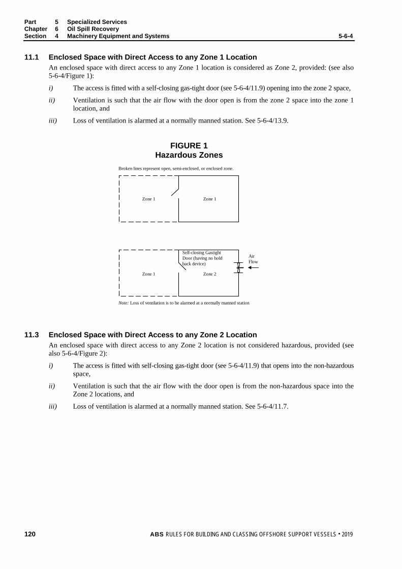
Part 5 Specialized Services Chapter 6 Oil Spill Recovery Section 4 Machinery Equipment and Systems 5-6-4
11.1 Enclosed Space with Direct Access to any Zone 1 Location An enclosed space with direct access to any Zone 1 location is considered as Zone 2, provided: (see also 5-6-4/Figure 1):
i) The access is fitted with a self-closing gas-tight door (see 5-6-4/11.9) opening into the zone 2 space,
ii) Ventilation is such that the air flow with the door open is from the zone 2 space into the zone 1 location, and
iii) Loss of ventilation is alarmed at a normally manned station. See 5-6-4/13.9.
FIGURE 1 Hazardous Zones
Broken lines represent open, semi-enclosed, or enclosed zone.
Zone 1 Zone 1
Zone 1 Zone 2
Self-closing GastightDoor (having no holdback device)
AirFlow
Note: Loss of ventilation is to be alarmed at a normally manned station
11.3 Enclosed Space with Direct Access to any Zone 2 Location An enclosed space with direct access to any Zone 2 location is not considered hazardous, provided (see also 5-6-4/Figure 2):
i) The access is fitted with self-closing gas-tight door (see 5-6-4/11.9) that opens into the non-hazardous space,
ii) Ventilation is such that the air flow with the door open is from the non-hazardous space into the Zone 2 locations, and
iii) Loss of ventilation is alarmed at a normally manned station. See 5-6-4/11.7.
120 ABS RULES FOR BUILDING AND CLASSING OFFSHORE SUPPORT VESSELS . 2019

Part 5 Specialized Services Chapter 6 Oil Spill Recovery Section 4 Machinery Equipment and Systems 5-6-4
FIGURE 2 Hazardous Zones
Broken lines represent open, semi-enclosed, or enclosed zone.
Zone 2 Zone 2
Zone 2 Non-Hazardous
Self-closing GastightDoor (having no holdback device)
AirFlow
Note: Loss of ventilation is to be alarmed at a normally manned station
11.5 Enclosed Space with Access to any Zone 1 Location (1 July 2012) An enclosed space with access to any Zone 1 location is not considered hazardous, provided the access is through either arrangement described below (see also 5-6-4/Figure 3):
11.5.1 Air Lock i) The access is fitted with two self-closing doors forming an air lock, which open toward the
nonhazardous space and has no hold-back devices,
ii) The doors are spaced apart at least a distance that prevents an individual from opening both doors simultaneously with a notice affixed to each side of each door to the effect that only one door is to be open at a time,
iii) An audible and visual alarm system to give a warning on both sides of the air lock is provided to indicate if more than one door is moved from the closed position,
iv) Ventilation is such that the non-hazardous space has ventilation overpressure greater than 25 Pa (0.25 mbar) in relation to the Zone 1 location,
v) The air lock space has independent mechanical ventilation from a gas-safe area such that, with any of the air lock doors open, the air flow is from the less hazardous space to the more hazardous space or area,
vi) The air lock space is fitted with gas detection, and
vii) Loss of ventilation overpressure between the non-hazardous space and the Zone 1 location and loss of ventilation in the air lock space are alarmed at a normally manned station. See 5-6-4/13.9.
11.5.2 Single Door i) The access is fitted with a single self-closing, gas-tight door which opens toward the
nonhazardous space and has no hold-back device,
ii) Ventilation is such that the air flow with the door open is from the non-hazardous space into the Zone 1 location with overpressure greater than 25 Pa (i.e., non-hazardous space has ventilation overpressure greater than 25 Pa (0.25 mbar) in relation to the Zone 1 location), and
iii) Loss of ventilation overpressure is alarmed at a normally manned station. See 5-6-4/13.9.
ABS RULES FOR BUILDING AND CLASSING OFFSHORE SUPPORT VESSELS . 2019 121

Part 5 Specialized Services Chapter 6 Oil Spill Recovery Section 4 Machinery Equipment and Systems 5-6-4
FIGURE 3 Hazardous Zones (1 July 2012)
Broken lines represent open, semi-enclosed, or enclosed zone.
Zone 1 Zone 1
Zone 1 Non-Hazardous
Self-closing Gastight Door (having no hold back device)
Air Flow
Note: Loss of ventilation overpressure is to be alarmed at a normally manned station. Alarms set to a minimum overpressure of 25 Pa (0.25 mbar) with respect to the adjacent Zone 1 location. See 5-6-4/13.9.
Zone 1 Non-Hazardous
Air Flow
Note: Loss of ventilation overpressure is to be alarmed at a normally manned station. Alarms set to a minimum overpressure of 25 Pa (0.25 mbar) with respect to the adjacent Zone 1 location. See 5-6-4/13.9.
Air Lock
11.7 Hold-back Devices Hold-back devices are not to be used on self-closing gas-tight doors forming hazardous area boundaries.
13 Ventilation Systems
13.1 General Ventilation systems for gas hazardous areas and safe areas are to be independent of each other. Ventilation inlets are to be located in a safe area on the open deck and as far away from gas hazardous areas as practicable. The air outlet is generally to be located in a safe area on the open deck.
13.3 Pump Room Ventilation Recovered oil pump rooms are to have a mechanical ventilating system capable of providing at least twenty air changes per hour based on the gross volume of the space. The system is to have a mechanical exhaust, natural or mechanical supply, and ducting as required to effectively purge all areas of the space. Fan motors are to be located outside the space and outside the ventilation ducts. Fans are to be of non-sparking construction in accordance with 4-8-3/11. Provision is to be made for immediate shutdown of the fan motors upon release of the fire extinguishing medium.
13.5 Ventilation of Other Hazardous Areas In general, enclosed hazardous spaces are to be provided with adequate ventilation so as to maintain them at a lower pressure than less hazardous zones. The arrangement of ventilation inlet and outlet openings in the space is to be such that the entire space is efficiently ventilated, giving special consideration to locations where gas may accumulate.
Enclosed hazardous areas (other than tanks and cofferdams) which do not contain sources for vapor leakage such as pumps, manifold, flanges or valves for recovered oil systems are to have a mechanical ventilating system capable of providing at least eight air changes per hour based on the gross volume of the space. The system is to have a mechanical exhaust, natural or mechanical supply, and ducting as required to effectively purge all areas of the space. Construction and location of fan motors are to be as required by 5-6-4/13.3.
122 ABS RULES FOR BUILDING AND CLASSING OFFSHORE SUPPORT VESSELS . 2019
Part 5 Specialized Services Chapter 6 Oil Spill Recovery Section 4 Machinery Equipment and Systems 5-6-4
13.7 Ventilation of Non-hazardous Areas Ventilation inlets and outlets for non-hazardous spaces are to be located in non-hazardous areas. Where passing through hazardous areas, ducts are to be constructed in a manner to avoid air leaks and are to have overpressure in relation to the hazardous area.
13.9 Ventilation Alarms The alarms to indicate failure of the mechanical ventilation as required by 5-6-4/11.1iii) and 5-6-4/11.3iii) are to provide audible and visual signals at the designated normally manned station. The initiation of these alarms by a fan motor running or fan rotation monitoring device is not acceptable.
The alarms to indicate loss of ventilation overpressure as required by 5-6-4/11.5.1vii) and 5-6-4/11.5.2iii) are to be set to a minimum overpressure of 25 Pa (0.25 mbar) with respect to the adjacent Zone 1 location. A differential pressure monitoring device or a flow monitoring device may be used for the initiation of the alarm. When a flow monitoring device is used and a single self-closing gas-tight door is fitted, the minimum overpressure is to be maintained with the door fully open without setting off the alarm, or alternatively, an alarm is to be given if the door is not closed. The initiation by a fan motor running or fan rotation monitoring device is not acceptable.
15 Machinery Installations in Hazardous Areas Electrical equipment and wiring in hazardous areas is to be in accordance with 5-6-4/3.11 and 4-8-4/29.
Internal combustion engines are not to be installed in Zone 0 hazardous areas. When essential for operational purposes, internal combustion engines may be installed in Zone 1 and 2 hazardous areas. Such installations will be subject to special consideration. Fired boilers are not to be installed in hazardous areas.
Exhaust outlets of internal combustion engines and boilers are to discharge outside of all hazardous areas. Air intakes are to be located not less than 3 m (10 ft) from hazardous areas. Exhaust outlets of internal combustion engines are to be fitted with suitable spark-arresting devices, and exhaust piping insulation is to be protected against possible oil absorption in areas or spaces where the exhausting piping is exposed to oil or oil vapors.
The outlets of vent pipes from internal-combustion engine crankcases are to discharge outside of all hazardous areas.
17 Fire Extinguishing Systems and Equipment
17.1 Deck Area The following fire fighting equipment is to be provided for protection of the operating deck area.
17.1.1 Fire Extinguishers Two dry powder fire extinguishers, each with a capacity of at least 50 kg (110 lb), are to be provided. The fire extinguishers are to be located in the vicinity of the deck area where the equipment for handling of recovered oil is located and are to be fitted with hoses of adequate length to reach the oil handling equipment.
17.1.2 Portable Foam Applicator Units Two portable foam applicator units are to be provided. A portable foam applicator unit is to consist of an air-foam nozzle of an inductor type capable of being connected to the fire main by a fire hose together with a portable tank containing at least 20 liters (5 U.S. gallons) of foam-making liquid. The nozzle is to be capable of producing effective foam suitable for extinguishing an oil fire, at the rate of at least 90 m3/hr (3180 ft3/hr). A total of at least eight portable tanks of foam-making liquid are to be supplied on board. In instances where, due to the size of the vessel, only one fire hydrant is required to be fitted, the vessel need only be provided with one portable foam applicator unit.
ABS RULES FOR BUILDING AND CLASSING OFFSHORE SUPPORT VESSELS . 2019 123
Part 5 Specialized Services Chapter 6 Oil Spill Recovery Section 4 Machinery Equipment and Systems 5-6-4
17.3 Pump Rooms Recovered oil pump rooms are to be provided with an approved fixed fire extinguishing system controlled from a readily accessible position outside the pump room. See also 5-6-4/13.3.
17.5 Gas Measuring Instruments • Two portable instruments of an approved type are to be provided onboard the vessel for hydrocarbon
gas detection/measurements.
• Two portable hydrogen sulfide gas monitoring devices are to be provided onboard the vessel.
19 Oil Pollution Prevention Measures (1 July 2012) Pollution prevention equipment such as oil discharge monitoring and control systems to process oil contaminated water from machinery space bilges are to be appropriate to the vessel when engaged in operations other than oil recovery. This is to be in accordance with 4-6-4/5.7.
During oil recovery operations, the oil content of any processed, recovered oil/water mixture discharged overboard is to comply with the requirements of the Administration having oversight of the spill response.
21 Other Requirements
21.1 Low sea suctions are to be provided for the sea water cooling pumps for the machinery and all fire pumps.
21.3 If installed, heating coils in recovered oil tanks and adjacent tanks are to be provided with means for blanking off. If applicable, the observation tanks for steam heating return lines from recovered oil tanks are to be located as far away from any sources of ignition as possible and adequately ventilated.
124 ABS RULES FOR BUILDING AND CLASSING OFFSHORE SUPPORT VESSELS . 2019

P A R T S e c t i o n 5 : O i l S p i l l R e c o v e r y – C a p a b i l i t y C l a s s 1
5 C H A P T E R 6 Oil Spill Recovery
S E C T I O N 5 Oil Spill Recovery – Capability Class 1
1 General (1 July 2012) Offshore support vessels that comply with this Section of these Rules and have been designed for oil recovery operations, but the oil recovery equipment has not been installed on board, are eligible for the class notation À A1 Offshore Support Vessel (OSR-C1). The requirements of Sections 5-6-1 to 5-6-4 apply except as modified below.
3 Oil Spill Recovery – Capability
3.1 General i) The area in which the oil recovery equipment will be installed and the tanks to be used for
recovered oil are to be defined and marked on the general arrangement plan of the vessel.
ii) Hazardous areas are to be delineated in accordance with 5-6-4/9 based on i) above.
3.3 Operating Manual The operating manual is to reflect the expected list of oil recovery equipment to be used, its location and its deployment and stowage procedures.
3.5 Hull Construction (1 July 2012) 3.5.1 Recovered Oil Storage Tanks
Tanks primarily used for purposes other than oil recovery (e.g., ballast, fuel oil and fresh water tanks), excluding forepeak tanks, may be used for the storage of recovered oil during oil recovery operations.
3.5.2 Recovered Oil Storage Tank Openings Suitable openings to facilitate tank cleaning and gas freeing of the recovered oil storage tanks are to be provided. These openings, together with any openings for the deployment of portable pumps and hoses, are to be located on the open deck.
3.7 Machinery Equipment and Systems i) Use of movable (non-fixed) pipe sections and flexible hoses is permitted in the recovered oil
piping system.
ii) Oil recovery equipment and independent power-packages may be stored ashore ready to be installed for use.
ABS RULES FOR BUILDING AND CLASSING OFFSHORE SUPPORT VESSELS . 2019 125
P A R T S e c t i o n 6 : O i l S p i l l R e c o v e r y – S t a n d b y C l a s s 2
5 C H A P T E R 6 Oil Spill Recovery
S E C T I O N 6 Oil Spill Recovery – Standby Class 2 (1 July 2012)
1 General Offshore support vessels that comply with this Section of the Rules and have been designed for the recovery of oil having a flash point, at the time of recovery, exceeding 60°C (140°F) are eligible for the class notation À A1 Offshore Support Vessel (OSR-S2). The requirements of Sections 5-6-1 to 5-6-4 apply except as modified below.
3 Plans and Operating Manual In 5-6-1/5 and 5-6-1/7, provisions dealing with hazardous areas are not applicable.
The operating manual of 5-6-1/7 is to provide information regarding procedures to monitor and record the flash point of the recovered oil. The procedures are to include guidelines specifying conditions when to withdraw the vessel from oil recovery operations should the flash point of the recovered oil not exceed 60°C (10°F).
5 Hull Construction
5.1 Separation of Recovered Oil Tanks In lieu of 5-6-3/3.1.2, the vessel is to comply with:
i) Tanks forward of the collision bulkhead are not to be arranged for the carriage of recovered oil.
ii) As far as practicable, recovered oil tanks are to be located away from the machinery spaces of category A. However, where it is found necessary to locate the recovered oil tanks adjacent to or inside the machinery spaces of category A, the arrangements are to reduce the area of the tank boundary common with the machinery space of category A to a minimum and comply with the following:
a) Recovered oil tanks having boundaries common with machinery spaces of category A are not to contain oils having flash point of 60°C (140°F) or less.
b) At least one of their vertical sides is to be contiguous to the machinery space boundary.
c) The bottom of the recovered oil tank is not to be so exposed that it will be in direct contact with flame should there be a fire in a Category A machinery space. The recovered oil tank is to extend to the double bottom. Alternatively, the bottom of the recovered oil tank is to be fitted with a cofferdam. The cofferdam is to be fitted with suitable drainage arrangements to prevent accumulation of oil in the event of oil leakage from the tank.
d) Recovered oil tanks are to be located such that no spillage or leakage therefrom can constitute a hazard by falling on heated surfaces or electrical equipment. If this is not practicable, the latter are to be protected from such spillage or leakage by shields, coamings or trays as appropriate.
126 ABS RULES FOR BUILDING AND CLASSING OFFSHORE SUPPORT VESSELS . 2019

Part 5 Specialized Vessels and Services Chapter 6 Oil Spill Recovery Section 6 Oil Spill Recovery – Standby Class 2 5-6-6
5.3 Penetration of Recovered Oil Tanks In lieu of 5-6-3/3.5, the vessel is to comply with:
i) Electrical cables are not to pass through recovered oil tanks unless enclosed within an oil tight trunk or equivalent.
ii) Pipes passing through recovered oil tanks are to be of steel except that other materials may be considered where it is demonstrated that the material is suitable for the intended service.
5.5 Structural Fire Protection The provisions of 5-6-3/5 are not applicable.
7 Machinery Equipment and Systems
7.1 Machinery and Equipment Installation For 5-6-4/3, the provisions of 5-6-4/3.1, 5-6-4/3.7, 5-6-4/3.9.1, and 5-6-4/3.15 are applicable. For piping or cables which pass through tanks for recovered oil, refer to 5-6-6/5.3.
7.3 Recovered Oil Piping Systems (2014) Recovered oil piping systems are to be in accordance with 5-6-4/5 except compliance with 5-6-4/5.3, 5-6-4/5.9, and 5-6-4/5.15 is not required. Recovered oil piping systems passing through machinery spaces are to be in accordance with the requirements for fuel oil transfer systems. See 4-6-4/13.
7.5 Recovered Oil Tank Venting Systems A tank venting system complying with 5-6-4/7 is to be provided for recovered oil storage tanks. Alternatively, a venting system consisting of individual return-bend vents with corrosion resistant flame screens may be provided. Refer to 4-6-4/9. Provisions of 5-6-4/7.9 and 5-6-4/7.11 are applicable for a venting system consisting of individual return-bend vents.
7.7 Hazardous Areas The provisions of 5-6-4/9 and 5-6-4/11 are not applicable.
7.9 Ventilation Systems In lieu of 5-6-4/13, recovered oil pump rooms are to have a mechanical ventilating system capable of providing at least eight air changes per hour based on the gross volume of the space. The system is to have a mechanical exhaust, natural or mechanical supply, and ducting as required to effectively purge all areas of the space.
7.11 Machinery Installations in Hazardous Areas The provisions of 5-6-4/15 are not applicable.
7.13 Fire Extinguishing Systems and Equipment For 5-6-4/17, the provisions of 5-6-4/17.1 and 5-6-4/17.5 are applicable. The provisions of 5-6-4/17.3 are not applicable.
ABS RULES FOR BUILDING AND CLASSING OFFSHORE SUPPORT VESSELS . 2019 127

P A R T S e c t i o n 7 : O i l S p i l l R e c o v e r y – C a p a b i l i t y C l a s s 2
5 C H A P T E R 6 Oil Spill Recovery
S E C T I O N 7 Oil Spill Recovery – Capability Class 2 (1 July 2012)
1 General Offshore support vessels that comply with this Section of the Rules and have been designed for the recovery of oil having a flash point, at the time of recovery, exceeding 60°C (140°F) but the oil recovery equipment has not been installed on board, are eligible for the class notation À A1 Offshore Support Vessel (OSR-C2). The requirements of Sections 5-6-1 to 5-6-4 apply except as modified below.
3 Plans and Operating Manual In 5-6-1/5 and 5-6-1/7, provisions dealing with hazardous areas are not applicable.
In addition to the provisions of 5-6-1/5, the area in which the oil recovery equipment will be installed and the tanks to be used for recovered oil are to be defined and marked on the general arrangement plan of the vessel.
The operating manual of 5-6-1/7 is to provide information regarding procedures to monitor and record the flash point of the recovered oil. The procedures are to include guidelines specifying conditions when to withdraw the vessel from oil recovery operations should the flash point of the recovered oil not exceed 60°C (10°F).
The operating manual of 5-6-1/7 is to reflect the expected list of oil recovery equipment to be used, its location and its deployment and stowage procedures.
5 Hull Construction
5.1 Recovered Oil Storage Tanks Tanks primarily used for purposes other than oil recovery (e.g., ballast, fuel oil and fresh water tanks), excluding forepeak tanks, may be used for the storage of recovered oil during oil recovery operations.
5.3 Separation of Recovered Oil Tanks In lieu of 5-6-3/3.1.2, the vessel is to comply with:
i) Tanks forward of the collision bulkhead are not to be arranged for the carriage of recovered oil.
ii) As far as practicable, recovered oil tanks are to be located away from the machinery spaces of category A. However, where it is found necessary to locate the recovered oil tanks adjacent to or inside the machinery spaces of category A, the arrangements are to reduce the area of the tank boundary common with the machinery space of category A to a minimum and comply with the following:
a) Recovered oil tanks having boundaries common with machinery spaces of category A are not to contain oils having flash point of 60°C (140°F) or less.
b) At least one of their vertical sides is to be contiguous to the machinery space boundary.
128 ABS RULES FOR BUILDING AND CLASSING OFFSHORE SUPPORT VESSELS . 2019
Part 5 Specialized Vessels and Services Chapter 6 Oil Spill Recovery Section 7 Oil Spill Recovery – Capability Class 2 5-6-7
c) The bottom of the recovered oil tank is not to be so exposed that it will be in direct contact with flame should there be a fire in a Category A machinery space. The recovered oil tank is to extend to the double bottom. Alternatively, the bottom of the recovered oil tank is to be fitted with a cofferdam. The cofferdam is to be fitted with suitable drainage arrangements to prevent accumulation of oil in the event of oil leakage from the tank.
d) Recovered oil tanks are to be located such that no spillage or leakage therefrom can constitute a hazard by falling on heated surfaces or electrical equipment. If this is not practicable, the latter are to be protected from such spillage or leakage by shields, coamings or trays as appropriate.
5.5 Location of Recovered Oil Tank Openings Where 5-6-7/5.1 applies, suitable openings to facilitate tank cleaning and gas freeing of the recovered oil storage tanks are to be provided. These openings, together with any openings for the deployment of portable pumps and hoses, are to be located on the open deck.
5.7 Penetration of Recovered Oil Tanks In lieu of 5-6-3/3.5, the vessel is to comply with:
i) Electrical cables are not to pass through recovered oil tanks unless enclosed within an oil tight trunk or equivalent.
ii) Pipes passing through recovered oil tanks are to be of steel except that other materials may be considered where it is demonstrated that the material is suitable for the intended service.
5.9 Structural Fire Protection The provisions of 5-6-3/5 are not applicable.
7 Machinery Equipment and Systems
7.1 Machinery and Equipment Installation Oil recovery equipment and independent power-packages may be stored ashore ready to be installed for use.
For 5-6-4/3, the provisions of 5-6-4/3.1, 5-6-4/3.7, 5-6-4/3.9.1, and 5-6-4/3.15 are applicable. For piping or cables which pass through tanks for recovered oil, refer to 5-6-7/5.7.
7.3 Recovered Oil Piping Systems (2014) Recovered oil piping systems are to be in accordance with 5-6-4/5 except compliance with 5-6-4/5.3, 5-6-4/5.9, and 5-6-4/5.15 is not required. Recovered oil piping systems passing through machinery spaces are to be in accordance with the requirements for fuel oil transfer systems. See 4-6-4/13.
Use of movable (non-fixed) pipe sections and flexible hoses is permitted in the recovered oil piping system.
7.5 Recovered Oil Tank Venting Systems A tank venting system complying with 5-6-4/7 is to be provided for recovered oil storage tanks. Alternatively, a venting system consisting of individual return-bend vents with corrosion resistant flame screens may be provided. Refer to 4-6-4/9. Provisions of 5-6-4/7.9 and 5-6-4/7.11 are applicable for a venting system consisting of individual return-bend vents.
7.7 Hazardous Areas The provisions of 5-6-4/9 and 5-6-4/11 are not applicable.
ABS RULES FOR BUILDING AND CLASSING OFFSHORE SUPPORT VESSELS . 2019 129
Part 5 Specialized Vessels and Services Chapter 6 Oil Spill Recovery Section 7 Oil Spill Recovery – Capability Class 2 5-6-7
7.9 Ventilation Systems In lieu of 5-6-4/13, recovered oil pump rooms are to have a mechanical ventilating system capable of providing at least eight air changes per hour based on the gross volume of the space. The system is to have a mechanical exhaust, natural or mechanical supply, and ducting as required to effectively purge all areas of the space.
7.11 Machinery Installations in Hazardous Areas The provisions of 5-6-4/15 are not applicable.
7.13 Fire Extinguishing Systems and Equipment For 5-6-4/17, the provisions of 5-6-4/17.1 and 5-6-4/17.5 are applicable. The provisions of 5-6-4/17.3 are not applicable.
130 ABS RULES FOR BUILDING AND CLASSING OFFSHORE SUPPORT VESSELS . 2019
P A R T C h a p t e r 7 : S a f e t y S t a n d b y R e s c u e
5 C H A P T E R 7 Safety Standby Rescue
CONTENTS SECTION 1 General .................................................................................................. 133
1 Application ...................................................................................... 133 3 Classification ................................................................................... 133
3.1 Vessels with Safety Standby Rescue Capability ......................... 133 5 Submission of Plans ....................................................................... 135
SECTION 2 Definitions ............................................................................................. 136
1 Safety Standby Service ................................................................... 136 3 Survivor ........................................................................................... 136
SECTION 3 General Requirements ......................................................................... 137
1 Speed and Maneuverability ............................................................ 137 3 Navigation Bridge ............................................................................ 137
3.1 Visibility ....................................................................................... 137 3.3 Structure ...................................................................................... 137 3.5 Windows ...................................................................................... 137
5 Other Deckhouses .......................................................................... 138 7 Rescue Zone ................................................................................... 138 9 Recovery from the Sea ................................................................... 138 11 Load Line ........................................................................................ 138
SECTION 4 Accommodations for Survivors ......................................................... 139
1 Required Space Allotments ............................................................ 139 1.1 General Requirements ................................................................ 139 1.3 Seating ........................................................................................ 139 1.5 Sanitary Facilities ........................................................................ 139
3 Casualty Area ................................................................................. 139 3.1 Decontamination Area ................................................................. 140 3.3 Reception Area ............................................................................ 140 3.5 Treatment Area ........................................................................... 140 3.7 Recovery Area ............................................................................. 140 3.9 Sanitary Area ............................................................................... 140 3.11 Morgue ........................................................................................ 141
ABS RULES FOR BUILDING AND CLASSING OFFSHORE SUPPORT VESSELS . 2019 131
SECTION 5 Rescue and Safety Equipment ............................................................ 142 1 Rescue Boats .................................................................................. 142 3 Rescue Nets .................................................................................... 142 5 Searchlights .................................................................................... 142 7 Water Spraying System .................................................................. 142 9 Gas Detection ................................................................................. 143 11 Person Overboard Alarm ................................................................ 143 13 Deck Lighting .................................................................................. 143 15 Helicopter Winching ........................................................................ 143 17 Towing ............................................................................................. 143 19 Medical Stores ................................................................................ 143 21 Miscellaneous ................................................................................. 144
SECTION 6 Navigation and Communication Equipment ..................................... 145
1 Navigational Equipment .................................................................. 145 3 Radio and Communication Equipment ........................................... 145
SECTION 7 Surveys .................................................................................................. 146
132 ABS RULES FOR BUILDING AND CLASSING OFFSHORE SUPPORT VESSELS . 2019

P A R T S e c t i o n 1 : G e n e r a l
5 C H A P T E R 7 Safety Standby Rescue
S E C T I O N 1 General
1 Application The requirements in this Chapter apply to Offshore Support Vessels designed to carry out rescue and standby services for offshore installations.
3 Classification In accordance with Section 1-1-2 of the OSV Rules Supplement to the ABS Rules for Conditions of Classification (Part 1) and 5-1-1/5.1 of these Rules, the classification À A1 Offshore Support Vessel (SSR) is to be assigned to vessels which have been built in accordance with these requirements and other relevant sections of these Rules for safety standby service at the assigned freeboards. In addition an entry will be made in the Record, indicating the class designation together with the number of survivors the vessel has been certified to accommodate [e.g., GR A – (320), GR B – (250), GR C – (15), etc.].
3.1 Vessels with Safety Standby Rescue Capability (1 July 2017) Vessels not in full compliance with these Rules or not specifically built for the service intended to be covered by these Rules, but which have some safety standby rescue capability in addition to their regular service, may be considered and reviewed under the intent of these Rules, in relation to the specific safety standby rescue requirements.
This notation is optional and it is the responsibility of the Owner to select the notation suitable for the intended service and ensure that the vessel is operated in a safe environment with respect to the SSR operation.
As a minimum, such vessels are to meet the following requirements:
• 5-7-1/5, 5-7-3/7, 5-7-3/11, 5-7-4/1.1, 5-7-5/3, 5-7-5/5, 5-7-5/17 and Section 5-7-7
• 5-7-3/1, 5-7-3/3, 5-7-4/1.3, 5-7-4/1.5, 5-7-4/3, 5-7-5/1, 5-7-5/11, 5-7-5/13, 5-7-5/15, 5-7-5/19, 5-7-5/21, 5-7-6/1 and 5-7-6/3 except as amended in the table below
Such vessels complying with these requirements may be distinguished in the Record by the notation SSR Capable (number of survivors, operational area) inserted after the appropriate vessel class notations. For example:
i) À A1 SSR Capable (50, Coastwise less than 50NM), or
ii) À A1 Offshore Support Vessel, SSR Capable (50, Coastwise less than 50NM), or
iii) À A1 Offshore Support Vessel, SSR Capable (30, Coastwise less than 30NM)
ABS RULES FOR BUILDING AND CLASSING OFFSHORE SUPPORT VESSELS . 2019 133

Part 5 Specialized Services Chapter 7 Safety Standby Rescue Section 1 General 5-7-1
5-7-3/1 Speed and Maneuverability 5-7-3/1 i), ii), or iii). In addition, control of the propulsion machinery and station keeping system by one person on the navigation bridge is to be possible.
5-7-3/3 Navigation Bridge The navigation bridge is to extend across the breadth of the vessel as far as practicable, and is to be so located and arranged so that there is an unobstructed view all around (as far as the required size of the mullions permits). In addition, a clear view of the area at the side of where rescue operations will be carried out is to be provided unless means of direct communication to the bridge are provided.
5-7-4/1.3 Seating Sufficient number of seats, including those in the reception areas and crew accommodations, are to be available for the survivors. The number of seats indicated in the table in 5-7-4/1.3 may be used as guidance.
5-7-4/1.5 Sanitary Facilities Sanitary facilities are to be available exclusively for the survivors. At least one installation compromising a toilet, a wash basin and a shower is to be provided per group of 50 survivors. There should be a minimum 0.8 tonnes of fresh water and a minimum 0.65 tonnes of potable water tank capacities per group of 50 survivors.
5-7-4/3 Casualty Area A designated space is to be provided to accommodate survivors meeting general requirements in 5-7-4/1.1. Facilities for shelving and securement are to be provided to store the number of bodies in a cool ventilated space considering the number of survivors. Minimum 4 bodies to be considered for the space. This space is to be screened from survivors.
5-7-5/1 Rescue Boat The vessel is to be equipped with at least one SOLAS approved rescue boat. Consideration may be given based on the size of vessel and intended operational area.
5-7-5/11 Person overboard alarm An efficient whistle and an efficient bell which is clearly audible throughout the vessel is to be provided for person overboard.
5-7-5/13 Deck Lighting Sufficient lighting is to be provided along the rescue areas. 5-7-5/15 Helicopter Winching All safety standby vessels are to be provided with a well-lighted, unobstructed deck
space for helicopter winching. Consideration may be given based on the intended operation (maximum distance from shore, duration of service and the number of survivors).
5-7-5/19 Medical Stores The medical stores are to be provided in accordance with local regulations. The requirements in 5-7-5/19 can be taken as a guidance with due consideration of the operational area and size of the vessel. As a minimum, the vessel is to be provided with blankets, towels and disposable coveralls in sufficient quantity for the number of survivors for which the vessel intends to carry.
5-7-5/21 Miscellaneous The vessel is to be provided with safety equipment in 5-7-5/21 as far as practicable. For vessels of less than 500 GRT or operating within a limited area, the min number of the safety equipment in the list may be specially considered based on National Standard. Life jackets to be provided for children when the rescue area has children in water.
5-7-6/1 Navigational Equipment All safety standby vessels, regardless of size, are to be provided with shipborne navigational equipment as required for new vessels by Regulation 19 of Chapter V of SOLAS 74, as amended for vessels of 500 gross tonnage and upwards, as well as the radio direction-finding equipment and radio homing equipment specified in paragraphs (p) and (q) of the regulation. For vessels of less than 500 GRT or vessels operating in limited area, the navigational equipment may be specially considered provided the same is approved by the National Administration.
5-7-6/3 Radio and communication equipment
Vessels classed for Safety Standby Service are to be provided with radio equipment in accordance with 5-7-6/3. For vessels of less than 500 GRT or vessels operating in limited area, the navigational equipment may be specially considered provided the same is approved by the National Administration.
Additional requirements may be imposed by the flag and/or coastal State Administrations with whom the vessel is registered or by the Administration within whose territorial jurisdiction the vessel is intended to operate.
134 ABS RULES FOR BUILDING AND CLASSING OFFSHORE SUPPORT VESSELS . 2019
Part 5 Specialized Services Chapter 7 Safety Standby Rescue Section 1 General 5-7-1
5 Submission of Plans In addition to the plans required to be submitted by Section 1-1-4 of the OSV Rules Supplement to the ABS Rules for Conditions of Classification (Part 1), the following plans are to be submitted in the same manner:
• An operating booklet is to be provided and sighted by the Surveyor onboard the vessel. It is to include information on the use of safety and rescue equipment and procedures to be followed to evacuate persons from an offshore structure, from another vessel or for rescue from the sea, as well as information on the arrangements and use of the vessel’s radio communication equipment required by these Rules.
• General arrangement (including accommodations for survivors)
• Rescue and safety, equipment
The following drawings are to be submitted for reference:
• Lines and offsets
• Curves of form, or equivalent
• Cross curves of stability
• Capacity plan, giving centers of gravity and tank free surface corrections
ABS RULES FOR BUILDING AND CLASSING OFFSHORE SUPPORT VESSELS . 2019 135

P A R T S e c t i o n 2 : D e f i n i t i o n s
5 C H A P T E R 7 Safety Standby Rescue
S E C T I O N 2 Definitions
1 Safety Standby Service A vessel classed for Safety Standby Service is an unrestricted service vessel which has been adapted and has special features for the evacuation and reception of personnel from an offshore installation and the rescue and care of persons from another vessel or from the sea. Vessels which have been designed and constructed for other purposes, such as offshore supply, fire fighting, diving support, etc. may be classed for safety standby service, provided the requirements of these Rules are complied with.
Depending on the number of survivors the vessel is capable of accommodating, safety standby vessels are categorized in three groups, as indicated in the following table:
Category Number of Survivors, N (see Note 1)
Lf in meters (feet) Class Designation in the Record (see Note 2)
Group A N > 300 ≥ 35 (115) GR A – (N) Group B 300 ≥ N ≥ 20 ≥ 35 (115) GR B – (N) Group C N < 20 ≥ 30 (98.5) GR C – (N)
Notes: 1 Possible accommodation for the onboard installation.
2 The class notation together with the number of survivors, (N), in parenthesis will be entered in the Record.
3 Survivor A person evacuated from an offshore installation or from another vessel on account of an emergency or rescued from the sea.
136 ABS RULES FOR BUILDING AND CLASSING OFFSHORE SUPPORT VESSELS . 2019

P A R T S e c t i o n 3 : G e n e r a l R e q u i r e m e n t s
5 C H A P T E R 7 Safety Standby Rescue
S E C T I O N 3 General Requirements
1 Speed and Maneuverability
The vessel is to be capable of developing a trial speed of not less than 10 knots in calm weather and is to be equipped with one of the following:
i) A 360-degree azimuthing thruster unit and either single screw propulsion with reversing gearbox or controllable pitch propeller. The thruster unit is to be capable of developing an ahead speed of 4 knots and is not to be dependent on the main engine for its source of power.
ii) Twin screw propulsion and forward side thruster unit arrangement such that the vessel is capable of developing 4 knots in the ahead direction, in calm weather, with one main propulsion unit out of action.
iii) Equivalent main and maneuvering propulsion systems providing similar level of redundancy and maneuvering capabilities.
iv) Control of the propulsion machinery and station keeping system by one person on the navigation bridge is to be possible.
3 Navigation Bridge
3.1 Visibility The navigation bridge is to extend across the breadth of the vessel and is to be so located and arranged so that there is an unobstructed view all around, as far as the required size of the mullions permits, and in particular a clear view of the area where rescue operations will be carried out.
In general the navigation bridge is to be not lower than the second tier above the forecastle deck.
3.3 Structure The stiffening is to be arranged so that mullion stiffeners are continuous between decks, with horizontal stiffeners intercostal between the mullion stiffeners. The front, end and side stiffeners are to be in alignment with the stiffeners of the deckhouse below.
The stiffeners and plating are to be in accordance with Section 3-2-11. As the second tier above the forecastle deck, h for front stiffeners is not taken less than 2.5 m and for side stiffeners is not less than 1.70 m. The ratio of tween deck height to mullion stiffener depth is to not exceed 18 for front mullions and 30 for side mullions.
Flat bars are not to be used for mullion stiffeners, where used elsewhere, flat bars are to have a depth to thickness not greater than 10.
3.5 Windows Windows are to be in accordance with International or National marine standards in which the design pressures are given in terms of the windows longitudinal location and height above the design waterline.
The thickness of the toughened safety glass is to be determined from the equations in the standard based on design pressure and size of window. Windows are to be fitted from the outside.
ABS RULES FOR BUILDING AND CLASSING OFFSHORE SUPPORT VESSELS . 2019 137

Part 5 Specialized Services Chapter 7 Safety Standby Rescue Section 3 General Requirements 5-7-3
Bridge front windows and those of the forward end of the bridge sides are to be provided with efficient means of being blanked off, internally or externally.
Portable storm shutters may be used for this purpose, provided they are stowed in an accessible position, so as to be readily mounted and secured. Sufficient storm shutters are to be carried to cover any three bridge front and side windows. Storm shutters are to be of strength equivalent to the bulkhead and are to provide at least limited visibility from the bridge.
Polarized or tinted windows are not to be fitted. See also 3-2-17/9.
5 Other Deckhouses (2015) Other deckhouses are to be in accordance with Section 3-2-11. Portlights and windows are to be in accordance with Sections 3-2-7, 3-2-9, and 3-2-17.
7 Rescue Zone (2015) A rescue zone with a length of not less than 5 m (16.4 ft) is to be established and extended as far as possible on each side of the vessel. This zone is to be located well clear of the propellers and as close to midships as practicable, with a clear deck area port to starboard to permit the boarding of survivors and to carry on rescue operations. Bulwarks or railings in the rescue zone are to be provided with gates or chains which are readily openable or removable.
Cargo rails with height 1.83 m (6.0 ft) and less are to be openable or removable type. Where cargo rails are more than 1.83 m (6.0 ft) high, they are to be permanently attached and have sufficient openings of at least 9.14 m2 (98.4 ft2) in close proximity to rescue zone (not more than 1 m on either side of zone) to perform rescue operations.
Arrangements are to be provided for deploying boarding nets and for attachment of lifelines. In general, the rescue zone is to be free of hull fittings and projections and overboard discharges which would impede rescue operations. Electric lights in watertight fixtures are to be provided to illuminate the rescue zones and reception areas. Rescue zones are to be marked so as to be readily identified from seaward.
9 Recovery from the Sea Every safety standby service vessel is to be provided with a system to aid access up the vessel’s side from the sea or from a rescue boat alongside. This system is to provide a more rigid non-slip climbing and grip surface than is provided by traditional rope scramble nets and is to be constructed from materials that are resistant to the marine environment. The system is to be designed to avoid injury to survivors and is to be secured to the vessel in such away that it will hang clear of the vessel’s side by at least 0.25 m (10 in.) when deployed. In addition, every safety standby vessel is to be provided with at least one power assisted method of recovering injured persons from the sea.
11 Load Line A vessel to be classed for safety standby service is to have a load line certificate, and the loading condition of the vessel on safety standby service is to be such that the highest freeboard mark would not be submerged if the number of survivors for which vessel is certified would be taken aboard. Weight of survivors is to be taken as 75 kg (165 lb) each.
The freeboard in the rescue zone area is not to exceed 1.75 m (5.74 ft). A higher freeboard may be approved for exposed locations if the ability to recover persons from the sea can be proved.
138 ABS RULES FOR BUILDING AND CLASSING OFFSHORE SUPPORT VESSELS . 2019

P A R T S e c t i o n 4 : A c c o m m o d a t i o n s f o r S u r v i v o r s
5 C H A P T E R 7 Safety Standby Rescue
S E C T I O N 4 Accommodations for Survivors
1 Required Space Allotments
1.1 General Requirements Spaces provided for shelter of the survivors are to be enclosed from the weather and provided with heat, light and ventilation. In an emergency, survivors may be lodged in crew accommodations, except for sanitary areas, galleys, berths for the master and two crew members, the radio room, the wheelhouse and main access passage ways which are to be clear.
The General Arrangement drawing required by 5-7-1/5 is to contain dimensioned spaces for those individual seating areas required in this Section.
1.3 Seating Seats of the number specified in the table below, including those in the reception areas and crew accommodations, are to be available for the survivors.
Category Number of Seats
Group A 66 Group B 50 Group C 20
1.5 Sanitary Facilities Wash basins, showers and toilets, which may include those provided for the crew, are to be not less than the following:
Category Wash Hand Basins
Showers WCs (of which 3 may
be chemical)
Fresh Water Tank Capacity
(tonnes)
Potable Water Tank Capacity
(tonnes) Group A 13 13 13 6 6 Group B 10 10 10 5 4 Group C 4 4 4 2 2
For the survivors’ consumption, the vessel is to be provided with a fresh water tank and a potable water tank of the capacities specified in the above table.
3 Casualty Area The casualty area is to be external to the crew accommodation and is to provide ready access from the survivor rescue area. Transfer of survivors to the helicopter winching area is to be considered, and easy-unobstructed access is to be arranged. The Treatment Room, Reception Area and at least 12 of the Recovery Area berths (including the 2 singles) are to be located on the same deck as the Rescue zones unless special arrangements for casualty transfer are approved by the Administration.
ABS RULES FOR BUILDING AND CLASSING OFFSHORE SUPPORT VESSELS . 2019 139

Part 5 Specialized Services Chapter 7 Safety Standby Rescue Section 4 Accommodations for Survivors 5-7-4
The casualty area is to consist of the following areas designed to allow the easy flow of survivors. The spaces are to be clearly marked for ease of distribution of survivors and are to be consisted of:
• Decontamination Area
• Reception Area
• Treatment Area
• Recovery Area
• Sanitary Area
3.1 Decontamination Area Decontamination Area, which may only be partially enclosed is to be equipped with a shower system suitable for overall cleaning of survivors and crew members before they proceed into reception facilities.
3.3 Reception Area Reception Area is to be a well lit, heated and ventilated space with 5 seats for survivors.
3.5 Treatment Area Treatment Area is to be provided with a deck area of 15 m2 (161.4 ft2) with deck scuppers and access and exits for easy transportation of stretchers. The space is to be well lit, heated and ventilated.
3.7 Recovery Area Recovery Area is to be separated from, but near to the treatment area for monitoring the injured and is to be provided with a well lit, heated and ventilated space to accommodate survivors’ berths of the number given in the table below. All survivors’ berths are to be accessible by stretcher.
Category Survivors’ Berths Single Tier Berths (see Note 1)
Group A 26 2 Group B 20 2 Group C 10 2
Note: 1 The number of single tier berths is included in the total number
of survivors’ berths, not in addition to that number.
3.9 Sanitary Area Showers, WCs and wash hand basins are to be provided in the treatment/recovery area, as specified in the table below. These are to be included in the total indicated above under “Sanitary Facilities”.
Category Wash Hand Basins
Showers WCs (of which 3 may
be chemical) Group A 5 5 5 Group B 4 4 4 Group C 2 2 2
140 ABS RULES FOR BUILDING AND CLASSING OFFSHORE SUPPORT VESSELS . 2019

Part 5 Specialized Services Chapter 7 Safety Standby Rescue Section 4 Accommodations for Survivors 5-7-4
3.11 Morgue Facilities for shelving and securement are to be provided to store the number of bodies specified in the table below in a cool ventilated space. This space is to be screened from survivors.
Category Number of Bodies
Group A 13 Group B 10 Group C 4
ABS RULES FOR BUILDING AND CLASSING OFFSHORE SUPPORT VESSELS . 2019 141

P A R T S e c t i o n 5 : R e s c u e a n d S a f e t y E q u i p m e n t
5 C H A P T E R 7 Safety Standby Rescue
S E C T I O N 5 Rescue and Safety Equipment
1 Rescue Boats (2014) A sufficient number of power-driven rescue boats having the following capacity are to be provided and kept ready for immediate use.
Category Minimum Number of Rescue Boats
Total Capacity of Rescue Boat
Number of Crew
Group A 1 15 persons/boat 3/boat Group B 1 15 persons/boat 3/boat Group C 1 15 persons/boat 3/boat
For Group C vessel, capacity and number of crew for an additional rescue boat, if fitted, may be 9 persons/boat and 2/boat.
Rescue boats, which may be of rigid or inflated construction or a combination of both, and launching arrangements, are to meet the requirements of Chapters V and VI of the International Life-Saving Appliance (LSA) Code (as applicable) Resolution MSC.48(66) or equivalent.
Rescue boats are to be capable of maneuvering, for at least 4 hours, at a speed of at least 20 knots in calm water.
Should the rescue boat davits depend upon an electrical source for their operation, an emergency source of electrical power is to be available and sufficient to supply at least one rescue boat davit for a period of at least 4 hours of normal operations. For emergency source of power, see 4-8-2/5.
3 Rescue Nets A rescue net is to be provided at each rescue zone. Nets are to be not less than 5 m (16.25 ft) wide, weighted at the bottom and long enough to extend at least 1 m (3.25 ft) below the waterline with the vessel at light draft.
5 Searchlights The safety standby vessel is to have at least two searchlights capable of 50 lux at 250 meters (820 ft) with 360 degrees rotation adjustable from inside the navigation bridge.
7 Water Spraying System A water spray system is to be installed to protect from heat and fire those engaged in rescue operations on exposed deck areas, the boundaries of the external safety standby area. The system is to be capable of covering all areas mentioned above with a uniformly distributed water spray of at least 5 liters/minute/square meter area.
142 ABS RULES FOR BUILDING AND CLASSING OFFSHORE SUPPORT VESSELS . 2019

Part 5 Specialized Services Chapter 7 Safety Standby Rescue Section 5 Rescue and Safety Equipment 5-7-5
9 Gas Detection Effective gas detection equipment, which does not rely on continuous manual operation, is to be provided together with instructions for use and testing. Such equipment may be portable and/or fixed.
11 Person Overboard Alarm A bridge operated “person overboard” general alarm is to be installed which is clearly audible throughout the vessel and is separated and distinct from all other alarms.
13 Deck Lighting Lighting is to be provided in the following areas from both the main and emergency source of power. The latter is to be capable of providing lighting for a minimum period of 30 minutes and is to be located outside the main machinery space.
i) To illuminate the rescue boat stowage locations, launching appliances, reception and rescue areas.
ii) To provide floodlighting of the sea in way of the rescue zone and rescue boat launch and recovery area.
iii) To illuminate the helicopter winching deck area and access routes leading to and from the reception area.
15 Helicopter Winching All safety standby vessels are to be provided with a well-lighted, unobstructed deck space for helicopter winching.
17 Towing All safety standby vessels are to be provided with means for towing liferafts and lifeboats.
19 Medical Stores Medical stores are to be provided in accordance with local regulations. The minimum to be provided is to be in any case equivalent to that required by the United Kingdom Merchant Shipping (Medical Scales) Regulations 1974 (S.I. No. 1193 of 1974) Scale III of Schedule I, supplemented by the following:
Medical Stores Item Number
Stretchers 15 basket type, with straps suitable for transporting patients within the vessel or to another vessel or helicopter
Blankets 1 for each survivor for which vessel is certified Bandages and dressings As specified for Scale III repeated for each 25 survivors Common splints 6 Anti-hypothermia blankets of heat reflective and heat retaining material
2 for each 50 survivors or part thereof
All medical stores are to be properly packed and labeled so as to be ready for immediate use and are to be stowed in a fixed location properly marked.
ABS RULES FOR BUILDING AND CLASSING OFFSHORE SUPPORT VESSELS . 2019 143

Part 5 Specialized Services Chapter 7 Safety Standby Rescue Section 5 Rescue and Safety Equipment 5-7-5
21 Miscellaneous The following equipment is to be provided:
Equipment Number
Lifebuoys with 30 m (99 ft) buoyant lines and buoy lights 8 Lifebuoys with self-igniting lights and smoke signals 2 Lifebuoys with self-igniting lights 2 Safety harness and line with safety hook 3 sets Line thrower with accessories for at least 12 projectiles 1 Lines suitable for use with line thrower At least 4 Diver’s ladders 2 Extra lifejackets to be carried in addition to the lifejackets required by the relevant regulations
6
Lifejackets are to comply with regulation 2.2 of the International Life-Saving Appliance (LSA) Code Resolution MSC.48(66). (It is expected that Survivors who are embarked will be wearing life jackets from their previous station).
144 ABS RULES FOR BUILDING AND CLASSING OFFSHORE SUPPORT VESSELS . 2019

P A R T S e c t i o n 6 : N a v i g a t i o n a n d C o m m u n i c a t i o n E q u i p m e n t
5 C H A P T E R 7 Safety Standby Rescue
S E C T I O N 6 Navigation and Communication Equipment
1 Navigational Equipment All safety standby vessels, regardless of size, are to be provided with shipborne navigational equipment as required for new vessels by Regulation 19 of Chapter V of SOLAS 74, as amended for vessels of 500 gross tonnage and upwards, as well as the radio direction-finding equipment and radio homing equipment specified in paragraphs (p) and (q) of the regulation.
3 Radio and Communication Equipment (2017) As a minimum, vessels classed for Safety Standby Service are to be provided with the following equipment:
Radio and Communications Equipment Number
Permanently installed single sideband radio telephone station complying with 1974 SOLAS as amended
1
One Permanently installed maritime VHF radio telephone station complying with 1974 SOLAS as amended
1
VHF radio telephone with helicopter communication frequencies 1 Helicopter beacon* 1 Daylight signaling lamp 1 Transistorized portable loud hailer 2 Portable waterproof VHF radio-telephones 1 for each rescue boat and for
each rescue zone
* Note: While one PC helicopter beacon is required for safety standby rescue vessel, one PC Non-Directional-Beacon (NDB) may be adopted to comply with this requirement.
ABS RULES FOR BUILDING AND CLASSING OFFSHORE SUPPORT VESSELS . 2019 145

P A R T S e c t i o n 7 : S u r v e y s
5 C H A P T E R 7 Safety Standby Rescue
S E C T I O N 7 Surveys
The following surveys are required in addition to those required for classification:
i) An initial survey with full report to confirm compliance with these requirements.
ii) Survey of radio equipment on site to establish comparability of equipment with offshore installation and shore base.
In addition to the above, equipment required by these Rules is to be in accordance with SOLAS. Although SOLAS certificates may not be required for this equipment, equivalent surveys to those required by SOLAS are to be carried out by the Surveyor.
146 ABS RULES FOR BUILDING AND CLASSING OFFSHORE SUPPORT VESSELS . 2019
P A R T C h a p t e r 8 : P i p e L a y i n g
5 C H A P T E R 8 Pipe Laying
CONTENTS SECTION 1 General .................................................................................................. 149
1 Application ...................................................................................... 149 3 Classification ................................................................................... 149 5 Submission of Data ......................................................................... 149
5.1 Hull Plans .................................................................................... 149 5.3 Pipe Laying Plans and Data for Approval .................................... 149 5.5 Design Analysis ........................................................................... 149 5.7 Additional Information .................................................................. 150 5.9 Supporting Systems .................................................................... 150
SECTION 2 Seakeeping ........................................................................................... 151
1 Stability............................................................................................ 151 1.1 Stability of Pipe Laying Vessels ................................................... 151
3 Station Keeping ............................................................................... 152 3.1 Station Keeping with Anchors and Cables................................... 152 3.3 Dynamic Positioning System ....................................................... 152
5 Loading Conditions ......................................................................... 152 5.1 Loading Conditions ...................................................................... 152
SECTION 3 Vessel Design and Arrangements ...................................................... 153
1 General ........................................................................................... 153 3 Cranes............................................................................................. 153 5 Supporting Structure Design Loads ................................................ 153
5.1 Lifting Loads ................................................................................ 153 5.3 Other Loads ................................................................................. 153 5.5 Allowable Stresses ...................................................................... 154
SECTION 4 Pipe Laying Equipment and Systems ................................................ 155
1 General ........................................................................................... 155 3 Pipe-lay Systems Arrangement ...................................................... 155
3.1 Control System ............................................................................ 155 3.3 Communications .......................................................................... 155
5 Pipe-lay Equipment and Systems ................................................... 155 5.1 Abandonment and Recovery System (A&R) ............................... 155 5.3 Reels, Carousels, Pipe Racks and Support Structure ................. 156 5.5 J-lay/Flex-lay/Reel-lay Tower and Skid Frame ............................ 156 5.7 Pipe Tensioners .......................................................................... 156 5.9 Hang-off Clamps ......................................................................... 157
ABS RULES FOR BUILDING AND CLASSING OFFSHORE SUPPORT VESSELS . 2019 147
7 Offshore Construction Supporting Equipment ................................ 157 7.1 Remote Operated Vehicles (ROVs) ............................................. 157 7.3 Pipe-laying Tracking System ....................................................... 157
SECTION 5 Tests, Trials, and Surveys ................................................................... 158
1 General ........................................................................................... 158
148 ABS RULES FOR BUILDING AND CLASSING OFFSHORE SUPPORT VESSELS . 2019

P A R T S e c t i o n 1 : G e n e r a l
5 C H A P T E R 8 Pipe Laying
S E C T I O N 1 General
1 Application The requirements in this Chapter apply to vessels intended for unrestricted service that are primarily engaged in installation of subsea pipelines.
3 Classification In accordance with Section 1-1-2 of the OSV Rules Supplement to the ABS Rules for Conditions of Classification (Part 1), the classification À A1 Offshore Support Vessel (Pipe Lay) will be assigned to vessels built in compliance with these requirements and other relevant sections of these Rules.
5 Submission of Data In general, in addition to the plans listed in Section 1-1-4 of the OSV Rules Supplement to the ABS Rules for Conditions of Classification (Part 1), the following plans, calculations and particulars are to be submitted.
5.1 Hull Plans For a list of drawings to be submitted together with the Trim and Stability Booklet for ABS review, refer to 3-3-A1/17.
5.3 Pipe Laying Plans and Data for Approval i) Hull structural details related to pipe laying and abandonment and recovery (A&R) operations
ii) Equipment and installations for pipe laying and A&R operations.
iii) Supporting structures for equipment engaged in the pipe laying and A&R operations
iv) Equipment for station-keeping/maneuvering during pipe laying.
5.5 Design Analysis The following calculations are to be submitted and documented.
• Calculations demonstrating the adequacy of the vessel’s stability during all pipe laying operations. See also 5-8-2/1.
• Calculations demonstrating adequacy of maneuvering power required for the vessel to maintain station during pipe laying operations.
• Calculations for the supporting structure in way of all pipe-laying and pipe storing equipment interfaces with the ship structure.
• Design loads and allowable deflection at each foundation of the pipe-laying and pipe storing equipment
ABS RULES FOR BUILDING AND CLASSING OFFSHORE SUPPORT VESSELS . 2019 149
Part 5 Specialized Services Chapter 8 Pipe Laying Section 1 General 5-8-1
5.7 Additional Information The following items are to be submitted.
• Arrangement plans showing the locations of all pipe laying equipment and control stations
• Pipe support arrangement on the pipe ramp, if provided; maximum forces are to be stated.
• Arrangement of tensioners and supporting structures; tension capacities are to be stated.
• Fastening of stinger to the hull; maximum forces are to be stated.
• Location and support details of the cranes; reaction forces are to be stated.
• Supporting structures for pipes stowed on racks in holds and/or deck; maximum weights are to be stated.
• Supporting structures for reels and/or carousels and/or in baskets, in holds and/or deck; maximum weights are to be stated.
• Descriptions of equipment for moving skid frames, substructures, including piping and electrical systems, details of mechanical components, including hold-down devices and applicable strength calculations.
5.9 Supporting Systems • Electrical schematics, load analysis, short circuits analysis and coordination study for the vessel’s
electrical systems supplying pipe laying and A&R system operations.
• Piping schematics and calculations for the vessel’s piping systems supplying pipe laying systems.
• Arrangements and schematic diagrams for the anti-heeling and/or ballast systems, as appropriate.
• Arrangement and details of communication systems between the vessel and pipe laying systems.
150 ABS RULES FOR BUILDING AND CLASSING OFFSHORE SUPPORT VESSELS . 2019
P A R T S e c t i o n 2 : S e a k e e p i n g
5 C H A P T E R 8 Pipe Laying
S E C T I O N 2 Seakeeping
1 Stability
1.1 Stability of Pipe Laying Vessels 1.1.1
In evaluating the loading conditions for pipe laying vessels, the following loads are to be included:
i) The overturning moments due to environmental and operational loads on the pipe laying devices are to be included. When the pipe laying device is movable from stowage to operating condition, the full range of laying device positions is to be considered in order to investigate the most critical scenarios.
ii) The effect of the pipe racks and reels in the stability analysis is to be assessed for each operating condition.
iii) If the vessel is fitted with or carries open cargo bins on the deck that may accumulate water, either effective means to drain water from these spaces shall be provided or an appropriate free surface correction applied.
iv) Carriage of pipe as deck cargo – see 3-3-A1/11 for the requirements for the carriage of pipe on deck.
v) Where large and heavy equipment or structures are intended to be stowed on deck, the estimated weight and height of the center of gravity in the worst possible scenario are to be considered in the stability analysis.
vi) If the vessel’s layout results in the pipeline creating a transverse moment relative to centerline, the vessel shall comply with the stability requirements in Appendix 5-9-A1 (except that compliance with 5-9-A1/3.3 is not required), with the transverse heeling moment of the pipeline substituted for the crane heeling moment.
vii) (1 July 2012) The following requirements are to be satisfied for the case where the pipe is flooded during the pipelay operations:
a) The final waterline, at the equilibrium heel angle due to the maximum design holding capacity of the A&R system, must be below the lower edge of any weathertight opening through which progressive flooding may occur.
b) The righting arm curve must be positive for a range of 20 degrees after the equilibrium heel angle due to the maximum design holding capacity of the A&R system.
c) The righting arm must be at least 100 millimeters (4 inches) within the 20 degree range.
d) Each opening submerged in the range of stability must be weathertight.
1.1.2 Pipe laying vessels equipped with lifting devices in addition to the pipe laying device(s) are to comply with Appendix 5-9-A1.
ABS RULES FOR BUILDING AND CLASSING OFFSHORE SUPPORT VESSELS . 2019 151

Part 5 Specialized Services Chapter 8 Pipe Laying Section 2 Seakeeping 5-8-2
3 Station Keeping Pipe laying vessels are to be capable of maintaining their positions safely during pipe laying operations. The means to maintain position may be a mooring system with anchors or a dynamic positioning system.
3.1 Station Keeping with Anchors and Cables (1 July 2012) Position mooring with anchors, cables and mooring winches when used to maintain the vessel’s position during pipe laying operations, are to comply with the requirements for the class notation  or à (see Section 3-4-1 of the ABS Rules for Building and Classing Mobile Offshore Drilling Units (MODU Rules)). Safety precautions are to be considered to prevent damaging seabed equipment and installations by anchor deployment, recovery and station keeping.
3.3 Dynamic Positioning System Dynamic positioning systems, when used to maintain the vessel’s position during pipe laying operations, are to comply with the requirements for the class notation DPS-2 or DPS-3 (see the ABS Guide for Dynamic Positioning Systems).
Where the DP system has interfaces with the pipe tensioner system, the potential effects of the operations of the pipe tensioner system on the DP station keeping capability are to be addressed in the DP FMEA.
5 Loading Conditions
5.1 Loading Conditions Loading conditions covering departure and arrival in full load as well as ballast conditions, along with anticipated operational or intermediate conditions at site are to be included in the Trim and Stability Booklet of the vessel.
152 ABS RULES FOR BUILDING AND CLASSING OFFSHORE SUPPORT VESSELS . 2019
P A R T S e c t i o n 3 : V e s s e l D e s i g n a n d A r r a n g e m e n t s
5 C H A P T E R 8 Pipe Laying
S E C T I O N 3 Vessel Design and Arrangements
1 General (2016) The weather conditions for pipe-laying operations are to be clearly defined and submitted with initial documentation for review. Design parameters of the intended operating and abandonment swell heights, together with associated wind, current speeds and pipe pull, are to be used for calculation of the vessel’s motions and associated structural loads for the pipe-lay equipment and its interface with the ship structure.
The work deck is to be strengthened for the specified design loads and an allowance for corrosion, wear and tear is recommended. Uniform deck loadings are to be specified.
Fuel tanks are not to be located directly under the working decks, unless a void space, hold, store, cofferdam or water ballast tank forms a separation space between the working deck and fuel tank.
The working deck, as far as possible, is to be kept clear of engine room intakes and exhausts. Obstructions from tank vents are to be minimized.
A pipe laying moon-pool, when provided, shall meet the requirements in 3-2-2/8.
A clamping system capable of dealing with an emergency situation, such as flooded pipeline, and an A&R winch system capable of abandoning (lowering on seabed) and recovering the pipeline are to be considered when designing the foundations and their incorporation into the vessel’s structure.
3 Cranes Cranes fitted on the vessel are to be certified by ABS and comply with requirements in the Lifting Appliances Guide.
5 Supporting Structure Design Loads
5.1 Lifting Loads Maximum expected operational loads are to be applied for calculating scantlings of supporting structure of pipe laying equipment and cranes. Crane working loads are to consider a dynamic factor according to the Lifting Appliances Guide or one specified by the crane manufacturer, if that be greater.
5.3 Other Loads (1 July 2012) Ship structures supporting heavy components of pipe laying equipment such as towers, reels, carousels, etc., and cranes are to be designed considering acceleration loads given below. Acceleration loads need not be combined with normal pipe laying or lifting operation loads of pipe laying equipment and deck cranes.
PV = 0.102*[(x – L/70)]W kN (tf)
= 0.102*[(x – L/229.7)]W Lt
PL = PT = 0.5W
ABS RULES FOR BUILDING AND CLASSING OFFSHORE SUPPORT VESSELS . 2019 153
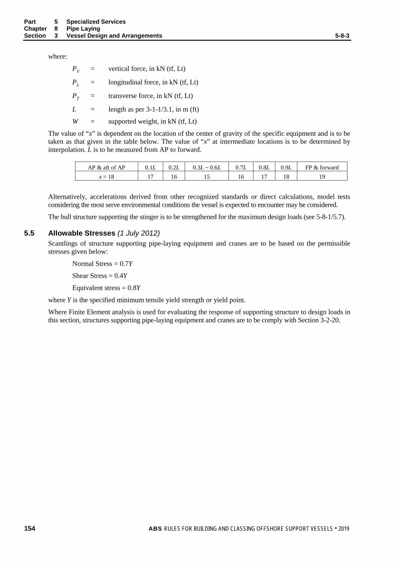
Part 5 Specialized Services Chapter 8 Pipe Laying Section 3 Vessel Design and Arrangements 5-8-3
where:
PV = vertical force, in kN (tf, Lt)
PL = longitudinal force, in kN (tf, Lt)
PT = transverse force, in kN (tf, Lt)
L = length as per 3-1-1/3.1, in m (ft)
W = supported weight, in kN (tf, Lt)
The value of “x” is dependent on the location of the center of gravity of the specific equipment and is to be taken as that given in the table below. The value of “x” at intermediate locations is to be determined by interpolation. L is to be measured from AP to forward.
AP & aft of AP 0.1L 0.2L 0.3L ~ 0.6L 0.7L 0.8L 0.9L FP & forward x = 18 17 16 15 16 17 18 19
Alternatively, accelerations derived from other recognized standards or direct calculations, model tests considering the most serve environmental conditions the vessel is expected to encounter may be considered.
The hull structure supporting the stinger is to be strengthened for the maximum design loads (see 5-8-1/5.7).
5.5 Allowable Stresses (1 July 2012) Scantlings of structure supporting pipe-laying equipment and cranes are to be based on the permissible stresses given below:
Normal Stress = 0.7Y
Shear Stress = 0.4Y
Equivalent stress = 0.8Y
where Y is the specified minimum tensile yield strength or yield point.
Where Finite Element analysis is used for evaluating the response of supporting structure to design loads in this section, structures supporting pipe-laying equipment and cranes are to be comply with Section 3-2-20.
154 ABS RULES FOR BUILDING AND CLASSING OFFSHORE SUPPORT VESSELS . 2019

P A R T S e c t i o n 4 : P i p e L a y i n g E q u i p m e n t a n d S y s t e m s
5 C H A P T E R 8 Pipe Laying
S E C T I O N 4 Pipe Laying Equipment and Systems
1 General (1 July 2012) Unless requested by the Owner and exceptions specified in 5-8-4/5, equipment and systems used solely for pipe laying operations are in general not subject to Classification by ABS, provided they are designed and constructed in compliance with an applicable recognized standard. The recognized standard used in design of pipe laying equipment and systems is to be specified by designer and acceptable to ABS. A manufacturer’s affidavit or other acceptable documentation to verify compliance with applicable recognized standards is to be submitted to ABS. Their installations and onboard testing are to be supervised in the aspects of operational safety as to reduce to a minimum any danger to persons on board and marine pollution, due regard to be paid to moving parts, hot surfaces and other hazards. Considerations are to be given to the consequences of the failure of systems and equipment essential to the safety of the vessel.
3 Pipe-lay Systems Arrangement
3.1 Control System A central control station is to be provided for controlling or coordinating the operations of the pipe laying equipment. The central control station is to be located at a position that allows the operating personnel to have a clear view of the pipe departure location and to provide an overview of all systems and activities associated with the pipe laying operations.
Means are to be provided for measuring the tension applied on the paid-out pipe, which is to be displayed at the control stations.
3.3 Communications The pipe laying central control station and the vessel station keeping control station are to be linked by a hard-wired communication system and a manually operated alarm system. Means of communications are to be provided between the central control station and the local control stations for the pay laying equipment.
5 Pipe-lay Equipment and Systems
5.1 Abandonment and Recovery System (A&R) 5.1.1 General
Abandonment and Recovery (A&R) system is to be provided to lay the pipe down on operation completion or the onset of harsh weather and for recovering the pipe after such an event. The system may consist of a hydraulic or electric motor driven traction winch, storage winch, and sheaves.
5.1.2 A&R System Capacity (1 July 2012) The A&R system is to be designed to provide adequate dynamic and brake holding capacity to control combined loads of the expected maximum tension generated by flooding the heaviest pipe and environmental forces such as waves, currents and tides, etc., exerting on the vessel as well as the laid-off pipes.
ABS RULES FOR BUILDING AND CLASSING OFFSHORE SUPPORT VESSELS . 2019 155

Part 5 Specialized Services Chapter 8 Pipe Laying Section 4 Pipe Laying Equipment and Systems 5-8-4
5.1.3 Braking A&R system is to be provided with a power control braking means such as regenerative, dynamic, counter torque breaking, controlled lowering or a mechanically controlled braking means capable of maintaining controlled lowering speeds.
Brakes are to be applied automatically upon loss of power or when the control lever is returned to neutral
5.1.4 Supporting Structures (1 July 2012) Detail drawings of the foundation and supporting structure on which the A&R winch are installed are to be submitted in accordance with 5-8-1/5.3 and 5-8-1/5.5. The foundations and supporting structures of the A&R winch and accessories are to be designed for the design static and dynamic loading conditions of the A&R winch defined in 5-8-4/5.1.2, using the allowable stresses formulated in 5-8-3/5.5.
5.3 Reels, Carousels, Pipe Racks and Support Structure (1 July 2012) Pipe reels and carousels are to be designed, constructed and installed in accordance with a recognized standard.
Pipe racks and reel support structure including the reinforcements for the hull are to be designed to adequately resist the load effects of pipes, risers or reels imposed on the supports in the severe storm, normal operating and transit conditions with the allowable stresses defined in 5-8-3/5.5. Considerations should also be given to the unit in damaged conditions, where the pipe racks and reel support structure are to withstand the load effects caused by the trim and heel of the vessel with the allowable stresses defined in 5-8-3/5.5.
5.5 J-lay/Flex-lay/Reel-lay Tower and Skid Frame (1 July 2012) J-lay, Flex-lay, Reel-lay towers and skid frames are to be designed in accordance with a recognized standard.
Detail drawings of the foundation and supporting structure on which the pipe-lay towers and skid frames rest or other stowage arrangements are installed are to be submitted for review.
For strength calculations of supports, the tower’s weight at extreme positions - upright and tilted position for J-lay/Flex-lay towers, upright elevation angles for pipe spooling-out and angled for pipe spooling-on and skid fleeting locations for Reel-lay towers, including associated center of gravity variations, static tension of the pipe and dynamic effects caused by environmental forces, are to be taken into account with the allowable stresses defined in 5-8-3/5.5.
5.7 Pipe Tensioners 5.7.1 General
Reliable tensioners are to be provided for keeping the tension in the pipeline while it is being lowered onto seabed.
5.7.2 Capacity (1 July 2012) The tensioner is to be designed to provide adequate dynamic and brake holding capacity to control combined loads of the tension generated by the paid-out pipeline, motions and environmental forces such as waves, currents and tides, etc. The required type depends on pipe specifics and configuration of the pipe-lay system.
5.7.3 Control The tensioners are to be provided with power controlled system operable at a remote control station to control and monitor the paid out length with feedback to the lay speed setting or vessel’s station keeping system
5.7.4 Supporting Structures (1 July 2012) The foundations and supporting structures of the tensioner and accessories are to be designed for the load effects of pipe tensioner capacity defined in 5-8-4/5.7.2 using the allowable stresses formulated in 5-8-3/5.5.
156 ABS RULES FOR BUILDING AND CLASSING OFFSHORE SUPPORT VESSELS . 2019

Part 5 Specialized Services Chapter 8 Pipe Laying Section 4 Pipe Laying Equipment and Systems 5-8-4
5.9 Hang-off Clamps Hang-off clamps are to be provided to hold the pipe when it is not suspended by tensioners or alternative means to hold the pipe such as A&R systems. Means are to be provided to ensure the holding power in case of electrical power black-out.
7 Offshore Construction Supporting Equipment
7.1 Remote Operated Vehicles (ROVs) When the vessel is equipped with work-class ROV to carry out underwater works, its handling system and control station are to be arranged in accordance with Sections 17 and 18 of the Underwater Vehicles Rules.
Deck foundations, fastening arrangements and vessel structures are to be designed in accordance with 5-5-3/5.
7.3 Pipe-laying Tracking System Where the pipe-laying tracking system interfaces with vessel’s data and control networks, provision is to be made to ensure that the operation or reliability of the vessel’s systems are not degraded.
ABS RULES FOR BUILDING AND CLASSING OFFSHORE SUPPORT VESSELS . 2019 157

P A R T S e c t i o n 5 : T e s t s , T r i a l s , a n d S u r v e y s
5 C H A P T E R 8 Pipe Laying
S E C T I O N 5 Tests, Trials, and Surveys
1 General Installation of the pipe laying equipment and systems on pipe laying vessels is to be to the satisfaction of the attending Surveyor.
Upon installation, functional integration tests of the pipe laying systems on board to the extent and as per the method agreed are to be carried out to the satisfaction of the attending Surveyor.
Position mooring equipment is to be tested in accordance with the specifications of the owner and in the presence of a Surveyor.
Dynamic positioning system is to be tested in accordance with Section 7 of the ABS Guide for Dynamic Positioning Systems.
158 ABS RULES FOR BUILDING AND CLASSING OFFSHORE SUPPORT VESSELS . 2019

P A R T C h a p t e r 9 : H e a v y L i f t
5 C H A P T E R 9 Heavy Lift
CONTENTS SECTION 1 General .................................................................................................. 161
1 Application ...................................................................................... 161 3 Scope .............................................................................................. 161 5 Classification ................................................................................... 161
5.1 Dual and Multi Purpose Vessels .................................................. 161 7 Submission of Data ......................................................................... 162
7.1 Hull Plans .................................................................................... 162 7.3 Crane Plans and Data ................................................................. 162 7.5 Design Analysis ........................................................................... 162 7.7 Additional Data ............................................................................ 162
SECTION 2 Seakeeping ........................................................................................... 163
1 Stability............................................................................................ 163 1.1 General........................................................................................ 163
3 Station Keeping ............................................................................... 163 3.1 General........................................................................................ 163 3.3 Station Keeping with Anchors and Cables................................... 163 3.5 Dynamic Positioning System ....................................................... 163
SECTION 3 Vessel Design and Equipment ........................................................... 164
1 Work Deck....................................................................................... 164 1.1 Reinforcements ........................................................................... 164 1.3 Arrangement ................................................................................ 164
3 Hull Arrangement and Strength ...................................................... 164 5 Cranes............................................................................................. 165 7 Supporting Structure Design Loads ................................................ 165
7.1 Acceleration Loads ...................................................................... 165 7.3 Lifting Loads ................................................................................ 165 7.5 Acceptable Stresses .................................................................... 165
9 Supporting Machinery and Systems ............................................... 166 9.1 Power System ............................................................................. 166 9.3 Heeling and Ballasting Systems .................................................. 166 9.5 Controls and Communications .................................................... 166
SECTION 4 Tests, Trials, and Surveys ................................................................... 167
1 General ........................................................................................... 167
ABS RULES FOR BUILDING AND CLASSING OFFSHORE SUPPORT VESSELS . 2019 159

APPENDIX 1 Intact Stability Requirements for Vessels Equipped to Lift ............. 168 1 Stability Information ........................................................................ 168
1.1 Specific Applicability .................................................................... 168 1.3 Definition ...................................................................................... 168
3 Intact Stability Requirements for Vessels Equipped to Lift ............. 169 3.1 Counter-ballasted and Non-counter-ballasted Vessels ................ 169 3.3 Additional Intact Stability Standards – Counter-ballasted
Vessels ........................................................................................ 170 TABLE 1 Values of Ch ........................................................................... 170 FIGURE 1 Load Radius .......................................................................... 169 FIGURE 2 Criteria after Accidental Loss of Crane Load
A1 ≥ 1.3 × A2 ........................................................................... 171 APPENDIX 2 Subsea Lifting ....................................................................................... 172
1 General ........................................................................................... 172 3 Initial Certification for In-air Lifting (mandatory) .............................. 172 5 Subsequent De-rating for Subsea Lifting (recommended) ............. 172
160 ABS RULES FOR BUILDING AND CLASSING OFFSHORE SUPPORT VESSELS . 2019
P A R T S e c t i o n 1 : G e n e r a l
5 C H A P T E R 9 Heavy Lift
S E C T I O N 1 General
1 Application The requirements in this Chapter apply to vessels intended for the lifting of heavy loads in oil drilling and production operations, offshore construction and/or salvage operations, with a lifting capacity of 160 metric tons or above. The services provided may consist of installation of production platform decks (integrated decks or topsides), decks supporting structures (jackets) as well as to support on-deck and subsea heavy lift operations and wind farm building projects.
3 Scope The following aspects are covered by the Classification requirements in this Chapter:
• Hull Structure
• Supporting structures for equipment applied in heavy lifting operations
• Equipment, machinery and installations for heavy lifting operations
• Equipment and machinery for anchoring and mooring related to heavy lifting operations
• Equipment and machinery for vessel positioning during heavy lifting operations
• Stability and floatability
5 Classification In accordance with Section 1-1-2 of the OSV Rules Supplement to the ABS Rules for Conditions of Classification (Part 1) and 5-1-1/5.1 of these Rules, the notation À A1 Offshore Support Vessel (Heavy Lift) will be assigned to vessels equipped with heavy lift offshore crane or cranes according to the Lifting Appliances Guide, built in compliance with these requirements and other relevant sections of these Rules.
The above notation will be assigned to purpose-built vessels having all heavy lifting equipment permanently installed and classified by ABS. Such vessels will be distinguished in the Record with their assigned notation and information on the heavy lifting capabilities. Heavy lifting systems will be subject to the annual surveys.
5.1 Dual and Multi Purpose Vessels Vessels intended for heavy lifting operations on offshore installations may be classed with combinations of the applicable notations for the relevant service as explained in Section 5-1-1.
In such instances, the dual or multipurpose vessel is to be designed and built to these requirements, as well as to those applicable for the particular additional service or services.
ABS RULES FOR BUILDING AND CLASSING OFFSHORE SUPPORT VESSELS . 2019 161

Part 5 Specialized Services Chapter 9 Heavy Lift Section 1 General 5-9-1
7 Submission of Data In general, in addition to the plans listed in Section 1-1-4 of the OSV Rules Supplement to the ABS Rules for Conditions of Classification (Part 1), the following plans, calculations and particulars are to be submitted.
7.1 Hull Plans For a list of drawings to be submitted together with the Trim and Stability Booklet for ABS review, refer to 3-3-A1/17.
7.3 Crane Plans and Data i) General arrangement, assembly plans and description of operating procedure and design service
temperature
ii) Dead, live and dynamic loads. Environmental loads including effects of wind, snow and ice. Load swing caused by non-vertical lifts. Load due to the list and/or trim of the vessel or structure.
iii) Maximum reactions and overturning moments
iv) Details of the principal structural parts, including crane pedestal, foundation and other crane supporting structure
v) Welding details and procedures
vi) Crane capacity rating charts
vii) Wire rope specifications
viii) Material specifications
ix) Details of heave compensation arrangements if applicable
x) Where applicable, details of swing circle assembly, arrangement of hold-down bolts, size, material, grade and pretensioning together with method used for pretensioning
xi) Equipment for positioning during heavy weight lifting operations
7.5 Design Analysis The following calculations are to be submitted:
• Calculations demonstrating the adequacy of the vessel’s stability during heavy weight lifting operations. See also 5-9-2/1.
• Calculations demonstrating adequacy of propulsion power required for the vessel to maintain station during heavy weight lifting operations.
• Calculations demonstrating strength of the crane and supporting structures.
7.7 Additional Data The following items are also to be submitted:
• Plans of the electric installations of the crane
• Diagrams of electrical, hydraulic and pneumatic systems and equipment for power supply and control systems for the cranes
• Assembly plan showing principal dimensions of the crane and limiting positions of its movable parts
• Piping diagrams for ballast and/or anti-heeling systems
• Crane manual for each crane installed on board, see 5-9-4/1
162 ABS RULES FOR BUILDING AND CLASSING OFFSHORE SUPPORT VESSELS . 2019
P A R T S e c t i o n 2 : S e a k e e p i n g
5 C H A P T E R 9 Heavy Lift
S E C T I O N 2 Seakeeping
1 Stability
1.1 General In addition to the stability criteria in Section 3-3-1, each vessel is to satisfy the intact stability requirements in Appendix 5-9-A1. Stability calculations and corresponding information for the Master are to be submitted for review and approval. The submission of evidence showing approval by an Administration of stability of the vessel for the lifting operations in accordance with a recognized standard may be accepted.
The dynamic load chart for each crane shall be included in the Trim and Stability Booklet and shall be posted at the crane operator's station in the clear view of the crane operator.
3 Station Keeping
3.1 General Heavy lifting vessels are to be capable of maintaining their positions safely during heavy lifting operations. The means to maintain position may be a mooring system with anchors, a dynamic positioning system or combination of both.
3.3 Station Keeping with Anchors and Cables Position mooring with anchors, cables and mooring winches when used to maintain the vessel’s position during heavy lifting operations, are to comply with the requirements for the class notation à (see Section 3-4-1 of the MODU Rules). Safety precautions are to be considered to prevent damaging seabed equipment and installations by anchor deployment, recovery and station keeping.
3.5 Dynamic Positioning System Dynamic positioning systems, when used to maintain the vessel’s position during heavy lifting operations, are to comply with the requirements for the class notation DPS-2 or DPS-3 (see the ABS Guide for Dynamic Positioning Systems).
ABS RULES FOR BUILDING AND CLASSING OFFSHORE SUPPORT VESSELS . 2019 163

P A R T S e c t i o n 3 : V e s s e l D e s i g n a n d E q u i p m e n t
5 C H A P T E R 9 Heavy Lift
S E C T I O N 3 Vessel Design and Equipment
1 Work Deck
1.1 Reinforcements The work deck is to be strengthened for the specified design loads and non-uniform loadings are to be specified. It is recommended that an allowance for corrosion, wear and tear be added on top of the Rules requirement. The strong points, if required, are to be situated, as far as practicable, on crossings of bulkheads and web frames. All deck stiffeners are to be double-continuous welded.
1.3 Arrangement 1.3.1
It is recommended that fuel tanks are not located directly under the working decks, where hot works would be carried out, unless a void space, hold, store, cofferdam or water ballast tank forms a separation space between the working deck and fuel tank.
1.3.2 The working deck, as far as possible, is to be kept unobstructed, clear of engine room intakes and exhaust from tank vents and mooring equipment. Tank vents, mooring and deck access provisions are preferably to be grouped in way of the aft deck, boom rest and/or forecastle.
3 Hull Arrangement and Strength Where a mono-hull heavy lift vessel is designed with dual drafts to meet the necessary stability for heavy lifts and higher speed for transit, the vessel’s scantling calculations are to be carried out for the two draft conditions.
Where sponsons are added to the hull in way of the crane location, sufficient distance between the underside of the sponsons and the waterline is to be maintained to reduce wave-sponson interaction. In any case, the underside of the sponsons is to be strengthened to account of wave-sponsons interaction based on 3-2-2/5 and 3-2-4/13 requirements.
In crane lifting conditions, the sponsons are to be designed to be immersed, while complying with freeboard requirements, and to avoid emergence of the sponsons out of the water during the operation.
Hogging or sagging effects resulting from the crane’s location are to be considered in the hull girder strength calculations. Where the crane is located at vessel side, torsional stress conditions are to be to be taken into account.
The most unfavorable load conditions during lifting operations are to be taken into account, including static and dynamic loads considering environmental conditions.
164 ABS RULES FOR BUILDING AND CLASSING OFFSHORE SUPPORT VESSELS . 2019

Part 5 Specialized Services Chapter 9 Heavy Lift Section 3 Vessel Design and Equipment 5-9-3
5 Cranes
5.1 Any crane permanently installed on board the crane unit and intended for operations other than supply of provisions and maintenance of the unit is to be certified by ABS in accordance with Chapter 2 of the Lifting Appliances Guide or API Spec. 2C.
Mobile cranes not permanently attached to the unit structure, such as crawler cranes, are not required to be certified. Means for securing the crane in parked position at sea in vessel’s transit mode is to be provided taking into account environmental load conditions.
For the cranes used for subsea lifting, see Appendix 5-9-A2.
7 Supporting Structure Design Loads
7.1 Acceleration Loads Ship structures supporting cranes are to be designed considering acceleration loads given below. Acceleration loads need not be combined with normal lifting operation loads of the cranes.
PV = 0.102*[(x – L/70)]W kN (tf)
= 0.102*[(x – L/229.7)]W Lt
PL = PT = 0.5W
where:
PV = vertical force, in kN (tf, Lt)
PL = longitudinal force, in kN (tf, Lt)
PT = transverse force, in kN (tf, Lt)
L = length as per 3-1-1/3.1, in m (ft)
W = supported weight, in kN (tf, Lt)
The value of “x” is dependent on the location of the center of gravity of the specific equipment and is to be taken as that given in the table below. The value of “x” at intermediate locations is to be determined by interpolation. L is to be measured from AP to forward.
AP & aft of AP 0.1L 0.2L 0.3L ~ 0.6L 0.7L 0.8L 0.9L FP & forward x = 18 17 16 15 16 17 18 19
Alternatively, accelerations derived from other recognized standards or direct calculations, model tests considering the most serve environmental conditions the vessel is expected to encounter may be considered.
7.3 Lifting Loads Maximum expected operational loads are to be applied for calculating scantlings of supporting structure. Lifting loads shall consider a minimum dynamic factor according to the Lifting Appliances Guide or one submitted by the crane manufacturer, if that be greater.
7.5 Acceptable Stresses Scantlings of structure supporting cranes are to be based on the permissible stresses given below:
Normal Stress = 0.7Y
Shear Stress = 0.4Y
Equivalent stress = 0.8Y
where Y is the specified minimum tensile yield strength or yield point.
ABS RULES FOR BUILDING AND CLASSING OFFSHORE SUPPORT VESSELS . 2019 165

Part 5 Specialized Services Chapter 9 Heavy Lift Section 3 Vessel Design and Equipment 5-9-3
9 Supporting Machinery and Systems
9.1 Power System 9.1.1 Crane with Self-contained or Independent Power Plant
Where the crane is fitted with self-contained or independent power plant with the prime mover and its auxiliary systems including the power take-off means and the starting system, the power plant is to be sized such that the minimum required hook velocity can be achieved when lifting the corresponding rated load, taking into account simultaneous operations (hoist, luff, swing) requirements, efficiencies of the power plant and the system components.
Gasoline engines as prime movers are prohibited.
Engine exhausts are to be equipped with spark arrestors and all exhaust systems are to be guarded in areas where contact by personnel in the performance of their normal duties is possible.
Fuel tanks fills and overflows are not to run close to exhausts. Fuel tanks are to be equipped with filler necks and caps designed to prevent fuel contamination from external sources. Removable caps, where fitted, are to be securely tethered to the filler.
9.1.2 Cranes Driven by Vessel’s Power Systems Where the crane is driven by vessel’s power systems, either hydraulic or electric, the vessel’s main power plant is to be sized with sufficient capacity to operate the crane under the load conditions defined in 5-9-3/9.1.1 and arranged to ensure the functioning of all safety equipment and essential services for vessel station keeping and floatability keeping are not impaired, jeopardized and degraded.
9.3 Heeling and Ballasting Systems Where heeling systems are provided to counteract the crane’s overturning moment, the systems are to be designed to ensure that the vessel is capable of withstanding the sudden loss of the hook load in each condition of loading and operation. The free surface effects are to be considered for those tanks which are ballasted. Specific reference may be made to 5-9-A1/3.3.
9.5 Controls and Communications 9.5.1 Controls
All controls used during the normal crane operating cycle are to be located within easy reach of the operator while at the operator’s station.
Control levers for boom hoist, load hoist, swing and boom telescope (when applicable) are to be returned automatically to their center (neutral) positions on release. Control operations and functions are to be clearly marked and easily visible by the operator at the operator’s control station.
As appropriate, monitoring is to indicate availability of power, air pressure, hydraulic pressure, motor running and slewing brake mechanism engagement.
Cranes are to be provided with an overload-protection system. Motor running protection is to be provided and is to be set between 100% and 125% of motor rated current.
Provisions are to be made for emergency stop of the crane operations by the operator at the operator’s control station.
9.5.2 Communications Hard-wired communications is to be provided between the crane operator’s control station and the vessel’s station keeping control station.
166 ABS RULES FOR BUILDING AND CLASSING OFFSHORE SUPPORT VESSELS . 2019

P A R T S e c t i o n 4 : T e s t s , T r i a l s , a n d S u r v e y s
5 C H A P T E R 9 Heavy Lift
S E C T I O N 4 Tests, Trials, and Surveys
1 General To assist in survey, the vessel is to be provided with approved crane manuals on board, accessible to the Surveyor, containing full information concerning design standard, operation, erection, dismantling and transportation; all limitations during normal and emergency operations with respect to safe working load, safe working moment, maximum wind, maximum heel and trim, design temperatures and braking systems; all safety devices; diagrams for electrical, hydraulic and pneumatic systems and equipment, materials used in construction, welding procedures and extent of non-destructive testing; guidance on maintenance and periodic inspection.
Installation of the crane, supporting machinery and systems on the vessels is to be to the satisfaction of the attending Surveyor.
After each crane has been erected on board, and before it is placed in service, the functional integration tests of the crane systems and load tests are to be conducted in the presence of the Surveyor. A record of these tests and other information concerning initial certification is to be readily available.
Position mooring equipment is to be tested in accordance with the specifications of the owner and in the presence of a Surveyor.
Dynamic positioning system is to be tested in accordance with Section 7 of the ABS Guide for Dynamic Positioning Systems.
ABS RULES FOR BUILDING AND CLASSING OFFSHORE SUPPORT VESSELS . 2019 167

P A R T A p p e n d i x 1 : I n t a c t S t a b i l i t y R e q u i r e m e n t s f o r V e s s e l s E q u i p p e d t o L i f t
5 C H A P T E R 9 Heavy Lift
A P P E N D I X 1 Intact Stability Requirements for Vessels Equipped to Lift
1 Stability Information
1.1 Specific Applicability This appendix applies to each vessel that:
i) Is equipped for heavy lifting of cargo or other objects; and
ii) Has a maximum heeling moment due to hook load greater than or equal to:
(0.67)(∆)(GM)(F/B) meter-metric tons (foot-long tons)
where:
∆ = displacement of the vessel with the hook load included, in metric (long) tons
GM = metacentric height with hook load included, in meters (feet)
F = freeboard to the deck edge amidships, in meters (feet)
B = beam, in meters (feet)
1.3 Definition As used in this Appendix.
i) Hook load means the weight of the object lifted by the crane.
ii) Load radius means the distance illustrated in 5-9-A1/Figure 1
iii) Crane Heeling Moment is the maximum heeling moment developed by multiplying the weight of the hook load and boom by the horizontal distance from vessel’s centerline to the hook load and boom center of gravity, considering the full range of crane elevations and weights. The resulting heeling moment is to be converted to a heeling arm at zero degrees by dividing it by the vessel displacement. The heeling arm is to be assumed constant for all heel angles.
iv) Equilibrium heel angle is the angle of heel under the combined effects of the hook load, counter-ballasting and a beam wind.
168 ABS RULES FOR BUILDING AND CLASSING OFFSHORE SUPPORT VESSELS . 2019

Part 5 Specialized Services Chapter 9 Heavy Lift Appendix 1 Intact Stability Requirements for Vessels Equipped to Lift 5-9-A1
FIGURE 1 Load Radius
CL Load Radius
3 Intact Stability Requirements for Vessels Equipped to Lift (1 July 2012)
3.1 Counter-ballasted and Non-counter-ballasted Vessels 3.1.1
Each vessel that is equipped to lift is to comply, by design calculations, with this section under the following conditions:
i) Either for each loading condition (see 3-3-A1/7) and pre-lift condition, or the range of conditions, including pre-lift conditions, delineated by the lifting operations guidelines contained in the trim and stability booklet; and
ii) Crane Heeling Moment, and
iii) The effect of beam wind on the projected area of the vessel (including deck cargo) should be evaluated for 25.7 m/s (50 knots) wind speed. Should a lesser wind speed be used, that wind speed shall be listed in the trim and stability booklet as an operational restriction during lifting operations.
The wind heeling moment shall be calculated as:
P × A × H N-m (kgf-m, lbf-ft)
where
P = wind pressure, calculated as per below
A = projected lateral area, in square meters (square feet), of all exposed surfaces (including deck cargo), in the upright condition
H = vertical distance, in meters (feet), from the center of A to the center of the underwater lateral area or approximately to the one-half draft point
ABS RULES FOR BUILDING AND CLASSING OFFSHORE SUPPORT VESSELS . 2019 169
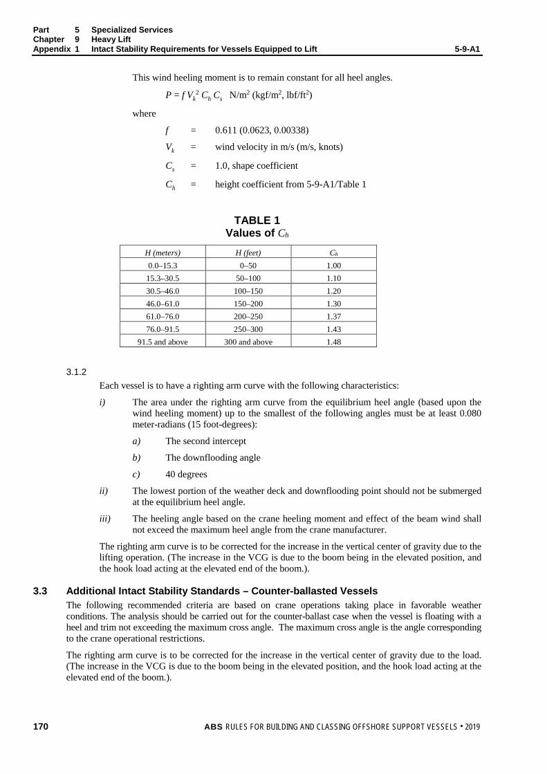
Part 5 Specialized Services Chapter 9 Heavy Lift Appendix 1 Intact Stability Requirements for Vessels Equipped to Lift 5-9-A1
This wind heeling moment is to remain constant for all heel angles.
P = f Vk2 Ch Cs N/m2 (kgf/m2, lbf/ft2)
where
f = 0.611 (0.0623, 0.00338)
Vk = wind velocity in m/s (m/s, knots)
Cs = 1.0, shape coefficient
Ch = height coefficient from 5-9-A1/Table 1
TABLE 1 Values of Ch
H (meters) H (feet) Ch 0.0–15.3 0–50 1.00
15.3–30.5 50–100 1.10 30.5–46.0 100–150 1.20 46.0–61.0 150–200 1.30 61.0–76.0 200–250 1.37 76.0–91.5 250–300 1.43
91.5 and above 300 and above 1.48
3.1.2 Each vessel is to have a righting arm curve with the following characteristics:
i) The area under the righting arm curve from the equilibrium heel angle (based upon the wind heeling moment) up to the smallest of the following angles must be at least 0.080 meter-radians (15 foot-degrees):
a) The second intercept
b) The downflooding angle
c) 40 degrees
ii) The lowest portion of the weather deck and downflooding point should not be submerged at the equilibrium heel angle.
iii) The heeling angle based on the crane heeling moment and effect of the beam wind shall not exceed the maximum heel angle from the crane manufacturer.
The righting arm curve is to be corrected for the increase in the vertical center of gravity due to the lifting operation. (The increase in the VCG is due to the boom being in the elevated position, and the hook load acting at the elevated end of the boom.).
3.3 Additional Intact Stability Standards – Counter-ballasted Vessels The following recommended criteria are based on crane operations taking place in favorable weather conditions. The analysis should be carried out for the counter-ballast case when the vessel is floating with a heel and trim not exceeding the maximum cross angle. The maximum cross angle is the angle corresponding to the crane operational restrictions.
The righting arm curve is to be corrected for the increase in the vertical center of gravity due to the load. (The increase in the VCG is due to the boom being in the elevated position, and the hook load acting at the elevated end of the boom.).
170 ABS RULES FOR BUILDING AND CLASSING OFFSHORE SUPPORT VESSELS . 2019

Part 5 Specialized Services Chapter 9 Heavy Lift Appendix 1 Intact Stability Requirements for Vessels Equipped to Lift 5-9-A1
i) For any condition of loading and crane heeling moment, the first intercept of the heeling arm curve with the righting arm curve (equilibrium point) is to occur prior to submergence of the deck edge.
The following requirements are also to be met, with the vessel at the maximum allowable vertical center of gravity, to provide adequate stability in case of sudden loss of crane load:
ii) The residual area between the first intercept and the angle of downflooding or the second intercept, whichever occurs first, (area A1 in Figure 2) is not to be less than 30% in excess of area A2 in 5-9-A1/Figure 2.
iii) The angle of the first intercept between the righting lever curve after loss of crane load and the maximum permissible counter ballast lever curve is not to exceed 15° (angle of equilibrium after loss of crane load).
FIGURE 2 Criteria after Accidental Loss of Crane Load (1 July 2012)
A1 ≥ 1.3 × A2
A1
A2
θf
θc
GZ(1) GZ(2)
HM(2)
HM(1)
GZ(1)
Heeling and RightingMoment
Heel
GZ(1) = righting moment curve at the displacement corresponding to the vessel without hook load.
GZ(2) = righting moment curve at the displacement corresponding to the vessel with hook load.
HM(1) = heeling moment curve due to the heeling moment of the counter-ballast at the displacement without hook load.
HM(2) = heeling moment curve due to the combined heeling moments of the hook load and the counter-ballast at the displacement with hook load.
θf = Limit of area integration to the downflooding angle or second intercept on the counter-ballasted side of the vessel.
θc = Limit of area integration to the angle of static equilibrium due to the combined hook load and counter-ballast heeling moment.
ABS RULES FOR BUILDING AND CLASSING OFFSHORE SUPPORT VESSELS . 2019 171
P A R T A p p e n d i x 2 : S u b s e a L i f t i n g
5 C H A P T E R 9 Heavy Lift
A P P E N D I X 2 Subsea Lifting
1 General Subsea lifting is normally the operation of a lifting appliance handling a load which will be lowered through the splash zone and either held at an intermediate level, released on the seabed, or retrieved back through the splash zone on to the vessel. Lifting appliances must first be certified by ABS for in air lifting according to the Lifting Appliances Guide and/or other recognized standards. They may then be eligible for subsea lifting provided these subsea lifts are engineered on a case by case basis by a responsible party associated with subsea lifting for the appropriate environmental conditions. This will result in some degree of de-rating the lifting appliance from its ABS certified in air capacity. In principle ABS does not approve these subsea lifts as the degree of variance precludes a general rule for this type of operation. In this appendix, ABS provides a recommended sequence to be followed for de-rating lifting appliances from the in air lifting mode to the subsea lifting mode.
3 Initial Certification for In-air Lifting (mandatory) i) The lifting appliance structure is to be initially approved according to the Lifting Appliances Guide
for ship, offshore or heavy lift applications. The offshore application will additionally include approval to API Spec. 2C.
ii) The machinery aspects such as winches, cylinders, accumulators, electric circuits will be approved according to the Steel Vessel Rules or other recognized standards.
iii) Survey is required during manufacturing.
iv) Testing is required at various stages during manufacturing and finally at installation.
5 Subsequent De-rating for Subsea Lifting (recommended) i) The basic dynamic factors used for amplifying the lifted loads are to be derived according to API
Spec. 2C from purchaser supplied lifting appliance boom tip velocities for the specific vessel the lifting appliance is to be mounted on.
ii) The use of active heave compensation, passive heave compensation, constant tension, or any combination of these systems can be decided by the purchaser.
iii) The use of manual overload protection systems or automatic overload protection systems can be decided by the purchaser.
iv) Modeling of the lifting appliance system should take the following aspects into account: basic dynamic factors based on boom tip velocities, buoyancy, added mass, drag, rope weight, resonance, sea bed suction.
v) Modeling results should produce revised dynamic factors that can be used to de-rate the crane from the initial certified capacity for in air lifts.
vi) A risk analysis according to the ABS Guide for Risk Assessment Applications for the Marine and Offshore Oil and Gas Industries should be conducted.
vii) A failure mode and effects analysis (FMEA) should be conducted and this should include vessel power failure.
viii) Each subsea lift operation is to have its own unique modeling and analyses scenarios.
172 ABS RULES FOR BUILDING AND CLASSING OFFSHORE SUPPORT VESSELS . 2019

P A R T C h a p t e r 1 0 : W e l l I n t e r v e n t i o n
5 C H A P T E R 10 Well Intervention
CONTENTS SECTION 1 General .................................................................................................. 176
1 Application ...................................................................................... 176 3 Scope and Limitations ..................................................................... 176 5 Definitions ....................................................................................... 176
5.1 Well Intervention Systems ........................................................... 176 5.3 Permanent Well Intervention Systems ........................................ 176 5.5 Temporary Well Intervention Systems ......................................... 176 5.7 Well Intervention Ready .............................................................. 177
7 Class Notations ............................................................................... 177 7.1 Permanent Well Intervention Systems ........................................ 177 7.3 Temporary Well Intervention Systems ......................................... 177 7.5 Well Intervention Ready .............................................................. 177 7.7 Change of Class Notations .......................................................... 177 7.9 Dual and Multi Purpose Vessels .................................................. 177 7.11 Selection of Class ........................................................................ 177 7.13 Administration Requirements ...................................................... 177
9 Plans and Data to be Submitted ..................................................... 177 FIGURE 1 Well Intervention System Classification ................................ 178
SECTION 2 Well Intervention Ready ...................................................................... 179
1 General ........................................................................................... 179 3 Riserless Well Intervention (WI-READY) ........................................ 179
3.1 Arrangements .............................................................................. 179 3.3 Deck Structure ............................................................................. 180 3.5 Moon Pools ................................................................................. 180 3.7 Lifting Appliances, Hoisting Equipment, and Supporting
Structure ...................................................................................... 180 3.9 Material Storage Tanks for Well Intervention ............................... 180 3.11 Spill Containment ........................................................................ 180 3.13 Supporting Facilities for Seabed Equipment Intervention
Systems....................................................................................... 180 3.15 Classified Areas .......................................................................... 181 3.17 Safety Systems ........................................................................... 181 3.19 Vessel Station Keeping Capability ............................................... 182 3.21 Well Intervention Equipment and Systems .................................. 182
ABS RULES FOR BUILDING AND CLASSING OFFSHORE SUPPORT VESSELS . 2019 173

5 Riser-Based Well Intervention (WIR-READY) ................................ 182 5.1 General ........................................................................................ 182 5.3 Crude Fluids Storage Tanks ........................................................ 182 5.5 Chemical Injection System ........................................................... 183 5.7 Spill Containment ......................................................................... 183 5.9 Area Classification ....................................................................... 183 5.11 Safety Systems ............................................................................ 183 5.13 Vessel Station Keeping Capability ............................................... 184 5.15 Well Intervention Equipment and Systems .................................. 184
SECTION 3 Temporary Well Intervention Systems ............................................... 185
1 General ........................................................................................... 185 1.1 Applications ................................................................................. 185 1.3 Documentation Requirements ..................................................... 185
3 Riserless Well Intervention ............................................................. 186 3.1 Arrangement ................................................................................ 186 3.3 Temporary Equipment and Machinery ......................................... 186 3.5 Independent Tanks ...................................................................... 186 3.7 Chemical Injection System ........................................................... 186 3.9 Spill Containment ......................................................................... 186 3.11 Classified Areas ........................................................................... 187 3.13 Safety Systems ............................................................................ 187 3.15 Well Intervention Equipment and Systems .................................. 187
5 Riser-Based Well Intervention ........................................................ 188 5.1 General ........................................................................................ 188 5.3 Temporary Equipment and Machinery ......................................... 188 5.5 Temporary Crude Fluids Storage Tank ........................................ 188 5.7 Chemical Injection System ........................................................... 188 5.9 Spill Containment ......................................................................... 188 5.11 Classified Areas ........................................................................... 188 5.13 Safety Systems ............................................................................ 189 5.15 Well Intervention Equipment and Systems .................................. 189
7 Onboard Surveys During Installation .............................................. 189 SECTION 4 Permanent Well Intervention Systems ............................................... 190
1 General ........................................................................................... 190 3 Riserless Well Intervention ............................................................. 190
3.1 General ........................................................................................ 190 3.3 Arrangement of Well Intervention Equipment and Machinery ...... 190 3.5 Crude Fluids Storage Tanks ........................................................ 190 3.7 Chemical injection system ........................................................... 190 3.9 Spill containment ......................................................................... 190 3.11 Classified Areas ........................................................................... 190 3.13 Safety Systems ............................................................................ 190 3.15 Well Intervention Equipment and Systems .................................. 191
174 ABS RULES FOR BUILDING AND CLASSING OFFSHORE SUPPORT VESSELS . 2019

5 Riser-Based Well Intervention ........................................................ 191 5.1 General........................................................................................ 191 5.3 Arrangements of Well Intervention Equipment and Machinery .... 191 5.5 Crude Fluids Storage Tanks ........................................................ 192 5.7 Chemical Injection System .......................................................... 192 5.9 Spill Containment ........................................................................ 193 5.11 Classified Areas .......................................................................... 193 5.13 Safety Systems ........................................................................... 194 5.15 Well Intervention Equipment and Systems .................................. 194
7 Vessels without Well Intervention Permanent Class Notation ........ 195 7.1 Riserless Well Intervention Unit ................................................... 195 7.3 Riser-based Well Intervention Unit .............................................. 195
SECTION 5 Well Intervention Equipment and Systems ....................................... 196
1 General ........................................................................................... 196 3 Well Entry and Intervention Equipment .......................................... 196
3.1 General........................................................................................ 196 3.3 Equipment and Systems Certification Requirements .................. 196
5 Materials for Well Intervention Systems and Components ............. 197 7 Welding and Nondestructive Examination ...................................... 197 9 Normative References .................................................................... 197
SECTION 6 Surveys ................................................................................................. 198
1 General ........................................................................................... 198 3 Onboard Surveys During Installation .............................................. 198
3.1 Operation Procedures ................................................................. 198 3.3 Installation and Testing................................................................ 198
5 Commissioning Surveys of the Well Intervention Systems ............ 198
ABS RULES FOR BUILDING AND CLASSING OFFSHORE SUPPORT VESSELS . 2019 175

P A R T S e c t i o n 1 : G e n e r a l
5 C H A P T E R 10 Well Intervention
S E C T I O N 1 General
1 Application The requirements in this Chapter apply to offshore support vessels that are equipped, either permanently or temporarily, for carrying out well intervention services, or are capable of being equipped for such services.
3 Scope and Limitations (2018) This Chapter addresses the safety aspects related to well intervention systems either temporarily or permanently installed on board vessels classed with ABS.
5 Definitions (2018)
5.1 Well Intervention Systems A well intervention is any operations carried out on an oil or gas well during or at the end of its productive life, which alters the well state and/or well geometry, provides well diagnostics, or manages the production of the well. It may involve re-entry into a well and/or retrieval of a tree. Typical well intervention operations may include pumping, wellhead and Christmas tree maintenance, slickline, braided line, coiled tubing, snubbing, workover, etc.
Well intervention systems are the facilities installed on vessels or mobile offshore drilling units (MODU)/ mobile offshore units (MOU) for the purpose of well diagnostics, managing the production of the well and seabed equipment. The following two categories of subsea well intervention systems are addressed herein:
5.1.1 Riserless Well Intervention (RLWI) System RLWI system consists of equipment capable of direct access to the wellbore without requiring the use of rigid riser connected to the subsea stack. Normally, no hydrocarbons are transported to the well intervention vessel/unit, but flushed back into the well through the lubricator system during normal operations.
5.1.2 Riser-based Well Intervention (RBWI) System Riser-based Well Intervention system generally consists of equipment capable of downhole well contact and a riser system with pressure-containing flow conduits and control circuits with the capability for introduction of hydrocarbons onboard into the well intervention vessel/unit onboard and possible injection of well stimulation fluids into the wellbore.
5.3 Permanent Well Intervention Systems Well intervention systems installed on board a vessel or MODU/MOU for at least 12 months are considered permanent, notwithstanding if the system is or is not in operation.
5.5 Temporary Well Intervention Systems Well intervention systems installed on board a vessel or MODU/MOU for less than 12 months are considered temporary.
176 ABS RULES FOR BUILDING AND CLASSING OFFSHORE SUPPORT VESSELS . 2019

Part 5 Specialized Services Chapter 10 Well Intervention Section 1 General 5-10-1
5.7 Well Intervention Ready Vessels or MODUs/MOUs that have been designed for well intervention operations, but the well intervention system has not been installed on board, are considered “well intervention ready”.
7 Class Notations
7.1 Permanent Well Intervention Systems (2018) Vessels fitted with permanent well intervention systems that comply with Section 5-10-4 will be assigned the classification À A1 Offshore Support Vessel (WI) for Riserless Well Intervention (RLWI) or À A1 Offshore Support Vessel (WIR) for Riser-based Well Intervention (RBWI).
7.3 Temporary Well Intervention Systems (2018) Vessels fitted with temporary well intervention systems are to comply with the requirements in Section 5-10-3 of these Rules for maintaining classification status.
7.5 Well Intervention Ready (2018) Vessels designed to be “well intervention ready” that comply with Section 5-10-2 will be assigned the classification À A1 Offshore Support Vessel (WI-READY) or À A1 Offshore Support Vessel (WIR-READY). The Class Notation depends on the well intervention systems installed onboard (refer to 5-10-1/7.1).
7.7 Change of Class Notations The installation or removal of the well intervention systems on board vessels is to be notified to ABS in order to re-assess the compliance with the requirements of this Chapter. The class notations will be modified as necessary to reflect the new status of the vessel, see 5-1-1/5.5.
7.9 Dual and Multi Purpose Vessels Vessels intended for well intervention operations and providing additional services may be classed with combinations of the applicable notations for the relevant service as explained in Section 5-1-1.
In such instances, the dual or multipurpose vessel is to be designed and built to these requirements, as well as to those applicable for the particular additional service or services.
7.11 Selection of Class (2018) It is the responsibility of the Owner to select the class most suitable for the intended service and ensure that the vessel is operated in a safe environment with respect to the risk associated with the anticipated operation activities.
7.13 Administration Requirements (1 July 2012) Requirements additional to those given in this Chapter may be imposed by the National Administration with whom the vessel is registered or by the Administration within whose territorial jurisdiction the vessel is intended to operate.
Approval of structural fire protection, fire extinguishing equipment and/or stability of the vessel by a National Administration, in accordance with requirements equivalent to those by class, may be considered as complying with the class requirements provided such approval can be satisfactorily documented.
9 Plans and Data to be Submitted (2016) In general, in addition to the plans listed in Section 1-1-4 of the OSV Rules Supplement to the ABS Rules for Conditions of Classification (Part 1), the following drawings of well intervention equipment and vessel particulars are to be submitted:
ABS RULES FOR BUILDING AND CLASSING OFFSHORE SUPPORT VESSELS . 2019 177
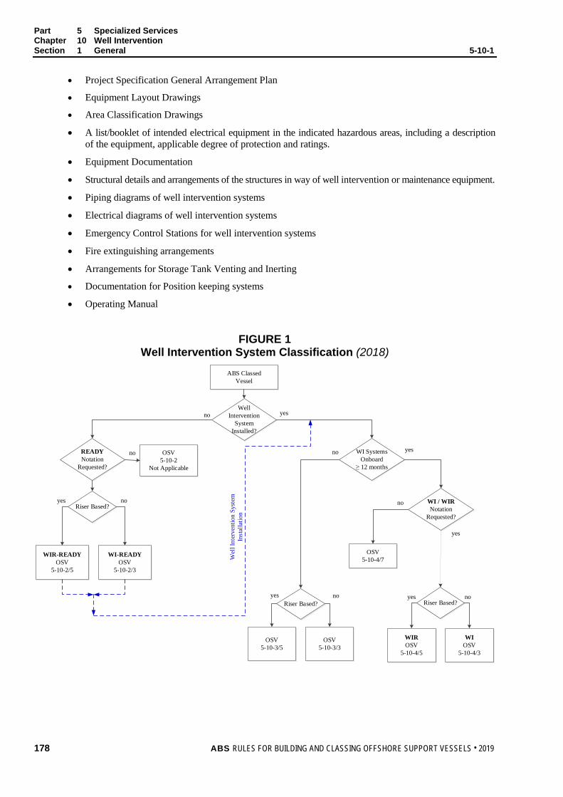
Part 5 Specialized Services Chapter 10 Well Intervention Section 1 General 5-10-1
• Project Specification General Arrangement Plan
• Equipment Layout Drawings
• Area Classification Drawings
• A list/booklet of intended electrical equipment in the indicated hazardous areas, including a description of the equipment, applicable degree of protection and ratings.
• Equipment Documentation
• Structural details and arrangements of the structures in way of well intervention or maintenance equipment.
• Piping diagrams of well intervention systems
• Electrical diagrams of well intervention systems
• Emergency Control Stations for well intervention systems
• Fire extinguishing arrangements
• Arrangements for Storage Tank Venting and Inerting
• Documentation for Position keeping systems
• Operating Manual
FIGURE 1 Well Intervention System Classification (2018)
ABS ClassedVessel
READYNotation
Requested?
OSV5-10-2
Not Applicable
WI SystemsOnboard
≥ 12 months
WIROSV
5-10-4/5
WIOSV
5-10-4/3
WI-READYOSV
5-10-2/3
WIR-READYOSV
5-10-2/5
no
OSV5-10-3/3
OSV5-10-3/5
Well Intervention
SystemInstalled?
yesno
WI / WIRNotation
Requested?
OSV5-10-4/7
no
no
yes
yes
noyes
Riser Based?noyes noyes
Riser Based?
Riser Based?
Wel
l Int
erve
ntio
n Sy
stem
In
stal
latio
n
178 ABS RULES FOR BUILDING AND CLASSING OFFSHORE SUPPORT VESSELS . 2019

P A R T S e c t i o n 2 : W e l l I n t e r v e n t i o n R e a d y
5 C H A P T E R 10 Well Intervention
S E C T I O N 2 Well Intervention Ready
1 General (2018) Vessels that have been designed for well intervention operations, but the well intervention equipment and systems have not been fully installed on board are to comply with the requirements in this Section when the class notation WI-READY or WIR-READY has been requested by the Owner.
3 Riserless Well Intervention (WI-READY)
3.1 Arrangements (2018) Equipment layout and work areas associated with the well intervention activities are to be arranged with the following design principles to minimize the risk of hazards to personnel, property, and environment:
i) Keep hazardous machinery operation out of harm’s way to personnel
• Providing for adequate arrangements for escape and evacuation
• Provisions for safe access for maintenance and inspection.
• Prevention of dropped object hazards to personnel and assets
• Equipping with effective emergency response
ii) Keep hazardous materials away from personnel
• Separation of accommodation, service, and control stations from hazardous material handling and storage locations.
• Prevention and mitigation of spills and the spread of hazardous material which may result in a hazardous event
iii) Prevention and mitigation of fire and explosions
• Separation of fuel and ignition source as far as practical
• Control of potential sources of ignition
• Segregation of nonhazardous areas from those classified as hazardous areas
• Provisions of effective fire and gas detection and alarm systems
• Provisions of structural fire protection and firefighting systems
• Prevention and mitigation of uncontrollable releases of hydrocarbons
iv) Protection of equipment and components from physical damages, such as:
• Electrical cables and cableways
• Well control equipment
• Exhaust ducting and air intake ducting
• Control and shutdown systems
• Fire/gas detection, and fire-fighting equipment
ABS RULES FOR BUILDING AND CLASSING OFFSHORE SUPPORT VESSELS . 2019 179
Part 5 Specialized Services Chapter 10 Well Intervention Section 2 Well Intervention Ready 5-10-2
3.3 Deck Structure The maximum deck loading for the well intervention equipment and systems and its components is to be predetermined, either by a uniformly distributed load or by localized loads, if the footprint of the deck connections is known.
Deck structures which will support the well intervention equipment and machinery, when installed, are to be appropriately reinforced and analyzed on the basis of the maximum loading conditions in compliance with Part 3, Chapter 2. The maximum deck loading used in the structural analysis is to be clearly reflected in the deck structural drawing.
3.5 Moon Pools (2016) Where a moon pool is fitted, adequate scantlings and stiffening are to be provided according to the requirements in 3-2-2/8.
3.7 Lifting Appliances, Hoisting Equipment, and Supporting Structure (2018) The hull structural strength is in general to meet the requirements in 5-9-3/3. Derrick and hoisting supporting structures are to be designed in accordance with the provisions of 5-9-3/7. Lifting appliances and hoisting equipment are to be designed, constructed, and tested in accordance with the requirements of the Lifting Appliance Guide or API Spec 2C.
Where intervention accessing wellbore is intended, the lifting appliance is to have suitable heave compensation capability, see Chapter 2, Sections 11 and 12 of the Lifting Appliance Guide.
3.9 Material Storage Tanks for Well Intervention (2018) i) Where integral tanks are intended for storage of chemical or receipt of well fluids and drilling
mud, etc., the tank construction and arrangements are to comply with 5-10-2/5.3 and 5-10-2/5.5.
ii) Where tanks are fitted for dry materials, these tanks are to be separated from category A machinery spaces, accommodation spaces and service spaces by watertight bulkhead and decks.
iii) Independent tanks are to comply with the applicable requirements for pressure vessels in Part 4, Chapter 4. Supports of the independent tanks are to be provided such that the stress in supporting members and hull structures are within the allowable limits specified in 3-2-20/9 of these Rules.
3.11 Spill Containment Spill containment is to be provided in areas which may be subject to hydrocarbon liquid or chemical spills when the well intervention system is installed, such as areas around process vessels, and storage tanks with drain or sample connections, pumps, valves, manifolds, metering and data recording units and chemical storage and dispensing areas.
Spill containment is to utilize curbing or drip edges at deck level, recessed drip pans, containment by floor gutters, firewalls or protective walls, or equivalent means to prevent spread of discharged liquids to other areas and spillover to lower levels.
Each containment area, as well as any other plated deck or skid area subject to rainwater or other liquid accumulation, is to be equipped with drains connected to an open drain system, and installed and located so as to prevent the accumulation of standing liquid.
3.13 Supporting Facilities for Seabed Equipment Intervention Systems (1 July 2012) Intervention on seabed production system and equipment located on the seabed may include the use of divers, ROVs (Remotely Operated Vehicles), AUVs (Autonomous Underwater Vehicles) and/or ROT (Remotely Operated Tool) systems. Where ROVs, or AUVs or ROT systems are intended to be carried, arrangements for securing, launching/deploying and recovery are to be provided in accordance with Part 5, Chapter 5.
Where intervention accessing wellbore is intended, two working class ROVs or equivalent are to be provided.
180 ABS RULES FOR BUILDING AND CLASSING OFFSHORE SUPPORT VESSELS . 2019

Part 5 Specialized Services Chapter 10 Well Intervention Section 2 Well Intervention Ready 5-10-2
3.15 Classified Areas (2018) Classified areas related to the installation of well intervention systems are to be delineated in accordance with the requirements in IEC 61892-7 and IMO MODU Code section 6.2.
Separate hazardous area plans may be developed for anticipated temporary well intervention equipment installation and submitted to ABS for review. The pre-approved hazardous area plans are to be kept onboard for use when temporary equipment is installed.
3.15.1 Electrical Equipment within Classified Areas Fixed electrical equipment within classified areas is to be suitable for the appropriate hazard classification. As needed, de-energization of such an electrical equipment is to be in accordance with operator’s safety de-energization protocols. A list of electrical equipment in classified areas is to be compiled and updated as equipment is removed or replaced.
3.15.2 Power Packages Internal combustion engines and air compressors are to have air intakes located at least 3 m (10 ft) from any classified area. Exhausts are to be equipped with spark arresting devices and are to discharge outside classified areas. Internal combustion engines are not to be installed in hazardous areas. When essential for operational purposes, special considerations may be given for the installation of internal combustion engines in hazardous areas.
3.15.3 Deck Drains Deck drainage systems are to be separated from drains from non-hazardous areas.
3.15.4 Openings, Access, and Ventilation Conditions Affecting the Extent of Hazardous Zones Openings, access and ventilation arrangements for the areas affecting the extent of hazardous zones are to be in accordance with 5-6-4/11 of these Rules.
3.17 Safety Systems 3.17.1 General (2018)
Safety systems that are installed permanently on board the vessel are to comply with 5-10-3/7 or 5-10-4/7, when intended for temporary or permanent well intervention systems, respectively.
Provisions are to be made in the following onboard systems for the future connection and operation of the well intervention safety systems:
• Control and emergency shutdown system
• Monitoring and alarm systems
• Fire and gas detection systems
• Communication system
• Energy sources and associated utilities required to drive essential and emergency functions
3.17.2 Fire Hoses and Nozzles (2018) i) Firewater stations and their arrangements are to provide at least two jets of water not
emanating from the same fire station to reach any part of the well intervention system that may be exposed to fire. Fire hoses and nozzles are to comply with the requirements in 4-7-3/1.13 and 4-7-3/1.15.
ii) Where hydrocarbon storage tanks and/or chemical tanks are installed, a foam extinguishing system is to be provided for firefighting covering tanks and working area in accordance with 5-10-2/5.11.2.
ABS RULES FOR BUILDING AND CLASSING OFFSHORE SUPPORT VESSELS . 2019 181
Part 5 Specialized Services Chapter 10 Well Intervention Section 2 Well Intervention Ready 5-10-2
3.17.3 Passive Fire Protection i) Safety systems and appliances are to be adequately protected or located such that they are
not exposed to excessive fire loads.
ii) All electrical cables for safety systems are to be fire resistant.
iii) Where oil absorbing insulating material is used, the insulation is to be covered by non-combustible vapor tight sheeting.
3.17.4 Fire Control Plans (2018) In addition to the approved fire control plans required in 4-7-1/9, separate fire control plans may be developed for the anticipated well test equipment installation (see 5-2-1/3.3 of the MODU Rules) and submitted to ABS for review. The pre-approved fire control plans are to be kept onboard for use when temporary well test equipment is installed.
3.19 Vessel Station Keeping Capability (2018) 3.19.1 General
Vessels are to be capable of maintaining their positions safely during well intervention operations.
3.19.2 Dynamic Positioning Dynamic positioning systems, when used to maintain the vessel’s position during well intervention operations, are to comply with the requirements for the class notation DPS-2 or DPS-3 (see the ABS Guide for Dynamic Positioning Systems).
3.21 Well Intervention Equipment and Systems The equipment, machinery, and components of well intervention system that are installed on board the vessel are to be in accordance with Section 5-10-5, when intended for temporary or permanent well test systems, respectively.
5 Riser-Based Well Intervention (WIR-READY) (2018)
5.1 General The provisions in 5-10-2/3 are applicable to Riser-Based Well Intervention. In addition, the vessels to have WIR-READY notation are to meet the requirements in this Subsection.
5.3 Crude Fluids Storage Tanks 5.3.1 Tank Construction
Crude fluids (well fluids with unknown properties) storage tanks are to be located to minimize the risk of fire and leakages. Integral hull tanks or independent tanks permanently installed on board and designated for crude fluid storage for well intervention operations are to comply with the applicable structural requirements of 3-2-2/9 of the MODU Rules or Section 3-2-10 of these Rules, dependent on the type and characteristics of tanks and hydrocarbon or chemicals intended.
5.3.2 Tank Segregation and Protection Crude fluids and low flash point flammable liquid storage tanks built as integral tanks are to be separated from machinery spaces, service spaces and other similar source of ignition spaces as well as potable water tanks by cofferdams of at least 0.76 m (30 in.) wide. Pump rooms, ballast tanks and fuel oil tanks may be considered cofferdams for this purpose.
182 ABS RULES FOR BUILDING AND CLASSING OFFSHORE SUPPORT VESSELS . 2019

Part 5 Specialized Services Chapter 10 Well Intervention Section 2 Well Intervention Ready 5-10-2
5.3.3 Tank Venting System Where pressure/vacuum relief valves are installed, pressure relief lines are to be connected to the low-pressure (less than 2.5 psig or 0.17 kg/cm2) flare header, or discharged at a location at a height of not less than 2 m (6.5 ft) above the weather deck and a distance of at least 10 m (33 ft) measured horizontally from the nearest air intake or opening to accommodation, service and machinery spaces and source of ignition. The storage tanks venting system is to be designed and constructed in accordance with 5C-1-7/11 of these Rules.
5.3.4 Piping Systems Piping system design, selection of valves, fittings and flanges, are to be in accordance with API RP 14E, ASME B31.3 and other recognized standards.
5.5 Chemical Injection System Where a chemical injection system including chemical storage tank is permanently fitted on board, the provisions in 5-10-4/5.7 are applicable.
5.7 Spill Containment i) Spill containment is to be provided in accordance with 5-10-2/3.11.
ii) Where equipment is protected by a fixed foam fire extinguishing system, a minimum of 150 mm (6 in.) coaming is to be provided.
5.9 Area Classification i) The provisions in 5-10-2/3.15 are applicable as appropriate.
ii) The delineations of classified areas are to take account to the intended storage tanks containing liquids with a flash point not exceeding 60°C (140°F).
iii) Hatches, companionways, and ventilators within 3 m (10 ft) of classified areas are to be capable of being secured gas tight.
5.11 Safety Systems In addition to the requirements given in 5-10-2/3.17, the following provisions are to be complied with:
5.11.1 Passive Fire Protection 5.11.1(a) Fire Integrity of Exterior Bulkheads. For superstructures and deck houses enclosing accommodation and machinery spaces, the following areas are to be of steel construction and insulated to “A-60” standard:
i) The exterior bulkheads facing the designated process areas containing wellheads/well fluid reception facilities, oil storage tanks, fired vessels, crude oil process vessels and other similar hazards.
ii) The side bulkheads within a distance of 3 m (10 ft) from the end bulkhead facing the designated process areas.
Where “A-60” Class boundary is required, an “A-0” Class boundary used in conjunction with a water curtain system designed to provide a density of at least 6.1 liters/min/m2 (0.15 gpm/ft2) of the exposed surface area may be used during well test operation as an equivalent means of meeting the “A-60” class rating.
Access doors are to meet the same requirements as the bulkhead.
5.11.2 Fire Fighting Systems 5.11.2(a) Foam Systems
i) Deck foam systems are to be provided for vessel storing crude fluids in integral storage tanks in accordance with 5C-1-7/27 of the Steel Vessel Rules. In addition, the storage tanks to be installed on deck in the future are to be taken into account in deck foam system design.
ABS RULES FOR BUILDING AND CLASSING OFFSHORE SUPPORT VESSELS . 2019 183

Part 5 Specialized Services Chapter 10 Well Intervention Section 2 Well Intervention Ready 5-10-2
ii) When the total capacity of the crude storage tanks is not greater than 800 m3 (28250 ft3), a fixed dry chemical fire-extinguishing system may be installed in lieu of the deck foam system, provided that the following conditions are complied with:
a) On a deck area of 45 m2 (484 ft2) or less, there are two or more dry chemical extinguishers with total capacity is not less than 135 kg (300 lbs).
b) On a deck area of more than 45 m2 (484 ft2), there are three or more dry chemical extinguishers with total capacity is not less than:
C = 3A kg
C = 0.62A lbs
where A is the deck area in m2 (ft2).
iii) Where a fixed dry chemical fire-extinguishing system is installed, the minimum rate of supply of the extinguishing agent is not less than 3 kg/min/m2 (0.62 lbs/min/ft2).
5.13 Vessel Station Keeping Capability The provisions in 5-10-2/3.19 are to be met.
5.15 Well Intervention Equipment and Systems The equipment, tools, machinery, and components of well intervention system that are installed on board the vessel are to be in accordance with Section 5-10-5, when intended for temporary or permanent well test systems, respectively.
184 ABS RULES FOR BUILDING AND CLASSING OFFSHORE SUPPORT VESSELS . 2019

P A R T S e c t i o n 3 : T e m p o r a r y W e l l I n t e r v e n t i o n S y s t e m s
5 C H A P T E R 10 Well Intervention
S E C T I O N 3 Temporary Well Intervention Systems (2018)
1 General
1.1 Applications For vessels or units to be fitted with temporary equipment and systems for well intervention operations, the arrangements and installations of those temporary equipment on board are to compliance with the provisions in this section for maintaining classification status.
For vessels or units having been assigned with WI-READY or WIR-READY notation, equipment installations and system integrations are to meeting the minimum requirements outlined in this section.
For vessels or units without WI-READY or WIR-READY notation, the vessels/units are to comply with the requirements given in Section 5-10-2. In addition, the equipment installation and system integrations are to comply with the provisions in this section.
1.3 Documentation Requirements Plans showing the arrangement, details and interface of the well intervention equipment onboard a host vessel are to be submitted and approved prior to installation of those temporary well intervention equipment onboard a host vessel. Where these plans have been pre-approved, onboard provision can be verified by the attending Surveyor. When minor changes are necessary, the Surveyor may verify the updated plans, endorse them to signify the correctness, and the vessel may use these plans temporarily unless equipment and arrangements deviate from those pre-approved drawings to the extents that engineering design re-assessments are deemed necessary by attending Surveyor.
In general, these plans should include the following:
i) General arrangement plans of the vessel showing the proposed location of each temporary equipment onboard the vessel.
ii) Hazardous area plans showing the host vessel’s updated area classifications due to installation of the proposed temporary equipment and the equipment certification demonstrating its suitability to the intended hazardous area classification.
iii) Drawings showing the securing details and arrangements along with supporting calculations. If equipment modules are stacked, full details are to be submitted.
iv) Drawings showing scantlings and details for the supporting deck structure under the load path where the equipment is to be installed.
v) Updated fire control plans for the vessel.
vi) Details showing the integration with the host vessel’s piping and electrical systems, including power supply, control, monitoring, alarm and communications systems where applicable.
vii) Host vessel’s electrical load analysis to demonstrate that sufficient power is available such that any additional power required by the well intervention systems does not adversely affect the safety of the host vessel.
viii) Updated stability information to account for additional weight.
ABS RULES FOR BUILDING AND CLASSING OFFSHORE SUPPORT VESSELS . 2019 185

Part 5 Specialized Services Chapter 10 Well Intervention Section 3 Temporary Well Intervention Systems 5-10-3
ix) Details of additional lifesaving appliance where ABS is issuing statutory certificates on behalf of the flag Administration.
x) Updated operation manual including well intervention equipment and systems.
3 Riserless Well Intervention
3.1 Arrangement The provisions in 5-10-2/3 for the arrangements for deck structure, chemical and hydrocarbon storage tanks, moon pool, cranes, spill containments, and supporting facilities for seabed equipment intervention systems are to be complied with as applicable.
3.3 Temporary Equipment and Machinery i) Temporary equipment and machinery are to be installed in the predefined work area. The weights,
dynamic loads and load distributions are to be within the limits of the deck load carrying capability. Where additional reinforcement is needed, the detailed drawings and strength calculations are to be submitted for verifying the maximum loading conditions in compliance with Part 3, Chapter 2, as applicable.
ii) Temporary well intervention equipment is to be securely attached to the hull structure of the unit using suitable means of fastening such as welding or bolting in accordance with the approved securing manual, see 5-10-3/1.3iii), Due considerations are to be given that equipment operation, emergency response and personnel escaping are not to be adversely affected by fastening arrangements.
iii) Equipment operating zone management provisions are to be made to provide safe guard to personnel and prevent drop objects and collision damage to equipment during well intervention activities. Provisions may include any one or combinations of the following:
• Protection covers
• Markings
• Strobe light
• Safety interlocks
• Proximity sensors and limit switches
• Alarms
iv) Mechanic, electrical, hydraulic, and pneumatic interface connections are to be compatible with the vessel’s connections.
3.5 Independent Tanks Where portable tanks are installed on deck for storage of crude fluids or other flammable liquids, the provisions of 5-10-3/5.5 are applicable.
3.7 Chemical Injection System Where fitted, chemical injection systems are to be accepted in accordance with 5-10-3/5.7.
3.9 Spill Containment i) Spill containment arrangements are to be provided for the equipment and tanks installed in accordance
with 5-10-2/3.11.
ii) Spill containment for chemical (uninhibited acid) is to have a lining or coating of acid resistant material.
186 ABS RULES FOR BUILDING AND CLASSING OFFSHORE SUPPORT VESSELS . 2019

Part 5 Specialized Services Chapter 10 Well Intervention Section 3 Temporary Well Intervention Systems 5-10-3
3.11 Classified Areas 3.11.1 General
i) Pre-approved hazardous areas plans are to be revalidated for temporary equipment installation. The effects of lubricator flushing on delineation of hazardous area are to be taken into account.
Electrical equipment installed within classified areas is to be certified type and suitable for the hazardous area where installed. As needed, de-energization of such an electrical equipment is to be in accordance with operator’s safety de-energization protocols.
3.11.2 Equipment Installation in Vicinity of Classified Areas i) All electrical equipment in working areas which is capable of operation or remains
electrically energized after shutdown on gas detection is to be suitable for installation in Class 1, Zone 2 location.
ii) Where installed, internal combustion engines and air compressors are to have air intakes located at least 3 m (10 ft) from any classified area. Power package in working areas is to be certified for operating in Class 1, Zone 2 area. Exhaust outlets are to discharge outside classified areas and to be fitted with suitable spark-arresting devices. Exhaust piping insulation is to be protected against possible oil absorption.
3.13 Safety Systems 3.13.1 Fire Safety
i) Onboard provision of a pre-approved fire control plans is to be verified.
ii) All newly added fire and safety features are to be certified, installed and tested in accordance with the Rules or recognized standards to the satisfaction of the attending Surveyor.
iii) Safety systems and appliances in the work area are to be adequately protected or located such that they will not be exposed to excessive fire loads.
iv) All electrical cables for safety systems are to be fire resistant or suitably protected, see 4-3-3/5.15 and 4-3-3/5.17 of the MODU Rules.
3.13.2 Fire, Flammable Gas and Hydrogen Sulfide Gas Detection Fire, flammable gas and hydrogen sulfide detection and alarm systems are to be provided in well intervention operation area.
3.13.3 Control Access and Escape Arrangements The arrangement of well intervention equipment onboard is to allow for adequate access to operation controls, as well as escape and evacuation.
3.13.4 Emergency Shutdown System At least one emergency shutdown panel capable of closing all barrier elements of blowout preventer and disconnecting connector for subsea blowout preventer sections is to be provided at safe and readily accessible location.
3.13.5 Communications Means for voice communications is to be provided between the control stations for well intervention operation and the vessel position keeping control stations.
3.15 Well Intervention Equipment and Systems Well control system certified by a recognized organization may be accepted. For other well intervention equipment and machinery, manufacturer’s certification/affidavit of compliance with recognized standard is acceptable to ABS.
ABS RULES FOR BUILDING AND CLASSING OFFSHORE SUPPORT VESSELS . 2019 187
Part 5 Specialized Services Chapter 10 Well Intervention Section 3 Temporary Well Intervention Systems 5-10-3
5 Riser-Based Well Intervention
5.1 General The provisions in subsection 5-10-3/3 are applicable. In addition, vessels and units fitted with temporary well intervention systems for riser-based well intervention operations are to meet the requirements in this Subsection.
5.3 Temporary Equipment and Machinery In addition to the provision 5-10-3/3.3, the following requirements are to be met, as applicable:
i) Equipment subject to operational static and/or dynamic pulling or pushing loads such as jack/pulling unit for snubbing, injector head of coiled tubing, is to be installed and secured in accordance with approved plans.
ii) All drill pipes, collars, tubing, and casing that may be racked in the derrick are to have provisions to be secured in place. All storage racks are to be designed to prevent drill collars, pipe and other tubular from being unintended release from the rack.
5.5 Temporary Crude Fluids Storage Tank i) Temporary storage tanks on deck for receipt of well fluids or other flammable liquids are to be
located as far as possible from wellheads, potential ignition sources such as gas and diesel engines, fired vessels, and buildings designated as unclassified areas, or areas used as workshops, or welding locations.
ii) Independent pressure tanks and pressure vessels are to have valid certification to show that they are designed, constructed and inspected in accordance with a recognized pressure vessel code.
iii) Precautions are to be made for prevention or protection against falling objects on the tanks.
iv) Tanks are to be securely fastened on deck, refer to 5-10-3/3.3ii).
v) Where pressure/vacuum relief valves are fitted, pressure relief lines are to be connected to the low-pressure (less than 2.5 psig or 0.17 kg/cm2) flare headers, or discharged at a location at a height of not less than 2 m (6.5 ft) above the weather deck and a distance of at least 10 m (33 ft) measured horizontally from the nearest air intake or opening to accommodation, service and machinery spaces and source of ignition.
vi) Free flow vents are to be fitted with flame arresters.
5.7 Chemical Injection System Where fitted, the chemical storage tanks, pumps, and piping are to be suitable for the chemicals being handled. Equipment may be accepted based on the manufacturer’s affidavit of compliance with an applicable standards. Installations are to be verified to the satisfaction of the attending Surveyor.
5.9 Spill Containment i) Spill containment is to be provided for the equipment and tanks installed, such as areas around
process vessels, and storage tanks with drain or sample connections, pumps, valves, manifolds, metering and data recording units and chemical storage and dispensing areas in accordance with 5-10-2/5.7.
ii) Deck drainage systems are to be separated between drains from hazardous area and from non-hazardous areas.
5.11 Classified Areas i) Pre-proved hazardous areas plans are to be revalidated for temporary equipment installation.
ii) In addition to the provisions of 5-10-3/3.11, Automatic air intake shut-off valve or equivalent arrangements are to be provided for all internal combustion engines.
188 ABS RULES FOR BUILDING AND CLASSING OFFSHORE SUPPORT VESSELS . 2019

Part 5 Specialized Services Chapter 10 Well Intervention Section 3 Temporary Well Intervention Systems 5-10-3
5.13 Safety Systems 5.13.1 General
The safety system requirements in 5-10-3/3.13 are to comply with. In addition, the following provisions are applicable.
5.13.2 Passive Fire Protection Adequate fire walls (A-0) are to be provided to separate wellhead, fired vessels and other similar hazards from sources of ignition and mechanical damage.
5.13.3 Fire Fighting Systems i) Foam Systems. Deck foam systems are to be provided in accordance with approved plans.
ii) Hydrants. Firewater stations are to be located on the perimeter of the area designated for installation of the well intervention system. The stations and their arrangements are to provide at least two jets of water not emanating from the same fire station to reach any part of the well intervention system that may be exposed to fire.
iii) Portable Fire Extinguishers. Portable fire extinguishers are to be provided in the well intervention working areas in accordance with the requirements of 5-2-4/1 of the MODU Rules.
5.15 Well Intervention Equipment and Systems Equipment, tools, machinery, and systems essential for safe well intervention operation as listed in Section 5-10-5 are to be certified by a recognized organization. Evidences of the certifications are to be made available to attending Surveyor.
7 Onboard Surveys During Installation Installation and testing of well intervention equipment are to be witnessed by an ABS Surveyor for the initial installation. Subsequent installation of an identical arrangement may be witnessed to the extent deemed necessary by the attending Surveyor. See Section 5-10-6.
ABS RULES FOR BUILDING AND CLASSING OFFSHORE SUPPORT VESSELS . 2019 189
P A R T S e c t i o n 4 : P e r m a n e n t W e l l I n t e r v e n t i o n
5 C H A P T E R 10 Well Intervention
S E C T I O N 4 Permanent Well Intervention Systems (2018)
1 General Vessels fitted with permanent well intervention systems, as defined in 5-10-1/5.3, are to comply with the requirements in this Section when the class notation WI or WIR has been requested by the Owner.
3 Riserless Well Intervention
3.1 General Vessels/units are to be designed and constructed in compliance with the requirements given in 5-10-2/3.3, 5-10-2/3.5, 5-10-2/3.7, 5-10-2/3.13, 5-10-2/3.19.
3.3 Arrangement of Well Intervention Equipment and Machinery i) Well intervention equipment and machinery are to be arranged in groups or work areas in accordance
with the safety principles given in 5-10-2/3.1.
ii) Well intervention equipment and systems are to be arranged in such a way that accommodation spaces, service spaces, and control stations are not to be located adjacent to hazardous areas.
iii) Supporting structures for well intervention equipment and machinery are to be designed in compliance with the requirements given in 5-10-2/3.3 and 5-10-2/3.7.
3.5 Crude Fluids Storage Tanks Where integral tanks, fixed independent tanks and pressure vessels are intended for receipt of crude fluids or other flammable fluids, the provisions of 5-10-4/5.5 are applicable.
3.7 Chemical injection system Where fitted, a chemical injection system is to meet the requirements given in 5-10-4/5.7.
3.9 Spill containment Spill containment arrangements are to be provided for the equipment and tanks installed in accordance with 5-10-2/3.11.
3.11 Classified Areas Provisions of 5-10-3/3.11 are to be met.
3.13 Safety Systems 3.13.1 Passive Fire Protection
i) Safety systems and appliances in the work area are to be adequately protected or located such that they will not be exposed to excessive fire loads.
ii) All electrical cables for safety systems are to be fire resistant or protected in accordance with 4-3-3/5.15 and 4-3-3/5.17 of the MODU Rules.
190 ABS RULES FOR BUILDING AND CLASSING OFFSHORE SUPPORT VESSELS . 2019

Part 5 Specialized Services Chapter 10 Well Intervention Section 4 Permanent Well Intervention Systems 5-10-4
3.13.2 Fire Fighting Systems i) Where chemical tanks and/or crude fluids storage tank are fitted, a foam extinguishing system
is to be provided covering firefighting for storage tanks and working area in accordance with 5-10-4/5.13.3i).
ii) Portable fire extinguishers are to be provided in the well intervention working areas in accordance with 5-2-4/1 of the MODU Rules.
3.13.3 Control Access and Escape Arrangements The arrangement of well intervention equipment onboard is to allow for adequate access to operation controls, as well as escape and evacuation.
3.13.4 Emergency Shutdown System At least one emergency shutdown station capable of closing all barrier elements of blowout preventer and disconnecting connector for subsea blowout preventer sections is to be provided at safe and readily accessible location.
3.13.5 Communications Hardwired means for voice communications is to be provided between the control stations for well intervention operations and the unit position keeping control stations.
3.13.6 Fire, Flammable Gas, and Hydrogen Sulfide Gas Detection Fire, flammable gas, and hydrogen sulfide gas detection and alarm systems are to be provided in well intervention operation area and arranged to initiate safety shutdown functions upon fire or gas detected.
3.13.7 Power Supply Reliable power supply for functionality of emergency control and shutdown is to be provided.
i) Electrical power supply is to be from a main power system and from a monitored uninterrupted power supply (UPS) capable of continuously operating for at least 60 minutes upon loss of power from the main source. The UPS is to be connected to both the main and the emergency power systems.
ii) Where hydraulic and/or pneumatic power supply is used for actuation of emergency control and shutdown, duplication arrangements are to be made in accordance with 4-9-2/5.5 and 4-9-2/5.7. Where driving power for hydraulic and/or pneumatic pumps is electric, power supply circuits are to be connected to main and emergency power sources separately.
Note: Main power source may be from the power generating plant for well intervention or other offshore support operations, independent from the unit’s power plant.
3.15 Well Intervention Equipment and Systems Well intervention equipment and systems are to comply with Section 5-10-5 and any other relevant sections of the ABS Guide for the Classification of Drilling Systems (CDS Guide).
5 Riser-Based Well Intervention
5.1 General Vessels are to be designed and constructed in compliance with the requirements given in 5-10-4/3.
5.3 Arrangements of Well Intervention Equipment and Machinery i) Well intervention equipment and machinery are to be arranged in groups or work areas in
accordance with the safety principles given in 5-10-2/3.1.
ABS RULES FOR BUILDING AND CLASSING OFFSHORE SUPPORT VESSELS . 2019 191

Part 5 Specialized Services Chapter 10 Well Intervention Section 4 Permanent Well Intervention Systems 5-10-4
ii) Well intervention facilities are to be arranged in such way that accommodation spaces, service spaces and control stations are not to be located adjacent to hazardous areas. Where this is not practicable, an engineering evaluation is to be performed to verify that the level of fire protection and blast resistance of the bulkheads and decks separating these spaces from the hazardous areas are adequate for the likely hazard, see 5-1-1/5.1 of the MODU Rules.
iii) The hull and deck supporting structures for the well intervention equipment and machinery are to be built in accordance with 5-10-2/3.3 and 5-10-2/3.7.
iv) All drill pipes, collars, tubing and casing that may be racked in the derrick are to have provisions to be secured in place. All storage racks are to be designed to prevent drill collars, pipe and other tubular from unintended release from the rack.
5.5 Crude Fluids Storage Tanks 5.5.1 Tank Construction
Crude fluids (well fluids with unknown properties) storage tanks are to be constructed in accordance with 5-10-2/5.3.1.
5.5.2 Fixed Independent Tanks and Pressure Vessels Fixed independent tanks and pressure vessels are to be designed in accordance with a recognized pressure vessel Code. Due consideration is to be given to dynamic forces to which the tanks may be subjected.
5.5.3 Tank Segregation and Protection Integral tanks for receipt and storage of crude fluids and low flash point flammable liquids are to be arranged in accordance with 5-10-2/5.3.2.
Where crude fluid storage tanks on a vessel are intended for transporting the stowed well fluids, and have aggregate capacity exceeding the relevant maximum amount of 800 cubic meters, the provisions for tank protection in accordance with MARPOL 73/78 Annex I Regulation 19 are applicable. Due consideration is to be given to the national regulations imposed by the National Administration with whom the vessel is registered or by the Administration within whose territorial jurisdiction the vessel is intended to operate.
5.5.4 Tank Venting System Where pressure/vacuum relief valves are fitted on crude fluids storage tanks, pressure relief lines are to be connected to the low-pressure [less than 0.17 kg/cm2 (2.5 psig)] flare header, or vented to a safe location. The storage tanks venting system is to be designed and constructed in accordance with 5C-1-7/11 of the Steel Vessel Rules.
5.5.5 Piping Systems Piping system design, selection of valves, fittings and flanges, are to be in accordance with API RP 14E, ASME B31.3 or other recognized standards.
5.7 Chemical Injection System Chemical injection system is to comply with the following provisions:
5.7.1 Materials i) The chemical storage tank, pumps, and piping are to be suitable for the chemicals being
handled.
ii) Affidavit from tank manufacturers confirming the tank material is compatible with the chemical being stored is to be provided.
iii) Fiberglass reinforced polyester independent tanks may be considered for non-flammable chemicals only.
iv) For metallic tanks containing flammable or combustible fluids, scantling plans and calculations are to be submitted for review.
192 ABS RULES FOR BUILDING AND CLASSING OFFSHORE SUPPORT VESSELS . 2019
Part 5 Specialized Services Chapter 10 Well Intervention Section 4 Permanent Well Intervention Systems 5-10-4
v) Atmospheric and low pressure metallic storage tanks for flammable liquids are to be designed and fabricated in accordance with 3-2-2/9 of the MODU Rules and Section 3-2-10 of the Steel Vessel Rules, as applicable.
vi) Design and construction of non-metallic tanks for non-flammable liquids are to be in accordance with industry-recognized standards, such as ASME Section X, API Spec. 12P (FRP) or applicable ASTM standards.
vii) Alternatively, all tanks may be accepted based on the manufacturer’s affidavit of compliance with an applicable standard.
5.7.2 Arrangement and Components i) For multi-chemical systems, a separate tank or tank compartment is to be provided for each
chemical used.
ii) Chemical storage tanks are to be provided with atmospheric vents and level glasses.
iii) Flame arrester is to be provided to flammable or combustible tank vent.
iv) The discharge of each pump is to be provided with a pressure relief device to return the chemical to the pump suction or chemical tank.
v) Injection lines are to be fitted with non-return valves at injection points to production systems. Where the injection point is at the well, an automatic shutdown valve is to be fitted.
vi) The pressure rating of the components in the injection line, including injection pump is to be at least the same as the system to be injected into.
vii) The means are to be provided to automatically shut down the injection pump in the event of process shutdowns.
viii) Where cryogenic liquids, such as liquid nitrogen are intended, the piping system is to be insulted and protection for the structure beneath is to be provided.
5.9 Spill Containment i) Spill containment arrangements are to be provided for the equipment and tanks installed in accordance
with 5-10-2/3.11
ii) Tubular storage racks are to be provided with appropriate drip pans, and drains to direct residual liquids to appropriate drain system
iii) Deck drainage systems are to be separated from drains from non-hazardous areas.
5.11 Classified Areas 5.11.1 General
i) Classification of areas related to the well intervention operations and electrical equipment installation are to comply with the provisions in 5-10-3/3.11.1.
ii) The delineation of classified areas for vessels related to storage tanks for liquids with a flash point not exceeding 60°C (140°F) is to be in accordance with 5-12-4/7.3.
5.11.2 Equipment Installation in Vicinity of Classified Areas i) Equipment installations are to comply with the provisions given in 5-10-3/3.11.3.
ii) Automatic air intake shut-off valve or equivalent arrangements are to be provided for all internal combustion engines in order to prevent the uncontrolled over-speeding of the internal combustion engine in the event of ingestion of flammable gas, see 4-2-1/8 of the MODU Rules.
ABS RULES FOR BUILDING AND CLASSING OFFSHORE SUPPORT VESSELS . 2019 193

Part 5 Specialized Services Chapter 10 Well Intervention Section 4 Permanent Well Intervention Systems 5-10-4
5.13 Safety Systems 5.13.1 General
The safety system requirements in 5-10-2/3.17 and 5-10-2/5.11 are to be complied with. In addition, the following provisions are applicable.
5.13.2 Passive Fire Protection In addition to the provisions of 5-10-2/5.11.1 and 5-10-3/5.13.3, “H-60” ratings are required for all bulkheads and decks requiring structural fire protection specified in 3-8/9.3 of the Facilities Rules. “A-60” and “A” rated bulkheads may be utilized provided either one of the condition below is met:
i) “A-0” fire walls are provided in front of the protected areas
ii) A risk or fire load analysis is performed and reviewed by an ABS Technical office indicating that these bulkheads are acceptable.
5.13.3 Fire Fighting Systems i) Firefighting equipment is to be adequate to water deluge process components with at least
10.2 liters/min/m2 (0.25 gpm/ft2) of component surface area. Equivalent foam or dry chemical systems may be considered. Alternatively, the work area for well intervention is to be within the coverage of at least two dual-purpose (jet/spray) fire monitors, each with minimum capacity not less than 100 m3/h (440 gpm). The monitors may be operated either remotely or locally. Monitors arranged for local operation should be sited on an accessible protected position.
ii) Firewater stations are to be arranged in compliance with 5-10-3/5.13.5b).
iii) Portable fire extinguishers are to be provided in the well intervention working areas in accordance with the requirements of 5-2-4/1 of the MODU Rules.
5.13.4 Control Access and Escape Arrangements The arrangement of well intervention equipment onboard is to allow for adequate access to operation controls, as well as escape and evacuation.
5.13.5 Emergency Shutdown System At least one emergency shutdown station capable of closing all barrier elements of blowout preventer and disconnecting connector for subsea blowout preventer sections is to be provided at safe and readily accessible location.
5.13.6 Communications Hardwired means for voice communications is to be provided between the control stations for well intervention operation and the unit position keeping control stations.
5.13.7 Fire, Flammable Gas and Hydrogen Sulfide Gas Detection Fire, flammable gas and hydrogen sulfide gas detection systems are to be provided in accordance with subsection 5-10-4/3.13.6.
5.13.8 Power Supply Reliable power supply for functionality of emergency control and shutdown is to be provided in accordance with Subsection 5-10-4/3.13.7.
5.15 Well Intervention Equipment and Systems Well intervention equipment and systems are to comply with Section 5-10-5 of these Rules and any other relevant sections of the CDS Guide.
194 ABS RULES FOR BUILDING AND CLASSING OFFSHORE SUPPORT VESSELS . 2019
Part 5 Specialized Services Chapter 10 Well Intervention Section 4 Permanent Well Intervention Systems 5-10-4
7 Vessels without Well Intervention Permanent Class Notation When the class notation for permanent well intervention has not been requested by the Owner, vessels fitted with well intervention systems are to comply with the following minimum requirements.
7.1 Riserless Well Intervention Unit The requirements given in 5-10-4/3.1, 5-10-4/3.3, 5-10-4/3.5, 5-10-4/3.9, 5-10-4/3.11, 5-10-4/3.13, 5-10-4/3.15 are to be met.
7.3 Riser-based Well Intervention Unit The requirements given in 5-10-4/5.1, 5-10-4/5.3, 5-10-4/5.5, 5-10-4/5.9, 5-10-4/5.11, 5-10-4/5.13, 5-10-4/5.15 are to be met.
ABS RULES FOR BUILDING AND CLASSING OFFSHORE SUPPORT VESSELS . 2019 195

P A R T S e c t i o n 5 : W e l l I n t e r v e n t i o n E q u i p m e n t a n d S y s t e m s
5 C H A P T E R 10 Well Intervention
S E C T I O N 5 Well Intervention Equipment and Systems
1 General Unless requested by the owner and exceptions specified in 5-10-5/3, equipment and systems used solely for well intervention operations are in general not subject to Classification by ABS, provided they are designed and constructed in compliance with an applicable recognized standard. The recognized standard used in design of well intervention equipment and systems is to be specified by designer and acceptable to ABS. A manufacturer’s affidavit or other acceptable documentation to verify compliance with applicable recognized standards is to be submitted to ABS. Their installations and onboard testing are to be supervised in the aspects of operational safety as to reduce to a minimum any danger to persons on board and marine pollution, due regard to be paid to moving parts, hot surfaces and other hazards. Considerations are to be given to the consequences of the failure of systems and equipment essential to the safety of the vessel.
3 Well Entry and Intervention Equipment
3.1 General A Subsea well intervention system accessing wellbore is to meet the following requirements:
• At least two upstream pressure-containing barriers are to be established to safely secure subsea wells prior to commencing any well intervention involving potential exposure to live well fluids.
• The well control during a well intervention is to be only possible via the control system fitted on the well intervention vessel.
• A well control system is to have adequate response time in emergency situations.
3.3 Equipment and Systems Certification Requirements (2018) 3.3.1 Equipment and Systems for Vessels with Permanent Well Intervention Notations
Well intervention equipment and systems listed below are considered as essential for safely performing well intervention operation on the units with WI or WIR notation, and are to be certified by ABS in accordance with recognized standards (see examples of recognized standards listed in 5-10-5/9) and applicable requirements in section 5-10-5/5 and 5-10-5/7.
• Well control and BOP system
• Emergency disconnect system
• Well intervention control system
• Heave compensation systems for ship type and floating type units
3.3.2 Equipment and Systems for Vessels without Permanent Well Intervention Notations Where the vessels have the ready notation (WI-READY, WIR-READY) without permanent notation, the equipment and systems listed in 5-10-5/3.3.1 may be accepted provided they have been certified by a recognized organization. Evidences of the certifications are to be submitted to ABS.
196 ABS RULES FOR BUILDING AND CLASSING OFFSHORE SUPPORT VESSELS . 2019

Part 5 Specialized Services Chapter 10 Well Intervention Section 5 Well Intervention Equipment and Systems 5-10-5
5 Materials for Well Intervention Systems and Components (2018) Materials for well test systems and components are to comply with the applicable provisions in Section 6 of the CDS Guide.
7 Welding and Nondestructive Examination (2018) Welding and nondestructive examination (NDE) are to be qualified and performed in accordance with the equipment or components design codes and standards. The provisions in Section 7 of the CDS Guide are applicable.
9 Normative References (2018) The following is a list of publications of recognized standards that are referenced in the Rules. Latest issues of the references are to be used unless otherwise agreed. Other standards may be used provided it can be shown that they meet or exceed the requirements of the standards referenced below.
As Appears in Text Full Title
CDS Guide ABS Guide for the Classification of Drilling Systems
API RP 16ST Coiled Tubing Well Control Equipment Systems
API RP 17A Design and Operation of Subsea Production Systems - General Requirements and Recommendations
API RP 17G Recommended Practice for Completion/Workover Risers
API RP 17I Recommended Practice for Installation of Subsea Umbilicals
API RP 17H Recommended Practice for Remotely Operated Vehicle (ROV) Interfaces on Subsea Production Systems
API Spec 6A Specification for Wellhead and Christmas Tree Equipment
API Spec 8A Drilling and Production Hoisting Equipment
API Spec 8C Specification for Drilling and Production Hoisting Equipment
API Spec 16C Choke and Kill System
API Spec 16D Specification for Control Systems for Drilling Well Control Equipment
NACE
MR 0175/ISO 15156 Materials for use in H2S containing environment in oil and gas production
ABS RULES FOR BUILDING AND CLASSING OFFSHORE SUPPORT VESSELS . 2019 197
P A R T S e c t i o n 6 : S u r v e y s
5 C H A P T E R 10 Well Intervention
S E C T I O N 6 Surveys
1 General (2018) This Section pertains to surveys of well intervention system installation onboard the vessels prior to commencement of well intervention operations. The survey and testing requirements for well intervention system components at the vendor’s plant of manufacture are contained in the CDS Guide and the relevant recognized standards.
3 Onboard Surveys During Installation
3.1 Operation Procedures Operation procedures are to detail the well intervention plan. Manning requirements, equipment operations and emergency procedures are to encompass vessel position keeping and stabilization, deployment and recovery of supporting equipment for seabed equipment, component testing, well intervention startup and shutdown, fire fighting procedures and emergency evacuation.
3.3 Installation and Testing Installation and testing of well intervention equipment is to be in accordance with ABS agreed test procedures and to be witnessed by an ABS Surveyor for the initial installation of the well intervention equipment. Subsequent installation of an identical arrangement may be witnessed to the extent deemed necessary by the attending Surveyor.
5 Commissioning Surveys of the Well Intervention Systems Commissioning of well intervention systems is to be verified by an attending ABS Surveyor and is to be in accordance with ABS agreed test procedures.
198 ABS RULES FOR BUILDING AND CLASSING OFFSHORE SUPPORT VESSELS . 2019

P A R T C h a p t e r 1 1 : W e l l S t i m u l a t i o n
5 C H A P T E R 11 Well Stimulation
CONTENTS SECTION 1 General .................................................................................................. 201
1 Application ...................................................................................... 201 3 Definitions ....................................................................................... 201
3.1 Well Stimulation Systems ............................................................ 201 3.3 Permanent Well Stimulation Systems ......................................... 201 3.5 Temporary Well Stimulation Systems .......................................... 201 3.7 Well Stimulation Ready ............................................................... 201
5 Classification ................................................................................... 201 5.1 Permanent Well Stimulation Systems ......................................... 201 5.3 Temporary Well Stimulation Systems .......................................... 202 5.5 Well Stimulation Ready ............................................................... 202 5.7 Change of Class Notations .......................................................... 202 5.9 Dual and Multi Purpose Vessels .................................................. 202 5.11 Selection of Class ........................................................................ 202 5.13 Administration Requirements ...................................................... 202
7 Submission of Data ......................................................................... 202 7.1 Hull Plans .................................................................................... 202 7.3 Arrangement and Equipment Plans and Data ............................. 203 7.5 Calculations ................................................................................. 203 7.7 Additional Data ............................................................................ 203
SECTION 2 Seakeeping ........................................................................................... 204
1 General ........................................................................................... 204 3 Station Keeping with Anchors and Cables ...................................... 204 5 Dynamic Positioning System .......................................................... 204 7 Damage Stability ............................................................................. 204
SECTION 3 Vessel Design ....................................................................................... 205
1 General ........................................................................................... 205 3 Tanks and Piping Arrangement ...................................................... 205
3.1 Piping .......................................................................................... 205 3.3 Tanks Location ............................................................................ 205 3.5 Segregation ................................................................................. 205 3.7 Separation ................................................................................... 205 3.9 Remote Control ........................................................................... 206 3.11 Liquids with Low Flash Point ....................................................... 206 3.13 Special Requirements ................................................................. 206 3.15 Tanks Venting ............................................................................. 206
ABS RULES FOR BUILDING AND CLASSING OFFSHORE SUPPORT VESSELS . 2019 199

5 Spaces for Acid and Liquid Nitrogen Storage and Handling .......... 206 5.1 Access Openings ......................................................................... 206 5.3 Ventilation of Spaces for Acid Storage and Handling .................. 206 5.5 Ventilation of Spaces for Additives Storage and Handling ........... 206 5.7 Acid Spill Protection ..................................................................... 206 5.9 Ventilation of Spaces for Liquid Nitrogen ..................................... 207 5.11 Liquid Nitrogen Drip Protection .................................................... 207
7 Control and Monitoring Systems ..................................................... 207 7.1 Vapor and Gas Detection ............................................................. 207 7.3 Tank Level Gauging and Alarm Systems ..................................... 207 7.5 Emergency Shutdown .................................................................. 208 7.7 Power Supply ............................................................................... 208 7.9 Communications .......................................................................... 208
9 Well Stimulation Equipment and Systems ...................................... 208 9.1 Well Control ................................................................................. 209 9.3 Well Injection Line ........................................................................ 209 9.5 Classified Area ............................................................................. 209
SECTION 4 Acid and Liquid Nitrogen Systems ..................................................... 210
1 Acids ............................................................................................... 210 3 Liquid Nitrogen ................................................................................ 210
SECTION 5 Personnel and Fire Protection ............................................................ 211
1 Personnel Protection ....................................................................... 211 1.1 Decontamination Showers and Eyewashes ................................. 211 1.3 Protective and Safety Equipment ................................................. 211
3 Fire Fighting System ....................................................................... 211 SECTION 6 Well Stimulation Ready ........................................................................ 212
1 General ........................................................................................... 212 3 Vessel Design ................................................................................. 212
3.1 General ........................................................................................ 212 3.3 Operating Manual ........................................................................ 212 3.5 Hull Construction ......................................................................... 212 3.7 Safety Systems ............................................................................ 212
SECTION 7 Temporary Well Stimulation ................................................................ 214
1 General ........................................................................................... 214 3 Documentation Requirements ........................................................ 214 5 Arrangement ................................................................................... 215 7 Well Stimulation Equipment and Systems ...................................... 216
200 ABS RULES FOR BUILDING AND CLASSING OFFSHORE SUPPORT VESSELS . 2019
P A R T S e c t i o n 1 : G e n e r a l
5 C H A P T E R 11 Well Stimulation
S E C T I O N 1 General
1 Application (1 July 2012) The requirements in this Chapter apply to offshore support vessels intended for unrestricted service, that are equipped, either permanently or temporarily for engaging primarily in stimulation of wells to improve their productivity of oil and/or gas.
3 Definitions (1 July 2012)
3.1 Well Stimulation Systems Well stimulation is a type of well intervention performed on an oil or gas well to increase production by improving the flow of hydrocarbons from the drainage area into the wellbore. Well stimulation systems are the facilities installed on vessels or mobile offshore units (MOUs) for the purpose of stimulation of wells to improve their productivity of oil and/or gas. Well stimulation systems may include acidizing equipment, fracturing blenders, pumping units, hydration and chemical additive systems, supporting equipment such as coiled tubing, lifting equipment, well control equipment, pressure vessels, piping and electrical components, control systems, etc.
3.3 Permanent Well Stimulation Systems (2018) Well stimulation systems installed onboard a vessel for at least 12 months are considered permanent, notwithstanding if the system is or is not in operation.
3.5 Temporary Well Stimulation Systems (2018) Well stimulation systems installed on board a vessel for less than 12 months are considered temporary.
3.7 Well Stimulation Ready Vessels that have been designed for well stimulation operations, but the well stimulation system has not been installed onboard, are considered “well stimulation ready”
5 Classification (1 July 2012) In accordance with Section 1-1-2 of the OSV Rules Supplement to the ABS Rules for Conditions of Classification (Part 1) and 5-1-1/5.1 of these Rules, the following service notations are to be assigned to vessels designed primarily for the services listed in 5-11-1/3.1 and built to the requirements of this Chapter and other relevant sections of these Rules.
5.1 Permanent Well Stimulation Systems Vessels fitted with permanent well stimulation systems that comply with the requirements in Sections 5-11-2, 5-11-3, 5-11-4 and 5-11-5 of these Rules will be assigned the classification À A1 Offshore Support Vessel (WS).
ABS RULES FOR BUILDING AND CLASSING OFFSHORE SUPPORT VESSELS . 2019 201

Part 5 Specialized Services Chapter 11 Well Stimulation Section 1 General 5-11-1
5.3 Temporary Well Stimulation Systems (2018) Vessels fitted with temporary well stimulation systems are to comply with the requirements in Section 5-11-7 of these Rules to maintain classification.
5.5 Well Stimulation Ready Vessels designed to be “well stimulation ready” that comply with Section 5-11-6 will be assigned the classification À A1 Offshore Support Vessel (WS-READY).
5.7 Change of Class Notations The installation or removal of the well stimulation systems on board vessels is to be notified to ABS in order to re-assess the compliance with the requirements of this Chapter. The class notations will be modified as necessary to reflect the new status of the vessel, see 5-1-1/5.5.
5.9 Dual and Multi Purpose Vessels Vessels intended for well stimulation operations and providing additional services may be classed with combinations of the applicable notations for the relevant service as explained in Section 5-1-1.
In such instances, the dual or multipurpose vessel is to be designed and built to these requirements, as well as to those applicable for the particular additional service or services.
5.11 Selection of Class It is the responsibility of the Owner to select the class most suitable for the intended service and ensure that the vessel is operated in a safe environment with respect to the risk of fire and explosion.
5.13 Administration Requirements Requirements additional to those given in this Chapter may be imposed by the National Administration with whom the vessel is registered or by the Administration within whose territorial jurisdiction the vessel is intended to operate.
Approval of structural fire protection, fire extinguishing equipment and/or stability of the vessel by a National Administration, in accordance with requirements equivalent to those by class, may be considered as complying with the class requirements provided such approval can be satisfactorily documented.
7 Submission of Data In general, in addition to the plans listed in Section 1-1-4 of the OSV Rules Supplement to the ABS Rules for Conditions of Classification (Part 1), the following plans, calculations and particulars are to be submitted.
7.1 Hull Plans The following drawings are to be submitted together with the Trim and Stability Booklet for review:
i) General arrangement of the vessel
ii) General arrangement plan of well stimulation equipment including hazardous area/zone classification and chemical storage area definition, as well as decontamination and eye-washing facilities, and personnel protective equipment location
iii) Structural fire protection details
iv) Tank Plan or Capacity plan, or table with centers of gravity and tank free surface corrections
v) Body Lines plan or Offset Table
vi) Hydrostatic curves or table
vii) Cross curves of stability
viii) Confirmed Lightship particulars
202 ABS RULES FOR BUILDING AND CLASSING OFFSHORE SUPPORT VESSELS . 2019

Part 5 Specialized Services Chapter 11 Well Stimulation Section 1 General 5-11-1
7.3 Arrangement and Equipment Plans and Data i) Arrangement of all integral and independent tanks, including support and stays of independent tanks
ii) Structural drawings of acid tanks including vent arrangements, information on non-destructive testing of welds, strength and tightness testing, and specification of protective linings
iii) Documentation for liquid nitrogen tanks
iv) Pumping arrangement including diagrams of piping for acid, nitrogen and liquid additives, details of flange connections and pipe clamping/securing as well as specification and data on high pressure flexible hoses with end connections.
v) Arrangement of mechanical ventilation of closed and semi-closed spaces containing acid tanks, pipes, pumps, mixers and blenders
vi) Drawings showing location of all electrical equipment in areas containing installations for uninhibited acid
vii) Electrical diagrams of well stimulation systems including single line diagram for intrinsically safe circuits, control and monitoring systems for cargo tank level gauging, overflow protection and emergency shutdown, as well as indication equipment for hydrogen, hydrogen chloride and oxygen
viii) List of explosion protected equipment together with certificates and references to specific diagrams and/or plans
7.5 Calculations The following calculations are to be submitted and documented.
• Calculations demonstrating the adequacy of the vessel’s stability
• Calculations demonstrating adequacy of propulsion power required for the vessel to maintain station during well stimulation operations.
• Stress analysis of supporting structure in way of flexible hose storage reel(s)
• Stress analysis of liquid nitrogen piping and heat exchangers
• Stress analysis of high pressure piping
7.7 Additional Data In addition to the submitted items required for classification, the following items are to be submitted.
• Drawings of pumps and mixers/blenders.
• Drawings and particulars of nitrogen vaporizer and heat exchangers
• Operation Manual for well stimulation procedures
• Personnel protective equipment scope and types
ABS RULES FOR BUILDING AND CLASSING OFFSHORE SUPPORT VESSELS . 2019 203
P A R T S e c t i o n 2 : S e a k e e p i n g
5 C H A P T E R 11 Well Stimulation
S E C T I O N 2 Seakeeping
1 General Well stimulation vessels are to be capable of maintaining their positions safely during well stimulation operations. The means to maintain position may be a mooring system with anchors or dynamic positioning system.
3 Station Keeping with Anchors and Cables Position mooring with anchors, cables and mooring winches are to fulfill the requirements for position mooring systems in 3-4-1/7 of the MODU Rules. Safety precautions are to be considered to prevent damaging seabed equipment and installations by anchor deployment, recovery and station keeping.
5 Dynamic Positioning System Dynamic positioning systems, when used to maintain the vessel’s position during well stimulation operations, are to comply with the requirements for the class notation DPS-2 or DPS-3 (see the ABS Guide for Dynamic Positioning Systems).
7 Damage Stability (1 July 2012) For well stimulation vessels that carry an amount of hazardous and noxious liquid substances that is greater than the lesser of 800 m3 or a volume in cubic meters equal to 40% of the vessel’s deadweight calculated at a cargo density of 1.0, the vessel shall comply with the damage stability requirements in Appendix 3-3-A2 with the damage assumptions given in 3-3-A2/3 occurring anywhere in the ship’s length at any transverse watertight bulkhead.
204 ABS RULES FOR BUILDING AND CLASSING OFFSHORE SUPPORT VESSELS . 2019

P A R T S e c t i o n 3 : V e s s e l D e s i g n
5 C H A P T E R 11 Well Stimulation
S E C T I O N 3 Vessel Design
1 General (1 July 2012) In general, the provisions in Part 5, Chapter 2 are applicable; the requirements in this Section are to be fulfilled for tankage of well stimulation operations regarding acids, additives, gel/completion fluids, proppants, liquid nitrogen, etc., as well as tanks for mixing different components.
Vessels fitted with permanent well stimulation systems, as defined in 5-11-1/3.3, are to comply with the requirements in the Sections 5-11-2, 5-11-3, 5-11-4 and 5-11-5. In addition, the provisions in 5-10-2/3 and 5-10-2/5 are applicable for arrangements of deck structure, moon pool, cranes, independent power package and supporting facilities provided.
3 Tanks and Piping Arrangement
3.1 Piping Generally, piping conveying well stimulation substances is to be joined by welding except as allowed per 5C-9-5/2 of the Steel Vessel Rules. Storage tanks, pumps, valves, gaskets and piping for uninhibited acids are to be of corrosion resistant material or are to have internal lining of corrosion resistant material. The flexible hoses with end connectors are to be in accordance with a recognized standard.
3.3 Tanks Location Tanks for acid(s) and liquefied nitrogen are to be located at least 760 mm (30 in.) from the vessel’s side shell, measured perpendicularly inboard from the vessel’s side to the centerline at the level of the summer loadline and at least 760 mm (30 in.) from the bottom.
3.5 Segregation (2017) Tanks and pumping arrangements for the well stimulation processing plants are to be segregated from machinery spaces, propeller shaft tunnels (if provided), dry cargo spaces, accommodation and service spaces, as well as from drinking water and stores for human consumption by means of cofferdam, void space, cargo pump room, empty tank, oil fuel tank or similar arrangement.
Piping Systems for the well stimulation processing plant are not to pass through any accommodation, service or machinery space other than cargo pump-room or pump-rooms. The area designated for well stimulation processing plants is to be arranged as far away as practical from accommodation, service spaces, machinery spaces or control stations in accordance with 5-2-3/9.5.
Cargoes that react in hazardous manner with other cargoes are to be segregated from them by means of cofferdam, void space, cargo pump room, empty tank or fuel oil tank. Tanks for other purposes, except of those for fresh water and lubricating oils, may be accepted as cofferdams for these tanks. The spacing between all cargo tank boundaries and adjacent ship’s structure is to be minimum 600 mm (24 in.).
Independent tanks stowed on deck or installed in otherwise empty holds are considered satisfactory in terms of segregation requirements.
3.7 Separation Tanks and piping systems for the well stimulation processing plant is to be separated from the vessel’s marine machinery and piping systems.
ABS RULES FOR BUILDING AND CLASSING OFFSHORE SUPPORT VESSELS . 2019 205
Part 5 Specialized Services Chapter 11 Well Stimulation Section 3 Vessel Design 5-11-3
3.9 Remote Control Remote control of the well stimulation processing plant is to be arranged at a position outside the area where the well stimulation systems are located.
3.11 Liquids with Low Flash Point Tanks and pumping arrangements for liquid additives having flashpoint below 60°C (140°F) are to comply with relevant requirements in Section 5-2-3.
3.13 Special Requirements Requirements for tanks and pumping arrangements for chemicals other than acids will be considered in each case with due regard to the properties of the chemicals and applicable requirements of the Steel Vessel Rules (see Section 5C-9-15 for Chemical Carriers).
3.15 Tanks Venting 3.15.1 Nitrogen Tanks
Outlets from safety valves of nitrogen tanks are to be led to open deck. Outlet pipes are to be arranged and supported such, as to allow for thermal contraction/expansion during cold gas release. Penetrations of decks or bulkheads are to be such that their structures are thermally isolated from the cold pipes.
3.15.2 Acid Tanks Vent outlets from acid tanks are to have pressure/vacuum valves fitted with flame arrestors and are to be led to open deck. The outlets are to have a minimum height of 4 m (13 ft) above deck and located at a minimum horizontal distance of 5 m (16.5 ft) from openings to accommodation and service spaces.
5 Spaces for Acid and Liquid Nitrogen Storage and Handling
5.1 Access Openings Enclosed spaces containing tanks, pumps, blenders and associated piping for uninhibited acid are to have entrances direct from open deck or through air lockers from other spaces. Minimum clear opening for horizontal access shall not be less than 600 mm × 600 mm (24 in. × 24 in.) and for vertical openings not less than 600 mm × 800 mm (24 in. × 31.5 in.), see 5-2-3/9.7. The air lockers are to have independent mechanical ventilation.
5.3 Ventilation of Spaces for Acid Storage and Handling Local exhaust ventilation is generally preferred. Explosion proof electrical equipment is to be used for ventilating spaces containing Acetic Acid.
The spaces containing uninhibited acid are to have independent mechanical ventilation with a capacity of minimum 30 air changes per hour, while those containing inhibited acid a minimum of 20 air changes per hour. The discharge suctions are to be located both, at floor and ceiling levels of the space concerned.
5.5 Ventilation of Spaces for Additives Storage and Handling Ventilation of spaces for storage and handling of dry and liquid additives will be case by case considered based on flammability, toxicity and reactivity criteria of the additives concerned.
5.7 Acid Spill Protection 5.7.1 Protection of Floors and Decks
Floors or decks under acid storage tanks, pumps and piping for uninhibited acid are to have a lining or coating of acid resistant material extending up to a minimum height of 500 mm (19.7 in.) in the bounding bulkheads or coamings.
206 ABS RULES FOR BUILDING AND CLASSING OFFSHORE SUPPORT VESSELS . 2019

Part 5 Specialized Services Chapter 11 Well Stimulation Section 3 Vessel Design 5-11-3
Hatches or similar openings on those decks where acid storage tanks, pumps and piping for acid, are routed are to have watertight coamings having a minimum height of 500 mm (19.7 in.) and the coamings are to be protected by a lining or an acid resistant coating. Height requirement for coamings may be waived where the Administration decides that this height is not practicable.
A permanent spill coaming of 150 mm (6.0 in.) in height is to be provided on deck to keep deck spills away from accommodation and service areas.
5.7.2 Shields and Drip Trays On acid installations spray shields are to be provided to cover flanges or other detachable pipe connections. Portable shield covers are to be provided for connecting the flanges of the loading manifold. Drip trays of acid resistant material are to be provided under loading manifolds.
5.7.3 Drainage Spaces housing tanks, pumps and piping for acids or additives shall have a separate drainage system not connected to the draining of the other areas and this system is to be made of acid resistant materials.
Drainage arrangements for pump rooms, void spaces, any slop tank, double bottom tanks and similar spaces are to be situated entirely within the well stimulation processing area except for void spaces, double bottom tanks and ballast tanks, where such spaces are separated from tanks containing well stimulation substances or residues of such substances by a double bulkhead.
5.9 Ventilation of Spaces for Liquid Nitrogen Spaces containing installations for liquid nitrogen shall have mechanical ventilation with a capacity of minimum 20 air changes per hour independent from the ventilation system for the accommodation.
5.11 Liquid Nitrogen Drip Protection Drip trays resistant to cryogenic temperatures are to be provided at manifolds transferring liquefied gases and at other flanged connections in the system. The issue of cold cracking of the ship structure, in the event of a liquid nitrogen spill, is to be addressed and mitigation measures provided.
7 Control and Monitoring Systems A system of automatic and manual controls together with process shutdown and operating procedures are to be provided. Due consideration is to be given to the normal manning during well stimulation operations, the accessibility of manual controls and the intermittent operation of the system. The following specific requirements are applicable.
7.1 Vapor and Gas Detection 7.1.1 Gas Detection
Spaces containing installations of uninhibited acids are to be provided with vapor detection and alarm systems for hydrogen and hydrogen chloride gases.
7.1.2 Oxygen Deficiency Monitoring Spaces containing tanks and piping for liquid nitrogen are to be equipped with an oxygen deficiency monitoring system.
7.3 Tank Level Gauging and Alarm Systems 7.3.1 Nitrogen Tanks
Tanks for liquefied nitrogen are to have gauging and level detection arrangements in accordance with Section 5C-8-13 of the Steel Vessel Rules.
7.3.2 Acid Tanks Tanks for hydrochloric acid are to have a closed gauging system. A high level alarm is to be provided. The alarm is to be activated by a level sensing device independent of the gauging system.
ABS RULES FOR BUILDING AND CLASSING OFFSHORE SUPPORT VESSELS . 2019 207

Part 5 Specialized Services Chapter 11 Well Stimulation Section 3 Vessel Design 5-11-3
7.3.3 Leakage Alarm Spaces housing equipment and storage tanks for the well stimulation system are to be provided with detection and alarm system for liquid leakages.
7.5 Emergency Shutdown 7.5.1 Pumps
Emergency stop of all pumps in the well stimulation system is to be arranged from one or more positions located outside the area for well stimulation operations.
7.5.2 Valves Emergency shut-off valves are to be provided in liquid nitrogen lines from each nitrogen tank. The shut-off valves are to be remotely controlled from one or more positions outside the area for well stimulation operations.
7.5.3 Transfer Hose Emergency depressurizing and disconnection of the transfer hose are to be arranged from the center control position and vessel position control station.
7.5.4 Well Control System Where applicable, at least one emergency shutdown panel capable of closing all barrier elements of blowout preventer and disconnection connector for subsea blowout preventer sections is to be provided at a safe and readily accessible location (see 5-10-3/7.3).
7.7 Power Supply Where auxiliary energy is required for functionality of emergency control and shutdown, a reliable power supply is to be provided.
Electrical power supply is to be from a main power system and from a monitored uninterrupted power supply (UPS) capable of continuously operating for at least 30 minutes upon loss of power from the main source. The UPS is to be powered from both the main and the emergency power systems.
Where hydraulic and/or pneumatic power supply is used for actuation of emergency control and shutdown, duplication arrangements are to be made in accordance with the requirements in 4-9-2/5.5 and 4-9-2/5.7. Where driving power for hydraulic and/or pneumatic pumps is electric, power supply circuits are to be connected to the main and emergency power sources separately.
7.9 Communications Hardwired means for voice communications is to be provided between the center control station for well stimulation operation and the vessel’s position keeping control stations.
9 Well Stimulation Equipment and Systems Unless requested by the owner, equipment and systems used solely for well stimulation operations are in general not subject to classification by ABS, provided they are designed and constructed in compliance with an applicable recognized standard. The recognized standards used in design of well stimulation equipment are to be specified by designer and acceptable to ABS. A manufacturer’s affidavit or other acceptable documentation to verify compliance with applicable recognized standards is to be submitted to ABS. Their installations and onboard testing are to be supervised in the aspects of operational safety as to reduce to a minimum any danger to persons on board and marine pollution, due regard to be paid to moving parts, hot surfaces and other hazards. Considerations are to be given to the consequences of the failure of systems and equipment essential to the safety of the vessel.
208 ABS RULES FOR BUILDING AND CLASSING OFFSHORE SUPPORT VESSELS . 2019
Part 5 Specialized Services Chapter 11 Well Stimulation Section 3 Vessel Design 5-11-3
9.1 Well Control (1 July 2012) Where fitted, components and equipment of well control systems are to comply with the applicable requirements of 5-10-5/3.
9.3 Well Injection Line Each well injection line is to be provided with a check valve located at a flowhead or a test tree.
9.5 Classified Area (2015) Classified areas related to the installation of well stimulation equipment are to be delineated in accordance with IEC 60092-502. Equipment and machinery are to be suitable to the intended classified locations.
ABS RULES FOR BUILDING AND CLASSING OFFSHORE SUPPORT VESSELS . 2019 209

P A R T S e c t i o n 4 : A c i d a n d L i q u i d N i t r o g e n S y s t e m s
5 C H A P T E R 11 Well Stimulation
S E C T I O N 4 Acid and Liquid Nitrogen Systems
1 Acids Where it is intended to carry acids in bulk on well stimulation vessels, the arrangement is to comply with the requirements of 5C-9-15/11 of the Steel Vessel Rules.
3 Liquid Nitrogen (2016) Where it is intended to carry liquid nitrogen in bulk, the arrangement is to comply with the applicable requirements in the Steel Vessel Rules, as stated below:
• For liquid nitrogen materials: 5C-8-6 and 5C-8-4/9; and 2-3-13 of the ABS Rules for Materials and Welding (Part 2)
• For liquid nitrogen tank: 5C-8-4 or 6.7.4 of IMDG Code for portable tank
• For liquid nitrogen piping: 5C-8-5
• For liquid nitrogen pressure/temperature control: 5C-8-7
• For liquid nitrogen venting arrangement: 5C-8-8
• For liquid nitrogen personnel protection: 5C-8-14
Liquid nitrogen is generally kept at atmospheric pressure within temperature range of –210°C (–346°F) to –196°C (–320°F). Where the working temperature of liquid nitrogen is below –165°C (–265°F) the selection of structural materials is to be undertaken in consultation with ABS.
Where the working temperature is below –110°C (–166°F), a complete stress analysis is to be submitted for approval accounting for the weight of pipes, acceleration loads due to ship motions, internal pressure, thermal contraction and loads induced by hogging and sagging of the ship, for each branch of the piping system.
210 ABS RULES FOR BUILDING AND CLASSING OFFSHORE SUPPORT VESSELS . 2019

P A R T S e c t i o n 5 : P e r s o n n e l a n d F i r e P r o t e c t i o n
5 C H A P T E R 11 Well Stimulation
S E C T I O N 5 Personnel and Fire Protection
1 Personnel Protection The following personnel protective equipment is to be provided as appropriate:
1.1 Decontamination Showers and Eyewashes A suitably marked decontamination shower and eyewashes are to be available on deck in a convenient location. The shower and eyewash are to be operable in all ambient conditions.
1.3 Protective and Safety Equipment Protective and safety equipment is to be kept on board in suitable locations as required by IMO IBC Code Res.MSC.4(48) as amended for carriage of hydrochloric acid.
3 Fire Fighting System The arrangements for firefighting stations, fixed fire extinguishing systems and portable fire extinguishers are to be in accordance with 4-7-3/1, 4-7-3/3, 4-7-3/5, and 4-7-3/15 of these Rules and Section 5C-9-11 of the Steel Vessel Rules, as appropriate.
ABS RULES FOR BUILDING AND CLASSING OFFSHORE SUPPORT VESSELS . 2019 211

P A R T S e c t i o n 6 : W e l l S t i m u l a t i o n R e a d y
5 C H A P T E R 11 Well Stimulation
S E C T I O N 6 Well Stimulation Ready (1 July 2012)
1 General Offshore support vessels that comply with this Section of these Rules and have been designed for well stimulation operations but the well stimulation equipment and systems have not been installed on board are eligible for the class notation À A1 Offshore Support Vessel (WS-READY).
3 Vessel Design
3.1 General (2018) i) In general, vessel design and construction are to comply with the requirements in Section 5-2-2;
the tanks and the equipment for well stimulation operations are to comply with the applicable provisions in Section 5-2-3.
ii) Vessels are to meet the station keeping capability requirements in Section 5-11-2 for well stimulation operations.
iii) The area designated for the well stimulation processing plants and the tanks to be used for storage and handling of flammable and chemical products with a flashpoint not exceeding 60°C (140°F) are to be arranged at 7 m (23 ft) away from accommodation, service, or machinery spaces or control stations in accordance with 5-2-3/9.5, and marked on the general arrangement plan of the vessel, the expected equipment maximum operating weight and tank capacities with stowed material densities are to be stated.
iv) Hazardous areas are to be delineated in accordance with 5-11-3/9.5 and based on iii) above.
v) Calculations demonstrating the adequacy of the vessel’s stability for the well stimulation processing equipment and the tanks being installed and operated on board are to be submitted.
3.3 Operating Manual The operating manual is to reflect the expected list of well stimulation equipment to be used, its location and its deployment and stowage procedures.
3.5 Hull Construction 3.5.1 Storage Tanks
Tanks used for purposes other than well stimulation operation (e.g., cargo tanks on supply vessels) can be used for the storage of well stimulation materials of the same substances or the same category substances with less hazardous properties, provided that adequate means is taken for isolating each substance to prevent mixing of different substances.
3.5.2 Deck Structure and Arrangement The provisions in 5-10-2/3 are applicable to the well stimulation processing plants as appropriate.
3.7 Safety Systems (2018) i) Facilities for accommodating the decontamination showers and eyewashes are to be available.
ii) An easily accessible location for storage of protective and safety equipment is to be dedicated.
212 ABS RULES FOR BUILDING AND CLASSING OFFSHORE SUPPORT VESSELS . 2019

Part 5 Offshore Support Vessels for Specialized Services Chapter 11 Well Stimulation Section 6 Well Stimulation Ready 5-11-6
iii) Provisions are to be made in the onboard safety systems for the future connection and operation of the well stimulation safety systems in accordance with 5-11-3/7.
iv) Where the deck foam systems for chemical storage tanks and process equipment are intended to have water supply from the fire main systems, the fire pumps and the associated piping systems are to be capable of supplying the maximum probable demand for operating these systems on board.
v) Fixed firefighting arrangements are to meet the requirements in 5-2-3/9.19.
vi) Separate lifesaving and fire control plans may be developed for the anticipated temporary well stimulation equipment installation and submitted to ABS engineering office for review, see 5-1-A1/7.5. The pre-approved lifesaving and fire control plans are to be kept onboard for use when temporary well stimulation equipment is installed.
ABS RULES FOR BUILDING AND CLASSING OFFSHORE SUPPORT VESSELS . 2019 213

P A R T S e c t i o n 7 : T e m p o r a r y W e l l S t i m u l a t i o n
5 C H A P T E R 11 Well Stimulation
S E C T I O N 7 Temporary Well Stimulation (2018)
1 General Vessels fitted with well stimulation equipment and systems temporary are to comply with the requirements in this Section to maintain classification status.
For vessels assigned with WS-READY notation, equipment installation and system integration are to meet the minimum requirements outlined in this Section.
For vessels without WS-READY notation, the requirements given in Section 5-11-6 are to be complied with in addition to the provisions in this Section.
3 Documentation Requirements Plans showing the arrangement, details, and interface of the well stimulation equipment onboard the host vessel are to be submitted and approved prior to the installation of the temporary well stimulation equipment. When these plans have been pre-approved, onboard provision can be verified by the attending Surveyor. If minor changes are necessary, the Surveyor may verify the updated plans, endorse them to signify the correctness, and the vessel may use these plans temporarily. If the equipment installation is beyond the pre-approved scope or structure modifications, modification plans are to be submitted to ABS engineering office for re-assessment.
In general, these plans are to include the following:
i) General arrangement plans of the vessel showing the proposed location of each temporary equipment on board the vessel.
ii) Cargo information including a list of the intended cargo as regulated by IMO Resolution A.637(16) amendments, cargo storage plans with cargo capacities, details of cargo tank construction or cargo tank certification, materials of construction of cargo piping systems, and details of cargo tank venting system.
iii) Hazardous area plans showing the host vessel’s updated area classifications due to installation of the proposed temporary equipment and the equipment certification demonstrating its suitability to the intended hazardous area classification.
iv) Drawings showing the securing details and arrangements along with supporting calculations. If equipment modules are stacked, full details are to be submitted.
v) Drawings showing scantlings and details for the supporting deck structure on which the equipment is to be installed.
vi) Updated fire control plans for the vessel.
vii) Details showing the integration with the host vessel’s piping, electrical systems, including power supply, control, monitoring, alarm, and communications systems where applicable.
viii) Host vessel’s load analysis to demonstrate that sufficient power is available such that any additional power required by the well test facilities does not adversely affect the safety of the host vessel.
ix) Updated stability information to account for additional weight.
214 ABS RULES FOR BUILDING AND CLASSING OFFSHORE SUPPORT VESSELS . 2019
Part 5 Offshore Support Vessels for Specialized Services Chapter 11 Well Stimulation Section 7 Temporary Well Stimulation 5-11-7
x) Details of additional lifesaving appliance where ABS is issuing statutory certificates on behalf of the flag Administration.
xi) Updated operation manual including well stimulation equipment and systems.
5 Arrangement i) Temporary well stimulation equipment, including independent tanks, pumps, blenders and associated
piping for uninhibited acid, liquid nitrogen are to be installed in the predefined area. The weights and load distributions are to be within the limits of the deck load carrying capability. Where additional reinforcement is needed, the detailed drawings and strength calculations are to be submitted for verifying the maximum loading conditions in compliance with Part 3, Chapter 2.
ii) Well stimulation equipment is to be securely attached to the hull structure of the vessel using suitable means of fastening in accordance with the approved vessel’s Cargo Securing Manual taking into considerations that securing arrangements are not to adversely affect equipment operation, emergency response, and personnel escaping. Where securing devices used are outside the scope of the vessel’s Cargo Securing Manual, or the manual has not been approved for the vessel, details of securing devices are to be submitted to ABS engineering office for review and approval, see 5-1-1A/5.1.2 and 5-11-6/3iv).
iii) Drip trays for collecting cargo residues in cargo lines and hoses are to be provided in the area of pipe and hose connection under the manifold area.
iv) Spill protection is to be provided with lining or coating of corrosion-resistant material for acid storage tanks, pumps and piping for acid, extending up to a height of 500 mm (19.5 in.) on the bounding bulkheads or coamings. A spill containment with less than 500 mm (19.5 in.) coaming arrangement may be specially considered based on calculations showing sufficient spillage containment for the equipment skid.
v) Affidavit from tank manufacturers confirming the tank material is compatible with the chemical being stored and compliance with an applicable standard is to be provided. Independent pressure vessels and portable tanks are to have valid certificates.
vi) Relief valves are to be fitted with suitable pressure setting and capacity for independent pressure tanks and pressure lines. Relief valve discharges are to be directed away from personnel. Vent outlets and relief valve discharges for flammable substances are to be located at a height of not less than 2 m (6.5 ft) above the weather deck and a distance of at least 10 m (33 ft) measured horizontally from the nearest air intake or opening to accommodation, service and machinery spaces and source of ignition.
vii) Emergency stop of all pumps in the well stimulation system is to be arranged from one or more positions located outside the area for well stimulation operations.
viii) Pre-approved hazardous areas plans are to be revalidated for temporary installation of well stimulation equipment. Equipment and machinery are to be suitable to the intended classified locations.
ix) At least two portable instruments for detecting vapor concentrations are to be provided when cargoes with a flashpoint not exceeding 60°C (140°F), closed cup test, are carried.
x) At least two portable instruments suitable for measuring the concentration of oxygen in atmospheric air are to be provided.
xi) All newly added fire and safety features are to be installed and tested in accordance with the Rules or recognized standards to the satisfaction of the attending Surveyor. Onboard provision of a pre-approved fire control and safety plans is to be verified. Where minor changes are necessary, the Surveyor may verify the updated plan, endorse it to signify its correctness, and the vessel/unit may use this plan temporarily.
ABS RULES FOR BUILDING AND CLASSING OFFSHORE SUPPORT VESSELS . 2019 215

Part 5 Offshore Support Vessels for Specialized Services Chapter 11 Well Stimulation Section 7 Temporary Well Stimulation 5-11-7
7 Well Stimulation Equipment and Systems Equipment and systems used solely for well stimulation operations are in general not subject to classification by ABS, A manufacturer’s affidavit, or other acceptable documentation to verify compliance with applicable recognized standards, is to be made available to ABS Surveyor. Their installations and onboard testing are to be supervised by ABS Surveyor in the aspects of operational safety as to reduce to a minimum any danger to persons on board and marine pollution, due regard to be paid to moving parts, hot surfaces and other hazards. Considerations are to be given to the consequences of the failure of systems and equipment essential to the safety of the vessel.
216 ABS RULES FOR BUILDING AND CLASSING OFFSHORE SUPPORT VESSELS . 2019
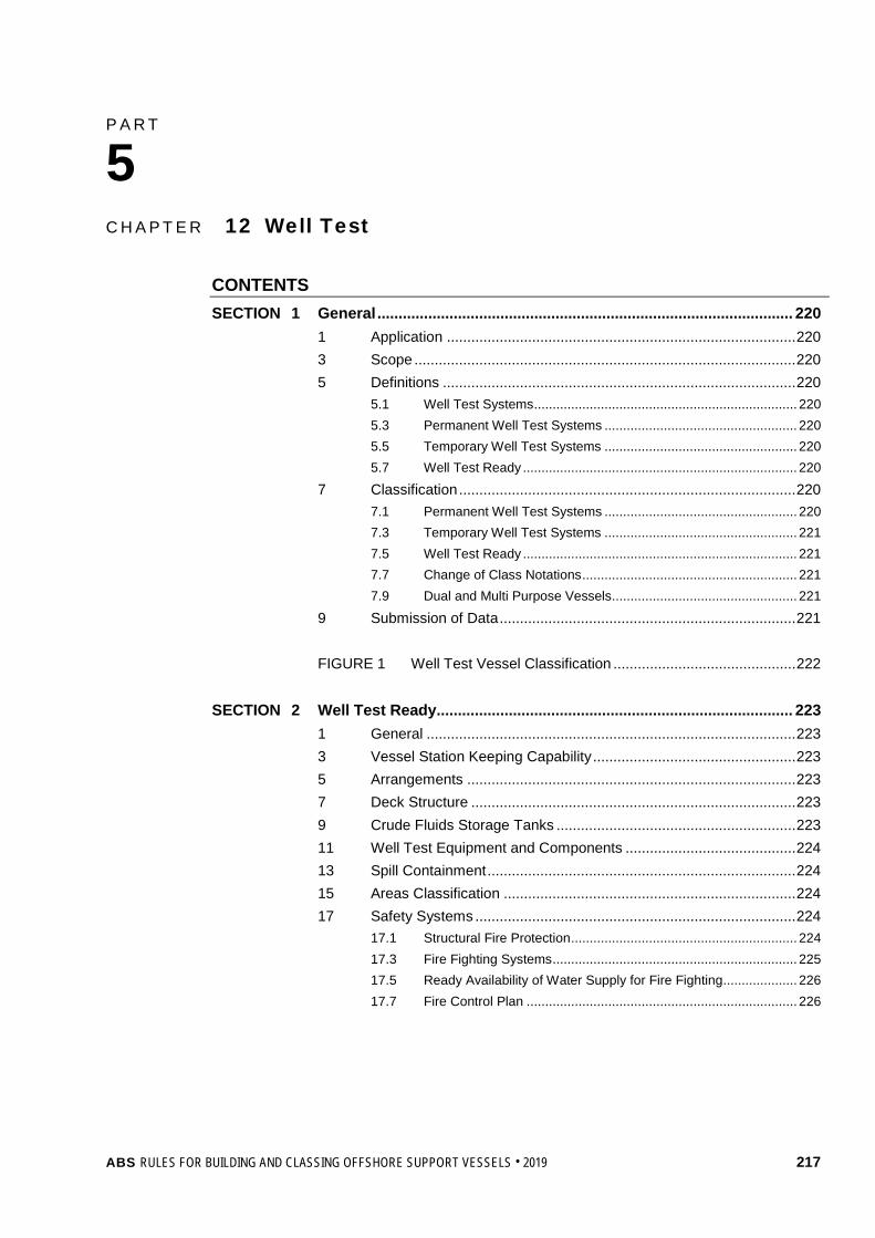
P A R T C h a p t e r 1 2 : W e l l T e s t
5 C H A P T E R 12 Well Test
CONTENTS SECTION 1 General .................................................................................................. 220
1 Application ...................................................................................... 220 3 Scope .............................................................................................. 220 5 Definitions ....................................................................................... 220
5.1 Well Test Systems ....................................................................... 220 5.3 Permanent Well Test Systems .................................................... 220 5.5 Temporary Well Test Systems .................................................... 220 5.7 Well Test Ready .......................................................................... 220
7 Classification ................................................................................... 220 7.1 Permanent Well Test Systems .................................................... 220 7.3 Temporary Well Test Systems .................................................... 221 7.5 Well Test Ready .......................................................................... 221 7.7 Change of Class Notations .......................................................... 221 7.9 Dual and Multi Purpose Vessels .................................................. 221
9 Submission of Data ......................................................................... 221 FIGURE 1 Well Test Vessel Classification ............................................. 222
SECTION 2 Well Test Ready .................................................................................... 223
1 General ........................................................................................... 223 3 Vessel Station Keeping Capability .................................................. 223 5 Arrangements ................................................................................. 223 7 Deck Structure ................................................................................ 223 9 Crude Fluids Storage Tanks ........................................................... 223 11 Well Test Equipment and Components .......................................... 224 13 Spill Containment ............................................................................ 224 15 Areas Classification ........................................................................ 224 17 Safety Systems ............................................................................... 224
17.1 Structural Fire Protection ............................................................. 224 17.3 Fire Fighting Systems .................................................................. 225 17.5 Ready Availability of Water Supply for Fire Fighting .................... 226 17.7 Fire Control Plan ......................................................................... 226
ABS RULES FOR BUILDING AND CLASSING OFFSHORE SUPPORT VESSELS . 2019 217

SECTION 3 Installation of Temporary Well Test Systems ................................... 227 1 General ........................................................................................... 227 3 Documentation Requirements ........................................................ 227 5 General Arrangement ..................................................................... 228 7 Deck Structure ................................................................................ 228 9 Crude Fluid Storage Tank ............................................................... 228 11 Well Test Equipment ....................................................................... 228
11.1 Portable Pressure Retaining Components ................................... 228 11.3 Well Control Components ............................................................ 229 11.5 Well Injection Line ........................................................................ 229 11.7 Pumps .......................................................................................... 229 11.9 Air Compressors .......................................................................... 229 11.11 Spill Containment ......................................................................... 229 11.13 Hydrocarbon Disposal Facilities ................................................... 229
13 Areas Classification ........................................................................ 229 13.1 General ........................................................................................ 229 13.3 Equipment Installations in Vicinity of Classified Areas ................. 230
15 Safety Systems ............................................................................... 230 15.1 Fire Safety ................................................................................... 230 15.3 Fire Fighting Systems .................................................................. 230 15.5 Passive Fire Protection ................................................................ 230 15.7 Safety Valve and Emergency Shutdown ...................................... 231 15.9 Monitoring .................................................................................... 231 15.11 Flammable Gas Detection ........................................................... 231 15.13 Hydrogen Sulfide Gas Detection .................................................. 231
17 Operational Procedures .................................................................. 231 SECTION 4 Permanent Well Test Systems ............................................................ 232
1 General ........................................................................................... 232 3 General Requirements .................................................................... 232
3.1 Arrangements of Well Test Equipment and Machinery ................ 232 3.3 Supporting Structure .................................................................... 232 3.5 Crude Fluids Storage Tanks ........................................................ 232
5 Well Test System ............................................................................ 232 5.1 Design Basis ................................................................................ 232 5.3 Pressure Retaining Components ................................................. 233 5.5 Well Control Components ............................................................ 233 5.7 Piping Systems ............................................................................ 233 5.9 Flexible Hoses ............................................................................. 233 5.11 Electrical Components and Installations ...................................... 233 5.13 Spill Containments ....................................................................... 233 5.15 Hydrocarbon Disposal Facilities ................................................... 233
7 Areas Classifications ....................................................................... 234 7.1 General ........................................................................................ 234 7.3 Crude Storage Tanks ................................................................... 234 7.5 Equipment Installations in vicinity of Classified Areas ................. 235
218 ABS RULES FOR BUILDING AND CLASSING OFFSHORE SUPPORT VESSELS . 2019
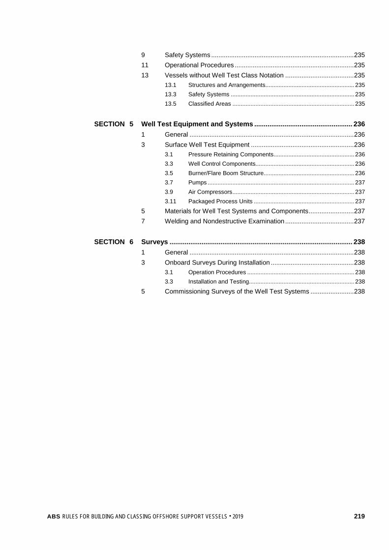
9 Safety Systems ............................................................................... 235 11 Operational Procedures .................................................................. 235 13 Vessels without Well Test Class Notation ...................................... 235
13.1 Structures and Arrangements ...................................................... 235 13.3 Safety Systems ........................................................................... 235 13.5 Classified Areas .......................................................................... 235
SECTION 5 Well Test Equipment and Systems .................................................... 236
1 General ........................................................................................... 236 3 Surface Well Test Equipment ......................................................... 236
3.1 Pressure Retaining Components ................................................. 236 3.3 Well Control Components............................................................ 236 3.5 Burner/Flare Boom Structure ....................................................... 236 3.7 Pumps ......................................................................................... 237 3.9 Air Compressors .......................................................................... 237 3.11 Packaged Process Units ............................................................. 237
5 Materials for Well Test Systems and Components ......................... 237 7 Welding and Nondestructive Examination ...................................... 237
SECTION 6 Surveys ................................................................................................. 238
1 General ........................................................................................... 238 3 Onboard Surveys During Installation .............................................. 238
3.1 Operation Procedures ................................................................. 238 3.3 Installation and Testing................................................................ 238
5 Commissioning Surveys of the Well Test Systems ........................ 238
ABS RULES FOR BUILDING AND CLASSING OFFSHORE SUPPORT VESSELS . 2019 219

P A R T S e c t i o n 1 : G e n e r a l
5 C H A P T E R 12 Well Test
S E C T I O N 1 General
1 Application The requirements in this Chapter apply to offshore support vessels equipped with well test systems and intended for unrestricted service.
3 Scope (2018) The scope of this Chapter is limited to a vessel’s structural and equipment arrangements.
5 Definitions
5.1 Well Test Systems Well test systems are the facilities installed on vessels or mobile offshore drilling units (MODUs) for the purpose of evaluating the quality and/or quantity of the well fluid to determine whether the well should be completed for production or plugged and abandoned. Well test systems may include well control equipment, process pressure vessels, piping and electrical components, control systems, burners and gas flares and burner/flare booms.
5.3 Permanent Well Test Systems (2018) Well test systems installed onboard a vessel for at least 12 months are considered permanent, notwithstanding if the system is or is not in operation.
5.5 Temporary Well Test Systems (2018) Well test systems installed on board a vessel for less than 12 months are considered temporary.
5.7 Well Test Ready Vessels that have been designed for well test operations, but the well test system has not been installed onboard, are considered “well test ready”.
7 Classification (2018) In accordance with Section 1-1-2 of the OSV Rules Supplement to the ABS Rules for Conditions of Classification (Part 1) and 5-1-1/5.1 of these Rules, the following service notations are to be assigned to vessels designed primarily for the services listed in 5-12-1/5.1 and built to the requirements of this Chapter and other relevant sections of these Rules.
7.1 Permanent Well Test Systems (2018) Vessels fitted with permanent well test systems that comply with the requirements of this Chapter will be assigned the classification À A1 Offshore Support Vessel (Well Test). Vessels with well test systems installed on board and not assigned with notation Well Test are to comply with the minimum mandatory requirements of 5-12-4/13 of these Rules. In this case, no class notation related to well testing systems will be assigned to the vessel or the unit.
220 ABS RULES FOR BUILDING AND CLASSING OFFSHORE SUPPORT VESSELS . 2019
Part 5 Specialized Services Chapter 12 Well Test Section 1 General 5-12-1
7.3 Temporary Well Test Systems (2018) Vessels with temporary well test systems are to comply with the requirements in Section 5-12-3 for maintaining classification status.
7.5 Well Test Ready (2018) Vessels designed to be “well test ready” that comply with the requirements of this Chapter will be assigned the classification À A1 Offshore Support Vessel (WT-READY).
7.7 Change of Class Notations The installation or removal of the well test systems on board vessels is to be notified to ABS in order to re-assess the compliance with the classification requirements. The class notations will be modified as necessary to reflect the new status of the vessel
7.9 Dual and Multi Purpose Vessels Vessels intended for well test operations and providing additional services may be classed with combinations of the applicable notations for the relevant service as explained in Section 5-1-1.
In such instances, the dual or multipurpose vessel is to be designed and built to these requirements, as well as to those applicable for the particular additional service or services.
9 Submission of Data (2018) In general, in addition to the plans listed in Section 1-1-4 of the OSV Rules Supplement to the ABS Rules for Conditions of Classification (Part 1), the following plans and particulars are to be submitted.
• Project Specification
• Process Flow Sheets
• General Arrangement Plan
• Equipment Layout Drawings and equipment Documentation
• Information regarding loading arrangement of deck equipment and tanks, weights and centers of gravity
• Structural details and arrangements of the structures in way of deck equipment and tanks
• Details of integral liquid tanks including venting and/or inerting
• Details of independent liquid and/or dry tanks with support and fastening arrangement
• Burner/Flare Boom Structural Drawings
• Piping and Instrument Diagrams (P & ID’s)
• Pressure Relief and Depressurization Systems
• Flare and Vent System
• Gas Dispersion and Radiant Heat Study
• Spill Containment and Drain Systems
• Electrical One-line Diagrams
• Instrumentation and Control Systems
• Fire Fighting System including
- Firewater System
- Water Spray (Deluge) Systems for Well Test Equipment
- Foam Systems for Hydrocarbon Storage Tanks
ABS RULES FOR BUILDING AND CLASSING OFFSHORE SUPPORT VESSELS . 2019 221

Part 5 Specialized Services Chapter 12 Well Test Section 1 General 5-12-1
- Portable and Semi-Portable Extinguishers
- Fire and Gas Detection and Alarm Systems
- Fire and Gas Cause and Effect Chart
• Operating Manual
For details, reference is made to Chapter 3, Section 2 of the ABS Rules for Building and Classing Facilities on Offshore Installations (Facilities Rules).
FIGURE 1 Well Test Vessel Classification (2018)
ABS ClassedVessel
READYNotation
Requested?
OSV5-12
Not Applicable
WT SystemsOnboard
≥ 12 months
no
Well Test
SystemInstalled?
yesno
Well TestNotation
Requested?
OSV5-12-4/13
no
no
yes
yes
Wel
l Tes
t Sys
tem
In
stal
latio
n
Well TestOSV
5-12-4
OSV5-12-3
WT-READYOSV
5-12-2
222 ABS RULES FOR BUILDING AND CLASSING OFFSHORE SUPPORT VESSELS . 2019
P A R T S e c t i o n 2 : W e l l T e s t R e a d y
5 C H A P T E R 12 Well Test
S E C T I O N 2 Well Test Ready (2018)
1 General In addition to the requirements for the structures, well test equipment and systems in the Well Test Guide, the provisions in this Section are applicable.
3 Vessel Station Keeping Capability Vessels are to be capable of maintaining their positions safely during well test operations.
Dynamic positioning systems, when used to maintain the vessel’s position during well test operations, are to comply with the requirements for the class notation DPS-2 or DPS-3 (see the ABS Guide for Dynamic Positioning Systems).
5 Arrangements Equipment layout and work areas associated with the well testing activities are to be arranged with the design principles given in 5-10-2/3.1. The area in which the well test processing plant will be installed is to be defined and marked on the general arrangement plan of the vessels.
7 Deck Structure i) The maximum deck loading for the well test system and its components is to be predetermined,
either by a uniformly distributed load or by localized loads, if the footprint of the deck connections is known.
ii) Deck structures that will support the well test system, when installed, are to be appropriately reinforced and analyzed based on the maximum loading conditions in compliance with the Part 3, Chapter 2, as applicable. The maximum deck loading used in the structural analysis is to be clearly reflected in the deck structural drawing.
iii) A description of the specific locations where the well testing equipment will be placed and the maximum deck loading at those locations are to be reflected in the Operating Manual (see 1-1-5/1.15 of the MODU Rules).
9 Crude Fluids Storage Tanks Storage tanks designated for storage of crude fluids for well testing operations are to comply with the applicable requirements in 5-10-2/5.3 in terms of tank locations, construction, segregation and protection, venting and piping system, dependent on the type and characteristics of the vessels.
In addition, storage tanks for hydrocarbon or other flammable liquids are to be located away from the designated wellheads and away from potential ignition sources such as gas and diesel engines, fired vessels, and buildings designated as unclassified areas, or areas used as workshops, or welding locations.
ABS RULES FOR BUILDING AND CLASSING OFFSHORE SUPPORT VESSELS . 2019 223

Part 5 Specialized Services Chapter 12 Well Test Section 2 Well Test Ready 5-12-2
11 Well Test Equipment and Components Well test equipment and components that are permanently installed on board the vessel, are to comply with Section 5-12-5 as appropriate.
Where burner/flare booms are installed on board, the boom structures are to comply with 5-12-5/3.5.
13 Spill Containment i) Spill containment is to be provided in areas which may be subject to hydrocarbon liquid or
chemical spills when the well test system is installed, such as areas around process vessels, heat exchangers and storage tanks with drain or sample connections, pumps, valves, manifolds, metering and data recording units and chemical storage and dispensing areas.
ii) Spill containment is to utilize curbing or drip edges at deck level, recessed drip pans, containment by floor gutters, firewalls or protective walls, or equivalent means to prevent spread of discharged liquids to other areas and spillover to lower levels.
iii) Where equipment is protected by a fixed foam fire extinguishing system, a minimum of 150 mm (6 in.) coaming is to be provided.
iv) Each containment area, as well as any other plated deck or skid area subject to rainwater or other liquid accumulation, is to be equipped with drains connected to an open drain system, and installed and located so as to prevent the accumulation of standing liquid.
v) Spill containment areas and open and closed drain systems that are installed on board are to comply with 3-3/17 of the Facilities Rules.
15 Areas Classification Area classification related to the installation of well test systems are to be delineated in accordance with the recommended practice of API RP 500 or API RP 505. The provisions of 5-10-2/5.11 are applicable as appropriate.
17 Safety Systems i) Safety systems that are installed permanently on board vessel are to comply with 5-12-4/9.
ii) Adequate provision is to be made in the following onboard systems for the future connection and operation of the well test safety systems:
• Monitoring and alarm systems
• Gas detection systems
• Water spray system
17.1 Structural Fire Protection 17.1.1 Fire Integrity of Exterior Bulkheads
For superstructures and deck houses enclosing accommodation and machinery spaces, the following areas are to be of steel construction and insulated to “A-60” standard:
i) The exterior bulkheads facing the designated process areas containing wellheads/well fluid reception facilities, oil storage tanks, fired vessels, crude oil process vessels and other similar hazards;
ii) The side bulkheads within a distance of 3 m (10 ft) from the end bulkhead facing the designated process areas.
224 ABS RULES FOR BUILDING AND CLASSING OFFSHORE SUPPORT VESSELS . 2019
Part 5 Specialized Services Chapter 12 Well Test Section 2 Well Test Ready 5-12-2
Insulation to “A-0” standard may be acceptable provided the bulkheads are protected by a fixed water-spray (water curtain) system with a minimum water capacity of 10 liters/minute/m2 (0.25 gpm/ft2) in accordance with 5-4-3/9.
Access doors are to meet the same requirements as the bulkhead.
Reference is made to 5-12-3/15.5.1 and 5-12-4/9 for additional passive fire protection requirements for temporary well test system installation and Well Test notations, respectively.
17.1.2 Opening in Exterior Bulkheads Access doors, air inlets and openings to accommodation spaces, service spaces, control stations and machinery spaces are not to face the designated areas for well test processing plants. They are to be located on the outboard side of the superstructure or deckhouse at a distance of at least 3 meters (10 ft) from the end of the superstructure or deck house facing the well test processing area with the exception of the following:
i) Access doors, air inlets and openings to accommodation spaces, service spaces, control stations and machinery spaces may face the well test processing area and/or be located within the above limits provided they are located at least one deck above the well test processing area and are at least 3 meters (10 feet) measured horizontally away from a vertical plane of the storage oil tanks and sources of oil or vapor release.
ii) Access doors located on the well test processing deck to accommodation spaces, service spaces, control stations and machinery spaces may face the well test processing area and/or be located within the above limits provided the requirements in 5-6-4/11.7 are met as appropriate.
iii) Navigation bridge doors and windows may face the well test processing area and/or be located within the above limits provided they are capable of being made gastight during well test operation.
iv) Portlights and windows fitted in locations other than the navigation bridge may face the well test processing area and/or be located within the above limits provided they are of the fixed (non-opening) type. They are to be fitted with deadlights constructed of steel or other equivalent material, which must be secured during well test operations.
v) Bolted plates for the removal of machinery may face the cargo area and/or be fitted within the above limits.
17.3 Fire Fighting Systems 17.3.1 Fire Hoses and Nozzles
Firewater stations and their arrangements are to provide at least two jets of water not emanating from the same fire station to reach any part of the well test system that may be exposed to fire. Fire hoses and nozzles are to comply with the requirements of 4-7-3/1.13 and 4-7-3/1.15.
17.3.2 Foam Systems i) Deck foam systems are to be provided for vessel storing crude fluids in integral storage
tanks in accordance with 5C-1-7/27 of the Steel Vessel Rules. In addition, the storage tanks to be installed on deck in the future are to be taken into account of deck foam system design.
ii) When the total capacity of the crude storage tanks is not greater than 800 m3 (28250 ft3), a fixed dry chemical fire-extinguishing system may be installed in lieu of the deck foam system, provided that the following conditions are complied with:
• On a deck area of 45 m2 (484 ft2) or less, there are two or more dry chemical extinguishers with total capacity is not less than 135 kg (300 lbs);
ABS RULES FOR BUILDING AND CLASSING OFFSHORE SUPPORT VESSELS . 2019 225

Part 5 Specialized Services Chapter 12 Well Test Section 2 Well Test Ready 5-12-2
• On a deck area of more than 45 m2 (484 ft2), there are three or more dry chemical extinguishers with total capacity is not less than:
C = 3A kg
C = 0.62A lbs
Where A is the deck area in m2 (ft2).
Where a fixed dry chemical fire-extinguishing system is installed, the minimum rate of supply of the extinguishing agent is not less than 3 kg/min/m2 (0.62 lbs/min/ft2)
17.5 Ready Availability of Water Supply for Fire Fighting i) Where the water spray (deluge) systems, and/or the deck foam systems for chemical storage tanks
and process equipment are intended to have water supply from the fire main systems, the fire pumps and the associated piping systems are to be capable of supplying the maximum probable demand for operating these systems on board.
ii) Well test area is to be within the coverage of a fixed water spray system with a water application rate not less than 20.4 L/min/m2 (0.5 gpm/ft2) or at least two dual-purpose (jet/spray) fire monitors, each with minimum capacity not less than 100m3/h (440 gpm), refer to 3-8/5.1.4 of the Facilities Rules.
17.7 Fire Control Plan Separate fire control plans may be developed for the anticipated temporary well test equipment installation and submitted to ABS for review. The pre-approved fire control plans are to be kept onboard for use when temporary well test equipment is installed.
226 ABS RULES FOR BUILDING AND CLASSING OFFSHORE SUPPORT VESSELS . 2019

P A R T S e c t i o n 3 : I n s t a l l a t i o n o f T e m p o r a r y W e l l T e s t S y s t e m s
5 C H A P T E R 12 Well Test
S E C T I O N 3 Installation of Temporary Well Test Systems
1 General For vessels to be fitted with well test equipment and system for temporary operations, the arrangements and installations of the temporary equipment on board are to comply with the provisions in this Section for maintaining classification status.
For vessels having been assigned with WT-READY notation, the equipment installations and system integrations are to meet the minimum requirements outlined in this section.
For vessels without WT-READY notation assigned, the vessels are to comply with the requirements in Section 5-12-2. In addition, the equipment installation and system integrations are to comply with the provisions given in this Section.
3 Documentation Requirements Plans showing the arrangement, details, and interface of the well test equipment on board the host vessel are to be submitted and approved prior to installation of those temporary well test equipment. Where these plans have been pre-approved, onboard provision can be verified by the attending Surveyor. When minor changes are necessary, the Surveyor may verify the updated plans, endorse them to signify the correctness, and the vessel may use these plans temporarily.
In general, these plans should include the following:
i) General arrangement plans of the vessel showing the proposed location of each temporary equipment onboard the vessel
ii) Hazardous area plans showing the host vessel’s updated area classifications due to installation of the proposed temporary equipment and the equipment certification demonstrating its suitability to the intended hazardous area classification
iii) Drawings showing the securing details and arrangements along with supporting calculations; if equipment modules are stacked, full details are to be submitted
iv) Drawings showing scantlings and details for the supporting deck structure on which the equipment is to be installed
v) Updated fire control plans for the vessel
vi) Details showing the integration with the host vessel’s piping, electrical systems, including power supply, control, monitoring, alarm, and communications systems, where applicable
vii) Host vessel’s load analysis to demonstrate that sufficient power is available such that any additional power required by the well test facilities does not adversely affect the safety of the host vessel
viii) Updated stability information to account for additional weight
ix) Details of additional lifesaving appliance where ABS is issuing statutory certificates on behalf of the flag Administration
x) Updated operation manual including well intervention equipment and systems
ABS RULES FOR BUILDING AND CLASSING OFFSHORE SUPPORT VESSELS . 2019 227
Part 5 Offshore Support Vessels for Specialized Services Chapter 12 Well Test Section 3 Installation of Temporary Well Test Systems 5-12-3
5 General Arrangement Machinery and equipment are to be located in the predefined working areas and arranged in groups for safe operation, easy access for inspection and maintenance, and adequate escape route for emergency evacuation.
7 Deck Structure i) Well test equipment is to be securely attached to the hull structure of the vessel using suitable
means of fastening such as welding or bolting in accordance with the approved securing manual, see 5-12-3/3iii). Due consideration is to be given such that equipment operation, emergency response, and personnel escape are not to be adversely affected by fastening arrangements.
ii) Deck foundations and fastening arrangements are to permit relative movement of pressure vessels and large gas storage cylinders due to internal pressure variations that may cause them to expand or contract.
9 Crude Fluid Storage Tank i) Temporary storage tanks on deck for receipt of well fluids or other flammable liquids are to be
located as far as possible from wellheads, potential ignition sources such as gas and diesel engines, fired vessels, buildings designated as unclassified areas, areas used as workshops, or welding locations.
ii) Precautions are to be made for prevention or protection against falling objects on the tanks.
iii) Tanks are to be securely fastened on deck, refer to 5-10-3/3.3ii).
iv) Where pressure/vacuum relief valves are fitted, pressure relief lines are to be connected to the low-pressure flare headers (less than 2.5 psig or 0.17 kg/cm2), or discharged at a location with a height of not less than 2 m (6.5 ft) above the weather deck and a distance of not less than 10 m (33 ft) measured horizontally from the nearest air intake or opening to accommodation, service, and machinery spaces and source of ignition.
v) Free flow vents are to be fitted with flame arresters.
11 Well Test Equipment
11.1 Portable Pressure Retaining Components i) Portable pressure retaining components or pressure vessels are to have valid certification showing
they are designed, manufactured, and inspected in accordance with the ASME “Boiler and Pressure Vessel Code Section VIII Division 1 or Division 2” or other recognized standards.
ii) At least two relief valves or the equivalent devices are to be provided on test separators. The relief valve vent lines are to be led outboard at least 120 pipe diameters or connected to a suitable hydrocarbon disposal facility. Any vent line valves are to be interlocked to provide one open flow path for all vents at any time.
iii) All pressurized vessels in the well test process system are to be capable of being blown down from a safe location.
iv) Each individual component in the process plant downstream the choke manifold is to be arranged for possible being bypassed.
v) Vessels design for, or potentially operated as, atmospheric vessels are to be equipped with devices to or designed to prevent return of air or backfire to occur.
228 ABS RULES FOR BUILDING AND CLASSING OFFSHORE SUPPORT VESSELS . 2019

Part 5 Offshore Support Vessels for Specialized Services Chapter 12 Well Test Section 3 Installation of Temporary Well Test Systems 5-12-3
11.3 Well Control Components Well control components such as flowheads, test trees, choke manifold, and emergency shutdown valves (ESDV) are to have valid certification showing they are designed and fabricated in accordance with recognized standards such as API Spec 6A, API Spec 16C, API Spec 6D, API Spec 16D and API Spec 6AV1.
11.5 Well Injection Line Each well injection line is to be provided with a double non-return valve located at a flowhead or test tree.
11.7 Pumps Pumps intended for hydrocarbon services are to have affidavit from the manufacturer confirming compliance with API Std. 610 or other applicable recognized standard.
11.9 Air Compressors Where installed in well test area, air compressors are to be suitable for operation in Zone 2 area, and to be equipped with automatic shutdown device in case of exposure to hydrocarbon gases.
11.11 Spill Containment Spill containment are to be provided in areas around process vessels, and storage tanks with drain or sample connections, pumps, valves, manifolds, metering and data recording units and chemical storage and dispensing areas.
Where equipment is protected by a fixed foam fire extinguishing system, a minimum of 150 mm (6 in.) coaming is to be provided.
Each containment area, as well as any other plated deck or skid area subject to rainwater or other liquid accumulation, is to be equipped with drains connected to an open drain system, and installed and located so as to prevent the accumulation of standing liquid.
11.13 Hydrocarbon Disposal Facilities The burner/flare boom structures complying with 5-12-5/3.5 of these Rules are to be secured on the hull structure in accordance with the approved manual, see 5-12-3/3iii).
Two flare lines are to be provided at opposite sides of the vessel or unit. Single flare line will be specially considered for vessels fitted with dynamic positioning (DP) systems and with respect to the arrangements made to limit exposure of personnel, equipment, and helicopter traffic to vented gas, flare exhaust, or flame radiation.
Flare burners are to be so located to minimize the radiant heat intensity from flaring at the unit where normal maintenance or operating activity could take place.
Cooling arrangements for flare burner and heat shields (water curtain) are to be available.
13 Areas Classification
13.1 General i) Pre-approved hazardous areas plans are to be revalidated for temporary equipment installation.
ii) The area that includes the equipment and extends 3 m from the equipment’s perimeter is regarded as Zone 2. See also 4-3-6/6.9 of the MODU Rules.
iii) Electrical equipment installed within classified areas is to be certified type and suitable for the hazardous area where installed. As needed, de-energization of such an electrical equipment is to be in accordance with operator’s safety de-energization protocol.
ABS RULES FOR BUILDING AND CLASSING OFFSHORE SUPPORT VESSELS . 2019 229

Part 5 Offshore Support Vessels for Specialized Services Chapter 12 Well Test Section 3 Installation of Temporary Well Test Systems 5-12-3
13.3 Equipment Installations in Vicinity of Classified Areas 13.3.1 Electrical Equipment
All equipment in exterior locations which is capable of operation or remains electrically energized after shutdown on gas detection is to be suitable for installation in Zone 2 locations.
13.3.2 Fired Heaters, Internal Combustion Engines and Hot surfaces i) Fired heaters and internal combustion engines are to have air intakes located at least 3 m
(10 ft) from any classified area.
ii) Exhaust outlets of fired heaters and internal combustion engines are to discharge outside of all classified areas.
iii) Exhaust outlets of internal combustion engines are to be equipped with spark arresting devices.
iv) Hot surfaces that may constitute a source ignition of flammable vapor are to be protected by insulation, cooling, use of gas tight enclosure, etc.
v) Automatic air intake shut-off valves or equivalent safety devices are to be provided in internal combustion engines when the air intake is located at less than 15 m (50 ft) from any point where an abnormal release of large amount of flammable gas may occur.
vi) Power package in working areas is to be certified for operating in Zone 2 area.
15 Safety Systems
15.1 Fire Safety i) Onboard provision of a pre-approved fire control plans is to be verified.
ii) All newly added fire and safety features are to be certified, installed, and tested in accordance with the Rules or recognized standards to the satisfaction of the attending Surveyor.
iii) Safety systems and appliances in the work area are to be adequately protected or located such that they will not be exposed to excessive fire loads.
iv) All electrical cables for safety systems are to be fire resistant or suitably protected, see 4-3-3/5.15 and 4-3-3/5.17 of the MODU Rules.
15.3 Fire Fighting Systems i) Water spray system or fire monitors system in accordance with 5-12-2/17.5ii) for well test area is
to be installed and tested. The monitors may be operated either remotely or locally. Monitors arranged for local operation are to be sited on an accessible protected position.
ii) Fire hoses and nozzles in compliance with 5-12-2/17.3.1 are to be provided.
iii) Portable fire extinguishers are to be provided in the well test working areas in accordance with the requirements 5-2-4/1 of the MODU Rules.
15.5 Passive Fire Protection 15.5.1 General
“H-60” ratings are required for all bulkheads and decks requiring structural fire protection specified in 5-12-2/5.1.4. “A-60” and “A” rated bulkheads may be utilized provided either one condition below is met:
i) “A-0” fire walls are provided in front of the protected areas
ii) A risk or fire load analysis was performed and reviewed by ABS, indicating that these bulkheads are acceptable
230 ABS RULES FOR BUILDING AND CLASSING OFFSHORE SUPPORT VESSELS . 2019

Part 5 Offshore Support Vessels for Specialized Services Chapter 12 Well Test Section 3 Installation of Temporary Well Test Systems 5-12-3
15.5.2 Process Machinery and Equipment Installations 15.5.2(a) Wellhead Areas or Well Fluid Reception Facilities. Wellhead areas or well fluid reception facilities are to be separated or protected from sources of ignition and mechanical damage. A-0 firewalls around wellheads are to be used to provide protection from potential uncontrolled flow from wellheads with shut-in pressure exceeding 42 kg/cm2 (600 psig).
15.5.2(b) Fired Vessels. Fired vessels are to be installed away from wellheads and other unfired hydrocarbon processing and storage equipment. Where this arrangement is not practicable, the fire vessel is to be surrounded on all sides by a minimum of A-0 rated firewall.
15.7 Safety Valve and Emergency Shutdown i) A safety valve fitted emergence shutdown is to be provided in the flowhead line to isolate the test
facilities from the well or from well fluid storage unit.
ii) Manual activation of emergency shutdown system is to be possible both locally and at the remote control station.
iii) Communication and coordination between the unit shutdown system and the well test plant shutdown system are to be arranged.
iv) Hard-wired means of communication between the DP control stations and the well test control station is to be provided.
15.9 Monitoring The process system flow rate, pressure, level, and temperature are to be automatically monitored and controlled, and the abnormal conditions are to be alarmed with visual and audible devices.
15.11 Flammable Gas Detection Gas detection is to be provided in well test areas. Visual and audible alarms are to be set at 20% and 60% (LEL) lower explosive limit. Process safety shutdown functions are to be initiated upon high gas detection.
15.13 Hydrogen Sulfide Gas Detection Hydrogen sulfide gas detection is to be provided. Visual and audible alarms are to be set at 10 ppm and 50 ppm H2S. Process safety shutdown functions are to be initiated upon high gas detection.
17 Operational Procedures Approved operational procedures are to be available on board and are to include, but not limited to, the following:
i) Production test plan for well testing
ii) Manning requirements
iii) Well test facility operations and testing procedures
iv) Process startup and shutdown procedures
v) Fire-fighting procedures
vi) Emergency evacuation procedures
ABS RULES FOR BUILDING AND CLASSING OFFSHORE SUPPORT VESSELS . 2019 231

P A R T S e c t i o n 4 : P e r m a n e n t W e l l T e s t S y s t e m s
5 C H A P T E R 12 Well Test
S E C T I O N 4 Permanent Well Test Systems
1 General Vessels fitted with permanent well test systems, as defined in 5-12-1/5.3, are to comply with the Facilities Rules and the requirements in this Section when the class notation Well Test has been requested by the Owner.
When well test systems are fitted, but the class notation Well Test is not requested, as a minimum, the system is to comply with 5-12-4/13.
3 General Requirements In addition to the general requirements for station keeping capability in 5-12-2/3, the following provisions are applicable for vessels fitted with permanent well test systems.
3.1 Arrangements of Well Test Equipment and Machinery The design principles and objectives as stated in 5-10-2/3.1 of these Rules are to be followed. The detailed machinery and equipment arrangements plans are to comply with 3-3/5 of the Facilities Rules.
3.3 Supporting Structure i) The deck supporting structures are to be built in accordance with the provisions in 5-12-2/7 and 5-
12-3/7.
ii) Where equipment is integrated in hull structure, the provisions of 5-10-4/5.3iii) are applicable.
3.5 Crude Fluids Storage Tanks i) Integral hull tanks designated for crude fluid storage are to comply with the requirements given in
5-10-2/5.3 and 5-12-2/9.
ii) Independent tanks installed on deck are to comply with the requirements in 5-10-2/3.9iii) and 5-10-4/5.5.2.
5 Well Test System
5.1 Design Basis Well test process design is to comply with the provisions of 3-3/3 of the Facilities Rules. Process flow sheets are to be provided to indicate all process equipment with associated piping system, and define operating conditions for each component.
Well test equipment certification is to be in accordance with Section 5-12-5.
232 ABS RULES FOR BUILDING AND CLASSING OFFSHORE SUPPORT VESSELS . 2019

Part 5 Offshore Support Vessels for Specialized Services Chapter 12 Well Test Section 4 Permanent Well Test Systems 5-12-4
5.3 Pressure Retaining Components i) Pressure retaining components or pressure vessels such as separators, heaters, treaters, nitrogen
storage, surge and transfer tanks, are to be certified in accordance with 5-12-5/3.1.
ii) At least two relief valves or the equivalent devices are to be provided on test separators. Each individual device is to be capable of discharging the design production rate in case of over pressure. The relief valve vent lines are to be led outboard at least 120 pipe diameters or connected to a suitable hydrocarbon disposal facility in accordance with 5-12-4/5.19. Any vent line valves are to be interlocked to provide one open flow path for all vents at any time.
iii) All pressurized vessels in the well test process system are to be capable of being blown down from a safe location.
iv) Each individual component in the process plant downstream the choke manifold is to be arranged for possible being bypassed.
v) Vessels design for, or potentially operated as atmospheric vessels are to be equipped with devices or designed to prevent return of air or backfire to occur
vi) List and rolling effects of vessels are to be taken into account for design of separator and associated control system where relevant.
5.5 Well Control Components Well control components such as flowheads, test trees, choke manifold, and emergency shutdown valves (ESDV) are to be certified in accordance with 5-12-5/3.3.
5.7 Piping Systems i) Piping systems are to be designed, fabricated and tested in accordance with 3-3/11.1, 3-3/11.3,
3-3/11.5 and 3-3/11.9 of the ABS Facilities Rules.
ii) The provisions in Sections 5, 6, and 7 of the ABS CDS Guide are to be complied with for the applicable systems.
iii) Where two sections of piping with different pressure/temperature ratings are connected, the lower rated pipe is to be protected against overpressure. Where multiple valves are used (e.g., in a double block and bleed arrangement), all of the valves are to be rated for the more severe condition.
iv) Each well injection line is to be provided with a double non-return valve located at a flowhead or test tree.
5.9 Flexible Hoses i) Flexible hoses are to be designed and constructed in accordance with 5/3.7 of the CDS Guide.
ii) Flexible hoses in the systems handling hydrocarbon are to comply with 3-3/11.7 of the Facilities Rules.
5.11 Electrical Components and Installations Electrical components are to be certified for use for their intended service. Electrical installations are to be in accordance with Chapter 3, Section 6 of the Facilities Rules.
5.13 Spill Containments Spill containments are to be arranged in accordance with 5-12-2/13 of these Rules as appropriate.
5.15 Hydrocarbon Disposal Facilities Hydrocarbon disposal facilities are to be designed in accordance with the principles of API STD 521. The following specific requirements are applicable.
ABS RULES FOR BUILDING AND CLASSING OFFSHORE SUPPORT VESSELS . 2019 233

Part 5 Offshore Support Vessels for Specialized Services Chapter 12 Well Test Section 4 Permanent Well Test Systems 5-12-4
5.15.1 General i) Hydrocarbon disposal facilities are to be of adequate capacity and construction for the
intended flow stream composition and duration of test.
ii) As a minimum, two flare lines are to be provided at opposite sides of the vessel. For vessel fitted with dynamic positioning systems, one flare line may be accepted when the vessel will not interference with other facilities during well test operations.
5.15.2 Flares and Burner Booms Flares and burner booms are to be arranged such that the incident heat (short duration) on critical surfaces does not exceed 4.73 kW/m2 (1,500 BTU/hr/ft2) (including solar radiation). The use of heat shields and water spray cooling system (water curtain) will be specially considered.
5.15.3 Burning of Atomized Crude Oil In cases where crude oil is burned and atomization is used, atomization medium supply lines are to be provided with a non-return valve or some other approved means of preventing backflow of hydrocarbons into non-hazardous piping systems.
5.15.4 Gas Flare Tip Flow Rate Gas flare tip flow rate is generally not to exceed 0.5 Mach. (see API STD 521).
7 Areas Classifications
7.1 General Classified areas related to the installation of well test systems are to be delineated in accordance with 3-6/15 of the Facilities Rules and 5-12-4/7.3 of these Rules.
7.3 Crude Storage Tanks i) Delineation of classified areas for vessels related to storage tanks for liquids with a flash point not
exceeding 60°C (140°F) is to comply with Section 4-3-6 of the MODU Rules.
ii) Vessels having crude storage tanks integral with the hull structure need not comply with 4-6-6/1.5 of the Under 90m Rules with regard to the classification of hazardous areas related to crude storage, provided they comply with the applicable requirements in the following Subparagraphs.
7.3.1 Open Decks Over Crude Storage Tanks Freely ventilated, open and gas tight deck spaces to the full breadth of the ship and 3 m (10 ft) fore and aft of cargo block to a height of 2.4 m (8 ft), or to the height of the production deck, are to be considered Class I, Division 2 areas (Zone 2).
7.3.2 Enclosed Spaces Adjacent to Crude Storage Tanks Semi-enclosed or enclosed spaces immediately adjacent to crude oil storage tanks are to be considered Class I, Division 1 areas (Zone 1).
7.3.3 Pump Rooms A continuously ventilated (20 air changes per hour) crude oil pump room is to be considered a Class I, Division 1 (Zone 1) area, provided the failure of ventilation is alarmed in a manned location.
7.3.4 Cofferdam Spaces that are separated by a single bulkhead from crude oil storage tanks are to be considered Class I, Division 1 (Zone 1) areas.
7.3.5 Crude Storage Tank Vents Areas of unrestricted ventilation around cargo tank vents are to be considered Class I Division 1 (Zone 1) areas with a spherical radius of 3 m (10 ft), and Class I Division 2 (Zone 2) for an additional 7 m (23 ft).
234 ABS RULES FOR BUILDING AND CLASSING OFFSHORE SUPPORT VESSELS . 2019
Part 5 Offshore Support Vessels for Specialized Services Chapter 12 Well Test Section 4 Permanent Well Test Systems 5-12-4
7.5 Equipment Installations in vicinity of Classified Areas Equipment installations in vicinity of classified areas are to comply with the provisions in 5-12-3/13.3.
9 Safety Systems Safety systems are to comply with 3-3/13, 3-8/5.1.3, 3-8/5.1.4, 3-8/5.1.5, 3-8/7.3, and 3-8/9 of the Facilities Rules and 5-12-3/15 of these Rules.
Where well fluid is not received on the installation directly from the well, means are to be provided to detect the actuation of ESD system, which will enable all subsea valves to shut-in.
11 Operational Procedures Operational procedures are to be submitted for ABS review and are to include, but not limited to, the following:
i) Production test plan for well testing
ii) Manning requirements
iii) Well test facility operations and testing procedures
iv) Process startup and shutdown procedures
v) Fire-fighting procedures
vi) Emergency evacuation procedures
13 Vessels without Well Test Class Notation When the class notation Well Test has not been requested by the Owner, vessels fitted with well test systems are to comply with the following minimum requirements:
13.1 Structures and Arrangements The requirements in 5-12-4/3.3 and 5-12-4/3.5 are to be complied with.
13.3 Safety Systems The safety systems are to comply with 5-12-4/9.
13.5 Classified Areas Classified areas related to the installation of well test systems are to be delineated in accordance with 5-12-4/7. Electrical components located in classified areas are to be of a type suitable for such locations.
ABS RULES FOR BUILDING AND CLASSING OFFSHORE SUPPORT VESSELS . 2019 235

P A R T S e c t i o n 5 : W e l l T e s t E q u i p m e n t a n d S y s t e m s
5 C H A P T E R 12 Well Test
S E C T I O N 5 Well Test Equipment and Systems
1 General This Section defines the equipment certification requirements for vessels with Well Test notation.
3 Surface Well Test Equipment The surface well test systems may include well control equipment, process pressure vessels, piping and electrical components, control systems, burners and gas flares, and burner/flare booms.
3.1 Pressure Retaining Components i) Pressure retaining components or pressure vessels are to be designed, manufactured, and inspected in
accordance with the ASME “Boiler and Pressure Vessel Code Section VIII Division 1 or Division 2” or other recognized standards.
ii) Oil/gas separators are to comply with the requirements of API Spec 12J.
iii) List and rolling effects of floating type units are to be taken into account for design of separator and associated control system where relevant.
3.3 Well Control Components Well control components such as flowheads, test trees, choke manifold, and emergency shutdown valves are to be designed, fabricated, and tested in accordance with recognized standards such as API Spec 6A, API Spec 16C, API Spec 6D, API Spec 16D and API Spec 6AV for the intended pressure and temperature, see 5-12-4/5.3.
3.5 Burner/Flare Boom Structure The burner/flare boom structures are to be designed and constructed in accordance with API RP 2A for secondary structures and the following subsections.
3.5.1 Design Loads The loads to be considered in the design of a boom structure include, as appropriate:
i) Dead weight of structure, piping, fittings, rigging, snow and ice, walkways, guard rails, etc.
ii) Wind Loads
iii) Thermal and impulsive loads resulting from the use of the flare
iv) Vessel motion-induced loads
The values of all design loads are to be listed in the submitted design documentation. Loads resulting from vessel motions and wind loads can be established using the procedures given in the API Spec 4F. The derivation of loading conditions to be used in the design is to give due account of the operational requirements of the user, and should reflect both the operational and stowed modes of the boom.
For local loads of walkways and platforms associated with the boom, reference is made to 3-1-3/1.11.3 of the MODU Rules.
236 ABS RULES FOR BUILDING AND CLASSING OFFSHORE SUPPORT VESSELS . 2019

Part 5 Offshore Support Vessels for Specialized Services Chapter 12 Well Test Section 5 Well Test Equipment and Systems 5-12-5
3.5.2 Allowable Stresses Reference is to be made to the AISC or other recognized standard for limits on stress to preclude excessive stresses in members and connections or buckling. Permission to use a one-third increase in allowable stress must be specially approved by ABS.
3.7 Pumps Pumps intended for hydrocarbon services are to comply with API Std. 610 or other applicable recognized standard.
3.9 Air Compressors Where installed in well test area, air compressors are to be suitable for operation in zone 2 area, and to be equipped with automatic shutdown device in case of exposure to hydrocarbon gases.
3.11 Packaged Process Units Packaged process units, where fitted, are to comply with 3-3/7 of the Facilities Rules.
5 Materials for Well Test Systems and Components Materials for well test systems and components are to comply with the applicable provisions in Chapter 5 of the CDS Guide.
7 Welding and Nondestructive Examination Welding and nondestructive examination (NDE) are to be qualified and performed in accordance with the equipment or components design codes and standards. The provisions in Chapter 6 of the CDS Guide are applicable.
ABS RULES FOR BUILDING AND CLASSING OFFSHORE SUPPORT VESSELS . 2019 237

P A R T S e c t i o n 6 : S u r v e y s
5 C H A P T E R 12 Well Test
S E C T I O N 6 Surveys
1 General This Section pertains to surveys of well test system installation onboard the vessels prior to commencement of well intervention operations. The survey and testing requirements for well test system components at the vendor’s plant of manufacture are contained in the CDS Guide and the relevant recognized standards.
3 Onboard Surveys During Installation
3.1 Operation Procedures Operation procedures are to detail the well test plan. Manning requirements, equipment operations, and emergency procedures are to encompass component testing, well test startup and shutdown, fire fighting procedures, and emergency evacuation.
3.3 Installation and Testing Installation and testing of well test equipment is to be witnessed by an ABS Surveyor for the initial installation of the test equipment. Subsequent installation of an identical arrangement may be witnessed to the extent deemed necessary by the attending Surveyor.
5 Commissioning Surveys of the Well Test Systems Commissioning of well test systems is to be verified by an attending ABS Surveyor and is to be in accordance with ABS agreed test procedures.
238 ABS RULES FOR BUILDING AND CLASSING OFFSHORE SUPPORT VESSELS . 2019
P A R T C h a p t e r 1 3 : E s c o r t
5 C H A P T E R 13 Escort
CONTENTS SECTION 1 General .................................................................................................. 241
1 Application ...................................................................................... 241 3 Classification ................................................................................... 241 5 Record Entries ................................................................................ 241
5.1 Bollard Pull .................................................................................. 241 5.3 Quasi-Steady Pull ........................................................................ 241 5.5 Quick Release ............................................................................. 241
SECTION 2 Plans and Data ..................................................................................... 242
1 Hull and Machinery Plans ............................................................... 242 3 Stability Guidance for the Master .................................................... 242 5 Bollard Pull ...................................................................................... 242 7 Quasi-Steady Pull ........................................................................... 242
SECTION 3 Definitions ............................................................................................. 243
1 Quasi-Steady Pull ........................................................................... 243 3 Static Bollard Pull ............................................................................ 244 5 Direct Towing Mode ........................................................................ 244 7 Indirect Towing Mode ...................................................................... 244 FIGURE 1 Quasi-Steady Towline Forces ............................................... 243
SECTION 4 Intact Stability ....................................................................................... 245
1 General ........................................................................................... 245 3 Propulsion ....................................................................................... 245 5 Intact Stability Criteria ..................................................................... 245 7 Heeling Arm for Escort Operation ................................................... 246 9 Stability Analysis Requirements ..................................................... 247 FIGURE 1 Righting Arm and Heeling Arm Curves with Areas A, B, C
and D ..................................................................................... 246 FIGURE 2 Escort Tug Equilibrium Position ............................................ 247
ABS RULES FOR BUILDING AND CLASSING OFFSHORE SUPPORT VESSELS . 2019 239

SECTION 5 Towing Gear .......................................................................................... 248 1 Arrangement ................................................................................... 248 3 Safety Measures ............................................................................. 248
3.1 Quick Release Device.................................................................. 248 3.3 Weak Link .................................................................................... 248
5 Strength ........................................................................................... 248 5.1 Towline ........................................................................................ 248 5.3 Towing Hook, Towing Winch, Towing Bollard and Towing
Bitts .............................................................................................. 248 5.5 Supporting Structure .................................................................... 249 5.7 Connections ................................................................................. 249
SECTION 6 Vessel Design ....................................................................................... 250
1 Hull Design ...................................................................................... 250 3 Side Structures................................................................................ 250 5 After Deck ....................................................................................... 250 7 Weather Deck Openings ................................................................. 250 9 Line Handling Equipment ................................................................ 250 11 Fendering ........................................................................................ 250 13 Equipment ....................................................................................... 250
SECTION 7 Verification of Steering Capability ...................................................... 251
1 Full Scale Testing Requirements .................................................... 251 3 Computer Model Simulation Requirements .................................... 251
3.1 General ........................................................................................ 251 3.3 Steering Capability ....................................................................... 251 3.5 Computer Model Simulation ......................................................... 251 3.7 Conventional Vessels with Rudder .............................................. 252
SECTION 8 Tests and Surveys ................................................................................ 253
1 Static Bollard Pull Test .................................................................... 253 3 Quick Release Test ......................................................................... 253 5 Surveys ........................................................................................... 253 7 Winch Test ...................................................................................... 253
240 ABS RULES FOR BUILDING AND CLASSING OFFSHORE SUPPORT VESSELS . 2019

P A R T S e c t i o n 1 : G e n e r a l
5 C H A P T E R 13 Escort
S E C T I O N 1 General
1 Application The requirements in this Chapter apply to Offshore Support Vessels which are intended for escort service (i.e., accompanying another vessel in transit). Escort vessels are intended to provide assistance to disabled vessels in emergencies involving impaired maneuverability due to loss of propulsion or steering or both.
3 Classification In accordance with Section 1-1-2 of the OSV Rules Supplement to the ABS Rules for Conditions of Classification (Part 1) and 5-1-1/5.1 of these Rules, the classification of À A1 Offshore Support Vessel (Escort) is to be assigned to vessels designed and built to the requirements of this Chapter and other relevant sections of these Rules.
Vessels intended for escort operations and providing additional services may be classed with combinations of the applicable notations for the relevant service as explained in Section 5-1-1.
In such instances, the dual or multipurpose vessel is to be designed and built to these requirements, as well as to those applicable for the particular additional service or services.
5 Record Entries
5.1 Bollard Pull The static bollard pull, as determined by 5-13-2/5, will be indicated in the Record.
5.3 Quasi-Steady Pull The quasi-steady pull, as determined by 5-13-2/7, will be indicated in the Record.
5.5 Quick Release The letters QR will be entered in the Record to indicate a remote control quick release device is provided in accordance with 5-13-5/3.
ABS RULES FOR BUILDING AND CLASSING OFFSHORE SUPPORT VESSELS . 2019 241

P A R T S e c t i o n 2 : P l a n s a n d D a t a
5 C H A P T E R 13 Escort
S E C T I O N 2 Plans and Data
1 Hull and Machinery Plans In general, in addition to the plans required to be submitted by Section 1-1-4 of the OSV Rules Supplement to the ABS Rules for Conditions of Classification (Part 1), the following additional plans are to be submitted in the same manner.
• Structural details and arrangements of the structures in way of the towing hook, towing winch, or towing bollard or bits, towing guide rollers and fairleads.
• Details of connections
• Braking power of winch
• Towing arrangement including towline path and minimum breaking strength of towline components.
3 Stability Guidance for the Master Each vessel is to be provided with approved stability information. The information may be pictorial, tabular, simplified trim and stability booklet or other format that will provide a simple and rapid means to evaluate the stability of the vessel and furnished to the Master for guidance.
In addition to the stability criteria in Section 3-3-1, each vessel receiving an escort vessel notation shall comply with the additional intact stability criteria in Section 5-13-4. Stability calculations and corresponding information for the Master are to be submitted for review and approval. The submission of evidence showing approval by an Administration of stability of the vessel for escort vessel operations in accordance with a recognized standard may be acceptable.
5 Bollard Pull (2017) The static bollard pulls is to be determined by an approved static bollard pull test performed in the presence of the Surveyor. Static Bollard Pull Test Procedure is to be submitted to ABS for review. See 5-13-8/1. BP is not to exceed escort line force limited by the stability criteria for escort operations.
7 Quasi-Steady Pull A quasi-steady pull value is to be given for at least one vessel speed. The speed for which the quasi-steady pull is given is not to be less than 6 knots and need not be greater than 12 knots. The quasi-steady pull value is to be determined from full-scale ship-escort vessel trials, or by computer model simulation. See 5-13-7/1 and 5-13-7/3, as appropriate.
242 ABS RULES FOR BUILDING AND CLASSING OFFSHORE SUPPORT VESSELS . 2019

P A R T S e c t i o n 3 : D e f i n i t i o n s
5 C H A P T E R 13 Escort
S E C T I O N 3 Definitions
1 Quasi-Steady Pull Quasi-steady pull, given at a particular speed, is the maximum sustainable force that the escort vessel is able to develop while the assisted vessel is moving through the water at that particular speed. This force, a measurement of the steering capability of the escort vessel, is the resultant of a pair of speed dependent vector force functions; a maximum steering force, Fs, and an associated braking force, Fb. This maximum force will be generated at some angle, θ, between the line of pull and the direction of the vessel being assisted. See 5-13-3/Figure 1.
FIGURE 1 Quasi-Steady Towline Forces
Fb
Fs
θ
EscortVessel
AssistedVessel
Fs = Steering ForceFb = Braking Force
ABS RULES FOR BUILDING AND CLASSING OFFSHORE SUPPORT VESSELS . 2019 243

Part 5 Specialized Services Chapter 13 Escort Section 3 Definitions 5-13-3
3 Static Bollard Pull (2014) The maximum sustainable force that the escort vessel is able to develop while pulling on a towline attached to a stationary object. The static bollard pull (BP) as determined in 5-13-2/5, for use in 5-13-3/5, is to be taken as not less than the value obtained by the test and published in the Record.
5 Direct Towing Mode (2014) Towline force is derived directly from the escort vessel’s propulsion system. In general, the towline orientation is over the bow or over the stern of the escort vessel, and only the propulsive thrust vector parallel to the towline axis is effective on the disabled ship.
7 Indirect Towing Mode (2014) Hydrodynamic lift and drag forces created by water flow against the escort vessel hull is utilized to develop towline forces. The propulsion system of these escort vessels is used indirectly to maintain an over-the-side towline orientation rather than pull directly on the towline itself.
244 ABS RULES FOR BUILDING AND CLASSING OFFSHORE SUPPORT VESSELS . 2019

P A R T S e c t i o n 4 : I n t a c t S t a b i l i t y
5 C H A P T E R 13 Escort
S E C T I O N 4 Intact Stability (1 July 2017)
1 General The intact stability of each vessel receiving an escort notation is to be evaluated for the applicable loading conditions indicated in 3-3-A1/7 for compliance with the stability analysis requirements in 5-13-4/7, and the results are to be submitted for review.
3 Propulsion The vessel should have sufficient thrust available for maneuvering from any yaw angle of the tug.
In case of loss of propulsion, the remaining forces and moments acting on the escort tug should bring the vessel to a safer position with reduced angle of heel.
5 Intact Stability Criteria In addition to the stability criteria given in part A, section 2.2, or the equivalent stability criteria given in chapter 4 of the explanatory notes to the 2008 IS Code where the ship’s characteristics render compliance with part A, section 2.2 impracticable, the following stability criteria should be complied with.
For vessels engaged in escort operations, the maximum heeling arm determined in accordance with 5-13-4/5 should comply with the following criteria:
1. Area A ≥ 1.25 * Area B;
2. Area C ≥ 1.40 * Area D; and
3. φe ≤ 15 degrees
where
Area A = righting arm curve area measured from the heel angle ϕe to a heel angle of 20 degrees (see 5-13-4/Figure 1a)
Area B = heeling arm curve area measured from the heeling angle ϕe to a heel angle of 20 degrees (see 5-13-4/Figure 1b)
Area C = righting arm curve area measured from the zero heel (ϕ = 0) to the heeling angle ϕd (see 5-13-4/Figure 1c)
Area D = heeling arm curve area measured from zero heel (φ = 0) to the heeling angle ϕd (see 5-13-4/Figure 1d)
ϕe = equilibrium heel angle corresponding to the first intersection between heeling arm curve and the righting arm curve
ϕd = heel angle corresponding to the second intersection between heeling arm curve and the righting arm curve or the angle of downflooding or 40 degrees, whichever is less
ABS RULES FOR BUILDING AND CLASSING OFFSHORE SUPPORT VESSELS . 2019 245

Part 5 Specialized Services Chapter 13 Escort Section 4 Intact Stability 5-13-4
FIGURE 1 Righting Arm and Heeling Arm Curves with Areas A, B, C and D (1 July 2017)
a) Area A b) Area B
c) Area C d) Area D
7 Heeling Arm for Escort Operation For the evaluation of the stability particulars during escort operations, the vessel is considered to be in an equilibrium position determined by the combined action of the hydrodynamic forces acting on hull and appendages, the thrust force, and the towline force, as shown in 5-13-4/Figure 2.
For each equilibrium position, the corresponding steering force, braking force, heel angle and heeling arm are to be obtained from the results of full scale trials, model testes, or numerical simulations in accordance with a methodology acceptable to the administration.
For each relevant loading condition, the evaluation of the equilibrium position is to be performed over the applicable escort speed range, whereby the speed of the assisted ship through the water is to be considered (The typical escort speed range is 6 to 10 knots.)
For each relevant combination of loading condition and escort speed, the maximum heeling arm is to be used for the evaluation of the stability particulars.
For the purpose of stability analysis calculations, the heeling arm is to be taken as constant.
246 ABS RULES FOR BUILDING AND CLASSING OFFSHORE SUPPORT VESSELS . 2019
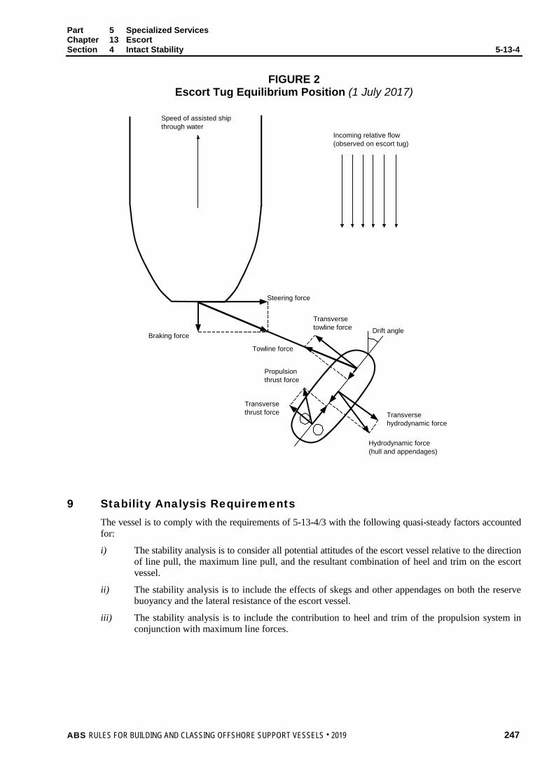
Part 5 Specialized Services Chapter 13 Escort Section 4 Intact Stability 5-13-4
FIGURE 2 Escort Tug Equilibrium Position (1 July 2017)
Speed of assisted ship through water
Braking force
Steering force
Incoming relative flow(observed on escort tug)
Drift angle
Towline force
Transverse towline force
Transverse hydrodynamic force
Hydrodynamic force (hull and appendages)
Propulsion thrust force
Transverse thrust force
9 Stability Analysis Requirements The vessel is to comply with the requirements of 5-13-4/3 with the following quasi-steady factors accounted for:
i) The stability analysis is to consider all potential attitudes of the escort vessel relative to the direction of line pull, the maximum line pull, and the resultant combination of heel and trim on the escort vessel.
ii) The stability analysis is to include the effects of skegs and other appendages on both the reserve buoyancy and the lateral resistance of the escort vessel.
iii) The stability analysis is to include the contribution to heel and trim of the propulsion system in conjunction with maximum line forces.
ABS RULES FOR BUILDING AND CLASSING OFFSHORE SUPPORT VESSELS . 2019 247

P A R T S e c t i o n 5 : T o w i n g G e a r
5 C H A P T E R 13 Escort
S E C T I O N 5 Towing Gear
1 Arrangement The towing hook, towing winch, towing bitt or towing bollard is to be located as low as practicable. For escort vessels which normally tow over the stern and have the main towline connection to the hull ahead of the propellers, the location of the towline connection is to be close to but abaft the center of gravity of the escort vessel in the expected towing condition.
Rollers or fairleads are to be arranged so as to contain the towline within the design limits of its sweep. The towing arrangement is to be such that the towline lead does not come into contact with the vessel’s superstructure or deckhouse in any expected towing condition.
Effective means are to be provided to lead and restrain the towline over the stern of escort vessels which normally tow over the stern.
3 Safety Measures (2016)
3.1 Quick Release Device A quick release device for the towing hook or towing winch is to be provided. The quick release device is to be operable from the bridge or other normally manned location in direct communication with the bridge. The quick release device is to disengage the towline at any combination of expected trim and heel.
3.3 Weak Link In addition to quick release mechanism, the towline shall be provided with a weak link. Break load of weak link not to exceed applied load as per 5-13-5/5.5.
5 Strength
5.1 Towline The breaking strength of the towline is not to be less than two times the static bollard pull load.
5.3 Towing Hook, Towing Winch, Towing Bollard and Towing Bitts (2017) Towing hook, towing winch, towing bollard and towing bitt are to be capable of sustaining the breaking strength of the towline without permanent deformation. These items are to comply with a recognized standard or code of practice. Nameplate indicating the names of standard, rated load, speed, mass, etc., will be acceptable for that purpose. Other means for verifying compliance will also be considered.
Towing winch and its accessories to be in accordance with 5-3-4/7.
The installation of these items is to be to the satisfaction of the Surveyor.
248 ABS RULES FOR BUILDING AND CLASSING OFFSHORE SUPPORT VESSELS . 2019

Part 5 Specialized Vessels and Services Chapter 13 Escort Section 5 Towing Gear
5.5 Supporting Structure (2018) The stresses in the structures supporting the items in 5-13-5/5.3 are not to exceed the following permissible stresses when subjected to a load equal to at least two times the estimated braking/steering forces based on Escort prediction from computer modeling program or two times the static bollard pull, whichever is greater, applied horizontally within a range of 90° from centerline on each side of the vessel.
Normal Stress 0.75 Y
Shear Stress 0.45 Y
where Y is specified minimum yield strength or yield point of the material. When the evaluation of the winch supporting structure is carried out by direct analysis using finite element methods, refer to 3-2-20/Table 2 for stress limits.
In addition, the buckling strength is to be adequate for the above loading.
Doubler plates are not allowed between the foundations of the items in 5-13-5/5.3 and the deck plating. A thicker insert plate is to be provided, if necessary.
5.7 Connections The size and arrangement of foundation securing bolts and welds for towing hook or towing winch are to be in accordance with a recognized standard.
ABS RULES FOR BUILDING AND CLASSING OFFSHORE SUPPORT VESSELS . 2019 249

P A R T S e c t i o n 6 : V e s s e l D e s i g n
5 C H A P T E R 13 Escort
S E C T I O N 6 Vessel Design
1 Hull Design A bulwark is to be fitted around the lowest weather deck. See 3-2-17/1.1 and 3-2-17/1.3.
3 Side Structures (2014) For vessels subject to impact loads during routine operation, see 3-2-2/3.11, 3-2-5/11, and 3-2-6/11.
5 After Deck Deck fittings within the sweep of towline are to be protected against contact with the towline, and against towline fouling.
7 Weather Deck Openings Openings in the weather deck intended to be used at sea and leading to spaces below the freeboard or superstructure deck, including emergency exits, are to be protected as required in 3-2-15/21.3 with sill height of doors at least as required by 3-2-15/21.7 for companionways.
Access openings, including emergency exits, are to be located clear of the towline sweep area.
9 Line Handling Equipment Power line handling equipment is to be provided. The towline winch is to be of good and substantial make, suitable for the size of the intended towline. The winch is to be adequately bolted down to a substantial bed or foundation, and deck beams below the winch are to be suitably strengthened and additionally supported. See 5-13-5/5 for strength requirements of towing components, supporting structure and connections.
11 Fendering (2014) Escort vessels are to be fully fendered to preclude damage in the event of contact between the escort vessel and the designated ship. Fender is to be arranged such that fender system is not stressed beyond its design limits. See 5-10-3/1.3 and 5-10-3/1.5 where steel fender is fitted.
13 Equipment Equipment is to be in accordance with Section 3-5-1. The number, weight and size of equipment differing from 3-5-1/Table 1 may be specially considered for limited service. See also 1-1-3/11 of the ABS Rules for Conditions of Classification (Part 1).
250 ABS RULES FOR BUILDING AND CLASSING OFFSHORE SUPPORT VESSELS . 2019

P A R T S e c t i o n 7 : V e r i f i c a t i o n o f S t e e r i n g C a p a b i l i t y
5 C H A P T E R 13 Escort
S E C T I O N 7 Verification of Steering Capability
1 Full Scale Testing Requirements The following data is to be collected at the full scale trials:
i) A continuous recording of the ship’s and escort vessel’s positions during the course of the trial
ii) A recording of the ship’s and escort vessel’s headings during the course of the trial
iii) Towline tension
iv) Angle of towline
v) Heel angle of escort vessel
Readings for ii) through v) are to be taken at a maximum interval of 10 seconds.
Environmental conditions are to be noted, including weather, sea state, wind, current, water depth. The ship’s and escort vessel’s loading conditions are also to be noted.
3 Computer Model Simulation Requirements (2014)
3.1 General The computer modeling program should be suitable to the type of ship and escort vessel being modeled. It should also be suitable for the waterway bathymetry being modeled. The calculation for the steering capability of the escort vessel should correspond to a quasi-steady state condition where the horizontal-plane forces and moments are balanced. Non-linear effects can be considered negligible.
The analysis is to include the hydrodynamic forces on the escort vessel’s hull and underwater appendages, the forces acting on the rudder, and the propulsive thrust. Escort vessel stability and attitude is to be considered in the analysis.
3.3 Steering Capability Steering capability of escort vessels analyzed to verify its ability to tow the disabled ship at a specified speed in calm conditions and holding it in a steady position against specified head wind. Where escort vessel working in contact with disabled ship’s hull, steering capability will be reviewed on case by case basis.
The factors to be included in analysis are forces and moments, angles of attack of the hull and skeg to free stream, heel angles, wave run up and residual freeboard. The quasi-equilibrium to be calculated to deck edge submergence only.
3.5 Computer Model Simulation The computer model simulation is to include the following components of a steady-state escort vessel performance analysis:
i) Lift, drag and center of pressure of hull
ii) Lift, drag and center of pressure of skeg including effects of aspect ratio
iii) Cross-flow effects as a result of tug orientation with respect to the free stream
ABS RULES FOR BUILDING AND CLASSING OFFSHORE SUPPORT VESSELS . 2019 251

Part 5 Specialized Vessels and Services Chapter 13 Escort Section 7 Verification of Steering Capability
iv) Effects of fendering on hydrodynamic performance of the hull
v) Propeller performance, including engine, gearbox, and shafting characteristics, command RPM and propeller geometry
vi) Effects of twin screw control
vii) Lift, drag and center of pressure of propeller nozzles, if applicable
viii) Heeling moments caused by bow lines (if rigged) and transverse components of hull, skeg, rudder, nozzle and propeller forces
ix) Heeling moment caused by towline tension
x) Freeboard and GM in the design condition and escort condition
xi) Reduction in freeboard as result of average wave amplitudes
xii) Deck edge submergence
xiii) Forces in lines
xiv) Position of tug on ship, either alongside on the transom or on a line
xv) Use of additional thrusters, if necessary
3.7 Conventional Vessels with Rudder For conventional escort vessels with rudder arrangement, the following additional components to be included in performance analysis:
i) Lift, drag and center of pressure of rudders, based on published flat plate and lifting surface conditions, including effects of aspect ratio and edge effects
ii) Modification of flow into rudders resulting from hull shape
iii) Modification of flow into rudders resulting from momentum changes induced by the propellers
iv) Position of rudders with respect to propellers and local rudder angles
252 ABS RULES FOR BUILDING AND CLASSING OFFSHORE SUPPORT VESSELS . 2019

P A R T S e c t i o n 8 : T e s t s a n d S u r v e y s
5 C H A P T E R 13 Escort
S E C T I O N 8 Tests and Surveys
1 Static Bollard Pull Test The static bollard pull test procedure is to be submitted for review by the attending Surveyor in advance of the test.
A bollard pull test is required for each vessel being classed Escort Service.
The static bollard pull is to be measured with the escort vessel at the maximum continuous rpm, and at or near its maximum displacement. It is the pull that is recorded over the state of equilibrium without any tendency to decline.
The depth of water, and the extent of water abaft and abreast the vessel are to be adequate to give a reliable bollard pull.
For additional test criteria, see Appendix 5-3-A1 “Guidelines for Bollard Pull Test Procedure” of these Rules.
3 Quick Release Test The effectiveness of the quick release device is to be demonstrated during initial sea trial. The test is to be conducted to manufacturer’s recommendations.
5 Surveys Surveys after construction are to be in accordance with the ABS Rules for Survey after Construction (Part 7).
7 Winch Test (2017) Escort winch and its accessories are to be tested in accordance with 5-3-4/7.
ABS RULES FOR BUILDING AND CLASSING OFFSHORE SUPPORT VESSELS . 2019 253
P A R T C h a p t e r 1 4 : W i n d T u r b i n e I n s t a l l a t i o n , M a i n t e n a n c e a n d R e p a i r ( W i n d I M R )
5 C H A P T E R 14 Wind Turbine Installation, Maintenance and
Repair (Wind IMR)
CONTENTS SECTION 1 General .................................................................................................. 255
1 Application ....................................................................................... 255 3 Scope .............................................................................................. 255 5 Classification ................................................................................... 255
5.1 Dual and Multi Purpose Vessels .................................................. 255 7 Submission of Data ......................................................................... 255
SECTION 2 Vessel Design ....................................................................................... 256
1 Work Deck ....................................................................................... 256 1.1 Reinforcements ............................................................................ 256 1.3 Arrangement ................................................................................ 256
3 Hull Arrangement and Strength ...................................................... 256 5 Cranes ............................................................................................. 256
5.1 Certification of Cranes ................................................................. 256 5.3 Crane Pedestal and Supporting Structure ................................... 256 5.5 Mobile Crane Installations ............................................................ 256
7 Supporting Structure for Pile Driving Equipment ............................ 256 9 Dynamic Positioning Systems ......................................................... 257
SECTION 3 Stability .................................................................................................. 258
1 Intact Stability .................................................................................. 258 1.1 Deck Cargo .................................................................................. 258
SECTION 4 Tests, Trials, and Surveys ................................................................... 259
1 General ........................................................................................... 259
254 ABS RULES FOR BUILDING AND CLASSING OFFSHORE SUPPORT VESSELS . 2019
P A R T S e c t i o n 1 : G e n e r a l
5 C H A P T E R 14 Wind Turbine Installation, Maintenance and
Repair (Wind IMR)
S E C T I O N 1 General
1 Application (1 July 2012) The requirements in this Chapter apply to vessels intended for unrestricted service which are primarily engaged in installation, maintenance and repair of offshore wind turbines and may include various equipment used to perform or support functions such as pile driving, installation, maintenance and repair of jacket, tower, nacelle and/or blades.
3 Scope (1 July 2012) This Chapter addresses the safety aspects related to wind turbine installation, maintenance and repair operations on vessels without self-elevating capability.
For other types of wind turbine installation units, including vessels with self-elevating capability refer to Chapter 8, Section 6 of the ABS Guide for Building and Classing Mobile Offshore Units (MOU Guide).
5 Classification In accordance with Section 1-1-2 of the OSV Rules Supplement to the ABS Rules for Conditions of Classification (Part 1) and 5-1-1/5.1 of these Rules, the classification À A1 Offshore Support Vessel (Wind IMR) will be assigned to vessels built in compliance with these requirements and other relevant sections of these Rules.
5.1 Dual and Multi Purpose Vessels Vessels intended for wind turbine installations and providing additional services may be classed with combinations of the applicable notations for the relevant service as explained in Section 5-1-1 of these Rules.
In such instances, the dual or multipurpose vessel is to be designed and built to these requirements, as well as to those applicable for the particular additional service or services.
7 Submission of Data The documentation required in addition to the general plans listed in Section 1-1-4 of the OSV Rules Supplement to the ABS Rules for Conditions of Classification (Part 1) is specified in Section 5-14-2 depending on the equipment installed and characteristics of the vessels.
ABS RULES FOR BUILDING AND CLASSING OFFSHORE SUPPORT VESSELS . 2019 255

P A R T S e c t i o n 2 : V e s s e l D e s i g n
5 C H A P T E R 14 Wind Turbine Installation, Maintenance and
Repair (Wind IMR)
S E C T I O N 2 Vessel Design
1 Work Deck
1.1 Reinforcements The provisions in 5-9-3/1.1 for work deck reinforcements are applicable.
1.3 Arrangement The working deck, as far as possible, is to be kept unobstructed, clear of engine room intakes and exhaust from tank vents and mooring equipment. Tank vents, mooring and deck access provisions are preferably to be grouped in way of the aft deck, boom rest and/or forecastle.
3 Hull Arrangement and Strength The provisions in 5-9-3/3 for hull arrangement and strength are applicable. All load effects caused by deck cargo and heavy equipment are to be accounted for in the design calculations for all operational scenarios.
5 Cranes
5.1 Certification of Cranes Any crane permanently installed on board the crane unit and intended for operations other than supply of provisions and maintenance of the unit is to be certified by ABS in accordance with Chapter 2 of the Lifting Appliances Guide or API Spec. 2C.
5.3 Crane Pedestal and Supporting Structure Crane supporting structure is to comply with the requirements of 5-9-3/7.
5.5 Mobile Crane Installations Mobile cranes not permanently attached to the unit structure, such as crawler cranes, are not required to be certified. Means for securing the crane in parked position at sea in vessel’s transit mode is to be provided taking into account environmental load conditions.
7 Supporting Structure for Pile Driving Equipment (1 July 2012) If pile driving equipment is installed, detailed drawings of the foundation and supporting structure on which the pile driving rig and supporting equipment are installed are to be submitted for review. The hull supporting structure is also to be designed to resist the design static and dynamic loading conditions of the pile driving equipment using the allowable stresses defined in 3-2-20/9. In addition, the foundation and supporting structure are to be designed to resist motion-induced loads in severe storm, normal operating and transit conditions using the allowable stresses defined in 3-2-20/9.
256 ABS RULES FOR BUILDING AND CLASSING OFFSHORE SUPPORT VESSELS . 2019

Part 5 Specialized Services Chapter 14 Wind Turbine Installation, Maintenance and Repair (Wind IMR) Section 2 Vessel Design 5-14-2
9 Dynamic Positioning Systems Dynamic positioning systems, when used to maintain the vessel’s position during installation, maintenance, and repair operations, are to comply with the requirements of the applicable DPS class notation in the ABS Guide for Dynamic Positioning Systems. Appropriate risk assessment and engineering analysis should be used to determine the applicable DPS notation.
ABS RULES FOR BUILDING AND CLASSING OFFSHORE SUPPORT VESSELS . 2019 257

P A R T S e c t i o n 3 : S t a b i l i t y
5 C H A P T E R 14 Wind Turbine Installation, Maintenance and
Repair (Wind IMR)
S E C T I O N 3 Stability
1 Intact Stability When complying with the stability criteria in Section 3-3-1 and Appendix 5-9-A1, the additional guidance in 5-14-3/1.1 is to be followed. Stability calculations and corresponding information for the Master are to be submitted for review and approval. The submission of evidence showing approval by an Administration of stability of the vessel for the wind turbine IMR operations in accordance with a recognized standard may be accepted in lieu of a review of stability by ABS.
1.1 Deck Cargo i) The loading conditions are to cover the full range of operating configurations, from no deck cargo
on board to the maximum design deck load.
ii) The projected area of the deck cargo is to be included in the calculations for compliance with the Severe Wind and Rolling Criteria, 3-3-A1/3.3.
iii) If the vessel is intended to carry deck cargoes that may accumulate water, such as open cargo bins, the appropriate free surface correction is to be applied to all conditions.
iv) If pipes are carried as deck cargo, refer to 3-3-A1/11.
258 ABS RULES FOR BUILDING AND CLASSING OFFSHORE SUPPORT VESSELS . 2019

P A R T S e c t i o n 4 : T e s t s , T r i a l s , a n d S u r v e y s
5 C H A P T E R 14 Wind Turbine Installation, Maintenance and
Repair (Wind IMR)
S E C T I O N 4 Tests, Trials, and Surveys
1 General To assist in survey, the vessel is to be provided with approved crane manuals on board, accessible to the Surveyor, refer 5-9-4/1.
Installation of the crane, supporting machinery and systems on the vessels is to be to the satisfaction of the attending Surveyor.
After each crane has been erected onboard, and before it is placed in service, the functional integration tests of the crane systems and load tests are to be conducted in the presence of the Surveyor. A record of these tests and other information concerning initial certification is to be readily available.
Jacking equipment and systems are to be tested in accordance with the specifications of the owner and in the presence of a Surveyor, refer to 4-1/5 of the MOU Guide.
If applicable, the dynamic positioning system is to be tested in accordance with Section 7 of the ABS Guide for Dynamic Positioning Systems.
ABS RULES FOR BUILDING AND CLASSING OFFSHORE SUPPORT VESSELS . 2019 259

P A R T C h a p t e r 1 5 : C a b l e L a y i n g
5 C H A P T E R 15 Cable Laying (1 July 2012)
CONTENTS SECTION 1 General .................................................................................................. 262
1 Application ....................................................................................... 262 3 Classification ................................................................................... 262 5 Submission of Data ......................................................................... 262
5.1 Hull Plans ..................................................................................... 262 5.3 Cable Laying Plans and Data for Approval .................................. 262 5.5 Design Analysis ........................................................................... 262 5.7 Additional Information .................................................................. 263 5.9 Supporting Systems ..................................................................... 263
SECTION 2 Seakeeping ............................................................................................ 264
1 Stability ............................................................................................ 264 1.1 Stability of Cable Laying Vessels ................................................. 264
3 Station Keeping ............................................................................... 264 3.1 Station Keeping with Anchors and Cables ................................... 264 3.3 Dynamic Positioning System ....................................................... 264
5 Loading Conditions ......................................................................... 265 5.1 Loading Conditions ...................................................................... 265
SECTION 3 Vessel Design and Arrangements ...................................................... 266
1 General ........................................................................................... 266 3 Cranes ............................................................................................. 266 5 Supporting Structure Design Loads ................................................ 266
5.1 Lifting Loads ................................................................................ 266 5.3 Other Loads ................................................................................. 266 5.5 Allowable Stresses ...................................................................... 266
SECTION 4 Cable Laying Equipment and Systems .............................................. 267
1 General ........................................................................................... 267 3 Cable-lay Systems Arrangement .................................................... 267
3.1 Control System ............................................................................ 267 3.3 Communications .......................................................................... 267
5 Cable-lay Equipment and Systems ................................................. 267 5.1 Cable Drums, Reels, Deployment Sheaves and Support
Structure ...................................................................................... 267
260 ABS RULES FOR BUILDING AND CLASSING OFFSHORE SUPPORT VESSELS . 2019

7 Offshore Construction Supporting Equipment ................................ 268 7.1 Remote Operated Vehicles (ROVs) ............................................ 268 7.3 Dynamic Tracking System ........................................................... 268
SECTION 5 Tests, Trials, and Surveys ................................................................... 269
1 General ........................................................................................... 269
ABS RULES FOR BUILDING AND CLASSING OFFSHORE SUPPORT VESSELS . 2019 261
P A R T S e c t i o n 1 : G e n e r a l
5 C H A P T E R 15 Cable Laying
S E C T I O N 1 General
1 Application The requirements in this Chapter apply to vessels intended for unrestricted service that are primarily engaged in installation, maintenance and repair of underwater telecommunication cables and power transmission cables.
3 Classification In accordance with Section 1-1-2 of the OSV Rules Supplement to the ABS Rules for Conditions of Classification (Part 1), the classification À A1 Offshore Support Vessel (Cable Lay) will be assigned to vessels built in compliance with these requirements and other relevant sections of these Rules.
5 Submission of Data In general, in addition to the plans listed in Section 1-1-4 of the OSV Rules Supplement to the ABS Rules for Conditions of Classification (Part 1), the following plans, calculations and particulars are to be submitted.
5.1 Hull Plans For a list of drawings to be submitted together with the Trim and Stability Booklet for ABS review, refer to 3-3-A1/17.
5.3 Cable Laying Plans and Data for Approval i) Hull structural details related to cable laying
ii) Equipment and installations for cable laying
iii) Supporting structures for equipment engaged in the cable laying
iv) Equipment for station-keeping/maneuvering during cable laying.
5.5 Design Analysis The following calculations are to be submitted and documented.
• Calculations demonstrating the adequacy of the vessel’s stability during all cable laying operations. See also 5-15-2/1.
• Calculations demonstrating adequacy of maneuvering power required for the vessel to maintain station during cable laying operations.
• Calculations for the supporting structure in way of all cable laying and cable storing equipment interfaces with the ship structure.
• Design loads and allowable deflection at each foundation of the cable laying and cable storing equipment
262 ABS RULES FOR BUILDING AND CLASSING OFFSHORE SUPPORT VESSELS . 2019
Part 5 Specialized Services Chapter 15 Cable Laying Section 1 General 5-15-1
5.7 Additional Information The following items are to be submitted:
• Arrangement plans showing the locations of all cable laying equipment and control stations
• Support arrangement for equipment used in cable laying operations such as cable drum, cable reels; maximum forces are to be stated.
• Location and support details of the cranes; reaction forces are to be stated.
• Supporting structures for cable stowed on racks in holds and/or deck; maximum weights are to be stated.
• Supporting structures for cable drum and reels in holds and/or deck; maximum weights are to be stated.
• Descriptions of equipment for moving skid frames, substructures, including piping and electrical systems, details of mechanical components, including hold-down devices and applicable strength calculations.
5.9 Supporting Systems • Electrical schematics, load analysis, short circuits analysis and coordination study for the vessel’s electrical
systems supplying cable laying.
• Piping schematics and calculations for the vessel’s piping systems supplying cable laying systems.
• Arrangement and details of communication systems between the vessel and cable laying systems.
ABS RULES FOR BUILDING AND CLASSING OFFSHORE SUPPORT VESSELS . 2019 263
P A R T S e c t i o n 2 : S e a k e e p i n g
5 C H A P T E R 15 Cable Laying
S E C T I O N 2 Seakeeping
1 Stability
1.1 Stability of Cable Laying Vessels 1.1.1
In evaluating the loading conditions for cable laying vessels, the following loads are to be included:
i) The overturning moments due to environmental and operational loads on the cable laying devices are to be included. When the cable laying device is movable from stowage to operating condition, the full range of laying device positions is to be considered in order to investigate the most critical scenarios.
ii) The effect of the cable drum and reels in the stability analysis is to be assessed for each operating condition.
iii) If the vessel is fitted with or carries open cargo bins on the deck that may accumulate water, either effective means to drain water from these spaces shall be provided or an appropriate free surface correction applied.
iv) Carriage of cable as deck cargo – see 3-3-A1/11 for the requirements for the carriage of cable on deck.
v) Where large and heavy equipment or structures are intended to be stowed on deck, the estimated weight and height of the center of gravity in the worst possible scenario are to be considered in the stability analysis.
1.1.2 Cable laying vessels equipped with lifting devices in addition to the cable laying device(s) are to comply with Appendix 5-9-A1.
3 Station Keeping Cable laying vessels are to be capable of maintaining their positions safely during cable laying operations. The means to maintain position may be a mooring system with anchors or a dynamic positioning system.
3.1 Station Keeping with Anchors and Cables Position mooring with anchors, cables and mooring winches when used to maintain the vessel’s position during cable laying operations, are to comply with the requirements for the class notation  or à (see Section 3-4-1 of the ABS Rules for Building and Classing Mobile Offshore Drilling Units (MODU Rules)). Safety precautions are to be considered to prevent damaging seabed equipment and installations by anchor deployment, recovery and station keeping.
3.3 Dynamic Positioning System Dynamic positioning systems, when used to maintain the vessel’s position during cable laying operations, are to comply with the requirements for the class notation DPS-2 or DPS-3 (see the ABS Guide for Dynamic Positioning Systems).
264 ABS RULES FOR BUILDING AND CLASSING OFFSHORE SUPPORT VESSELS . 2019

Part 5 Specialized Services Chapter 15 Cable Laying Section 2 Seakeeping
5 Loading Conditions
5.1 Loading Conditions Loading conditions covering departure and arrival in full load as well as ballast conditions, along with anticipated operational or intermediate conditions at site are to be included in the Trim and Stability Booklet of the vessel.
ABS RULES FOR BUILDING AND CLASSING OFFSHORE SUPPORT VESSELS . 2019 265
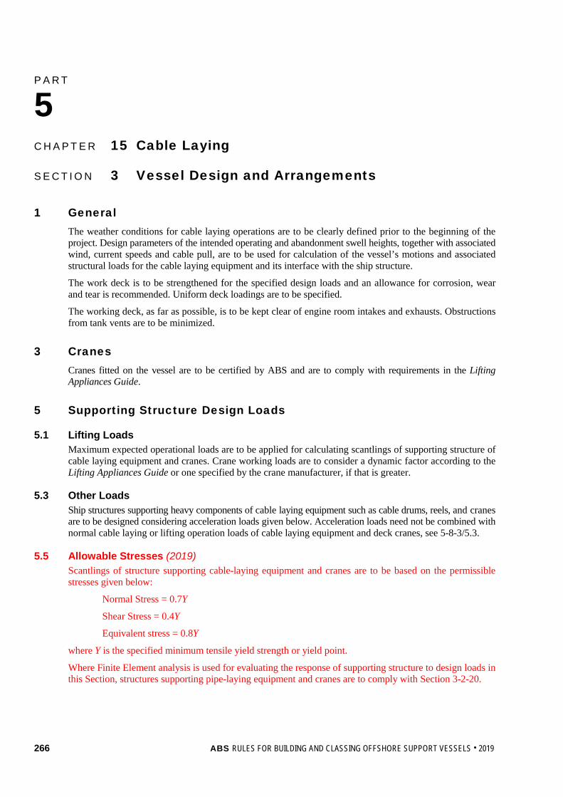
P A R T S e c t i o n 3 : V e s s e l D e s i g n a n d A r r a n g e m e n t s
5 C H A P T E R 15 Cable Laying
S E C T I O N 3 Vessel Design and Arrangements
1 General The weather conditions for cable laying operations are to be clearly defined prior to the beginning of the project. Design parameters of the intended operating and abandonment swell heights, together with associated wind, current speeds and cable pull, are to be used for calculation of the vessel’s motions and associated structural loads for the cable laying equipment and its interface with the ship structure.
The work deck is to be strengthened for the specified design loads and an allowance for corrosion, wear and tear is recommended. Uniform deck loadings are to be specified.
The working deck, as far as possible, is to be kept clear of engine room intakes and exhausts. Obstructions from tank vents are to be minimized.
3 Cranes Cranes fitted on the vessel are to be certified by ABS and are to comply with requirements in the Lifting Appliances Guide.
5 Supporting Structure Design Loads
5.1 Lifting Loads Maximum expected operational loads are to be applied for calculating scantlings of supporting structure of cable laying equipment and cranes. Crane working loads are to consider a dynamic factor according to the Lifting Appliances Guide or one specified by the crane manufacturer, if that is greater.
5.3 Other Loads Ship structures supporting heavy components of cable laying equipment such as cable drums, reels, and cranes are to be designed considering acceleration loads given below. Acceleration loads need not be combined with normal cable laying or lifting operation loads of cable laying equipment and deck cranes, see 5-8-3/5.3.
5.5 Allowable Stresses (2019) Scantlings of structure supporting cable-laying equipment and cranes are to be based on the permissible stresses given below:
Normal Stress = 0.7Y
Shear Stress = 0.4Y
Equivalent stress = 0.8Y
where Y is the specified minimum tensile yield strength or yield point.
Where Finite Element analysis is used for evaluating the response of supporting structure to design loads in this Section, structures supporting pipe-laying equipment and cranes are to comply with Section 3-2-20.
266 ABS RULES FOR BUILDING AND CLASSING OFFSHORE SUPPORT VESSELS . 2019

P A R T S e c t i o n 4 : C a b l e L a y i n g E q u i p m e n t a n d S y s t e m s
5 C H A P T E R 15 Cable Laying
S E C T I O N 4 Cable Laying Equipment and Systems
1 General Unless requested by the owner and exceptions specified in 5-15-4/5, equipment and systems used solely for cable laying operations are in general not subject to Classification by ABS, provided they are designed and constructed in compliance with an applicable recognized standard. The recognized standard used in design of cable laying equipment and systems is to be specified by designer and acceptable to ABS. A manufacturer’s affidavit or other acceptable documentation to verify compliance with applicable recognized standards is to be submitted to ABS. Their installations and onboard testing are to be supervised in the aspects of operational safety as to reduce to a minimum any danger to persons on board and marine pollution, due regard to be paid to moving parts, hot surfaces and other hazards. Considerations are to be given to the consequences of the failure of systems and equipment essential to the safety of the vessel.
3 Cable-lay Systems Arrangement
3.1 Control System A central control station is to be provided for controlling or coordinating the operations of the cable laying equipment. The central control station is to be located at a position that allows the operating personnel to have a clear view of the cable departure location and to provide an overview of all systems and activities associated with the cable laying operations.
3.3 Communications The cable laying central control station and the vessel station keeping control station are to be linked by a hard-wired communication system and a manually operated alarm system. Means of communications are to be provided between the central control station and the local control stations for the cable laying equipment.
5 Cable-lay Equipment and Systems
5.1 Cable Drums, Reels, Deployment Sheaves and Support Structure Cable drums and reels are to be designed, constructed and installed in accordance with a recognized standard.
Cable drum, reel and deployment sheave support structure including the reinforcements for the hull are to be designed to adequately resist the load effects of pipes, risers or reels imposed on the supports in the severe storm, normal operating and transit conditions with the allowable stresses defined in 5-8-3/5.5. Considerations should also be given to the unit in damaged conditions, where the cable reel support structure are to withstand the load effects caused by the trim and heel of the vessel with the allowable stresses defined in 5-8-3/5.5.
ABS RULES FOR BUILDING AND CLASSING OFFSHORE SUPPORT VESSELS . 2019 267

Part 5 Specialized Services Chapter 15 Cable Laying Section 4 Cable Laying Equipment and Systems
7 Offshore Construction Supporting Equipment
7.1 Remote Operated Vehicles (ROVs) When the vessel is equipped with work-class ROV to carry out underwater works such as cable burying, cable cutting and recovery for repairing, its handling system and control station are to be arranged in accordance with Sections 17 and 18 of the Underwater Rules.
Deck foundations, fastening arrangements and vessel structures are to be designed in accordance with 5-5-3/5.
7.3 Dynamic Tracking System Where the dynamic tracking system for the laid cables interfaces with vessel’s data and control networks, provision is to be made to ensure that the operation or reliability of the vessel’s systems are not degraded.
268 ABS RULES FOR BUILDING AND CLASSING OFFSHORE SUPPORT VESSELS . 2019
P A R T S e c t i o n 5 : T e s t s , T r i a l s , a n d S u r v e y s
5 C H A P T E R 15 Cable Laying
S E C T I O N 5 Tests, Trials, and Surveys
1 General Installation of the cable laying equipment and systems on cable laying vessels is to be to the satisfaction of the attending Surveyor.
Upon installation, functional integration tests of the cable laying systems on board to the extent and as per the method agreed are to be carried out to the satisfaction of the attending Surveyor.
Position mooring equipment is to be tested in accordance with the specifications of the owner and in the presence of a Surveyor.
Dynamic positioning system is to be tested in accordance with Section 7 of the ABS Guide for Dynamic Positioning Systems.
ABS RULES FOR BUILDING AND CLASSING OFFSHORE SUPPORT VESSELS . 2019 269

270 ABS RULES FOR BUILDING AND CLASSING OFFSHORE SUPPORT VESSELS . 2019
P A R T C h a p t e r 1 6 : S u b s e a S e r v i c e s
5 C H A P T E R 16 Subsea Services (1 July 2019)
CONTENTS SECTION 1 General .................................................................................................. 272
1 Application ....................................................................................... 272 3 Scope .............................................................................................. 272 5 Classification ................................................................................... 273
5.1 Dual and Multi-Purpose Vessels .................................................. 273 7 Submission of Data ......................................................................... 273
7.1 Hull Plans ..................................................................................... 273 7.3 Crane Plans and Data.................................................................. 273 7.5 Design Analysis ........................................................................... 273 7.7 Additional Data ............................................................................ 273
9 Vessels without Subsea Service Class Notation ............................ 274 SECTION 2 Seakeeping ............................................................................................ 275
1 Stability ............................................................................................ 275 1.1 General ........................................................................................ 275 1.3 Deck Cargo .................................................................................. 275
3 Station Keeping ............................................................................... 275 3.1 Station Keeping with Anchors and Cables ................................... 275 3.3 Dynamic Positioning System ....................................................... 275
5 Loading Conditions ......................................................................... 276 SECTION 3 Vessel Design and Equipment ............................................................ 277
1 Work Deck ....................................................................................... 277 1.1 Arrangement ................................................................................ 277 1.3 Reinforcements ............................................................................ 277 1.5 Moon Pools .................................................................................. 277 1.7 Deck Covering ............................................................................. 278 1.9 Securing Deck Cargo ................................................................... 278 1.11 Cargo Rail .................................................................................... 278
3 Hull Arrangement and Strength ...................................................... 278 5 Cargo Tanks .................................................................................... 278 7 Cranes ............................................................................................. 278
7.1 Certification of Cranes ................................................................. 278 7.3 Crane Pedestal and Supporting Structure ................................... 278 7.5 Mobile Crane ............................................................................... 278
9 Remotely Operated Vehicles (ROVs) Support Systems................. 278 11 Equipment and Systems for Subsea Support Operations .............. 278

ABS RULES FOR BUILDING AND CLASSING OFFSHORE SUPPORT VESSELS . 2019 271
13 Carriage of Limited Amounts of Hazardous and Noxious Liquid Substances ..................................................................................... 279
SECTION 4 Supporting Machinery and Systems.................................................. 280
1 Power System ................................................................................. 280 1.1 Crane with Self-Contained or Independent Power Plant ............. 280 1.3 Crane Driven by Vessel's Power System .................................... 280
3 Heeling and Ballasting Systems ..................................................... 280 5 Crane Control and Communications ............................................... 280
5.1 Controls ....................................................................................... 280 5.3 Communications .......................................................................... 280
7 Machinery Installations ................................................................... 280 SECTION 5 Tests, Trials, and Surveys ................................................................... 281
1 General ........................................................................................... 281

272 ABS RULES FOR BUILDING AND CLASSING OFFSHORE SUPPORT VESSELS . 2019
P A R T S e c t i o n 1 : G e n e r a l
5 C H A P T E R 16 Subsea Services
S E C T I O N 1 General
1 Application The requirements for obtaining additional subsea service notation in this Chapter apply to vessels intended for unrestricted service and engaged primarily in installation support, inspection, maintenance, repair and/or decommissioning of subsea systems which may include but are not limited to subsea trees, wellhead, manifolds, equipment and facilities/structures. The associated operating activities of subsea services vessels may include:
• Installations of subsea Jumpers, pipeline end manifold (PLEM), pipeline end termination (PLET), inline sleds, subsea flying lead and suction piles etc.
• Inspection of risers, umbilical cords, pipelines, flexible joints, subsea equipment and field
• Pipeline pigging and repair support
• Maintenance of subsea production systems
• Permanent plugging and abandonment of the wellbores
• Flushing, cleaning and removal of subsea process equipment and facilities
• Removing some or all of the disposed conductors and subsea structures/facilities
• Transporting disposed hydrocarbons and chemicals, subsea structures/facilities and equipment
3 Scope The following aspects are covered by the Classification requirements in this Chapter:
• Hull Structure
• Supporting structures for equipment used in subsea support operations
• Equipment, machinery and systems for subsea lifting operations
• Equipment and machinery for anchoring and mooring related to subsea support operations
• Equipment and machinery for vessel positioning during subsea support operations
• Stability
• Safety aspects related to vessels for carrying deck cargoes, dry and liquid cargoes including flammable cargoes having a flashpoint (closed cup test) below 60°C (140°F), such as fuel oil, base oil and oil-based liquid mud.
If the vessels are intended to carry limited amounts of Hazardous and Noxious Liquid Substances (HNLS) and dangerous goods for flushing subsea facilities or transporting disposed hydrocarbons and chemicals, refer to 5-16-3/13.
Part 5 Specialized Services Chapter 16 Subsea Services Section 1 General 5-16-1
ABS RULES FOR BUILDING AND CLASSING OFFSHORE SUPPORT VESSELS . 2019 273
5 Classification In accordance with Section 1-1-2 of the OSV Rules Supplement to the ABS Rules for Conditions of Classification (Part 1) and 5-1-1/5.1 of these Rules, the classification À A1 Offshore Support Vessel (Subsea Service) will be assigned to vessels designed primarily for subsea service as defined in 5-16-1/1, and built to the requirements in this Chapter and other relevant sections of these Rules.
5.1 Dual and Multi-Purpose Vessels Vessels intended for subsea support services and providing additional services may be classed with combinations of the applicable notations for the relevant service as explained in Section 5-1-1.
In such instances, the dual or multipurpose vessel is to be designed and built to these requirements, as well as to those applicable for the particular additional service or services.
7 Submission of Data In general, in addition to the plans listed in Section 1-1-4 of the OSV Rules Supplement to the ABS Rules for Conditions of Classification (Part 1), the following plans, calculations and particulars are to be submitted.
7.1 Hull Plans For a list of drawings to be submitted together with the Trim and Stability Booklet for ABS review, refer to 3-3-A1/17.
7.3 Crane Plans and Data For a list of crane plans and data to be submitted for ABS review, refer to 5-9-1/7.3 and 5-9-1/7.7.
7.5 Design Analysis The following calculations are to be submitted:
• Calculations to demonstrate the adequacy of the vessel’s stability during subsea support operations. See also 5-16-2/1.
• Calculations to demonstrate adequacy of propulsion power required for the vessel to maintain station during subsea support operations or equivalent analysis.
• Calculations to demonstrate strength of the crane and supporting structures.
• Calculations to demonstrate strength of supporting structures for equipment applied in subsea support operations if applicable.
• Calculations to demonstrate strength of supporting structures for installation or disposed structures/ facilities and equipment transportation if applicable.
7.7 Additional Data The following items are to be submitted:
• Information regarding loading arrangement of deck cargoes, weights and their centers of gravity if applicable
• Structural details and arrangements of structures in way of cargo deck if applicable
• Lashing arrangement of deck cargoes if applicable
• The design deck cargo loads and location
• Details of integral liquid cargo tanks including vents and/or overflows height and location
• Details of independent liquid and/or dry cargo tanks
• Details of independent tank supports and fastening arrangements

Part 5 Specialized Services Chapter 16 Subsea Services Section 1 General 5-16-1
274 ABS RULES FOR BUILDING AND CLASSING OFFSHORE SUPPORT VESSELS . 2019
• Piping diagrams of liquid cargo transfer systems
• Piping diagrams of dry bulk cargo transfer systems
• Ventilation diagrams of liquid cargoes
• Arrangement in dry cargo compartment
9 Vessels without Subsea Service Class Notation When the class notation for subsea service has not been requested by the Owner, vessels intended for subsea service are to comply with the following minimum requirements given in 5-16-2/1, 5-16-2/5, 5-16-3/1, 5-16-3/3, 5-16-3/5, 5-16-3/7.3, 5-16-3/13, 5-16-4/3 and 5-16-4/7.

ABS RULES FOR BUILDING AND CLASSING OFFSHORE SUPPORT VESSELS . 2019 275
P A R T S e c t i o n 2 : S e a k e e p i n g
5 C H A P T E R 16 Subsea Services
S E C T I O N 2 Seakeeping
1 Stability
1.1 General In addition to complying with the stability criteria in Section 3-3-1 and Appendix 5-9-A1, the guidance in 5-16-2/1.3 is to be followed. Where large and heavy equipment or structures are intended to be stowed on deck, the estimated weight and height of the center of gravity in the worst possible scenario are to be considered in the stability analysis.
Stability calculations and corresponding information for the Master are to be submitted for review and approval. The submission of evidence showing approval by an Administration of stability of the vessel for the subsea support operations in accordance with a recognized standard may be accepted in lieu of a review of stability by ABS.
The dynamic load chart for each crane shall be included in the Trim and Stability Booklet and shall be posted at the crane operator's station in the clear view of the crane operator.
1.3 Deck Cargo The stability of vessel due to deck cargo on board is to be taken into account:
i) The loading conditions are to cover the full range of operating configurations, from no deck cargo on board to the maximum design deck load.
ii) The projected area of the deck cargo is to be included in the calculations for compliance with the Severe Wind and Rolling Criteria, 3-3-A1/3.3.
iii) If the vessel is intended to carry deck cargoes that may accumulate water, such as open cargo bins, the appropriate free surface correction is to be applied to all conditions.
iv) If pipes are carried as deck cargo, refer to 3-3-A1/11.
3 Station Keeping Subsea services vessels are to be capable of maintaining their position during subsea support operations. The means to maintain position may be a mooring system with anchors or a dynamic positioning system or a combination of both.
3.1 Station Keeping with Anchors and Cables Position mooring systems with anchors, cables and mooring winches when used to maintain the vessel’s position during subsea support operations are to comply with the requirements for the class notation à (see Section 3-4-1 of the MODU Rules).
3.3 Dynamic Positioning System Dynamic positioning systems, when used to maintain the vessel’s position during subsea support operations, are to comply with the requirements for the class notation DPS-2 or DPS-3 (see the ABS Guide for Dynamic Positioning Systems).

Part 5 Specialized Services Chapter 16 Subsea Services Section 2 Seakeeping 5-16-2
276 ABS RULES FOR BUILDING AND CLASSING OFFSHORE SUPPORT VESSELS . 2019
5 Loading Conditions Loading conditions covering departure and arrival in full load as well as ballast conditions, along with anticipated operational or intermediate conditions at site are to be included in the Trim and Stability Booklet of the vessel.
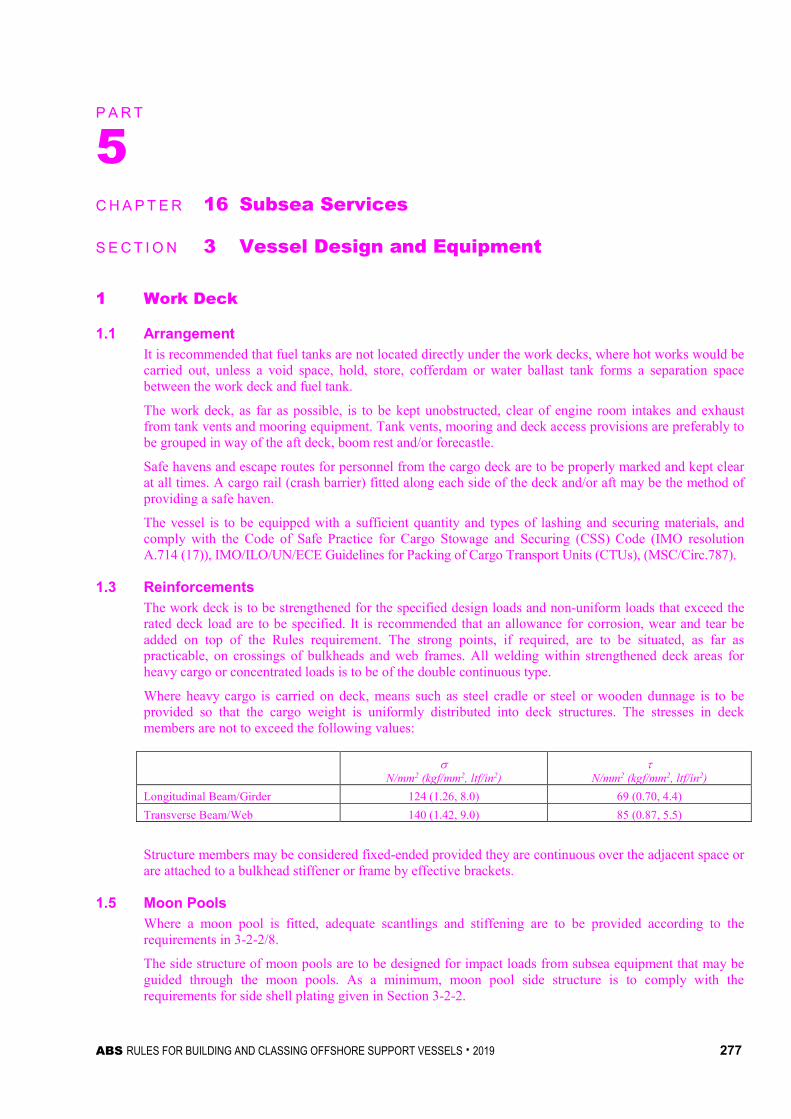
ABS RULES FOR BUILDING AND CLASSING OFFSHORE SUPPORT VESSELS . 2019 277
P A R T S e c t i o n 3 : V e s s e l D e s i g n a n d E q u i p m e n t
5 C H A P T E R 16 Subsea Services
S E C T I O N 3 Vessel Design and Equipment
1 Work Deck
1.1 Arrangement It is recommended that fuel tanks are not located directly under the work decks, where hot works would be carried out, unless a void space, hold, store, cofferdam or water ballast tank forms a separation space between the work deck and fuel tank.
The work deck, as far as possible, is to be kept unobstructed, clear of engine room intakes and exhaust from tank vents and mooring equipment. Tank vents, mooring and deck access provisions are preferably to be grouped in way of the aft deck, boom rest and/or forecastle.
Safe havens and escape routes for personnel from the cargo deck are to be properly marked and kept clear at all times. A cargo rail (crash barrier) fitted along each side of the deck and/or aft may be the method of providing a safe haven.
The vessel is to be equipped with a sufficient quantity and types of lashing and securing materials, and comply with the Code of Safe Practice for Cargo Stowage and Securing (CSS) Code (IMO resolution A.714 (17)), IMO/ILO/UN/ECE Guidelines for Packing of Cargo Transport Units (CTUs), (MSC/Circ.787).
1.3 Reinforcements The work deck is to be strengthened for the specified design loads and non-uniform loads that exceed the rated deck load are to be specified. It is recommended that an allowance for corrosion, wear and tear be added on top of the Rules requirement. The strong points, if required, are to be situated, as far as practicable, on crossings of bulkheads and web frames. All welding within strengthened deck areas for heavy cargo or concentrated loads is to be of the double continuous type.
Where heavy cargo is carried on deck, means such as steel cradle or steel or wooden dunnage is to be provided so that the cargo weight is uniformly distributed into deck structures. The stresses in deck members are not to exceed the following values:
σ N/mm2 (kgf/mm2, ltf/in2)
τ N/mm2 (kgf/mm2, ltf/in2)
Longitudinal Beam/Girder 124 (1.26, 8.0) 69 (0.70, 4.4) Transverse Beam/Web 140 (1.42, 9.0) 85 (0.87, 5.5)
Structure members may be considered fixed-ended provided they are continuous over the adjacent space or are attached to a bulkhead stiffener or frame by effective brackets.
1.5 Moon Pools Where a moon pool is fitted, adequate scantlings and stiffening are to be provided according to the requirements in 3-2-2/8.
The side structure of moon pools are to be designed for impact loads from subsea equipment that may be guided through the moon pools. As a minimum, moon pool side structure is to comply with the requirements for side shell plating given in Section 3-2-2.

Part 5 Specialized Services Chapter 16 Subsea Services Section 3 Vessel Design and Equipment 5-16-3
278 ABS RULES FOR BUILDING AND CLASSING OFFSHORE SUPPORT VESSELS . 2019
1.7 Deck Covering The requirements of protecting deck in 5-2-2/1.5 are to be complied with.
1.9 Securing Deck Cargo The requirements of securing deck cargo in 5-2-2/1.7 are to be complied with.
1.11 Cargo Rail Where cargo rails are fitted on cargo deck, the applicable requirements in 5-2-2/1.9 are to be complied with.
3 Hull Arrangement and Strength The provisions in 5-9-3/3 for hull arrangement and strength are applicable. All load effects caused by deck cargo and heavy equipment are to be accounted for in the design calculations for all operational scenarios.
For vessels subject to impact loads during routine operations, see 3-2-2/3.11, 3-2-5/11 and 3-2-6/11.
5 Cargo Tanks The requirements of cargo tanks in 5-2-2/3 are to be complied with. The requirements of cargo piping systems in 5-2-2/5 are to be complied with.
7 Cranes
7.1 Certification of Cranes Subsea cranes permanently installed on board are to be certified by ABS in accordance with Appendix 5-9-A2 and Chapter 2 of the Lifting Appliances Guide.
7.3 Crane Pedestal and Supporting Structure Crane supporting structure is to comply with the requirements of 5-9-3/7.
7.5 Mobile Crane Mobile cranes not permanently attached to the unit structure, such as crawler cranes, are not required to be certified. Means for securing the crane in parked position at sea in vessel’s transit mode is to be provided taking into account maximum environmental load conditions as specified by designers.
9 Remotely Operated Vehicles (ROVs) Support Systems When the vessel is equipped with work-class ROV to carry out underwater works, its handling system and control station are to meet the requirements in 5-5-4/3 and 5-5-4/5.
11 Equipment and Systems for Subsea Support Operations Unless requested by the owner, equipment and systems such as subsea jumpers, PLEMs, PLETs, underwater cutting systems and buoyancy clamps used for subsea operations are in general not subject to classification by ABS, provided they are designed and constructed in compliance with an applicable recognized standard. The recognized standards used in design of supporting equipment are to be specified by designer and acceptable to ABS. A manufacturer’s affidavit or other acceptable documentation to verify compliance with applicable recognized standards is to be submitted to ABS. Their installations and onboard testing are to be supervised in the aspects of operational safety as to reduce to a minimum any danger to persons on board and marine pollution, due regard to be paid to moving parts, hot surfaces and other hazards. Considerations are to be given to the consequences of the failure of systems and equipment essential to the safety of the vessel.
Part 5 Specialized Services Chapter 16 Subsea Services Section 3 Vessel Design and Equipment 5-16-3
ABS RULES FOR BUILDING AND CLASSING OFFSHORE SUPPORT VESSELS . 2019 279
13 Carriage of Limited Amounts of Hazardous and Noxious Liquid Substances Subsea services vessels which may not be constructed primarily to carry bulk cargoes, but which carry hazardous or noxious liquid substances in limited quantities, will also be subject to the provisions of Section 5-2-3 of these Rules which incorporate the guidelines in IMO Resolution A.673 (16) Guidelines for the Transport and Handling of Limited Amounts of Hazardous and Noxious Liquid Substances in Bulk on Offshore Support Vessel, as amended by IMO Resolutions MSC.236 (82) and MEPC.158 (55) or IMO Resolution A.1122(30), the Code for the Transport and Handling of Hazardous and Noxious Liquid Substances in Bulk on Offshore Support Vessels (OSV Chemical Code), as applicable.

280 ABS RULES FOR BUILDING AND CLASSING OFFSHORE SUPPORT VESSELS . 2019
P A R T S e c t i o n 4 : S u p p o r t i n g M a c h i n e r y a n d S y s t e m s
5 C H A P T E R 16 Subsea Services
S E C T I O N 4 Supporting Machinery and Systems
1 Power System
1.1 Crane with Self-Contained or Independent Power Plant Where the crane is fitted with self-contained or independent power plant with the prime mover, the requirements in 5-9-3/9.1.1 are to be complied with.
1.3 Crane Driven by Vessel's Power System Where the crane is driven by the vessel’s power systems, either hydraulic or electric, the vessel’s main power plant is to be sized with sufficient capacity to operate the crane under the load conditions defined in 5-16-4/1.1 and arranged so that the functioning of all safety equipment and essential services for vessel station keeping, stability and floatability are not impaired, jeopardized and degraded.
3 Heeling and Ballasting Systems Where heeling systems are provided to counteract the crane’s overturning moment, the systems are to be designed such that the vessel is capable of withstanding the sudden loss of the hook load in each condition of loading and operation. The free surface effects are to be considered for those tanks which are ballasted. Specific reference may be made to 5-9-A1/3.3.
5 Crane Control and Communications
5.1 Controls The requirements of crane control in 5-9-3/9.5.1 are to be complied with.
5.3 Communications Hard-wired communications are to be provided between the crane operator’s control station and the vessel’s station keeping control station
7 Machinery Installations The requirements of steering gear in 5-2-2/7.1 and engine exhaust outlets in 5-2-2/7.3 are to be complied with.

ABS RULES FOR BUILDING AND CLASSING OFFSHORE SUPPORT VESSELS . 2019 281
P A R T S e c t i o n 5 : T e s t s , T r i a l s , a n d S u r v e y s
5 C H A P T E R 16 Subsea Services
S E C T I O N 5 Tests, Trials, and Surveys
1 General To assist in survey, the vessel is to be provided with approved crane manuals on board, accessible to the Surveyor, refer 5-9-4/1.
Installation of the subsea cranes, supporting machinery and systems on the vessels is to be to the satisfaction of the attending Surveyor.
After each subsea crane has been erected on board, and before it is placed in service, the functional integration tests of the crane systems and load tests are to be conducted in the presence of the Surveyor. A record of these tests and other information concerning initial certification is to be readily available.
Suitable evidence is to be provided to the Surveyor to verify that ROV support systems installed on the subsea services vessels are certified by ABS or an IACS member Classification Society.
Upon installation, the ROV systems and their support vessel interfaces as well as the interfaces between the ROV systems installed on the support vessel are to be functionally tested to the satisfaction of the attending Surveyor.
Position mooring equipment is to be tested in accordance with the specifications of the owner and in the presence of a Surveyor.
If applicable, dynamic positioning system is to be tested in accordance with Section 7 of the ABS Guide for Dynamic Positioning Systems.