offshore survey in development projects
TRANSCRIPT
OFFSHORE SURVEY IN DEVELOPMENT PROJECTS
Ian Douglas
Head, Offshore Surveys,
Shell Projects & Technology Europe
GOLDENEYEPLATFORM
ST. FERGUS
GOLDENEYE FACTS
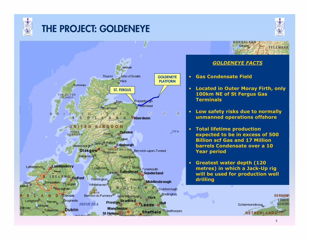
• Gas Condensate Field
• Located in Outer Moray Firth, only 100km NE of St Fergus Gas Terminals
• Low safety risks due to normally unmanned operations offshore
• Total lifetime production expected to be in excess of 500 Billion scf Gas and 17 Million barrels Condensate over a 10 Year period
• Greatest water depth (120 metres) in which a Jack-Up rig will be used for production well drilling
THE PROJECT: GOLDENEYE
Geomatics Foundation
2
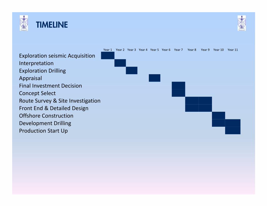
TIMELINE
Year 1 Year 2 Year 3 Year 4 Year 5 Year 6 Year 7 Year 8 Year 9 Year 10 Year 11
Exploration seismic Acquisition
Interpretation
Exploration Drilling
Appraisal
Final Investment Decision
Concept Select
Route Survey & Site Investigation
Front End & Detailed Design
Offshore Construction
Development Drilling
Production Start Up
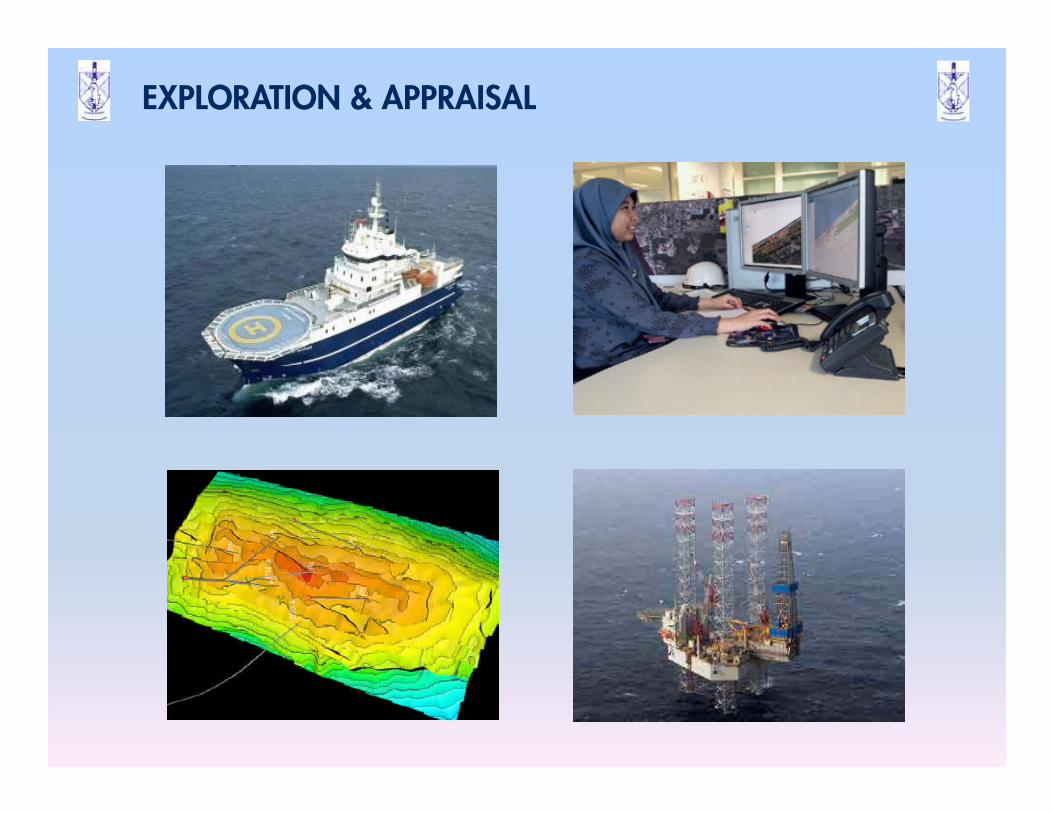
EXPLORATION & APPRAISAL
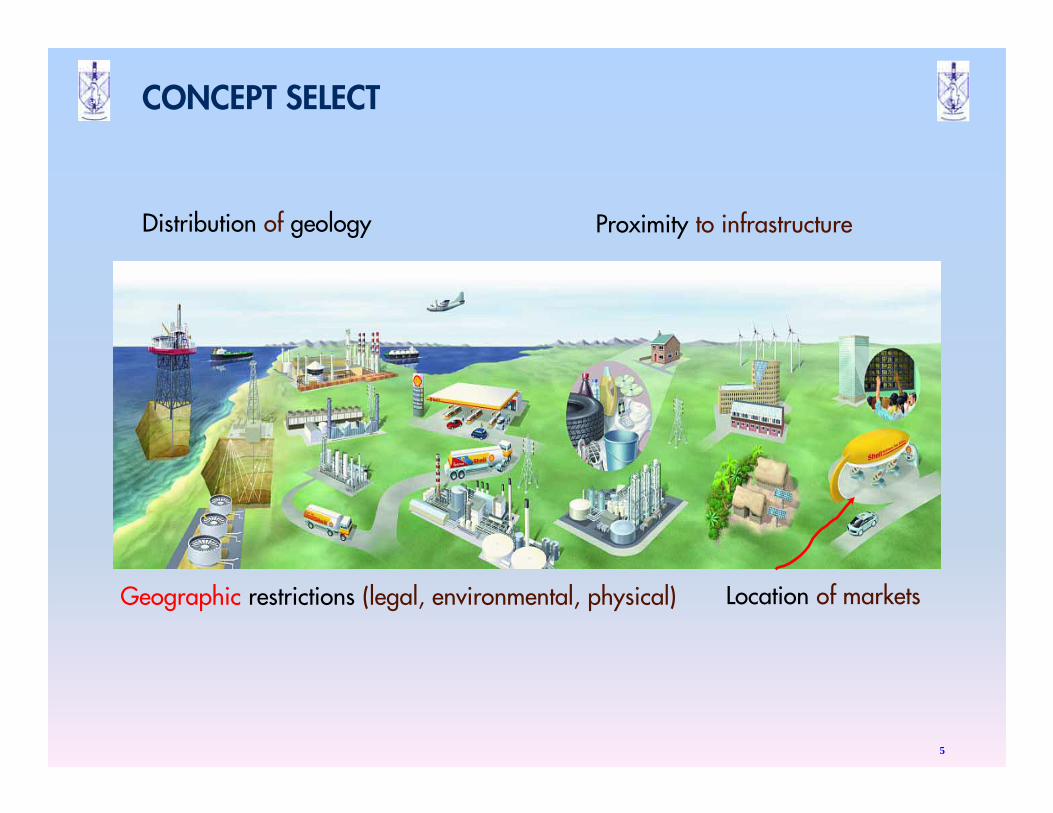
CONCEPT SELECT
5
Proximity to infrastructure
`
Location of marketsGeographic restrictions (legal, environmental, physical)
Distribution of geology
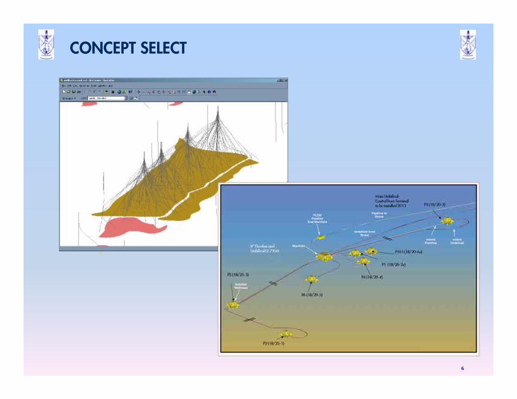
CONCEPT SELECT
6
`
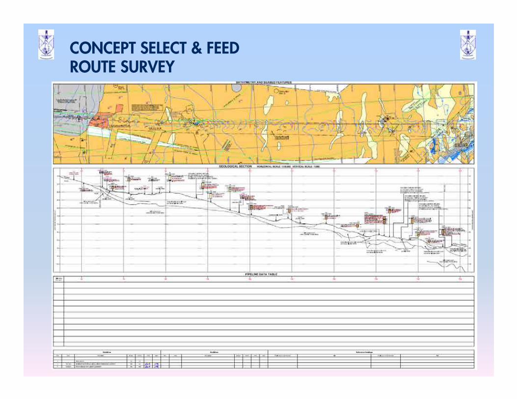
CONCEPT SELECT & FEEDROUTE SURVEY
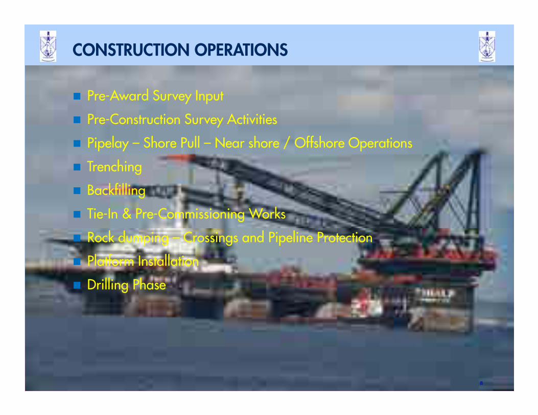
� Pre-Award Survey Input
� Pre-Construction Survey Activities
� Pipelay – Shore Pull – Near shore / Offshore Operations
� Trenching
� Backfilling
� Tie-In & Pre-Commissioning Works
� Rock dumping – Crossings and Pipeline Protection
� Platform Installation
� Drilling Phase
8
CONSTRUCTION OPERATIONS
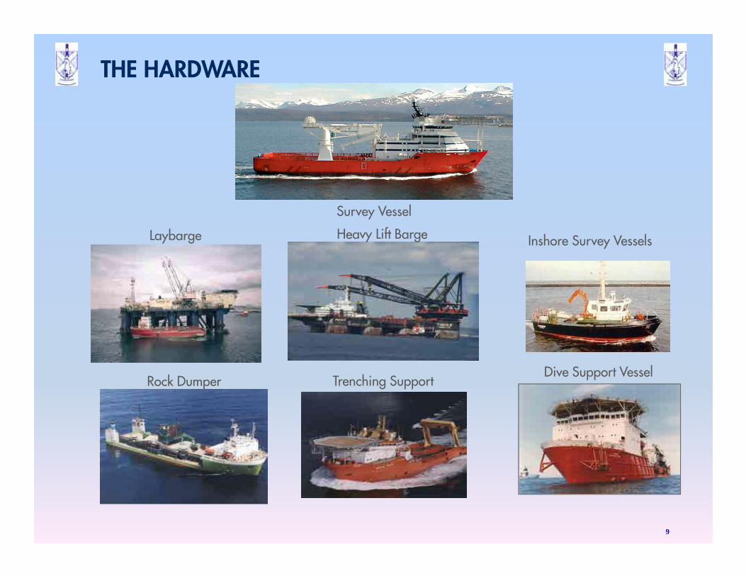
Laybarge Heavy Lift Barge
Rock Dumper Trenching Support
Survey Vessel
Inshore Survey Vessels
Dive Support Vessel
THE HARDWARE
9
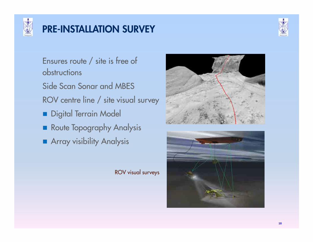
PRE-INSTALLATION SURVEY
Ensures route / site is free of
obstructions
Side Scan Sonar and MBES
ROV centre line / site visual survey
� Digital Terrain Model
� Route Topography Analysis
� Array visibility Analysis
10
ROV visual surveys
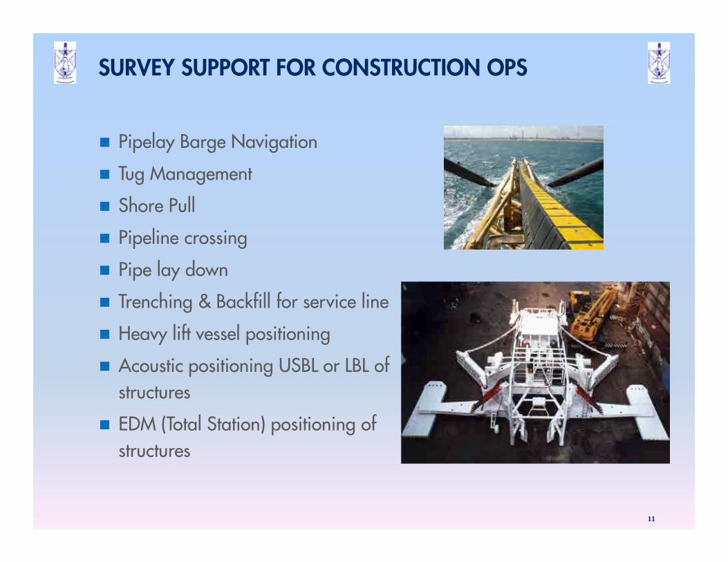
SURVEY SUPPORT FOR CONSTRUCTION OPS
� Pipelay Barge Navigation
� Tug Management
� Shore Pull
� Pipeline crossing
� Pipe lay down
� Trenching & Backfill for service line
� Heavy lift vessel positioning
� Acoustic positioning USBL or LBL of
structures
� EDM (Total Station) positioning of
structures
11
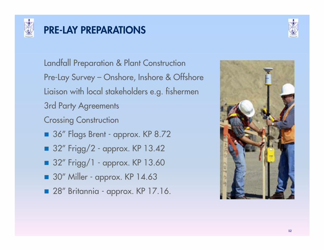
Landfall Preparation & Plant Construction
Pre-Lay Survey – Onshore, Inshore & Offshore
Liaison with local stakeholders e.g. fishermen
3rd Party Agreements
Crossing Construction
� 36” Flags Brent - approx. KP 8.72
� 32” Frigg/2 - approx. KP 13.42
� 32” Frigg/1 - approx. KP 13.60
� 30” Miller - approx. KP 14.63
� 28” Britannia - approx. KP 17.16.
12
PRE-LAY PREPARATIONS
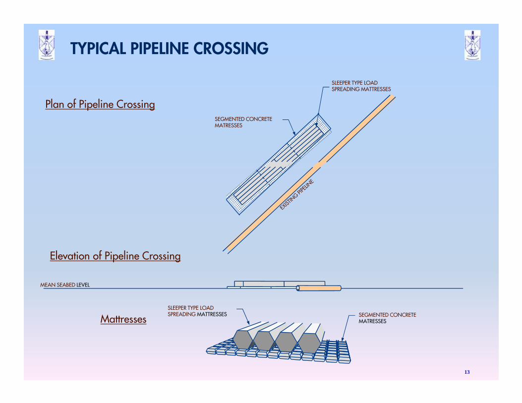
Elevation of Pipeline Crossing
Plan of Pipeline Crossing
MattressesSLEEPER TYPE LOADSPREADING MATTRESSES SEGMENTED CONCRETE
MATRESSES
SEGMENTED CONCRETEMATRESSES
SLEEPER TYPE LOADSPREADING MATTRESSES
MEAN SEABED LEVEL
TYPICAL PIPELINE CROSSING
13
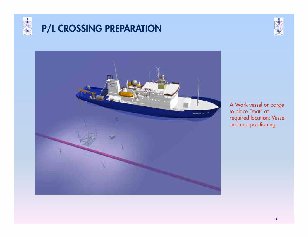
P/L CROSSING PREPARATION
14
A Work vessel or barge to place “mat” at required location: Vessel and mat positioning
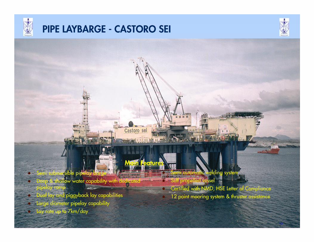
� Semi submersible pipelay barge
� Deep & shallow water capability with dedicated pipelay ramp
� Dual lay and piggyback lay capabilities
� Large diameter pipelay capability
� Lay rate up to 7km/day
� Semi automatic welding system
� Self propelled vessel
� Certified with NMD, HSE Letter of Compliance
� 12 point mooring system & thruster assistance
Main Features
PIPE LAYBARGE - CASTORO SEI
15
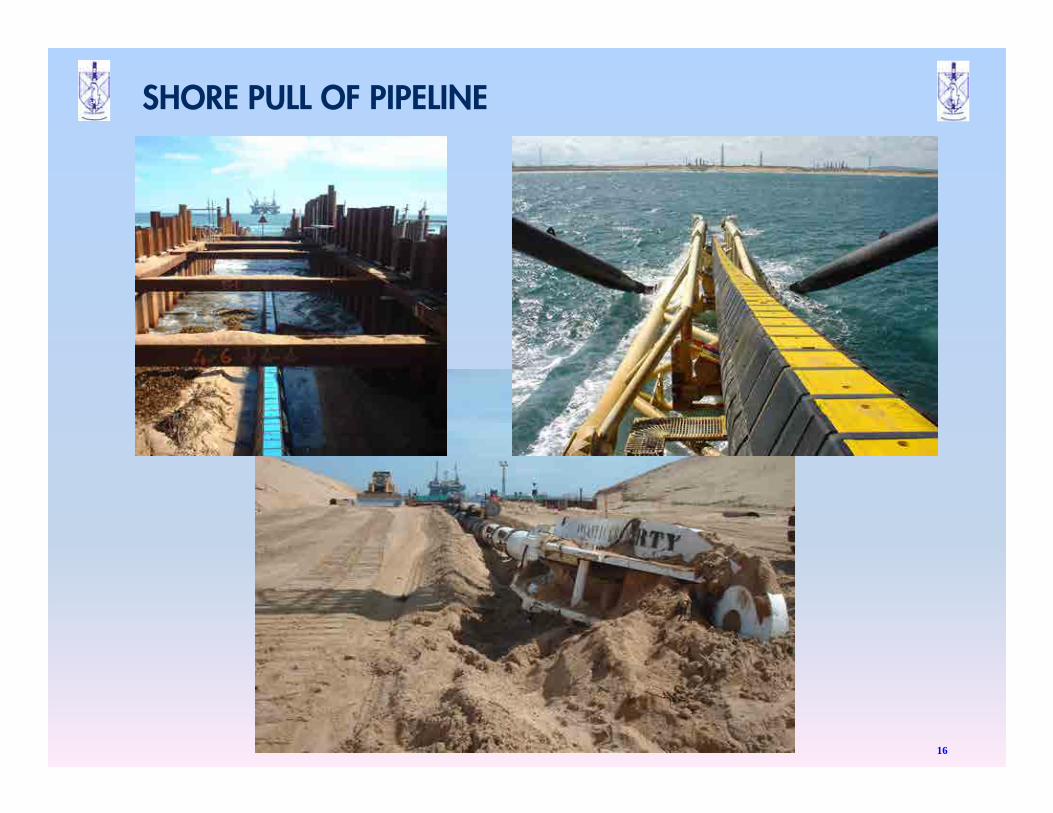
SHORE PULL OF PIPELINE
16
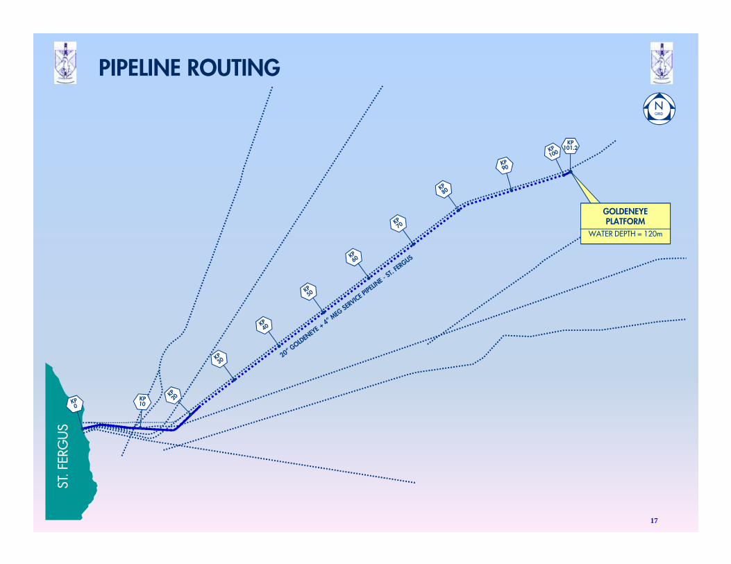
ST. F
ERG
US
KP101.2
GOLDENEYEPLATFORM
WATER DEPTH = 120m
17
PIPELINE ROUTING
ST. F
ERG
US
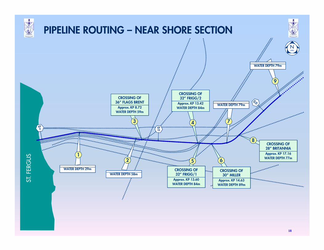
WATER DEPTH 79m
9
CROSSING OF28” BRITANNIAApprox. KP 17.16
WATER DEPTH 77m
8
WATER DEPTH 79m
7
CROSSING OF30” MILLER
Approx. KP 14.63WATER DEPTH 89m
6
CROSSING OF32” FRIGG/1
Approx. KP 13.60WATER DEPTH 84m
5
CROSSING OF32” FRIGG/2
Approx. KP 13.42WATER DEPTH 84m
4
CROSSING OF36” FLAGS BRENT
Approx. KP 8.72WATER DEPTH 59m
3
WATER DEPTH 58m
2
WATER DEPTH 29m
1
18
PIPELINE ROUTING – NEAR SHORE SECTION
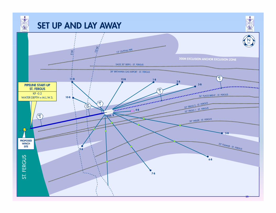
11-B 12-B 1-B2-B
3-B
5-B
6-B
7-B
9-B
10-B
4-B
PIPELINE START-UPST. FERGUS
KP -0.2WATER DEPTH = M.L.W.S.
ST. F
ERG
US
PROPOSEDWINCH
SITE
19
SET UP AND LAY AWAY
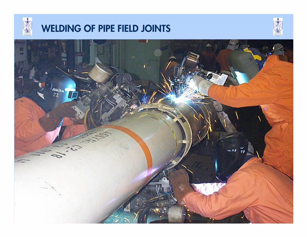
WELDING OF PIPE FIELD JOINTS
20
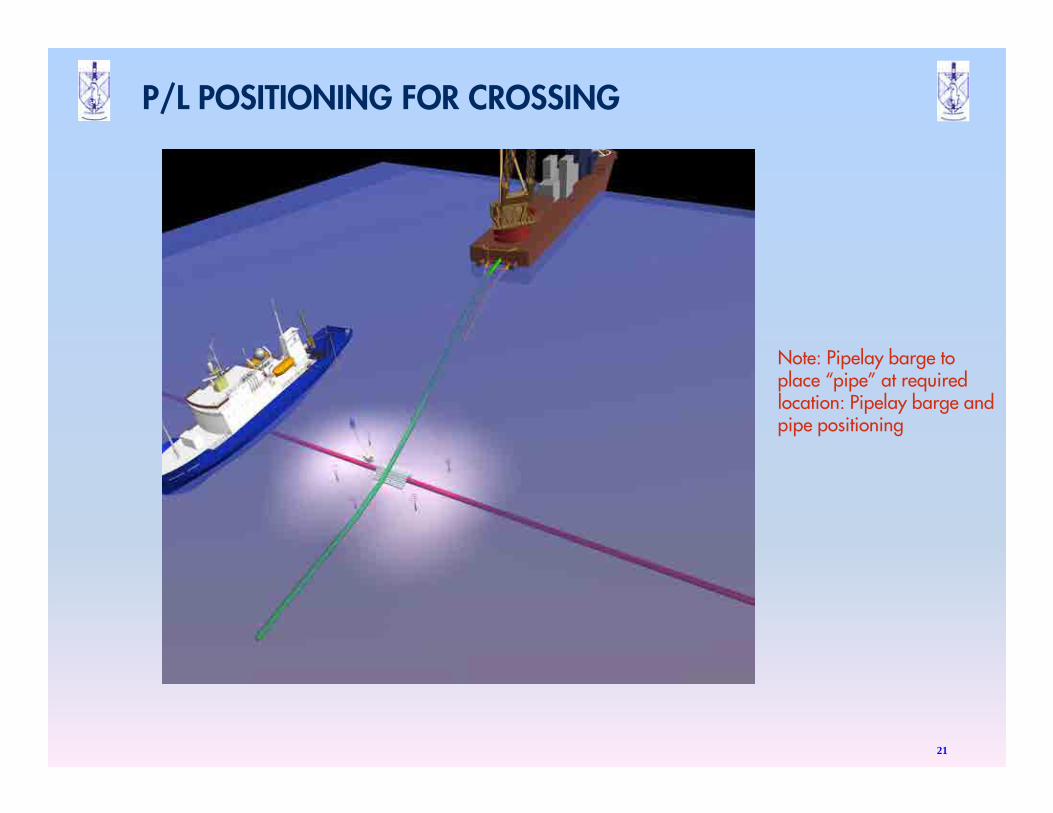
P/L POSITIONING FOR CROSSING
21
Note: Pipelay barge to place “pipe” at required location: Pipelay barge and pipe positioning
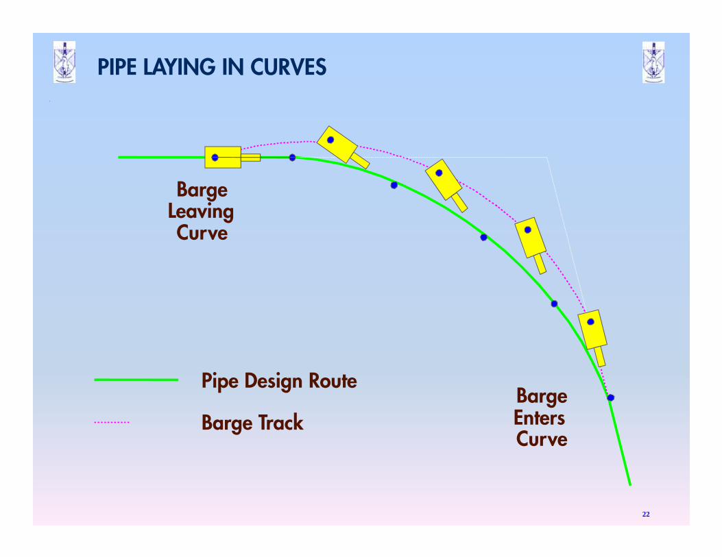
PIPE LAYING IN CURVES
22
Pipe Design Route
Barge Track
BargeLeavingCurve
BargeEntersCurve
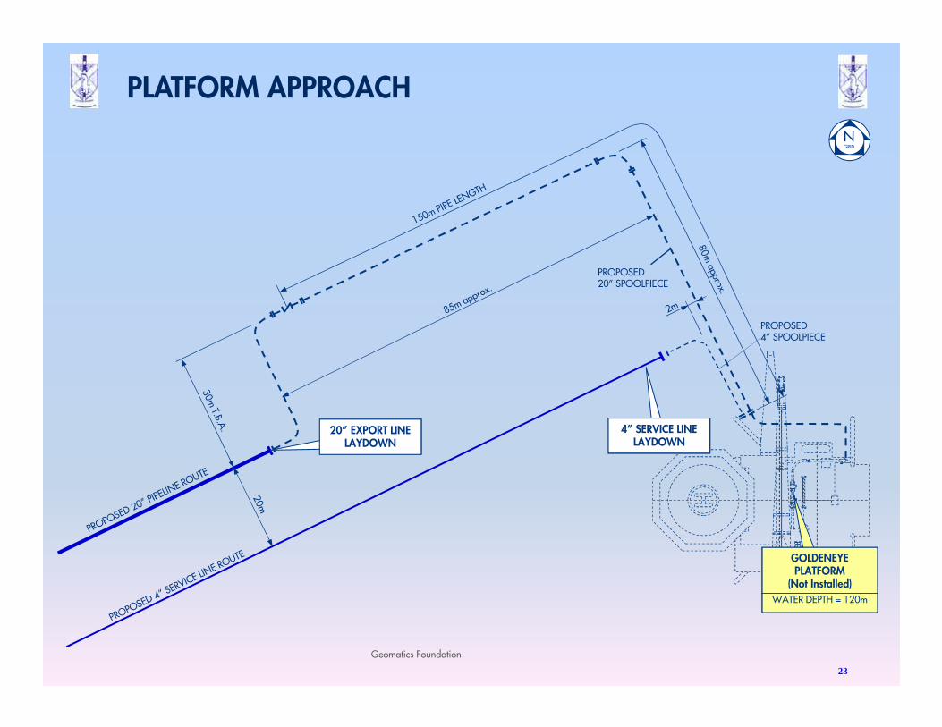
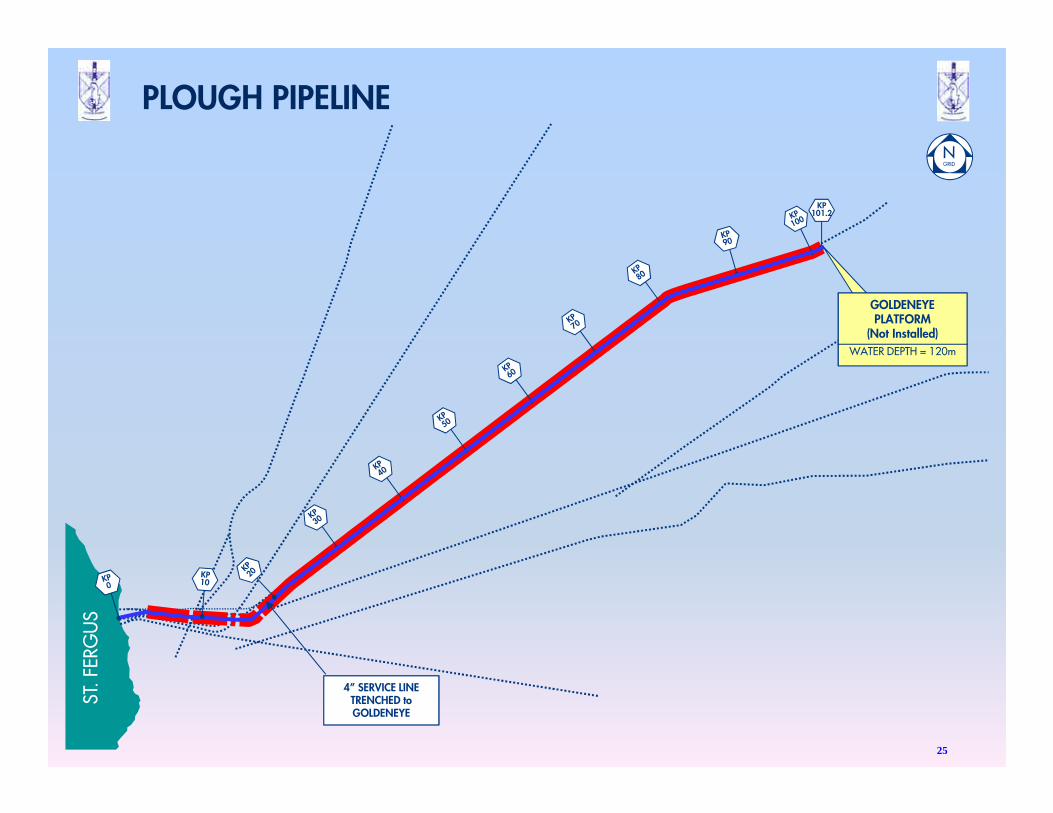
PROPOSED20” SPOOLPIECE
PROPOSED4” SPOOLPIECE
4” SERVICE LINE LAYDOWN
20” EXPORT LINELAYDOWN
GOLDENEYEPLATFORM
(Not Installed)
WATER DEPTH = 120m
Geomatics Foundation
23
PLATFORM APPROACH
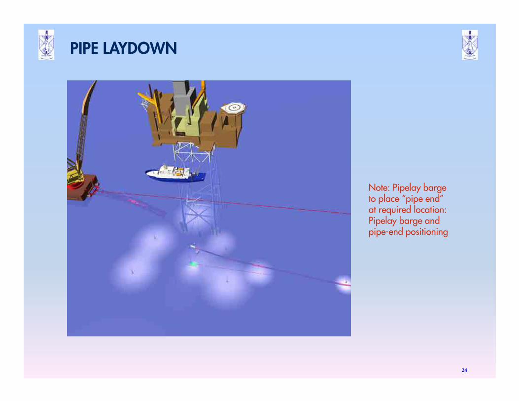
PIPE LAYDOWN
24
Note: Pipelay barge to place “pipe end” at required location: Pipelay barge and pipe-end positioning
ST. F
ERG
US
KP101.2
4” SERVICE LINETRENCHED to GOLDENEYE
GOLDENEYEPLATFORM
(Not Installed)
WATER DEPTH = 120m
25
PLOUGH PIPELINE
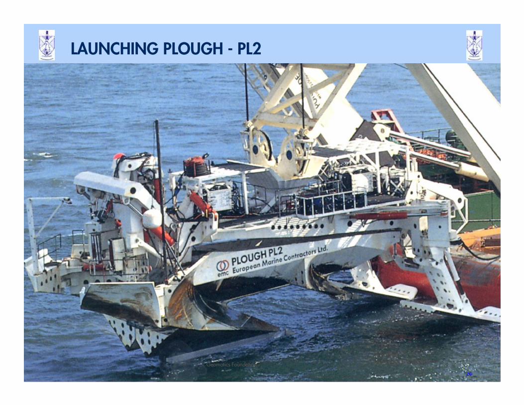
LAUNCHING PLOUGH - PL2
26
Geomatics Foundation
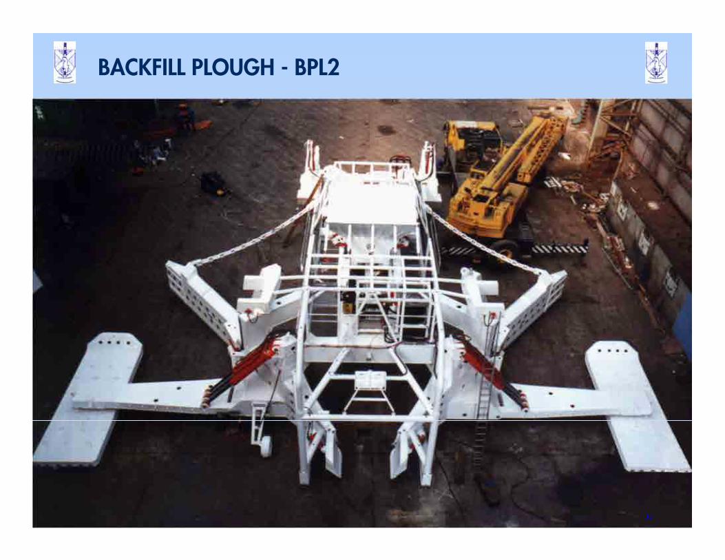
BACKFILL PLOUGH - BPL2
27
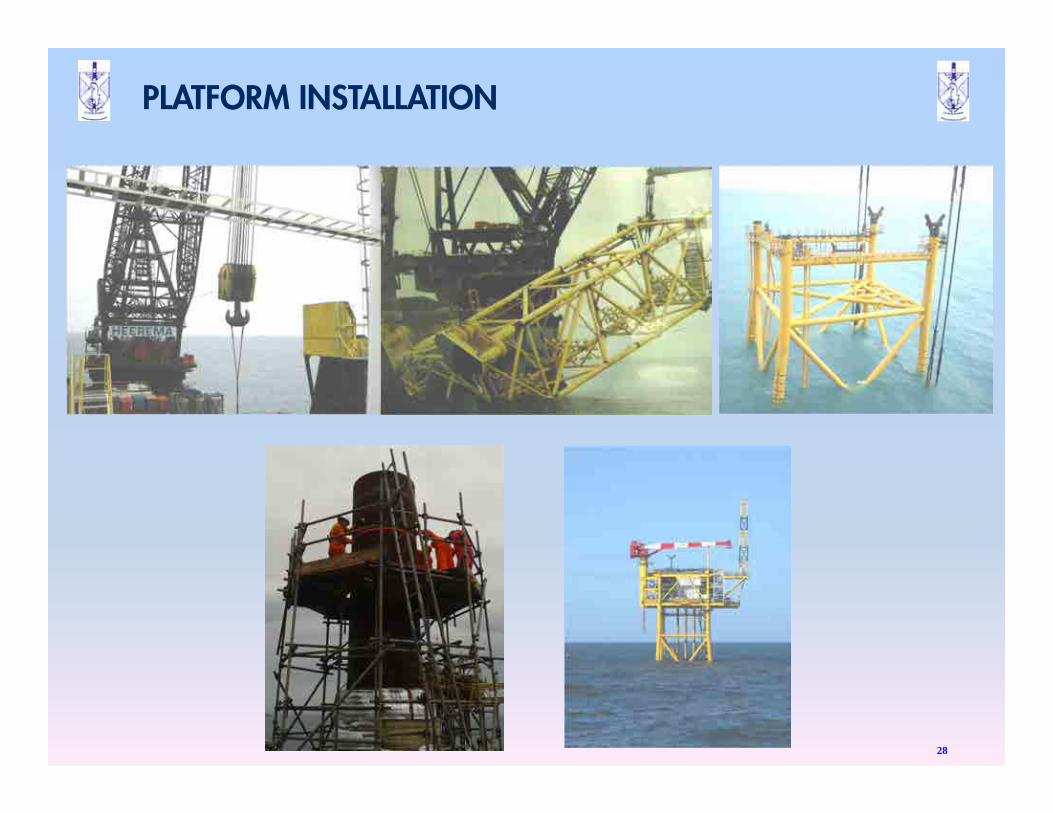
PLATFORM INSTALLATION
28
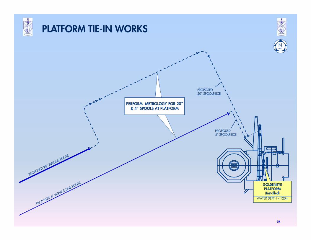
PROPOSED20” SPOOLPIECE
PROPOSED4” SPOOLPIECE
PERFORM METROLOGY FOR 20” & 4” SPOOLS AT PLATFORM
GOLDENEYEPLATFORM(Installed)
WATER DEPTH = 120m
29
PLATFORM TIE-IN WORKS
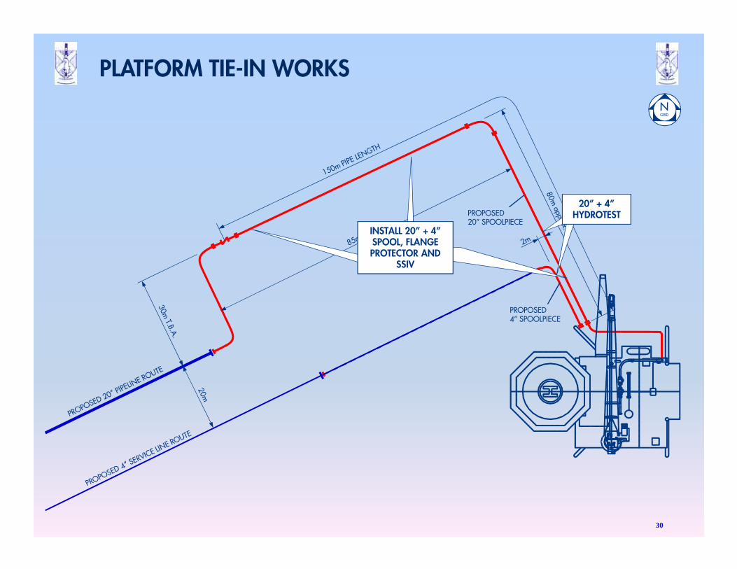
PROPOSED20” SPOOLPIECE
PROPOSED4” SPOOLPIECE
INSTALL 20” + 4” SPOOL, FLANGE PROTECTOR AND
SSIV
20” + 4”HYDROTEST
30
PLATFORM TIE-IN WORKS
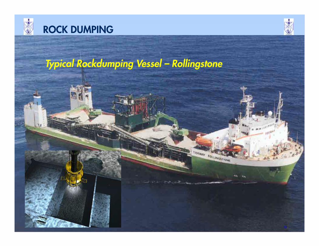
Typical Rockdumping Vessel – Rollingstone
31
ROCK DUMPING
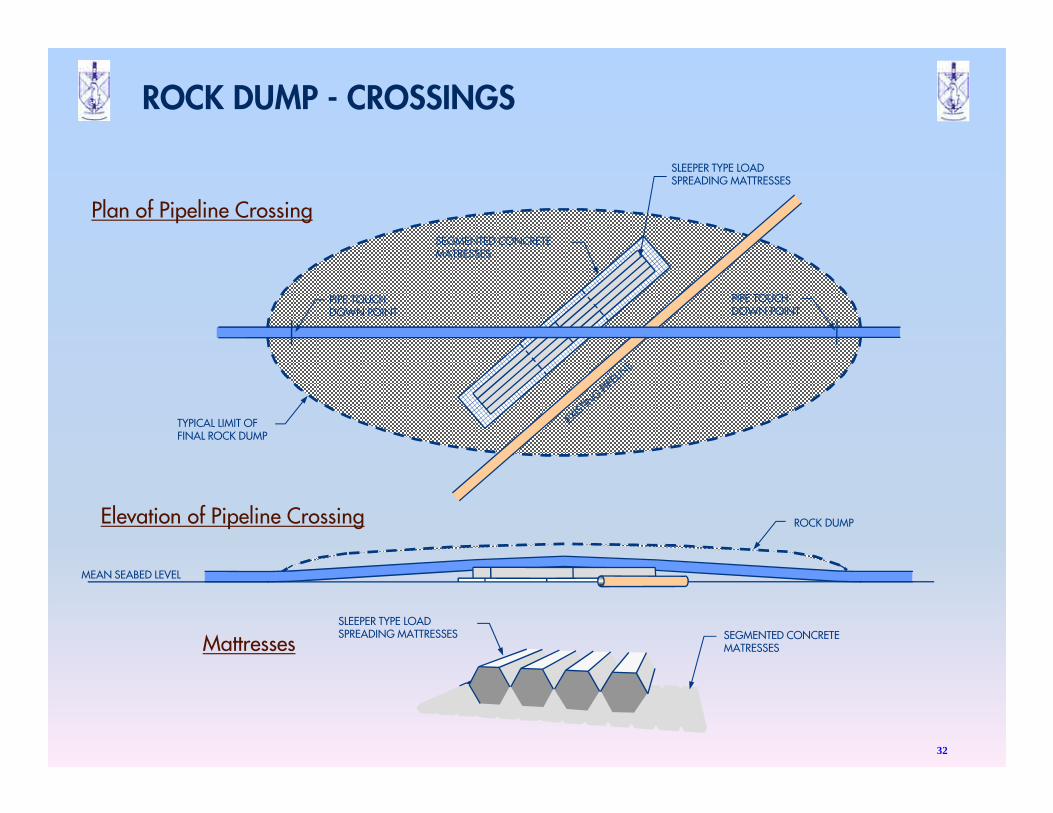
TYPICAL LIMIT OFFINAL ROCK DUMP
ROCK DUMP Elevation of Pipeline Crossing
Plan of Pipeline Crossing
MattressesSLEEPER TYPE LOADSPREADING MATTRESSES SEGMENTED CONCRETE
MATRESSES
PIPE TOUCHDOWN POINT
PIPE TOUCHDOWN POINT
SEGMENTED CONCRETEMATRESSES
SLEEPER TYPE LOADSPREADING MATTRESSES
MEAN SEABED LEVEL
32
ROCK DUMP - CROSSINGS
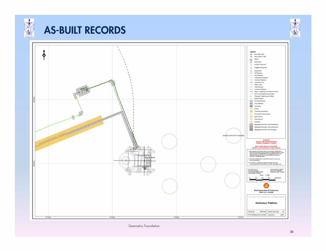
33
Geomatics Foundation
AS-BUILT RECORDS

Q + A
34