ofoverview of the rolls-royce so csofc technology … · ofoverview of the rolls-royce so csofc...
TRANSCRIPT
O f SO COverview of the Rolls-Royce SOFC Technology and SECA Program14th July 2009Richard GoettlerManager Fuel Cell Development
©2009 Rolls-Royce Fuel Cell Systems (US) Inc.
The information in this document is the property of Rolls-Royce Fuel Cell Systems (US) Inc. and may not be copied or communicated to a third party, or used for any purpose other than that for which it is supplied without the express written consent of Rolls-Royce Fuel Cell
Manager, Fuel Cell Development
p y, y p p pp p ySystems (US) Inc.
This information is given in good faith based upon the latest information available to Rolls-Royce Fuel Cell Systems (US) Inc. No warranty or representation is given concerning such information, which must not be taken as establishing any contractual or other commitment binding upon Rolls-Royce Fuel Cell Systems (US) Inc. or any of its subsidiary or associated companies.
This document does not contain any Export Controlled Data.
2
SECA Coal-Based Systems – Rolls Royce
TeamRRFCS(US) IRRFCS(US) Inc.RRFCS Ltd (UK)ORNLPNNLCase Western Reserve UniversityUniversity of ConnecticutUniversity of ConnecticutMatrix Innovations
Schedules:C l t 1500 h f 5000 h t k t t bComplete 1500 hrs of 5000 hour stack test by end-Sept. 2010
SECA Workshop 2009
Rolls-Royce data
3
HighlightsImprovement in cell ASRGreater rig availability for system relevant pressurized testingLower cost material sets Cycle chosen for the coal-based systemCycle chosen for the coal-based system System technology demonstrated at large scaleSECA plays critical role within RRFCS Programp y g
Supports next generation cell and stack developmentValidation of technology through system levelValidation of technology through system level block testing
SECA Workshop 2009
Rolls-Royce data
4
RRFCS Technology and SECA Program
Mission and organisationTechnology and approachStatus – Fuel Cell & StackLarge-scale system demonstrationSECA ProgramSECA ProgramNext steps & Conclusions
SECA Workshop 2009
Rolls-Royce data
5
Progress at Rolls-Royce Fuel Cell S t Li it dSystems Limited
Mission and organisationTechnology and approachTechnology and approachStatus – Fuel Cell & StackL l t d t tiLarge-scale system demonstrationSECA ProgramNext steps & Conclusions
SECA Workshop 2009
Rolls-Royce data

6
Rolls-Royce Energy Business
Trent 60 – 58MW
RB211 – 32MW
501 / Avon 5 – 14MW
Recips 1 2 8 5MWRecips 1.2 – 8.5MW
Fuel Cells 1MW Market Entry – follow on can be larger
Compressors – 37.3MW
SECA Workshop 2009
Rolls-Royce data

7
RRFCS is Developing MW-scale SOFC S t f Effi i t P G tiSystems for Efficient Power Generation
Pipeline natural
Fuel processing
gas
Airintake Fuel in
processing
ExhaustAir in
Power out
To grid
Turbomachinery Fuel cells
Controls
Near-term Market Opportunities for Distributed Energy
SECA Workshop 2009
Rolls-Royce data

8
RRFCS SOFC systems combined for t li d ti
Storage
2018 and beyond
centralized power generation
ResidentialIndustrial
yRenewablesFuel Cell
Commercial >100 MWAdvanced IGFC
FC Expo 2009
SECA Workshop 2009
Rolls-Royce data
FC Expo 2009
9
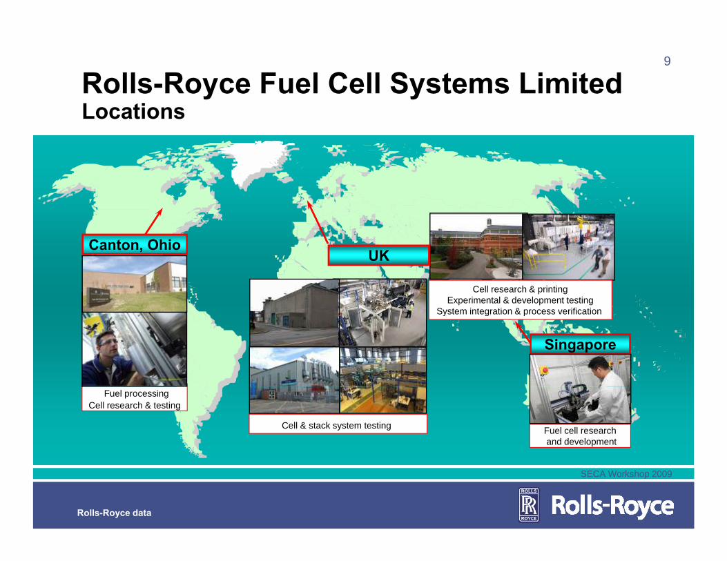
Rolls-Royce Fuel Cell Systems LimitedL tiLocations
Canton OhioUK
Cell research & printingExperimental & development testing
System integration & process verification
Canton, Ohio
Singapore
y g p
Cell & stack system testing Fuel cell researchand development
Fuel processingCell research & testing
SECA Workshop 2009
Rolls-Royce data

10
Progress at Rolls-Royce Fuel Cell S t Li it dSystems Limited
Mission and organisationTechnology and approachTechnology and approachStatus of Fuel Cell & StackL l t d t tiLarge-scale system demonstrationSECA ProgramNext steps & Conclusions
SECA Workshop 2009
Rolls-Royce data

11Rolls-Royce integrated planar solid oxide fuel cell
In-plane current collector Air CathodePrimary Interconnect
Porous substrate
YSZ
Fuel
Anode
Cell/Substrate barrier
Integrated planar series arrangementSeries connected cell design for high voltage low currentThin layers of active materials minimize cost
Fuel
Thin layers of active materials minimize costCeramic support material uses low cost MgO+Al2O3 powder +
low cost extrusionCathode + current collector
High voltage low current benefits
Easier hence cheaper for power electronics to convert low current DC to AC
YSZ
barrier
current collectorAnode
current DC to AC
High voltage facilitate direct conversion to 480 V AC grid requirement
Low currents give low Ohmic I2R losses offering greater materials options
substrate
SECA Workshop 2009
Rolls-Royce data
materials options

12
Low Cost Manufacturing ProcessesPrint/Dry Line
Tunnel Furnace
Glassing Area from the Process Verification Line
SECA Workshop 2009
Rolls-Royce data
13
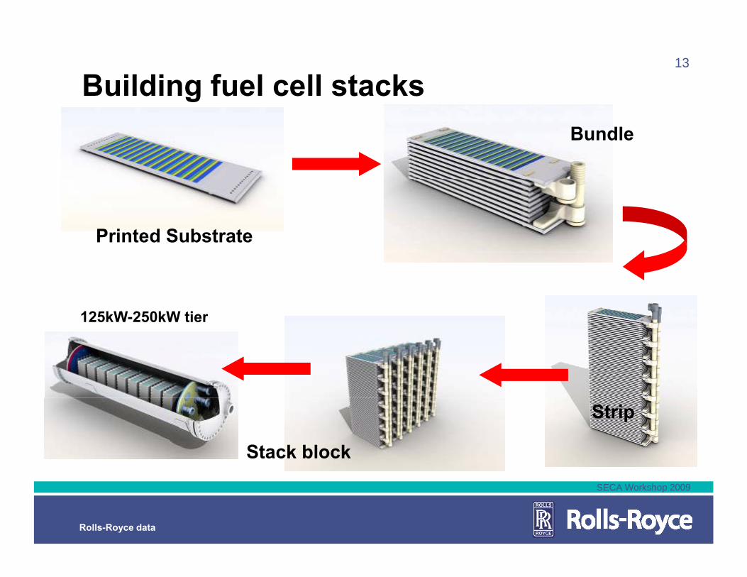
Building fuel cell stacksBundle
Printed Substrate
125kW-250kW tier
Stack block
Strip
SECA Workshop 2009
Rolls-Royce data
14
Progress at Rolls-Royce Fuel Cell S t Li it dSystems Limited
Mission and organisationTechnology and approachTechnology and approachStatus – Fuel Cell & StackL l t d t tiLarge-scale system demonstrationSECA ProgramNext steps & Conclusions
SECA Workshop 2009
Rolls-Royce data

15
Progress to date on de-risking cost d bilit d li bilitdurability and reliability
500
400 0
Watt per tubeDurability / hourPart count per kW
1k
2
102
42k
00
3020
k8k
100
4050
50
16k
60
2008200620042002
EIS capable
SECA Workshop 2009
Rolls-Royce data

16
Pressurised bundle performanceSix substrate bundle operated at 2.5 bar60 300
Substrate 1 is fuel inlet and Substrate 6 fuel exit
55
200
250
W
Tube 6 Power Tube 5 Power Tube 4 Power Tube 3 PowerTube 2 Power W
Substrate 2 PowerSubstrate 3 PowerSubstrate 4 PowerSubstrate 5 Power
Substrate 1 Power
r/W
Power measured at constant current (1.8 A) for the bundle data45
50
100
150
Tube
Pow
er / Tube 2 Power
Tube 1 Power Bundle Power
undl
e Po
wer
/ WSubstrate 5 Power
Substrate 6 Power
ubst
rate
Pow
er
Unplanned shutdown (site related) at 2444 hours resulted in
d f d d35
40
0
50
100
BuSu
redox of anodes and significant change in degradation rate
0 500 1000 1500 2000 2500 3000 3500 400035 0
Time / h
SECA Workshop 2009
Rolls-Royce data

17
Single-Substrate durability demonstrated t 6000 h
40.00
to 6000 hr
30.00
35.00
T0837, Atmospheric, inlet reformate, 900C, 6000 hours
20.00
25.00
Pow
er /
W
WRD2118-455WRD2118-466
,
10.00
15.00 WRD2118-468WRD2118-469WRD2118-470
Degradation % per 1000 hours;Tube2 1.9
0.00
5.00
0 1000 2000 3000 4000 5000 6000 7000
Time / Hours
Tube3 1.1Tube4 0.75Tube5 0.82
SECA Workshop 2009
Rolls-Royce data
Time / Hours
18
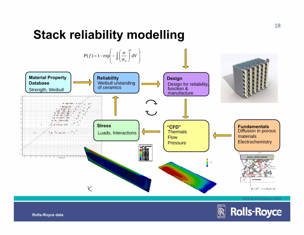
Stack reliability modelling⎟⎟
⎠
⎞
⎜⎜
⎝
⎛⎟⎟⎠
⎞⎜⎜⎝
⎛−−= ∫ dVfP
V
m
0
exp1)(σσ
ReliabilityWeibull u/standing of ceramics
Material Property DatabaseStrength, Weibull
DesignDesign for reliability, function & manufacture
StressLoads Interactions
FundamentalsDiffusion in porous
“CFD”ThermalsLoads, Interactions p
materialsElectrochemistry
ThermalsFlowPressure
H2
e-
H2OH2
e-
H2O
O2-
−− +⎯→⎯+ eOHOH 222
2
SOFCAnode
O2-
−− +⎯→⎯+ eOHOH 222
2
SOFCAnode
Electroniccurrent
Ioniccurrent
SECA Workshop 2009
Rolls-Royce data

19
Progress at Rolls-Royce Fuel Cell S t Li it dSystems Limited
Mission and organisationTechnology and approachTechnology and approachStatus – Fuel Cell & StackL l t d t tiLarge-scale system demonstrationSECA ProgramNext steps & Conclusions
SECA Workshop 2009
Rolls-Royce data
20
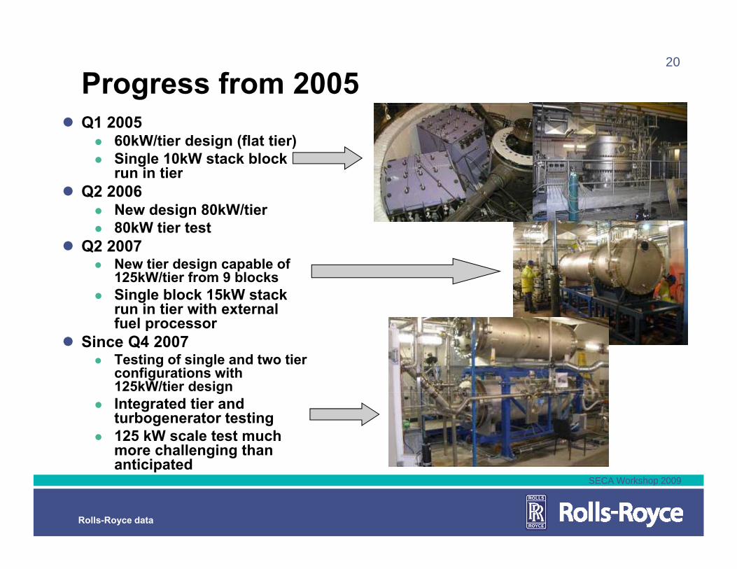
Progress from 2005Q1 2005
60kW/tier design (flat tier)Single 10kW stack block run in tierrun in tier
Q2 2006New design 80kW/tier80kW tier test
Q2 2007Q2 2007New tier design capable of 125kW/tier from 9 blocksSingle block 15kW stack run in tier with external fuel processorfuel processor
Since Q4 2007Testing of single and two tier configurations with 125kW/tier designgIntegrated tier and turbogenerator testing125 kW scale test much more challenging than anticipated
SECA Workshop 2009
Rolls-Royce data
anticipated
21
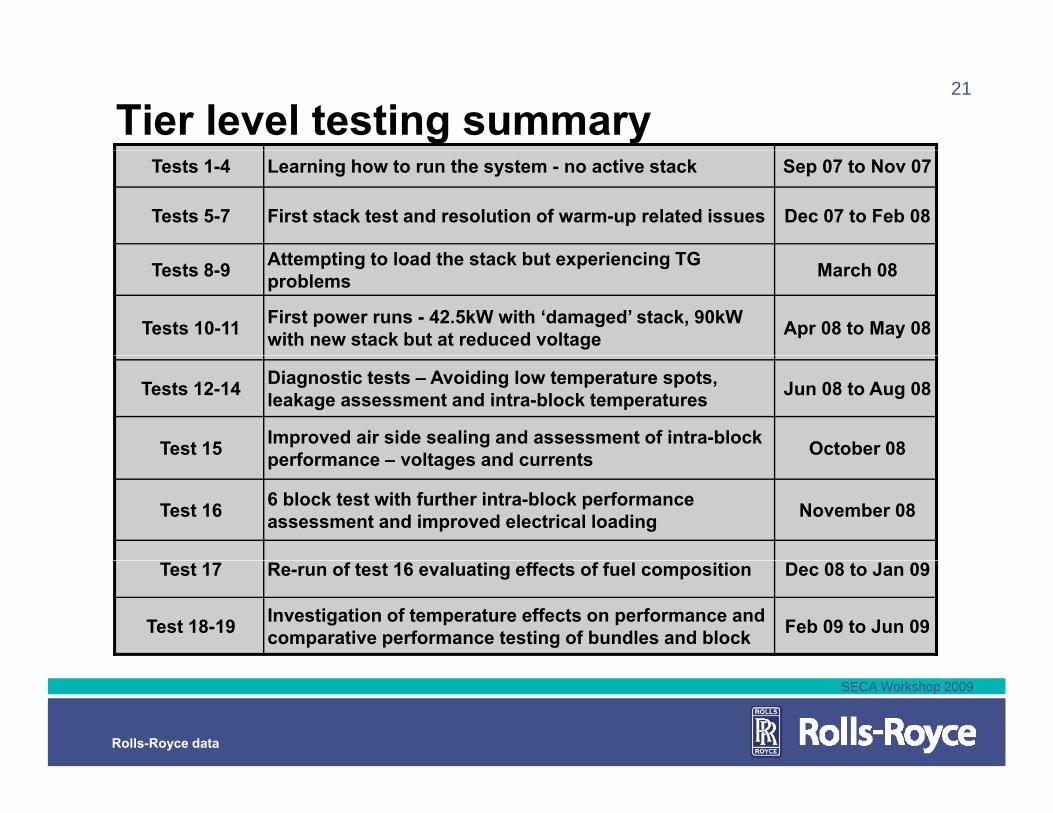
Tier level testing summaryTests 1-4 Learning how to run the system - no active stack Sep 07 to Nov 07
Tests 5-7 First stack test and resolution of warm-up related issues Dec 07 to Feb 08
Att ti t l d th t k b t i i TGTests 8-9 Attempting to load the stack but experiencing TG problems March 08
Tests 10-11 First power runs - 42.5kW with ‘damaged’ stack, 90kW with new stack but at reduced voltage Apr 08 to May 08
Tests 12-14 Diagnostic tests – Avoiding low temperature spots, leakage assessment and intra-block temperatures Jun 08 to Aug 08
Test 15 Improved air side sealing and assessment of intra-block performance voltages and currents October 08performance – voltages and currents
Test 16 6 block test with further intra-block performance assessment and improved electrical loading November 08
Test 17 Re-run of test 16 evaluating effects of fuel composition Dec 08 to Jan 09
Test 18-19 Investigation of temperature effects on performance and comparative performance testing of bundles and block Feb 09 to Jun 09
SECA Workshop 2009
Rolls-Royce data
22
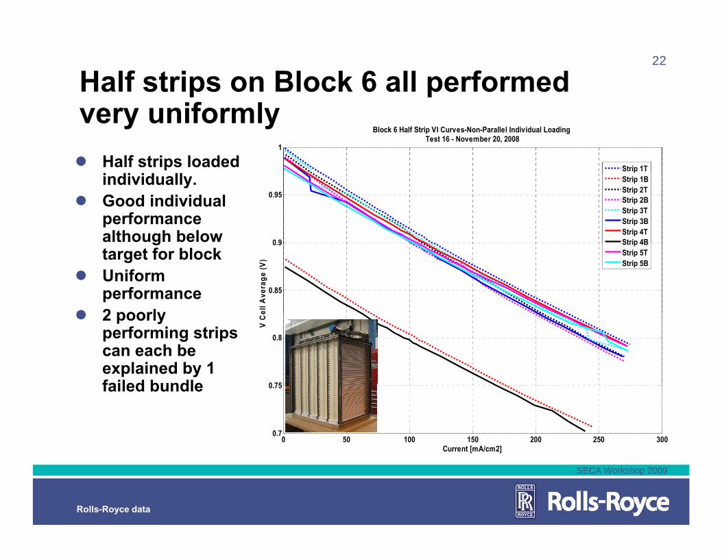
Half strips on Block 6 all performed if lvery uniformly
Half strips loaded i di id ll
1
Block 6 Half Strip VI Curves-Non-Parallel Individual Loading Test 16 - November 20, 2008
Strip 1Tindividually.Good individual performance although below 0 9
0.95
Strip 1BStrip 2TStrip 2BStrip 3TStrip 3BStrip 4TStrip 4Bg
target for blockUniform performance2 poorly
0.85
0.9
ell A
vera
ge (V
)
Strip 4BStrip 5TStrip 5B
2 poorly performing strips can each be explained by 1 failed bundle 0 75
0.8
V C
e
failed bundle
0 50 100 150 200 250 3000.7
0.75
Current [mA/cm2]
SECA Workshop 2009
Rolls-Royce data
23
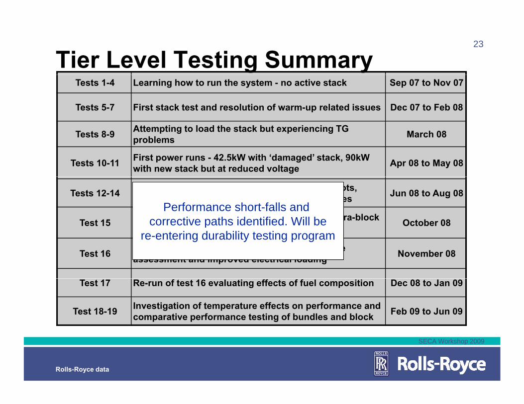
Tier Level Testing SummaryTests 1-4 Learning how to run the system - no active stack Sep 07 to Nov 07
Tests 5-7 First stack test and resolution of warm-up related issues Dec 07 to Feb 08
Att ti t l d th t k b t i i TGTests 8-9 Attempting to load the stack but experiencing TG problems March 08
Tests 10-11 First power runs - 42.5kW with ‘damaged’ stack, 90kW with new stack but at reduced voltage Apr 08 to May 08
Tests 12-14 Diagnostic tests – Avoiding low temperature spots, leakage assessment and intra-block temperatures Jun 08 to Aug 08
Test 15 Improved air side sealing and assessment of intra-block performance voltages and currents October 08
Performance short-falls and corrective paths identified. Will beperformance – voltages and currents
Test 16 6 block test with further intra-block performance assessment and improved electrical loading November 08
pre-entering durability testing program
Test 17 Re-run of test 16 evaluating effects of fuel composition Dec 08 to Jan 09
Test 18-19 Investigation of temperature effects on performance and comparative performance testing of bundles and block Feb 09 to Jun 09
SECA Workshop 2009
Rolls-Royce data

24
RRFCS Sub-System StatusStart Gas system• Factory pass-off testing completed
1MW Desulfurizer• Factory pass-off test complete y p p• DOE durability program (8000 hrs)
Turbogenerator• Full system integration tests• Full system integration tests
Power ElectronicsSystem Packaging• Established for 1MW field demonstrations
SECA Workshop 2009
Rolls-Royce data
• Completed 3-yr DOE funded demo program at Next Energy with On-Power
25
Progress at Rolls-Royce Fuel Cell S t Li it dSystems Limited
Mission and organisationTechnology and approachTechnology and approachProgress to date – Fuel Cell & StackL l t d t tiLarge-scale system demonstrationSECA ProgramNext steps & Conclusions
SECA Workshop 2009
Rolls-Royce data
26
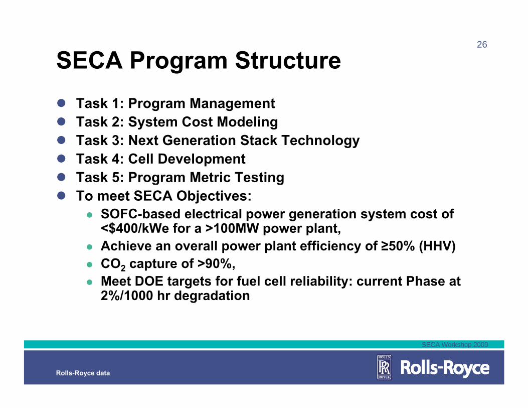
SECA Program StructureTask 1: Program ManagementTask 2: System Cost Modelingy gTask 3: Next Generation Stack TechnologyTask 4: Cell DevelopmentTask 5: Program Metric TestingTask 5: Program Metric TestingTo meet SECA Objectives:
SOFC-based electrical power generation system cost of <$400/kWe for a >100MW power plant<$400/kWe for a >100MW power plant, Achieve an overall power plant efficiency of ≥50% (HHV)CO2 capture of >90%,Meet DOE targets for fuel cell reliability: current Phase atMeet DOE targets for fuel cell reliability: current Phase at 2%/1000 hr degradation
SECA Workshop 2009
Rolls-Royce data

27
Task 2: Modeling of High Efficiency C t l ti C l G ifi tiCatalytic Coal Gasification
Plant Operations SequenceCoal Gasifier (700C exit) Property DOE SECA Input
Aspen Simulation, 5% carbon loss
Mole Frac
Syngas Composition
Primary Cyclone / Secondary (barrier) Pt. FiltersSteam super-heatWarm-gas desulfurization (425C to 525C)
C2H6 0 0CH4 0.18 0.180CO 0.05 0.048
CO2 0.22 0.200H2 0.16 0.155
H2O 0.38 0.414N2 0.01 0.003O2 0 0525C)
Barrier Pt. Filter 2Re-heat Heat Exchanger, hot-sideTrace Metals Sorbents and Sulfur Guard Bed
O2 0 0Sum 1.00 1.000
Flow, g/s 52.07 51.26MW 21.42 20.90Flow, gmole/s 2.43 2.45kWthermal(HHV), Coal unknown 566kWthermal(HHV) 535 536Guard Bed
Re-heat Heat Exchanger, cold-sideTurbine expandersF.C Power Plant
Coal-syngas provides similar stack
thermal( )Cold Gas Eff. unknown 94.6kWthermal(LHV) 480 480
PropertyReformed Coal-
SyngasMole Frac
C2H6
Stack Inlet Fuel Composition
Coal-syngas provides similar stack inlet fuel composition as natural gas cycle
C2H6CH4 0.030CO 0.179
CO2 0.124H2 0.419
H2O 0.244N2 0.003O2 0.000
SECA Workshop 2009
Rolls-Royce data
Sum 1.00

28
Selected SOFC cycle for IGFC PlantRequires separate air and fuel streams for CO2 captureOGB
Baseline NG Cycle
Without OGB to balance reforming endotherm, reformer removed from cathode loop
Fuel CellCathode
Fuel CellAnode
REFORMER
Anode EjectorNG
Cathode EjectorTurbo-Generator
pAnode recycle eliminated given dilute coal-syngas fuel
Coal-Derived Synthesis Gas Cycle
Operation at peak SOFC T=900C, 6 bara, Uf=79% yields 50% IGFC efficiencyFor SECA block test coal
Fuel CellCathode
Fuel CellAnode
REFORME
Cathode Ejector
Coal-Derived Synthesis Gas
Turbo-Generator
For SECA block test, coal-syngas supplied via CPOX reforming
R
N2-FreeOff-Gas Burner
Condenser
H2O
O2
CO2 Sequestration
Ejector 2
SECA Workshop 2009
Rolls-Royce data
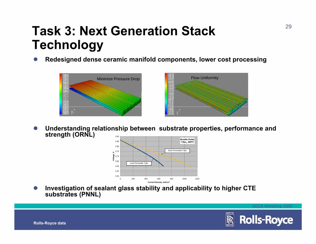
29Task 3: Next Generation Stack TechnologyTechnology
Redesigned dense ceramic manifold components, lower cost processing
Minimize Pressure Drop Flow Uniformity
0.90
Understanding relationship between substrate properties, performance and strength (ORNL)
Bundle Outlet 1 Bara, 900ºC
0.60
0.65
0.70
0.75
0.80
0.85
Volta
ge, V
Less Permeable Tube
More Permeable Tube
g ( )
0.50
0.55
0 200 400 600 800 1000 1200
Current Density, mA/cm2
SCT6-26A PCT21AInvestigation of sealant glass stability and applicability to higher CTE substrates (PNNL)
SECA Workshop 2009
Rolls-Royce data
30
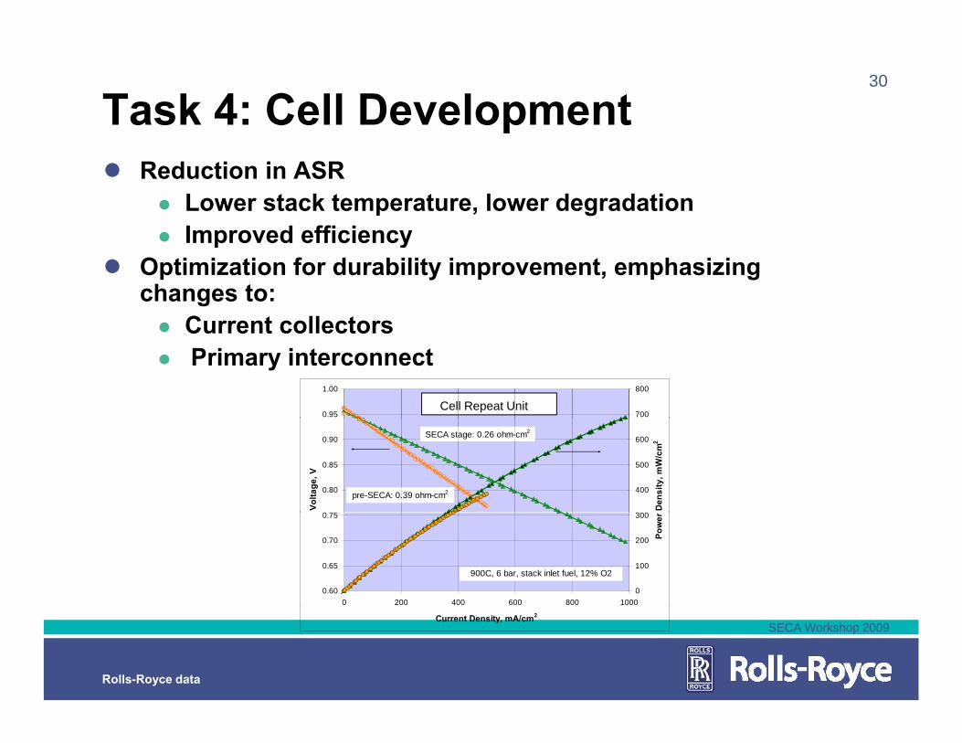
Task 4: Cell DevelopmentReduction in ASR
Lower stack temperature, lower degradationImproved efficiencyImproved efficiency
Optimization for durability improvement, emphasizing changes to:
Current collectorsCurrent collectorsPrimary interconnect
0.95
1.00
700
800
Cell Repeat Unit
0.80
0.85
0.90
Volta
ge, V
400
500
600
Den
sity
, mW
/cm
2
pre-SECA: 0.39 ohm-cm2
SECA stage: 0.26 ohm-cm2
0.60
0.65
0.70
0.75
0 200 400 600 800 10000
100
200
300
Pow
er
900C, 6 bar, stack inlet fuel, 12% O2
SECA Workshop 2009
Rolls-Royce data
Current Density, mA/cm2
31
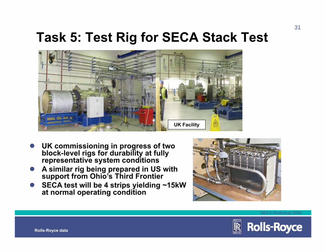
Task 5: Test Rig for SECA Stack Test
UK Facility
UK commissioning in progress of two block-level rigs for durability at fully representative system conditionsA similar rig being prepared in US with
t f Ohi ’ Thi d F tisupport from Ohio’s Third FrontierSECA test will be 4 strips yielding ~15kW at normal operating condition
SECA Workshop 2009
Rolls-Royce data
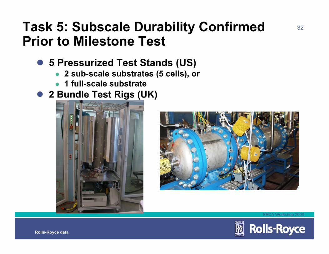
32Task 5: Subscale Durability Confirmed Prior to Milestone Test
5 Pressurized Test Stands (US)2 sub-scale substrates (5 cells), or1 full-scale substrate
2 Bundle Test Rigs (UK)
SECA Workshop 2009
Rolls-Royce data
Mar Apr May Jun Jul Aug Sep Oct Nov Dec Jan Feb Mar Apr May Jun Jul Aug Sep2009 2010
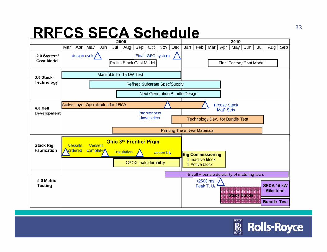
33RRFCS SECA Schedule2.0 System/Cost Model
3.0 Stack
Mar Apr May Jun Jul Aug Sep Oct Nov Dec Jan Feb Mar Apr May Jun Jul Aug Sep
design cycle
Manifolds for 15 kW Test
Prelim Stack Cost Model
Final IGFC system
Final Factory Cost Model
3.0 StackTechnology
4.0 Cell
Refined Substrate Spec/Supply
Next Generation Bundle Design
Active Layer Optimization for 15kW Freeze StackMat’l Sets
Development
Ohio 3rd Frontier Prgm
Technology Dev. for Bundle TestInterconnect downselect
Mat l Sets
Printing Trials New Materials
Stack RigFabrication
Vessels ordered
Vessels completed
Ohio 3 Frontier Prgm
insulation
CPOX trials/durability
5 cell + bundle durability of maturing tech
Rig Commissioning1 Inactive block1 Active block
assembly
5.0 MetricTesting
5-cell + bundle durability of maturing tech.
SECA 15 kWMilestone
Bundle Test
>2500 hrsPeak T, Uf
Stack Builds

34
SummarySignificant progress (pre-SECA) has been made in many areas
Maturing of the Stack TechnologyMaturing of the Stack TechnologySystem integration at large scaleSub-system design and testingSSystem testing, understanding and modelling
Top remaining technology challenges:Confirming durability of the fuel cellg ySystem demonstration testing
SECA plays critical role within RRFCS ProgramSupports next generation cell and stackSupports next generation cell and stack developmentValidation of technology through system level block testing
SECA Workshop 2009
Rolls-Royce data
block testing
35
AcknowledgementsThis material is based on work supported by the Dept. of Energy National Energy Technology Laboratory under Award Number DE-FC26-08NT0003893RRFCS j t T i Sh lt d thRRFCS project manager Travis Shultz and the entire SECA program management team UK and US based RRFCS teamUK and US based RRFCS teamRRFCS SECA partners
This report was prepared as an account of work sponsored b an agency of the United States Government. Neither the United States Governmentnor any agency thereof, nor any of their employees, makes any warranty, express or implied, or assumes any legal liability or responsibility for theaccuracy, completeness, or usefulness of any information, apparatus, product, or process disclosed, or represents that its use would not infringeprivately owned rights. Reference herein to any specific commercial product, process, or service by trade name, trademark, manufacturer, or otherwisedoes not necessarily contituite or imply its endorsement, recommendation, or favoring of the United States Government or any agency thereof. The views and opinions of authors expressed herein do not necessarily state or reflect those of the United States Government or any agency thereof.
SECA Workshop 2009
Rolls-Royce data
Thank youOverview of the Rolls-Royce SOFC Technology and SECA ProgramTechnology and SECA ProgramJuly 14th, 2009Richard Goettler
©2009 Rolls-Royce Fuel Cell Systems (US) Inc.
The information in this document is the property of Rolls-Royce Fuel Cell Systems (US) Inc. and may not be copied or communicated to a third party, or used for any purpose other than that for which it is supplied without the express written consent of Rolls-Royce Fuel Cell p y, y p p pp p ySystems (US) Inc.
This information is given in good faith based upon the latest information available to Rolls-Royce Fuel Cell Systems (US) Inc. No warranty or representation is given concerning such information, which must not be taken as establishing any contractual or other commitment binding upon Rolls-Royce Fuel Cell Systems (US) Inc. or any of its subsidiary or associated companies.
This document does not contain any Export Controlled Data.