og10333-l behind the face tips and tricks in autocad plant 3d - autodesk€¦ · behind the face...
TRANSCRIPT
Behind the Face – Tips and Tricks in AutoCAD Plant 3D
1
OG10333-L
Behind the Face—Tips and Tricks in AutoCAD Plant 3D Bernd Gerstenberger Autodesk Learning Objectives
Discover several, maybe surprising examples of how you can configure your project and your specs
Learn some insights into AutoCAD Plant 3D—learn it by doing
Discover how to work with databases and configuration files
Learn about the configuration behind the user interface
Description You can do more than you think! The configuration of AutoCAD Plant 3D software will not even done via user interface but also with databases, xml-files, and other files. In this hands-on class you’ll learn some tips and tricks for how to configure your project, your spec, and your model to your needs. Sometimes you think that some stuff is not possible—but maybe it is. Learn some interesting insights into AutoCAD Plant 3D software.
Your AU Expert
Bernd Gerstenberger works for Autodesk support since 2010. The focus switched from plain AutoCAD and Installation & Licensing to AutoCAD Plant 3D / AutoCAD P&ID. In this role he takes care for the questions of customers and partners about this topic since 5 years. For an expanded audience he writes technical articles for the Autodesk Knowledge Network and is co-author of the blog “In the Pipes”.
Before his time at Autodesk he gained experiences in different areas of the IT for many years: CAD administration, network administration, database development, plot management, programming, project management, PDM administration, GIS applications and workflow systems of the many different products.
Behind the Face – Tips and Tricks in AutoCAD Plant 3D
2
Table of Content Instruments: From the catalog over the spec until the bill of material in the isometric drawing ........... 3
Using the Catalog Builder to add an instrument to a catalog ............................................................... 3
Adding the instrument to a spec........................................................................................................... 6
Using the instrument for an isometric drawing .................................................................................... 7
Activation of the editing mode of dimensions of inserted spec components ........................................ 11
Export of specific class properties to a PCF-file ...................................................................................... 15
Searching in the project setup ................................................................................................................ 17
Table of Figures Figure 1: New Catalog Template ............................................................................................................... 3
Figure 2: New component in the Catalog Builder ..................................................................................... 4
Figure 3: Unhide the hidden columns in Excel .......................................................................................... 5
Figure 4: Unprotect the sheet ................................................................................................................... 5
Figure 5: The instrument is categorized correctly in the spec .................................................................. 6
Figure 6: The instrument is categorized correctly in the tool palette ...................................................... 7
Figure 7: New group "Instrument" for the BOM of the isometric drawing .............................................. 8
Figure 8: Configuration of the iso.dwt ...................................................................................................... 9
Figure 9: Result: The instrument wil be shown in the BOM ................................................................... 10
Figure 10: Editable dimensions for user-defined components ............................................................... 11
Figure 11: Valve of a spec ....................................................................................................................... 11
Figure 12: Component Designation: Custom .......................................................................................... 12
Figure 13: Result: Dimensions of the spec valve are editable ................................................................ 13
Figure 14: Changing the "ComponentDesignation" in the catalog database ......................................... 14
Figure 15: SQL statement to update the table "EngineeringItems" ....................................................... 14
Figure 16: Modification of the iso.atr ..................................................................................................... 15
Figure 17: WallThickness in the pcf-file .................................................................................................. 16
Figure 18: Select the main node "P&ID DWG Settings" .......................................................................... 17
Figure 19: SHIFT + the * from the NumPad ............................................................................................ 17
Behind the Face – Tips and Tricks in AutoCAD Plant 3D
3
Instruments: From the catalog over the spec until the bill of material in the isometric drawing
If you try to create an instrument in the catalog via „Create new component“, you note that this isn’t possible. There is no piping component „Instrument“ listed in the selection list.
Is there a different way to create an instrument for a catalog and to add this later to a spec?
The solution we have here is the “Catalog Builder”. Using this workflow it is possible to create an instrument for a catalog and to provide it for the specs afterwards.
Using the Catalog Builder to add an instrument to a catalog
In Spec Editor select “Tools – Launch Catalog Builder…”
In section “Catalog Templates” select “Create new”
Select a path and type a name for the template. Determine if you want to work in British or in metric units
Figure 1: New Catalog Template
Behind the Face – Tips and Tricks in AutoCAD Plant 3D
4
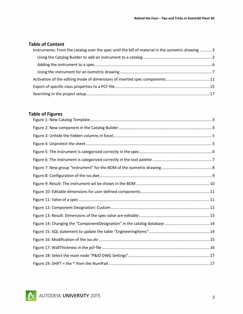
Create a new valve
Figure 2: New component in the Catalog Builder
Select a parametric graphic of your choice and fill the specific fields. Leave for “Piping Component” the value “Valve”. We will change it later
Save
Click “Export to Excel”
Open the Excel-file
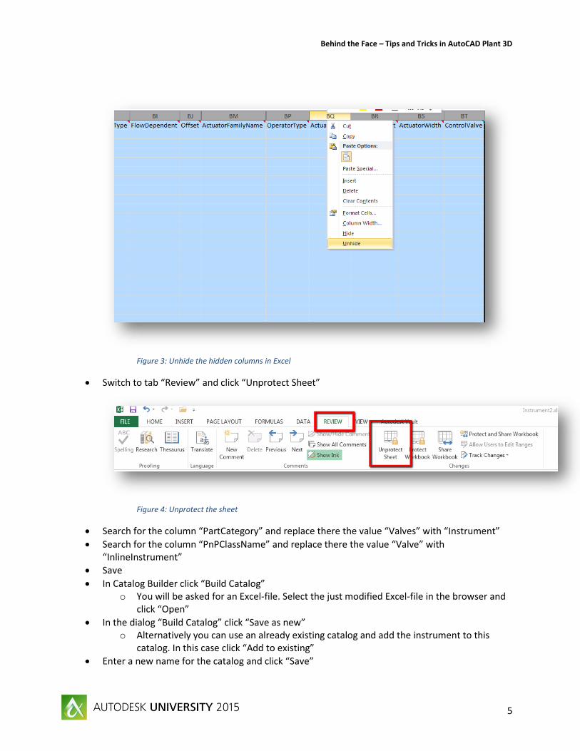
Select all columns and choose from context menu “Unhide” o Note: Select also the last empty column because between this column and the last filled
column are still some columns hidden
Behind the Face – Tips and Tricks in AutoCAD Plant 3D
5
Figure 3: Unhide the hidden columns in Excel
Switch to tab “Review” and click “Unprotect Sheet”
Figure 4: Unprotect the sheet
Search for the column “PartCategory” and replace there the value “Valves” with “Instrument”
Search for the column “PnPClassName” and replace there the value “Valve” with “InlineInstrument”
Save
In Catalog Builder click “Build Catalog” o You will be asked for an Excel-file. Select the just modified Excel-file in the browser and
click “Open”
In the dialog “Build Catalog” click “Save as new” o Alternatively you can use an already existing catalog and add the instrument to this
catalog. In this case click “Add to existing”
Enter a new name for the catalog and click “Save”
Behind the Face – Tips and Tricks in AutoCAD Plant 3D
6
The catalog with the instrument will be created and can now be opened in the Catalog Editor. Now we add this instrument to a spec.
Adding the instrument to a spec
Open a spec of your choice of the current Plant 3D project
Open the just created catalog
For the following isometric exercise type for the ISO symbol type the value “INSTRUMENT” and for the SKEY the value “IIBG”. For “BG” you can also use a different string combination
Click “Save in Catalog”
Switch to the tab “Spec Editor”
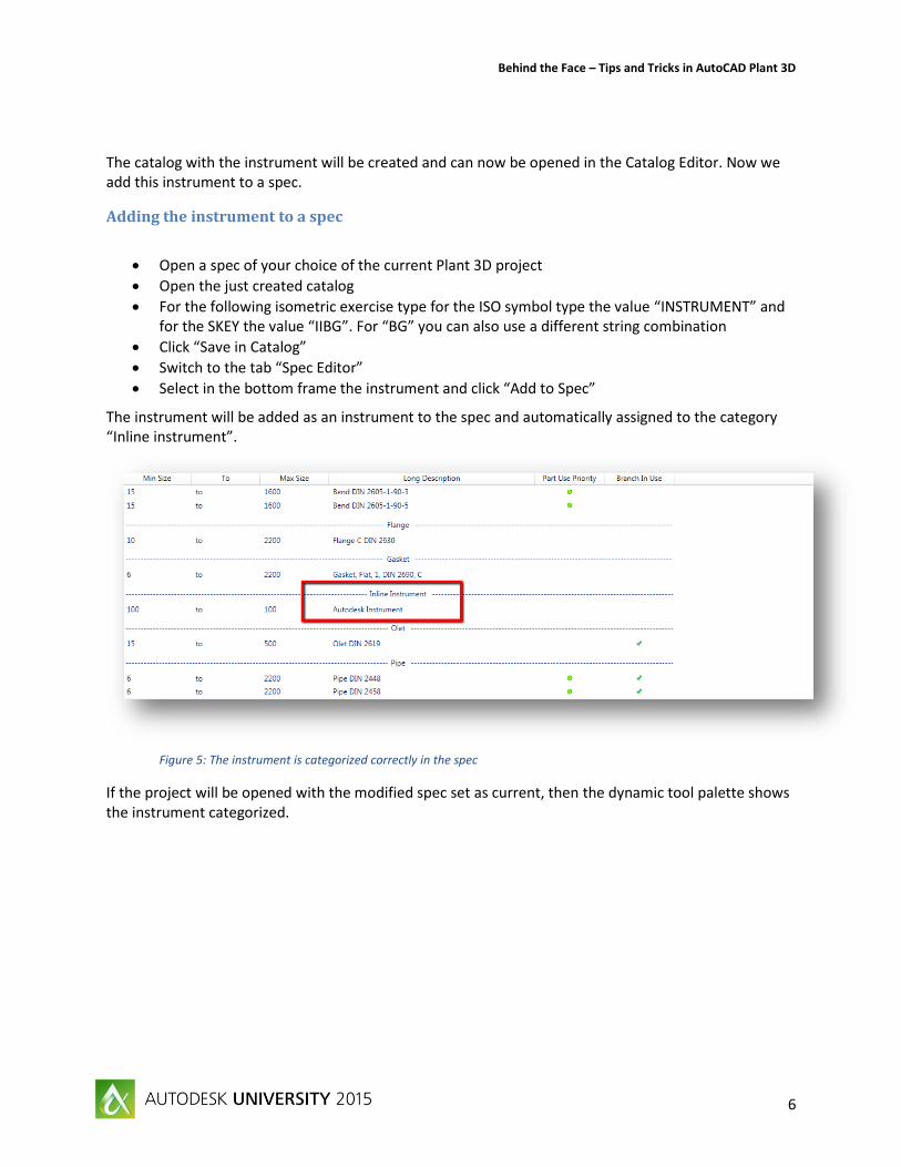
Select in the bottom frame the instrument and click “Add to Spec”
The instrument will be added as an instrument to the spec and automatically assigned to the category “Inline instrument”.
Figure 5: The instrument is categorized correctly in the spec
If the project will be opened with the modified spec set as current, then the dynamic tool palette shows the instrument categorized.
Behind the Face – Tips and Tricks in AutoCAD Plant 3D
7
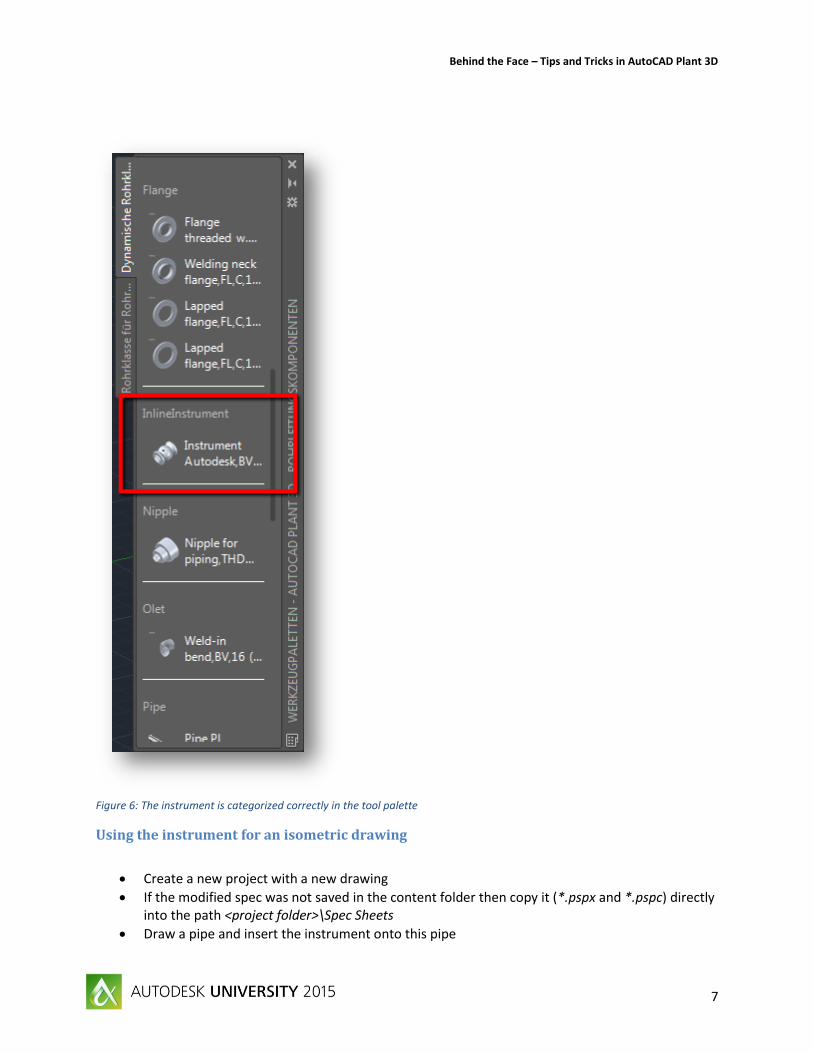
Figure 6: The instrument is categorized correctly in the tool palette
Using the instrument for an isometric drawing
Create a new project with a new drawing
If the modified spec was not saved in the content folder then copy it (*.pspx and *.pspc) directly into the path <project folder>\Spec Sheets
Draw a pipe and insert the instrument onto this pipe
Behind the Face – Tips and Tricks in AutoCAD Plant 3D
8
Save
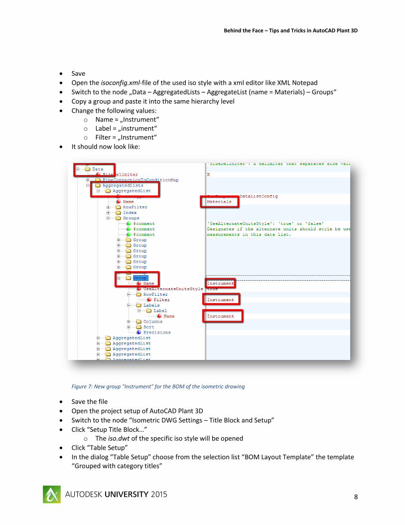
Open the isoconfig.xml-file of the used iso style with a xml editor like XML Notepad
Switch to the node „Data – AggregatedLists – AggregateList (name = Materials) – Groups“
Copy a group and paste it into the same hierarchy level
Change the following values: o Name = „Instrument“ o Label = „instrument“ o Filter = „Instrument“
It should now look like:
Figure 7: New group "Instrument" for the BOM of the isometric drawing
Save the file
Open the project setup of AutoCAD Plant 3D
Switch to the node “Isometric DWG Settings – Title Block and Setup”
Click “Setup Title Block…” o The iso.dwt of the specific iso style will be opened
Click “Table Setup”
In the dialog “Table Setup” choose from the selection list “BOM Layout Template” the template “Grouped with category titles”
Behind the Face – Tips and Tricks in AutoCAD Plant 3D
9
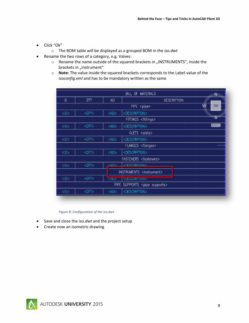
Click “Ok” o The BOM table will be displayed as a grouped BOM in the iso.dwt
Rename the two rows of a category, e.g. Valves: o Rename the name outside of the squared brackets in „INSTRUMENTS“, inside the
brackets in „instrument“ o Note: The value inside the squared brackets corresponds to the Label-value of the
isoconfig.xml and has to be mandatory written as the same
Figure 8: Configuration of the iso.dwt
Save and close the iso.dwt and the project setup
Create now an isometric drawing
Behind the Face – Tips and Tricks in AutoCAD Plant 3D
10
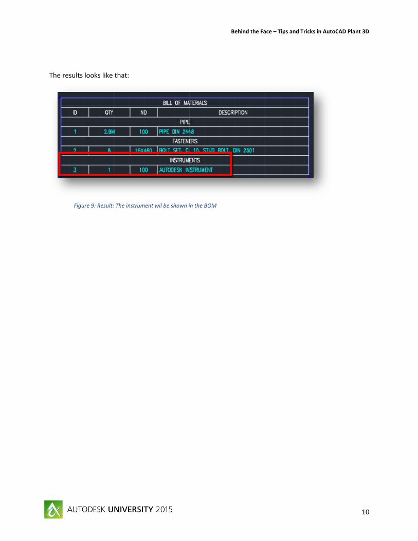
The results looks like that:
Figure 9: Result: The instrument wil be shown in the BOM
Behind the Face – Tips and Tricks in AutoCAD Plant 3D
11
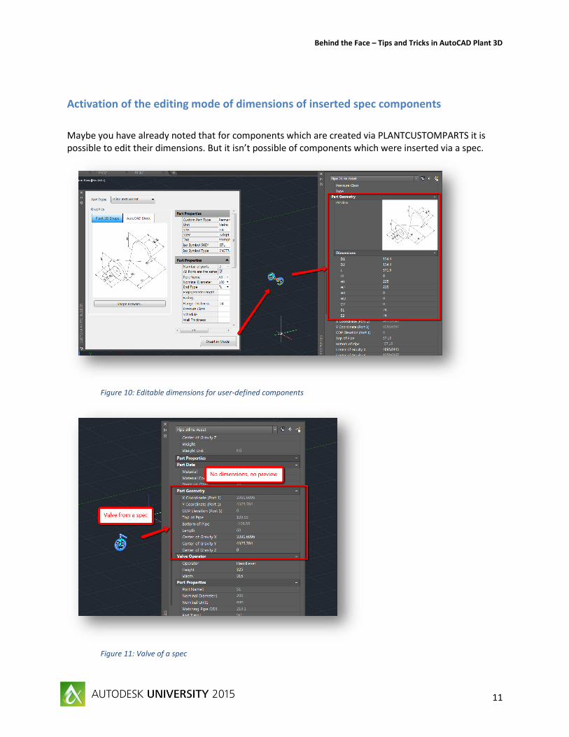
Activation of the editing mode of dimensions of inserted spec components
Maybe you have already noted that for components which are created via PLANTCUSTOMPARTS it is possible to edit their dimensions. But it isn’t possible of components which were inserted via a spec.
Figure 10: Editable dimensions for user-defined components
Figure 11: Valve of a spec
Behind the Face – Tips and Tricks in AutoCAD Plant 3D
12
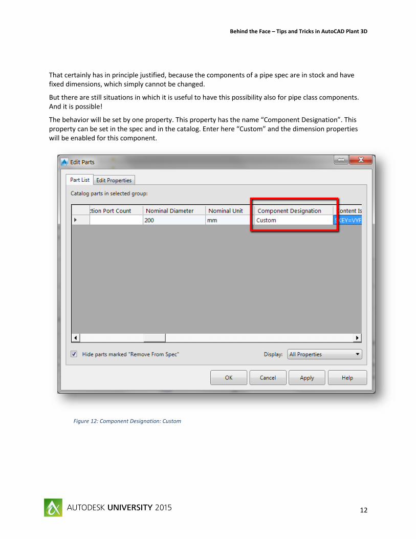
That certainly has in principle justified, because the components of a pipe spec are in stock and have fixed dimensions, which simply cannot be changed.
But there are still situations in which it is useful to have this possibility also for pipe class components. And it is possible!
The behavior will be set by one property. This property has the name “Component Designation”. This property can be set in the spec and in the catalog. Enter here “Custom” and the dimension properties will be enabled for this component.
Figure 12: Component Designation: Custom
Behind the Face – Tips and Tricks in AutoCAD Plant 3D
13
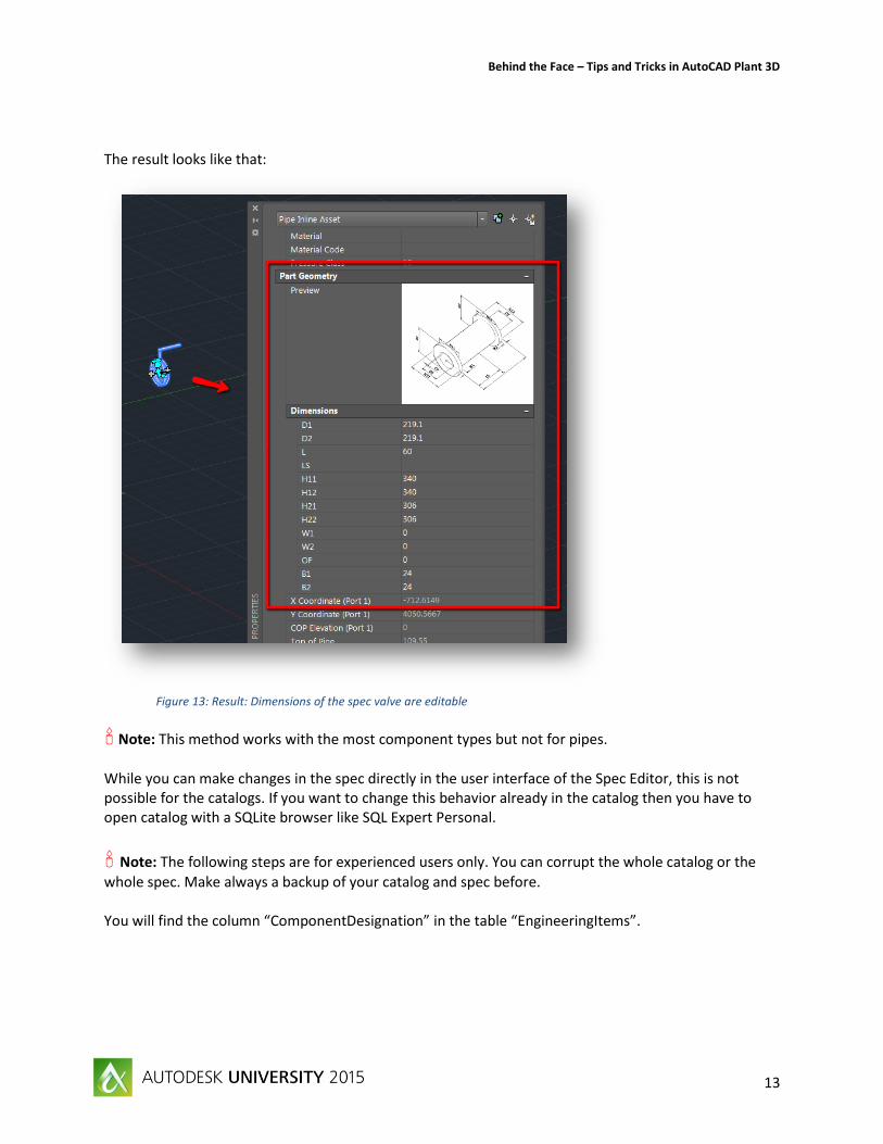
The result looks like that:
Figure 13: Result: Dimensions of the spec valve are editable
Note: This method works with the most component types but not for pipes.
While you can make changes in the spec directly in the user interface of the Spec Editor, this is not possible for the catalogs. If you want to change this behavior already in the catalog then you have to open catalog with a SQLite browser like SQL Expert Personal.
Note: The following steps are for experienced users only. You can corrupt the whole catalog or the
whole spec. Make always a backup of your catalog and spec before. You will find the column “ComponentDesignation” in the table “EngineeringItems”.
Behind the Face – Tips and Tricks in AutoCAD Plant 3D
14
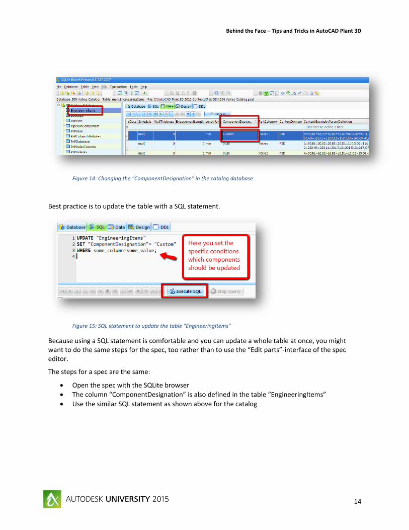
Figure 14: Changing the "ComponentDesignation" in the catalog database
Best practice is to update the table with a SQL statement.
Figure 15: SQL statement to update the table "EngineeringItems"
Because using a SQL statement is comfortable and you can update a whole table at once, you might want to do the same steps for the spec, too rather than to use the “Edit parts”-interface of the spec editor.
The steps for a spec are the same:
Open the spec with the SQLite browser
The column “ComponentDesignation” is also defined in the table “EngineeringItems”
Use the similar SQL statement as shown above for the catalog
Behind the Face – Tips and Tricks in AutoCAD Plant 3D
15
Export of specific class properties to a PCF-file
You need pcf-files for the data exchange with different applications. For example some applications are using pcf-files for analysis of pipeline systems, e.g. Rohr2. By default specific class properties will be already saved as information to a pcf-file when creating an isometric drawing, like material and pressure class. You can also save different properties to the pcf-file. How to do this is described here using the example of the wall thickness.
Therefore we have to modify the iso.atr-file of the used iso style. This file is saved in <project folder>\Isometric\<Iso Style>. It is a simple text file and can be opened with Notepad.
You note here two sections: ATTRIBUTES and BOM-ATTRIBUTES. The section ATTRIBUTES is for more general properties. These are precisely properties of the project, of the drawing, LTD-properties and pipeline group properties. All other properties, this means all class properties with the exception of the pipeline group, will be set in the section BOM-ATTRIBUTES.
The WallThickness is a property of the class „Piping and Equipment“. This class will be named in the iso.atr as “EngineeringItems”. The most classes are named in iso.atr like they are name in the project setup, e.g. WallThickness for WallThickness. There are two exceptions: “General” for project properties and “EngineeringItems” for “Piping and Equipment”.
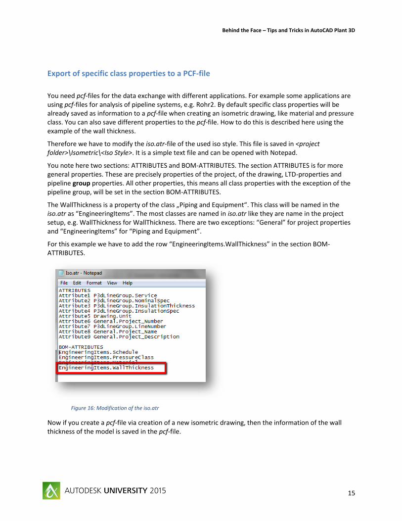
For this example we have to add the row “EngineeringItems.WallThickness” in the section BOM-ATTRIBUTES.
Figure 16: Modification of the iso.atr
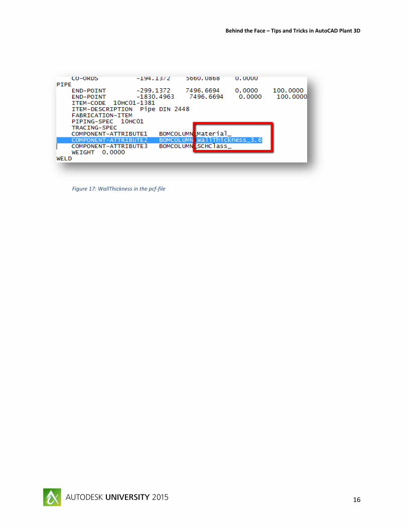
Now if you create a pcf-file via creation of a new isometric drawing, then the information of the wall thickness of the model is saved in the pcf-file.
Behind the Face – Tips and Tricks in AutoCAD Plant 3D
16
Figure 17: WallThickness in the pcf-file
Behind the Face – Tips and Tricks in AutoCAD Plant 3D
17
Searching in the project setup
If you’ve got a strong customized project with many, many class definitions, it can be very challenging to find the right class in the project setup. There is a simple trick to find the classes which are starting by some specific letters.
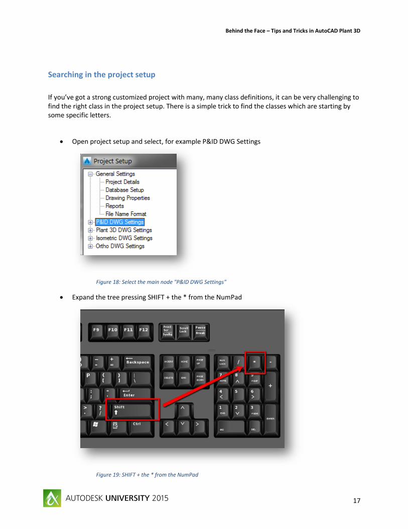
Open project setup and select, for example P&ID DWG Settings
Figure 18: Select the main node "P&ID DWG Settings"
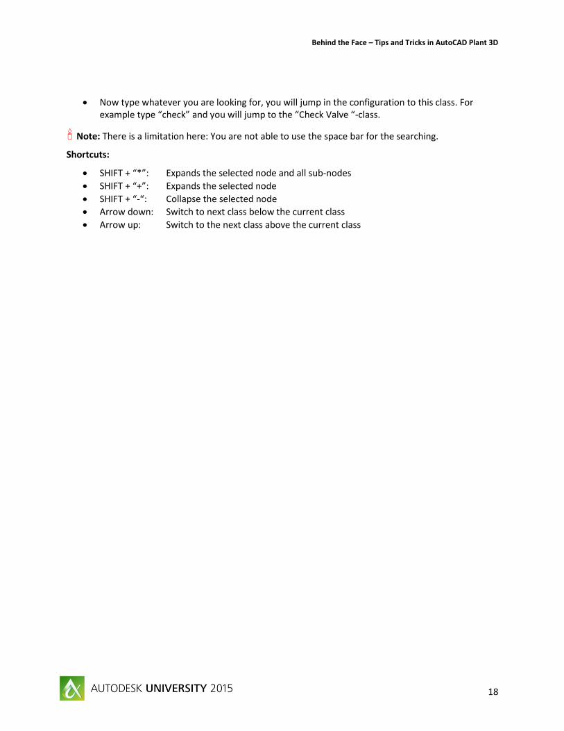
Expand the tree pressing SHIFT + the * from the NumPad
Figure 19: SHIFT + the * from the NumPad
Behind the Face – Tips and Tricks in AutoCAD Plant 3D
18
Now type whatever you are looking for, you will jump in the configuration to this class. For example type “check” and you will jump to the “Check Valve “-class.
Note: There is a limitation here: You are not able to use the space bar for the searching.
Shortcuts:
SHIFT + “*”: Expands the selected node and all sub-nodes
SHIFT + “+”: Expands the selected node
SHIFT + “-“: Collapse the selected node
Arrow down: Switch to next class below the current class
Arrow up: Switch to the next class above the current class