oil and gas pipeline services overview - · pdf fileintegrating expertise in materials...
TRANSCRIPT

■ Pipeline Integrity Engineering
■ Corrosion Engineering Services
■ Advanced Inspection
■ Training
Pipeline Services

P I P E L I N ES E R V I C E S
CORPORATE SNAPSHOT
■ Employee-owned company founded in 1983 in San Jose, CA
■ Branch offices through-out the United States and Canada, as well as over-seas affiliates
■ 250+ employees providing consistent innovation and service
Structural Integrity Associates, Inc., is a leading engineering and consulting firm dedicated to the analysis, control, and prevention of structural failures. Founded in 1983 in San Jose, CA, we have since opened branch offices throughout the United States and Canada, and established overseas affiliates.
We pride ourselves on innovation marked by a creative multi-disciplined approach to component evaluation and repairs. Our services are supported through the development of increasingly sophisticated tools reflecting a unique blend of technical expertise with the latest computer and expert system technologies.
Over the years, Structural Integrity has established itself as an innovative and responsive resource for answering virtually any challenge in the analysis, control, and prevention of failures in critical equipment. Our experience ranges from R&D to engineering, metallurgy, and fabrication, and from petrochemical applications to nuclear and fossil-fueled power plant support. With several offices and experts throughout the U.S., we can quickly and effectively help your engineering needs.
Ensuring the continued safe, reliable operation of key infrastructure involves an understanding of the potential degradation mechanisms, knowledge of the optimal inspection methods to quantify the condition of the asset, and the engineering expertise to analyze the information to make an informed decision as to the remaining operability of a component or system. This is what we refer to as Integrated Assessments.
Operators increasingly require greater assessment and engineering expertise to determine if their pipeline/piping assets are fit for service. By integrating expertise in materials degradation, structural mechanics, and regulatory requirements with advanced inspection technologies, Structural Integrity is uniquely positioned to assist operators with difficult to assess projects.
ABOUT STRUCTURAL INTEGRITY
ABOUT STRUCTURAL INTEGRITY’S INTEGRATED ASSESSMENT SERVICES
Structural Integrity Associates, Inc. will be recognized as the most trusted independent provider of innovative, best in value, fully integrated engineered solutions
to the Energy industry.
SI MISSION STATEMENT
2

P I P E L I N ES E R V I C E S
OUR SERVICES INCLUDE
o Guided Wave Testing (GWT)o Electro-Magnetic Acoustic Transducers (EMAT)o External Corrosion Direct Assessment (ECDA)o Internal Corrosion Direct Assessment (ICDA) o Distribution Integrity Management Program (DIMP)o Penstock Evaluationo Failure and Root Cause Analysiso Strength and Hardness Testingo Geographic Information Systems (GIS)o Managing Buried Assetso Managing Aging Piping Program (MAPProTM)o Cathodic Protectiono Area Potential - Earth Current (APEC) Survey o External Corrosion Rate Estimator for Buried Steel (SoilPro)o Technical Training and Workshops
ABOUT SI PIPELINE SERVICES
.................................................04.........................05
...........................06............................07
...................08..............................................................10
............................................11...............................................12
....................................13.......................................................14
..........................15..............................................................16
..........................17.........18
..........................................19
3877 -474 -7693
CORPORATE MILESTONES
■ 1983 – Company Founded in San Jose, CA
■ 1985 – Opened Infometrics; NDE Products Business
■ 1989 – Established Fossil Plant Services in Uniontown, OH
■ 1991 – Acquired IST, Inc. and Focused Array UT Inspection Technology in Ft. Lauderdale, FL
■ 1995 – Opened Charlotte, NC Office
■ 2000 – Opened Denver, CO Office
■ 2002 – Established Materials Science Center in Austin, TX Office
■ 2002 – Opened Stonington, CT Office
■ 2004 – Acquired GWT Technology; Established Pipeline Services Group
■ 2005 – Opened Structural Integrity Canada in Toronto, Ontario
■ 2008 – Opened Chattanooga, TN Office
■ 2011 – Acquired the Inspection Services Group from FBS, Inc.
■ 2012 – Preferred vendor with Utilities Service Alliance (USA)
■ 2012 – Acquired TubeTrack (Power Plant Data Management Software)
■ 2013 – Achieved two million hours worked without a lost time injury
■ 2013 – Structural Integrity’s 30 Year Anniversary
■ 2013 – Established affiliate in Europe

Guided Wave inspection is a low frequency ultrasonic guided wave technique developed for the rapid survey of pipes to detect both internal and external wall loss in difficult to reach pipelines.
WHY USE GWT?Because GWT does not require complete access to the entire pipeline, more cost-effective inspection and mitigation is possible by eliminating the need for a complete excavation or insulation removal.
HOW DOES GWT WORK?GWT uses multiple transducer arrays to direct sound energy in a circumferential mode, which creates a torsional guided wave within the pipe walls. These torsional waves propagate down the pipe and reflect off features such as welds, supports, or areas of wall loss. These reflections are then collected and analyzed to identify locations and nature of the indications.
0.0
0.5
1.0
1.5
2.0
-20.0 10.0 0.0DISTANCE
Am
p (m
V)
Welds
External Corrosion
TYPICAL GWT APPLICATIONS ■ Detecting Corrosion Under Insulation (CUI)
■ Assessing Buried Pipelines ■ Locating Girth Welds ■ Detecting Metal Loss in Plant Piping
■ High Energy Piping for Flow Assisted Corrosion
■ Extending the Range of ICDA Excavations
■ Assessing Cased Sections of Pipeline
Propagation along the pipeline
Transmitter/Receiver
wavewave Flange or Pipe end
PipeRegion inspected
GUIDED WAVE TESTING (GWT)
P I P E L I N ES E R V I C E S
4

Detecting localized corrosion in metal structures with a large surface area can be challenging. Electro-Magnetic Acoustic Transducers (EMAT) are capable of inspecting piping, tanks, and other components at a high speed, screening for corrosion defects, gouges, and cracks. Once an anomaly is detected, the extent of degradation is confirmed using traditional ultrasonic thickness equipment.
WHY USE EMAT?EMAT provides greater flexibility overcoming limitations in conventional Long-Range Guided Wave techniques by not requiring complete circumferential access or circular dimensions of the item inspected. In many cases, EMAT can be used without coating removal. Semi-automatic crawlers also allow the inspection of areas inaccessible without scaffolding. EMAT provides a 100% volumetric inspection that is fast and repeatable. EMAT can be used on the exterior or interior of piping systems.
HOW DOES EMAT WORK?Although the acoustics are similar in principle to conventional Guided Wave inspection, EMAT uses electromagnetic induction to generate ultrasonic waves in a component. The change in signal between the transmission and receiving sensors indicates metal loss. EMAT does not require couplant, and can be used at higher temperatures and at higher inspection speeds than conventional ultrasonic methods.
TYPICAL EMAT APPLICATIONSEMAT is extremely flexible and capable of inspecting a wide range of applications including large surface areas, components with coatings, difficult to access areas, and high temperature components. Typical applications include:
■ Penstocks and other large diameter piping ■ Tanks and storage systems ■ Hard-to-reach and irregular pipeline elbows/dimensions ■ Power Plant circulating water systems ■ Large Diameter (greater than 36-inch) pipe
EMAT INSPECTION
P I P E L I N ES E R V I C E S
5877 -474 -7693

External Corrosion Direct Assessment (ECDA) is an alternate inspection methodology approved by DOT 49 CFR Part 192 and Part 195 to assess external corrosion.
ECDA is a four step process that leverages sound engineering principles, above ground indirect inspection technologies, data integration and engineering analysis to determine the integrity of a pipeline system. ECDA locates where damage is likely to initiate in addition to detecting areas with ongoing corrosion. This process optimizes excavation site selection, improving the likelihood that significant damage is evaluated, thereby reducing the risk of failure.
EXTERNAL CORROSIONDIRECT ASSESSMENT (ECDA)
APPLICATIONS OF ECDA ■ Transmission piping ■ Distribution piping ■ Fuel piping to power plants and industry users
PROJECT IMPLEMENTATION AND PROCEDURE DEVELOPMENT• Turnkey project management – all engineering, data management, inspection
& reporting• Development and Enhancement of written ECDA procedures in accordance
with 49 CFR 192.925 and NACE SP0502
STEP 1: PRE-ASSESSMENT• Engineering analysis of pipeline systems • TurboECDATM software assists with data management and ECDA process
documentation STEP 2: INDIRECT INSPECTIONS
• Knowledge and expertise in the selection, field testing and data integration of Close interval Pipe-to-Soil Potential Surveys (CIS), Direct Current Voltage Gradient (DCVG), AC Current Attenuation Survey, soil resistivity, Alternating Current Voltage Gradient (ACVG), and C-Scan
STEP 3: DIRECT INSPECTIONS• Data Interpretation, including Structural Integrity’s SoilProTM soil corrosion
model, to optimize excavation site selection • Bellhole inspections, NDT, Remote Visual, Hardness and Alloy Identification• Guided Wave Testing (GWT) • Detailed thickness mapping using semi-automated UT (B-Scan)• Specialized techniques such as Time-of-Flight Diffraction, Annular and Linear
Phased Array UT, Eddy Current, Boresonics, and Micro-TOFD for character-izing cracks
STEP 4: POST ASSESSMENT• Engineering analysis quantify remaining strength re-assessment intervals,
development of repair plans and monitoring programs to restore the integrity of pipeline system
• Prevention and mitigation measures to minimize further degradation
P I P E L I N ES E R V I C E S
6

IDENTIFYING INTERNAL CORROSION IN NORMALLY DRY GAS PIPELINES
Pipeline Integrity Management regulations require that operators of natural gas pipelines verify the absence of internal corrosion damage. This regulation impacts all operators under 49CFR 192 – gas transmission, local distribution and owners of service pipelines to plants or utilities.
Many of the older and/or small diameter pipelines can not be inspected using inline inspection tools (i.e., smart pigs). Concerns over interruption of service and difficulties in dehydrating pipelines after inspection minimize the use of hydrostatic testing. This leaves pipeline operators with only one remaining option – Internal Corrosion Direct Assessment (ICDA) to demonstrate the absence of metal loss and/or the absence of the internal corrosion threat.
ICDA is a 4-step process that involves data gathering and alignment, knowledge of the pipeline elevation profile, corrosion engineering to select optimal sites for excavation and NDE inspections, and a significant amount of documentation. Structural Integrity has developed a process to systematically and predictably assess pipelines for the threat of Internal Corrosion.
1 PRE-ASSESSMENT• Integration of pipeline data combined with Subject Matter Expert interviews • Steady state flow modeling to determine changing flow conditions along a
pipeline system
2 REGION IDENTIFICATION• Create pipeline elevation & inclination profiles using pipeline centerline and
digital elevation data (no surveys) • Calculate critical inclination angles with the potential to retain liquid based
on steady state flow modeling info• Field verify pipeline inclination profiles to improve accuracy
3 DETAILED EXAMINATION• Screen suspect inclination sites with GWT to locate the worst internal metal
loss. • Quantitatively measure wall thickness and map the wall profile using semi-
automated UT thickness (B-Scan)
4 POST-ASSESSMENT • Engineering analysis to determine remaining strength and re-assessment
intervals. • Documentation of ICDA effectiveness, monitoring and mitigation measures.
The streamlined ICDA process can be used on a single line or a network of pipe. The Structural Integrity approach can be used to document the absence of an internal corrosion threat, or as a complete ICDA integrity assessment. We can complete most projects in a few weeks. Complete, turnkey ICDA services generally require less than 3 months.
INTERNAL CORROSIONDIRECT ASSESSMENT (ICDA)
P I P E L I N ES E R V I C E S
7877 -474 -7693
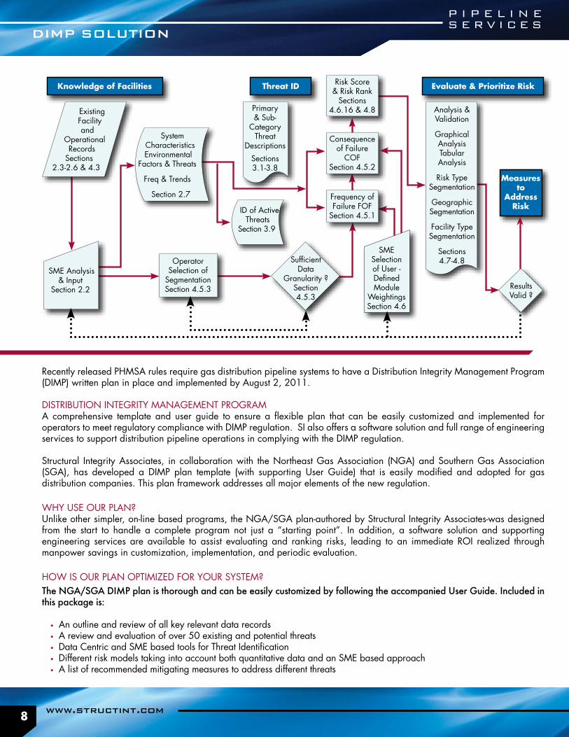
Recently released PHMSA rules require gas distribution pipeline systems to have a Distribution Integrity Management Program (DIMP) written plan in place and implemented by August 2, 2011.
DISTRIBUTION INTEGRITY MANAGEMENT PROGRAMA comprehensive template and user guide to ensure a flexible plan that can be easily customized and implemented for operators to meet regulatory compliance with DIMP regulation. SI also offers a software solution and full range of engineering services to support distribution pipeline operations in complying with the DIMP regulation.
Structural Integrity Associates, in collaboration with the Northeast Gas Association (NGA) and Southern Gas Association (SGA), has developed a DIMP plan template (with supporting User Guide) that is easily modified and adopted for gas distribution companies. This plan framework addresses all major elements of the new regulation.
WHY USE OUR PLAN?Unlike other simpler, on-line based programs, the NGA/SGA plan-authored by Structural Integrity Associates-was designed from the start to handle a complete program not just a “starting point”. In addition, a software solution and supporting engineering services are available to assist evaluating and ranking risks, leading to an immediate ROI realized through manpower savings in customization, implementation, and periodic evaluation.
HOW IS OUR PLAN OPTIMIZED FOR YOUR SYSTEM?The NGA/SGA DIMP plan is thorough and can be easily customized by following the accompanied User Guide. Included in this package is:
• An outline and review of all key relevant data records • A review and evaluation of over 50 existing and potential threats• Data Centric and SME based tools for Threat Identification• Different risk models taking into account both quantitative data and an SME based approach• A list of recommended mitigating measures to address different threats
Knowledge of Facilities Evaluate & Prioritize RiskThreat ID
Measures to
Address Risk
ExistingFacilityand
OperationalRecords
Sections2.3-2.6 & 4.3
SME Analysis & Input
Section 2.2
System Characteristics Environmental
Factors & Threats
Freq & Trends
Section 2.7
ID of Active Threats
Section 3.9
Primary & Sub-
Category Threat
Descriptions
Sections3.1-3.8
Operator Selection of
Segmentation Section 4.5.3
Consequence of Failure
COFSection 4.5.2
SufficientData
Granularity ?Section4.5.3
Risk Score & Risk Rank
Sections 4.6.16 & 4.8
SME Selection of User - Defined Module
Weightings Section 4.6
Frequency of Failure FOF
Section 4.5.1
Analysis & Validation
Graphical AnalysisTabular Analysis
Risk TypeSegmentation
Geographic Segmentation
Facility TypeSegmentation
Sections4.7-4.8
ResultsValid ?
DIMP SOLUTION
P I P E L I N ES E R V I C E S
8

ArchiveResults
Incidents
One-callRecords
DIRTReports
Leak Records
GIS
What-if?Scenarios
Run & Maintain Risk Algorithms
User-selectable Output
PLAN FRAMEWORK AND USER GUIDEThe Plan framework and user guide meet all elements of PHMSA’s DIMP Final Rule, and can be readily customized to meet each pipeline operator’s needs.
47 member companies of SGA and NGA have already purchased the written Program. These 47 companies collectively serve more than 40% of the distribution customers in the U.S.
DIMP PLAN CUSTOMIZATIONStructural Integrity recognizes that each operator’s system is unique with its own distinct threats and challenges. We can help operators adapt and implement a plan that will meet their specific needs.
We’ll will also be available to review or audit both the process and implementation status of the client’s own DIMP plans.
DIMP SOFTWARE TOOLSSI has teamed with New Century Software to offer an industry-leading software solution and supporting services to assist gas distribution operators in complying with pending regulation for Distribution Integrity Management. This DIMP solution will provide a flexible framework that is capable of being adapted to each operator’s unique requirements of their system.
DIMP SOLUTION
Prepared By:
P I P E L I N ES E R V I C E S
9877 -474 -7693

Structural Integrity has assessed over 45,000 feet of steel penstocks for various clients. We have experience in evaluation of degradation mechanisms, development of acceptance criteria, determination of assessment methodologies, inspection equipment & techniques, and flaw evaluation. We know where and how to look for degradation, as well as how to determine degradation rates.
Penstock failures can be catastrophic. Proper identification of all the degradation mechanisms is critical. Overlooking or under estimating a degradation mechanism can lead to unexpected failures. Understanding the degradation mechanism aids in better identifying key assessment regions and assessment methodologies.
INSPECTION TECHNOLOGIESA variety of inspection technologies are available for the assessment of penstocks. Most inspections can be performed while in-service and without coating removal.
• B-Scan UT– metal loss• Guided Wave Testing (GWT) – metal loss• Electromagnetic Accoustic Transducer (EMAT) – metal loss• Voltage Gradient and Cell-to-Cell Surveys – coating damage and corrosion• SoilPro – soil corrosivity
ENGINEERING• Development of Steel Penstock Inspection Guides • Field data collection • Inspection for, and analysis of, localized internal corrosion adjacent to both
circumferential and longitudinal riveted lap joints • Evaluation of external and internal corrosion on fitness for purpose• Wall loss/operating pressure plots • Wall loss/failure pressure curves • Fracture Mechanics analysis • Reinspection intervals and repair plans • GIS based data presentations• Provides summary presentation of results to show conditions on a system
wide basis.
EXPERIENCE & CAPABILITIES ■ Developed inspection tools that can rapidly screen for wall loss
■ Structural Integrity maintains a database of vintage penstock material properties
■ Key knowledge of critical areas for a more effective assessment
■ Understanding that degradation rates can be several times greater than nominal rates at localized regions
■ Experience in locating and inspecting these areas of degradation
■ Structural Integrity has a great deal of experience with the development of comprehensive Integrity Management Plans.
PENSTOCK EVALUATION
P I P E L I N ES E R V I C E S
10

Determining the cause of failures and degradation so that adjustments can be made to programs and procedures reduces the likelihood that similar accidents or incidents will occur in the future.
BENEFITSFailure analysis determines the mechanism by which a failure occurs while a root cause analysis explores the factors contributing to the conditions that allowed the mechanism of failure to exist. Understanding both allows for a proper corrective action plan.
For example, a failure analysis might determine that a repaired girth weld failed by brittle fracture when subjected to axial strains. However, the root cause analysis explores what conditions existed that allowed a weld with insufficient strain capacity to exist. Was the possibility of high axial strains recognized in the design stage? If not, why not? Was the welding procedure appropriate for this application? Was the weld inspection conducted properly? Did periodic pipeline patrol fail to recognize the ground deformation? Only after the root cause is established can appropriate changes to policies, procedures, training, and organizations be made to prevent or minimize recurrence of the failure.
EXPERTISEThe technical staff of Structural Integrity’s Pipeline Services (PLS) group includes metallurgical engineers with 30 years experience in failure analysis and root cause analysis for pipeline, oil & gas production, and geothermal industries.
FAILURE AND ROOT CAUSE ANALYSIS
LABORATORY CAPABILITIES Our corrosion experts are supported by our own Structural Integrity Materials Science Center in Austin, TX which is fully equipped to perform metallurgical analysis.
■ Optical Metallography and Fractography
■ Quantitative Microstructural analysis
■ Mechanical property analysis (tensile, toughness, hardness and composition analysis)
■ Scale and Deposit analysis ■ Scanning Electron Microscopy (SEM)
■ Specialized corrosion testing
P I P E L I N ES E R V I C E S
11877 -474 -7693

FIELD PORTABLE HARDNESS TESTINGFederal pipeline regulations applicable to natural gas and hazardous liquid pipeline currently require the use of destructive testing using standard size tensile samples to determine the strength of pipe for which the yield strength is unknown. However, other methods of determining yield strength may be proposed to PHMSA for acceptance using the waiver process, and there may be applications for hardness testing other than the determination of strength.
Field portable hardness testers can nondestructively provide operators with hardness data, but the accuracy of such data is reliant upon selecting the most appropriate test method for a specific application and following a detailed procedure for surface preparation, testing, and data assessment. Structural Integrity’s Pipeline Services can train operators in the correct application of field hardness testing, including the use of hardness test data to estimate yield strength, or we can perform field hardness testing at your location.
STRENGTH AND HARDNESS TESTING
P I P E L I N ES E R V I C E S
12

Geographic Information Systems, (GIS) can deliver integration options not possible with traditional relational databases, ultimately supporting enhanced engineering analyses. GIS enables engineers to make more-informed decisions in an effective and intuitive manner by providing tools for the visualization, analysis, and synthesis of information.
One of the best ways to access and manage pipeline features is through a GIS. Project features can be displayed in a 2D or 3D environment. Features are directly integrated into a GIS model by digitizing drawings or field GPS data collection. Symbology allows multi-variable characterization. Spatial analysis tools provide a new approach to the integration and evaluation information. The ability to locate adverse combinations of data based on recurring patterns allows an engineer to evaluate the impact of a degrading element using multiple indicators and simultaneously querying features for specific or coincident attributes.
Structural Integrity populates project data into a single file and provides an easy to use graphical database interface to view results.
GIS PROJECT FILES CAN CONTAIN• Aerial or satellite Imagery and road features• Convert as-built drawings to background images• Digitized drawing information - to scale proper orientation • All asset information: design, operation, maintenance, inspection, historical, etc. • Inspection data: CP, ILI, UT, G-Scan, etc. • ICDA elevation profiles & inclination analysis • Risk analysis results • Site photos• Client or public GIS data (i.e., soil, HCA, buildings)
DELIVERY SOLUTION OPTIONS• 2D or 3D• Maps and Alignment Sheets • Training• Spill & interference modeling
GEOGRAPHIC INFORMATION SYSTEMS(GIS)
SUCCESSFULLY USED ON: ■ Transmission pipelines ■ Penstocks & Pressure Conduits ■ Boiler Tubes ■ Nuclear Power Plant buried piping
■ Excavation planning (dig sheets)
P I P E L I N ES E R V I C E S
13877 -474 -7693

Structural Integrity Associates has extensive experience with the assessment of buried piping systems in nuclear power plants, as well as other regulated industries, allowing us to bring multiple industry best practices to your plant or operation.
For example, SI has been supporting nuclear power plants with buried piping issues since 2002. Working in close partnership with the Electric Power Research Institute (EPRI), which conducts research to ensure nuclear power remains a safe and economically feasible generation option, and as part of an EPRI Balance of Plant Corrosion project. We have also been developing the new nuclear industry database and interface software for managing all nuclear buried piping data including:
• design• maintenance• inspection information
A meaningful risk ranking approach must be capable of differentiating the unique levels of risk of individual buried piping sections around a plant or other type of operation. Risk ranking identifies the magnitude, timing, locations, and tools required to characterize the condition of the buried piping.
Structural Integrity’s experience with life cycle management, risk assessment, inspection, remediation, and mitigation provides the basis for an in-depth understanding of the challenges that plants face in managing a large amounts of buried piping in a plant environment. Structural Integrity staff are leaders in the pipeline industry dealing with the data integration and unique inspection methodologies required to assess buried components. We have applied this understanding in the development of the Managing Aging Piping (MAP) program for buried assets, which provides a road map necessary to plan, document, inspect, and maintain buried systems using a consistent, analytical decision making process.
MANAGING BURIED ASSETS
2010 MAPPro™ All rights reserved
™
Manage Data Risk Management Con�guration
Buried Pipe Data ManagerVersion: 1.0.0.22 Build: 22 Date: 1/13/2010
Developed in conjunction with:
P I P E L I N ES E R V I C E S
14

MAPProTM is a comprehensive corrosion engineering based program and database tool for use in extending the useful operating life of underground piping and tanks in Nuclear Power Plants.
The program, developed by Structural Integrity integrates proven plant procedures (design, risk, inspection, fitness for purpose, apparent cause analysis, monitoring, etc.) into a repeatable process to reduce the likelihood of a failure that could impact plant reliability or the environment.
Our corrosion experts have developed specialized risk algorithms that consider the industry’s unique degradation mechanisms, combined with the latest corrosion prediction calculation models, to yield optimal prioritization strategies.
We participates in hundreds of miles of buried piping inspections each year which makes us a proven partner when selecting and implementing an inspection solution.
Our program is supported by a state of the art database and data visualization tool – MAPProView. These analysis tools integrate design, inspection and operating history together to reveal patterns not previously observed.
KEY PROGRAM PHASES:• Baseline Phase
o System Conditions and Data Integration o Risk Assessment
• Inspection Phase o Indirect Inspections o Direct Inspections
• Remediation Phase• Mitigation Phase
This is a continuous process with routine System Health metrics. This process can be integrated into your existing philosophy to enhance process rigor or to supplement techniques and decision criteria new to the site.
MANAGING AGING PIPING PROGRAM(MAPPROTM)
MAP SERVICES: ■ Cathodic Protection, Soil, G-Scan
■ Flaw Handbook calculations ■ Defect Disposition & Remediation Design
■ CP System Design and installation
P I P E L I N ES E R V I C E S
15877 -474 -7693

Cathodic Protection (CP) can be an effective tool in the protection of any buried metal structure from corrosion as long as the unique conditions of the piping configuration are thoroughly understood. Proper system design, maintenance and effectiveness testing are required in order to achieve optimal external corrosion protection.
CP test methods are indirect measurement techniques (above ground survey methods not requiring excavation) that identify locations with the greatest potential for external corrosion. The technologies either identify coating degradation (failure of the barrier between the corrosive environment and structure) or measure corrosion potentials that support the external corrosion reaction (i.e., metal loss).
AGING CP SYSTEMSCathodic Protection was introduced to the buried piping industry in the 1930’s and gained widespread regulatory acceptance in the 1960’s. Systems have been designed with either sacrificial or impressed current anodes. Over time, anodes become depleted and rectifier output requirements increase as the resistivity of the soil decreases, additional buried structures are added, or as the coating ages and degrades. Periodic monitoring ensures that the CP system is adequately protecting your structures.
SYSTEM DESIGN & ENHANCEMENTStructural Integrity has NACE certified Cathodic Protection engineers that are able to evaluate existing CP systems to:
• Recommend system modifications and upgrades• Design new systems • Evaluate and mitigate stray current issues • Manage ECDA projects
EFFECTIVENESS TESTING There are a variety of test methods available to determine the effectiveness of cathodic protection systems. All methods require careful consideration of the site conditions and experience in the interpretation of results. Criteria that integrate and interpret the results of multiple inspection techniques improve data confidence. Typical test methods include:
• Close Interval Survey (CIS)• Direct Current Voltage Gradient (DCVG)• Alternating Current Voltage Gradient (ACVG)• Electromagnetic Surveys (i.e., PCM, A-Frame)• Resistivity Surveys (i.e., Pearson, Wenner 4-pin)
CATHODIC PROTECTION
SUCCESSFULLY USED ON: ■ Natural Gas and Hazardous liquid transmission lines
■ Station piping ■ Power plants ■ Penstocks ■ Tanks
P I P E L I N ES E R V I C E S
16

Instant OFFPotentialP1 (mV)
Instant OFFPotentialP1 (mV)
NativePotentialP1 (mV)
NativePotentialP1 (mV)
NativeCurrent
Flow Arrow
NativeCurrent
Flow Arrow
Instant OFFPotentialP2 (mV)
Instant OFFPotentialP2 (mV)
NativePotentialP2 (mV)
NativePotentialP2 (mV)
ONPotentialP2 (mV)
ONPotentialP2 (mV)
ON Current Flow ArrowON Current Flow Arrow
Instant OFFCurrent
Flow Arrow
Instant OFFCurrent
Flow Arrow
ONPotentialP1 (mV)
ONPotentialP1 (mV)391
1182
661
787
893
429
ISSUEPlants contain a complex network of underground piping that is connected to a copper grounding grid. Corrosion cells can cause degradation of the ferrous piping when it discharges DC current as an anode due to its connection to the more noble copper grounding grid that acts as the cathode of a corrosion cell; analogous to a battery.
The external corrosion condition of underground piping and structures can be initially assessed without excavation by evaluating the coating condition and CP effectiveness. Traditional buried pipeline survey methods (e.g., CIS, DCVG) require the electrical isolation of the pipe to be tested to provide the most reliable data. While the isolation of individual structures or piping systems in a plant is not usually possible, the CIS and DCVG indirect inspection approach will still provide data that, when properly combined and interpreted, can be used to prioritize areas within the plant with the greatest potential for external degradation.
SOLUTIONThe APEC survey procedure is a modified CIS and DCVG technique based on the Cu/CuSO4 reference cell potential measurement, which is the foundation of CIS, combined with cell to cell earth current voltage gradient measurements, which is the data collection standard for DCVG. The APEC survey technique is a unique application of these two common testing methods. The subsequent specialized interpretation of the resulting data produces meaningful information within a complex network of grounded piping. AREA POTENTIALSimilar to CIS, the collection of many reference cell measurements in a plant will suggest the corrosion condition and/or CP state of the buried piping or structures in the area of the readings. EARTH CURRENT:DCVG can determine coating condition on a long isolated buried pipeline. Likewise, the measurement in a plant of DC earth current voltage gradients associated with corrosion cells or CP system operation can indicate the condition of a piping system’s coating and/or the excessive collection of CP current on the station grounding grid. In a plant environment, it is important to know where any DC corrosion cell or CP current is going. When no CP system is present, the direction and magnitude of any native corrosion cell currents are observed. If CP rectifiers are cycled “ON” and “OFF”, the migration of CP current around the plant can be understood.
RESULTSThe integration of Area Potential measurements and Earth Current magnitude and direction vectors (i.e., APEC) provides an indication of any aggressive corrosion cells and a clear picture of a CP system’s effectiveness. The APEC survey will also help define areas of piping with coating degradation, as these areas will tend to collect more of the CP current, which will be indicated by its direction and magnitude in the ground.
AREA POTENTIAL - EARTH CURRENT(APEC) SURVEY
The APEC survey is the perfect choice for plants with and without CP systems.
DATA INTERPRETATIONAPEC data resultants and collection point locations are documented in MAPProViewTM. MAPProViewTM is a graphical analysis tool by Structural Integrity that allows a system engineer to view the results of the APEC survey in relation to the underground structures, grounding grid and other inspection information (e.g., GWUT, visual, UT, leaks, etc.). This insures easy interpretation of possible corrosion cell locations and CP system effectiveness.
The APEC survey can be used to: ■ prioritize high corrosion potential areas
■ indicate piping system coating condition
■ evaluate the need for CP system enhancements
■ satisfy underground piping inspection requirements
P I P E L I N ES E R V I C E S
17877 -474 -7693

18
WHY ESTIMATE THE CORROSION RATES OF BURIED STEEL?It is one thing to know the present condition of a pipeline based on ILI data or external corrosion direct assessment (ECDA) results. However, prioritizing and scheduling anomalies and indications for further analysis and mitigation requires that a pipeline operator know something about the rate of degradation. By knowing the degradation rate, anomalies can be scheduled for further evaluation or mitigation before the anomaly is likely to grow to a critical size and become unsafe.
WHY USE SOILPRO?Various methods of estimating the corrosion rate of buried steel have been applied over the years. Some rely upon rudimentary measurements of a single (or a few) soil characteristics, such a resistivity, to rank soil corrosiveness. Other methods use coupons or probes to measure quantitative corrosion rates. In some cases those coupons or probes require an electrical connection to the pipeline so that the effect of cathodic protection (C.P.) on the steel corrosion can be evaluated.
SoilPro differs from those methods because it considers up to thirteen soil parameters, plus cathodic protection potentials to estimate the worst expected pitting rate. The SoilPro model was derived from Structural Integrity’s statistical analysis of published, empirical data measured on pipe samples buried for several years and subjected to various amounts of C.P. polarization.
With the exception of the C.P. data, all of the data required for the SoilPro model can be measured during the laboratory analysis of a soil sample removed from the pipeline backfill. As a result, there is no need for installation of probes or coupons, use of dedicated corrosion instrumentation in the field, or special training of technical staff.
BENEFITS• Estimates for soil corrosivity suitable for remaining life and reinspection inter-
val calculations• A database tool for managing soil information • Written procedures for collection and analysis of soil samples
SOILPRO: EXTERNAL CORROSIONRATE ESTIMATOR FOR BURIED STEEL
P I P E L I N ES E R V I C E S

19
Conducted either at your location or at ours, Structural Integrity Associates, staff can provide training sessions and hands-on workshops to increase the technical competency of your staff. Participants receive ring binders of the presentation and supporting materials. Workshops can be customized to reference your own company O&M procedures and material standards.
TRAINING COURSES INCLUDE:• Integrity Management of Vintage Pipelines• Welding Technology for Engineers and Technical Staff• Pipe Metallurgy, Pipe Specifications and Pipe Procurement• Pipe Damage Assessment and Repair• Bellhole Inspection• Internal Corrosion Direct Assessment• Management of Aging Buried Pipe• Introduction to Guided Wave Testing
CUSTOMER FEEDBACK FROM COURSE REVIEWSOur training sessions have been attended by representatives of several major pipeline operators and gas utilities in addition to staff of federal regulatory agencies from the U.S. and Canada. Participant surveys consistently show very high satisfaction levels.
TECHNICAL TRAINING AND WORKSHOPS
P I P E L I N ES E R V I C E S
877 -474 -7693

877-474-7693(877-4SI-POWER)
02 04 2015 014
Akron, OH330-899-9753
Austin, TX512-533-9191
Charlotte, NC704-597-5554
Chicago, IL877-474-7693
San Jose, CA408-978-8200
Toronto, Canada905-829-9817
State College, PA814-954-7776
Denver, CO303-792-0077
San Diego, CA858-455-6350
Poughkeepsie, NY845-454-6100