oil drilling and production...
TRANSCRIPT

Oil Drilling and Production Overview
February 2017

Los Cerritos Wetlands Oil Consolidation and Restoration Project
Oil Drilling and Production Overview White Paper February 2017
Introduction Over the course of millions of years, decaying organic matter becomes trapped in many layers of sediment and gets buried deep within the Earth. Underground heat and pressure turn the decaying organic matter into hydrocarbons, such as oil and natural gas. The layers of rock in which the hydrocarbons are formed are called source rocks. Underground pressures squeeze the hydrocarbons from the source rocks into reservoir rocks. Reservoir rocks have larger pores and allow for the migration of fluids through them. Oil and natural gas production operations tap the hydrocarbons in the reservoir rocks. In California, oil production has occurred for at least 140 years. Throughout this time, zones of high oil production have been found predominantly in fault zones, in close proximity to fault lines. Commonly, it is the fault that splits the rock and “releases” the oil, bringing it close enough to the surface to be extracted. The proposed Los Cerritos Wetlands Oil Consolidation and Restoration Project (Project) straddles the Newport-Inglewood Fault. Numerous oil fields exist along this fault in Southern California: Inglewood Oil Field, Rosecrans Oil Field, Dominguez Oil Field, Long Beach Oil Field, Seal Beach Oil Field and Huntington Beach Oil Field (see Figure 1:). The proposed Project intends to produce oil from the Seal Beach Oil Field.
Figure 1:
Simplified Diagram of Major Southern California Oil Fields Along the Newport-Inglewood Fault Specifically, new oil production will occur from the “Pumpkin Patch” (PP) and “Los Cerritos Wetlands Authority” (LCWA) sites in Long Beach, California. Advanced drilling technologies, as utilized by the Project, will allow for more efficient production with less environmental impact. This white paper provides a general overview of the oil production process, including the identification of measures taken to protect the environment.

Los Cerritos Wetlands Oil Consolidation and Restoration White Paper Oil Drilling and Production Overview White Paper February 2017 Well Drilling The Project involves the drilling and operation of up to 120 horizontally-drilled wells. These will include oil production, water injection, and water source wells. The exact ratio of production wells to injection wells will be determined based on reservoir characteristics after drilling commences. An overview of the well drilling process is explained below. Well cellars Following any needed site preparation, the construction of well cellars will commence. Well cellars are permanent structures “dug out” of the ground. All wells will be located in a large well cellar, known as a common well cellar (see Figure 2). Well cellars utilized in the Project will be 8 feet deep and cement lined. Three well cellars will be drilled on each site. At LCWA, two of the well cellars are planned to contain 23 wells and the third well cellar is planned to contain 24 wells. At PP, two of the well cellars are planned to contain 20 wells and the third well cellar is planned to contain 10 wells. While the rig is drilling the well it sits above the cellar. Once finished the rig moves over to drill the next well. Once the wells are drilled and completed, the wellhead will be located in the cellar. As the cellars are below grade, the wellheads and all connecting piping will not be visible to passersby, unlike the “horse head wells” that are frequently seen in Southern California and are present onsite currently. The piping on the wellhead is called the Christmas tree. In addition to containing the wellhead and Christmas tree piping, well cellars serve as secondary containment systems. The sites will be constructed to direct fluids to flow into the well cellar.
Figure 2: Typical Common Well Cellars

Los Cerritos Wetlands Oil Consolidation and Restoration White Paper Oil Drilling and Production Overview White Paper February 2017 Drilling rig The drilling rig and its associated equipment will be brought to the sites on trucks. The Project will utilize electric powered drilling rigs approximately 160 feet high. It is assumed that up to 6 wells will be drilled per year, per site. Directional drilling will be used to access the mineral resources deep below the area. In order to minimize noise and visual impacts during drilling, the drilling rig will be enclosed in a camouflaged, sound abatement “shell” (see Figure 3). All worker safety lighting will be located inside the outer shell and is not expected to be visible to outside observers. The only lighting expected to be visible on the exterior of the drilling rig shell will be a warning light for air traffic safety.
Figure 3: Typical Examples of Drilling Rig Coverings
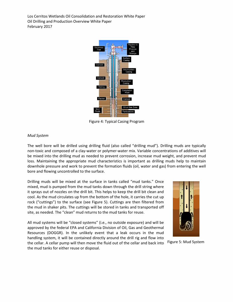
Well Casing Well drilling begins with installation of the conductor casing. Casing is the major structural component of the well. Once the conductor casing is set, a large drill bit is attached to a large diameter pipe and lowered through the conductor casing. Additional pipes are attached to add length. Once the conductor casing is cleared, drilling begins. As the bit drills deeper, additional drill pipe is added to maintain downward force (“drill strings”). When the desired depth is reached, the drill strings are removed and a large diameter pipe is inserted and lowered downhole and cemented in place. A well contains multiple intervals of casing concentrically placed within the previous casing run until the target depth is reached (see Figure 4). The cemented-in-place steel casing prevents the contamination of fresh water zones. Casing restricts the migration of fluids and serves as a barrier to prevent the transfer of fluids between underground layers. Given local variability in subsurface conditions, the cement utilized is carefully designed and laboratory tested in advance to ensure that all well design and regulatory requirements are met. To ensure adequacy of the seal between the casing and the cement, a cement bond log will be run and the results continuously monitored.
Los Cerritos Wetlands Oil Consolidation and Restoration White Paper Oil Drilling and Production Overview White Paper February 2017
Figure 4: Typical Casing Program
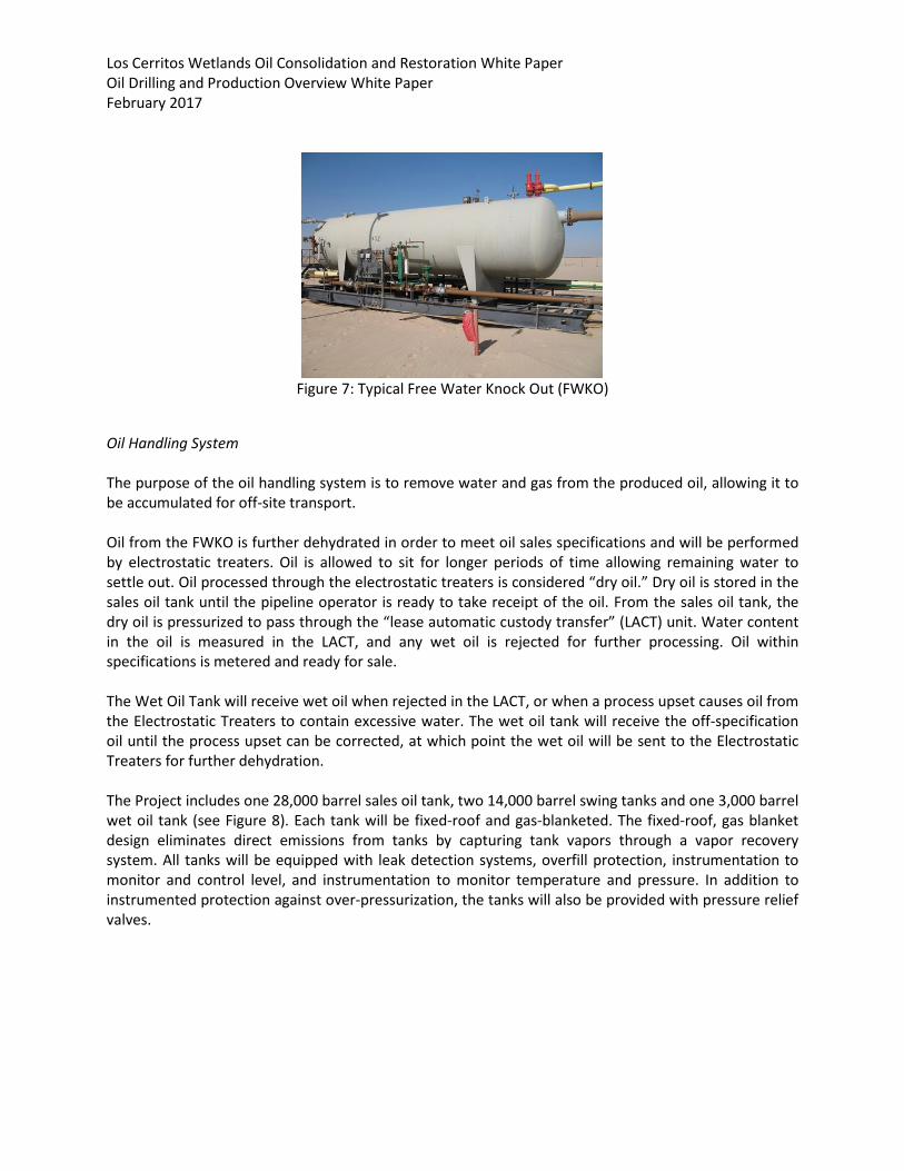
Mud System The well bore will be drilled using drilling fluid (also called “drilling mud”). Drilling muds are typically non-toxic and composed of a clay-water or polymer-water mix. Variable concentrations of additives will be mixed into the drilling mud as needed to prevent corrosion, increase mud weight, and prevent mud loss. Maintaining the appropriate mud characteristics is important as drilling muds help to maintain downhole pressure and work to prevent the formation fluids (oil, water and gas) from entering the well bore and flowing uncontrolled to the surface. Drilling muds will be mixed at the surface in tanks called “mud tanks.” Once mixed, mud is pumped from the mud tanks down through the drill string where it sprays out of nozzles on the drill bit. This helps to keep the drill bit clean and cool. As the mud circulates up from the bottom of the hole, it carries the cut up rock (“cuttings”) to the surface (see Figure 5). Cuttings are then filtered from the mud in shaker pits. The cuttings will be stored in tanks and transported off site, as needed. The “clean” mud returns to the mud tanks for reuse. All mud systems will be “closed systems” (i.e., no outside exposure) and will be approved by the federal EPA and California Division of Oil, Gas and Geothermal Resources (DOGGR). In the unlikely event that a leak occurs in the mud handling system, it will be contained directly around the drill rig and flow into the cellar. A cellar pump will then move the fluid out of the cellar and back into the mud tanks for either reuse or disposal.
Figure 5: Mud System

Los Cerritos Wetlands Oil Consolidation and Restoration White Paper Oil Drilling and Production Overview White Paper February 2017 Blowout Prevention Equipment System All wells will be equipped with Blowout Prevention Equipment (BOPE) systems. A BOPE system is a safety system used during drilling to prevent uncontrolled release of formation fluids, and allows for the shut off of flow to prevent spills and release of materials. The BOPE system is composed of a stack, actuation systems, a choke manifold, stop systems, and other equipment (see Figure 6). The BOPE has an independent back up system (the accumulator) which can be activated in the event the rig loses power. The BOPE system will be designed to handle the maximum possible pressure expected at the wellhead. BOPE specifications are set by the California DOGGR. BOPE is required on all wells in California and is dictated by maximum expected formation pressure and proximity to residences and/or commercial development. BOPEs will be tested in accordance with DOGGR specifications and witnessed as required in permits issued by DOGGR. Once the well is drilled, the BOPE will be replaced by a wellhead and Christmas tree. All equipment used will meet the American Petroleum Institute (API) standards, which are based on proven, sound engineering practices and safe materials.
Figure 6: Blow Out Prevention Equipment
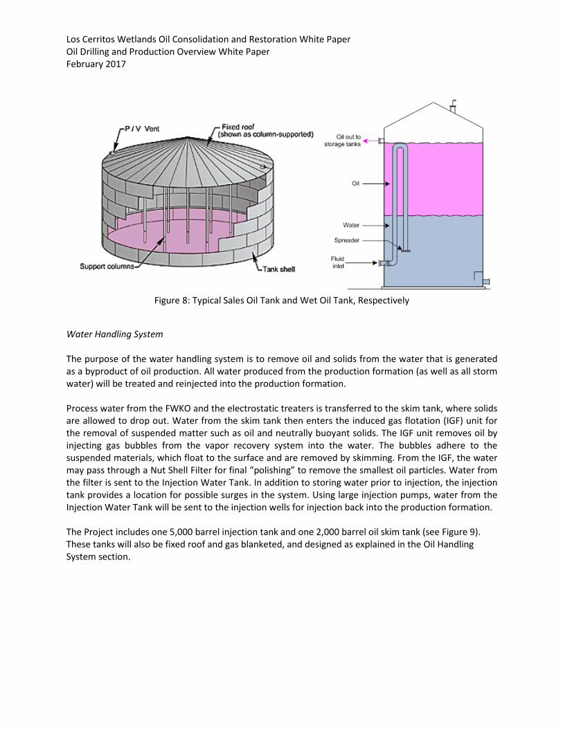
Oil Production Once the desired depth is reached and the well is completed, production can begin. During the oil extraction process, oil, water, and gas are brought to the surface from the production formation and separated. This is performed by three-phase separator pressure vessels (“free water knockouts, FWKO”) which utilize the difference in density between gas, oil and water to provide separation (see Figure 7). The oil handling, water handling and natural gas handling systems are explained below.
Los Cerritos Wetlands Oil Consolidation and Restoration White Paper Oil Drilling and Production Overview White Paper February 2017
Figure 7: Typical Free Water Knock Out (FWKO)
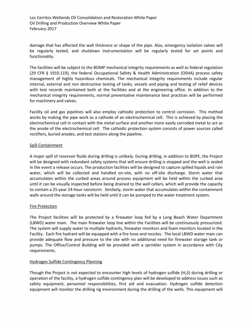
Oil Handling System The purpose of the oil handling system is to remove water and gas from the produced oil, allowing it to be accumulated for off-site transport. Oil from the FWKO is further dehydrated in order to meet oil sales specifications and will be performed by electrostatic treaters. Oil is allowed to sit for longer periods of time allowing remaining water to settle out. Oil processed through the electrostatic treaters is considered “dry oil.” Dry oil is stored in the sales oil tank until the pipeline operator is ready to take receipt of the oil. From the sales oil tank, the dry oil is pressurized to pass through the “lease automatic custody transfer” (LACT) unit. Water content in the oil is measured in the LACT, and any wet oil is rejected for further processing. Oil within specifications is metered and ready for sale. The Wet Oil Tank will receive wet oil when rejected in the LACT, or when a process upset causes oil from the Electrostatic Treaters to contain excessive water. The wet oil tank will receive the off-specification oil until the process upset can be corrected, at which point the wet oil will be sent to the Electrostatic Treaters for further dehydration. The Project includes one 28,000 barrel sales oil tank, two 14,000 barrel swing tanks and one 3,000 barrel wet oil tank (see Figure 8). Each tank will be fixed-roof and gas-blanketed. The fixed-roof, gas blanket design eliminates direct emissions from tanks by capturing tank vapors through a vapor recovery system. All tanks will be equipped with leak detection systems, overfill protection, instrumentation to monitor and control level, and instrumentation to monitor temperature and pressure. In addition to instrumented protection against over-pressurization, the tanks will also be provided with pressure relief valves.
Los Cerritos Wetlands Oil Consolidation and Restoration White Paper Oil Drilling and Production Overview White Paper February 2017
Figure 8: Typical Sales Oil Tank and Wet Oil Tank, Respectively
Water Handling System The purpose of the water handling system is to remove oil and solids from the water that is generated as a byproduct of oil production. All water produced from the production formation (as well as all storm water) will be treated and reinjected into the production formation. Process water from the FWKO and the electrostatic treaters is transferred to the skim tank, where solids are allowed to drop out. Water from the skim tank then enters the induced gas flotation (IGF) unit for the removal of suspended matter such as oil and neutrally buoyant solids. The IGF unit removes oil by injecting gas bubbles from the vapor recovery system into the water. The bubbles adhere to the suspended materials, which float to the surface and are removed by skimming. From the IGF, the water may pass through a Nut Shell Filter for final “polishing” to remove the smallest oil particles. Water from the filter is sent to the Injection Water Tank. In addition to storing water prior to injection, the injection tank provides a location for possible surges in the system. Using large injection pumps, water from the Injection Water Tank will be sent to the injection wells for injection back into the production formation. The Project includes one 5,000 barrel injection tank and one 2,000 barrel oil skim tank (see Figure 9). These tanks will also be fixed roof and gas blanketed, and designed as explained in the Oil Handling System section.

Los Cerritos Wetlands Oil Consolidation and Restoration White Paper Oil Drilling and Production Overview White Paper February 2017
Figure 9: Typical Skim Oil Tank and Injection Water Tank, Respectively
Natural Gas Handling System The purpose of the gas handling system is to gather produced gas and treat it to meet sales quality specifications. Gas compression is provided in two stages. Casing gas will combine with gases from the FWKO and the vapor recovery systems to be compressed for treatment. Once the gas meets pipeline specifications it will be further compressed and injected into the gas distribution system. In order to meet the CPUC sales specifications, heavy hydrocarbons and water must be removed from the gas stream using a combined refrigeration/dehydration system. This is accomplished using a Low Temperature Separator (LTS) and Glycol system. In the LTS, the gas is cooled to sub-zero temperatures, causing water and heavy hydrocarbons to condense where they can be removed in a two phase separator. Further dehydration is performed by injecting Triethylene Glycol (TEG) into the gas which has a high affinity for water. TEG and water are removed in another two phase separator. The TEG is recovered from the water by boiling, as it has a lower boiling point than water, and is then reused in the system. Sales quality gas will be transferred directly to a gas compression system. The processed gas is burned in gas turbines generating electricity to run on-site equipment. The Project will use four gas turbines, with a 4.6 MW rating, to generate power onsite (see also Power White Paper).1 Environmental Protection Oil drilling and production are heavily regulated in California,2 and the Project will adhere to all applicable rules and regulations. In addition to the various safety systems and environmental protections mentioned above, the Project includes numerous measures to protect the environment, summarized below.
1 See Power White Paper. 2 California Statutes and Regulations for Conservation of Oil, Gas and Geothermal Operations. Department of Conservation. Publication Number PRC10. April 2016. Website: ftp://ftp.consrv.ca.gov/pub/oil/laws/PRC10.pdf

Los Cerritos Wetlands Oil Consolidation and Restoration White Paper Oil Drilling and Production Overview White Paper February 2017 General Operation The Project will be equipped with computerized control, monitoring and communication systems. In general, these systems will be designed to monitor and control all process equipment that will operate within the facility. The operator console will be staffed 24-hours a day. The building will be provided with an uninterruptible power supply and a diesel emergency generator to provide continuous power in the event of an external power failure. It will also be equipped with gas and fire detection systems and a fire suppression system. The on-site Operations Building will house the operator console allowing the operator to interface with the Supervisory Control and Data Acquisition (SCADA) Systems. The SCADA system will provide continuous real-time, operational data for all wells and process systems, including temperature, pressure, and flow rates. Equipment status and condition will also be monitored, including the operational condition of wells, pumps, valves, compressors, etc. Information also available through the SCADA system will include security system status, intrusion detection alarms, remote video cameras, firefighting system status and alarms, leak detection and other facilities status and safety points. Automatic report generation systems will supply historical and current data to operations and maintenance personnel. The SCADA system will provide the ability to control systems operation from the Operations Building and respond to alarms that are initiated when operating conditions fall outside established parameters. Upon detection of a process upset, the Operator will have the capability to shut down the affected systems. The SCADA system will provide for a high degree of safety in the operation, allow for quick and technically sound responses to abnormal conditions, and simultaneously provide the basis for environmentally sensitive operating decisions. Equipment will typically be provided with independent automated shutdown instrumentation as well as remote indication with both pre-alarms and shutdowns, providing redundancy in safety systems. The SCADA system will have multiple levels of redundancy for critical operating components and applications, and has been designed to include cybersecurity measures. Inspection and Maintenance In addition to standard mill testing of all pipe and fittings, hydrostatic testing will be performed after construction and prior to startup. This test involves filling a test section of the pipeline with fresh water and increasing pressure to a predetermined level. Such tests are designed to prove that the pipe, fittings, and weld sections will maintain mechanical integrity under pressure without failure or leakage. The pipeline connecting the PP and LCWA sites is subject to Federal regulations (49 CFR Part 192 and 49 CFR Part 195) which mandate hydrostatic testing of new, cathodically protected pipelines prior to placing the pipeline into operation. Additionally, the connecting pipeline will be inspected in accordance with Department of Transportation requirements and state and federal regulations to help ensure the ongoing integrity of the pipeline. Other inspection and maintenance of the connecting pipeline may include the use of pigs, which are devices inserted into the pipeline. Pigs will be used as needed to clean and/or inspect the connecting pipeline and “smart pigs” will be used to detect corrosion or other
Los Cerritos Wetlands Oil Consolidation and Restoration White Paper Oil Drilling and Production Overview White Paper February 2017 damage that has affected the wall thickness or shape of the pipe. Also, emergency isolation valves will be regularly tested, and shutdown instrumentation will be regularly tested for set points and functionality. The facilities will be subject to the BOMP mechanical integrity requirements as well as federal regulation (29 CFR § 1910.119), the federal Occupational Safety & Health Administration (OSHA) process safety management of highly hazardous chemicals. The mechanical integrity requirements include regular internal, external and non destructive testing of tanks, vessels and piping and testing of relief devices with test records maintained both at the facilities and at the engineering office. In addition to the mechanical integrity requirements, normal preventative maintenance best practices will be performed for machinery and valves. Facility oil and gas pipelines will also employ cathodic protection to control corrosion. This method works by making the pipe work as a cathode of an electrochemical cell. This is achieved by placing the electrochemical cell in contact with the metal surface and another more easily corroded metal to act as the anode of the electrochemical cell. The cathodic protection system consists of power sources called rectifiers, buried anodes, and test stations along the pipeline. Spill Containment A major spill of reservoir fluids during drilling is unlikely. During drilling, in addition to BOPE, the Project will be designed with redundant safety systems that will ensure drilling is stopped and the well is sealed in the event a release occurs. The production facilities will be designed to capture spilled liquids and rain water, which will be collected and handled on-site, with no off-site discharge. Storm water that accumulates within the curbed areas around process equipment will be held within the curbed area until it can be visually inspected before being drained to the well cellars, which will provide the capacity to contain a 25-year 24-hour rainstorm. Similarly, storm water that accumulates within the containment walls around the storage tanks will be held until it can be pumped to the water treatment system. Fire Protection The Project facilities will be protected by a firewater loop fed by a Long Beach Water Department (LBWD) water main. The main firewater loop line within the Facilities will be continuously pressurized. The system will supply water to multiple hydrants, firewater monitors and foam monitors located in the Facility. Each fire hydrant will be equipped with a fire hose and nozzles. The local LBWD water main can provide adequate flow and pressure to the site with no additional need for firewater storage tank or pumps. The Office/Control Building will be provided with a sprinkler system in accordance with City requirements. Hydrogen Sulfide Contingency Planning Though the Project is not expected to encounter high levels of hydrogen sulfide (H2S) during drilling or operation of the facility, a hydrogen sulfide contingency plan will be developed to address issues such as safety equipment, personnel responsibilities, first aid and evacuation. Hydrogen sulfide detection equipment will monitor the drilling rig environment during the drilling of the wells. This equipment will

Los Cerritos Wetlands Oil Consolidation and Restoration White Paper Oil Drilling and Production Overview White Paper February 2017 include H2S monitors and alarms on the drilling rig and breathing air packs at the rig and in the safety trailer. Conclusion The proposed Los Cerritos Wetlands Oil Consolidation and Restoration Project includes the drilling and operation of new oil production, water injection and water source wells from the Pumpkin Patch and LCWA sites. The Project includes numerous safety systems and measures taken to protect the environment, and will adhere to all applicable rules and regulations.