oil examination of a failed boiler tube - steel...
TRANSCRIPT

Steel Image Inc. – Failure Analysis and Metallography 7 Innovation Dr. Suite 155, Flamborough, ON, L9H 7H9
[email protected], (905) 745-6429
EXAMINATION OF A FAILED BOILER TUBE
EXAMPLE REPORT
- Electronic Copy -
Shane Turcott, M.A.Sc. Principal Metallurgist
OVERVIEW & OUTCOME A boiler had experienced repetitive tube failures along a bend. Although previous analyses had been conducted, the root cause was not well understood. The examination found that tube corrosion fatigue cracking was secondary damage resulting from retaining bracket failures. Once several brackets had failed, the stresses at the remaining brackets increased, resulting in tube cracking. Therefore, to prevent future failures, modification to the retaining brackets would be required.

Example Report
Examination of a Failed Boiler Tube 1 of 13 6
EXAMINATION OF A FAILED BOILER TUBE
1.0 INTRODUCTION A portion of a failed boiler tube was submitted for analysis. The tube had cracked at a bend. This was the fourth time that such a bend location had failed and reports of these three historical failures were provided. Two of these failures had resulted from corrosion fatigue. This tube comprised of ¾ inch, schedule 40 ASME SA106 Grade B carbon steel tube. Discussion included that the boiler was aggressively ‘blown down’ and re-pressurized daily. Steel Image was requested to determine the nature of failure. 2.0 EXAMINATION 2.1 Visual / Macroscopic Examination Figure 1 displays the submitted sample. The as-received tube sample had been cut opened and grit blasted on both the internal and external surfaces, including at the cracked region. This had removed the service scale at the cracked region. On the sample provided, the convex side of the bend contained four bracket welds (Figure 2). Two of these four welds, including Weld #2 which contained the through cracks, had fractured. A third bracket weld, referred to as Weld #4, had also failed yet an overlying weld repair had been conducted (Figure 2e). These weld fractures exhibited significant corrosion and grit blast damage yet it was assumed failure had occurred from either fatigue and/or corrosion fatigue. Failure of these bracket welds indicated relatively high stresses/strains applied from the tube. As these brackets were intended to brace the tube bend during service, failure of these welds would have altered/increased the loading at the remaining welds. Based upon
SUMMARY Failure of the boiler tube was the result of corrosion fatigue cracking, starting at the inner diameter surfaces. Although oxidation from the treated water had been a contributor, the primary cause of cracking was due to elevated, cyclic loading. Three of the four retaining bracket welds intended to distribute the expansion loading of the bend had failed (one had been repaired). This indicated that the overall bend had experienced high cyclic loading. It was theorized that failure of the bracket welds had resulted in increased loading on the remaining weld joints, causing corrosion fatigue cracking of the tube. Therefore, tube failure was likely secondary damage after bracket failure.

Example Report
Examination of a Failed Boiler Tube 2 of 13 6
further analysis, it was plausible that sequential failure of the bracket welds had contributed to tube cracking. Weld #1 exhibited no cracks and, had this weld failed first, would have increased the loading at Weld #2, promoting the initiation of corrosion fatigue. Weld #3 would later be found to also contain a large crack, potentially explained as consequence of failures of both Welds #1 and #2. Tube cracking had occurred at a bracket weld (referred to as Weld #2) on the convex side of the bend. Two large, aligned cracks initiated at the inner diameter surface beneath the bracket weld. Both cracks had propagated through the tube wall and the bracket weld (Figure 3). These two cracks were opened for examination and the cracks’ surfaces are illustrated in Figure 4. Crack initiation had occurred on the inner diameter surface. The cracks’ features were quite dark and further examination would find these surfaces had been oxidized. No significant pitting or irregular, contributing features were observed on the inner diameter surface at the initiation sites. A third, small crack was also observed adjacent the two through cracks, indicated in Figure 4. 2.2 SEM Examination and EDS Analysis SEM examination of the through cracks surfaces confirmed the loss of micro-fracture features due to corrosion/oxidation (Figure 5). Energy dispersive spectroscopy (EDS) analysis found the surface to comprise of iron oxide (Figure 6). No corrosion agents were detected. Ultimately, crack growth was in part driven by oxidation from the contained water. 2.3 Optical Microscopy Bracket Welds #1, #2 and #3, which included the through crack at Weld #2, were longitudinally cross-sectioned and prepared for optical examination. A longitudinal, two inch long section was also cross-sectioned from between Welds #2 and #3. The core tube material comprised of equaixed ferrite and lamellar pearlite at all locations examined remote the welds (Figure 7). The microstructure was typical for the as-supplied condition of ASME SA106 grade B steel. No thermal degradation of the core material was observed to indicate abnormal temperatures during service. No cracks had formed at Weld #1, Weld #2 exhibited the primary through cracks and a large crack had formed at Weld #3. Although a few other shallow cracks had formed, no other significant cracks were observed on the metallographic specimens including the section from between the bracket welds. Figure 8 displays macrographs of the three welds. Examination of the cross-sectioned through crack found the crack to have been located within the heat affected zone of the weld. The crack itself was rather straight with only limited branching (Figure 9). The entire length of the crack, including the branches,

Example Report
Examination of a Failed Boiler Tube 3 of 13 6
consisted of an oxide layer. The crack morphology and features were consistent with corrosion fatigue. The location selected to cross-section Weld #3 was chosen at the edge of the weld due to a feature of interest suspected as being a crack (initially unclear due to the grit blasting). Optical examination did confirm this to be a crack which also exhibited features typical of a corrosion fatigue crack (Figure 10). Oxides were present at the crack tip which was classic to corrosion fatigue formed between loading cycles. The crack was measured to an approximate depth of 1.5mm (0.060 inches). At the location cross-sectioned, the bracket weld heat affected zone had not extended through to the inner diameter. 2.4 Hardness Testing Microhardness testing of the tube was conducted on the (a) core material and at the inner diameter surfaces adjacent (b) a through crack at Weld #2 and (c) the large crack found at Weld #3. Testing was conducted in accordance with ASTM E384 using a 500gf load. Table 1 lists the obtained results. No abnormalities with the material hardness were observed. Table 1: Microhardness Test Results
Location Measurements
(HV500gf) Avg. Hardness
HV500gf HRB
Remote, Core Material 175, 169, 170, 172, 170 171 87
Primary Crack, ID surface (within weld HAZ)
199, 205, 197, 202, 207 202 93
Crack at Weld #3, Initiation/ ID surface
167, 178, 168, 173, 168 171 87
3.0 DISCUSSION Cracking of the boiler tube was the result of corrosion fatigue. Crack growth had occurred from repetitive cycles of (a) oxidation at the crack tip followed by (b) a loading cycle cracking the oxides, exposing fresh metal at the crack tip. The loading cycles were likely from either thermal or pressure changes, resulting in the bend experiencing straightening stresses/strains. Although oxidation had acted as a contributing mechanism to crack formation/growth, its contribution was likely secondary compared to the cyclic stresses/strains during service. Therefore, the primary factor leading to failure was the amplitude of the cyclic straightening strains experienced at the bend. Such loading conditions could match with regular, aggressive ‘blowing down’ and daily re-pressurizing of the system. It was theorized that the corrosion fatigue was secondary damage occurring after failure of several retaining bracket welds. Failure of these brackets would have altered the stresses experienced at the remaining brackets, increasing the local stresses/strains and

Example Report
Examination of a Failed Boiler Tube 4 of 13 6
promoting corrosion fatigue. Weld #1 exhibited no cracks and, had this weld failed first, would have increased the loading at Weld #2, promoting the initiation of corrosion fatigue. Whether prevention of these weld failures would have avoided tube cracking was unclear. After weld failure, the remaining bracket would have experienced increasing loading under straightening loading/stresses (ie. thermal expansion or pressure fluctuations). Therefore, it remains likely that the tube cracking was secondary damage occurring after bracket failure. The mechanism causing failure of the bracket welds could not be conclusively determined due to the corrosion and grit blasting. Yet it was assumed that failure of these bracket welds occurred by either fatigue or corrosion fatigue. In either case, the same cyclic stresses causing straightening of the bend and tube cracking had likely caused failure of these brackets welds. Failure of these welds further indicated that this bend experienced relatively high loading conditions during service. The tube material appeared to be typical of ASME SA106 Grade B steel. No quality issues were suspected as having contributed to failure. No thermal microstructural degradation to the core material was observed to suggest abnormal temperatures in operation. Ultimately, tube cracking was associated as secondary damage to failure of the retaining brackets. The daily blow down and re-pressurization resulted in a high number of cyclic loads applied on the bend, likely beyond what the boiler was designed for. It is recommended that review of the retaining bracket design be conducted. 4.0 CONCLUSIONS Failure of the boiler tube was the result of corrosion fatigue cracking. By this mechanism, two through cracks had initiated at a failed bracket weld. Although oxidation from the treated water had been a contributor, the primary cause of cracking was likely from elevated cyclic loading at the cracked location from thermal expansion and/or pressure changes. Such loading conditions could match with regular, aggressive ‘blowing down’ and daily re-pressurizing of the system. The tube also had experienced failure of two other retaining bracket welds (one having been repaired). These brackets were intended to brace the tube during expansion. Therefore, failure of these welds may have increased the loading experienced at the remaining welds. It was likely that the tube corrosion fatigue cracks had initiated after failure of the neighbouring bracket weld and as a result of bearing increasing loading. Another bracket weld, adjacent two failed bracket welds, also exhibited a large, 1.5mm deep crack. Therefore, tube cracking was likely secondary damage occurring after failure of the retaining brackets. It is recommended that the design of the retaining brackets be reviewed.

Example Report
Examination of a Failed Boiler Tube 5 of 13 6
Figure 1: Photographs displaying the submitted portions of the cracked tube. The
location of through-cracking is indicated. Two through cracks had formed at a failed bracket weld.
Through Crack
Example Report
Examination of a Failed Boiler Tube 6 of 13 6
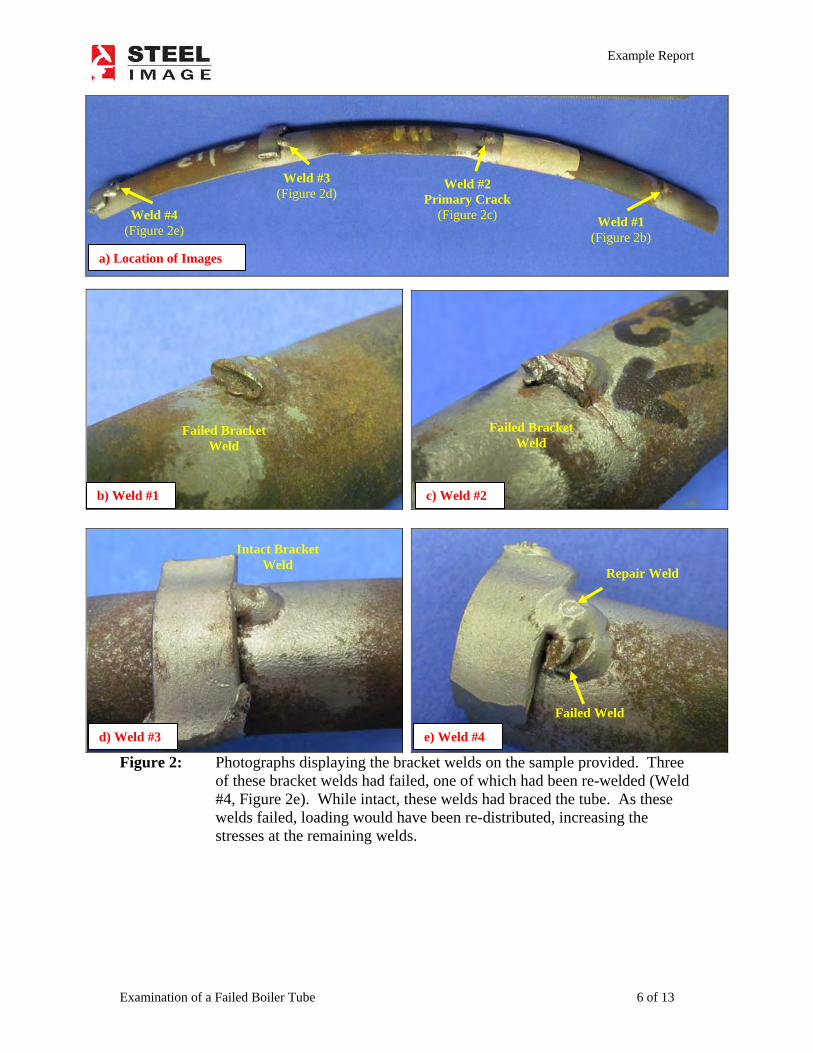
Figure 2: Photographs displaying the bracket welds on the sample provided. Three
of these bracket welds had failed, one of which had been re-welded (Weld #4, Figure 2e). While intact, these welds had braced the tube. As these welds failed, loading would have been re-distributed, increasing the stresses at the remaining welds.
a) Location of Images
b) Weld #1 c) Weld #2
d) Weld #3 e) Weld #4
Failed Weld
Repair Weld
Failed Bracket Weld
Failed Bracket Weld
Intact Bracket Weld
Weld #1 (Figure 2b)
Weld #2 Primary Crack
(Figure 2c)
Weld #3 (Figure 2d)
Weld #4 (Figure 2e)

Example Report
Examination of a Failed Boiler Tube 7 of 13 6
Figure 3: Photographs displaying the primary cracks under investigation. Two
through cracks had formed at a retaining bracket weld. Note that the internal and internal surfaces had been grit blasted. Further examination would find that cracking had initiated on the inner diameter surface.
a) Outer Diameter
b) Inner Diameter, As-Received
c) Inner Diameter, After Cleaning

Example Report
Examination of a Failed Boiler Tube 8 of 13 6
Figure 4: Photographs displaying the two, opened through cracks. Crack initiation
of both cracks occurred along the inner diameter surface. A small, third crack was also present adjacent these two cracks. The crack surfaces were quite dark as a result of oxidation/corrosion.
Initiation Initiation
Small Crack
a) ID Surface
b) Opened Crack, Side #1
c) Opened Crack, Side #2
Initiation Initiation

Example Report
Examination of a Failed Boiler Tube 9 of 13 6
Figure 5: SEM images of the opened cracks’ surfaces. Both crack surfaces
comprised of oxidation. SE1, 20kV.
Crack #1 Initiation (Figure 5b,c)
Crack #1 OD (Figure 5d)
Crack #2 Initiation
(Figure 5e,f)
a) Location of Images
b) Crack #1, ID, 50x
c) Crack #1, ID, 2000x d) Crack #1, OD,
e) Crack #2, ID, 50x f) Crack #2, ID, 2000x
Oxidized / Corroded
Oxidized / Corroded
Oxidized / Corroded

Example Report
Examination of a Failed Boiler Tube 10 of 13 6
Figure 6: Examples of EDS spectra taken from the initiation regions of the two
through cracks. Both fracture surfaces comprised of iron oxide. No abnormal corrosion elements or suspected corrosion agents were detected. SE1, 20kV.
Figure 7: Micrographs displaying the tube core material near the through cracks,
remote the weld HAZ. The core structure of ferrite and lamellar pearlite was typical for the as-supplied condition of ASME SA106 Grade B steel. No thermal degradation in service had occurred. Etched using 3% nital.
a) Core Tube, 400x b) Core Tube, 1000x
Crack #1, ID, 50x
Crack #2, ID, 50x

Example Report
Examination of a Failed Boiler Tube 11 of 13 6
Figure 8: Macrographs displaying cross-sections of three bracket welds. As well as
the primary through cracks at Weld #2, a 1.5mm deep crack had also formed at Weld #3. After failure of the bracket welds, the loading in the tube metal at the remaining bracket welds would have changed/increased.
a) Location of Images
Weld #1 (no cracks) (Figure 8b)
Weld #2 Primary Crack
(Figure 8c)
Weld #3 (large crack) (Figure 8d,e)
b) Weld #1 c) Weld #2
d) Weld #3, Location of Cut e) Weld #3
Primary Through Crack
Large Crack
Example Report
Examination of a Failed Boiler Tube 12 of 13 6
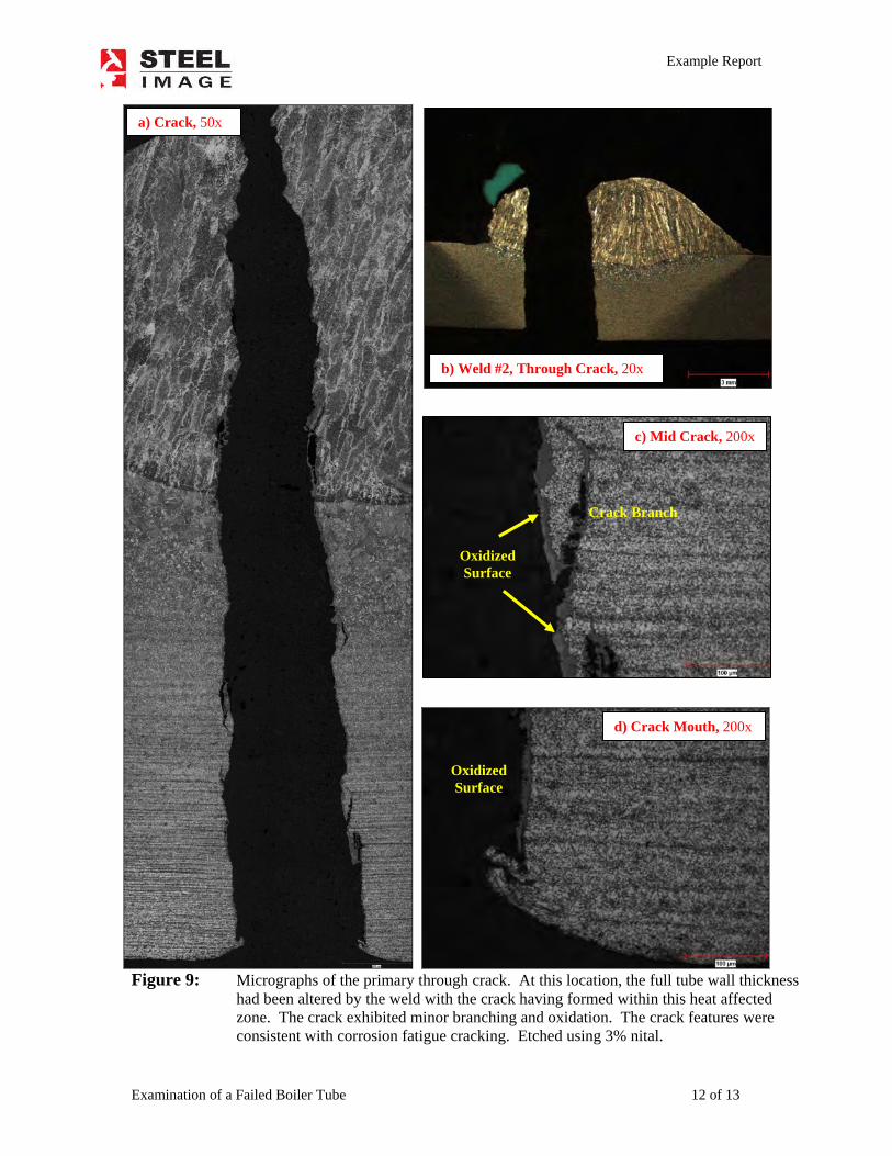
Figure 9: Micrographs of the primary through crack. At this location, the full tube wall thickness
had been altered by the weld with the crack having formed within this heat affected zone. The crack exhibited minor branching and oxidation. The crack features were consistent with corrosion fatigue cracking. Etched using 3% nital.
a) Crack, 50x
b) Weld #2, Through Crack, 20x
c) Mid Crack, 200x
d) Crack Mouth, 200x
Crack Branch
Oxidized Surface
Oxidized Surface

Example Report
Examination of a Failed Boiler Tube 13 of 13 6
Figure 10: Micrographs of the corrosion fatigue crack at Weld #3. It was theorized
that after failure of the Bracket Welds #1 and #2, loading at this weld would have been increased, promoting corrosion fatigue. Etched using 3% nital.
Oxidation at crack tip
b) Weld #3, 20x
a) Crack, 100x
c) Crack Tip, 400x
d) Crack Mouth, 400x
Oxidation