oil mist detectors vn115/93 vn116/93 vn215/93 …€¦ · oil mist detectors vn115/93 vn116/93...
TRANSCRIPT
Operation Manual Part-No. 10980
Version 2.3, 07/2015
VISATRON®
Oil Mist Detectors
VN115/93
VN116/93 VN215/93
IACS UR M67 type approved
Operation Manual VISATRON® series VN93 07/2015
Page 2
SCHALLER AUTOMATION D-66440 Blieskastel / Saarland / Germany / Industriering 14 / P.O Box 1280
Industrielle Automationstechnik GmbH & Co. KG Tel. +49(0)6842-508-0 / Fax -260 / eMail: [email protected] / www.schaller.de
About this Manual
This manual was designed to answer your questions concerning the handling, operation and maintenance of the Oil Mist Detector (OMD) VISATRON® series
VN93. The operating instructions are applicable for:
VN115/93
VN116/93 VN215/93
Should you encounter any interruption or breakdown of your VISATRON® series OMD device during operation, please contact your local representative (refer to
chapter 10 ‘Service Partners’) or SCHALLER AUTOMATION Industrielle Automationstechnik GmbH & Co. KG directly. The repair of OMD devices may only be carried out by authorized repair centres. You can expect safe and reliable
operation of your OMD only when the device is operated in accordance with this manual.
Please take note of the following:
Please read this manual thoroughly and acquaint yourself with the correct installation, operation and maintenance of your VISATRON® series VN93 device.
Installations of the VISATRON® series VN93 devices have to be in accordance to the IACS UR M10 if applicable.
Use the VISATRON® series VN93 devices only for the purpose described in the
operation manual. Incorrect maintenance and handling errors may cause possible device failure or
an unsafe operating environment. The VISATRON® series VN93 devices may only be used by authorised staff.
This operation manual must be available at the place of installation at all times. Terms and conditions of sale
The standard terms and conditions of sale of SCHALLER AUTOMATION shall apply to all VISATRON® and related products.
SCHALLER AUTOMATION Industrielle Automationstechnik GmbH & Co. KG warrants that under proper use, handling and maintenance OMD VISATRON® series VN93 is
free from defects in material, design and/or workmanship. Claims of buyers/operators, in particular compensation for damage, which does not arise at
OMD VISATRON® series VN93 itself or for natural wear and tear of consumable supplies, e.g. filters etc., are excluded. SCHALLER AUTOMATION Industrielle Automationstechnik GmbH & Co. KG is not responsible for defects which arise as a
result of:
a) natural wear and tear, improper commissioning, improper use/handling, use of unsuitable power supply, welding processes on the engine as well as non-observance of commissioning, installation, operating and service instructions as
given in this Operation Manual
Operation Manual VISATRON® series VN93 07/2015
Page 3
SCHALLER AUTOMATION D-66440 Blieskastel / Saarland / Germany / Industriering 14 / P.O Box 1280
Industrielle Automationstechnik GmbH & Co. KG Tel. +49(0)6842-508-0 / Fax -260 / eMail: [email protected] / www.schaller.de
b) components and design other than the OMD VISATRON® series VN93
c) alterations or modifications of the OMD VISATRON® series VN93 carried out by
the buyer/operator or third parties without written authorization of SCHALLER AUTOMATION Industrielle Automationstechnik GmbH & Co. KG
d) incorrect combination of devices and/or components or operation of devices and/or components which are not certified to be compatible or not permitted by the manufacturer - SCHALLER AUTOMATION Industrielle Automationstechnik
GmbH & Co. KG
Operation Manual VISATRON® series VN93 07/2015
Page 4
SCHALLER AUTOMATION D-66440 Blieskastel / Saarland / Germany / Industriering 14 / P.O Box 1280
Industrielle Automationstechnik GmbH & Co. KG Tel. +49(0)6842-508-0 / Fax -260 / eMail: [email protected] / www.schaller.de
Safety instructions
The series VN93 devices are manufactured according to the high quality standards of SCHALLER AUTOMATION and must pass stringent factory tests. In order to keep
the device operating reliable and trouble free, the user has to take note of the safety hints and warnings. In the instruction manual they are marked with the following symbols.
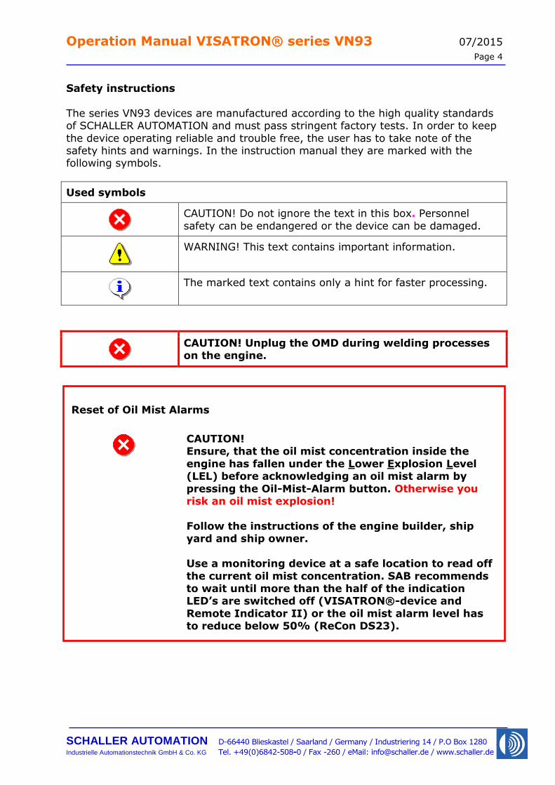
Used symbols
CAUTION! Do not ignore the text in this box. Personnel
safety can be endangered or the device can be damaged.
WARNING! This text contains important information.
The marked text contains only a hint for faster processing.
CAUTION! Unplug the OMD during welding processes on the engine.
Reset of Oil Mist Alarms
CAUTION! Ensure, that the oil mist concentration inside the
engine has fallen under the Lower Explosion Level (LEL) before acknowledging an oil mist alarm by
pressing the Oil-Mist-Alarm button. Otherwise you risk an oil mist explosion!
Follow the instructions of the engine builder, ship yard and ship owner.
Use a monitoring device at a safe location to read off
the current oil mist concentration. SAB recommends to wait until more than the half of the indication LED’s are switched off (VISATRON®-device and
Remote Indicator II) or the oil mist alarm level has to reduce below 50% (ReCon DS23).
Operation Manual VISATRON® series VN93 07/2015
Page 5
SCHALLER AUTOMATION D-66440 Blieskastel / Saarland / Germany / Industriering 14 / P.O Box 1280
Industrielle Automationstechnik GmbH & Co. KG Tel. +49(0)6842-508-0 / Fax -260 / eMail: [email protected] / www.schaller.de
EC Declaration of Conformity
We, the manufacturer
SCHALLER AUTOMATION Industrielle Automationstechnik GmbH & Co. KG
Industriering 14
D-66440 Blieskastel
Germany
Tel.: 06842 / 508-0
Fax: 06842 / 508-260
declare on our own responsibility, that the product:
Kind of equipment: Oil Mist Detector
Type-designation: VISATRON® VN115/93
VISATRON® VN116/93
VISATRON® VN215/93
to which this declaration relates exclusively used for the detection and signalizing of oil mist
in diesel aggregates and complies with the following EG-directives
Machinery directive 2006/42/EG
EMC directive 2004/108/EC
is in compliance with following standards:
EN ISO 4414
EN 60529
EN 55022
EN 61000-part 6-1 till 6-4
EN ISO 12100
CSPRI 16-1
CSPRI 16-2
CSPRI 16-4
IACS UR M67
A technical documentation is completely available. The operating manual
according to the oil mist detectors is available in the original version.
D-66440 Blieskastel, 2012/08/02
Stephan Schaller
- Managing Director -
Operation Manual VISATRON® series VN93 07/2015
Page 6
SCHALLER AUTOMATION D-66440 Blieskastel / Saarland / Germany / Industriering 14 / P.O Box 1280
Industrielle Automationstechnik GmbH & Co. KG Tel. +49(0)6842-508-0 / Fax -260 / eMail: [email protected] / www.schaller.de
Table of Contents
1 Introduction and functional overview ............................... 8
2 Installation instructions .................................................. 12
2.1 Mechanical installation ........................................................ 12
2.1.1 Basics .................................................................................12
2.1.2 Pipe dimensions ...................................................................16
2.1.3 Installation of pipe siphons ....................................................17
2.1.4 Installation of the siphon block connection units .......................19
2.1.5 Suction funnels in the crankcase compartment ........................20
2.1.6 Pipe arrangement at valve box (VN215/93 system only) ...........21
2.1.7 Compressed air connection ....................................................22
2.2 Electrical installation ........................................................... 23
2.2.1 VISATRON® series VN93 device.............................................23
2.2.2 Connection of monitoring devices ...........................................26
2.2.3 Schematic electrical wiring diagram ........................................28
3 Commissioning ................................................................ 29
3.1 Adjusting or checking the suction pressure ......................... 29
3.2 Filling of siphon blocks VN280plus of VN215/93 system with oil ........................................................................................ 30
3.3 Filling of siphon blocks VN180 for VN115/93 and VN116/93 system with oil .................................................................... 32
3.4 Filling of pipe siphons for VN115/93 and VN116/93 system
with oil ................................................................................ 33
3.5 Adjusting the sensitivity of the OMD .................................... 34
3.6 Commissioning check list ..................................................... 35
4 Operating instructions ..................................................... 36
4.1 Display ................................................................................. 36
4.2 Parameter Adjustment ......................................................... 38
4.3 Diagnostics .......................................................................... 39
4.4 Reset of Oil Mist Alarms ....................................................... 41
5 Troubleshooting .............................................................. 42
5.1 Clean infrared filter.............................................................. 43
5.2 Exchange air filters in the measuring head .......................... 43
5.3 Exchange air filter in pressure regulator unit ...................... 44
Operation Manual VISATRON® series VN93 07/2015
Page 7
SCHALLER AUTOMATION D-66440 Blieskastel / Saarland / Germany / Industriering 14 / P.O Box 1280
Industrielle Automationstechnik GmbH & Co. KG Tel. +49(0)6842-508-0 / Fax -260 / eMail: [email protected] / www.schaller.de
5.4 Exchange measuring head ................................................... 45
5.5 Measuring head fuses .......................................................... 46
6 Maintenance procedures ................................................. 47
7 Functional test ................................................................ 48
7.1 On board test ....................................................................... 48
7.2 Factory test at engine builder with smoke generator on
VN115/93 and VN116/93 installations ................................ 50
7.3 Additional pressure measurement on VN115/93 and VN116/93 installations ........................................................ 51
7.4 Factory test at engine builder with fog machine on VN215/93 installations ......................................................................... 53
8 Spare Parts and Accessories ............................................ 55
9 Technical data ................................................................. 61
10 Service Partners .............................................................. 66

Operation Manual VISATRON® series VN93 07/2015
Page 8
SCHALLER AUTOMATION D-66440 Blieskastel / Saarland / Germany / Industriering 14 / P.O Box 1280
Industrielle Automationstechnik GmbH & Co. KG Tel. +49(0)6842-508-0 / Fax -260 / eMail: [email protected] / www.schaller.de
1 Introduction and functional overview
The VISATRON® series VN93 Oil Mist Detector (OMD) from SCHALLER AUTOMATION protects large diesel engines against oil mist explosion caused by
spontaneously occurring oil mist. It is part of a safety system that helps protect operating personnel and prevents heavy damages to the engine.
This device conforms to the IACS UR M10 which is valid since January 2006.
It is not possible to directly monitor all potential sources of oil mist inside a large diesel engine. There are main bearings, large end bearings, pistons, liners, sliders, pumps, camshaft bearings, chains, gears or even tools left behind from installation
– all of these parts could produce oil mist e.g. in case of lubrication problems. Therefore the philosophy of SCHALLER AUTOMATION is that only OMD-systems can
securely prevent oil mist explosions by detecting the primary origin of danger: the oil mist itself.
The VISATRON® series VN93 OMD-System uses the approved wear-free suction system to continuously extract the atmosphere of the crankcase compartments and
other engine locations. The system works actively and is not waiting for oil mist clouds. This ensures proper reaction times from the beginning of oil mist generation to an oil mist alarm.
To avoid false alarms caused by splash oil the suction system makes use of
Schaller's special suction funnels working independent of the rotation sense of the engine. Additional draining components ensure correct working under all operating conditions. This includes the application in power plants as well as on vessels with
their static or dynamic inclinations. False alarms initiated by condensing water vapour are prevented by an integrated heater inside the measuring head housing.
The OMD-System consists of following parts:
VISATRON® series VN93 oil mist detector Protection cover
Suction system including pressure regulator Monitoring device
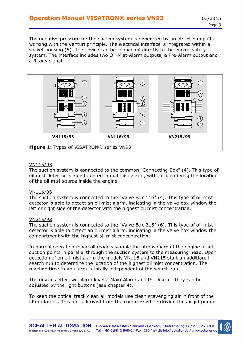
Three different types of the VISATRON® series VN93 oil mist detectors are available (see Figure 1):
VN115/93
VN116/93 VN215/93
All devices have a measuring head (2) which includes the optical measuring track under the control cover (3), a label on the front side and a display to give the user
all important information for normal operations conditions. The measuring head is mounted on a vibration protected base plate.
Operation Manual VISATRON® series VN93 07/2015
Page 9
SCHALLER AUTOMATION D-66440 Blieskastel / Saarland / Germany / Industriering 14 / P.O Box 1280
Industrielle Automationstechnik GmbH & Co. KG Tel. +49(0)6842-508-0 / Fax -260 / eMail: [email protected] / www.schaller.de
The negative pressure for the suction system is generated by an air jet pump (1) working with the Venturi principle. The electrical interface is integrated within a
socket housing (5). The device can be connected directly to the engine safety system. The interface includes two Oil-Mist-Alarm outputs, a Pre-Alarm output and
a Ready signal.
VN115/93 VN116/93 VN215/93
Figure 1: Types of VISATRON® series VN93
VN115/93 The suction system is connected to the common "Connecting Box" (4). This type of
oil mist detector is able to detect an oil mist alarm, without identifying the location of the oil mist source inside the engine.
VN116/93 The suction system is connected to the "Valve Box 116" (4). This type of oil mist
detector is able to detect an oil mist alarm, indicating in the valve box window the left or right side of the detector with the highest oil mist concentration.
VN215/93 The suction system is connected to the "Valve Box 215" (6). This type of oil mist
detector is able to detect an oil mist alarm, indicating in the valve box window the compartment with the highest oil mist concentration.
In normal operation mode all models sample the atmosphere of the engine at all suction points in parallel through the suction system to the measuring head. Upon
detection of an oil mist alarm the models VN116 and VN215 start an additional search run to determine the location of the highest oil mist concentration. The
reaction time to an alarm is totally independent of the search run. The devices offer two alarm levels: Main-Alarm and Pre-Alarm. They can be
adjusted by the light buttons (see chapter 4).
To keep the optical track clean all models use clean scavenging air in front of the filter glasses. This air is derived from the compressed air driving the air jet pump.
Operation Manual VISATRON® series VN93 07/2015
Page 10
SCHALLER AUTOMATION D-66440 Blieskastel / Saarland / Germany / Industriering 14 / P.O Box 1280
Industrielle Automationstechnik GmbH & Co. KG Tel. +49(0)6842-508-0 / Fax -260 / eMail: [email protected] / www.schaller.de
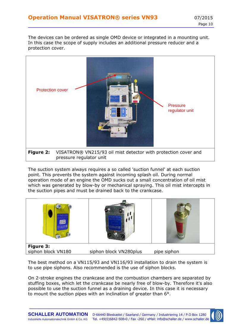
The devices can be ordered as single OMD device or integrated in a mounting unit. In this case the scope of supply includes an additional pressure reducer and a
protection cover.
Figure 2: VISATRON® VN215/93 oil mist detector with protection cover and pressure regulator unit
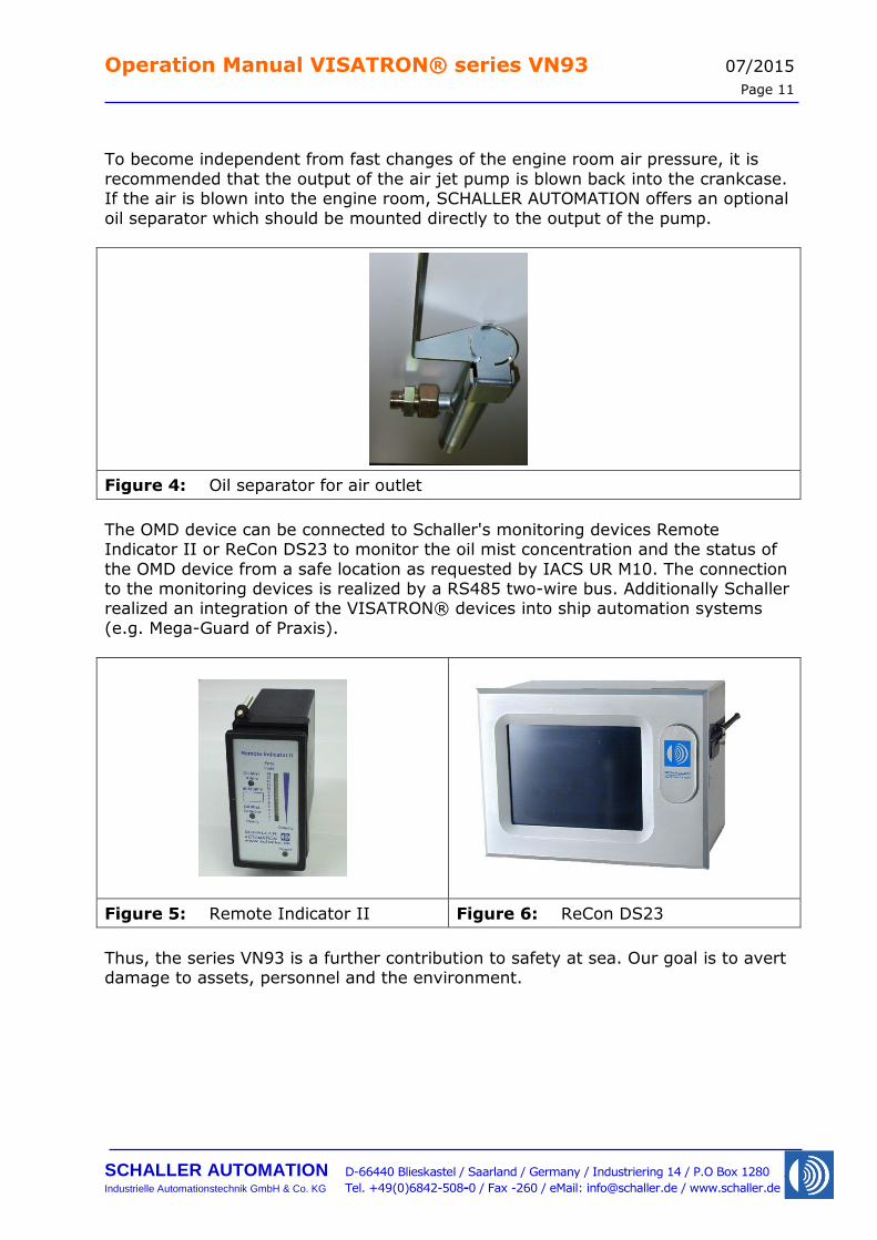
The suction system always requires a so called 'suction funnel' at each suction
point. This prevents the system against incoming splash oil. During normal operation mode of an engine the OMD sucks out a small concentration of oil mist which was generated by blow-by or mechanical spraying. This oil mist intercepts in
the suction pipes and must be drained back to the crankcase.
Figure 3: siphon block VN180 siphon block VN280plus pipe siphon
The best method on a VN115/93 and VN116/93 installation to drain the system is to use pipe siphons. Also recommended is the use of siphon blocks.
On 2-stroke engines the crankcase and the combustion chambers are separated by
stuffing boxes, which let the crankcase be nearly free of blow-by. Therefore it's also possible to use the suction funnel as a draining device. In this case it is necessary to mount the suction pipes with an inclination of greater than 6°.
Protection cover
Pressure regulator unit
Operation Manual VISATRON® series VN93 07/2015
Page 11
SCHALLER AUTOMATION D-66440 Blieskastel / Saarland / Germany / Industriering 14 / P.O Box 1280
Industrielle Automationstechnik GmbH & Co. KG Tel. +49(0)6842-508-0 / Fax -260 / eMail: [email protected] / www.schaller.de
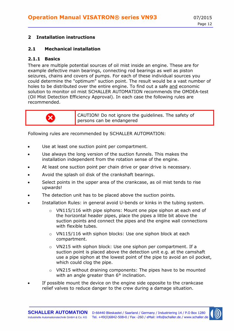
To become independent from fast changes of the engine room air pressure, it is
recommended that the output of the air jet pump is blown back into the crankcase. If the air is blown into the engine room, SCHALLER AUTOMATION offers an optional
oil separator which should be mounted directly to the output of the pump.
Figure 4: Oil separator for air outlet
The OMD device can be connected to Schaller's monitoring devices Remote Indicator II or ReCon DS23 to monitor the oil mist concentration and the status of
the OMD device from a safe location as requested by IACS UR M10. The connection to the monitoring devices is realized by a RS485 two-wire bus. Additionally Schaller realized an integration of the VISATRON® devices into ship automation systems
(e.g. Mega-Guard of Praxis).
Figure 5: Remote Indicator II Figure 6: ReCon DS23
Thus, the series VN93 is a further contribution to safety at sea. Our goal is to avert damage to assets, personnel and the environment.
Operation Manual VISATRON® series VN93 07/2015
Page 12
SCHALLER AUTOMATION D-66440 Blieskastel / Saarland / Germany / Industriering 14 / P.O Box 1280
Industrielle Automationstechnik GmbH & Co. KG Tel. +49(0)6842-508-0 / Fax -260 / eMail: [email protected] / www.schaller.de
2 Installation instructions
2.1 Mechanical installation
2.1.1 Basics
There are multiple potential sources of oil mist inside an engine. These are for example defective main bearings, connecting rod bearings as well as piston seizures, chains and covers of pumps. For each of these individual sources you
could determine the "optimum" suction point. The result would be a vast number of holes to be distributed over the entire engine. To find out a safe and economic
solution to monitor oil mist SCHALLER AUTOMATION recommends the OMDEA-test (Oil Mist Detection Efficiency Approval). In each case the following rules are recommended.
CAUTION! Do not ignore the guidelines. The safety of
persons can be endangered
Following rules are recommended by SCHALLER AUTOMATION:
Use at least one suction point per compartment.
Use always the long version of the suction funnels. This makes the installation independent from the rotation sense of the engine.
At least one suction point per chain drive or gear drive is necessary.
Avoid the splash oil disk of the crankshaft bearings.
Select points in the upper area of the crankcase, as oil mist tends to rise
upwards!
The detection unit has to be placed above the suction points.
Installation Rules: in general avoid U-bends or kinks in the tubing system.
o VN115/116 with pipe siphons: Mount one pipe siphon at each end of the horizontal header pipes, place the pipes a little bit above the
suction points and connect the pipes and the engine wall connections with flexible tubes.
o VN115/116 with siphon blocks: Use one siphon block at each
compartment.
o VN215 with siphon block: Use one siphon per compartment. If a
suction point is placed above the detection unit e.g. at the camshaft use a pipe siphon at the lowest point of the pipe to avoid an oil pocket, which could clog the pipe.
o VN215 without draining components: The pipes have to be mounted with an angle greater than 6° inclination.
If possible mount the device on the engine side opposite to the crankcase relief valves to reduce danger to the crew during a damage situation.
Operation Manual VISATRON® series VN93 07/2015
Page 13
SCHALLER AUTOMATION D-66440 Blieskastel / Saarland / Germany / Industriering 14 / P.O Box 1280
Industrielle Automationstechnik GmbH & Co. KG Tel. +49(0)6842-508-0 / Fax -260 / eMail: [email protected] / www.schaller.de
If possible place the VISATRON® detection unit in the center of the engine to avoid long pipe runs.
Select only suction points which allow the use of long suction funnels. In this case the installation side is independent from the rotation sense of the
engine. Installations without any suction funnels are not allowed.
If recommended by engine builder, determine an additional suction point at the camshaft bed.
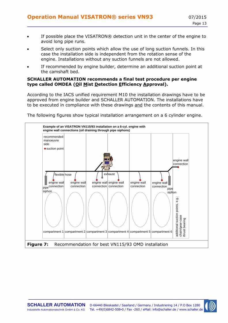
SCHALLER AUTOMATION recommends a final test procedure per engine type called OMDEA (Oil Mist Detection Efficiency Approval).
According to the IACS unified requirement M10 the installation drawings have to be approved from engine builder and SCHALLER AUTOMATION. The installations have
to be executed in compliance with these drawings and the contents of this manual.
The following figures show typical installation arrangement on a 6 cylinder engine.
compartment 1
ad
ditio
na
l su
ctio
n p
oin
ts, e.g
.:
ch
ain
/ge
ar-
ca
se
thru
st b
ea
rin
g
compartment 2 compartment 3 compartment 4 compartment 5 compartment 6
recommended:
manoeuvre
side
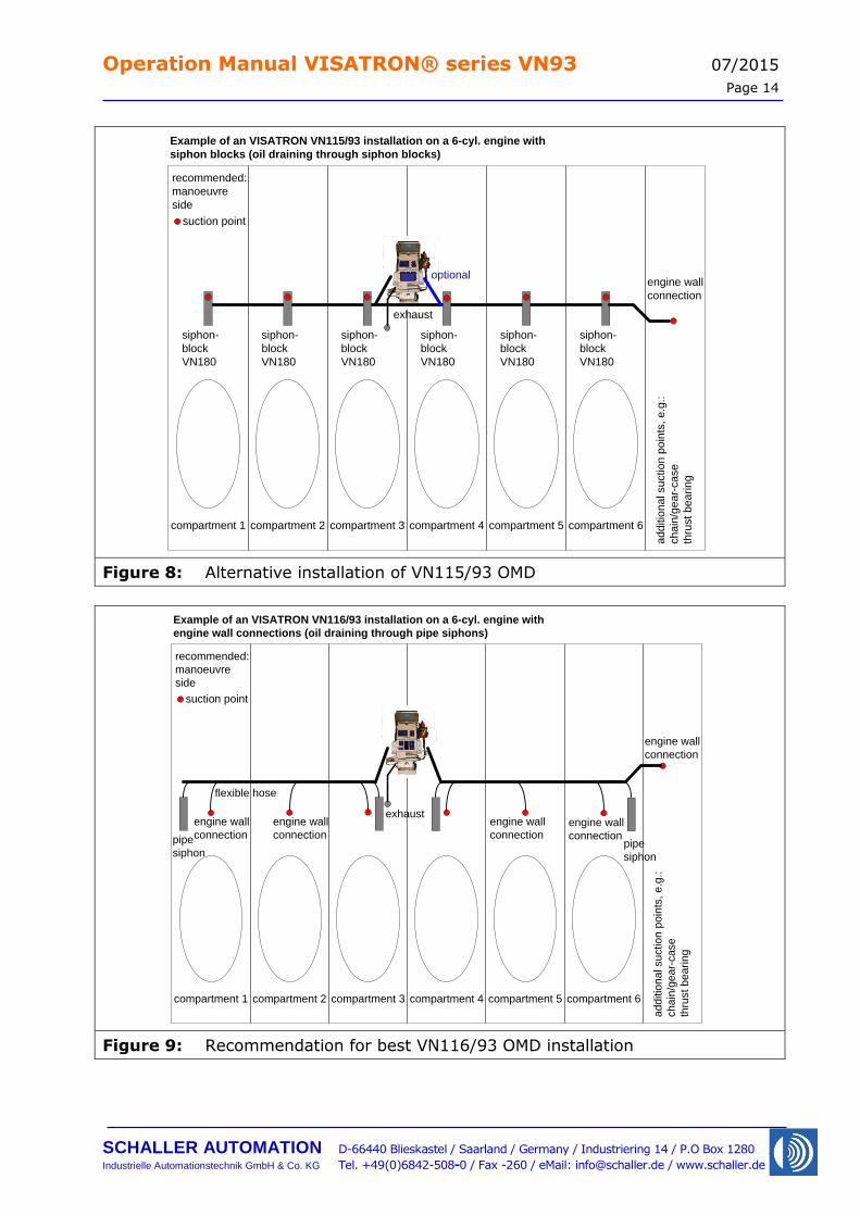
Example of an VISATRON VN115/93 installation on a 6-cyl. engine with
engine wall connections (oil draining through pipe siphons)
exhaust
suction point
engine wall
connection
engine wall
connectionpipe
siphon
engine wall
connection
engine wall
connection
engine wall
connection
engine wall
connection
engine wall
connectionpipe
siphon
flexible hose
Figure 7: Recommendation for best VN115/93 OMD installation
Operation Manual VISATRON® series VN93 07/2015
Page 14
SCHALLER AUTOMATION D-66440 Blieskastel / Saarland / Germany / Industriering 14 / P.O Box 1280
Industrielle Automationstechnik GmbH & Co. KG Tel. +49(0)6842-508-0 / Fax -260 / eMail: [email protected] / www.schaller.de
siphon-
block
VN180
compartment 1
ad
ditio
na
l su
ctio
n p
oin
ts, e.g
.:
ch
ain
/ge
ar-
ca
se
thru
st b
ea
rin
g
siphon-
block
VN180
siphon-
block
VN180
siphon-
block
VN180
siphon-
block
VN180
siphon-
block
VN180
compartment 2 compartment 3 compartment 4 compartment 5 compartment 6
recommended:
manoeuvre
side
Example of an VISATRON VN115/93 installation on a 6-cyl. engine with
siphon blocks (oil draining through siphon blocks)
exhaust
suction point
optionalengine wall
connection
Figure 8: Alternative installation of VN115/93 OMD
compartment 1
ad
ditio
na
l su
ctio
n p
oin
ts, e.g
.:
ch
ain
/ge
ar-
ca
se
thru
st b
ea
rin
g
compartment 2 compartment 3 compartment 4 compartment 5 compartment 6
recommended:
manoeuvre
side
Example of an VISATRON VN116/93 installation on a 6-cyl. engine with
engine wall connections (oil draining through pipe siphons)
exhaust
suction point
engine wall
connection
engine wall
connectionpipe
siphon
engine wall
connection
engine wall
connection
engine wall
connectionpipe
siphon
flexible hose
Figure 9: Recommendation for best VN116/93 OMD installation
Operation Manual VISATRON® series VN93 07/2015
Page 15
SCHALLER AUTOMATION D-66440 Blieskastel / Saarland / Germany / Industriering 14 / P.O Box 1280
Industrielle Automationstechnik GmbH & Co. KG Tel. +49(0)6842-508-0 / Fax -260 / eMail: [email protected] / www.schaller.de
siphon-
block
VN180
compartment 1
ad
ditio
na
l su
ctio
n p
oin
ts, e.g
.:
ch
ain
/ge
ar-
ca
se
thru
st b
ea
rin
g
siphon-
block
VN180
siphon-
block
VN180
siphon-
block
VN180
siphon-
block
VN180
siphon-
block
VN180
compartment 2 compartment 3 compartment 4 compartment 5 compartment 6
recommended:
manoeuvre
side
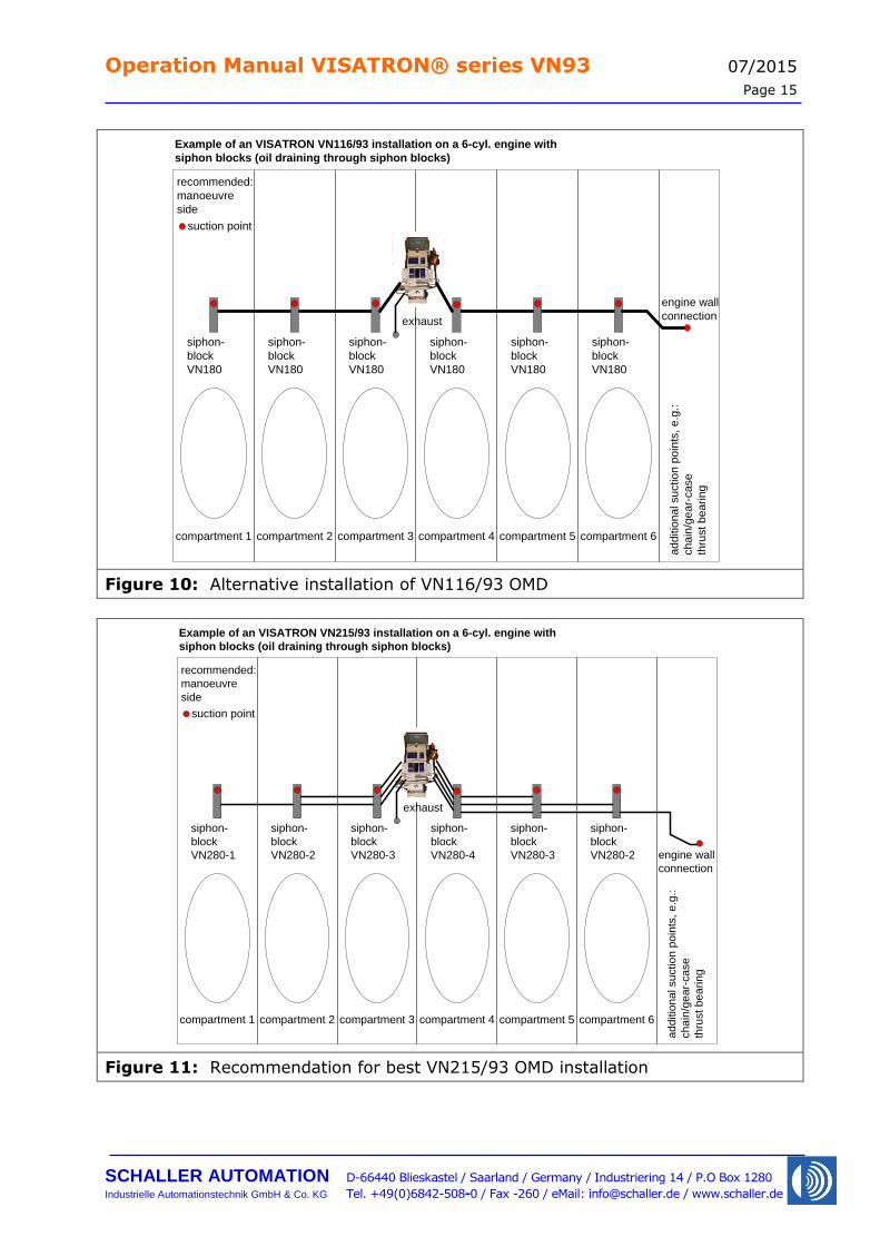
Example of an VISATRON VN116/93 installation on a 6-cyl. engine with
siphon blocks (oil draining through siphon blocks)
exhaust
suction point
engine wall
connection
Figure 10: Alternative installation of VN116/93 OMD
siphon-
block
VN280-1 engine wall
connection
compartment 1
ad
ditio
na
l su
ctio
n p
oin
ts, e.g
.:
ch
ain
/ge
ar-
ca
se
thru
st b
ea
rin
g
siphon-
block
VN280-2
siphon-
block
VN280-3
siphon-
block
VN280-4
siphon-
block
VN280-3
siphon-
block
VN280-2
compartment 2 compartment 3 compartment 4 compartment 5 compartment 6
recommended:
manoeuvre
side
Example of an VISATRON VN215/93 installation on a 6-cyl. engine with
siphon blocks (oil draining through siphon blocks)
exhaust
suction point
Figure 11: Recommendation for best VN215/93 OMD installation
Operation Manual VISATRON® series VN93 07/2015
Page 16
SCHALLER AUTOMATION D-66440 Blieskastel / Saarland / Germany / Industriering 14 / P.O Box 1280
Industrielle Automationstechnik GmbH & Co. KG Tel. +49(0)6842-508-0 / Fax -260 / eMail: [email protected] / www.schaller.de
engine wall
connection
compartment 1
ad
ditio
na
l su
ctio
n p
oin
ts, e.g
.:
ch
ain
/ge
ar-
ca
se
thru
st b
ea
rin
g
compartment 2 compartment 3 compartment 4 compartment 5 compartment 6
recommended:
manoeuvre
side
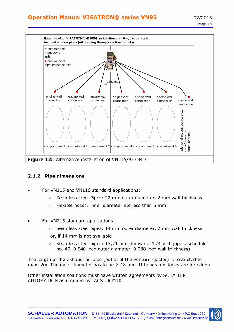
Example of an VISATRON VN215/93 installation on a 6-cyl. engine with
inclined suction pipes (oil draining through suction funnels)
exhaust
engine wall
connection
suction point
engine wall
connection
engine wall
connection
engine wall
connection
engine wall
connection
engine wall
connection
pipe inclination >6°
Figure 12: Alternative installation of VN215/93 OMD
2.1.2 Pipe dimensions
For VN115 and VN116 standard applications:
o Seamless steel Pipes: 22 mm outer diameter, 2 mm wall thickness
o Flexible hoses: inner diameter not less than 6 mm
For VN215 standard applications:
o Seamless steel pipes: 14 mm outer diameter, 2 mm wall thickness
or, if 14 mm is not available
o Seamless steel pipes: 13,71 mm (known as1 /4-inch pipes, schedule
no. 40, 0.540 inch outer diameter, 0.088 inch wall thickness)
The length of the exhaust air pipe (outlet of the venturi injector) is restricted to max. 2m. The inner diameter has to be ≥ 18 mm. U-bends and kinks are forbidden.
Other installation solutions must have written agreements by SCHALLER AUTOMATION as required by IACS UR M10.
Operation Manual VISATRON® series VN93 07/2015
Page 17
SCHALLER AUTOMATION D-66440 Blieskastel / Saarland / Germany / Industriering 14 / P.O Box 1280
Industrielle Automationstechnik GmbH & Co. KG Tel. +49(0)6842-508-0 / Fax -260 / eMail: [email protected] / www.schaller.de
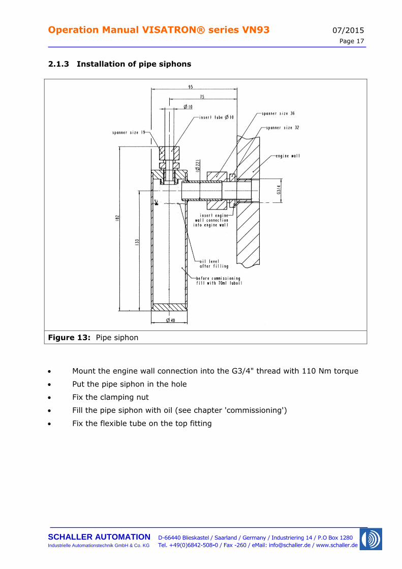
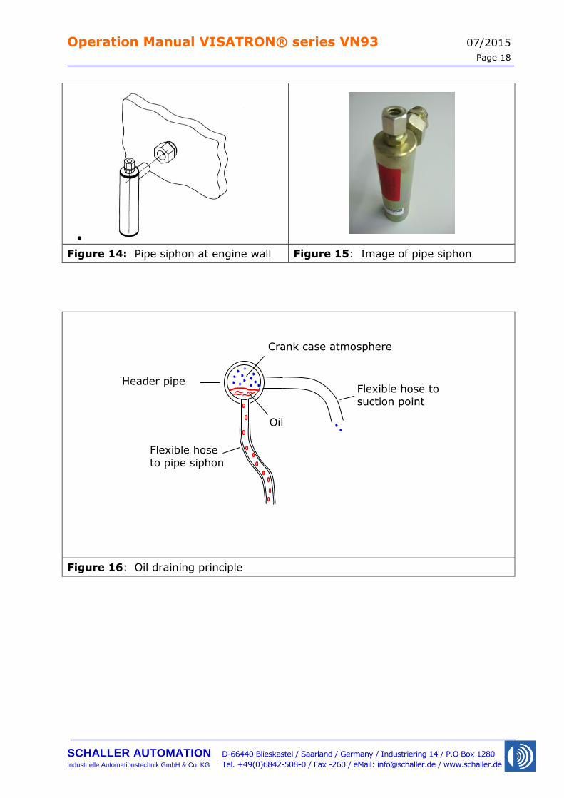
2.1.3 Installation of pipe siphons
Figure 13: Pipe siphon
Mount the engine wall connection into the G3/4" thread with 110 Nm torque
Put the pipe siphon in the hole
Fix the clamping nut
Fill the pipe siphon with oil (see chapter 'commissioning')
Fix the flexible tube on the top fitting
Operation Manual VISATRON® series VN93 07/2015
Page 18
SCHALLER AUTOMATION D-66440 Blieskastel / Saarland / Germany / Industriering 14 / P.O Box 1280
Industrielle Automationstechnik GmbH & Co. KG Tel. +49(0)6842-508-0 / Fax -260 / eMail: [email protected] / www.schaller.de
Figure 14: Pipe siphon at engine wall Figure 15: Image of pipe siphon
Figure 16: Oil draining principle
Header pipe Flexible hose to
suction point
Flexible hose
to pipe siphon
Crank case atmosphere
Oil

Operation Manual VISATRON® series VN93 07/2015
Page 19
SCHALLER AUTOMATION D-66440 Blieskastel / Saarland / Germany / Industriering 14 / P.O Box 1280
Industrielle Automationstechnik GmbH & Co. KG Tel. +49(0)6842-508-0 / Fax -260 / eMail: [email protected] / www.schaller.de
2.1.4 Installation of the siphon block connection units
Figure 17: Connection unit
Consider the following points:
Take note of the drilling template (made of paper, included with the connection units)
Drill through
Seal all threads with 'Loctite 572'
Max. torque = 30 Nm
OKAY Wrong alignment Wrong angles Wrong distance
Figure 18: Side view
Avoid wrong alignment, wrong angles and incorrect distances (see Figure 18)
Insert the suction funnel from the crankcase side into the siphon block, align it in a vertical position (see Figure 19) with the opening at the bottom
and fix the small clamping nut.
1
2
3
Operation Manual VISATRON® series VN93 07/2015
Page 20
SCHALLER AUTOMATION D-66440 Blieskastel / Saarland / Germany / Industriering 14 / P.O Box 1280
Industrielle Automationstechnik GmbH & Co. KG Tel. +49(0)6842-508-0 / Fax -260 / eMail: [email protected] / www.schaller.de
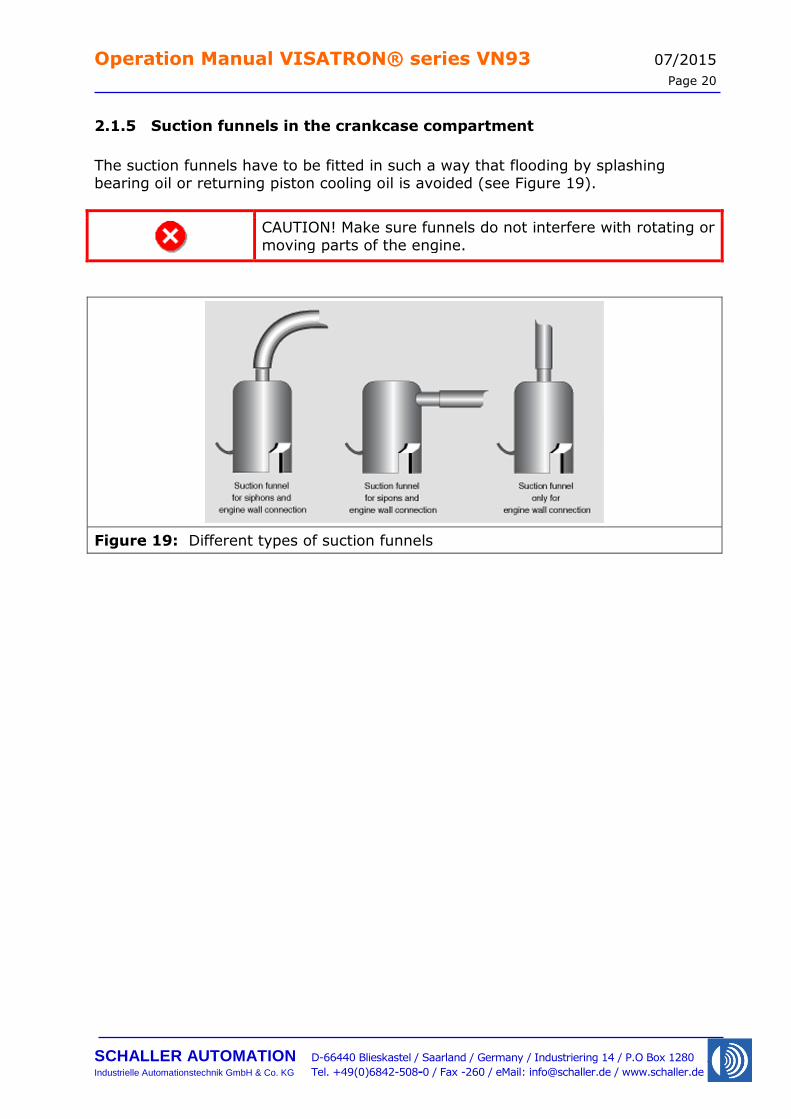
2.1.5 Suction funnels in the crankcase compartment
The suction funnels have to be fitted in such a way that flooding by splashing bearing oil or returning piston cooling oil is avoided (see Figure 19).
CAUTION! Make sure funnels do not interfere with rotating or
moving parts of the engine.
Figure 19: Different types of suction funnels
Operation Manual VISATRON® series VN93 07/2015
Page 21
SCHALLER AUTOMATION D-66440 Blieskastel / Saarland / Germany / Industriering 14 / P.O Box 1280
Industrielle Automationstechnik GmbH & Co. KG Tel. +49(0)6842-508-0 / Fax -260 / eMail: [email protected] / www.schaller.de
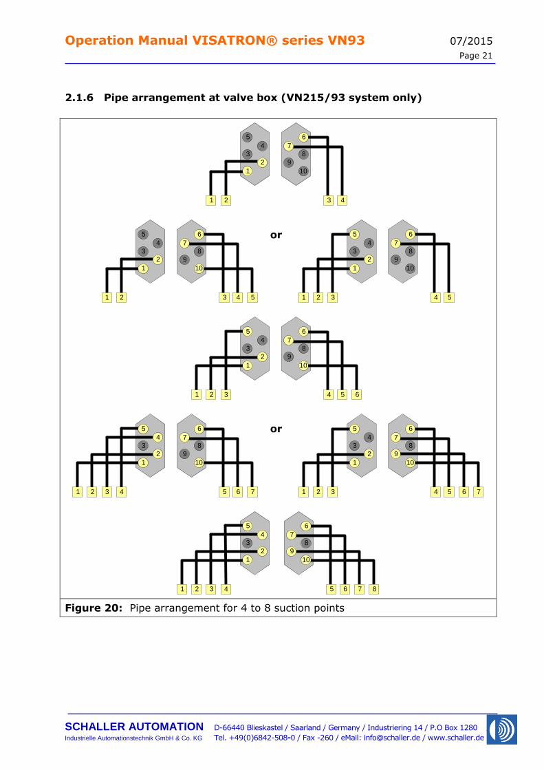
2.1.6 Pipe arrangement at valve box (VN215/93 system only)
5
3
1
4
2
6
8
7
9
10
21 4 5
5
3
1
4
2
6
8
7
9
10
32 4 5
5
3
1
4
2
6
8
7
9
10
43 5 6
5
3
1
4
2
6
8
7
9
10
21 3 4
5
3
1
4
2
6
8
7
9
10
21 3 4
5 3
61
71 2
5
3
1
4
2
6
8
7
9
10
32 4 5 61 7
6
8
7
9
10
5 6 7 8
5
3
1
4
2
431 2
Figure 20: Pipe arrangement for 4 to 8 suction points
or
or
Operation Manual VISATRON® series VN93 07/2015
Page 22
SCHALLER AUTOMATION D-66440 Blieskastel / Saarland / Germany / Industriering 14 / P.O Box 1280
Industrielle Automationstechnik GmbH & Co. KG Tel. +49(0)6842-508-0 / Fax -260 / eMail: [email protected] / www.schaller.de
6
8
7
9
10
6 7 8 9
5
3
1
4
2
541 2
5
3
1
4
2
431 2
6
8
7
9
10
5 6 7 8 9 3
5
3
1
4
2
541 2 3
6
8
7
9
10
6 7 8 9 10
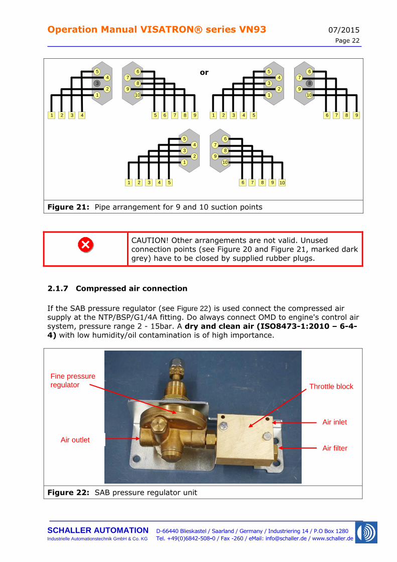
Figure 21: Pipe arrangement for 9 and 10 suction points
CAUTION! Other arrangements are not valid. Unused connection points (see Figure 20 and Figure 21, marked dark
grey) have to be closed by supplied rubber plugs.
2.1.7 Compressed air connection
If the SAB pressure regulator (see Figure 22) is used connect the compressed air supply at the NTP/BSP/G1/4A fitting. Do always connect OMD to engine's control air
system, pressure range 2 - 15bar. A dry and clean air (ISO8473-1:2010 – 6-4-4) with low humidity/oil contamination is of high importance.
Figure 22: SAB pressure regulator unit
or
Air inlet
Air outlet
Throttle block
Air filter
Fine pressure regulator
Operation Manual VISATRON® series VN93 07/2015
Page 23
SCHALLER AUTOMATION D-66440 Blieskastel / Saarland / Germany / Industriering 14 / P.O Box 1280
Industrielle Automationstechnik GmbH & Co. KG Tel. +49(0)6842-508-0 / Fax -260 / eMail: [email protected] / www.schaller.de
2.2 Electrical installation
2.2.1 VISATRON® series VN93 device
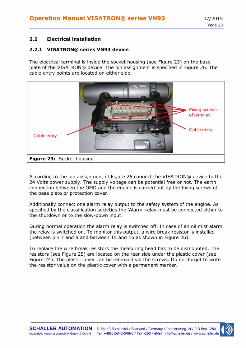
The electrical terminal is inside the socket housing (see Figure 23) on the base
plate of the VISATRON® device. The pin assignment is specified in Figure 26. The cable entry points are located on either side.
Figure 23: Socket housing
According to the pin assignment of Figure 26 connect the VISATRON® device to the 24 Volts power supply. The supply voltage can be potential free or not. The earth
connection between the OMD and the engine is carried out by the fixing screws of the base plate or protection cover.
Additionally connect one alarm relay output to the safety system of the engine. As specified by the classification societies the 'Alarm' relay must be connected either to
the shutdown or to the slow-down input. During normal operation the alarm relay is switched off. In case of an oil mist alarm
the relay is switched on. To monitor this output, a wire break resistor is installed (between pin 7 and 8 and between 15 and 16 as shown in Figure 26).
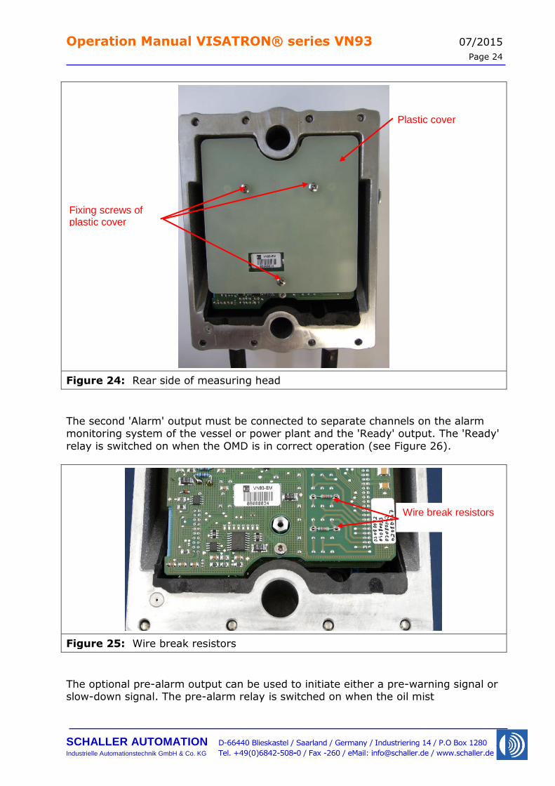
To replace the wire break resistors the measuring head has to be dismounted. The
resistors (see Figure 25) are located on the rear side under the plastic cover (see Figure 24). The plastic cover can be removed via the screws. Do not forget to write the resistor value on the plastic cover with a permanent marker.
Fixing screws of terminal
Cable entry
Cable entry
Operation Manual VISATRON® series VN93 07/2015
Page 24
SCHALLER AUTOMATION D-66440 Blieskastel / Saarland / Germany / Industriering 14 / P.O Box 1280
Industrielle Automationstechnik GmbH & Co. KG Tel. +49(0)6842-508-0 / Fax -260 / eMail: [email protected] / www.schaller.de
Figure 24: Rear side of measuring head
The second 'Alarm' output must be connected to separate channels on the alarm monitoring system of the vessel or power plant and the 'Ready' output. The 'Ready'
relay is switched on when the OMD is in correct operation (see Figure 26).
Figure 25: Wire break resistors
The optional pre-alarm output can be used to initiate either a pre-warning signal or slow-down signal. The pre-alarm relay is switched on when the oil mist
Fixing screws of plastic cover
Plastic cover
Wire break resistors
Operation Manual VISATRON® series VN93 07/2015
Page 25
SCHALLER AUTOMATION D-66440 Blieskastel / Saarland / Germany / Industriering 14 / P.O Box 1280
Industrielle Automationstechnik GmbH & Co. KG Tel. +49(0)6842-508-0 / Fax -260 / eMail: [email protected] / www.schaller.de
concentration has risen to the adjusted level. Depending on the characteristics of an oil mist occurrence the time between 'Pre-alarm' and 'Alarm' could be only a
fraction of a second.
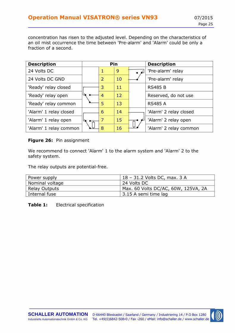
Description Pin Description
24 Volts DC 1 9 'Pre-alarm' relay
24 Volts DC GND 2 10 'Pre-alarm' relay
'Ready' relay closed 3 11 RS485 B
'Ready' relay open 4 12 Reserved, do not use
'Ready' relay common 5 13 RS485 A
'Alarm' 1 relay closed 6 14 'Alarm' 2 relay closed
'Alarm' 1 relay open 7 15 'Alarm' 2 relay open
'Alarm' 1 relay common 8 16 'Alarm' 2 relay common
Figure 26: Pin assignment
We recommend to connect 'Alarm' 1 to the alarm system and 'Alarm' 2 to the safety system.
The relay outputs are potential-free.
Power supply 18 – 31.2 Volts DC, max. 3 A
Nominal voltage 24 Volts DC
Relay Outputs Max. 60 Volts DC/AC, 60W, 125VA, 2A
Internal fuse 3.15 A semi time lag
Table 1: Electrical specification
Operation Manual VISATRON® series VN93 07/2015
Page 26
SCHALLER AUTOMATION D-66440 Blieskastel / Saarland / Germany / Industriering 14 / P.O Box 1280
Industrielle Automationstechnik GmbH & Co. KG Tel. +49(0)6842-508-0 / Fax -260 / eMail: [email protected] / www.schaller.de
2.2.2 Connection of monitoring devices
As required by IACS UR M10 the OMD device can be connected to Schaller's remote monitoring devices Remote Indicator II to monitor the oil mist concentration and
the OMD status from a safe location. The connection to the monitoring devices is accomplished via a RS485 two-wire
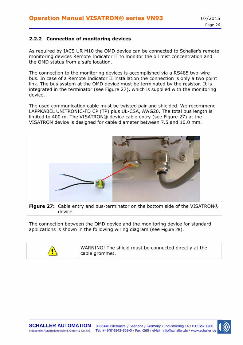
bus. In case of a Remote Indicator II installation the connection is only a two point link. The bus system at the OMD device must be terminated by the resistor. It is
integrated in the terminator (see Figure 27), which is supplied with the monitoring device.
The used communication cable must be twisted pair and shielded. We recommend LAPPKABEL UNITRONIC-FD CP (TP) plus UL-CSA, AWG20. The total bus length is
limited to 400 m. The VISATRON® device cable entry (see Figure 27) at the VISATRON device is designed for cable diameter between 7.5 and 10.0 mm.
Figure 27: Cable entry and bus-terminator on the bottom side of the VISATRON® device
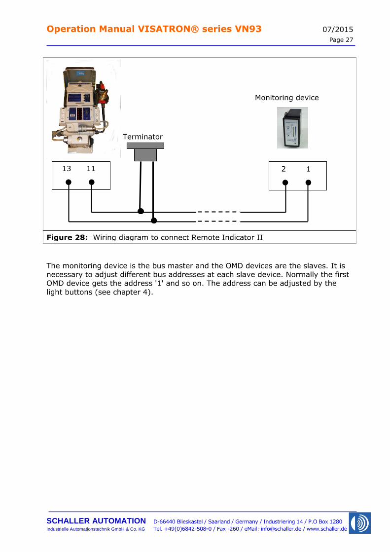
The connection between the OMD device and the monitoring device for standard applications is shown in the following wiring diagram (see Figure 28).
WARNING! The shield must be connected directly at the
cable grommet.
Operation Manual VISATRON® series VN93 07/2015
Page 27
SCHALLER AUTOMATION D-66440 Blieskastel / Saarland / Germany / Industriering 14 / P.O Box 1280
Industrielle Automationstechnik GmbH & Co. KG Tel. +49(0)6842-508-0 / Fax -260 / eMail: [email protected] / www.schaller.de
Figure 28: Wiring diagram to connect Remote Indicator II
The monitoring device is the bus master and the OMD devices are the slaves. It is necessary to adjust different bus addresses at each slave device. Normally the first OMD device gets the address '1' and so on. The address can be adjusted by the
light buttons (see chapter 4).
13 11
● ●
2 1
● ●
Terminator
Monitoring device
Operation Manual VISATRON® series VN93 07/2015
Page 28
SCHALLER AUTOMATION D-66440 Blieskastel / Saarland / Germany / Industriering 14 / P.O Box 1280
Industrielle Automationstechnik GmbH & Co. KG Tel. +49(0)6842-508-0 / Fax -260 / eMail: [email protected] / www.schaller.de
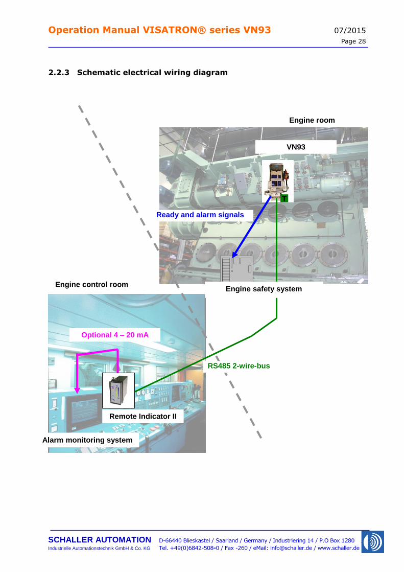
2.2.3 Schematic electrical wiring diagram
Engine room
T
Ready and alarm signals
RS485 2-wire-bus
Remote Indicator II
Alarm monitoring system
Engine safety system
VN93
Engine control room
Optional 4 – 20 mA link
Operation Manual VISATRON® series VN93 07/2015
Page 29
SCHALLER AUTOMATION D-66440 Blieskastel / Saarland / Germany / Industriering 14 / P.O Box 1280
Industrielle Automationstechnik GmbH & Co. KG Tel. +49(0)6842-508-0 / Fax -260 / eMail: [email protected] / www.schaller.de
3 Commissioning
CAUTION! Unplug the OMD during welding processes
on the engine.
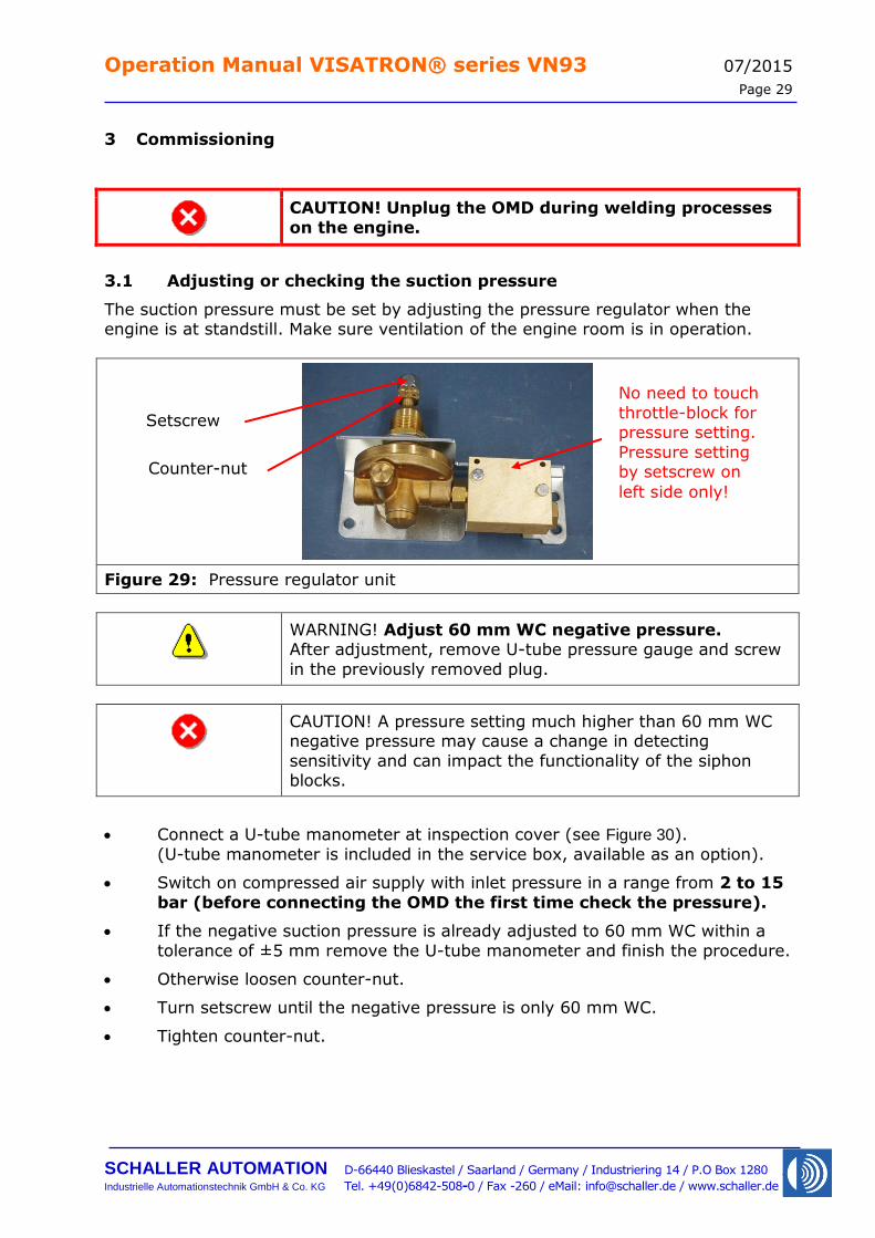
3.1 Adjusting or checking the suction pressure
The suction pressure must be set by adjusting the pressure regulator when the engine is at standstill. Make sure ventilation of the engine room is in operation.
Figure 29: Pressure regulator unit
WARNING! Adjust 60 mm WC negative pressure. After adjustment, remove U-tube pressure gauge and screw
in the previously removed plug.
CAUTION! A pressure setting much higher than 60 mm WC negative pressure may cause a change in detecting
sensitivity and can impact the functionality of the siphon blocks.
Connect a U-tube manometer at inspection cover (see Figure 30).
(U-tube manometer is included in the service box, available as an option).
Switch on compressed air supply with inlet pressure in a range from 2 to 15
bar (before connecting the OMD the first time check the pressure).
If the negative suction pressure is already adjusted to 60 mm WC within a
tolerance of ±5 mm remove the U-tube manometer and finish the procedure.
Otherwise loosen counter-nut.
Turn setscrew until the negative pressure is only 60 mm WC.
Tighten counter-nut.
Setscrew
Counter-nut
No need to touch
throttle-block for pressure setting.
Pressure setting by setscrew on
left side only!
Operation Manual VISATRON® series VN93 07/2015
Page 30
SCHALLER AUTOMATION D-66440 Blieskastel / Saarland / Germany / Industriering 14 / P.O Box 1280
Industrielle Automationstechnik GmbH & Co. KG Tel. +49(0)6842-508-0 / Fax -260 / eMail: [email protected] / www.schaller.de
Figure 30: U-tube manometer connected to OMD control cover
Remove U-tube manometer
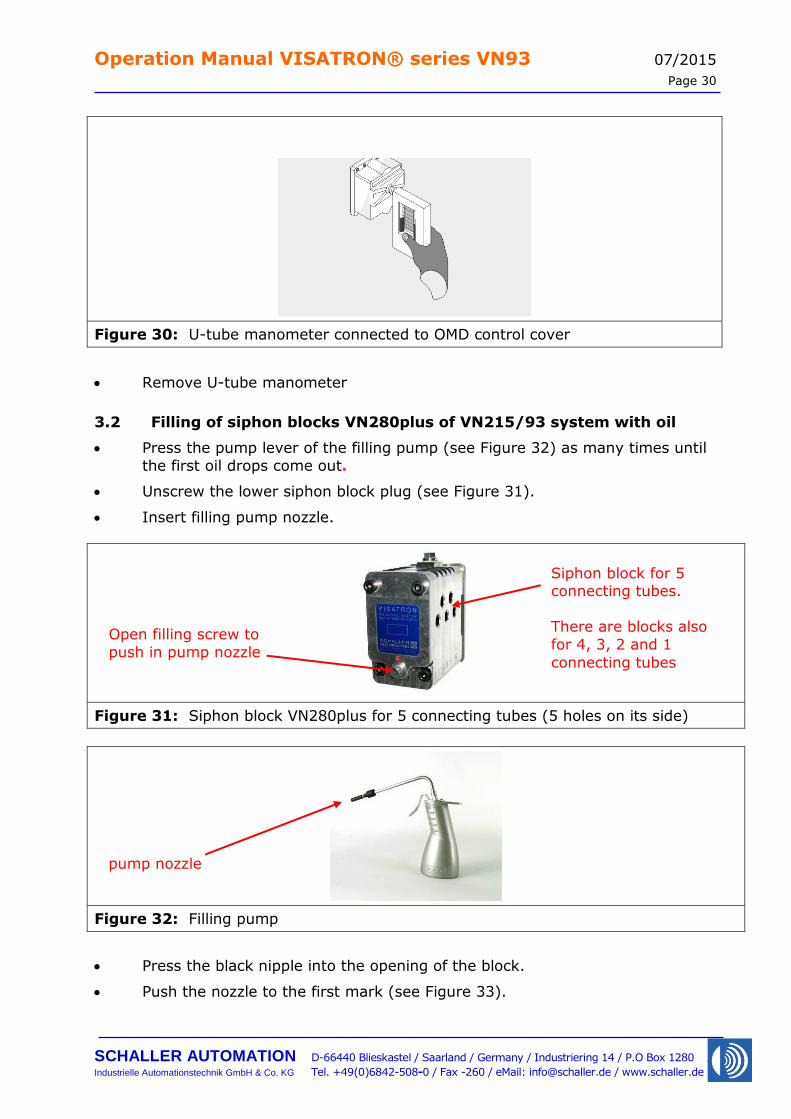
3.2 Filling of siphon blocks VN280plus of VN215/93 system with oil
Press the pump lever of the filling pump (see Figure 32) as many times until
the first oil drops come out.
Unscrew the lower siphon block plug (see Figure 31).
Insert filling pump nozzle.
Figure 31: Siphon block VN280plus for 5 connecting tubes (5 holes on its side)
Figure 32: Filling pump
Press the black nipple into the opening of the block.
Push the nozzle to the first mark (see Figure 33).
Open filling screw to
push in pump nozzle
Siphon block for 5 connecting tubes.
There are blocks also
for 4, 3, 2 and 1
connecting tubes
pump nozzle
Operation Manual VISATRON® series VN93 07/2015
Page 31
SCHALLER AUTOMATION D-66440 Blieskastel / Saarland / Germany / Industriering 14 / P.O Box 1280
Industrielle Automationstechnik GmbH & Co. KG Tel. +49(0)6842-508-0 / Fax -260 / eMail: [email protected] / www.schaller.de
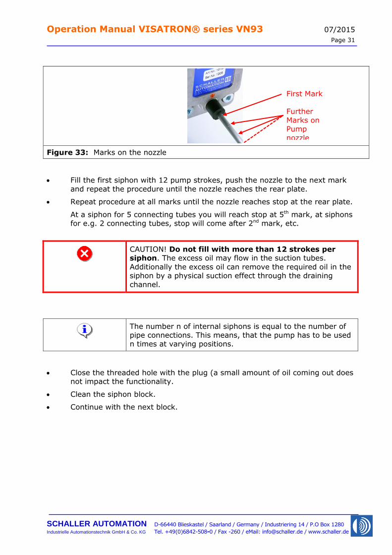
Figure 33: Marks on the nozzle
Fill the first siphon with 12 pump strokes, push the nozzle to the next mark
and repeat the procedure until the nozzle reaches the rear plate.
Repeat procedure at all marks until the nozzle reaches stop at the rear plate.
At a siphon for 5 connecting tubes you will reach stop at 5th mark, at siphons for e.g. 2 connecting tubes, stop will come after 2nd mark, etc.
CAUTION! Do not fill with more than 12 strokes per siphon. The excess oil may flow in the suction tubes.
Additionally the excess oil can remove the required oil in the siphon by a physical suction effect through the draining
channel.
The number n of internal siphons is equal to the number of pipe connections. This means, that the pump has to be used n times at varying positions.
Close the threaded hole with the plug (a small amount of oil coming out does not impact the functionality.
Clean the siphon block.
Continue with the next block.
First Mark
Further Marks on Pump
nozzle
Operation Manual VISATRON® series VN93 07/2015
Page 32
SCHALLER AUTOMATION D-66440 Blieskastel / Saarland / Germany / Industriering 14 / P.O Box 1280
Industrielle Automationstechnik GmbH & Co. KG Tel. +49(0)6842-508-0 / Fax -260 / eMail: [email protected] / www.schaller.de
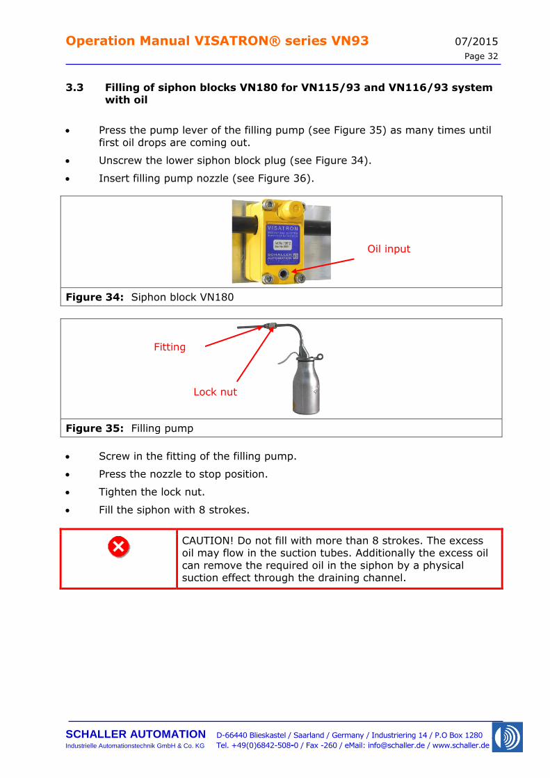
3.3 Filling of siphon blocks VN180 for VN115/93 and VN116/93 system with oil
Press the pump lever of the filling pump (see Figure 35) as many times until
first oil drops are coming out.
Unscrew the lower siphon block plug (see Figure 34).
Insert filling pump nozzle (see Figure 36).
Figure 34: Siphon block VN180
Figure 35: Filling pump
Screw in the fitting of the filling pump.
Press the nozzle to stop position.
Tighten the lock nut.
Fill the siphon with 8 strokes.
CAUTION! Do not fill with more than 8 strokes. The excess oil may flow in the suction tubes. Additionally the excess oil
can remove the required oil in the siphon by a physical suction effect through the draining channel.
Oil input
Fitting
Lock nut
Operation Manual VISATRON® series VN93 07/2015
Page 33
SCHALLER AUTOMATION D-66440 Blieskastel / Saarland / Germany / Industriering 14 / P.O Box 1280
Industrielle Automationstechnik GmbH & Co. KG Tel. +49(0)6842-508-0 / Fax -260 / eMail: [email protected] / www.schaller.de
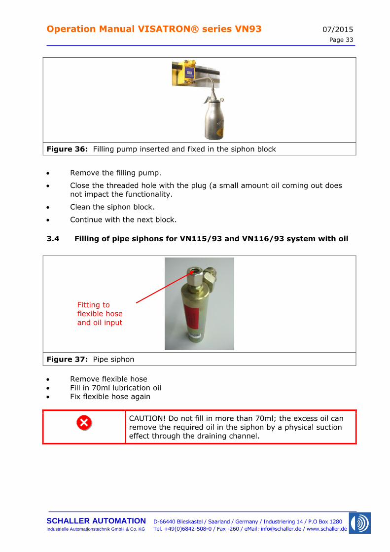
Figure 36: Filling pump inserted and fixed in the siphon block
Remove the filling pump.
Close the threaded hole with the plug (a small amount oil coming out does not impact the functionality.
Clean the siphon block.
Continue with the next block.
3.4 Filling of pipe siphons for VN115/93 and VN116/93 system with oil
Figure 37: Pipe siphon
Remove flexible hose
Fill in 70ml lubrication oil Fix flexible hose again
CAUTION! Do not fill in more than 70ml; the excess oil can
remove the required oil in the siphon by a physical suction effect through the draining channel.
Fitting to
flexible hose
and oil input
Operation Manual VISATRON® series VN93 07/2015
Page 34
SCHALLER AUTOMATION D-66440 Blieskastel / Saarland / Germany / Industriering 14 / P.O Box 1280
Industrielle Automationstechnik GmbH & Co. KG Tel. +49(0)6842-508-0 / Fax -260 / eMail: [email protected] / www.schaller.de
3.5 Adjusting the sensitivity of the OMD
The detector determines the oil mist concentration by an optical measurement. The
calculated values have the unit 'opacity'. 100% opacity means that no light is transmitted through the oil mist sample. This is equivalent to a complete white
wall. The IACS UR 67 requires an oil mist alarm at 5% of the Lower Explosion Level
(LEL). The LEL is equal to 47mg/l oil mist concentration in air at a temperature of 25 °C, which means that the OMD is required to indicate an oil mist alarm at
approx. 2.5mg/l.
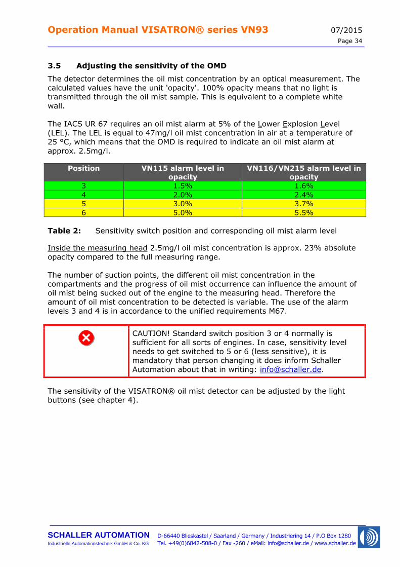
Position VN115 alarm level in
opacity
VN116/VN215 alarm level in
opacity
3 1.5% 1.6%
4 2.0% 2.4%
5 3.0% 3.7%
6 5.0% 5.5%
Table 2: Sensitivity switch position and corresponding oil mist alarm level
Inside the measuring head 2.5mg/l oil mist concentration is approx. 23% absolute
opacity compared to the full measuring range.
The number of suction points, the different oil mist concentration in the compartments and the progress of oil mist occurrence can influence the amount of oil mist being sucked out of the engine to the measuring head. Therefore the
amount of oil mist concentration to be detected is variable. The use of the alarm levels 3 and 4 is in accordance to the unified requirements M67.
CAUTION! Standard switch position 3 or 4 normally is
sufficient for all sorts of engines. In case, sensitivity level needs to get switched to 5 or 6 (less sensitive), it is mandatory that person changing it does inform Schaller
Automation about that in writing: [email protected].
The sensitivity of the VISATRON® oil mist detector can be adjusted by the light buttons (see chapter 4).
Operation Manual VISATRON® series VN93 07/2015
Page 35
SCHALLER AUTOMATION D-66440 Blieskastel / Saarland / Germany / Industriering 14 / P.O Box 1280
Industrielle Automationstechnik GmbH & Co. KG Tel. +49(0)6842-508-0 / Fax -260 / eMail: [email protected] / www.schaller.de
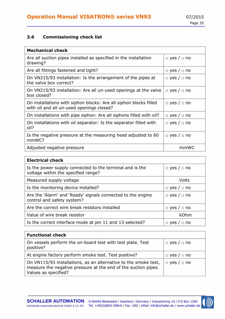
3.6 Commissioning check list
Mechanical check
Are all suction pipes installed as specified in the installation drawing?
□ yes / □ no
Are all fittings fastened and tight? □ yes / □ no
On VN215/93 installation: Is the arrangement of the pipes at
the valve box correct?
□ yes / □ no
On VN215/93 installation: Are all un-used openings at the valve box closed?
□ yes / □ no
On installations with siphon blocks: Are all siphon blocks filled
with oil and all un-used openings closed?
□ yes / □ no
On installations with pipe siphon: Are all siphons filled with oil? □ yes / □ no
On installations with oil separator: Is the separator filled with oil?
□ yes / □ no
Is the negative pressure at the measuring head adjusted to 60
mmWC?
□ yes / □ no
Adjusted negative pressure mmWC
Electrical check
Is the power supply connected to the terminal and is the
voltage within the specified range?
□ yes / □ no
Measured supply voltage Volts
Is the monitoring device installed? □ yes / □ no
Are the ‘Alarm’ and ‘Ready’ signals connected to the engine
control and safety system?
□ yes / □ no
Are the correct wire break resistors installed □ yes / □ no
Value of wire break resistor kOhm
Is the correct interface mode at pin 11 and 13 selected? □ yes / □ no
Functional check
On vessels perform the on-board test with test plate. Test
positive?
□ yes / □ no
At engine factory perform smoke test. Test positive? □ yes / □ no
On VN115/93 installations, as an alternative to the smoke test, measure the negative pressure at the end of the suction pipes.
Values as specified?
□ yes / □ no
Operation Manual VISATRON® series VN93 07/2015
Page 36
SCHALLER AUTOMATION D-66440 Blieskastel / Saarland / Germany / Industriering 14 / P.O Box 1280
Industrielle Automationstechnik GmbH & Co. KG Tel. +49(0)6842-508-0 / Fax -260 / eMail: [email protected] / www.schaller.de
4 Operating instructions
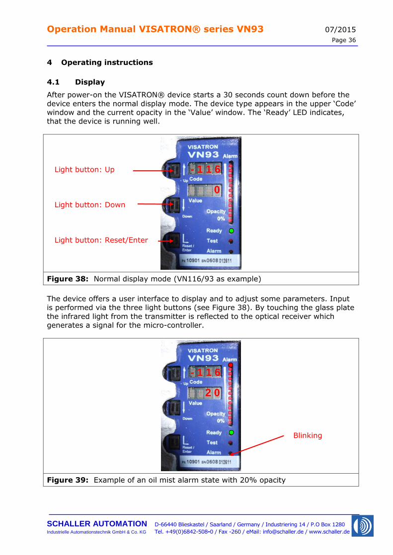
4.1 Display
After power-on the VISATRON® device starts a 30 seconds count down before the
device enters the normal display mode. The device type appears in the upper ‘Code’ window and the current opacity in the ‘Value’ window. The ‘Ready’ LED indicates, that the device is running well.
Figure 38: Normal display mode (VN116/93 as example)
The device offers a user interface to display and to adjust some parameters. Input is performed via the three light buttons (see Figure 38). By touching the glass plate
the infrared light from the transmitter is reflected to the optical receiver which generates a signal for the micro-controller.
Figure 39: Example of an oil mist alarm state with 20% opacity
Light button: Up
Light button: Down
Light button: Reset/Enter
- 1 1 6
0
Blinking
- 1 1 6
2 0
Operation Manual VISATRON® series VN93 07/2015
Page 37
SCHALLER AUTOMATION D-66440 Blieskastel / Saarland / Germany / Industriering 14 / P.O Box 1280
Industrielle Automationstechnik GmbH & Co. KG Tel. +49(0)6842-508-0 / Fax -260 / eMail: [email protected] / www.schaller.de
In case of a high oil mist concentration the LED bar goes up. At 100% opacity, compared to the alarm level, the 'Oil-Mist Alarm' LED starts blinking. If the opacity
later goes down, the alarm condition will be stored. The opacity is shown in the right LED bar. If the highest LED is switched on the opacity is equal or higher,
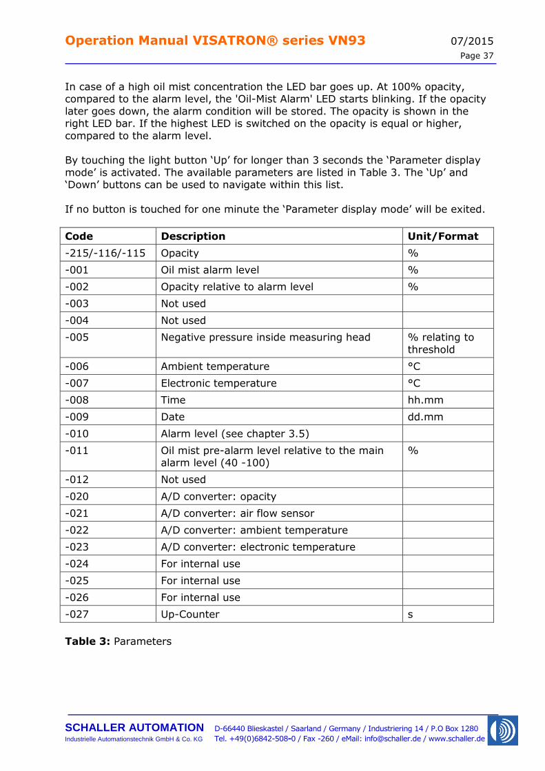
compared to the alarm level. By touching the light button ‘Up’ for longer than 3 seconds the ‘Parameter display
mode’ is activated. The available parameters are listed in Table 3. The ‘Up’ and ‘Down’ buttons can be used to navigate within this list.
If no button is touched for one minute the ‘Parameter display mode’ will be exited.
Code Description Unit/Format
-215/-116/-115 Opacity %
-001 Oil mist alarm level %
-002 Opacity relative to alarm level %
-003 Not used
-004 Not used
-005 Negative pressure inside measuring head % relating to
threshold
-006 Ambient temperature °C
-007 Electronic temperature °C
-008 Time hh.mm
-009 Date dd.mm
-010 Alarm level (see chapter 3.5)
-011 Oil mist pre-alarm level relative to the main alarm level (40 -100)
%
-012 Not used
-020 A/D converter: opacity
-021 A/D converter: air flow sensor
-022 A/D converter: ambient temperature
-023 A/D converter: electronic temperature
-024 For internal use
-025 For internal use
-026 For internal use
-027 Up-Counter s
Table 3: Parameters
Operation Manual VISATRON® series VN93 07/2015
Page 38
SCHALLER AUTOMATION D-66440 Blieskastel / Saarland / Germany / Industriering 14 / P.O Box 1280
Industrielle Automationstechnik GmbH & Co. KG Tel. +49(0)6842-508-0 / Fax -260 / eMail: [email protected] / www.schaller.de
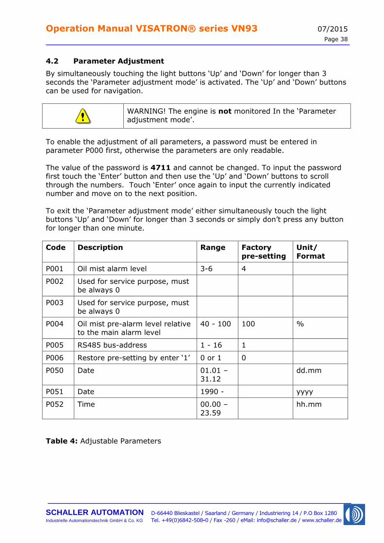
4.2 Parameter Adjustment
By simultaneously touching the light buttons ‘Up’ and ‘Down’ for longer than 3
seconds the ‘Parameter adjustment mode’ is activated. The ‘Up’ and ‘Down’ buttons can be used for navigation.
WARNING! The engine is not monitored In the ‘Parameter adjustment mode’.
To enable the adjustment of all parameters, a password must be entered in parameter P000 first, otherwise the parameters are only readable.
The value of the password is 4711 and cannot be changed. To input the password first touch the ‘Enter’ button and then use the ‘Up’ and ‘Down’ buttons to scroll
through the numbers. Touch ‘Enter’ once again to input the currently indicated number and move on to the next position.
To exit the ‘Parameter adjustment mode’ either simultaneously touch the light buttons ‘Up’ and ‘Down’ for longer than 3 seconds or simply don’t press any button
for longer than one minute.
Code Description Range Factory
pre-setting
Unit/
Format
P001 Oil mist alarm level 3-6 4
P002 Used for service purpose, must be always 0
P003 Used for service purpose, must be always 0
P004 Oil mist pre-alarm level relative to the main alarm level
40 - 100 100 %
P005 RS485 bus-address 1 - 16 1
P006 Restore pre-setting by enter ‘1’ 0 or 1 0
P050 Date 01.01 – 31.12
dd.mm
P051 Date 1990 - yyyy
P052 Time 00.00 –
23.59
hh.mm
Table 4: Adjustable Parameters
Operation Manual VISATRON® series VN93 07/2015
Page 39
SCHALLER AUTOMATION D-66440 Blieskastel / Saarland / Germany / Industriering 14 / P.O Box 1280
Industrielle Automationstechnik GmbH & Co. KG Tel. +49(0)6842-508-0 / Fax -260 / eMail: [email protected] / www.schaller.de
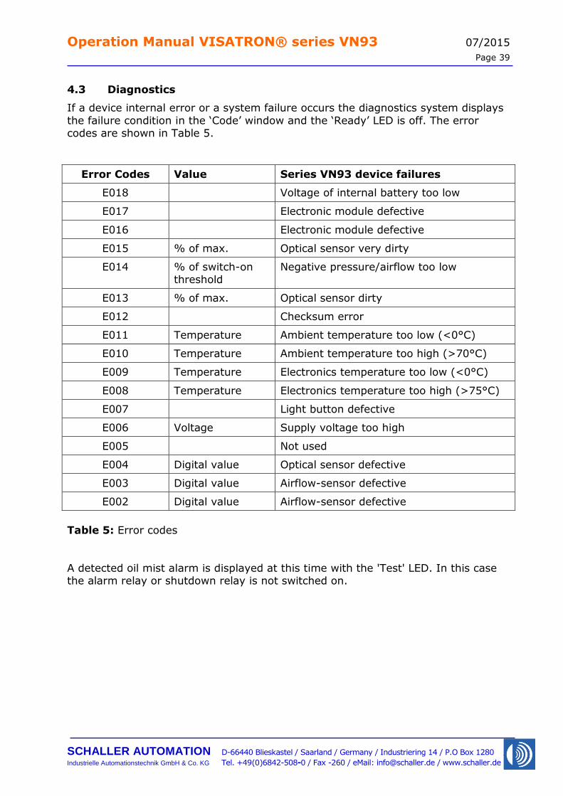
4.3 Diagnostics
If a device internal error or a system failure occurs the diagnostics system displays
the failure condition in the ‘Code’ window and the ‘Ready’ LED is off. The error codes are shown in Table 5.
Error Codes Value Series VN93 device failures
E018 Voltage of internal battery too low
E017 Electronic module defective
E016 Electronic module defective
E015 % of max. Optical sensor very dirty
E014 % of switch-on threshold
Negative pressure/airflow too low
E013 % of max. Optical sensor dirty
E012 Checksum error
E011 Temperature Ambient temperature too low (<0°C)
E010 Temperature Ambient temperature too high (>70°C)
E009 Temperature Electronics temperature too low (<0°C)
E008 Temperature Electronics temperature too high (>75°C)
E007 Light button defective
E006 Voltage Supply voltage too high
E005 Not used
E004 Digital value Optical sensor defective
E003 Digital value Airflow-sensor defective
E002 Digital value Airflow-sensor defective
Table 5: Error codes
A detected oil mist alarm is displayed at this time with the 'Test' LED. In this case the alarm relay or shutdown relay is not switched on.
Operation Manual VISATRON® series VN93 07/2015
Page 40
SCHALLER AUTOMATION D-66440 Blieskastel / Saarland / Germany / Industriering 14 / P.O Box 1280
Industrielle Automationstechnik GmbH & Co. KG Tel. +49(0)6842-508-0 / Fax -260 / eMail: [email protected] / www.schaller.de
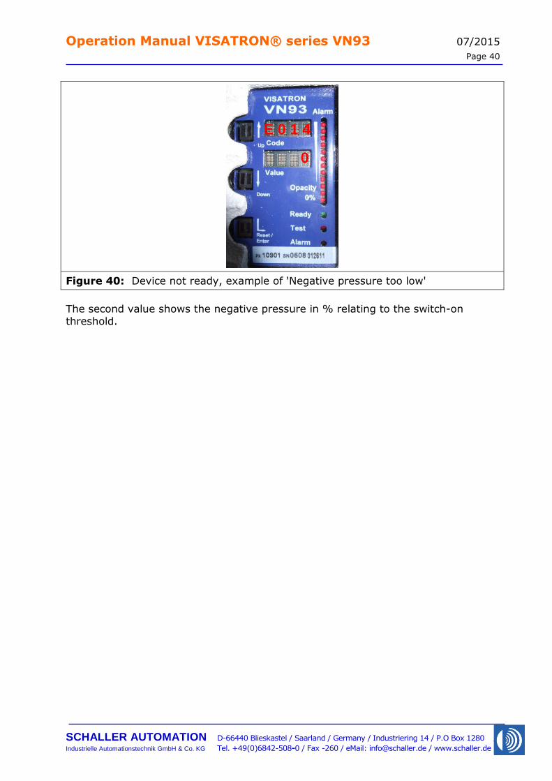
Figure 40: Device not ready, example of 'Negative pressure too low'
The second value shows the negative pressure in % relating to the switch-on threshold.
E 0 1 4
0
Operation Manual VISATRON® series VN93 07/2015
Page 41
SCHALLER AUTOMATION D-66440 Blieskastel / Saarland / Germany / Industriering 14 / P.O Box 1280
Industrielle Automationstechnik GmbH & Co. KG Tel. +49(0)6842-508-0 / Fax -260 / eMail: [email protected] / www.schaller.de
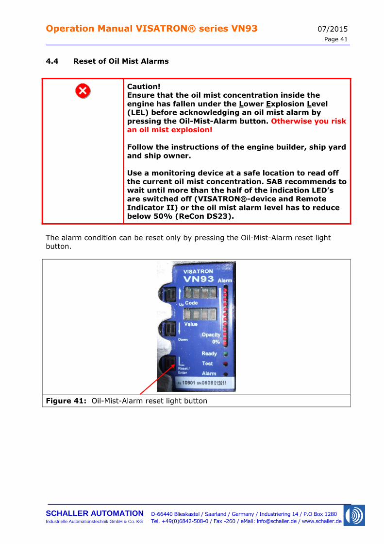
4.4 Reset of Oil Mist Alarms
Caution! Ensure that the oil mist concentration inside the
engine has fallen under the Lower Explosion Level (LEL) before acknowledging an oil mist alarm by
pressing the Oil-Mist-Alarm button. Otherwise you risk an oil mist explosion!
Follow the instructions of the engine builder, ship yard and ship owner.
Use a monitoring device at a safe location to read off the current oil mist concentration. SAB recommends to
wait until more than the half of the indication LED’s are switched off (VISATRON®-device and Remote
Indicator II) or the oil mist alarm level has to reduce below 50% (ReCon DS23).
The alarm condition can be reset only by pressing the Oil-Mist-Alarm reset light button.
Figure 41: Oil-Mist-Alarm reset light button
Operation Manual VISATRON® series VN93 07/2015
Page 42
SCHALLER AUTOMATION D-66440 Blieskastel / Saarland / Germany / Industriering 14 / P.O Box 1280
Industrielle Automationstechnik GmbH & Co. KG Tel. +49(0)6842-508-0 / Fax -260 / eMail: [email protected] / www.schaller.de
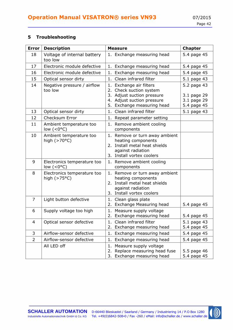
5 Troubleshooting
Error Description Measure Chapter
18 Voltage of internal battery
too low
1. Exchange measuring head 5.4 page 45
17 Electronic module defective 1. Exchange measuring head 5.4 page 45
16 Electronic module defective 1. Exchange measuring head 5.4 page 45
15 Optical sensor dirty 1. Clean infrared filter 5.1 page 43
14 Negative pressure / airflow
too low
1. Exchange air filters
2. Check suction system 3. Adjust suction pressure 4. Adjust suction pressure
5. Exchange measuring head
5.2 page 43
3.1 page 29 3.1 page 29
5.4 page 45
13 Optical sensor dirty 1. Clean infrared filter 5.1 page 43
12 Checksum Error 1. Repeat parameter setting
11 Ambient temperature too low (<0°C)
1. Remove ambient cooling components
10 Ambient temperature too
high (>70°C)
1. Remove or turn away ambient
heating components 2. Install metal heat shields
against radiation
3. Install vortex coolers
9 Electronics temperature too low (<0°C)
1. Remove ambient cooling components
8 Electronics temperature too high (>75°C)
1. Remove or turn away ambient heating components
2. Install metal heat shields
against radiation 3. Install vortex coolers
7 Light button defective 1. Clean glass plate 2. Exchange Measuring head
5.4 page 45
6 Supply voltage too high 1. Measure supply voltage 2. Exchange measuring head
5.4 page 45
4 Optical sensor defective 1. Clean infrared filter
2. Exchange measuring head
5.1 page 43
5.4 page 45
3 Airflow-sensor defective 1. Exchange measuring head 5.4 page 45
2 Airflow-sensor defective 1. Exchange measuring head 5.4 page 45
All LED off 1. Measure supply voltage 2. Replace measuring head fuse
3. Exchange measuring head
5.5 page 46
5.4 page 45
Operation Manual VISATRON® series VN93 07/2015
Page 43
SCHALLER AUTOMATION D-66440 Blieskastel / Saarland / Germany / Industriering 14 / P.O Box 1280
Industrielle Automationstechnik GmbH & Co. KG Tel. +49(0)6842-508-0 / Fax -260 / eMail: [email protected] / www.schaller.de
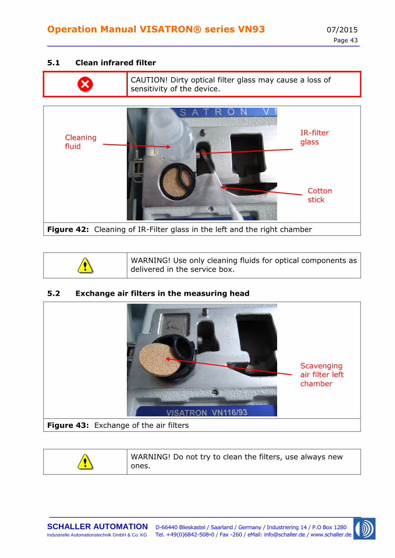
5.1 Clean infrared filter
CAUTION! Dirty optical filter glass may cause a loss of sensitivity of the device.
Figure 42: Cleaning of IR-Filter glass in the left and the right chamber
WARNING! Use only cleaning fluids for optical components as delivered in the service box.
5.2 Exchange air filters in the measuring head
Figure 43: Exchange of the air filters
WARNING! Do not try to clean the filters, use always new
ones.
IR-filter
glass Cleaning fluid
Cotton stick
Scavenging air filter left
chamber
Operation Manual VISATRON® series VN93 07/2015
Page 44
SCHALLER AUTOMATION D-66440 Blieskastel / Saarland / Germany / Industriering 14 / P.O Box 1280
Industrielle Automationstechnik GmbH & Co. KG Tel. +49(0)6842-508-0 / Fax -260 / eMail: [email protected] / www.schaller.de
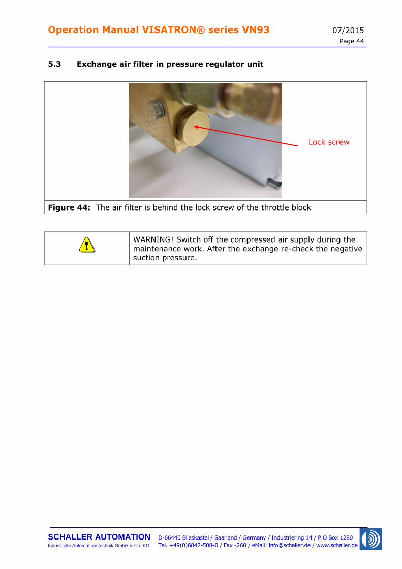
5.3 Exchange air filter in pressure regulator unit
Figure 44: The air filter is behind the lock screw of the throttle block
WARNING! Switch off the compressed air supply during the
maintenance work. After the exchange re-check the negative suction pressure.
Lock screw
Operation Manual VISATRON® series VN93 07/2015
Page 45
SCHALLER AUTOMATION D-66440 Blieskastel / Saarland / Germany / Industriering 14 / P.O Box 1280
Industrielle Automationstechnik GmbH & Co. KG Tel. +49(0)6842-508-0 / Fax -260 / eMail: [email protected] / www.schaller.de
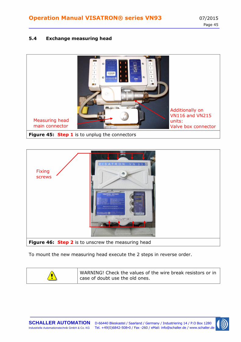
5.4 Exchange measuring head
Figure 45: Step 1 is to unplug the connectors
Figure 46: Step 2 is to unscrew the measuring head
To mount the new measuring head execute the 2 steps in reverse order.
WARNING! Check the values of the wire break resistors or in case of doubt use the old ones.
Fixing
screws
Measuring head
main connector
Additionally on
VN116 and VN215 units:
Valve box connector
Operation Manual VISATRON® series VN93 07/2015
Page 46
SCHALLER AUTOMATION D-66440 Blieskastel / Saarland / Germany / Industriering 14 / P.O Box 1280
Industrielle Automationstechnik GmbH & Co. KG Tel. +49(0)6842-508-0 / Fax -260 / eMail: [email protected] / www.schaller.de
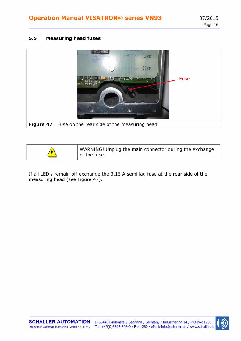
5.5 Measuring head fuses
Figure 47 Fuse on the rear side of the measuring head
WARNING! Unplug the main connector during the exchange of the fuse.
If all LED’s remain off exchange the 3.15 A semi lag fuse at the rear side of the
measuring head (see Figure 47).
Fuse
Operation Manual VISATRON® series VN93 07/2015
Page 47
SCHALLER AUTOMATION D-66440 Blieskastel / Saarland / Germany / Industriering 14 / P.O Box 1280
Industrielle Automationstechnik GmbH & Co. KG Tel. +49(0)6842-508-0 / Fax -260 / eMail: [email protected] / www.schaller.de
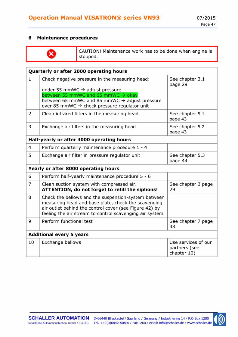
6 Maintenance procedures
CAUTION! Maintenance work has to be done when engine is stopped.
Quarterly or after 2000 operating hours
1 Check negative pressure in the measuring head:
under 55 mmWC adjust pressure between 55 mmWC and 65 mmWC okay
between 65 mmWC and 85 mmWC adjust pressure over 85 mmWC check pressure regulator unit
See chapter 3.1 page 29
2 Clean infrared filters in the measuring head See chapter 5.1
page 43
3 Exchange air filters in the measuring head See chapter 5.2
page 43
Half-yearly or after 4000 operating hours
4 Perform quarterly maintenance procedure 1 - 4
5 Exchange air filter in pressure regulator unit See chapter 5.3
page 44
Yearly or after 8000 operating hours
6 Perform half-yearly maintenance procedure 5 - 6
7 Clean suction system with compressed air. ATTENTION, do not forget to refill the siphons!
See chapter 3 page 29
8 Check the bellows and the suspension-system between
measuring head and base plate, check the scavenging air outlet behind the control cover (see Figure 42) by
feeling the air stream to control scavenging air system
9 Perform functional test See chapter 7 page 48
Additional every 5 years
10 Exchange bellows Use services of our
partners (see chapter 10)
Operation Manual VISATRON® series VN93 07/2015
Page 48
SCHALLER AUTOMATION D-66440 Blieskastel / Saarland / Germany / Industriering 14 / P.O Box 1280
Industrielle Automationstechnik GmbH & Co. KG Tel. +49(0)6842-508-0 / Fax -260 / eMail: [email protected] / www.schaller.de
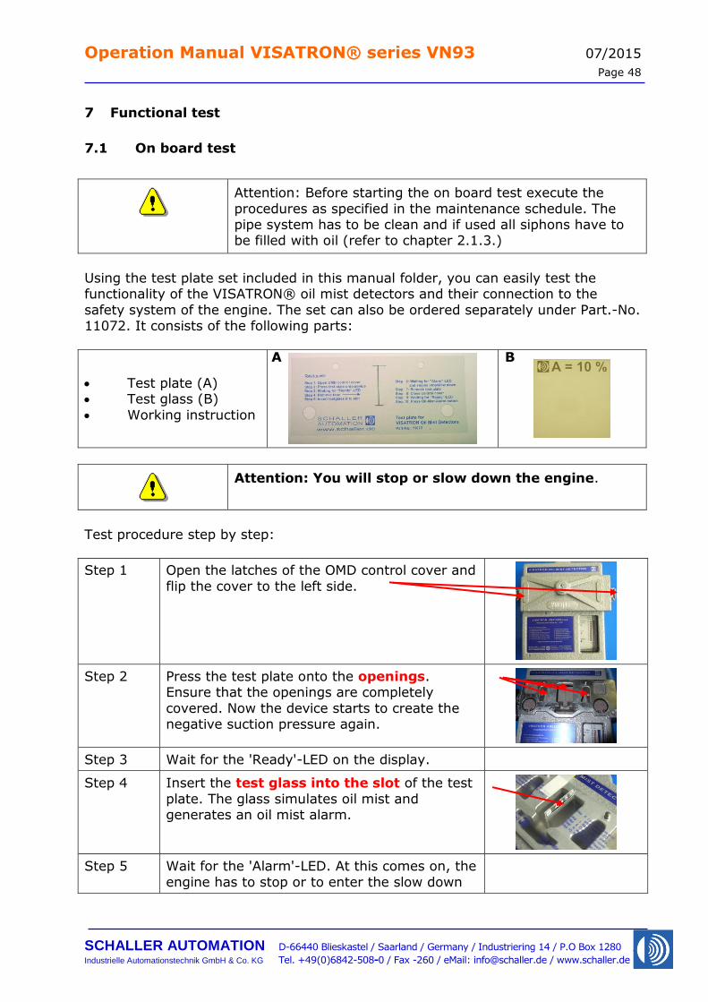
7 Functional test
7.1 On board test
Attention: Before starting the on board test execute the
procedures as specified in the maintenance schedule. The pipe system has to be clean and if used all siphons have to be filled with oil (refer to chapter 2.1.3.)
Using the test plate set included in this manual folder, you can easily test the functionality of the VISATRON® oil mist detectors and their connection to the
safety system of the engine. The set can also be ordered separately under Part.-No. 11072. It consists of the following parts:
Test plate (A) Test glass (B)
Working instruction
Attention: You will stop or slow down the engine.
Test procedure step by step:
Step 1 Open the latches of the OMD control cover and
flip the cover to the left side.
Step 2 Press the test plate onto the openings. Ensure that the openings are completely
covered. Now the device starts to create the negative suction pressure again.
Step 3 Wait for the 'Ready'-LED on the display.
Step 4 Insert the test glass into the slot of the test
plate. The glass simulates oil mist and generates an oil mist alarm.
Step 5 Wait for the 'Alarm'-LED. At this comes on, the
engine has to stop or to enter the slow down
A B
Operation Manual VISATRON® series VN93 07/2015
Page 49
SCHALLER AUTOMATION D-66440 Blieskastel / Saarland / Germany / Industriering 14 / P.O Box 1280
Industrielle Automationstechnik GmbH & Co. KG Tel. +49(0)6842-508-0 / Fax -260 / eMail: [email protected] / www.schaller.de
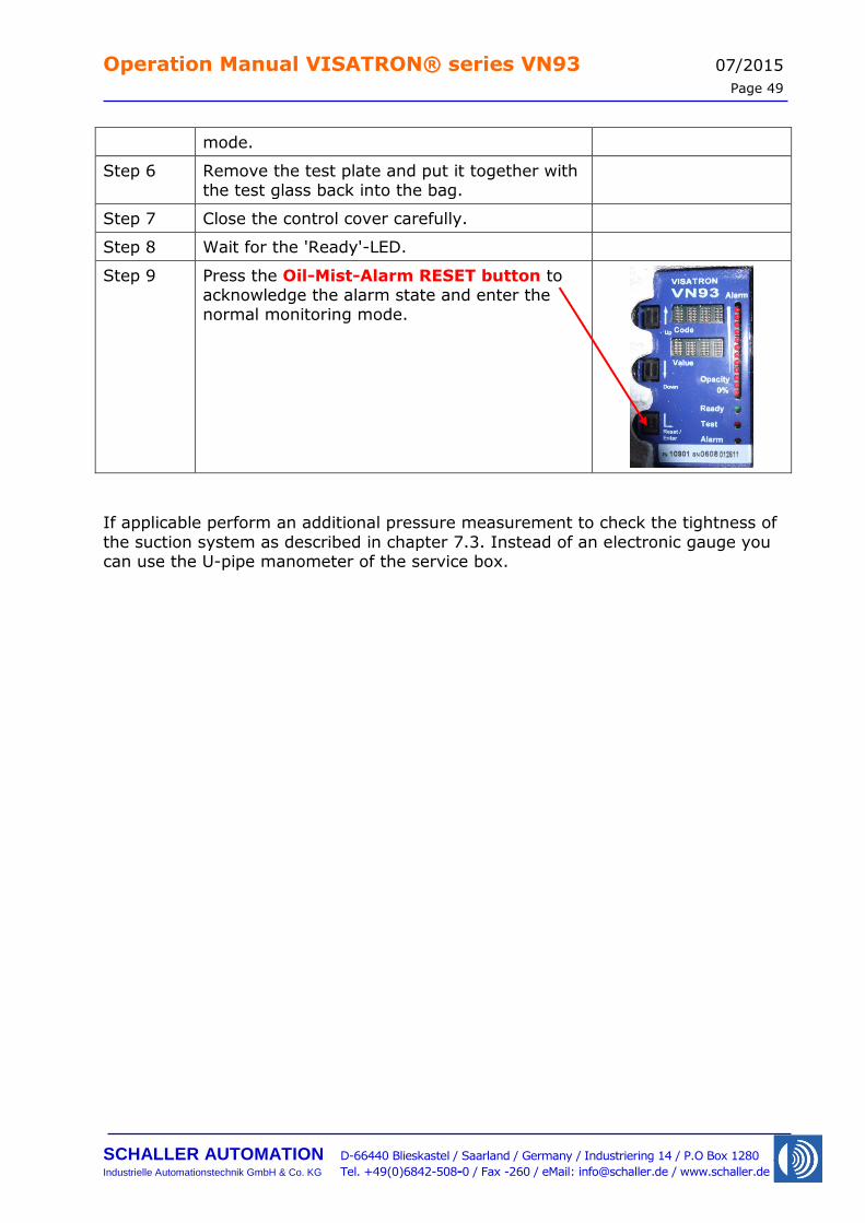
mode.
Step 6 Remove the test plate and put it together with the test glass back into the bag.
Step 7 Close the control cover carefully.
Step 8 Wait for the 'Ready'-LED.
Step 9 Press the Oil-Mist-Alarm RESET button to acknowledge the alarm state and enter the normal monitoring mode.
If applicable perform an additional pressure measurement to check the tightness of
the suction system as described in chapter 7.3. Instead of an electronic gauge you can use the U-pipe manometer of the service box.
Operation Manual VISATRON® series VN93 07/2015
Page 50
SCHALLER AUTOMATION D-66440 Blieskastel / Saarland / Germany / Industriering 14 / P.O Box 1280
Industrielle Automationstechnik GmbH & Co. KG Tel. +49(0)6842-508-0 / Fax -260 / eMail: [email protected] / www.schaller.de
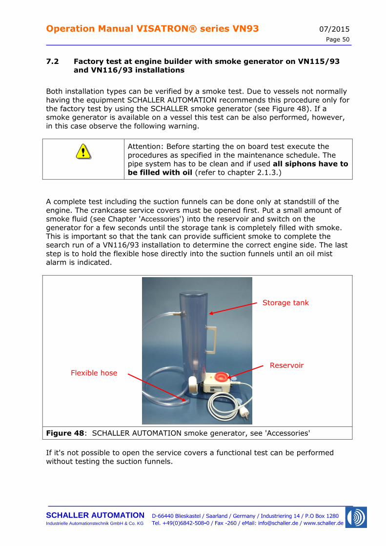
7.2 Factory test at engine builder with smoke generator on VN115/93 and VN116/93 installations
Both installation types can be verified by a smoke test. Due to vessels not normally
having the equipment SCHALLER AUTOMATION recommends this procedure only for the factory test by using the SCHALLER smoke generator (see Figure 48). If a smoke generator is available on a vessel this test can be also performed, however,
in this case observe the following warning.
Attention: Before starting the on board test execute the
procedures as specified in the maintenance schedule. The pipe system has to be clean and if used all siphons have to be filled with oil (refer to chapter 2.1.3.)
A complete test including the suction funnels can be done only at standstill of the
engine. The crankcase service covers must be opened first. Put a small amount of smoke fluid (see Chapter 'Accessories') into the reservoir and switch on the
generator for a few seconds until the storage tank is completely filled with smoke. This is important so that the tank can provide sufficient smoke to complete the search run of a VN116/93 installation to determine the correct engine side. The last
step is to hold the flexible hose directly into the suction funnels until an oil mist alarm is indicated.
Figure 48: SCHALLER AUTOMATION smoke generator, see 'Accessories'
If it's not possible to open the service covers a functional test can be performed
without testing the suction funnels.
Storage tank
Reservoir Flexible hose
Operation Manual VISATRON® series VN93 07/2015
Page 51
SCHALLER AUTOMATION D-66440 Blieskastel / Saarland / Germany / Industriering 14 / P.O Box 1280
Industrielle Automationstechnik GmbH & Co. KG Tel. +49(0)6842-508-0 / Fax -260 / eMail: [email protected] / www.schaller.de
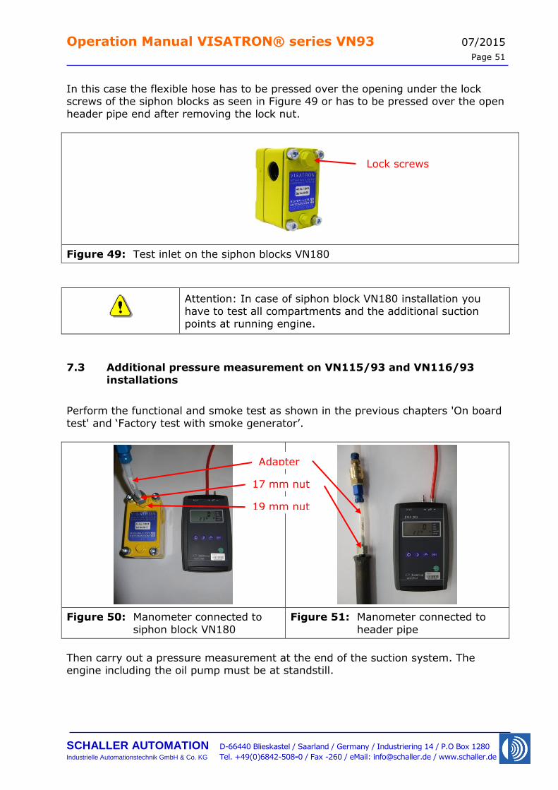
In this case the flexible hose has to be pressed over the opening under the lock screws of the siphon blocks as seen in Figure 49 or has to be pressed over the open
header pipe end after removing the lock nut.
Figure 49: Test inlet on the siphon blocks VN180
Attention: In case of siphon block VN180 installation you have to test all compartments and the additional suction points at running engine.
7.3 Additional pressure measurement on VN115/93 and VN116/93
installations
Perform the functional and smoke test as shown in the previous chapters 'On board
test' and ‘Factory test with smoke generator’.
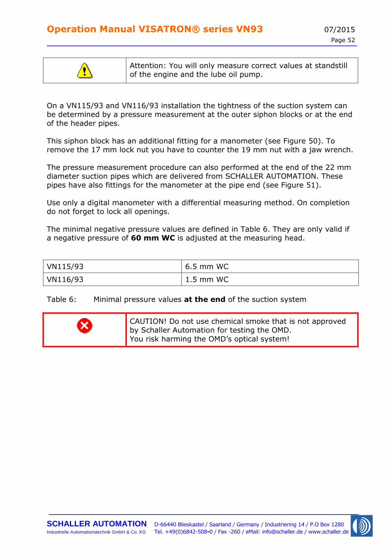
Figure 50: Manometer connected to
siphon block VN180
Figure 51: Manometer connected to
header pipe
Then carry out a pressure measurement at the end of the suction system. The engine including the oil pump must be at standstill.
19 mm nut
17 mm nut
Adapter
Lock screws
Operation Manual VISATRON® series VN93 07/2015
Page 52
SCHALLER AUTOMATION D-66440 Blieskastel / Saarland / Germany / Industriering 14 / P.O Box 1280
Industrielle Automationstechnik GmbH & Co. KG Tel. +49(0)6842-508-0 / Fax -260 / eMail: [email protected] / www.schaller.de
Attention: You will only measure correct values at standstill of the engine and the lube oil pump.
On a VN115/93 and VN116/93 installation the tightness of the suction system can be determined by a pressure measurement at the outer siphon blocks or at the end
of the header pipes.
This siphon block has an additional fitting for a manometer (see Figure 50). To remove the 17 mm lock nut you have to counter the 19 mm nut with a jaw wrench.
The pressure measurement procedure can also performed at the end of the 22 mm diameter suction pipes which are delivered from SCHALLER AUTOMATION. These
pipes have also fittings for the manometer at the pipe end (see Figure 51).
Use only a digital manometer with a differential measuring method. On completion do not forget to lock all openings.
The minimal negative pressure values are defined in Table 6. They are only valid if a negative pressure of 60 mm WC is adjusted at the measuring head.
VN115/93 6.5 mm WC
VN116/93 1.5 mm WC
Table 6: Minimal pressure values at the end of the suction system
CAUTION! Do not use chemical smoke that is not approved by Schaller Automation for testing the OMD.
You risk harming the OMD’s optical system!
Operation Manual VISATRON® series VN93 07/2015
Page 53
SCHALLER AUTOMATION D-66440 Blieskastel / Saarland / Germany / Industriering 14 / P.O Box 1280
Industrielle Automationstechnik GmbH & Co. KG Tel. +49(0)6842-508-0 / Fax -260 / eMail: [email protected] / www.schaller.de
7.4 Factory test at engine builder with fog machine on VN215/93 installations
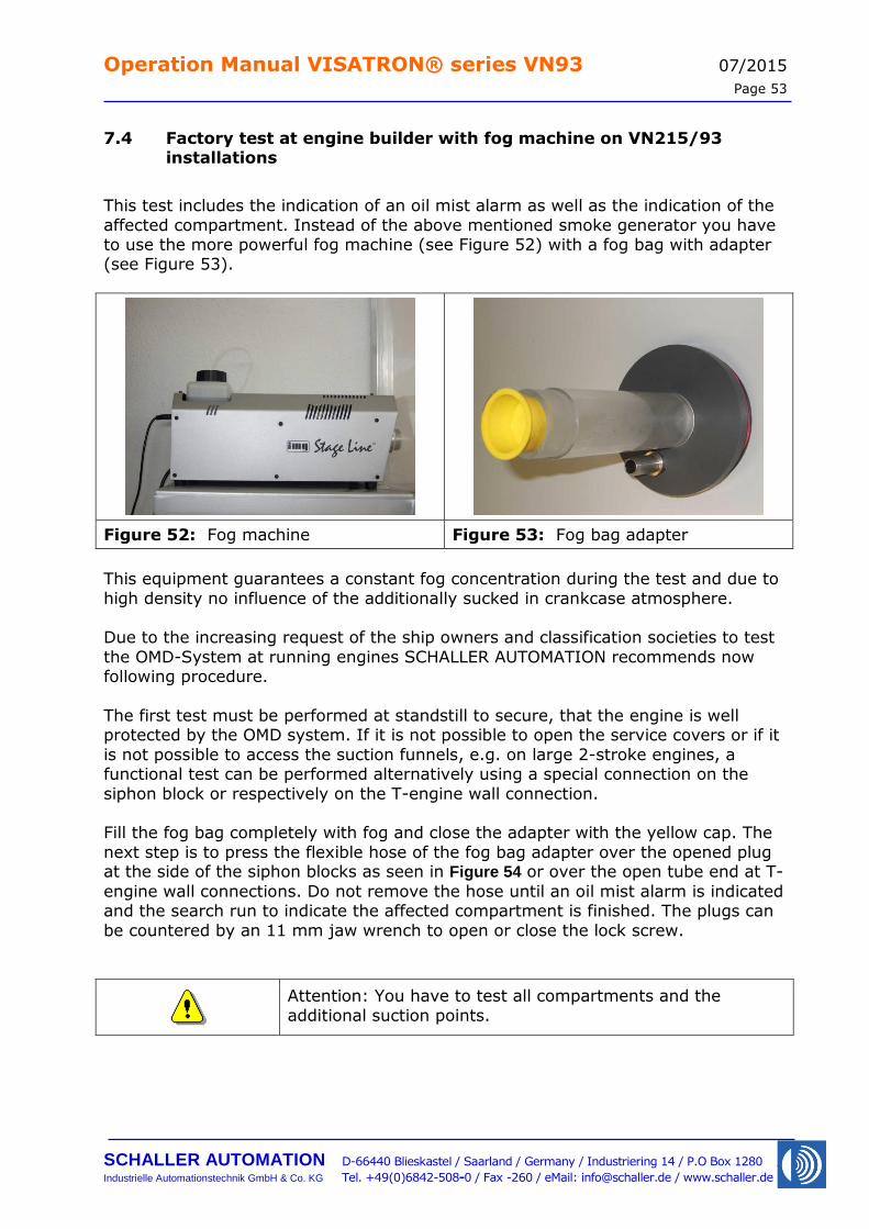
This test includes the indication of an oil mist alarm as well as the indication of the
affected compartment. Instead of the above mentioned smoke generator you have to use the more powerful fog machine (see Figure 52) with a fog bag with adapter (see Figure 53).
Figure 52: Fog machine Figure 53: Fog bag adapter
This equipment guarantees a constant fog concentration during the test and due to
high density no influence of the additionally sucked in crankcase atmosphere. Due to the increasing request of the ship owners and classification societies to test
the OMD-System at running engines SCHALLER AUTOMATION recommends now following procedure.
The first test must be performed at standstill to secure, that the engine is well protected by the OMD system. If it is not possible to open the service covers or if it
is not possible to access the suction funnels, e.g. on large 2-stroke engines, a functional test can be performed alternatively using a special connection on the
siphon block or respectively on the T-engine wall connection. Fill the fog bag completely with fog and close the adapter with the yellow cap. The
next step is to press the flexible hose of the fog bag adapter over the opened plug at the side of the siphon blocks as seen in Figure 54 or over the open tube end at T-
engine wall connections. Do not remove the hose until an oil mist alarm is indicated and the search run to indicate the affected compartment is finished. The plugs can
be countered by an 11 mm jaw wrench to open or close the lock screw.
Attention: You have to test all compartments and the
additional suction points.
Operation Manual VISATRON® series VN93 07/2015
Page 54
SCHALLER AUTOMATION D-66440 Blieskastel / Saarland / Germany / Industriering 14 / P.O Box 1280
Industrielle Automationstechnik GmbH & Co. KG Tel. +49(0)6842-508-0 / Fax -260 / eMail: [email protected] / www.schaller.de
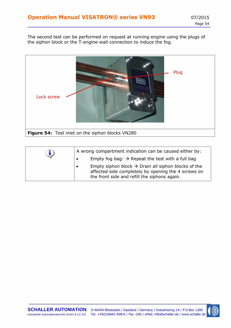
The second test can be performed on request at running engine using the plugs of the siphon block or the T-engine-wall connection to induce the fog.
Figure 54: Test inlet on the siphon blocks VN280
A wrong compartment indication can be caused either by:
Empty fog bag: Repeat the test with a full bag
Empty siphon block Drain all siphon blocks of the
affected side completely by opening the 4 screws on the front side and refill the siphons again.
Lock screw
Plug
Operation Manual VISATRON® series VN93 07/2015
Page 55
SCHALLER AUTOMATION D-66440 Blieskastel / Saarland / Germany / Industriering 14 / P.O Box 1280
Industrielle Automationstechnik GmbH & Co. KG Tel. +49(0)6842-508-0 / Fax -260 / eMail: [email protected] / www.schaller.de
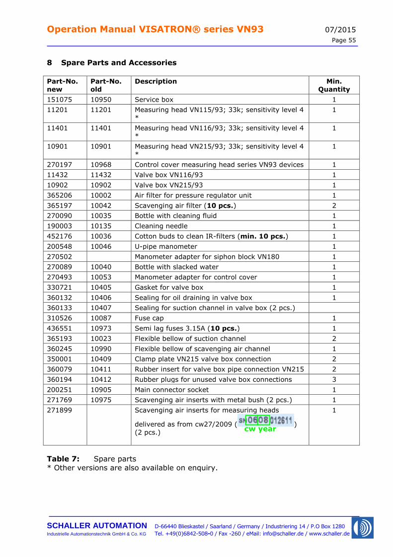
8 Spare Parts and Accessories
Part-No.
new
Part-No.
old
Description Min.
Quantity
151075 10950 Service box 1
11201 11201 Measuring head VN115/93; 33k; sensitivity level 4
*
1
11401 11401 Measuring head VN116/93; 33k; sensitivity level 4
* 1
10901 10901 Measuring head VN215/93; 33k; sensitivity level 4
*
1
270197 10968 Control cover measuring head series VN93 devices 1
11432 11432 Valve box VN116/93 1
10902 10902 Valve box VN215/93 1
365206 10002 Air filter for pressure regulator unit 1
365197 10042 Scavenging air filter (10 pcs.) 2
270090 10035 Bottle with cleaning fluid 1
190003 10135 Cleaning needle 1
452176 10036 Cotton buds to clean IR-filters (min. 10 pcs.) 1
200548 10046 U-pipe manometer 1
270502 Manometer adapter for siphon block VN180 1
270089 10040 Bottle with slacked water 1
270493 10053 Manometer adapter for control cover 1
330721 10405 Gasket for valve box 1
360132 10406 Sealing for oil draining in valve box 1
360133 10407 Sealing for suction channel in valve box (2 pcs.)
310526 10087 Fuse cap 1
436551 10973 Semi lag fuses 3.15A (10 pcs.) 1
365193 10023 Flexible bellow of suction channel 2
360245 10990 Flexible bellow of scavenging air channel 1
350001 10409 Clamp plate VN215 valve box connection 2
360079 10411 Rubber insert for valve box pipe connection VN215 2
360194 10412 Rubber plugs for unused valve box connections 3
200251 10905 Main connector socket 1
271769 10975 Scavenging air inserts with metal bush (2 pcs.) 1
271899 Scavenging air inserts for measuring heads
delivered as from cw27/2009 ( )
(2 pcs.)
1
Table 7: Spare parts
* Other versions are also available on enquiry.
cw year
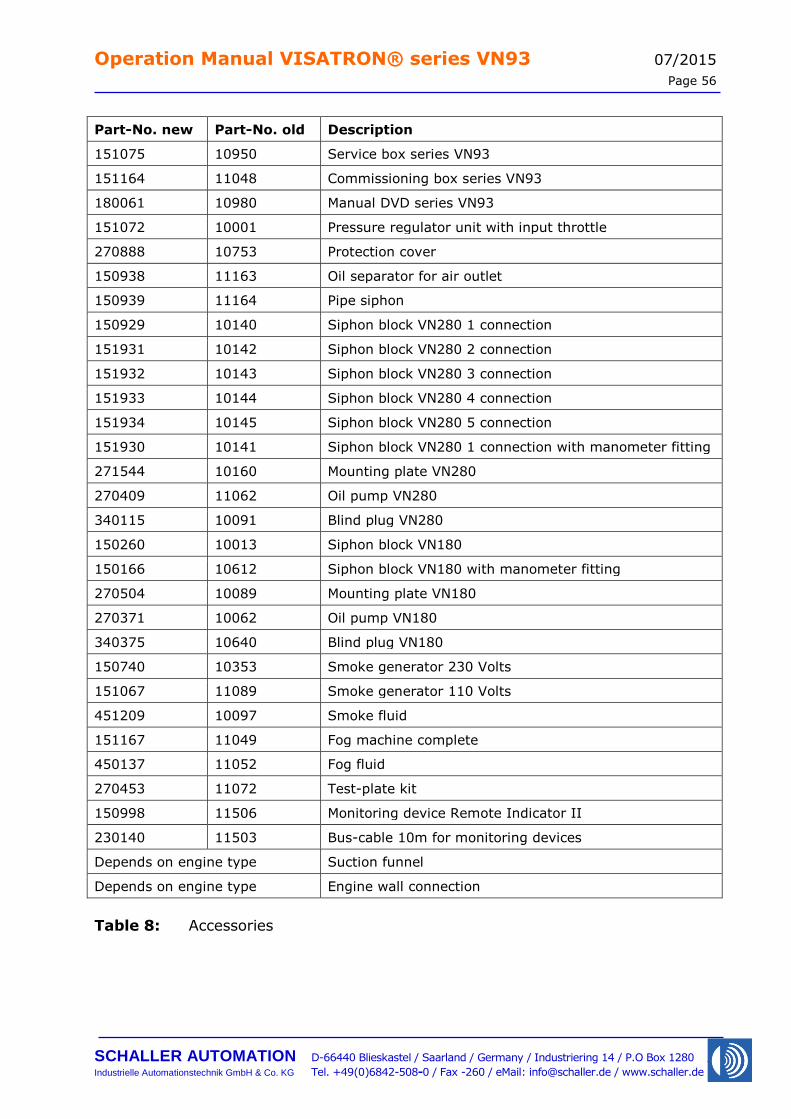
Operation Manual VISATRON® series VN93 07/2015
Page 56
SCHALLER AUTOMATION D-66440 Blieskastel / Saarland / Germany / Industriering 14 / P.O Box 1280
Industrielle Automationstechnik GmbH & Co. KG Tel. +49(0)6842-508-0 / Fax -260 / eMail: [email protected] / www.schaller.de
Part-No. new Part-No. old Description
151075 10950 Service box series VN93
151164 11048 Commissioning box series VN93
180061 10980 Manual DVD series VN93
151072 10001 Pressure regulator unit with input throttle
270888 10753 Protection cover
150938 11163 Oil separator for air outlet
150939 11164 Pipe siphon
150929 10140 Siphon block VN280 1 connection
151931 10142 Siphon block VN280 2 connection
151932 10143 Siphon block VN280 3 connection
151933 10144 Siphon block VN280 4 connection
151934 10145 Siphon block VN280 5 connection
151930 10141 Siphon block VN280 1 connection with manometer fitting
271544 10160 Mounting plate VN280
270409 11062 Oil pump VN280
340115 10091 Blind plug VN280
150260 10013 Siphon block VN180
150166 10612 Siphon block VN180 with manometer fitting
270504 10089 Mounting plate VN180
270371 10062 Oil pump VN180
340375 10640 Blind plug VN180
150740 10353 Smoke generator 230 Volts
151067 11089 Smoke generator 110 Volts
451209 10097 Smoke fluid
151167 11049 Fog machine complete
450137 11052 Fog fluid
270453 11072 Test-plate kit
150998 11506 Monitoring device Remote Indicator II
230140 11503 Bus-cable 10m for monitoring devices
Depends on engine type Suction funnel
Depends on engine type Engine wall connection
Table 8: Accessories
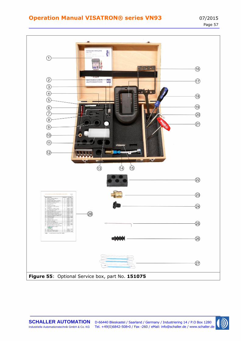
Operation Manual VISATRON® series VN93 07/2015
Page 57
SCHALLER AUTOMATION D-66440 Blieskastel / Saarland / Germany / Industriering 14 / P.O Box 1280
Industrielle Automationstechnik GmbH & Co. KG Tel. +49(0)6842-508-0 / Fax -260 / eMail: [email protected] / www.schaller.de
Figure 55: Optional Service box, part No. 151075
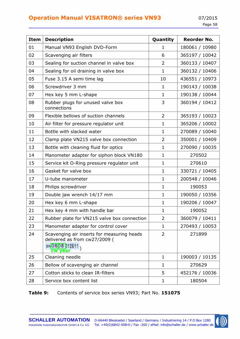
Operation Manual VISATRON® series VN93 07/2015
Page 58
SCHALLER AUTOMATION D-66440 Blieskastel / Saarland / Germany / Industriering 14 / P.O Box 1280
Industrielle Automationstechnik GmbH & Co. KG Tel. +49(0)6842-508-0 / Fax -260 / eMail: [email protected] / www.schaller.de
Item Description Quantity Reorder No.
01 Manual VN93 English DVD-Form 1 180061 / 10980
02 Scavenging air filters 6 365197 / 10042
03 Sealing for suction channel in valve box 2 360133 / 10407
04 Sealing for oil draining in valve box 1 360132 / 10406
05 Fuse 3.15 A semi time lag 10 436551 / 10973
06 Screwdriver 3 mm 1 190143 / 10038
07 Hex key 5 mm L-shape 1 190138 / 10044
08 Rubber plugs for unused valve box
connections
3 360194 / 10412
09 Flexible bellows of suction channels 2 365193 / 10023
10 Air filter for pressure regulator unit 1 365206 / 10002
11 Bottle with slacked water 1 270089 / 10040
12 Clamp plate VN215 valve box connection 2 350001 / 10409
13 Bottle with cleaning fluid for optics 1 270090 / 10035
14 Manometer adapter for siphon block VN180 1 270502
15 Service kit O-Ring pressure regulator unit 1 270610
16 Gasket for valve box 1 330721 / 10405
17 U-tube manometer 1 200548 / 10046
18 Philips screwdriver 1 190053
19 Double jaw wrench 14/17 mm 1 190050 / 10356
20 Hex key 6 mm L-shape 1 190206 / 10047
21 Hex key 4 mm with handle bar 1 190052
22 Rubber plate for VN215 valve box connection 2 360079 / 10411
23 Manometer adapter for control cover 1 270493 / 10053
24 Scavenging air inserts for measuring heads delivered as from cw27/2009 (
)
2 271899
25 Cleaning needle 1 190003 / 10135
26 Bellow of scavenging air channel 1 270629
27 Cotton sticks to clean IR-filters 5 452176 / 10036
28 Service box content list 1 180504
Table 9: Contents of service box series VN93; Part No. 151075
cw year
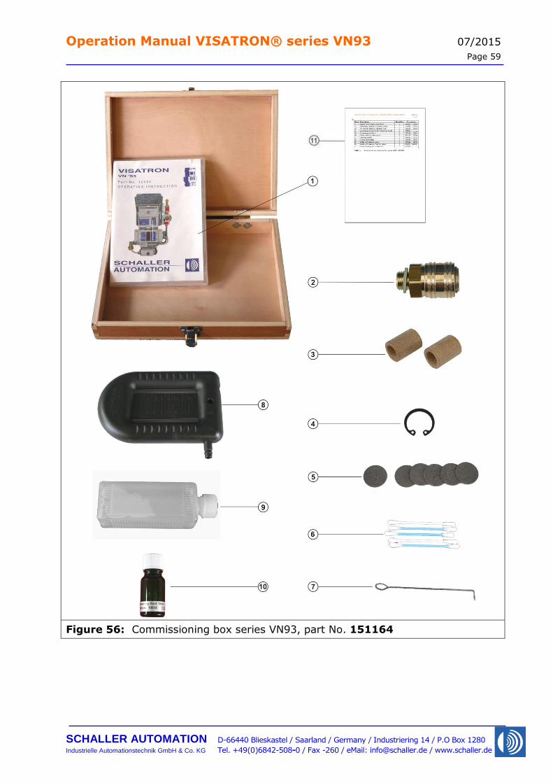
Operation Manual VISATRON® series VN93 07/2015
Page 59
SCHALLER AUTOMATION D-66440 Blieskastel / Saarland / Germany / Industriering 14 / P.O Box 1280
Industrielle Automationstechnik GmbH & Co. KG Tel. +49(0)6842-508-0 / Fax -260 / eMail: [email protected] / www.schaller.de
Figure 56: Commissioning box series VN93, part No. 151164
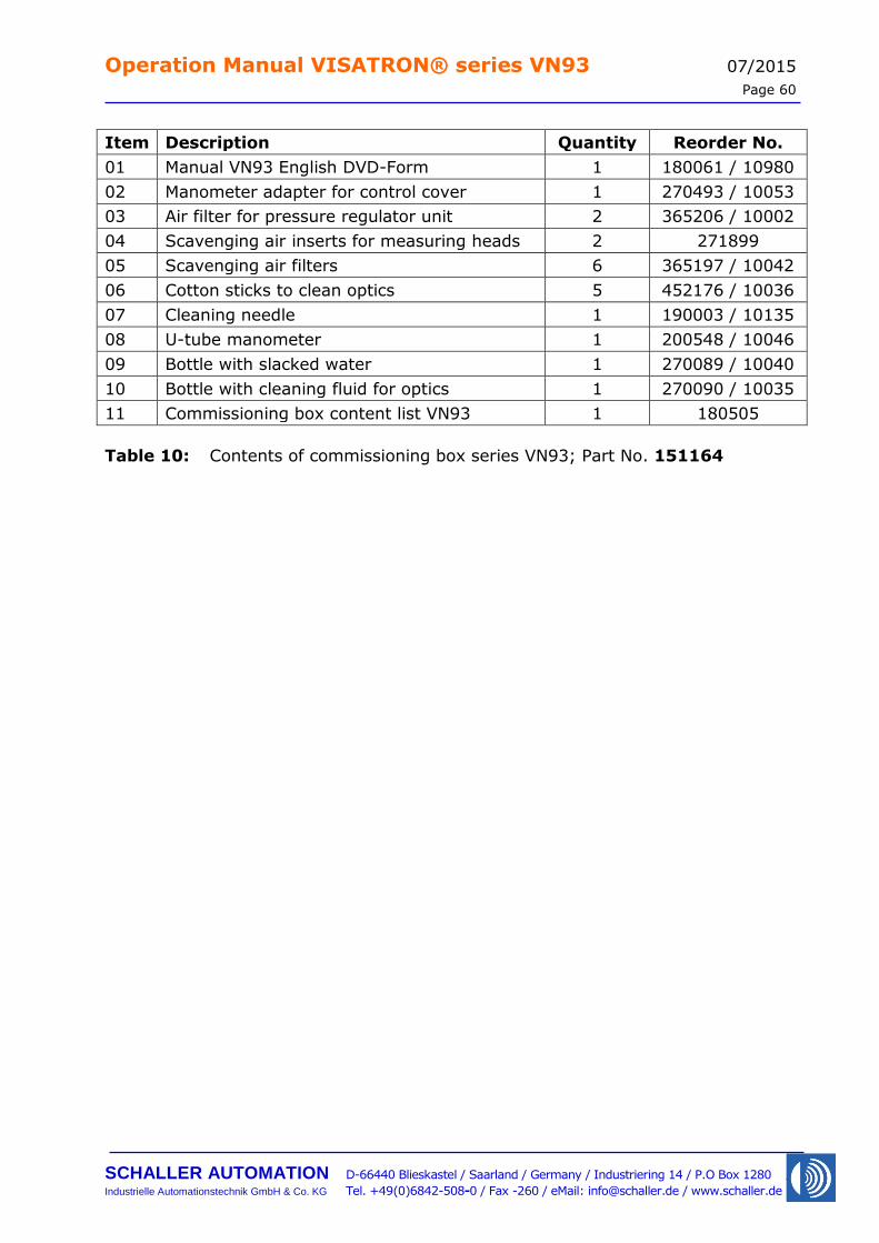
Operation Manual VISATRON® series VN93 07/2015
Page 60
SCHALLER AUTOMATION D-66440 Blieskastel / Saarland / Germany / Industriering 14 / P.O Box 1280
Industrielle Automationstechnik GmbH & Co. KG Tel. +49(0)6842-508-0 / Fax -260 / eMail: [email protected] / www.schaller.de
Item Description Quantity Reorder No.
01 Manual VN93 English DVD-Form 1 180061 / 10980
02 Manometer adapter for control cover 1 270493 / 10053
03 Air filter for pressure regulator unit 2 365206 / 10002
04 Scavenging air inserts for measuring heads 2 271899
05 Scavenging air filters 6 365197 / 10042
06 Cotton sticks to clean optics 5 452176 / 10036
07 Cleaning needle 1 190003 / 10135
08 U-tube manometer 1 200548 / 10046
09 Bottle with slacked water 1 270089 / 10040
10 Bottle with cleaning fluid for optics 1 270090 / 10035
11 Commissioning box content list VN93 1 180505
Table 10: Contents of commissioning box series VN93; Part No. 151164
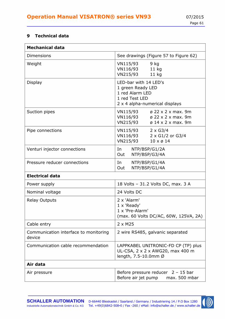
Operation Manual VISATRON® series VN93 07/2015
Page 61
SCHALLER AUTOMATION D-66440 Blieskastel / Saarland / Germany / Industriering 14 / P.O Box 1280
Industrielle Automationstechnik GmbH & Co. KG Tel. +49(0)6842-508-0 / Fax -260 / eMail: [email protected] / www.schaller.de
9 Technical data
Mechanical data
Dimensions See drawings (Figure 57 to Figure 62)
Weight VN115/93 9 kg
VN116/93 11 kg
VN215/93 11 kg
Display LED-bar with 14 LED's
1 green Ready LED
1 red Alarm LED
1 red Test LED
2 x 4 alpha-numerical displays
Suction pipes VN115/93 ø 22 x 2 x max. 9m
VN116/93 ø 22 x 2 x max. 9m
VN215/93 ø 14 x 2 x max. 9m
Pipe connections VN115/93 2 x G3/4
VN116/93 2 x G1/2 or G3/4
VN215/93 10 x ø 14
Venturi injector connections In NTP/BSP/G1/2A
Out NTP/BSP/G3/4A
Pressure reducer connections In NTP/BSP/G1/4A
Out NTP/BSP/G1/4A
Electrical data
Power supply 18 Volts – 31.2 Volts DC, max. 3 A
Nominal voltage 24 Volts DC
Relay Outputs 2 x 'Alarm'
1 x 'Ready'
1 x 'Pre-Alarm'
(max. 60 Volts DC/AC, 60W, 125VA, 2A)
Cable entry 2 x M25
Communication interface to monitoring
device
2 wire RS485, galvanic separated
Communication cable recommendation LAPPKABEL UNITRONIC-FD CP (TP) plus
UL-CSA, 2 x 2 x AWG20, max 400 m
length, 7.5-10.0mm Ø
Air data
Air pressure Before pressure reducer 2 – 15 bar
Before air jet pump max. 500 mbar
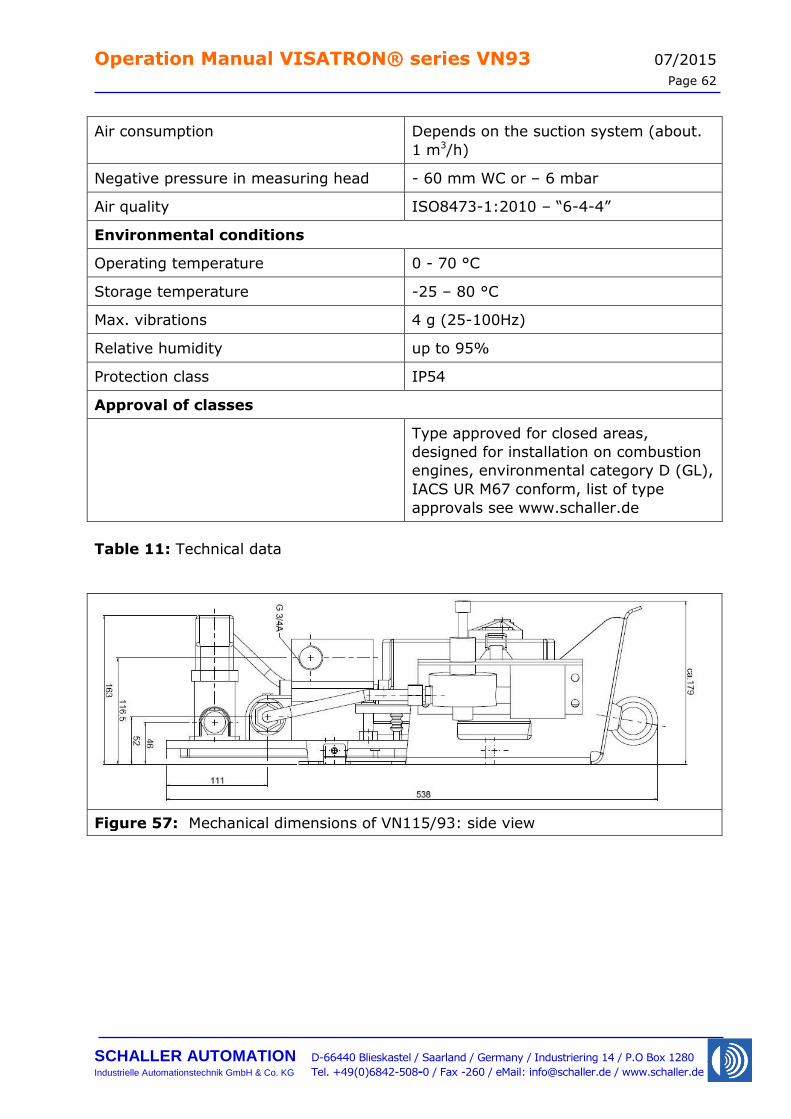
Operation Manual VISATRON® series VN93 07/2015
Page 62
SCHALLER AUTOMATION D-66440 Blieskastel / Saarland / Germany / Industriering 14 / P.O Box 1280
Industrielle Automationstechnik GmbH & Co. KG Tel. +49(0)6842-508-0 / Fax -260 / eMail: [email protected] / www.schaller.de
Air consumption Depends on the suction system (about.
1 m3/h)
Negative pressure in measuring head - 60 mm WC or – 6 mbar
Air quality ISO8473-1:2010 – “6-4-4”
Environmental conditions
Operating temperature 0 - 70 °C
Storage temperature -25 – 80 °C
Max. vibrations 4 g (25-100Hz)
Relative humidity up to 95%
Protection class IP54
Approval of classes
Type approved for closed areas,
designed for installation on combustion
engines, environmental category D (GL),
IACS UR M67 conform, list of type
approvals see www.schaller.de
Table 11: Technical data
Figure 57: Mechanical dimensions of VN115/93: side view
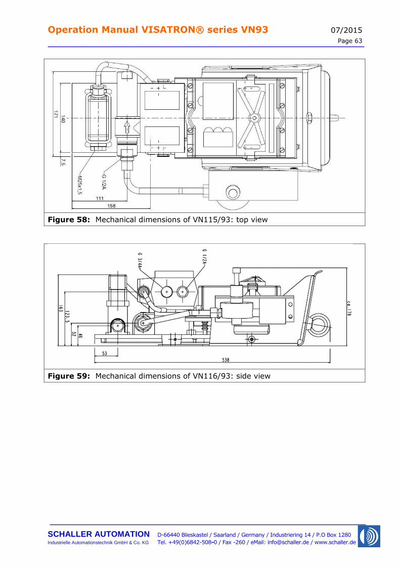
Operation Manual VISATRON® series VN93 07/2015
Page 63
SCHALLER AUTOMATION D-66440 Blieskastel / Saarland / Germany / Industriering 14 / P.O Box 1280
Industrielle Automationstechnik GmbH & Co. KG Tel. +49(0)6842-508-0 / Fax -260 / eMail: [email protected] / www.schaller.de
Figure 58: Mechanical dimensions of VN115/93: top view
Figure 59: Mechanical dimensions of VN116/93: side view
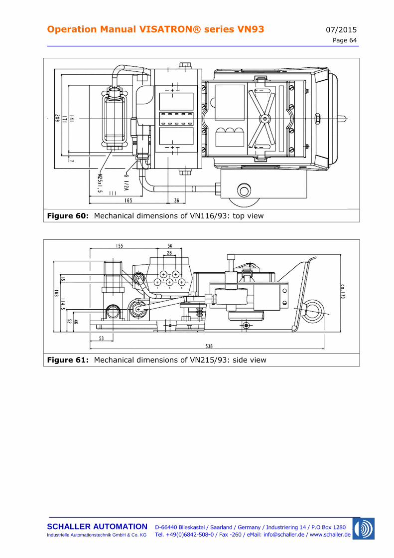
Operation Manual VISATRON® series VN93 07/2015
Page 64
SCHALLER AUTOMATION D-66440 Blieskastel / Saarland / Germany / Industriering 14 / P.O Box 1280
Industrielle Automationstechnik GmbH & Co. KG Tel. +49(0)6842-508-0 / Fax -260 / eMail: [email protected] / www.schaller.de
Figure 60: Mechanical dimensions of VN116/93: top view
Figure 61: Mechanical dimensions of VN215/93: side view
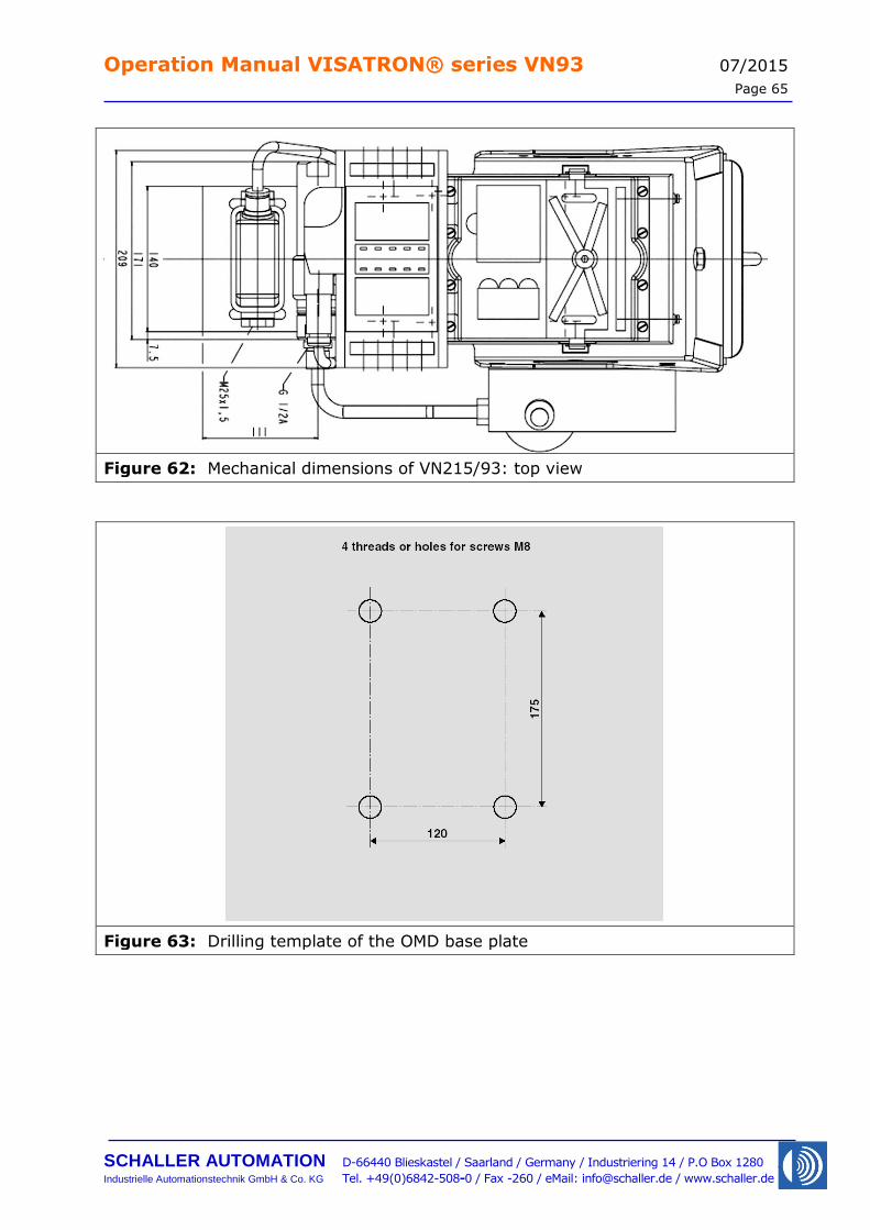
Operation Manual VISATRON® series VN93 07/2015
Page 65
SCHALLER AUTOMATION D-66440 Blieskastel / Saarland / Germany / Industriering 14 / P.O Box 1280
Industrielle Automationstechnik GmbH & Co. KG Tel. +49(0)6842-508-0 / Fax -260 / eMail: [email protected] / www.schaller.de
Figure 62: Mechanical dimensions of VN215/93: top view
Figure 63: Drilling template of the OMD base plate

Operation Manual VISATRON® series VN93 07/2015
Page 66
SCHALLER AUTOMATION D-66440 Blieskastel / Saarland / Germany / Industriering 14 / P.O Box 1280
Industrielle Automationstechnik GmbH & Co. KG Tel. +49(0)6842-508-0 / Fax -260 / eMail: [email protected] / www.schaller.de
10 Service Partners
Schaller Automation maintains a worldwide network of service partners currently in the following countries:
Australia Brazil
Canada Chile
China Denmark
Germany Greece
Italy Japan
Korea Netherlands
Norway
Poland Singapore
Spain Taiwan
Turkey United Arabian Emirates
United Kingdom United States of America
For an up-to-date list of our representatives including address and contact details please visit our website:
www.schaller.de Alternatively, you may call the German headquarters for assistance in locating your
nearest representative.
Tel. +49 (0)6842 508 0