oil sea harvester project osh design : hydrodynamics and optimisation
DESCRIPTION
Oil Sea Harvester Project OSH design : Hydrodynamics and Optimisation. Partners involved : CAT Shipyard (FR) : Design BEC hydrodynamic laboratory (FR) : Numerical optimisation CEHIPAR hydrodynamic laboratory (SP) : Test campaigns. Transit phase - PowerPoint PPT PresentationTRANSCRIPT

OSH PMC MEETING N°7 9 th June 2006, Athens (GR)
OIL SEA HARVESTER
TST4-CT-2004-516230
www.osh-project.org
Oil Sea Harvester Project
OSH design : Hydrodynamics and Optimisation
Partners involved :• CAT Shipyard (FR) : Design• BEC hydrodynamic laboratory (FR) : Numerical optimisation• CEHIPAR hydrodynamic laboratory (SP) : Test campaigns

OSH PMC MEETING N°7 9 th June 2006, Athens (GR)
OIL SEA HARVESTER
TST4-CT-2004-516230
www.osh-project.org
General Objective :Optimisation of the operational
performances of the OSH concept
• Transit phase– Powering performances : relatively high transit speed
– Sea-keeping behaviour : low dynamic responses
• Oil recovery Phase– Sea-keeping behaviour for oil recovery operations up to sea state
6/7
OSH PMC MEETING N°7 9 th June 2006, Athens (GR)
OIL SEA HARVESTER
TST4-CT-2004-516230
www.osh-project.org
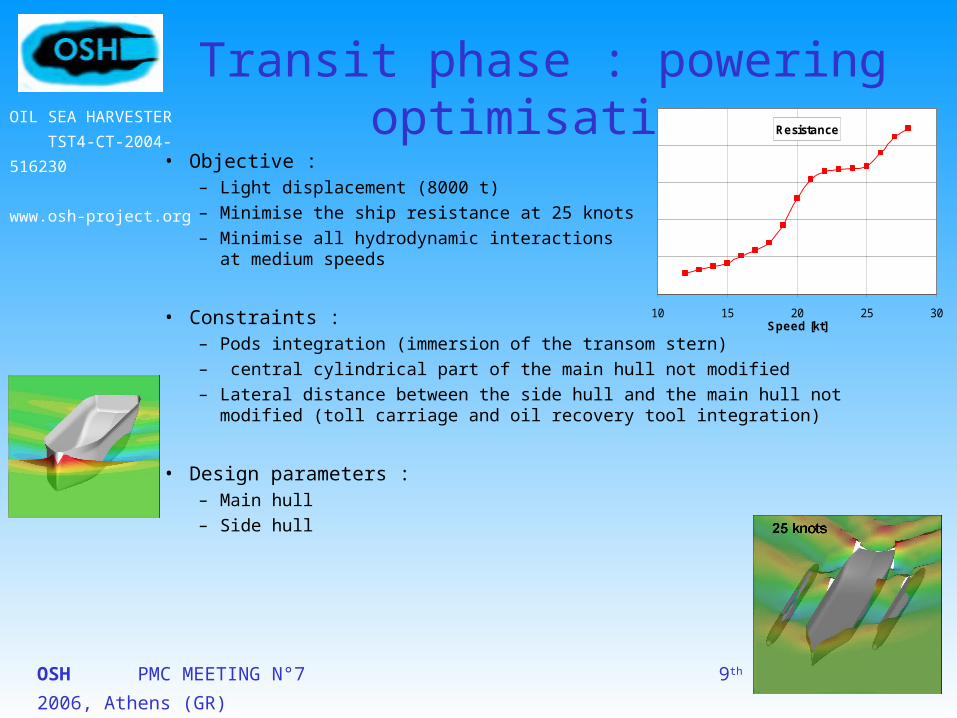
Transit phase : powering optimisation
• Objective :– Light displacement (8000 t)– Minimise the ship resistance at 25 knots– Minimise all hydrodynamic interactions
at medium speeds
• Constraints :– Pods integration (immersion of the transom stern)– central cylindrical part of the main hull not modified– Lateral distance between the side hull and the main hull not modified (toll carriage
and oil recovery tool integration)
• Design parameters :– Main hull– Side hull
Resistance
10 15 20 25 30Speed [kt]

OSH PMC MEETING N°7 9 th June 2006, Athens (GR)
OIL SEA HARVESTER
TST4-CT-2004-516230
www.osh-project.org
Powering optimisation : Main hull modifications
• Bow sections : thinner waterline
• Buttock line and transom immersion
• Bulbous bow
Initial
FinalOptimal
Initial Final
Initial
Final
Initial form

OSH PMC MEETING N°7 9 th June 2006, Athens (GR)
OIL SEA HARVESTER
TST4-CT-2004-516230
www.osh-project.org
Powering optimisation : Side hull modifications
• Best length : 101m (initial)
• Best longitudinal location : fore
80 m
101 m
138 m
120 m
Main hull
Side hull
Initialside hull
AP FP
Best compromise between bow wave interactionsand stern wave interactions
0.0E+00
5.0E+05
1.0E+06
1.5E+06
2.0E+06
12 14 16 18 20 22 24 26 28
Speed [kt]
Res
ista
nce
[N
]
Avant
-10
-20
Arrière
19 knots 25 knots
Fore
Aft

OSH PMC MEETING N°7 9 th June 2006, Athens (GR)
OIL SEA HARVESTER
TST4-CT-2004-516230
www.osh-project.org
Sea-keeping optimisation• Objective : sea-keeping performances
– Transit phase :V ≈20 knots - = 8 000 t Tool carriage in folded position
– Oil recovery operations :V : low speed = 12 000 tTool carriage deployed
• Constraints :– Pods integration– cylindrical part of the main hull not modified– distance between the side hull and the main hullnot modified (tool carriage integration)
• Design parameters :– Side hull– Tool carriage
OSH PMC MEETING N°7 9 th June 2006, Athens (GR)
OIL SEA HARVESTER
TST4-CT-2004-516230
www.osh-project.org
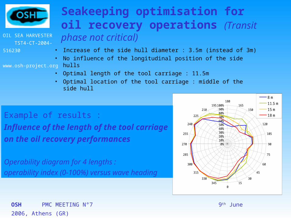
Seakeeping optimisation for oil recovery operations (Transit phase not critical)
• Increase of the side hull diameter : 3.5m (instead of 3m)
• No influence of the longitudinal position of the side hulls
• Optimal length of the tool carriage : 11.5m
• Optimal location of the tool carriage : middle of the side hull
0%10%20%30%40%50%60%70%80%90%
100%180
165150
135
120
105
90
75
60
45
3015
0345
330
315
300
285
270
255
240
225
210195
8 m
11.5 m
15 m
18 m
Following waves (0°)
Bea
m p
ort
said
e w
aves
(27
0°) B
eam starb
oard
waves (90°)
Head waves (180°)
Example of results :
Influence of the length of the tool carriage
on the oil recovery performances
Operability diagram for 4 lengths :
operability index (0-100%) versus wave heading

OSH PMC MEETING N°7 9 th June 2006, Athens (GR)
OIL SEA HARVESTER
TST4-CT-2004-516230
www.osh-project.org
0%10%20%30%40%50%60%70%80%90%
100%180
165150
135
120
105
90
75
60
45
3015
0345
330
315
300
285
270
255
240
225
210195
Initial
Optimal
Following waves (0°)
Bea
m p
ort
said
e w
aves
(27
0°) B
eam starb
oard
waves (90°)
Head waves (180°)
Optimal design• Thinner bow sections
• Maximum transom immersion
• (Bulbous bow)
• Side hulls of length 101m at extreme fore location
• Tool carriage of length 11.5m located in the middle of the side hull

OSH PMC MEETING N°7 9 th June 2006, Athens (GR)
OIL SEA HARVESTER
TST4-CT-2004-516230
www.osh-project.org
Tank tests in progress (task 5.3)- assessment of the design optimised numerically- calibration of the numerical tools (re-used for the final design stage)
• Resistance tests almost completed– Great importance of the static trim
(transom immersion)
– Optimal location of the side hull : fore
Ship resistance (model)
0
5
10
15
20
25
30
0.0 0.5 1.0 1.5 2.0 2.5 3.0Speed [m/s]
Res
ista
nce
[kg
]
Trim 0m
Trim 2m
Trim 4m
Ship resistance (model)
0
5
10
15
20
25
30
0.0 0.5 1.0 1.5 2.0 2.5 3.0Speed [m/s]
Res
ista
nce
[kg
]
Fore position
5m aft
10m aft
Influence of the static trim
Influence of the longitudinal Side hull location
• Seakeeping tests carried out from June to September 06

OSH PMC MEETING N°7 9 th June 2006, Athens (GR)
OIL SEA HARVESTER
TST4-CT-2004-516230
www.osh-project.org
Thank you for your attention

OSH PMC MEETING N°7 9 th June 2006, Athens (GR)
OIL SEA HARVESTER
TST4-CT-2004-516230
www.osh-project.org
Seakeeping optimisation
• Definition of the operability value
• Transit phase– Roll < 12°
– Pitch < 4.5°
– Vertical acceleration < 3m/s²
• Oil recovery operations– Wave elevation < 1m
– Relative heave < 3m
– Vertical acceleration < 3m/s²
• Maximum significant height
• Operability diagramm
>14 0.0 0.0 0.1 0.2 0.2 0.1 0.1 0.0
13-14 0.0 0.0 0.1 0.1 0.1 0.1 0.0 0.0
12-13 0.0 0.1 0.1 0.2 0.2 0.1 0.0 0.0
11-12 0.0 0.0 0.1 0.2 0.3 0.3 0.2 0.1 0.0
10-11 0.0 0.0 0.2 0.4 0.5 0.4 0.2 0.1 0.0
9-10 0.0 0.1 0.4 0.8 1.0 0.7 0.4 0.1 0.0
8-9 0.0 0.2 0.8 1.6 1.7 1.2 0.6 0.2 0.1
7-8 0.0 0.4 1.8 3.2 3.1 2.0 0.9 0.3 0.1
6-7 0.0 0.1 1.1 4.0 6.5 5.8 3.4 1.5 0.5 0.1
5-6 0.0 0.3 2.9 9.3 13.3 10.7 5.7 2.2 0.7 0.2
4-5 0.0 1.0 7.9 21.3 26.3 18.5 8.7 3.0 0.8 0.2
3-4 0.1 3.2 20.8 45.6 46.9 28.0 11.3 3.4 0.8 0.2
2-3 0.0 0.5 10.3 48.9 81.6 65.6 31.5 10.4 2.6 0.5 0.1
1-2 0.0 2.2 28.5 84.3 93.4 52.4 18.2 4.5 0.9 0.1 0.0
0-1 0.4 8.9 34.1 43.3 24.8 7.9 1.7 0.3 0.0 0.0
<4 4-5 5-6 6-7 7-8 8-9 9-10 10-11 11-12 12-13 >13Zero crossing period (s)
Sig
nif
ican
t w
ave
hei
gh
t (m
)
SS 7
SS 8
SS 6
SS 5
SS 4
PilRel RelWave Zacc
Statistiques du Golfe de Gascogne
71.8%
0%10%20%30%40%50%60%70%80%90%
100%Relative wave
Relative waveRelative wave
Relative wave
Relative heave
Relative heave
Relative heave
Relative heave
Relative wave
Relative wave
Relative waveRelative wave
Relative waveRelative wave
Relative heave
Relative heave
Relative heave
Vertical acceleration
Vertical acceleration
Vertical acceleration
Vertical acceleration
Relative heave
Relative waveRelative wave
Following waves (0°)
Bea
m p
ort
said
e w
aves
(27
0°) B
eam starb
oard
waves (90°)
Head waves (180°)
Quantity of oil spilled (tonnes) :
50 to 500
500 to 10 000
> 10 000

OSH PMC MEETING N°7 9 th June 2006, Athens (GR)
OIL SEA HARVESTER
TST4-CT-2004-516230
www.osh-project.org
Seakeeping optimisation Transit phase
• Better performances than in oil recovery operations
• No need to optimise
0%10%20%30%40%50%60%70%80%90%
100%180
165150
135
120
105
90
75
60
45
3015
0345
330
315
300
285
270
255
240
225
210195
Oil recovery
Transit
Following waves (0°)
Bea
m p
ort
said
e w
aves
(27
0°) B
eam starb
oard
waves (90°)
Head waves (180°)

OSH PMC MEETING N°7 9 th June 2006, Athens (GR)
OIL SEA HARVESTER
TST4-CT-2004-516230
www.osh-project.org
Seakeeping optimisation Oil recovery operations
• Increase of the side hull diameter :3.5m
• No influence of the longitudinal position of the side hulls
• Optimal length of the tool carriage : 11.5m
• Optimal location of the tool carriage : middle if the side hull
0%10%20%30%40%50%60%70%80%90%
100%180
165150
135
120
105
90
75
60
45
3015
0345
330
315
300
285
270
255
240
225
210195
8 m
11.5 m
15 m
18 m
Following waves (0°)
Bea
m p
ort
said
e w
aves
(27
0°) B
eam starb
oard
waves (90°)
Head waves (180°)
0%10%20%30%40%50%60%70%80%90%
100%180
165150
135
120
105
90
75
60
45
3015
0345
330
315
300
285
270
255
240
225
210195
-16 m-8 mInitial+10 m+20 m
Following waves (0°)B
eam
po
rtsa
ide
wav
es (
270°
) Beam
starbo
ard w
aves (90°)
Head waves (180°)
Lngitudinal location of the side hullsLength of the tool carriage