oilfield data handbook - monarch supply ltd
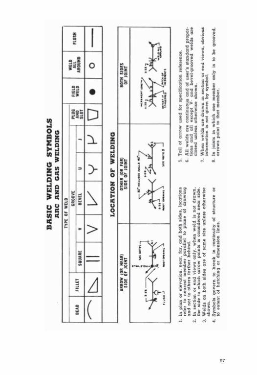
TRANSCRIPT

PERSONAL NOTES
Name:....................................................................................................................................
Home Address: ....................................................................................................................
..................................................................................Phone..................................................
Business Address: ................................................................................................................
..................................................................................Phone..................................................
Telex ............................................................................Fax..................................................
Nat. Ins. or Social Security No.............................................................................................
Driver’s License No. ............................................................................................................
Car Registration No. ............................................................................................................
Passport No...........................................................................................................................
Credit Cards(s)......................................................................................................................
Checking Account(s) ............................................................................................................
In Case of Accident Please Notify........................................................................................
..................................................................................Phone..................................................
Important Medical Information
Blood Type............................................................................................................................
Doctor ..................................................................................................................................
..................................................................................Phone..................................................
Hospital Insurance Policy No...............................................................................................
Special Instructions ..............................................................................................................
..............................................................................................................................................
..............................................................................................................................................
..............................................................................................................................................
..............................................................................................................................................
..............................................................................................................................................
1
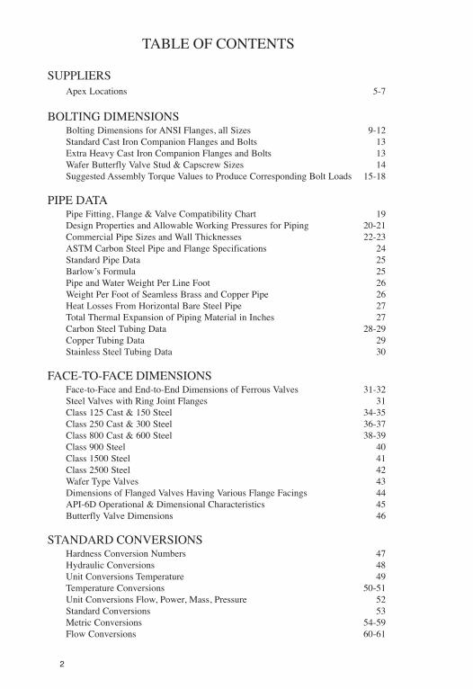
TABLE OF CONTENTS
SUPPLIERSApex Locations 5-7
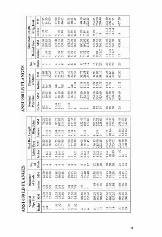
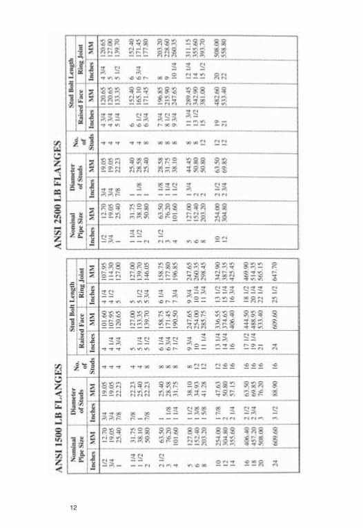
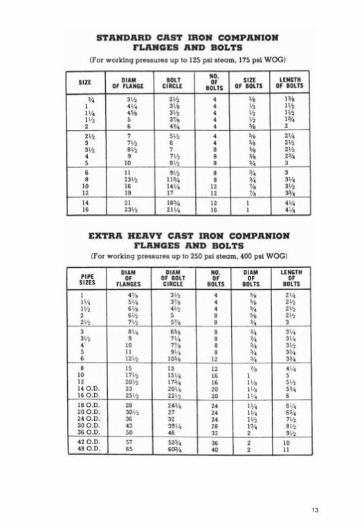
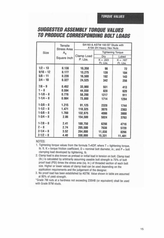
BOLTING DIMENSIONSBolting Dimensions for ANSI Flanges, all Sizes 9-12Standard Cast Iron Companion Flanges and Bolts 13Extra Heavy Cast Iron Companion Flanges and Bolts 13Wafer Butterfly Valve Stud & Capscrew Sizes 14Suggested Assembly Torque Values to Produce Corresponding Bolt Loads 15-18
PIPE DATAPipe Fitting, Flange & Valve Compatibility Chart 19Design Properties and Allowable Working Pressures for Piping 20-21Commercial Pipe Sizes and Wall Thicknesses 22-23ASTM Carbon Steel Pipe and Flange Specifications 24Standard Pipe Data 25Barlow’s Formula 25Pipe and Water Weight Per Line Foot 26Weight Per Foot of Seamless Brass and Copper Pipe 26Heat Losses From Horizontal Bare Steel Pipe 27Total Thermal Expansion of Piping Material in Inches 27Carbon Steel Tubing Data 28-29Copper Tubing Data 29Stainless Steel Tubing Data 30
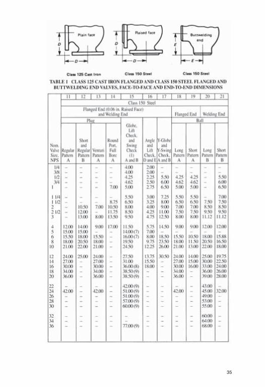
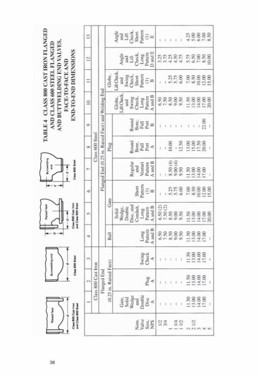
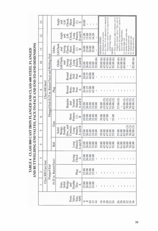
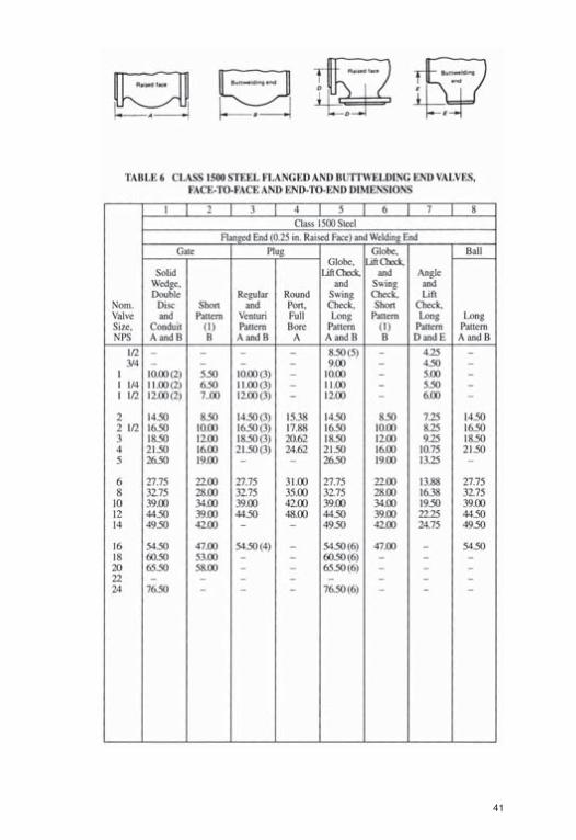
FACE-TO-FACE DIMENSIONSFace-to-Face and End-to-End Dimensions of Ferrous Valves 31-32Steel Valves with Ring Joint Flanges 31Class 125 Cast & 150 Steel 34-35Class 250 Cast & 300 Steel 36-37Class 800 Cast & 600 Steel 38-39Class 900 Steel 40Class 1500 Steel 41Class 2500 Steel 42Wafer Type Valves 43Dimensions of Flanged Valves Having Various Flange Facings 44API-6D Operational & Dimensional Characteristics 45Butterfly Valve Dimensions 46
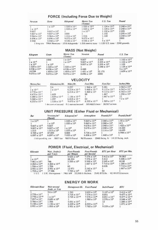
STANDARD CONVERSIONSHardness Conversion Numbers 47Hydraulic Conversions 48Unit Conversions Temperature 49Temperature Conversions 50-51Unit Conversions Flow, Power, Mass, Pressure 52Standard Conversions 53Metric Conversions 54-59Flow Conversions 60-61
2
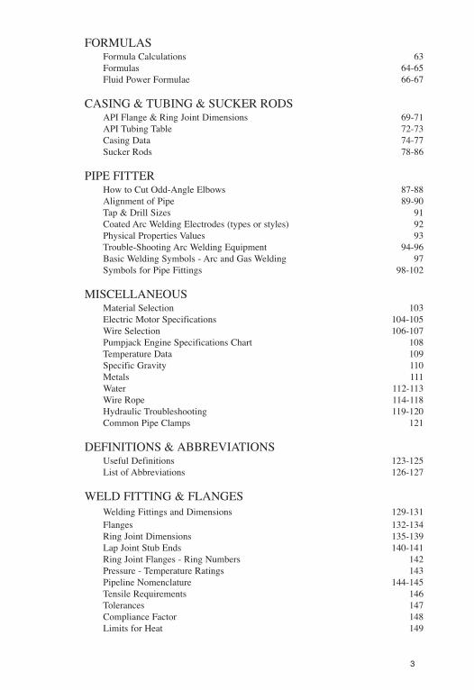
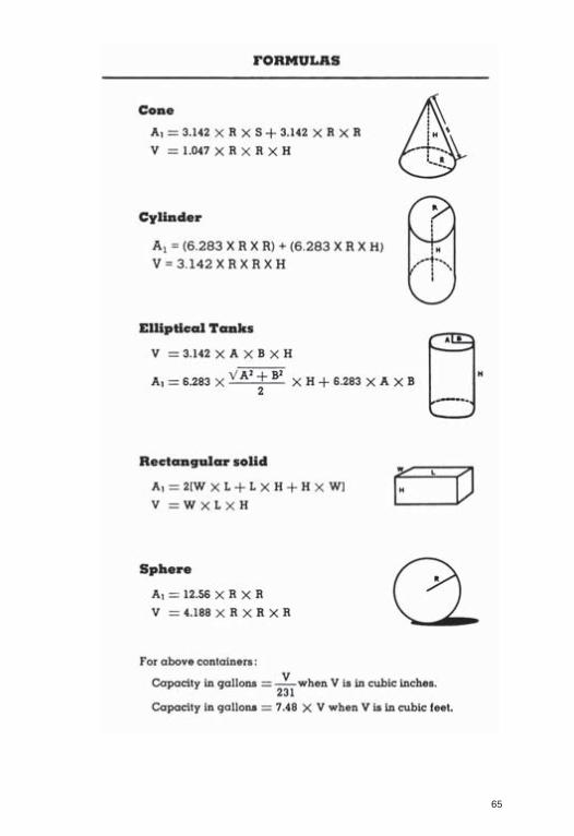
FORMULASFormula Calculations 63Formulas 64-65Fluid Power Formulae 66-67
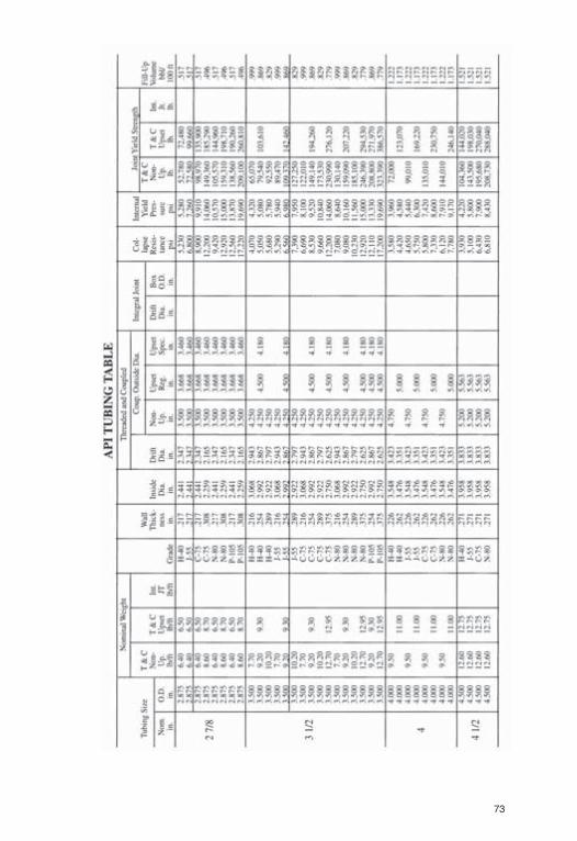
CASING & TUBING & SUCKER RODSAPI Flange & Ring Joint Dimensions 69-71API Tubing Table 72-73Casing Data 74-77Sucker Rods 78-86
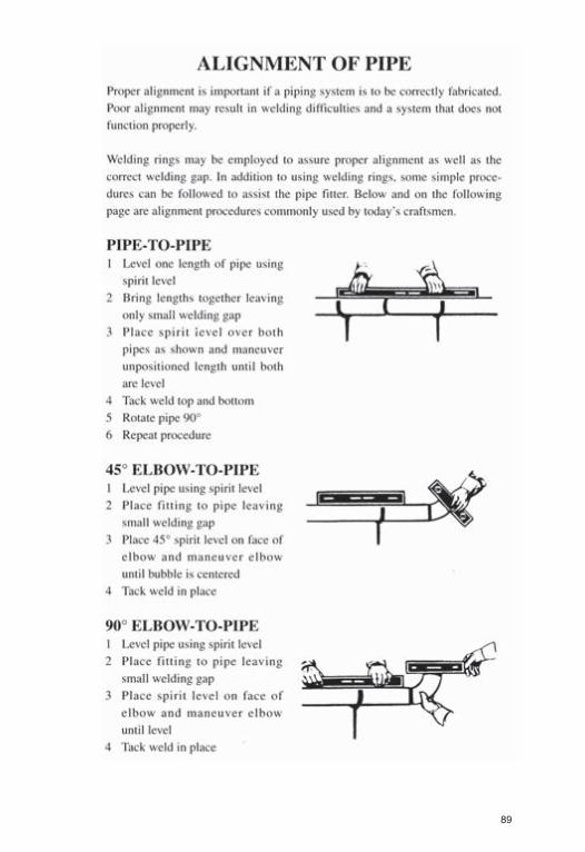
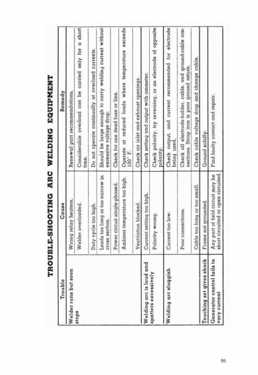
PIPE FITTERHow to Cut Odd-Angle Elbows 87-88Alignment of Pipe 89-90Tap & Drill Sizes 91Coated Arc Welding Electrodes (types or styles) 92Physical Properties Values 93Trouble-Shooting Arc Welding Equipment 94-96Basic Welding Symbols - Arc and Gas Welding 97Symbols for Pipe Fittings 98-102
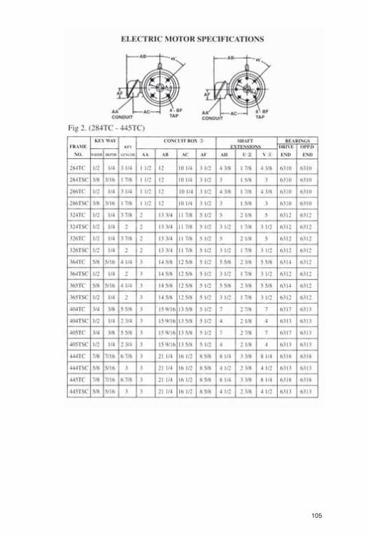
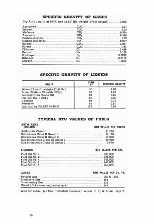
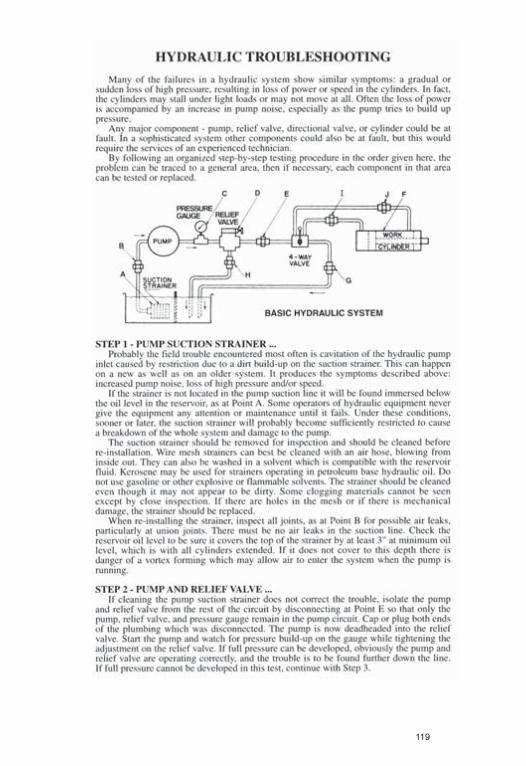
MISCELLANEOUSMaterial Selection 103Electric Motor Specifications 104-105Wire Selection 106-107Pumpjack Engine Specifications Chart 108Temperature Data 109Specific Gravity 110Metals 111Water 112-113Wire Rope 114-118Hydraulic Troubleshooting 119-120Common Pipe Clamps 121
DEFINITIONS & ABBREVIATIONSUseful Definitions 123-125List of Abbreviations 126-127
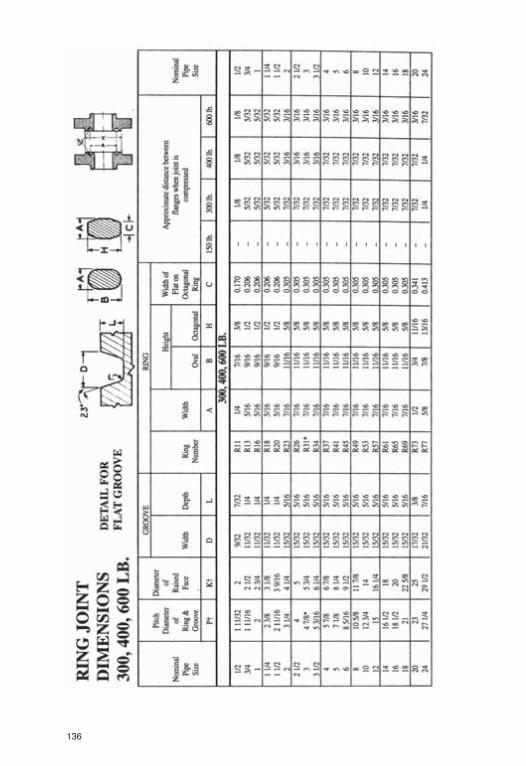
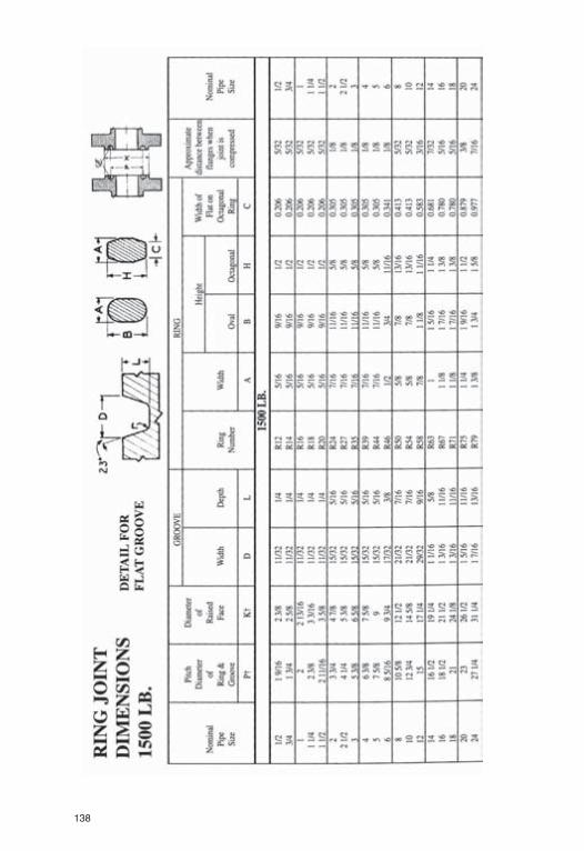
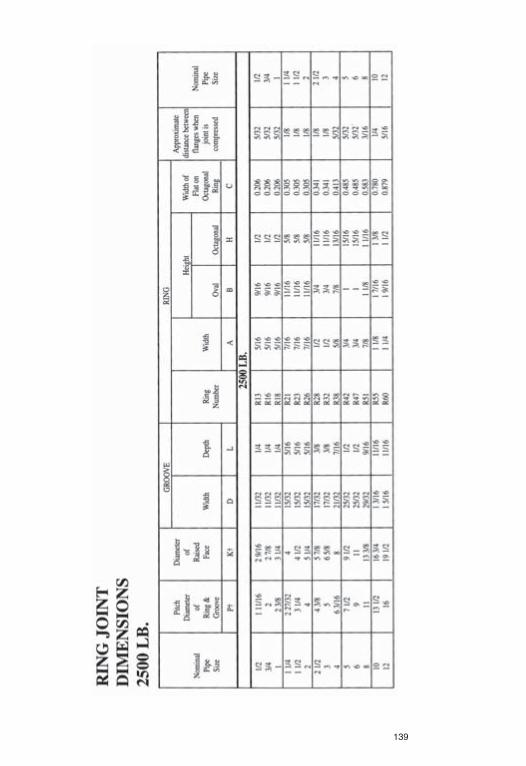
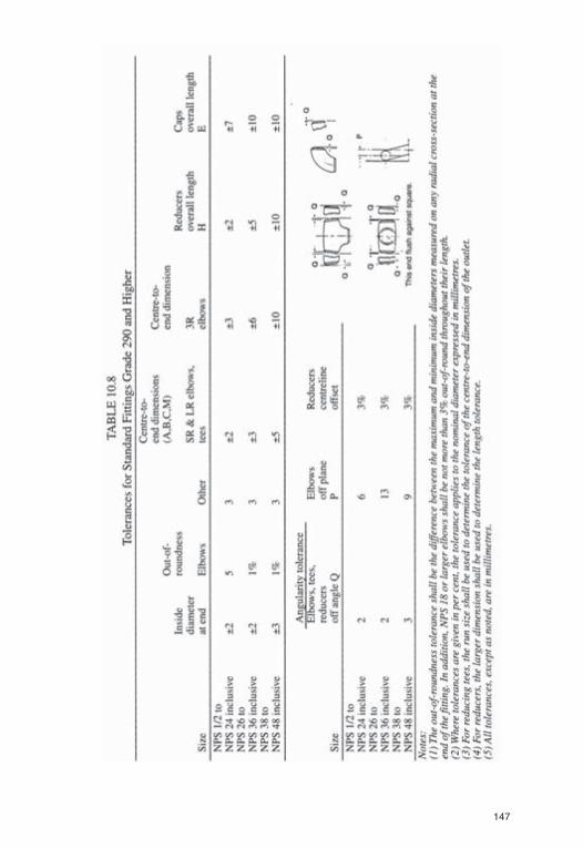
WELD FITTING & FLANGESWelding Fittings and Dimensions 129-131Flanges 132-134Ring Joint Dimensions 135-139Lap Joint Stub Ends 140-141Ring Joint Flanges - Ring Numbers 142Pressure - Temperature Ratings 143Pipeline Nomenclature 144-145Tensile Requirements 146Tolerances 147Compliance Factor 148Limits for Heat 149
3

– NOTICE OF DISCLAIMER OF LIABILITY –
Every precaution has been taken to ensure the accuracyof this data. However, due to the innumerablecalculations and conversions, users are advised to usediscretion. Where extremely detailed data is required,suppliers of A.P.I. Specifications should be consulted.
The information contained in this booklet is provided asa service to assist uers. Apex Distribution Inc. will not beliable for any damages resulting from the use or misuseof any information contained in this booklet. Each usermust assume full responsibility and liability for the useof information in this booklet.
4
5
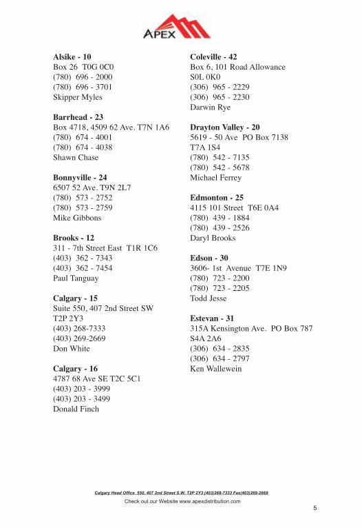
Calgary Head Office 550, 407 2nd Street S.W. T2P 2Y3 (403)268-7333 Fax(403)269-2669
Check out our Website www.apexdistribution.com
Alsike - 10Box 26 T0G 0C0(780) 696 - 2000(780) 696 - 3701Skipper Myles
Barrhead - 23Box 4718, 4509 62 Ave. T7N 1A6(780) 674 - 4001(780) 674 - 4038Shawn Chase
Bonnyville - 246507 52 Ave. T9N 2L7(780) 573 - 2752(780) 573 - 2759Mike Gibbons
Brooks - 12311 - 7th Street East T1R 1C6(403) 362 - 7343(403) 362 - 7454Paul Tanguay
Calgary - 15Suite 550, 407 2nd Street SWT2P 2Y3(403) 268-7333(403) 269-2669Don White
Calgary - 164787 68 Ave SE T2C 5C1(403) 203 - 3999(403) 203 - 3499Donald Finch
Coleville - 42Box 6, 101 Road AllowanceS0L 0K0(306) 965 - 2229(306) 965 - 2230Darwin Rye
Drayton Valley - 205619 - 50 Ave PO Box 7138T7A 1S4(780) 542 - 7135(780) 542 - 5678Michael Ferrey
Edmonton - 254115 101 Street T6E 0A4(780) 439 - 1884(780) 439 - 2526Daryl Brooks
Edson - 303606- 1st Avenue T7E 1N9(780) 723 - 2200(780) 723 - 2205Todd Jesse
Estevan - 31315A Kensington Ave. PO Box 787S4A 2A6(306) 634 - 2835(306) 634 - 2797Ken Wallewein

6
Calgary Head Office 550, 407 2nd Street S.W. T2P 2Y3 (403)268-7333 Fax(403)269-2669
Check out our Website www.apexdistribution.com
Fort St. John - 508507 - 100 Street V1J 3M7(250) 787 - 0929(250) 787 - 0959Scott Bruvold
Fox Creek- 27307 - 1A Ave. T0H 1P0(780) 622 - 2344(780) 622 - 2349Jim Weiten
Grande Prairie - 3610905 - 96 Ave T8V 3J4(780) 513 - 1909(780) 513 - 1553Kevin Stafford
Gull Lake - 43Box 614, Queens Ave S0N 1A0(306) 672 - 4044(306) 672 - 3384Kevin Stafford
Hinton - 29243 Felaber Road T7V 1Z8(780) 865 - 5599(780) 865 - 1552Kyle Beier
Kindersley - 651201 - 11 Ave West PO Box 2140S0L 1S0(306) 463 - 6340(306) 463 - 6551Derek Semple
Lac La Biche - 40# 36 Bypass Road Highway 55PO Box 2635 T0A 2C0(780) 623 - 9610(780) 623 - 9630Pierre Biron
Lloydminster - 225109 62 Street T9V 2E3(780) 875 - 4048(780) 875 - 4156Ryan Pynten
Neilburg - 382 Williams Industrial DrivePO Box #7 S0M 2C0(306) 823 - 4966(306) 823 - 4577Pat Warkentin
Peace River - 418703 75 Street, PO Box 6927T8S 1S6(780) 624 - 0035(780) 624 - 3295David Bentley
Pouce Coupe - 495011 50 Ave V0C 2C0(250) 786-5497(250) 786-5412Lance Hayter
Provost - 343619-57 Ave T0B 3S0(780) 753 - 2558(780) 753 - 6899Dwayne Chopek, Dan Gartner

Calgary Head Office 550, 407 2nd Street S.W. T2P 2Y3 (403)268-7333 Fax(403)269-2669
Check out our Website www.apexdistribution.com
Red Deer - 757764 Edgar Industrial Way T4P 3R2(403) 346 - 3300(403) 346 - 4222Norm Lougheed
Red Earth - 32#210, Highway 88 T0G 1X0(780) 649 - 2122(780) 649 - 2142Kevin Lemay
Regina - 55305 Hodsman Rd S4N 5W5(306)- 721-0762(306) 721-0767Brian Horaska
Rocky Mountain House - 334312 - 46 Ave PO Box 1832T4T 1B4(403) 844 - 4644(403) 844 - 4649Leonard Levinsky
Saskatoon - 603127 Faithfull Ave S7K 8H4(306) 664-2739(306) 664- 2733Garth Huber
Shaunavon - 54PO Box 1204, 713 Highway 73S0N 2M0(306) 297 - 3722(306) 297 - 3724Brad Campbell
Slave Lake - 35Box 509 905 - 3rd Street NWT0G 2A0(780) 849 - 6111(780) 849 - 6114Ken Hedin, Joe MacDougall
Swift Current - 522017 Sidney Street West S9H 5K3(306) 773 - 7227(306) 773 - 4128Ryan Butt, Dan Gartner
Three Hills - 18PO Box 327, 420 3rd Ave SouthT0M 2A0(780) 443 - 7227(780) 443 - 7225Mike Chambers
Wabasca - 371111 Industrial Way T0G 2K0(780) 891-2654(780) 891-2675Landon Yurko
Weyburn - 56PO Box 1586, 40B 18 Street NES4H 0T1(306) 842 - 5081(306) 842 - 5309Larry Paterson
Whitecourt - 46Box 1835, 3507 41 Ave T7S 1P6(780) 778 - 8466(780) 778 - 3566Keith Ratzalff
7

8
Calgary Head Office 550, 407 2nd Street S.W. T2P 2Y3 (403)268-7333 Fax(403)269-2669
Check out our Website www.apexdistribution.com
Actuation
Edmonton - 254115 101 Street T6E 0A4(780) 466 - 2600(780) 466 - 2609Todd Critch / Mike Griffin /Wanda Overacker
Red Deer - 77#5 7499 Edgar Industrial BendT4P 3R2(403) 343 - 6600(403) 343 - 0065Todd Critch
Service and Repair
Bonnyville - 726217 50 Ave. T9N 2L9(780) 826 - 4355(780) 826 - 3153Rick Paradis
Grande Prairie - 81Bay 101, 11281 89 AvenueT8V 5Z2(780) 513 - 2044(780) 539 - 1912Jake Dyck
High Level - 7910508 93 Street T0H 1Z0(780) 926 - 1900(780) 926 - 1902Chris Osmond
Peace River - 802km North on Weberville RdPO Box 5219, Bay #2 T8S 1R8(780) 624 - 5447(780) 624 - 5448Joel Eisan
Slave Lake - 78908 - 6 Street NW Box 446T0G 2A0(780) 849 - 3432(780) 849 - 6166Jennifer MacDonald
Apex Value Services

BOLTINGDIMENSIONS
FORANSIFLANGES
ALLSIZESASPER
ANSIB16.5-1988
Updatedand
Revised
September1997
9

10
11
12
13

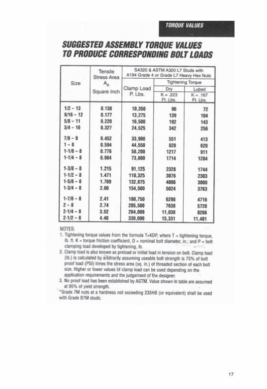
WAFER BUTTERFLY VALVE STUD& CAPSCREW SIZES
150 lb. Threaded Lug Type
No. of Capscrew Length ofValve Size Capscrews Diam. Capscrews
2 4 5/8 1 1/42 1/2 4 5/8 1 1/2
3 4 5/8 1 1/24 16 5/8 1 3/45 16 3/4 1 3/46 16 3/4 1 3/48 16 3/4 210 24 7/8 2 1/412 24 7/8 2 1/414 24 1 2 1/216 32 1 318 32 1 1/8 320 40 1 1/8 3
150 lb. Wafer Type
Valve Size No. of Studs Stud Diam. Length of Stud1 4 1/2 3 1/2
1 1/2 4 1/2 42 4 5/8 4 1/2
2 1/2 4 5/8 53 4 5/8 5 1/24 8 5/8 5 1/25 8 3/4 66 8 3/4 68 8 3/4 6 1/210 12 7/8 712 12 7/8 7 1/214 12 1 816 16 1 918 16 1 1/8 1020 24 1 1/8 1124 24 1 1/4 1330 32 1 1/4 1436 36 1 1/2 1642 40 1 1/2 1948 52 1 1/2 20
14
15

16
17

18

Pipe
Fitti
ng,F
lang
e&
Valv
eC
ompa
tibili
tyC
hart
This
char
tsho
wsyo
uho
wto
mat
chup
pipe
,fitt
ings
,fla
nges
,and
valv
es
Scre
wed
&Pi
peW
eld
Fitti
ngs
Sock
etFi
tting
sFl
ange
sVa
lves
SA-5
3SA
-234
WPB
SA-1
05,S
A-1
05-7
1SA
-105
-71,
SA-1
81G
r.1
or2
SA-1
05SA
-216
WC
B
SA-1
06B
SA-2
34W
PBSA
-105
Gr.
NSA
-105
Gr.
NSA
-181
Gr.
1or
2SA
-105
SA-2
16W
CB
SA-3
12T3
04*
SA-4
03W
P-30
4SA
-182
F-30
4SA
-182
F-30
4SA
-182
F-30
4C
F-8
SA-3
12T3
16*
SA-4
03W
P-31
6SA
-182
F-31
6SA
-182
F-31
6SA
-182
F-31
6C
F8M
SA-3
33G
r.1/
6SA
-420
WPL
1&
6SA
-350
LF1
&2
SA-3
50LF
1&
2SA
-350
LF1
&2
SA-3
52LC
B
SA-3
33G
r.3
SA-4
20W
PL-3
SA-3
50LF
-3SA
-350
LF-3
SA-3
50LF
-3SA
-352
LC-3
SA-3
35P-
1SA
-234
WP-
1SA
-182
F-1
SA-1
82F-
1SA
-217
WC
-1SA
-182
F-1
SA-3
35P-
12SA
-234
WP-
12SA
-182
F-12
SA-1
82F-
12SA
-217
WC
-6
SA-3
35P-
11SA
-234
WP-
11SA
-182
F-11
SA-1
82F-
11SA
-182
F-11
SA-2
17W
C-6
SA-3
35P-
22SA
-234
WP-
22SA
-182
F-22
SA-1
82F-
22SA
-182
F-22
SA-2
17W
C-9
SA-3
35P-
5SA
-234
WP-
5SA
-182
F-5
SA-1
82F-
5SA
-182
F-5
SA-2
17C
-5
SA-3
35P-
7SA
-234
WP-
7SA
-182
F-7
SA-1
82F-
7SA
-182
F-7
SA-2
17C
-12
SA-3
35P-
9SA
-234
WP-
9SA
-182
F-9
SA-1
82F-
9SA
-217
C-1
2
*Not
e:T-
304
and
T-31
6ar
eav
aila
ble
inB
LCgr
ades
19

20

21
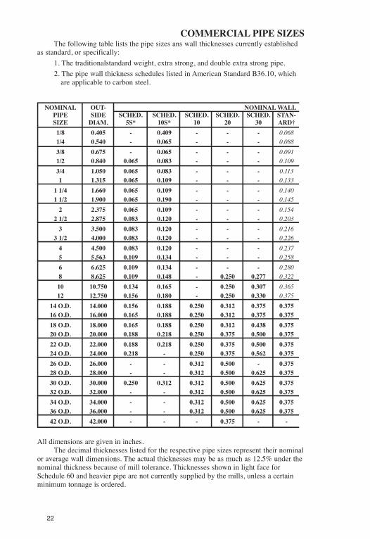
COMMERCIAL PIPE SIZESThe following table lists the pipe sizes ans wall thicknesses currently established
as standard, or specifically:1. The traditionalstandard weight, extra strong, and double extra strong pipe.2. The pipe wall thickness schedules listed in American Standard B36.10, which
are applicable to carbon steel.
NOMINAL OUT- NOMINALWALLPIPE SIDE SCHED. SCHED. SCHED. SCHED. SCHED. STAN-SIZE DIAM. 5S* 10S* 10 20 30 ARD†1/8 0.405 - 0.409 - - - 0.0681/4 0.540 - 0.065 - - - 0.0883/8 0.675 - 0.065 - - - 0.0911/2 0.840 0.065 0.083 - - - 0.1093/4 1.050 0.065 0.083 - - - 0.1131 1.315 0.065 0.109 - - - 0.1331 1/4 1.660 0.065 0.109 - - - 0.1401 1/2 1.900 0.065 0.190 - - - 0.1452 2.375 0.065 0.109 - - - 0.1542 1/2 2.875 0.083 0.120 - - - 0.2033 3.500 0.083 0.120 - - - 0.2163 1/2 4.000 0.083 0.120 - - - 0.2264 4.500 0.083 0.120 - - - 0.2375 5.563 0.109 0.134 - - - 0.2586 6.625 0.109 0.134 - - - 0.2808 8.625 0.109 0.148 - 0.250 0.277 0.32210 10.750 0.134 0.165 - 0.250 0.307 0.36512 12.750 0.156 0.180 - 0.250 0.330 0.375
14 O.D. 14.000 0.156 0.188 0.250 0.312 0.375 0.37516 O.D. 16.000 0.165 0.188 0.250 0.312 0.375 0.37518 O.D. 18.000 0.165 0.188 0.250 0.312 0.438 0.37520 O.D. 20.000 0.188 0.218 0.250 0.375 0.500 0.37522 O.D. 22.000 0.188 0.218 0.250 0.375 0.500 0.37524 O.D. 24.000 0.218 - 0.250 0.375 0.562 0.37526 O.D. 26.000 - - 0.312 0.500 - 0.37528 O.D. 28.000 - - 0.312 0.500 0.625 0.37530 O.D. 30.000 0.250 0.312 0.312 0.500 0.625 0.37532 O.D. 32.000 - - 0.312 0.500 0.625 0.37534 O.D. 34.000 - - 0.312 0.500 0.625 0.37536 O.D. 36.000 - - 0.312 0.500 0.625 0.37542 O.D. 42.000 - - - 0.375 - -
All dimensions are given in inches.The decimal thicknesses listed for the respective pipe sizes represent their nominal
or average wall dimensions. The actual thicknesses may be as much as 12.5% under thenominal thickness because of mill tolerance. Thicknesses shown in light face forSchedule 60 and heavier pipe are not currently supplied by the mills, unless a certainminimum tonnage is ordered.
22

23
ANDWALLTHICKNESSES
3. The pipe wall thickness schedules listed in American Standard B36.19, andASTM Specification A409, which are applicable only to corrosion resistant materials.(NOTE: Schedule 10S is also available in carbon steel in sizes 12” and smaller.
ASA-B36.10 and B36.19
THICKNESS FORSCHED. SCHED. EXTRA SCHED. SCHED. SCHED. SCHED. SCHED. XX40 60 STRONG‡ 80 100 120 140 160 STRONG0.068 - 0.095 0.095 - - - - -0.088 - 0.119 0.119 - - - - -0.091 - 0.126 0.126 - - - - -0.109 - 0.147 0.147 - - - 0.188 0.2940.113 - 0.154 0.154 - - - 0.219 0.3080.133 - 0.179 0.179 - - - 0.250 0.3580.140 - 0.191 0.191 - - - 0.250 0.3820.145 - 0.200 0.200 - - - 0.281 0.4000.154 - 0.218 0.218 - - - 0.344 0.4360.203 - 0.276 0.276 - - - 0.375 0.5520.216 - 0.300 0.300 - - - 0.438 0.6000.226 - 0.318 0.318 - - - - -0.237 - 0.337 0.337 - 0.438 - 0.531 0.6740.258 - 0.375 0.375 - 0.500 - 0.625 0.7500.280 - 0.432 0.432 - 0.562 - 0.719 0.8640.322 0.406 0.500 0.500 0.594 0.719 0.812 0.906 0.8750.365 0.500 0.500 0.594 0.719 0.844 1.000 1.125 1.0000.406 0.562 0.500 0.688 0.844 1.000 1.125 1.312 1.0000.438 0.594 0.500 0.750 0.938 1.094 1.250 1.406 -0.500 0.656 0.500 0.844 1.031 1.219 1.438 1.594 -0.562 0.750 0.500 0.938 1.156 1.375 1.562 1.781 -0.594 0.812 0.500 1.031 1.281 1.500 1.750 1.969 -- 0.875 0.500 1.125 1.375 1.625 1.875 2.125 -
0.688 0.969 0.500 1.218 1.531 1.812 2.062 2.344 -- - 0.500 - - - - - -- - 0.500 - - - - - -- - 0.500 - - - - - -
0.688 - 0.500 - - - - - -0.688 - 0.500 - - - - - -0.750 - 0.500 - - - - - -- - 0.500 - - - - - -
* Schedules 5S and 10S are available in corrosion resistant materials andSchedule 10S is also available in carbon steel.
† Thicknesses shown in italics are available also in stainless steel, under thedesignation Schedule 40S.
‡ Thicknesses shown in italics are available also in stainless steel, under thedesignation Schedule 80S.

24

25

26
PIPE AND WATER WEIGHT PER LINE FOOT
NOM.PIPE SIZE
STD. PIPE WATER XS PIPE WATER
1/2 .851 .132 1.088 .1013/4 1.131 .231 1.474 .1871 1.679 .374 2.172 .311
1 1/4 2.273 .648 2.997 .555
2 3.653 1.453 5.022 1.2782 1/2 5.794 2.073 7.662 1.835
3 7.580 3.200 10.250 2.8603 1/2 9.110 4.280 12.510 3.850
4 10.790 5.510 14.990 4.980
5 14.620 8.660 20.780 7.8806 18.980 12.510 28.580 11.2908 28.560 21.680 43.400 19.80010 40.500 34.100 54.700 32.30012 49.600 49.000 65.400 47.000
14 54.600 59.700 72.100 57.50016 62.600 79.100 82.800 76.50018 70.600 101.200 93.500 98.30020 78.600 126.00 104.100 122.800
24 94.600 183.800 125.500 179.90030 118.700 291.000 157.600 286.000
WEIGHT OF: WEIGHT OF:
WEIGHT PER FOOT OFSEAMLESS BRASS AND COPPER PIPE
NOM.PIPESIZE YELLOW RED YELLOW RED
BRASS BRASS COPPER BRASS BRASS COPPER
1/2 0.91 0.93 0.96 1.19 1.23 1.253/4 1.23 1.27 1.30 1.62 1.67 1.711 1.73 1.78 1.82 2.39 2.46 2.511 1/4 2.56 2.63 2.69 3.29 3.39 3.46
1 1/2 3.04 3.13 3.20 3.99 4.10 4.192 4.01 4.12 4.22 5.51 5.67 5.80

27
HEAT LOSSES FROM HORIZONTALBARE STEEL PIPE
(BTU per hour per linear foot at 70˚F room temperature)
NOM. STEAMPIPE HOT WATER 5 PSIGSIZE (180˚F) (20 PSIA)
1/2 60 963/4 73 1181 90 144
1 1/4 112 1791 1/2 126 202
2 155 2482 1/2 185 296
3 221 3553 1/2 244 401
4 279 448
TOTALTHERMAL EXPANSION OF PIPINGMATERIAL IN INCHES PER 100 FT. ABOVE 32˚F.
TEMPER- CARBON AND BRASSATURE CARBON MOLY CAST AND WROUGHT
˚F STEEL IRON COPPER BRONZE IRON
32 0 0 0 0 0100 0.5 0.5 0.8 0.8 0.5150 0.8 0.8 1.4 1.4 0.9200 1.2 1.2 2.0 2.0 1.3250 1.7 1.5 2.7 2.6 1.7
300 2.0 1.9 3.3 3.2 2.2350 2.5 2.3 4.0 3.9 2.6400 5.9 2.7 4.7 4.6 3.1450 3.4 3.1 5.3 5.2 3.6500 3.8 3.5 6.0 5.9 4.1
550 4.3 3.9 6.7 6.5 4.6600 4.8 4.4 7.4 7.2 5.2650 5.3 4.8 8.2 7.9 5.6700 5.9 5.3 9.0 8.5 6.1750 6.4 5.8 — — 6.7
800 7.0 6.3 — — 7.2850 7.4 — — — —900 8.0 — — — —950 8.5 — — — —1000 9.1 — — — —
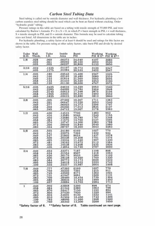
Carbon Steel Tubing DataSteel tubing is called out by outside diameter and wall thickness. For hydraulic plumbing a low
carbon seamless steel tubing should be used which can be bent an flared without cracking. Order“hydraulic grade” tubing.
Pressure ratings in this table are based on a tubing with tensile strength of 55,000 PSI, and werecalculated by Barlow’s formula: P = 2t x S ÷ O, in which P = burst strength in PSI, t = wall thickness,S = tensile strength in PSI, and O = outside diameter. This formula may be used to calculate tubingsizes not listed. All dimensions in the table are in inches.
For hydraulic plumbing, a safety factor of at least 6 should be used and ratings for this factor areshown in the table. For pressure rating at other safety factors, take burst PSI and divide by desiredsafety factor.
28
29
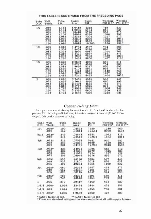
Copper Tubing DataBurst pressures are calculate by Barlow’s formula: P = 2t x S ÷ O in which P is burst
pressure PSI; t is tubing wall thickness; S is ultiate strength of material (32,000 PSI forcopper); O is outside diameter of tubing.

30
STAINLESS STEEL TUBING DATAStainless steel tubing is sometimes employed either to handle corrosive fuids, or higher
pressures. If assembled with flare-type fittings, great care must be used not to crack thetubing while flaring.
Pressure ratings are based on an ultimate strength of 75,000 PSI, typical of Types 302,303, 304, 309, 310, 316, 321, and 416. Types 202 and 440C have 100,000 PSI while Types410 and 430 have only 60,000 PSI ultimate.
In hydraulic systems a safety factor of at least 6 should be used if there is likely to be anyshock in the system. To calculate working pressure at any safety factor, take burst strengthand divide by desired safety factor.
Pressure ratings were calculated by Barlow’s formula: P = 2t x S ÷ O in which P is burstpressure in PS, t is tubing wall thickness, S is ultiate strength of tube material in PSI, O istube O.D. All dimensions are in inches.

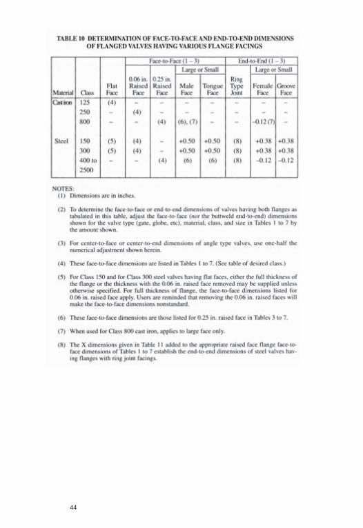
Face-to-Face and End-to EndDimensions of Ferrous Valves
AMERICAN NATIONAL STANDARD FACE-TO-FACE AND END-TO-ENDDIMENSIONS OF FERROUS VALVES ANSI B 16 10-1973
2.0 SIZE2.1 The size of the valves in the followingtables is indicated by the corresponding “normalvalve size”. Ventum valves have a sizedesignation using normal valve sizes for each endwith a normal seat port for a third size in betweenthe two end sizes.3.0 FACE-TO-FACE DIMENSIONS FOR
REGULAR STANDARD FACINGS*3.1 The face-to-face dimension for flangedvalves is the distance between the faces of theconnecting end flanges upon which the gasketsare actually compressed. This is sometimes called“contact surface-to-contact surface dimension”.
Dimensions for angle valves are center-to-face which is the distance between the centerlineof the port to the face of the connecting endflange upon which the gasket is actuallycompressed. This is sometimes called “center-to-contact surface dimension”.3.2 Flanges for cast-iron Class 125 valves areplain flat faced
The flanges of cast-iron Class 250 and steelClass 150 and 300 valves have 1/16 in. raisedfaces, which are included in the face-to-facedimensions. When Class 150 and 300 valves arerequired with plain faces, either the full thicknessof flange or the thickness with 1/16 in. raised faceremoved may be furnished unless otherwisespecified by the customer. Users are reminded thatremoving the 1/16 in. raised faces will make theface-to-face dimensions nonstandard.
The flanges of cast-iron Class 800 hydraulicand steel Class 400 and higher pressure valveshave 1/4 in. raised faces which are included in theface-to-face dimensions.4.0 END-TO-END DIMENSIONS **4.1 The end-to-end dimension for buttweldingend steel valves is the distance between the rootfaces of the welding lips.4.2 The end-to-end dimensions of bolted bonnetwelding end steel valves, except Class 150 gatevalves, Class 300 plug valves, Class 400 and 600round port full bore plug valves, and controlvalves are the same as the face-to-face dimensionsgiven for flanged end raised face steel valves.Pressure seal or flangelss bonnet welding endvalves may be made to these dimensions or haveshorter end-to-end dimensions as given in Tables4, 5, 6, and 7 at manufacturer’s option.
5.0 APPLYING OTHER STANDARD ORSPECIAL FACINGS*
5.1 The basic flange-edge to flange-edgedimension is the distance between the surfacesfrom which the basic flange thickness isdetermined.5.2 Ring Joints. The “X” dimensions given inTable 8 include the depth of grooves which areadded to the basic flange-edge to flange-edgedimensions to establish the face-to-facedimension. For approximate distances betweenflanges with ring joints when rings arecompressed, see dimension “S”, Table 8. Forcalculating the “laying length” of valves with ringjoints, the “S” dimension given in Table 8 must beadded.5.3 When it is desired to provide for a specialfacing on a flanged valve, the basic flange-edge toflange-edge dimensions must be determined andfacing heigth or depth added to it to establish thenew face-to-face.
When a special facing is applied to a valvehaving a plain face, or a 1/16 in. raised face, nodeductions are made from the dimensions in thetables. The additions for the special facing areapplied directly to the table dimensions. 1/16 in.raised faces are cut from the basic flangethicknesses and therefore, face-to-face and basicflange-edge to flange-edge is the same dimension.
When a special facing is applied to a valvehaving 1/4 in. raised face, the hight of the tworaised faces (1/2 in.) must be deducted from thedimensions given in the tables. The additions forthe special facing are added to this dimension(basic flange-edge to flange-edge), to determinethe new face-to-face dimension.6.0 TOLERANCE6.1 A plus or minus tolerance of 1/16 in. shallbe allowed on all face-to-face and end-to-enddimensions of valves 10 in. and smaller and a plusor minus tolerance of 1/8 in. for sizes 12 in. andlarger.6.2 The tolerances on center-to-face dimensionsof angel valves are one-half (1/2) of those listedin Par 6.1.
* See Fig 1.** See Fig 2.
31

32
* Example of Special Facing
A 10” Class 900 steel gate valve is desired with a recessed bevel 3/8”deep to accommodate a lens gasket.
From Table 5 Column 2 is found the face-to-face dimension of 33” for a10” Class 900 gate valve having regular stock facing of 1/4” raised face.
In accordance with Paragraph 5, the 1/4” is deducted from both flanges,resulting in a basic flange-edge to flange-edge dimension of 32 1/2”.
The 3/8” deep recessed bevel is added for each flange to the basic flange-edge to flange-edge dimension resulting in a new face-to-face dimension of33 1/4”.

33

34
35

36

37
38
39

40
41

42

43
44
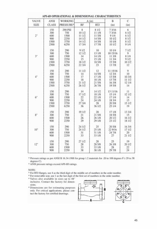
45

46

47
48
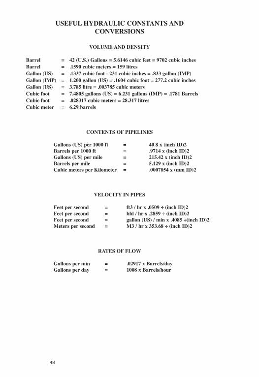
USEFUL HYDRAULIC CONSTANTS ANDCONVERSIONS
VOLUMEAND DENSITY
Barrel = 42 (U.S.) Gallons = 5.6146 cubic feet = 9702 cubic inchesBarrel = .1590 cubic meters = 159 litresGallon (US) = .1337 cubic foot - 231 cubic inches = .833 gallon (IMP)Gallon (IMP) = 1.200 gallon (US) = .1604 cubic foot = 277.2 cubic inchesGallon (US) = 3.785 litre = .003785 cubic metersCubic foot = 7.4805 gallons (US) = 6.231 gallons (IMP) = .1781 BarrelsCubic foot = .028317 cubic meters = 28.317 litresCubic meter = 6.29 barrels
CONTENTS OF PIPELINES
Gallons (US) per 1000 ft = 40.8 x (inch ID)2Barrels per 1000 ft = .9714 x (inch ID)2Gallons (US) per mile = 215.42 x (inch ID)2Barrels per mile = 5.129 x (inch ID)2Cubic meters per Kilometer = .0007854 x (mm ID)2
VELOCITY IN PIPES
Feet per second = ft3 / hr x .0509 ÷ (inch ID)2Feet per second = bbl / hr x .2859 ÷ (inch ID)2Feet per second = gallon (US) / min x .4085 ÷(inch ID)2Meters per second = M3 / hr x 353.68 ÷ (inch ID)2
RATES OF FLOW
Gallons per min = .02917 x Barrels/dayGallons per day = 1008 x Barrels/hour

UNIT CONVERSIONS
TEMPERATURE
˚C = (˚F-32) x 5/9
VOLUME
1 gal. (U.S.) = 128 fl. oz. (U.S.)= 231 cu. in.= 0.833 gal. (Brit.)
1 cu. ft. = 7.48 gal. (U.S.)
WEIGHT OFWATER
1 cu. ft. at 50˚F. weighs 62.41 lb.1 gal. at 50˚F. weighs 8.34 lb.1 cu. ft. of ice weighs 57.2 lb.Water is at its greatest density at 39.2˚F.1 cu. ft. at 39.2˚F. weighs 62.43 lb.
WEIGHT OF LIQUID
1 gal. (U.S.) = 8.34 lb. x sp. gr.1 cu. ft. = 62.3 lb x sp. gr.1 lb. = 0.12 U.S. gal. ÷ sp. gr.
= 0.016 cu. ft. ÷ sp. gr.
WORK
1 Btu (mean) = 778 ft. lb.= 0.293 watt hr.= 1/180 of heat required to change
temp of 1 lb. water from 32˚Fto 212˚F
1 hp-hr = 2545 Btu (mean)= 0.746 kwhr
1 Kwhr = 3413 Btu (mean)= 1.34 hp-hr
49

50

51

52
UNIT CONVERSIONS
FLOW
1 gpm = 0.134 cu. ft. per min.= 500 lb per hr. x sp. gr.
500 lb. per hr. = 1 gpm ÷ sp. gr.1 cu. ft. per min. (cfm) = 448.8 gal. per hr. (gph)
POWER
1 Btu per hr. = 0.293 watt= 12.96 ft. lb. per min.= 0.00039 hp
1 ton refrigeration (U.S.) = 288,000 Btu per 24 hr.=12,000 Btu per hr.= 200 Btu per min.= 83.33 lb. ice melted per hr.
from and at 32˚F1 hp = 550 ft. lb. per sec.
= 746 watt= 2545 Btu per hr.
1 boiler hp = 33,480 Btu per hr.= 34.5 lb. water evap. per hour.
from and at 212˚F= 9.8 kw.
1 kw. = 3413 Btu per hr.
MASS
1 lb. (avoir.) = 16 oz. (avoir.)= 7000 grain
1 ton (short) = 2000 lb.1 ton (long) = 2240 lb.
PRESSURE
1 lb. per sq. in. = 2.31 ft. water at 60˚F= 2.04 in. hg at 60˚F
1 ft. water at 60˚F = 0.433 lb. per sq. in.= 0.844 in. hg at 60˚F
1 in. Hg at 60˚F = 0.49 lb. per sq. in.= 1.13 ft. water at 60˚F
lb. per sq. in. = lb. per sq. in. gauge (psig)Absolute (psia) +14.7
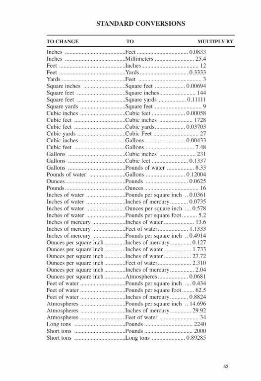
STANDARD CONVERSIONS
TO CHANGE TO MULTIPLY BY
Inches ........................................Feet .................................. 0.0833Inches ........................................Millimeters .......................... 25.4Feet ............................................Inches...................................... 12Feet ............................................Yards................................ 0.3333Yards ..........................................Feet .......................................... 3Square inches ............................Square feet .................... 0.00694Square feet ................................Square inches........................ 144Square feet ................................Square yards .................. 0.11111Square yards ..............................Square feet................................ 9Cubic inches ..............................Cubic feet ...................... 0.00058Cubic feet ..................................Cubic inches ...................... 1728Cubic feet ..................................Cubic yards.................... 0.03703Cubic yards ................................Cubic Feet .............................. 27Cubic inches ..............................Gallons .......................... 0.00433Cubic feet ..................................Gallons ................................ 7.48Gallons ......................................Cubic inches ........................ 231Gallons ......................................Cubic feet ........................ 0.1337Gallons ......................................Pounds of water .................. 8.33Pounds of water ........................Gallons .......................... 0.12004Ounces........................................Pounds ............................ 0.0625Pounds........................................Ounces .................................... 16Inches of water ..........................Pounds per square inch .. 0.0361Inches of water ..........................Inches of mercury............ 0.0735Inches of water ..........................Ounces per square inch .... 0.578Inches of water ..........................Pounds per square foot .......... 5.2Inches of mercury ......................Inches of water .................... 13.6Inches of mercury ......................Feet of water.................... 1.1333Inches of mercury ......................Pounds per square inch .. 0.4914Ounces per square inch ..............Inches of mercury.............. 0.127Ounces per square inch ..............Inches of water .................. 1.733Ounces per square inch ..............Inches of water .................. 27.72Ounces per square inch ..............Feet of water...................... 2.310Ounces per square inch ..............Inches of mercury................ 2.04Ounces per square inch ..............Atmospheres.................... 0.0681Feet of water ..............................Pounds per square inch .... 0.434Feet of water ..............................Pounds per square foot ........ 62.5Feet of water ..............................Inches of mercury............ 0.8824Atmospheres ..............................Pounds per square inch .. 14.696Atmospheres ..............................Inches of mercury.............. 29.92Atmospheres ..............................Feet of water .......................... 34Long tons ..................................Pounds ................................ 2240Short tons ..................................Pounds ................................ 2000Short tons ..................................Long tons ...................... 0.89285
53

54
55

56

57

58
ConversionFactors
Area
Rod
s2C
hain
s2Fe
et2
Yard
s2A
cres
Met
res2
Hec
tare
s16
010
43,5
604,
840
140
47.4
047
107,
639
2,47
110
,000
1
Volume(Flow)
US
Gal
lons
Imp.
Gal
lons
Cub
icM
etre
sPo
unds
(wat
er)
Cub
icFe
etA
cre
Inch
esA
cre
Feet
18.
33.1
337
110
.00
264.
122
01
2200
35.3
17.
486.
2462
.41
27,1
543,
630
11/
1232
5,85
043
,650
121
1m
illio
n3.
07

Pressure(Head)
Wat
erC
olum
nPS
IK
PAIn
ches
Feet
.145
14.
0.3
41
6.89
2.31
.433
2.98
121
PowerandEnergy
BTU
GJ
FT3
M3
H.P
.K
W3,
413
.003
61.
341
12,
545
.002
71
.746
950,
000
194
8.2
26.7
137
2.7
278
59

60
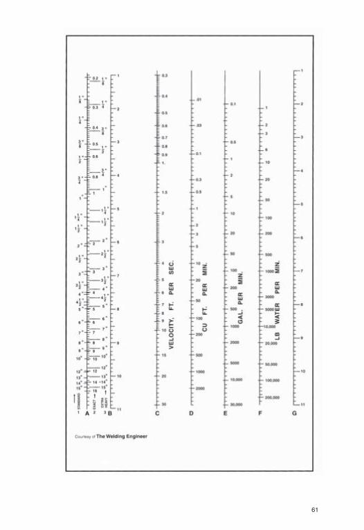
FLOW CONVERSION CHART
The accompanying chart provides fast answers to many problems thatmay confront the pipe fitter. Procedure for using the chart are as follows:
Note that there are three sets of figures shown in connection with theextreme left-hand column A. The column marked “1 in. standard” gives theinternal diameter of standard pipe (somewhat greater than 1 for 1 in.standard pipe). The column marked “2 exact” gives the exact diameter. Thecolumn marked “3 extra heavy” gives the internal diameter of extra heavypipe.
EXAMPLE: How much water is passing through a pipe having an I.D. ofexactly 1 in., the velocity of the water being 3 F.P.S.? To apply the chartto the problem locate 1 in. in column A over the word “exact” and run astraight line from the point through the 3 in column C. From theintersection of this line with column B, run a straight line horizontally tocolumn G. The intersection of this line at columns D, E and F gives thefollowing information:
Column D shows the cubic feet/minute flowing through the pipe; columnE shows the volume of flow in gallons/minute; column F gives the weightof the water in pounds/minute. (For liquids other than water, multiply thevalue of column F by the specific gravity of the liquid for accurate weightconversion.) See chart page 31.
If a quantity in columns D, E or F is known then velocity may bedetermined by reversing the procedure. Draw a horizontal line from theknown point to column G. From this intersection draw a line to the exactI.D. of the pipe in column A and extend this line to cross column C. Theintersection with column C gives the velocity in feet/second.
The chart can be used as a conversion chart to determine the number ofgallons in a certain number of cubic feet of liquid. The horizontal linealready drawn to determine answers in columns C and D will provide theanswer to the conversion in column E.
A little practice will prove this chart to be a real time-saver.
61

62
NOTES:

FORMULAS TO BE PROVIDED TO OPERATORSFOR CALCULATIONS
1. H.P. = RPM x Torque (ft/lbs) / 52522. Torque (ft/lbs) = (H.P. X 5252) / RPM3. H.P. = [ (Volts x Amps x 1.73 x Power factor (p.f.) x motor efficiency)
/1000] / .7464. Drive Sheave RPM x Drive Sheave Diameter = Motor Sheave RPM x
Motor Sheave Diameter
**ignoring belt slippage
5. Polish Rod RPM = Motor Sheave RPM x Motor Sheave DiameterDry Sheave Diameter
**ignoring belt slippage
FIND STROKES PER MINUTE (SPM)RPM divided by Gear Ratio divided by Big Sheave multiplied by SmallSheave equals Strokes per Minute.
FIND SMALL SHEAVESPM multiplied by Gear Ratio multiplied by Big Sheave divided by RPMequals Small Sheave.
FIND BIG SHEAVERPM divided by Gear Ratio divided by SPM multiplied by Small Sheaveequals Big Sheave.
FIND BELT SIZEBig Sheave plus Little Sheave multiplied by 1.57 plus 2 times the distancefrom shaft centre to shaft centre equals Belt Size.
**Estimate Only
63

64
65

66

67

68
NOTES:

69

70

71

72
73

74

75

76

77
78
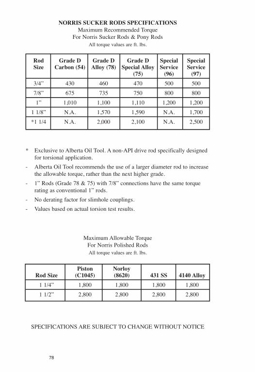
NORRIS SUCKER RODS SPECIFICATIONSMaximum Recommended Torque
For Norris Sucker Rods & Pony RodsAll torque values are ft. lbs.
Rod Grade D Grade D Grade D Special SpecialSize Carbon (54) Alloy (78) Special Alloy Service Service
(75) (96) (97)3/4” 430 460 470 500 5007/8” 675 735 750 800 8001” 1,010 1,100 1,110 1,200 1,200
1 1/8” N.A. 1,570 1,590 N.A. 1,700*1 1/4 N.A. 2,000 2,100 N.A. 2,500
* Exclusive to Alberta Oil Tool. A non-API drive rod specifically designedfor torsional application.
- Alberta Oil Tool recommends the use of a larger diameter rod to increasethe allowable torque, rather than the next higher grade.
- 1” Rods (Grade 78 & 75) with 7/8” connections have the same torquerating as conventional 1” rods.
- No derating factor for slimhole couplings.- Values based on actual torsion test results.
Maximum Allowable TorqueFor Norris Polished RodsAll torque values are ft. lbs.
Piston NorloyRod Size (C1045) (8620) 431 SS 4140 Alloy1 1/4” 1,800 1,800 1,800 1,8001 1/2” 2,800 2,800 2,800 2,800
SPECIFICATIONS ARE SUBJECT TO CHANGE WITHOUT NOTICE
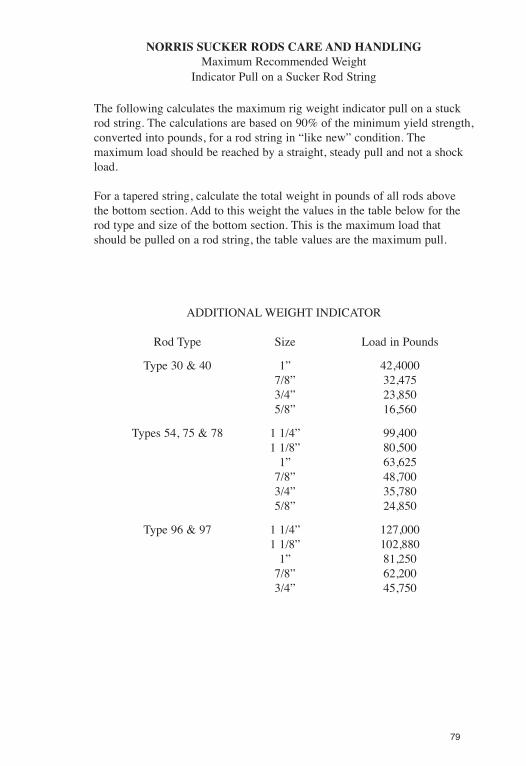
NORRIS SUCKER RODS CARE AND HANDLINGMaximum Recommended Weight
Indicator Pull on a Sucker Rod String
The following calculates the maximum rig weight indicator pull on a stuckrod string. The calculations are based on 90% of the minimum yield strength,converted into pounds, for a rod string in “like new” condition. Themaximum load should be reached by a straight, steady pull and not a shockload.
For a tapered string, calculate the total weight in pounds of all rods abovethe bottom section. Add to this weight the values in the table below for therod type and size of the bottom section. This is the maximum load thatshould be pulled on a rod string, the table values are the maximum pull.
ADDITIONAL WEIGHT INDICATOR
Rod Type Size Load in Pounds
Type 30 & 40 1” 42,40007/8” 32,4753/4” 23,8505/8” 16,560
Types 54, 75 & 78 1 1/4” 99,4001 1/8” 80,500
1” 63,6257/8” 48,7003/4” 35,7805/8” 24,850
Type 96 & 97 1 1/4” 127,0001 1/8” 102,880
1” 81,2507/8” 62,2003/4” 45,750
79

80

81

Bas
edon
API
Spec
ifica
tion
11B
Yield
Tensile
Color
strength
strength
Elongation
Reduction
Brinel
Heat
Manufacturer
Type
Code
1,000psi
1,000psi
8",%
ofarea,%
hardness
Treatment
SUCKERRODCOMPARISONCHART
MECHANICALPROPERTIES(E.&O.E.)
APIGRADEC
CarbonSteel
Axelson
S-60
White
90/105
100/115
13-20
55-65
207-235
Quenched&Tempered
LTV
1White
60/75
90/105
18-25
55-66
187-217
Normalized
National-Oilwell
CWhite
60/75
90/105
19-24
53-68
185-217
HeatTreated
Norris
30
White
68/80
100/110
18-23
45-65
210-230
Normalized
Trico
C11
White
60/75
90/115
18-23
50-65
190-205
Normalized
Tenaris
CWhite
60
90/115
Normalized&Tempered
APIGRADEK
NickelMolyAlloy
Axelson
S-59
Blue
90/105
100/115
13-20
55-65
207-235
Quenched&Tempered
LTV
5Blue
75/85
88/105
16-25
60-70
182-217
Normalized&Tempered
National-Oilwell
KBlue
70/85
85/105
16-25
60-70
182-217
HeatTreated
Norris
40
Blue
70/80
90/100
14-18
60-70
175-207
Normalized&Tempered
Trico
K65
Blue
75/85
90/110
16Mn
60-70
180-220
Normalized&Tempered
Tenaris
KBlue
60
90/115
Normalized
NOTES:
1.InformationSources
APISpecification11B.24thEdition
2.ColorcodesaccordingtoAPISpecification11B,24thEdition
LTVSuckerRodBrochureP111,10M-8/84
GradeC–White
National-OilwellSuckerRodBulletin155,Rev.111,5/90SL
GradeK–Blue
NorrisSuckerRodBrochure,Dec.1,1989
GradeD–CarbonSteel,Brown
TricoSuckerRodBrochure,TB-170/2-86
–Chrome-Moly,Yellow
WorldOilSuckerRodTables,March1987
–Special,Orange
MorMD=Modified
MN=Minimum
Mx=Maximum
T=Typical
82
Bas
edon
API
Spec
ifica
tion
11B
Yield
Tensile
Color
strength
strength
Elongation
Reduction
Brinel
Heat
Manufacturer
Type
Code
1,000psi
1,000psi
8",%
ofarea,%
hardness
Treatment
SUCKERRODCOMPARISONCHART
MECHANICALPROPERTIES(E.&O.E.)
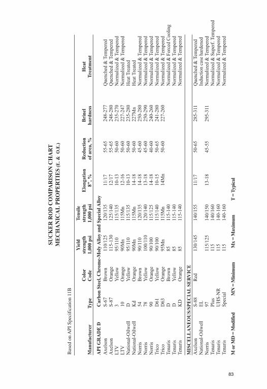
APIGRADED
CarbonSteel,Chrome-MolyAlloyandSpecialAlloy
Axelson
S-67
Brown
110/125
120/135
11/17
55-65
248-277
Quenched&Tempered
Axelson
S-87
Orange
115-130
125/140
12/17
55-65
248-280
Quenched&Tempered
LTV
3Yellow
95/110
115/135
10-13
50-60
235-270
Normalized&Tempered
LTV
10
Orange
90Mn
115Mn
12-16
50-60
227-247
Normalized&Tempered
National-Oilwell
DYellow
95/110
115/135
10-13
50-60
235-280
HeatTreated
National-Oilwell
Kd
Orange
90Mn
115Mn
14-18
50-60
227Mn
HeatTreated
Norris
54
Brown
90/110
120/135
14-18
45-60
250-280
Normalized&Tempered
Norris
78
Yellow
100/110
120/140
13-18
45-60
250-290
Normalized&Tempered
Norris
90
Orange
90/100
115/125
14-18
40-60
240-260
Normalized&Tempered
Trico
D61
Yellow
90/100
115/140
10-15
50-65
241-280
Normalized&Tempered
Trico
D63
Orange
95Mn
115Mn
14Mn
50-60
227-260
Normalized&Tempered
Tenaris
DBrown
85
115-140
Normalized&ForcedCooling
Tenaris
DYellow
85
115-140
Normalized&Tempered
Tenaris
KD
Orange
85
115-140
Normalized&Tempered
MorMD=Modified
MN=Minimum
Mx=Maximum
T=Typical
MISCELLANEOUS/SPECIALSERVICE
Axelson
S-88
Red
130/145
140/155
11/17
50-65
285-311
Quenched&Tempered
National-Oilwell
EL
Inductioncasehardened
Norris
97
115/125
140/150
13-18
45-55
295-311
Normalized&Tempered
Tenaris
Plus
115
140/160
Normalized&Superf.Tempered
Tenaris
UHS-NR
115
140-160
Normalized&Tempered
Tenaris
Special
115
140-160
Normalized&Tempered
83

Bas
edon
API
Spec
ifica
tion
11B
Steel
%%
%%
%%
%%
%
Manufacturer
TypeType
CarbonMang.
Phos.
Sulpher
Silicon
Nickel
ChromiumMoly
Other
SUCKERRODCOMPARISONCHART
CHEMICALANALYSES(E.&O.E.)
APIGRADED
CarbonSteel
Axelson
S-60
1029Md
.22-.29
1.00-1.32
.025Mx
.04Mx
.15-.30
.15Mx
.20Mx
.05Mx
.35CuMn
LTV
11536
.30-.37
1.20-1.50
.04Mx
.05Mx
.15-.30
National-Oilwell
C1536
.33-.43
1.20-1.65
.04Mx
.05Mx
.15-.30
Norris
30
C-1536M
.34-.39
1.15-1.45
.04Mx
.04Mx
.20-.30
.35Mx
.30Mx
.06Mx
.04-.07Va,.35MxCu
Trico
C11
1536
.30-.37
1.20-1.50
.04Mx
.05Mx
.20-.30
Tenaris
C1530M
.31-.36
1.40-1.60
.025Mx
.025Mx
.25-.40
.15Mx
.20Mx
.05Mx
MorMD=Modified
MN=Minimum
Mx=Maximum
T=Typical
APIGRADEK
NickelMolyAlloy
Axelson
S-59
46XX
.14-.21
.55-.75
.025Mx
.035MX
.15-.35
1.65-2.00
.20-.30
LTV
54623Md
.20-.25
.75-1.00
.04Mx
.04Mx
.20-.35
1.65-2.00
.20-.30
National-Oilwell
K4621Md
.20-.25
.75-1.00
.03Mx
.04Mx
.15-.30
1.65-2.00
.03Mx
.20-.30
Norris
40
A-4621M
.20-.25
.60-.80
.035Mx
.035MX
.20-.30
1.65-2.00
.20MX
.15-.25
.04-.07VA,.35MxCU
Trico
K65
4623
.20-.25
.75-1.00
.04Mx
.04Mx
.15-.30
1.65-2.00
.20-.30
Tenaris
K4621M
.18-.25
.70-1.00
.025Mx
.025Mx
.25-.30
1.65-2.00
0.2Mx
.20-.30
*Generallymanufacturedfrom,butnotrestrictedtoAISI1536
**Anycompositionwhichcanbeeffectivelyheattreatedtotheminimumultimatetensilestrength
NOTES:
1.InformationSources
APISpecification11B.24thEdition
2.ColorcodesaccordingtoAPISpecification11B,24thEdition
LTVSuckerRodBrochureP111,10M-8/84
GradeC–White
National-OilwellSuckerRodBulletin155,Rev.111,5/90SL
GradeK–Blue
NorrisSuckerRodBrochure,Dec.1,1989
GradeD–CarbonSteel,Brown
TricoSuckerRodBrochure,TB-170/2-86
–Chrome-Moly,Yellow
WorldOilSuckerRodTables,March1987
–Special,Orange
84

MorMD=Modified
MN=Minimum
Mx=Maximum
T=Typical
MISCELLANEOUS/SPECIALSERVICE
Axelson
S-88
3130Md
.22-.29
.71-1.00
.025Mx
.35Mx
.15-.35
.70-1.00
.41-.65
.05Mx
.35CuMx
National-Oilwell
EL
Special
.35-.39
.75-.95
.025Mx
.035Mx
.15-.35
1.45-1.75.80-1.00
.20-.30
.03-.05Va
Norris
97
A-4340Sp
.38-.43
.70-.90
.035Mx
.040Mx
.20-.35
1.65-2.00.70-.90
.20-.30
.04-.07Va,.35MxCu
Tenaris
Plus
1530M
.31-.36
1.40-1.60
.25Mx
.25Mx
.25-.40
.15Mx
.20Mx
.05Mx
Tenaris
UHS-NR4330M
.30-.35
.70-.95
.25Mx
.25Mx
.15-.35
1.65-2.00.80-1.00
.20-.30
Tenaris
Special4138M
.38-.43
1.10-1.40
.25Mx
.25Mx
.20-.40
.30Mx
.60-.80
.25-.35
Bas
edon
API
Spec
ifica
tion
11B
Steel
%%
%%
%%
%%
%
Manufacturer
TypeType
CarbonMang.
Phos.
Sulpher
Silicon
Nickel
ChromiumMoly
Other
SUCKERRODCOMPARISONCHART
CHEMICALANALYSES(E.&O.E.)
APIGRADED
CarbonSteel,Chrome-MolyAlloyandSpecialAlloy
Axelson
S-67
1029Md
.22-.29
1.00-1.32
.025Mx
.04Mx
.15-.30
.15Mx
.20Mx
.05Mx
.35CuMx
Axelson
S-87
3130Md
.22-.29
.71-1.00
.025Mx
.035Mx
.15-.35
.70-1.00
.41-.65
.05Mx
.35CuMx
LTV
34142H
.39-.46
.65-1.00
.04Mx
.04Mx
.50-.30
.75-1.20
.20-.30
LTV
10
Special
.17-.22
.80-1.00
.35Mx
.04Mx
.15-.30
.90-1.50
.80-1.05
.22-.30
.02-.03Va,.40-.60Cu
National-Oilwell
D4142Md
.39-.46
.65-1.00
.04Mx
.05Mx
.50-.35
.75-1.20
.15-.30
National-Oilwell
Kd
Special
.18-.25
.60-1.05
.04Mx
.04Mx
.15-.35
.90-1.50
.60-1.05
.20-.30
Norris
54
C-1541Vm
.40-.45
1.35-1.55
.025Mx
.030Mx
.20-.30
.35Mx
.30Mx
.06Mx
.07-.08Va,.35MxCu
Norris
78
A-4142M
.40-.45
.80-1.00
.035Mx
.035Mx
.20-.30
.45Mx
.90-1.00
.15-.25
.02-.03Cb,.35MxCu
Norris
90
A-4320M
.18-.23
.80-1.00
.025Mx
.025Mx
.20-.30
1.15-1.50
.70-.90
.20-.30
.05-.07VA,35MxCu
Trico
D61
4142
.40-.45
.75-1.00
.04Mx
.04Mx
.20-.30
.80-1.10
.15-.25
Trico
D63
Special
.22-.28
.65-.95
.04Mx
.04Mx
.15-.30
1.20-1.50
.60-.90
.20-.30
.40-.70Cu
Tenaris
D-CAR1530M
.31-.36
1.40-1.60
.25Mx
.25Mx
.25-.40
.15Mx
.20Mx
.05Mx
Tenaris
D-AL4142M
.40-.45
.75-1.00
.25Mx
.25Mx
.15-.35
.25Mx
.80-1.10
.15-.25
Tenaris
K-DE4320M
.18-.24
.80-1.00
.25Mx
.25Mx
.15-.35
1.15-1.50
.70-.90
.20-.30
*Generallymanufacturedfrom,butnotrestrictedtoAISI1536
**Anycompositionwhichcanbeeffectivelyheattreatedtotheminimumultimatetensilestrength
85

86

87
88
89

90

91
92
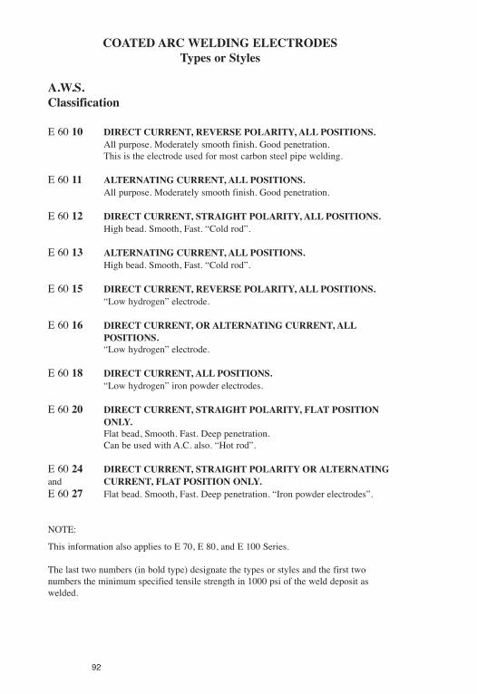
COATED ARCWELDING ELECTRODESTypes or Styles
A.W.S.Classification
E 60 10 DIRECT CURRENT, REVERSE POLARITY, ALL POSITIONS.All purpose. Moderately smooth finish. Good penetration.This is the electrode used for most carbon steel pipe welding.
E 60 11 ALTERNATING CURRENT, ALL POSITIONS.All purpose. Moderately smooth finish. Good penetration.
E 60 12 DIRECT CURRENT, STRAIGHT POLARITY, ALL POSITIONS.High bead. Smooth, Fast. “Cold rod”.
E 60 13 ALTERNATING CURRENT, ALL POSITIONS.High bead. Smooth, Fast. “Cold rod”.
E 60 15 DIRECT CURRENT, REVERSE POLARITY, ALL POSITIONS.“Low hydrogen” electrode.
E 60 16 DIRECT CURRENT, OR ALTERNATING CURRENT, ALLPOSITIONS.“Low hydrogen” electrode.
E 60 18 DIRECT CURRENT, ALL POSITIONS.“Low hydrogen” iron powder electrodes.
E 60 20 DIRECT CURRENT, STRAIGHT POLARITY, FLAT POSITIONONLY.Flat bead, Smooth. Fast. Deep penetration.Can be used with A.C. also. “Hot rod”.
E 60 24 DIRECT CURRENT, STRAIGHT POLARITY OR ALTERNATINGand CURRENT, FLAT POSITION ONLY.E 60 27 Flat bead. Smooth, Fast. Deep penetration. “Iron powder electrodes”.
NOTE:
This information also applies to E 70, E 80, and E 100 Series.
The last two numbers (in bold type) designate the types or styles and the first twonumbers the minimum specified tensile strength in 1000 psi of the weld deposit aswelded.
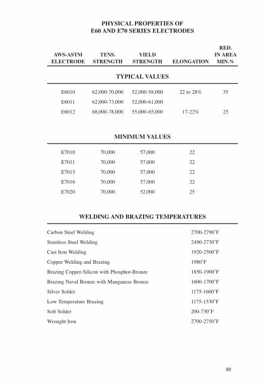
PHYSICAL PROPERTIES OFE60 AND E70 SERIES ELECTRODES
RED.AWS-ASTM TENS. YIELD IN AREAELECTRODE STRENGTH STRENGTH ELONGATION MIN.%
TYPICALVALUES
E6010 62,000-70,000 52,000-58,000 22 to 28% 35
E6011 62,000-73,000 52,000-61,000
E6012 68,000-78,000 55,000-65,000 17-22% 25
MINIMUM VALUES
E7010 70,000 57,000 22
E7011 70,000 57,000 22
E7015 70,000 57,000 22
E7016 70,000 57,000 22
E7020 70,000 52,000 25
WELDING AND BRAZING TEMPERATURES
Carbon Steel Welding 2700-2790˚F
Stainless Steel Welding 2490-2730˚F
Cast Iron Welding 1920-2500˚F
Copper Welding and Brazing 1980˚F
Brazing Copper-Silicon with Phosphor-Bronze 1850-1900˚F
Brazing Naval Bronze with Manganese Bronze 1600-1700˚F
Silver Solder 1175-1600˚F
Low Temperature Brazing 1175-1530˚F
Soft Solder 200-730˚F
Wrought Iron 2700-2750˚F
93

94
95

96
97

98
99

100
101

102

103
104
105

106

107

108

109
110

111
WEIGHTS OFMETALS
CHEMICAL WEIGHT, IN POUNDS WEIGHT, IN POUNDSMATERIAL SYMBOL PER CUBIC INCH PER CUBIC FOOT
Aluminum Al .093 160Antimony Sb .2422 418Brass — .303 524Bronze — .320 552Chromium Cr .2348 406
Copper Cu .323 558Gold Au .6975 1205Iron (cast) Fe .260 450Iron (wrought) Fe .2834 490Lead Pb .4105 710
Manganese Mn .2679 463Mercury Hg .491 849Molybdenum Mo .309 534Monel — .318 550Platinum Pt .818 1413
Steel (mild) — .2816 490Steel (stainless) — .277 484Tin Sn .265 459Titanium Ti .1278 221Zinc Zn .258 446
COLORS AND APPROXIMATE TEMPERATUREFOR CARBON STEEL
Black Red ..................................................................................................................990˚FDark Blood Red........................................................................................................1050Dark Cherry Red ......................................................................................................1175Medium Cherry Red ................................................................................................1250Full Cherry Red ......................................................................................................1375Light Cherry, Scaling................................................................................................1550Salmon, Free Scaling................................................................................................1650Light Salmon ............................................................................................................1725Yellow ......................................................................................................................1825Light Yellow ............................................................................................................1975White ........................................................................................................................2220

112

113
114
WIRE ROPE
Wire rope has largely displaced manila rope in hauling andhoisting heavy loads. As with manila rope, the care of wire rope hasa direct bearing on its safe use.
Some of the reasons responsible for the use of wire rope in placeof manila are:
1. Greater strength for equal diameter and weight.
2. Equal strength either wet or dry.
3. Constant length regardless of weather conditions.
4. Greater uniformity in strength throughout.
5. Greater number of types for various uses.
6. Lower cost per unit of strength.
7. Greater durability, with equal care in use.
Strength of wire ropes vary, depending on the material fromwhich the individual strands are made and the method used informing the cable, ranging from between 30 and 100 tons per squareinch.
Primarily, there are 3 classes of wire rope: (1) iron, (2) cast steel,and (3) plow steel.
Iron wire is soft and of low tensile strength, around 30 to 40 tonsper square inch. Commonly used for drum type elevator cables andto some extent for derrick guys; being replaced by low-carbon steelwire in these uses.
Cast steel may have a tensile strength up to 90 tons per squareinch and because of its greater strength is generally used for hoistingpurposes. To check quickly whether a piece of wire is iron or steel,bend it. Iron will bend easily and take a long time to regain itsoriginal shape, while cast steel will be harder to bend and will snapback to its original shape very quickly.

Plow steel wire rope is made from high grade, open hearthfurnace steel and has an average tensile strength of 110 tons persquare inch. This is the best and safest wire rope for cranes,derricks, dredges and slings or straps for heavy loads.
Lubrication —Wire Rope
All wire rope, whether used indoors or out, should in the courseof regular work be considered as a group of moving wiresconstantly rubbing against one another, with friction resulting. Thisfriction causes incessant wear on the moving parts of the wire ropeor cable and will shorten its life very rapidly unless lubricants areused to overcome the friction.
Cable or cable wire shoud be treated at regular intervals with alubricant to prevent rusting and to overcome the friction.Lubricating intervals depend on the types and the amount of workencountered. Under average conditions, of worked stadily onequipment, wire rope or cable will require lubrication once every 3weeks. Where heavy abrasive dusts exist, more frequent lubricationis in order. Rusty ropes may break without warning.
Sheaves
The life of wire rope or cable is directly affected by thecondition and size of the sheaves over which it is used. Sheavesshould be at least 16 x the diameter of the rope or cable that is usedover them. In passing over a sheave, the inside porion of the cable,which is against the sheave, is shortened and compression isdeveloped in that section of the cable. The outside portion (awayfron the sheave) is lengthened or stretched, causing tension in thatsection. These compressive and tensional
115

stresses combine to create bending stresses which increase rapidlyas the diameter of the sheaves decrease. As these bending stressescause much undue wear and directly shorten the safe working life ofthe rope or cable, the ratio mention between sheaves and ropeshould be maintained.
New wire rope may be badly injured and will not work properlyin the sheaves that have become worn or in theich the grooves havebecome irregular in shape. When sheaves are worn or damaged, it ismore economical to renew the sheaves rather than to allowexcessive wear on the cable.
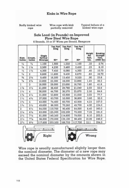
One cause of very sever wear in wire rope or cables is reversebending, which will shorten the life of the rope by approximately1/2. Reverse bending refers to the bending of a cable or rope oversheaves, first in one direction then in another.
Another cause of severe rope wear is twisting of the fall rope.When the fall rope is twisted and a hoist is made, the wear producedis equal to more than that resulting from weeks of normal use. Theman in charge of lifting operations should guard against twisting ofthe fall rope and should anot allow a lift to be made if the fall ropeis twisted.
Handling Cable or Wire Rope
Cable or wire rope cannot and must not be coiled or uncoiledlike manila rope. Cable or wire rope must be taken off the reel in astreaight line, avoiding kinking. The reel may be mounted on aheavy pipe or roller to facilitate unwinding. If space is limited, thecable as it comes off the reel may be layed out in a figure 8, afterwhich it can be reeved into the line for which it is intended.
116

117
118
119

120

121

122
NOTES:

USEFUL DEFINITIONS
ALLOY STEEL: A steel which owes its distinctive properties toelements other than carbon.
AREA OF A CIRCLE: The measurement of the surface within acircle. To find the area of a circle, multiply the product of theradius times the radius by Pi (3.142). Commonly written A =πr2.
BRAZE WELD OR BRAZING: A process of joining metals using anonferrous filler metal or alloy, the melting point of which ishigher than 800˚F but lower than that of the metals to bejoined.
BUTT WELD: A circumferential weld in pipe fusing theabutting pipe walls completely from inside wall to outsidewall.
CARBON STEEL: A steel which owes its distinctive propertieschiefly to the various percentages of carbon (as distinguishedfrom the other elements) which it contains.
CIRCUMFERENCE OF A CIRCLE: The measurement around theperimeter of a circle. To find the circumference, multiply Pi(3.142) by the diameter. (Commonly written as πd).
COEFFICIENT OF EXPANSION: A number indicating the degreeof expansion or contraction of a substance
The coefficient of expansion is not constant and varies withchanges in temperature. For linear expansion it is expressedas the change in length of one unit of length of a substancehaving one degree rise in temperature.
CORROSION: The gradual destruction or alteration of a metalor alloy caused by direct chemical attack or byelectrochemical reaction.
CREEP: The plastic flow of pipe within a system; thepermanent set in metal caused by stresses at hightemperatures. Generally associated with a time rate ofdeformation.
123

124
USEFUL DEFINITIONS
DIAMETER OF A CIRCLE: A staight line drawn down throughthe center of a circle from one extreme edge to the other.Equal to twice the radius.
DUCTILITY: The property of elongation, above the elasticlimit, but under the tensile strength.
A measure of ductility is the percentage of elongation of thefractured piece over its original length.
ELASTIC LIMIT: The greatest stress which a material canwithstand without a permanent deformation after the relief ofstress.
EROSION: The gradual destruction of metal or other materialby the abrasive action of liquids, gases, solids or mixturesthereof.
RADIUS OF A CIRCLE: A straight line drawn from the center tothe extreme edge of a circle.
SOCKET FITTING: A fitting used to join pipe in which the pipeis inserted into the fitting. A fillet weld is then made aroundthe edge of the fitting and the outside wall of the pipe.
SOLDERING: A method of joining metals using fusable alloys,usually tin and lead, having melting points under 700˚F
STRAIN: Change of shape or size of a body produced by theaction of a stress.
STRESS: The intensity of the internal, distributed forces whichresist a change in the form of a body. When external forcesact on a body they are resisted by reactions within the bodywhich are termed stresses.
DEFINITIONS (Continued)
TENSILE STRENGTH: One that resists a force tending to pull abody apart.
COMPRESSIVE STRESS: One that resists a force tending tocrush a body.
TORSIONAL STRESS: One that resists forces tending to twist abody.
TENSILE STRENGTH: The maximum tensile stress which amaterial will develop. The tensile strength is usuallyconsidered to be the load in pounds per square inch at whicha test specimen ruptures.
TURBULENSE: Any deviation from parallel flow in a pipe dueto rough inner walls, obstructions or directional changes.
VELOCITY: Time rate of motion in a given direction andsense, usually expressed in feet per second.
VOLUME OF A PIPE: The measurement of the space withing thewalls of the pipe. To find the volume of a pipe, multiply thelength (or height) of the pipe by the product of the insideradius times the inside radius by Pi (3.142). Commonlywritten V = hπr2.
WELDING: A process of joining metals by heating until theyare fused together, or by heating and applying pressure untilthere is a plastic joining action. Filler metal may or may notbe used.
YIELD STRENGTH: The stress at which a material exhibits aspecified limiting permanent set.
125

126
LIST OFABBREVIATIONS
Abbreviations conform to the practice of the AmericanStandard Abbreviations for Scientific and Engineering terms,ASA Z10.1.
abs ......................................................................................................AbsoluteAGA........................................................................American Gas AssociationAISI..............................................................American Iron and Steel InstituteAmer Std ............................................................................American StandardAPI ......................................................................American Petroleum InstitueASA ..............................................................American Standards AssociationASHVE ....................American Society of Heating and Ventilating EngineersASME..........................................American Society of Mechanical EngineersASTM ................................................American Society for Testing MaterialsAWWA ....................................................American Water Works AssociationB & S ..........................................Bell and spigot or Brown & Sharpe (gauge)bbl ............................................................................................................BarrelBtu ....................................................................................British thermal unitsC ......................................................................................................Centigradecfm..................................................................................Cubic feet per minutecfs....................................................................................Cubic feet per secondCI ........................................................................................................Cast ironCS ......................................................................................................Cast steelComp ..............................................................................................CompanionC to F ..........................................................................................Center to face˚C........................................................................................Degrees Centigrade˚F ..........................................................................................Degrees Farenheitdiam ....................................................................................................Diameterdwg ......................................................................................................Drawingex-hy ..............................................................................................Extra-heavyF&D ......................................................................................Faced and drilledF..........................................................................................................FarenheitF to F ..............................................................................................Face to faceflg ..........................................................................................Flange or flanges

LIST OFABBREVIATIONS (Continued)
flgd........................................................................................................Flangedg..................................................................................................Gage or gaugehex ....................................................................................................Hexagonalhg..........................................................................................................mercuryIBBM......................................................Iron body bronze (or brass) mountedID ..............................................................................................Inside diameterkw ....................................................................................................Kilowatt(s)MI ..............................................................................................Malleable ironmax....................................................................................................Maximummin ....................................................................................................Minimummtd ......................................................................................................MountedMSS ..............................................Manufacturers Standardization Society (of
Valve and Fittings Industry)NEWWA ............................................New England Water Works AssociationNPS ................................Nominal pipe size (formerly IPS for iron pipe size)OD..........................................................................................Outside diameterOS&Y..........................................................................Outside screw and yokeOWG ..........................................................................................................psigPounds per square inch, gagered ......................................................................................................Reducingsch or sched ........................................................................................Schedulescd ......................................................................................................ScrewsedSF..................................................................................................SemifinishedSpec ..............................................................................................SpecificationSSP................................................................................Steam service pressureSSU ........................................................................Seconds Saybolt UniversalStd........................................................................................................StandardTrans ..........................................................................................TransportationWOG ......................................................................Water, oil, gas (see OWG)WWP ..........................................................................Working water pressureXS ..................................................................................................Extra strongXXS ..................................................................................Double extra strong
127

128
NOTES:

WELDING FITTINGS
129

DIMENSIONS
130

WELDING FITTINGS
131

132

133

134

135
136

137
138
139

140

ANSI TO PN PRESSURE CHART
ANSI RATING PN RATING150 20300 50400 68600 100900 1501500 2502500 420
142

TABLES 2PRESSURE - TEMPERATURE RATINGS FORGROUPS 1.1 THROUGH 3.16 MATERIALS
143

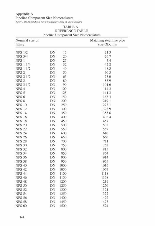
Appendix APipeline Component Size NomenclatureNote: This Appendix is not a mandatory part of this Standard
TABLE A1REFERENCE TABLE
Pipeline Component Size NomenclatureNominal size of Matching steel line pipefitting size OD, mm
NPS 1/2 DN 15 21.3NPS 3/4 DN 20 26.7NPS 1 DN 25 3.4NPS 1 1/4 DN 32 42.2NPS 1 1/2 DN 40 48.3NPS 2 DN 50 60.3NPS 2 1/2 DN 65 73.0NPS 3 DN 80 88.9NPS 3 1/2 DN 90 101.6NPS 4 DN 100 114.3NPS 5 DN 125 141.3NPS 6 DN 150 168.3NPS 8 DN 200 219.1NPS 10 DN 250 273.1NPS 12 DN 300 323.9NPS 14 DN 350 355.6NPS 16 DN 400 406.4NPS 18 DN 450 457NPS 20 DN 500 508NPS 22 DN 550 559NPS 24 DN 600 610NPS 26 DN 650 660NPS 28 DN 700 711NPS 30 DN 750 762NPS 32 DN 800 813NPS 34 DN 850 864NPS 36 DN 900 914NPS 38 DN 950 965NPS 40 DN 1000 1016NPS 42 DN 1050 1067NPS 44 DN 1100 1118NPS 46 DN 1150 1168NPS 48 DN 1200 1219NPS 50 DN 1250 1270NPS 52 DN 1300 1321NPS 54 DN 1350 1372NPS 56 DN 1400 1422NPS 58 DN 1450 1473NPS 60 DN 1500 1524
144
Appendix BNominal Pressure Class NomenclatureNote: This Appendix in not a mandatory part of this Standard
TABLE B1REFERENCE TABLE
Nominal Pressure Class Nomenclature
ANSI class designation Nominal pressure class150 PN 20300 PN 50400 PN 68600 PN 100900 PN 1501500 PN 2502500 PN 420
Notes:(1) ANSI class designations are designations given to flanges to indicate themanufacturing dimensions and maximum allowable non-shock workingpressure considering the material utilized and the operating temperature.(2) “PN” means “pressure nominal” and the PN system of nominal pressureclass designation is contained in standards prepared by the InternationalOrganization for Standardization (ISO). The numerical part of thedesignation approximates the maximum cold working pressure rating in bars(100 kPa).
145

146
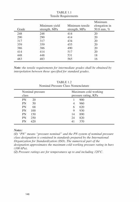
TABLE 1.1Tensile Requirements
MinimumMinimum yield Minimum tensile elongation in
Grade strength, MPa strength, MPa 50.8 mm, %248 248 414 20290 290 414 20317 317 434 20359 359 455 20386 386 490 20414 414 517 20448 448 531 18483 483 565 16
Note: the tensile requirements for intermediate grades shall be obtained byinterpolation between those specified for standard grades.
TABLE 1.2Nominal Pressure Class Nomenclature
Nominal pressure Maximum cold workingclass pressure rating, KPaPN 20 1 900PN 50 4 960PN 68 6 620PN 100 9 930PN 150 14 890PN 250 24 820PN 420 41 370
Notes:(1) “PN” means “pressure nominal” and the PN system of nominal pressureclass designation is contained in standards prepared by the InternationalOrganization for Standardization (ISO). The numerical part of thedesignation approximates the maximum cold working pressure rating in bars(100 kPa).(2) Pressure ratings are for temperatures up to and including 120˚C.
147
148
TABLE 7.2Compliance Factor (F) — Carbon Equivalent Formula
Compliance Compliance ComplianceCarbon (%) factor Carbon factor Carbon (%) factor<0.06 0.53 0.11 0.70 0.17 0.940.06 0.54 0.12 0.75 0.18 0.960.07 0.56 0.13 0.80 0.19 0.970.08 0.58 0.14 0.85 0.20 0.980.09 0.62 0.15 0.88 0.21 0.990.10 0.66 0.16 0.92 >0.21 1.00
TABLE 9.1Location of Test Samples and Frequency of Testing for Bends
Manufacturing procedure Test locations
Cold bends Outer radius, weld seam, tangentHot bends, ower than Grade 290 Outer radius, weld seam, tangentHot bends, Grade 290 or higher Outer radius, inner radius, weld seam
neutral axis, tangent
Notes:(1) New sets of tests, as described in Clause 9.1.4, are required for changesin grade, wall thickness, outside diameter, or heat number.(2) Where a post-bend heat treatment is done, the bends represented by a setof tests shall be(a) heat treated in the same charge as the test samples; or(b) heat treated in the same manner as the test samples; however, in one ormore furnaces that are surveyed at least annually, controlled within a rangeof 30˚C, and equipped with recording sensors that are calibrated at leastquarterly.(3) Testing of tangents is not required if a post-bend heat treatment is notperformed.(4) Testing of weld seams is not required for welds made without the additionof extraneous metal.

149
TABLE 7.1Chemical Composition Limits for Heat and Product Analysis
Grades Maximum carbon equivalent*, %Grade 290and higher 0.50
Maximum permitted, %Lower than Grade 290 Grade 290 or higher
Element heat analysis product analysisCarbon 0.35 0.30Manganese 1.35 1.60Phosphorus 0.05 0.05Sulphur 0.06 0.06Silicon 0.35 0.50Copper - 1.50Nickel - 1.00Chromium - 0.25Molybdenum - 0.25Vanadium - 0.13Niobium - 0.10Boron - 0.001
*The carbon equivalent shall be determined from the product analysis byusing the following formula:
where F is a compliance factor that is dependent on carbon content and isgiven in Table 7.2.
Notes:(1) The chemical requirements of this Table are not intended to represent thecomposition of any heat of steel but to record the maximum permissibleamounts of individual elements.(2) Niobium is also known as columbium.

NOTES:
150