oipf release 2 specification volume 4a – examples of … specification provides informative...
TRANSCRIPT

OIPF
Release 2 Specification
Volume 4a – Examples of IPTV Protocol Sequences
[V2.3] – [2014-01-24]
Open IPTV Forum

Page 2 (79)
Volume 4a - Examples of IPTV Protocol Sequences Copyright 2014 © Open IPTV Forum e.V.
Open IPTV Forum
Postal address
Open IPTV Forum support office address 650 Route des Lucioles – Sophia Antipolis
Valbonne – FRANCE Tel.: +33 4 92 94 43 83 Fax: +33 4 92 38 52 90
Internet http://www.oipf.tv
Disclaimer
The Open IPTV Forum accepts no liability whatsoever for any use of this document.
Copyright Notification
No part may be reproduced except as authorized by written permission. Any form of reproduction and/or distribution of these works is prohibited.
Copyright © 2014 Open IPTV Forum e.V.
All rights reserved.

Page 3 (79)
Volume 4a - Examples of IPTV Protocol Sequences Copyright 2014 © Open IPTV Forum e.V.
Contents FOREWORD .................................................................................................................................................................... 7
INTRODUCTION ............................................................................................................................................................ 7
1 REFERENCES ...................................................................................................................................................... 8 1.1 Normative References ........................................................................................................................................ 8 1.2 Open IPTV Forum References .......................................................................................................................... 8 1.3 Informative References ...................................................................................................................................... 8
2 CONVENTIONS AND TERMINOLOGY .......................................................................................................... 9 2.1 Conventions ......................................................................................................................................................... 9 2.2 Terminology ........................................................................................................................................................ 9 2.2.1 Definitions ............................................................................................................................................................ 9 2.2.2 Abbreviations ....................................................................................................................................................... 9
3 RELEASE 2 INTERFACES ............................................................................................................................... 10 3.1 Consumer Network to Provider Network Interfaces (UNI) ......................................................................... 10 3.2 Provider Network Reference Points Description ........................................................................................... 10 3.3 Interfaces to External Systems ........................................................................................................................ 10
4 EXAMPLES OF IPTV PROTOCOL SEQUENCES ....................................................................................... 11 4.1 IPTV Service Functions Protocol Sequences ................................................................................................. 11 4.1.1 COD Sequences .................................................................................................................................................. 11 4.1.1.1 RTSP specific usage on UNIS-11 and NPI-10 for the managed model ........................................................ 11 4.1.1.2 RTSP specific usage on UNIS-11 and NPI-10 for the unmanaged model .................................................... 12 4.1.2 Content Reporting and Content Reporting Management ................................................................................... 13 4.1.2.1 Content Reporting ......................................................................................................................................... 13 4.1.2.2 Management of Content Reporting ............................................................................................................... 13 4.1.3 Purchase of Digital Media .................................................................................................................................. 14 4.1.3.1 Purchase Request procedure of selected Digital Media related to the content .............................................. 14 4.1.4 Pay Per View ...................................................................................................................................................... 16 4.1.4.1 PPV service initiation without existing Scheduled Content session ............................................................. 16 4.1.4.1.1 User-initiated switch from PPV service to a Scheduled Content service ............................................. 18 4.1.4.1.2 User-initiated switch from regular Scheduled Content to PPV service ................................................ 18 4.1.4.2 User-initiated PPV service switched from the Scheduled Content service ................................................... 18 4.1.4.2.1 User-initiated switch from PPV service to a Scheduled Content service ............................................. 19 4.1.4.2.2 User-initiated switch from a PPV service to another PPV service ....................................................... 19 4.1.5 Network-based Scheduled Content Time Shift .................................................................................................. 19 4.1.5.1 User Activation for Scheduled Content Time Shift ...................................................................................... 19 4.1.5.2 User Deactivation for Scheduled Content Time Shift ................................................................................... 20 4.1.6 What is on TV Service ....................................................................................................................................... 21 4.1.7 What is on TV Service – SMS Initiated ............................................................................................................. 22 4.1.8 Parental Control for Scheduled Content Sequences ........................................................................................... 23 4.1.9 Network-based User Notification Services ........................................................................................................ 24 4.1.9.1 Native HNI-IGI (IMS) based User Notification Setup Request .................................................................... 24 4.1.9.2 DAE-based User Notification Setup Request ............................................................................................... 25 4.1.9.3 Native HNI-IGI Update of Pending Notification Requests ........................................................................... 26 4.1.9.4 DAE-based Update of Pending Notification Requests .................................................................................. 27 4.1.9.5 DAE-based Fetching of Pending Notification Requests ............................................................................... 28 4.1.9.6 Sending a Notification to an OITF ................................................................................................................ 29 4.1.9.7 Sending a Notification to a Cellular Device .................................................................................................. 29 4.1.10 Content Bookmarking ........................................................................................................................................ 30 4.1.10.1 Content Bookmarking in a Scheduled Content Session ................................................................................ 30 4.1.10.2 Content Bookmarking in a CoD Session....................................................................................................... 31 4.1.10.3 Content-related bookmark retrieval .............................................................................................................. 32 4.1.10.4 Content Bookmark Update (DAE-Based) ..................................................................................................... 33 4.1.11 Personalised Channel ......................................................................................................................................... 34 4.1.11.1 PCh Profile Configuration ............................................................................................................................ 34 4.1.11.2 PCh Service Provision .................................................................................................................................. 35 4.1.12 Local PVR .......................................................................................................................................................... 38 4.1.12.1 Local Request for Service Provider Controlled Local PVR Recording ........................................................ 38

Page 4 (79)
Volume 4a - Examples of IPTV Protocol Sequences Copyright 2014 © Open IPTV Forum e.V.
4.1.12.2 Remote Request for Service Provider Controlled Local PVR Recording ..................................................... 39 4.1.13 Network PVR (nPVR) (managed model) ........................................................................................................... 41 4.1.13.1 OITF-initiated nPVR Recording – Synchronous Method ............................................................................. 41 4.1.13.2 OITF-initiated nPVR Recording – Asynchronous Method ........................................................................... 44 4.1.13.3 Remote request from a non-OITF device for a PVR Recording ................................................................... 46 4.1.14 Personalised Channel ......................................................................................................................................... 47 4.1.14.1 OITF-Centric Personalised Channel ............................................................................................................. 47 4.1.15 Notification Service ............................................................................................................................................ 49 4.1.15.1 Emergency Notification service .................................................................................................................... 49 4.1.15.2 Network Generated Notification Service ...................................................................................................... 50 4.1.15.3 Example – Push Mode .................................................................................................................................. 51 4.1.15.4 Generic Procedures ....................................................................................................................................... 52 4.1.15.4.1 Target Device (Transferee OITF) initiating a new Session associated with Session Transfer ............. 52 4.1.15.4.2 IG handling of Session Initiation Requests Associated with Session Transfers ................................... 53 4.1.15.5 Session Transfer – Push Mode ...................................................................................................................... 54 4.1.15.5.1 Transferor initiating a transfer Request to a Transferee (Target Device) ............................................. 54 4.1.15.5.2 Handling of Post Session Initiation setup by Target Device (Transferee OITF) .................................. 55 4.2 Service Access and Control Function Protocol Sequences ............................................................................ 56 4.2.1 Authentication .................................................................................................................................................... 56 4.2.1.1 User Registration and Authentication in a Managed Model ......................................................................... 56 4.2.1.1.1 Default User Identities Registration ..................................................................................................... 56 4.2.1.1.2 IPTV End User Registration ................................................................................................................ 57 4.2.1.1.3 IPTV End User De-registration ............................................................................................................ 58 4.2.1.1.4 IPTV Default User De-registration ...................................................................................................... 59 4.2.1.1.5 Subscription to the registration-state event package ............................................................................ 59 4.2.2 IPTV Service Profile Manipulation through XCAP ........................................................................................... 60 4.2.3 Setup of RTSP/RTCP performance monitoring for CoD Session in Managed Networks over UNIT-18 .......... 61 4.2.4 Specifying metrics for RTSP/RTCP performance monitoring ........................................................................... 62 4.2.5 Non-native HNI-IGI ........................................................................................................................................... 64 4.3 Communication Services.................................................................................................................................. 66 4.3.1 Instant Messaging ............................................................................................................................................... 66 4.3.1.1 Originating Instant Messages ........................................................................................................................ 66 4.3.1.2 Incoming Instant Messages to IPTV end-users ............................................................................................. 66 4.3.2 Caller ID ............................................................................................................................................................. 67 4.3.2.1 Caller ID as a DAE or Embedded Application ............................................................................................. 67 4.3.2.2 Communication Services – Telephony service (Caller identification) for an incoming IMS voice call. ...... 68 4.3.3 Presence .............................................................................................................................................................. 69 4.3.3.1 End User Presence Services .......................................................................................................................... 69 4.3.3.2 Subscription to Presence ............................................................................................................................... 69 4.3.3.3 Cancellation of Presence Subscription .......................................................................................................... 70 4.3.3.4 Publishing Presence Information .................................................................................................................. 71 4.3.4 Content Sharing .................................................................................................................................................. 72 4.3.4.1 Content Sharing Capability Query ................................................................................................................ 72 4.3.4.2 Content Sharing session origination, session modification and session termination .................................... 73 4.3.4.3 OITF transferring a Content Sharing session ................................................................................................ 75 4.4 Content Preparation ......................................................................................................................................... 76 4.4.1 Encryption sequences ......................................................................................................................................... 76 4.4.1.1 Content on Demand ...................................................................................................................................... 77 4.4.1.2 Scheduled content with periodic key rotation controlled by the Key Management Function ....................... 77 4.4.1.3 Scheduled content with periodic key rotation controlled by the Scheduled Content Encryption
Function ........................................................................................................................................................ 78 4.4.1.4 Scheduled content with event based key rotation ......................................................................................... 79

Page 5 (79)
Volume 4a - Examples of IPTV Protocol Sequences Copyright 2014 © Open IPTV Forum e.V.
Figures Figure 1: RTSP Procedure on UNIS-11 for managed model ............................................................................................ 11 Figure 2: RTSP Usage for COD on UNIS-11 and NPI-10 ............................................................................................... 12 Figure 3: Content Reporting ............................................................................................................................................. 13 Figure 4: Management of Content Reporting ................................................................................................................... 14 Figure 5: Purchase Request Procedure of selected Digital Media related to the Content ................................................. 15 Figure 6: User-initiated PPV service without existing Scheduled Content session .......................................................... 17 Figure 7: User-initiated PPV service switched from the Scheduled Content service ....................................................... 18 Figure 8: IPTV End-user Activation of Scheduled Content Time Shift ........................................................................... 20 Figure 9: IPTV End-user Deactivation of Scheduled Content Time Shift ........................................................................ 21 Figure 10: Acquiring Information on Content streamed on an OITF ............................................................................... 22 Figure 11: Call Flow for an SMS initiated Parental Control Request ............................................................................... 23 Figure 12: Procedure for Parental Control command to change channels ........................................................................ 24 Figure 13: IMS-based User Notification setup Request ................................................................................................... 25 Figure 14: DAE-based User Notification setup Request .................................................................................................. 26 Figure 15: IMS-based Update of Pending Notification Requests ..................................................................................... 27 Figure 16: DAE-based Update of Pending Notification Requests .................................................................................... 28 Figure 17: DAE-based fetching of Pending Notification Requests .................................................................................. 28 Figure 18: Sending a Notification to an OITF .................................................................................................................. 29 Figure 19: Sending a Notification to a Cellular Device .................................................................................................... 30 Figure 20: Content Bookmarking in a Scheduled Content Session .................................................................................. 31 Figure 21: Content Bookmarking in a Content on Demand Session ................................................................................ 32 Figure 22: Content-related Bookmark Retrieval ............................................................................................................... 33 Figure 23: Content Bookmark Update .............................................................................................................................. 34 Figure 24: Signalling flow of PCh Configuration ............................................................................................................. 35 Figure 25: Signalling flow of PCh Service Setup ............................................................................................................. 37 Figure 26: Call flow for a local PVR recording session ................................................................................................... 39 Figure 27: Call flow for a remote request for a local PVR recording session................................................................... 41 Figure 28: Call flow for network PVR recording session - Synchronous ......................................................................... 44 Figure 29: Call flow for Network PVR recording – Asynchronous ................................................................................. 46 Figure 30: OITF-Centric Personalised Channel ................................................................................................................ 47 Figure 31: Retrieving Emergency notifications ................................................................................................................ 49 Figure 32: Procedure for network-generated Notifications .............................................................................................. 51 Figure 33: High Level Session procedure ......................................................................................................................... 52 Figure 34: Target Device Initiating a COD Session in relation to Session Transfer ........................................................ 53 Figure 35: IG Handling of CoD initiated Sessions Associated with Session transfers ..................................................... 54 Figure 36: Transferor imitating a session transfer Request to a transferee in Push Mode ................................................ 55 Figure 37: Post Successful Session establishment by the transferee ................................................................................ 56 Figure 38: Default IMS Public identity Registration procedure in a managed model ...................................................... 57 Figure 39: IPTV end-user IMPU Registration procedure in a managed model ................................................................ 58 Figure 40: IPTV end-user De-registration procedure in a managed model ...................................................................... 58 Figure 41: IPTV Default Identity De-registration procedure in a managed model ........................................................... 59 Figure 42: Call flow for subscription to the registration event ......................................................................................... 60 Figure 43: Service Profile Management Based on XCAP ................................................................................................ 61 Figure 44: Registration for non-native HNI-IGI ............................................................................................................... 65 Figure 45: Instant Message Origination Call Flow ........................................................................................................... 66 Figure 46: Incoming Message Call Flow .......................................................................................................................... 67 Figure 47: Caller identification Call Flow ........................................................................................................................ 68

Page 6 (79)
Volume 4a - Examples of IPTV Protocol Sequences Copyright 2014 © Open IPTV Forum e.V.
Figure 48: IMS telephony service based caller identification ........................................................................................... 69 Figure 49: Subscription to Presence ................................................................................................................................. 70 Figure 50: Cancellation of Presence Subscription ............................................................................................................ 71 Figure 51: Publishing a Presence Event ............................................................................................................................ 72 Figure 52: Content Sharing Capability call flow .............................................................................................................. 73 Figure 53: Content Sharing session initiation, modification and terminaion .................................................................... 74 Figure 54: Content Sharing session transfer ..................................................................................................................... 76 Figure 55: Multi-DRM main workflows ........................................................................................................................... 76 Figure 56: Encrypt Content on Demand ........................................................................................................................... 77 Figure 57: Encrypt scheduled content with periodic key rotation controlled by the Key Management Function ............ 78 Figure 58: Encrypt scheduled content with periodic key rotation controlled by Scheduled Content Encryption Function
.................................................................................................................................................................................. 78 Figure 59: Encrypt scheduled content with event based key rotation ............................................................................... 79

Page 7 (79)
Volume 4a - Examples of IPTV Protocol Sequences Copyright 2014 © Open IPTV Forum e.V.
Foreword This informative Technical Specification (TS) has been produced by the Open IPTV Forum.
This specification provides informative examples of features defined in Volume 4. As such, this is not a stand-alone document and must be read in conjunction with Volume 4.
This document is Volume 4a in the 10 Volume set of specifications that define the Open IPTV Forum Release 2 Solution. Other Volumes in the set are:
• Volume 1 – Overview
• Volume 2 – Media Formats
• Volume 2a – HTTP Adaptive Streaming
• Volume 3 – Content Metadata
• Volume 4 – Protocols
• Volume 5 – Declarative Application Environment
• Volume 5a – Web Standards TV Profile
• Volume 6 – Procedural Application Environment
• Volume 7 – Authentication, Content Protection and Service Protection
Introduction This document provides non-normative examples of call flows that realize the functionality defined in Volume 4 [OIPF_PROT2]. As such, this document cannot be taken in a stand-alone manner, but rather must be read alongside Volume 4 in order to gain an understanding of the mechanisms behind the call flows. The interfaces demonstrated in this document include:
• The UNI interfaces, between the network or service provider domains and the consumer domain
• The HNI interfaces, between the functional entities in the consumer network domain
• The NPI interfaces, between the functional entities in the network and service provider domains
• Interfaces to external systems, which include
• DLNA networks in the consumer domain For the details on the requirements and function of these interfaces, please see Volume 4 [OIPF_PROT2].

Page 8 (79)
Volume 4a - Examples of IPTV Protocol Sequences Copyright 2014 © Open IPTV Forum e.V.
1 References
1.1 Normative References [SIP] IETF, RFC 3261, “SIP: Session Initiation Protocol”
[XCAP] IETF, RFC 4825, “The Extensible Markup Language (XML) Configuration Access Protocol (XCAP)”
[RFC3455] IETF, RFC 3455, “Private Header (P-Header) Extensions to the Session Initiation. Protocol (SIP) for the 3rd-Generation Partnership Project (3GPP)”
[RTCP-XR] IETF, RFC 3611, “RTP Control Protocol Extended Reports (RTCP XR)”
[TR135] Broadband Forum, TR-135, “Data Model for a TR-069 Enabled STB”
[ParlayXSMS] 3GPP, 29.199-4, “Open Service Access (OSA); Parlay X web services; Part 4: Short messaging”
[RFC3588] IETF, RFC 3588, “Diameter Base Protocol”
1.2 Open IPTV Forum References [OIPF_PROT2] Open IPTV Forum, “Release 2 Solution Specification, Volume 4 - Protocols”, V2.3, January 2014.
[OIPF_CSP2] Open IPTV Forum, “Release 2 Solution Specification, Volume 7 - Authentication, Content Protection and Service Protection”, V2.3, January 2014.
1.3 Informative References [RFC2119] IETF, RFC 2119, “Key words for use in RFCs to Indicate Requirement Levels”

Page 9 (79)
Volume 4a - Examples of IPTV Protocol Sequences Copyright 2014 © Open IPTV Forum e.V.
2 Conventions and Terminology
2.1 Conventions The key words “MUST”, “MUST NOT”, “REQUIRED”, “SHALL”, “SHALL NOT”, “SHOULD”, “SHOULD NOT”, “RECOMMENDED”, “MAY”, and “OPTIONAL” in this document are to be interpreted as described in RFC2119 [RFC2119]. All sections and annexes, except “Introduction”, are normative, unless they are explicitly indicated to be informative.
2.2 Terminology
2.2.1 Definitions
Term Definition
Native HNI-IGI function (often shortened to Native HNI-IGI)
The procedures for interactions on the HNI-IGI interface are provided as part of the OITF implementation - typically in native code.
Non-native HNI-IGI function (often shortened to Non-native HNI-IGI)
The procedures for interactions on the HNI-IGI interface are provided by a service provider in JavaScript as part of a DAE application.
2.2.2 Abbreviations In addition to the abbreviations provided in Volume 1, the following abbreviations are used in this Volume.
Acronym Definition
FCC Fast Channel Change
GSMA GSM Association
ISC IMS Service Control
PPV Pay Per View
RET RETransmission Function
RFC Request For Comments
XCAP XML Configuration Access Protocol
XDM XML Document Management

Page 10 (79)
Volume 4a - Examples of IPTV Protocol Sequences Copyright 2014 © Open IPTV Forum e.V.
3 Release 2 Interfaces
3.1 Consumer Network to Provider Network Interfaces (UNI) Refer to section 3.1 of [OIPF_PROT2].
3.2 Provider Network Reference Points Description Refer to section 3.2 of [OIPF_PROT2].
3.3 Interfaces to External Systems Refer to section 3.3 of [OIPF_PROT2].

Page 11 (79)
Volume 4a - Examples of IPTV Protocol Sequences Copyright 2014 © Open IPTV Forum e.V.
4 Examples of IPTV Protocol Sequences All the examples in this document are based on the HNI-IGI HTTP Option.
4.1 IPTV Service Functions Protocol Sequences
4.1.1 COD Sequences
4.1.1.1 RTSP specific usage on UNIS-11 and NPI-10 for the managed model In this example, the RTSP delivery parameters have been obtained as indicated in Volume 4 [OIPF_PROT2].
The RTSP URI is: rtsp://Cluster.orangeCDN.net/chevaliers_du_ciel
The session ID is 940211290776250
Figure 1: RTSP Procedure on UNIS-11 for managed model
Step 1: The OITF sends an RTSP PLAY to the Cluster Controller
PLAY rtsp://Cluster.orangeCDN.net/chevaliers_du_ciel CSeq: 1981 Session: 940211290776250
Step 2: The Cluster Controller forwards the PLAY message to the CDF
PLAY rtsp://server1.Cluster.orangeCDN.net/chevaliers_du_ciel CSeq: 1981 Session: 940211290776250
Step 3: The CDF replies to the Cluster Controller
200 OK CSeq: 1981 Session: 940211290776250
Step 4: The Cluster Controller replies to the OITF with the appropriate RTSP session ID
200 OK CSeq: 1981 Session: 940211290776250

Page 12 (79)
Volume 4a - Examples of IPTV Protocol Sequences Copyright 2014 © Open IPTV Forum e.V.
Step 5: The RTP media starts
4.1.1.2 RTSP specific usage on UNIS-11 and NPI-10 for the unmanaged model The following example is only one example of performing redirection at initiation using the 303 Moved message. It does not take into account the effects of Network Address Translation (NAT).
Figure 2: RTSP Usage for COD on UNIS-11 and NPI-10
Step 1: The OITF to the Cluster Controller
DESCRIBE rtsp://Cluster.orangeCDN.net/chevaliers_du_ciel RTSP/1.0 CSeq 1306 Accept: application/sdp
Step 2: The Cluster Controller responds to the OITF indicating redirection to Cluster Controller B
RTSP/1.0 302 Moved Temporarily CSeq 1306 Location: rtsp://Cluster_B.orangeCDN.net/ chevaliers_du_ciel RTSP/1.0
Step 3: The OITF sends a DESCRIBE to the indicated Cluster Controller
DESCRIBE rtsp://Cluster_B.orangeCDN.net/chevaliers_du_ciel CSeq: 1979 Accept: application/sdp
Step 4: The Cluster Controller chooses the appropriate CDF and forwards the DESCRIBE message to it
DESCRIBE rtsp://Server1.orangeCDN.net/chevaliers_du_ciel RTSP/1.0 Cseq: 1979 Accept: application/sdp
Step 5: The CDF replies to the Cluster Controller with the appropriate SDP
200 OK Cseq: 1979 Content-Type: application/sdp Content length: ….. //// SDP////
Step 6: The Cluster Controller replies to OITF with the appropriate SDP

Page 13 (79)
Volume 4a - Examples of IPTV Protocol Sequences Copyright 2014 © Open IPTV Forum e.V.
200 OK CSeq: 1979 Content-Type: application/sdp Content length: … ////SDP ////
4.1.2 Content Reporting and Content Reporting Management
4.1.2.1 Content Reporting Figure 3 shows a call flow for an OITF initiating content reporting. Below is a brief description of the call flow:
Step 1: It is assumed that the OITF established a regular scheduled content session, and that the IPTV Control FE indicated its willingness to receive Content Reporting Info Package (through Recv-Info header in SIP 200 OK response to the INVITE). It is assumed that the timer for content reporting is pre-configured.
Step 2: If zapping is performed and stopped for the configured timer or in case of powerup without zapping and the user settled on a channel for the configured timer, the OITF issues a request to the IG for content reporting.
Step 3: The IG validates the request then issues a SIP INFO to the network including the Content Reporting Info Package to report the watched content
Step 4: The ASM forwards the request to the IPTV control FE.
Steps 5-7: The IPTV control FE generates a 200 OK that is proxied all the way to the IG, then from the IG to the OITF it is forwarded in an HTTP 200 OK response.
Step 8: The user performs channel zapping
Step 9: The user stops zapping and finally settles on a channel for the configured timer.
Step 10: This step reports the watched content and is similar to steps 2-7.
OITF IG RACASM
IPTVControl
Transport Processing
Function
1. Scheduled Content Session established
10. Report watched Content (steps 2-7)
4. SIP INFO (Info Package= Content Reporting)
6. 200 OK () 7. 200 OK
5. SIP INFO (info Package = Content Reporting)
3. HTTP POST ( <HTTP headers>, <SIP Headers>, SIP INFO
8. 200 OK HTTP (<HTTP Headers> <SIP Headers> SIP 200 OK)
4. SIP INFO (Info Package= Content Reporting)
6. 200 OK () 7. 200 OK
5. SIP INFO (info Package = Content Reporting)
3. HTTP POST ( <HTTP headers>, <SIP Headers>, SIP INFO
8. 200 OK HTTP (<HTTP Headers> <SIP Headers> SIP 200 OK)
9. User stop Channel Zapping for a minimum configurable period 9. User stop Channel Zapping for a minimum configurable period
2. User performs zapping then stops for the configured time. or after powerupuser settles on a channel (without zapping) for the configured timer
Figure 3: Content Reporting
4.1.2.2 Management of Content Reporting Figure 4 shows a call flow for the management of content reporting. Below is a brief description of the call flow:
Step 1: The OITF established a scheduled content and performs content reporting as required by the IPTV Control FE.
Step 2: The OITF performs content reporting when user performs zapping then stops for the configured time.

Page 14 (79)
Volume 4a - Examples of IPTV Protocol Sequences Copyright 2014 © Open IPTV Forum e.V.
Step 3: The OITF issues an HTTP HNI-IG PENDING_IG request to the IG. This request can be issued at any time after step 1.
Step 4: At some point in time, the IPTV control FE decided that it does not want any more content reporting. The IPTV control FE sends a SIP UPDATE with the Recv-Info header set to ‘nil’ to the ASM to that effect.
Step 5: The ASM forwards the SIP UPDATE to the IG.
Step 6: The IG forwards the SIP UPDATE in an HTTP 200 OK response to the OITF
Steps 7-9: The OITF issues an HTTP POST request to the IG that includes the SIP 200 OK response. The SIP 200 OK is forwarded all the way to the IPTV control FE.
Step 10: The user performs channel zapping and no content reporting is performed
Step 11: The OITF issues an HTTP HNI-IGI PENDING_IG request to the IG.
Steps 12-14: These steps request the OITF to start reporting the watched content and are similar to steps 4-6. The difference being that the Recv-Info header is set to Content Reporting Info Package
Steps 15-17: The OITF issues an HTTP POST request to the IG that includes the SIP 200 OK response. The SIP 200 OK is forwarded all the way to the IPTV Control FE.
Step 18: This step reports the watched content. See Figure 3 for detailed call flow.
OITFOITF IGIG RAC ASMASMIPTV
ControlTransport
Processing Function
1. Scheduled Content Session established and IPTV Control FE indicate its willingness to receive Content Reporting Info Package 1. Scheduled Content Session established and IPTV Control FE indicate its willingness to receive Content Reporting Info Package
8. 200 OK ()
Trigger to request the OITF to stop Content reporting
4. SIP UPDATE (Recv-info = nil)
9. 200 OK
5. SIP UPDATE (Recv-info = nil)
3. HTTP POST ( <HTTP headers> Pending Request)
6. 200 OK HTTP (<HTTP Headers> <SIP Headers> SIP UPDATE)
7. HTTP POST ( <HTTP headers>, <SIP Headers>, 200 OK)
10. User performs zapping but no content reporting is performed
2. Content Reporting is performed when user stops zapping for a configurable period of time 2. Content Reporting is performed when user stops zapping for a configurable period of time
16. 200 OK ()
Trigger to request the OITF to resume Content reporting
12. SIP UPDATE (Recv-info = Content Reporting Info Package
17. 200 OK
13. SIP UPDATE (Recv-info=Content Reporting Info Package)
11. HTTP POST ( <HTTP headers> Pending Request)
14. 200 OK HTTP (<HTTP Headers> <SIP Headers> SIP UPDATE)
15. HTTP POST ( <HTTP headers>, <SIP Headers>, 200 OK)
18. Content Reporting is performed when user stops zapping for the configurable period of time 18. Content Reporting is performed when user stops zapping for the configurable period of time
Figure 4: Management of Content Reporting
4.1.3 Purchase of Digital Media
4.1.3.1 Purchase Request procedure of selected Digital Media related to the content Confirmation process: After retrieving and advertising the Digital Media, users can select the Digital Media they want to buy. When a user selects one Digital Media, the OITF pops up a dialog box to let the user confirm the selected Digital Media for purchase purpose.

Page 15 (79)
Volume 4a - Examples of IPTV Protocol Sequences Copyright 2014 © Open IPTV Forum e.V.
Repeat billing check: Before sending the purchase request for Digital Media, the OITF must check the user’s profile first (in order to avoid repeat billing). If the requested Digital Media is already recorded in user’s profile, the OITF pops up a dialog box to let user know the repeat billing, and then stop sending the purchase request.
If the requested Digital Media is not recorded in user’s profile, the OITF sends the HTTP purchase request to IG, and IG generates a SIP request to IPTV Control FE through ASM FE, and then the IPTV Control FE sends the purchase request (ACR) to Charging FE.
After receive the purchase response (ACA) from Charging FE, and if the purchase is successful, the IPTV Control FE sends Digital Purchase Request to IPTV Applications FE to update the user’s profile, and then the IPTV Applications FE sends the XCAP PUT to IPTV Service Profile FE to update the purchased digital media record.
After receive the HTTP response sent from IPTV Service Profile FE, the IPTV Applications FE sends the response to IPTV Control FE. The IPTV Control FE sends the SIP 200 OK response (with no message body) to IG through ASM FE if the purchase request success; otherwise, the IPTV Control FE sends the SIP 403 Forbidden response (the message body is Result-Code that defined in [RFC3588]) to IG through ASM FE. Finally, the IG sends the HTTP 200 OK to OITF with purchase result (it can be either “success” or Result-Code).
Figure 5 shows the purchase request procedure of selected Digital Media related to the content.
OITF IG ASMIPTV
ServiceProfile
IPTV Control
3. HTTP POST (SelectedDigitalMediaURI, UserID)4. SIP INFO (SelectedDigitalMediaURI, UserID)
5. SIP INFO (SelectedDigitalMediaURI, UserID)
13. SIP response (200 OK or 403 Forbidden)
14. HTTP 200 OK (Purchase Result)
12. SIP response (200 OK or 403 Forbidden)
Charging
1. XCAP GET
2. HTTP 200 OK (user’s profile)
6. ACR (SelectedDigitalMediaURI, UserID)
7. ACA (Purchase result)
9. XCAP PUT (SelectedDigitalMediaURI, UserID)
10. HTTP 200 OK
Check repeat billing
OITF has established a schedule content or a CoD session
IPTV Applications
8. Digital Purchase Request (SelectedDigitalMediaURI, UserID)
11. Response
Figure 5: Purchase Request Procedure of selected Digital Media related to the Content
Because the purchase request happen in the period of pause during a Scheduled content (if supported) or a CoD content, the OITF has already established a session between itself and IPTV Control FE. The SIP INFO will use this established session to transmit information about purchase request.
Step 1: The OITF sends XCAP GET to IPTV Service Profile FE to get the user’s profile about Digital Media.
Step 2: The IPTV Service Profile FE returns HTTP 200 OK with user’s profile to OITF. If the requested Digital Media is already recorded in user’s profile, the OITF needs to popup a dialog box to let user know the repeat billing, and then stop sending the purchase request.
Step 3: The OITF sends an HTTP POST (with SelectedDigitalMediaURI, UserID) to IG for purchasing selected Digital Media.

Page 16 (79)
Volume 4a - Examples of IPTV Protocol Sequences Copyright 2014 © Open IPTV Forum e.V.
Step 4: The IG sends a SIP INFO Request (with SelectedDigitalMediaURI, UserID) to ASM FE for authentication.
Step 5: The ASM FE forwards the SIP INFO (with SelectedDigitalMediaURI, UserID) to IPTV Control FE for purchase.
Step 6: The IPTV Control FE sends Accounting-Request (ACR) message (with SelectedDigitalMediaURI, UserID) to Charging FE.
Step 7: The Charging FE returns Accounting-Answer (ACA) message with purchase result (success or fail) to IPTV Control FE.
Step 8: The IPTV Control FE sends the Digital Purchase Request (with SelectedDigitalMediaURI, UserID) to IPTV Applications FE.
Step 9: The IPTV Applications FE issues an XCAP PUT request to IPTV Service Profile FE to update user’s profile (adds a SelectedDigitalMediaURI and/or other information). In order to avoid falsifying the information about Purchase of Digital Media in user’s profile cannot be updated by OITF.
Step 10: The IPTV Service Profile FE returns an HTTP 200 OK to IPTV Applications FE.
Step 11: The IPTV Applications FE returns a response to IPTV Control FE.
Step 12: The IPTV Control FE returns SIP 200 OK (if purchase request success) or 403 Forbidden including Result-Code (if purchase request failure) to ASM FE.
Step 13: The ASM FE forwards SIP 200 OK (if purchase request success) or 403 Forbidden including Result-Code (if purchase request failure) to IG.
Step 14: The IG sends the HTTP response including purchase result to OITF.
4.1.4 Pay Per View The PPV stream may be protected, and the key may be retrieved in the PPV subscription procedure.
4.1.4.1 PPV service initiation without existing Scheduled Content session Figure 6 shows a typical call flow for watching a initiating PPV service without an existing Scheduled Content session.

Page 17 (79)
Volume 4a - Examples of IPTV Protocol Sequences Copyright 2014 © Open IPTV Forum e.V.
OITF RACIG ASM
1. HTTP POST( HTTP Headers, SIP Headers, SIP INVITE, SDP )
2.INVITE(BC service ID, BC program ID)
3. Resource reservation
4..INVITE(BC service ID, BC program ID)
5. 200 OK
6. Resource commit
7. 200 OK
9. IGMP Join
10. Media stream
IPTV Control
8. HTTP 200 OK(SDP) TPF
Figure 6: User-initiated PPV service without existing Scheduled Content session
Step 1: The OITF sends a HTTP POST to the IG to initiate a PPV session.
Step 2: The IG validates the request and sends an INVITE to the ASM.
The ASM uses the services of the “Resource and Admission Control” functional entity to perform resource reservation.
Step 3: The ASM uses the services of the RAC functional entity to perform resource reservation.
Step 4: The ASM forwards the INVITE to the IPTV Control. Using the BC service ID and BC program ID, the IPTV Control verifies that the user has a PPV subscription. The IPTV Control verifies whether the program has started or not. If the program has started and is encrypted, the IPTV Control may interact with CSP functions directly or through the IPTV application to verify the user entitlements, and then performs the following steps. If the program has started and is not encrypted, the IPTV Control performs the following steps. If the program has not started, the IPTV Control refuses the request.
Step 5: The IPTV Control sends a 200 OK response to the ASM with the bandwidth required for the specific scheduled content channels and other parameters.
Step 6: The ASM instructs the RAC to commit the reserved resources.
Step 7: Finally, a 200 OK for the session setup request is forwarded to the OITF.
Step 8: The IG returns the SDP to the OITF in a HTTP 200 OK response.
Step 9: The OITF issues an IGMP Join request to the transport processing functions to access the multicast channel for the PPV service.
Step 10: The media stream is delivered to the OITF.

Page 18 (79)
Volume 4a - Examples of IPTV Protocol Sequences Copyright 2014 © Open IPTV Forum e.V.
4.1.4.1.1 User-initiated switch from PPV service to a Scheduled Content service
The user initiates a switch from the PPV service to a regular Scheduled Content.
If the Scheduled Content service is inside the set of channels negotiated at PPV session initiation, the OITF shall send an IGMP Leave request to stop watching the PPV service, and send an IGMP Join request to join the Scheduled Content service.
If the Scheduled Content service is outside the set of channels negotiated at PPV session initiation, the OITF shall initiate a Scheduled Content Session Modification request as described in Volume 4 [OIPF_PROT2].
4.1.4.1.2 User-initiated switch from regular Scheduled Content to PPV service
The user initiates a switch from the regular Scheduled Content to a PPV service.
The OITF shall initiate a PPV Session Modification request as described in Volume 4 [OIPF_PROT2].
4.1.4.2 User-initiated PPV service switched from the Scheduled Content service Figure 7 shows a typical call flow for watching a PPV service switched from the Scheduled Content service initiated by the user.
OITF RACIG ASM
1. HTTP POST( HTTP Headers, SIP Headers, SIP ReINVITE, SDP )
2.Re-INVITE(BC service ID, BC program ID)
3. Resource modification
4. Re-INVITE(BC service ID, BC program ID)
5. 200 OK
6. Resource commit
7. 200 OK
9. IGMP Join
10. Media stream
IPTV Control
8. HTTP 200 OK(SDP) TPF
Scheduled Content session established
Figure 7: User-initiated PPV service switched from the Scheduled Content service
It is assumed that the user has established a Scheduled Content session. When the user switches from the Scheduled Content service to a PPV service, the OITF shall send a HTTP POST to the IG to modify the Scheduled Content session to a PPV session.

Page 19 (79)
Volume 4a - Examples of IPTV Protocol Sequences Copyright 2014 © Open IPTV Forum e.V.
4.1.4.2.1 User-initiated switch from PPV service to a Scheduled Content service
The user initiates to switch from PPV service to a regular Scheduled Content.
If the Scheduled Content service is inside the set of channels negotiated at PPV session initiation, the OITF shall send an IGMP Leave request to stop watching the PPV service, and send an IGMP Join request to join the Scheduled Content service.
If the Scheduled Content service is outside the set of channels negotiated at PPV session initiation, the OITF shall initiate a Scheduled Content Session Modification request as described in Volume 4 [OIPF_PROT2].
4.1.4.2.2 User-initiated switch from a PPV service to another PPV service
The user initiates to switch from a PPV service to another PPV service.
The OITF shall initiate a PPV Session Modification request as described in Volume 4 [OIPF_PROT2].
4.1.5 Network-based Scheduled Content Time Shift
4.1.5.1 User Activation for Scheduled Content Time Shift Figure 8 shows a call flow for an IPTV end- user activating a scheduled Content Time Shift. Below is a brief description of the call flow (the procedure assumes that the scheduled content to be time shifted is recorded in the network, and is thus available for time shifting)
Step 1: It is assumed that the OITF successfully established a scheduled content session
Step 2: The activation of time shift procedure can be triggered by the user, through a menu selection, invoking the time shift option.
Step 3: The OITF issues a request to the IG to activate the scheduled content time shift.
Step 4: The IG validates the request then issues a SIP re-INVITE to the network.
Step 5: The ASM performs initial resource modification as per the incoming request.
Step 6: The ASM forwards the re-INVITE to the IPTV Control FE.
Step 7: The IPTV Control FE performs the necessary validation as per Volume 4 [OIPF_PROT2].
Steps 8-18: These steps show how the unicast session is established.
Step 19: The IG forwards the SIP 200 OK to the OITF in an HTTP 200 OK response.
Step 20: The OITF issues an HTTP POST request to send an ACK
Steps 21-24: The ACK is propagated to the IPTV Control server FE.
Step 25: OITF can deploy RTSP media control commands to start streaming the unicast content

Page 20 (79)
Volume 4a - Examples of IPTV Protocol Sequences Copyright 2014 © Open IPTV Forum e.V.
CDNCRAC ASM IPTVControl CCOITF IG CDF
2. User selects to time shift scheduled content he is currently watching
5. Initial Resource Modification
6. SIP re-INVITE
7. Validate requestSelect appropriate CDNC where the media is held, modify SDP as required
8. INVITE
4. SIP Re-INVITE
10. INVITE
Select CDF
13. 200 OK
11. RTSP setup
12. 200 OK (RTSP Session id)
1. Scheduled Content Session established
3. HTTP POST (<HTTP headers>, <SIP headers>, SIP re-INVITE)
14. 200 OK (RTSP Session id)
17. Final Resource Modification18. SIP 200 OK
19. 200 OK HTTP (<HTTP Headers> <SIP Headers> SIP 200 OK)
9. INVITE
15. 200 OK (RTSP Session id)
16. 200 OK (RTSP Session id)
20. HTTP Post (<HTTP headers>, <SIP headers>, SIP ACK)
25. RTSP Media Control
21. ACK 22. ACK23. ACK
24. ACK
Figure 8: IPTV End-user Activation of Scheduled Content Time Shift
4.1.5.2 User Deactivation for Scheduled Content Time Shift Figure 9 shows a call flow for an IPTV end- user initiating a de-activation of a scheduled Content Time Shift. Below is a brief description of the call flow:
Step 1: It is assumed that the OITF is successfully streaming a unicast session representing a time shifted scheduled content
Step 2: The procedure can be triggered by the user, through a menu selection, invoking the de-activation of the time shift option.
Step 3: The OITF issues a request to the IG to activate the scheduled content time shift.
Step 4: The IG validates the request then issues a SIP re-INVITE to the network.
Step 5: The ASM performs initial resource modification as per the incoming request.
Step 6: The ASM forwards the re-INVITE to the IPTV Control FE.
Step 7: The IPTV Control FE performs the necessary validation as per Volume 4 [OIPF_PROT2].
Steps 8-18: These steps show how the unicast session is terminated.
Step 19: The IG forwards the SIP 200 OK to the OITF in an HTTP 200 OK response.
Step 20: The OITF issues an HTTP POST request to send an ACK.
Steps 21-24: The ACK is propagated to the IPTV Control server FE.
Step 25: OITF can issue an IGMP JOIN to join the multicast address for the last viewed channel.

Page 21 (79)
Volume 4a - Examples of IPTV Protocol Sequences Copyright 2014 © Open IPTV Forum e.V.
CDNCRAC ASM IPTVControl CCOITF1 IG CDF
2. User selects to go back to scheduled content
5. Initial Resource Modification6. re-INVITE
7. Validate requestSelect appropriate CDNC
8. BYE
4. re-Invite or Update
10. BYE
13. 200 OK
9 BYE.
11. RTSP Tear Down
14. 200 OK ()
17. Final Resource Modification
15. 200 OK
16 200 OK
18. 200 OK
3. HTTP POST ( <HTTP headers>, <SIP Headers>, SIP re-INVITE, or UPDATE
12. 200 OK
19. 200 OK HTTP (<HTTP Headers> <SIP Headers> SIP 200 OK)
OITF sends an IGMP JOIN to the appropriate Multicast address
25. IGMP JOIN
20. HTTP Post (<HTTP headers>, <SIP headers>, SIP ACK)21. ACK 22. ACK
23. ACK
24. ACK
Figure 9: IPTV End-user Deactivation of Scheduled Content Time Shift
4.1.6 What is on TV Service Figure 10 shows a call flow for a user, with parental control authority, acquiring information related to the content being streamed on an OITF, watched by another user under the parental supervision of the request originator. Below is a brief description of the call flow:
Steps 1-4: These steps are optional and show how the IPTV control FE may store state information to support the feature. Optionally this storage may be on the presence server. The rest of the call flow describes this option.
Step 5: The OITF issues an HTTP POST request to subscribe to the Parental Control Watched Content event.
Step 6: The IG validates the request then issues a SIP SUBSCRIBE to the network.
Step 7: The ASM forwards the request to the IPTV control FE.
Steps 8-11: The IPTV control FE validates that the user is allowed to access the requested information. If successful, steps 8-10 are optional and are implemented only if the IPTV control FE uses presence to support the feature as per steps 1-4
Step 12: The IPTV control FE generates a SIP 200 OK if the user is allowed access to requested information or proxies the received 200 OK from the presence server if steps 8-11 are performed. The SIP 200 OK response is sent to the ASM.
Step 13: The ASM proxies the SIP 200 OK response to the IG.
Step 14: The IG returns the SIP 200 OK to the OITF in an HTTP 200 OK response.
Step 15: The OITF issues an HTTP HNI-IGI PENDING_IG request to the IG in anticipation of the incoming SIP NOTIFY
Steps 16-17: These steps are implemented only if the IPTV control FE uses presence per steps 1-4. In these steps, the SIP NOTIFY including the requested information is sent to the IPTV control FE via the ASM.

Page 22 (79)
Volume 4a - Examples of IPTV Protocol Sequences Copyright 2014 © Open IPTV Forum e.V.
Step 18: If presence is not used to support this feature, the IPTV control FE generates the SIP NOTIFY, otherwise the received NOTIFY from the presence server is proxied to the ASM.
Step 19: The ASM proxies the SIP NOTIFY to the IG.
Step 20: The IG forwards the SIP NOTIFY in an HTTP 200 OK response to the OITF
Steps 21-23: The OITF issues an HTTP POST request to the IG that includes the SIP 200 OK response. The SIP 200 OK is forwarded all the way to the IPTV control FE.
Steps 24-25: These steps are optional if presence is used to support the feature.
IGIG ASMASM IPTV ControlServerOITF2
6. SUBSCRIBE (What is on TV7. SUBSCRIBE (What is on TV)
4. .SIP 200 OK ()
13. SIP 200 OK ()
23. SIP 200 OK ()
16. NOTIFY (Information)
20. HTTP 200 OK (SIP NOTIFY)
5. HTTP POST (SIP SUBSCRIBE)
14. HTTP 200 OK (SIP 200 OK)
-
15. HTTP POST (HNG-IGI Pending Request
21 HTTP POST (SIP 200 OK)
19. NOTIFY (Information)
22. SIP 200 OK ()
1. PUBLISH ( user, content information)
2. PUBLISH (user, content information2. PUBLISH (user, content information)
10. SIP 200 OK ()
3. SIP 200 OK ()
9. SUBSCRIBE (What is on TV)
11. SIP 200 OK ()
8. SUBSCRIBE (What is on TV)
24. SIP 200 OK ()
25. SIP 200 OK ()
17. NOTIFY (Information)
18. NOTIFY (Information)
12. SIP 200 OK ()
PresenceServer
Figure 10: Acquiring Information on Content streamed on an OITF
4.1.7 What is on TV Service – SMS Initiated Figure 11 shows a call flow for a user, with parental control authority, acquiring information related to the content being streamed on an OITF, watched by another user under the parental supervision of the request originator. Below is a brief description of the call flow:
Step 1: The end user through his cellular device issues a text message to the MSISDN (or short code) associated with IPTV Application AS supporting the parental control feature to query what content is being watched by another user. The MSISDN (or short code) for this service is allocated by the SP and is given to subscribers who subscribe to this service. The content of the text message is implementation specific.
Step 2: The message is routed through the cellular network to the Notification AS which implements the network side Parlay X SMS Web Service Interfaces [ParlayXSMS].
Step 3: The Notification AS notifies the SMS reception to the IPTV AS which implements the application side Parlay X SMS Web Service Interfaces. The delivery of SMS reception is done by invoking the NotifySMSReception operation in SmsNotification Web Service Interface exposed by the IPTV AS.
Step 4: The IPTV AS sends a request to the IPTV Control FE to query the content being watched by another user. This interface is implementation specific.

Page 23 (79)
Volume 4a - Examples of IPTV Protocol Sequences Copyright 2014 © Open IPTV Forum e.V.
Steps 5-8: The IPTV Control FE authorizes the request. Request authorization can be achieved if the calling subscriber is validated to be the parental control authority for the incoming request. If the request is authorized then steps 5-8 are performed only if the IPTV Control FE uses the presence server for storing watched content by an OITF. In the case where a presence mechanism is used, an extension of the Presence Information Data Model is needed which is vendor specific. Other means are possible but are not described in this specification.
Step 9: The IPTV control FE returns to the IPTV AS the requested information in a response. This interface is implementation specific. Note that the IPTV Control FE may return the requested information per request, or based on a preconfigured time interval, or continuously until the stop request is received, etc.
Step 10: The IPTV AS invokes the SendSms operation in SendSms Web Service Interface exposed by the Notification AS.
Steps 11-12: The message is delivered to the cellular device through the cellular network.
Mobile Phone
Notification AS IPTV AS IPTV ControlOther Delivery
Networks
1. Send SMS (What is on TV)
Parent Control Authorization
Presence Server
2. SMPP (submit_sm)
3. Parlay X SMS Web Service(SMSNotification: NotifySmsReception)
4. Request (What is on TV)
5. SIP SUBSCRIBE
6. SIP 200 OK
7. SIP NOTIFY
8. SIP 200 OK
9. Response (Information)
10. Parlay X SMS Web Service(SendSms: SendSms)
11. SMPP (deliver_sm)
12. Deliver SMS (information)
Figure 11: Call Flow for an SMS initiated Parental Control Request
4.1.8 Parental Control for Scheduled Content Sequences Figure 12 shows a detailed call flow which takes the channel change as an example for the Parental Control command. The following is a brief description of the steps:
Step 1: The child is watching a scheduled content program as described in Volume 4 [OIPF_PROT2].
Step 2: The parent retrieves information related to the watched scheduled content as described in 4.1.6, “What is on TV Service.”
Step 3: The parent decides to block the content being watched by the child. The OITF issues a request to the IG as described in Volume 4 [OIPF_PROT2] and includes the following parameters:
• PC-Command: the command for parental control, e.g. channel change, session teardown.
• PC-ChannelChangedTo: When the PC-Command is channel change, the PC-ChannelChangedTo may be included. It indicates the new channel to change to.

Page 24 (79)
Volume 4a - Examples of IPTV Protocol Sequences Copyright 2014 © Open IPTV Forum e.V.
• PC-ContentControlled: the identifier of the content being blocked by the controller. For scheduled content, it shall be the BC service ID. Controlling Content on Demand is for future study.
Step 4: The IG validates the request and issues a SIP MESSAGE to the ASM as described in Volume 4 [OIPF_PROT2].
Steps 5-7: The ASM routes the SIP MESSAGE to the IPTV Control Function which validates the MESSAGE and checks whether the initiator has the right to perform Parental Control on the other user. Then the IPTV Control function forwards the SIP MESSAGE to the ASM as described in Volume 4 [OIPF_PROT2]. The ASM routes the SIP MESSAGE to the OITF of the controlled user.
Steps 8-10: Upon receiving the SIP MESSAGE, the OITF of the controlled user implements the command according to the PC-Command as described in Volume 4 [OIPF_PROT2].
Steps 11-16: The response to the SIP MESSAGE is sent from the OITF of the controlled user to the OITF of the controller via the IG, ASM and IPTV Control Function.
Parent OITFChild OITF
ASM IPTV Control P2P Communication Presence Enaler
4. MESSAGE
5. MESSAGE
6. MESSAGE7. MESSAGE
TPF
9. IGMP Leave
10. IGMP Join
12. 200 OK13. 200 OK
14. 200 OK
15. 200 OK
IGIG
1. Call flow for scheduled content
2. Call flow for What is on TV
3. Http POST
8. Notification Mechinism
11. Http POST
16. Http 200
Figure 12: Procedure for Parental Control command to change channels
4.1.9 Network-based User Notification Services
4.1.9.1 Native HNI-IGI (IMS) based User Notification Setup Request Figure 13 shows a call flow for a user setting up a notification request. Below is a brief description of the call flow:
Step 1: It is assumed that user is interacting with the EPG and made a selection for a notification request for one of the services offered by the service provider. This could include a broadcast reminder, or services related to recorded content requested by the user
Step 2: The OITF issues an HTTP POST request to the IG to request the service.
Step 3: The IG validates the request then issues a SIP MESSAGE to the network.
Steps 4-5: The Messaging AS validates the request than forwards the request to the IPTV Control FE via the ASM
Step 6: The IPTV Control FE validates the request then issues a store request to the appropriate IPTV application.

Page 25 (79)
Volume 4a - Examples of IPTV Protocol Sequences Copyright 2014 © Open IPTV Forum e.V.
Step 7: The IPTV application validates the included schema, then issues an XCAP PUT request to the IPTV service profile
Step 8: The IPTV service profile returns an HTTP 200 OK to the IPTV AS.
Step 9: The IPTV AS returns a response to the IPTV control FE.
Steps 10-13: The IPTV control FE generates a SIP 200 OK that reaches the IG via the ASM.
Step 14: The IG returns the SIP 200 OK to the OITF in an HTTP 200 OK response.
IPTVServiceProfile
IPTVControlIGOITF
2. SIP MESSAGE (notification Request)
7. XCAP PUT (Notification Request)
8. HTTP 200 OK
1.HTTP POST (<HTTP Headers>, <SIP Headers>, SIP MESSAGE)
IPTVApplication
14. HTTP 200 OK (200 OK)
6. Store request (Notification Request)
IPTV Metadata Control
User interacts with EPG to select one of offered services
ASM
Validate the content against schema
MessagingAS
3. SIP MESSAGE (Notification Request)
4. SIP MESSAGE (Notification Request)
5. SIP MESSAGE (Notification Request)
9. Response
10. SIP 200 OK
11. SIP 200 OK
12. SIP 200 OK13. SIP 200 OK
Figure 13: IMS-based User Notification setup Request
4.1.9.2 DAE-based User Notification Setup Request Figure 14 shows a call flow for a DAE-based user notification setup request. Below is a brief description of the call flow:
It is assumed that user is interacting with the EPG and made a selection for a notification request for one of the services offered by the service provider. This could include a broadcast reminder, or services related to recorded content requested by the user
Step 1: The OITF sends an HTTP PUT to the IPTV application to submit the notification setup request.
Step 2: The IPTV application authorizes and validates the request. Upon successful completion of the above, it sends an XCAP PUT request to the IPTV service profile to store the request.
Step 3: The response is returned by the IPTV service profile in an HTTP 200 OK response
Step 4: The IPTV Application in turn returns the response to the OITF in an HTTP 200 OK response

Page 26 (79)
Volume 4a - Examples of IPTV Protocol Sequences Copyright 2014 © Open IPTV Forum e.V.
Figure 14: DAE-based User Notification setup Request
4.1.9.3 Native HNI-IGI Update of Pending Notification Requests Figure 15 shows an IMS-based call flow for updating pending user notification requests.
Below is a brief description of the call flow:
Step 1: The OITF issues an XCAP GET request to the IPTV service profile to fetch all outstanding notification requests
Step 2: The IPTV service profile returns the requested data in an HTTP 200 OK response.
Step 3: The user performs the necessary modification
Step 4: The OITF issues an XCAP PUT request to the IPTV service profile to store the updated the list of pending notification requests
Step 5: The IPTV service profile updates the IPTV Control FE in regard the changes to the list of pending notification requests.
Step 6: The IPTV Control FE sends a update request to the IPTV application so it can update its state.
Step 7: The IPTV application updates its internal state
Step 8: The IPTV application then acknowledges the request to the IPTV Control FE.
Step 9: The IPTV Control FE acknowledges the request to the IPTV Service profile.
Step 10: The IPTV Service Profile returns an HTTP 200 OK response to the OITF.

Page 27 (79)
Volume 4a - Examples of IPTV Protocol Sequences Copyright 2014 © Open IPTV Forum e.V.
ASMIPTV
ServiceProfile
IPTVControlIGOITF
1. XCAP GET (List of Pending Notification Services)
CDFIPTVApplication
2. HTTP 200 OK (data)
3. Update XML Page to delete
request
4. XCAP PUT (Update List of Pending Notification Services)
7. Update internal state
5. Notify Request ()
9. Response ()
6. Update Pending Requests (request ID)
8. Response ()
10. HTTP 200 OK ()
Figure 15: IMS-based Update of Pending Notification Requests
4.1.9.4 DAE-based Update of Pending Notification Requests Figure 16 shows a DAE-based call flow for update of pending user requests.
Below is a brief description of the call flow:
Step 1: The OITF issues an HTTP GET request to the IPTV application service profile to fetch all outstanding notification requests.
Step 2: The IPTV application validates and authorizes the request. Upon successful completion of the above, it sends an XCAP GET request to the IPTV service profile to store the request.
Step 3: The response is returned by the IPTV service profile in an HTTP 200 OK response
Step 4: The IPTV Application in turn returns the response to the OITF in an HTTP 200 OK response
Step 5: The user performs the necessary modification
Step 6: The OITF issues an HTTP PUT request to the IPTV application service profile to update pending notification requests.
Step 7: The IPTV application validates and authorizes the request. Upon successful completion of the above, it updates its internal state.
Step 8: Following that, the IPTV application sends an XCAP PUT request to the IPTV service profile to store the updated pending requests
Step 9: The response is returned by the IPTV service profile in an HTTP 200 OK response
Step 10: The IPTV Application in turn returns the response to the OITF in an HTTP 200 OK response

Page 28 (79)
Volume 4a - Examples of IPTV Protocol Sequences Copyright 2014 © Open IPTV Forum e.V.
ASMIPTV
ServiceProfile
IPTVControlIGOITF CDFIPTV
Application
10. HTTP 200 OK ()
9. HTTP 200 OK ()
7. Update internal state
1. HTTP GET (List Pending Notification Requests)
3. HTTP 200 OK (data)
2. XCAP GET (List of Pending Notification Requests)
4. HTTP 200 OK ()
5. Update XML Page to delete
Request
6. HTTP POST (Update List of Pending Notification Requests)
8. XCAP PUT (Update List of Pending Notification Requests)
Figure 16: DAE-based Update of Pending Notification Requests
4.1.9.5 DAE-based Fetching of Pending Notification Requests Figure 17 shows a DAE-based call flow for fetching all pending user requests. Below is a brief description of the call flow:
Step 1: The OITF issues an HTTP GET request to the IPTV application service profile to fetch all outstanding notification requests.
Step 2: The IPTV application validates and authorizes the request. Upon successful completion of the above, it sends an XCAP GET request to the IPTV service profile to fetch all outstanding requests.
Step 3: The response is returned by the IPTV service profile in an HTTP 200 OK response
Step 4: The IPTV application, in turn, returns an HTTP 200 OK response to the OITF.
ASMIPTV
ServiceProfile
IPTVControlIGOITF
1. HTTP GET (List of Pending Notification Requests)
CDFIPTVApplication
3. HTTP 200 OK (data)
2. XCAP GET (List of Pending Notification Requests)
4. HTTP 200 OK (data)
Figure 17: DAE-based fetching of Pending Notification Requests

Page 29 (79)
Volume 4a - Examples of IPTV Protocol Sequences Copyright 2014 © Open IPTV Forum e.V.
4.1.9.6 Sending a Notification to an OITF Figure 18 shows a Notification sent to an OITF using IMS pager mode (SIP MESSAGE).
Below is a brief description of the call flow:
Steps 1-2: The IPTV Application fetches the user preference for delivering a notification to an end user using XCAP for that purpose.
Step 3: The OITF has an HTTP pending request in anticipation of an incoming MESSAGE
Step 4: An IPTV Application that wants to send an IMS pager mode notification to an OITF issues an HTTP POST request to invoke the SendMessage operation on the Notification Services AS (MMS Parlay X web services AS). The requested message format shall be IMPagerMode based on the user preference fetched in previous steps.
Step 5: The Notification Services AS, issues a corresponding SIP MESSAGE to the IMS AS for delivery towards the intended user.
Steps 6-7: The SIP MESSAGE reaches the IG via the ASM.
Step 8: The messages is sent to the OITF in an HTTP 200 OK response.
Step 9: The OITF issues an HTTP POST HTTP pending request that includes the SIP 200 OK response to acknowledge the incoming notification.
Steps 10-12: The SIP 200 OK is transferred from the IG to the Notification services AS via the ASM.
Step 13: The Notification services AS sends an HTTP 200 OK response to the IPTV application
Step 14: The IPTV application updates its internal state
Steps 15-16: The IPTV Application uses XCAP to update the user service profile to reflect the outcome
OITF
9. HTTP POST (<HTTP Headers>, <SIP Headers> Pending Request10. SIP 200 OK 12. SIP 200 OK
IG ASM
Notification Services(MMS Parlay XWeb Services)
IPTVApplication
IM AS
5. SIP MESSAGE (notification or URL)6. SIP MESSAGE
11. SIP 200 OK 13. HTTP 200 OK
7. HTTP 200 OK (Message)
4. HTTP POST (SendMessage Operation – MessageFormat set to IMPagerMode)3. HTTP POST (<HTTP Headers>, Pending Request )
IPTVServiceProfile
14. Update internal state
16. HTTP 200 OK ()
15. XCAP PUT (Notification Requests)
2. HTTP 200 OK ()
1. XCAP GET (User Preference for Delivery)
8. HTTP 200 OK (<HTTP Headers>, <SIP Headers>, SIP MESSSAGE)
3. HTTP POST (<HTTP Headers>, Pending Request )
Figure 18: Sending a Notification to an OITF
4.1.9.7 Sending a Notification to a Cellular Device Figure 19 shows a Notification sent to a cellular device
Below is a brief description of the call flow:
Steps 1-2: The IPTV Application fetches the user preference for delivering a notification to an end user using XCAP for that purpose.
Step 3: An IPTV Application that wants to send an SMS notification to a cellular device OITF sends an HTTP POST request to invoke the SendSms operation on the SMS Parlay X web services AS based on user preference.

Page 30 (79)
Volume 4a - Examples of IPTV Protocol Sequences Copyright 2014 © Open IPTV Forum e.V.
Step 4: The SMS Parlay X web services AS submits the corresponding message to the SMS-SC using standard procedures.
Step 5: The SMS-SC delivers the SMS to the mobile via the cellular network
Step 6: The SMS Parlay X web services AS sends an HTTP 200 OK response to the IPTV application,
Step 7: The IPTV application updates its internal state
Steps 8-9: The IPTV Application uses XCAP to update the user service profile to reflect the outcome
Figure 19: Sending a Notification to a Cellular Device
4.1.10 Content Bookmarking
4.1.10.1 Content Bookmarking in a Scheduled Content Session Content bookmarking in a scheduled content session essentially represents a mark in a file stored in the network for the scheduled content. As such, it is a pre-requisite that the scheduled content be stored in the network for any bookmarking to be available for a scheduled content. The stored bookmarking hence will be a pointer in the network stored scheduled content
Figure 20 shows a call flow for a user requesting a content bookmark to be stored within a scheduled content session. This call flows assumes that the scheduled content is already stored in the network. Below is a brief description of the call flow:
Step 1: As a perquisite it is assumed that the user has established a scheduled content session and is watching content. At some point in time, the user issues a request to bookmark the content. The OITF issues an HTTP POST request to store content bookmark.
Step 2: The IG validates the request then issues a SIP INFO to the network including the Content Bookmark Info Package.
Step 3: The ASM forwards the request to the IPTV Control FE.
Step 4: The IPTV Control FE validates that the user is allowed storing content bookmarks. Following that, the IPTV Control FE issues a request to the bookmark IPTV Application to store the information.
Step 5: The bookmark IPTV Application verifies if the selected content is stored in the network and as such available for bookmarking.
Step 6: If the scheduled content is available for bookmarking, the bookmark IPTV Application sever issues an XCAP PUT request to the IPTV Service Profile
Step 7: The IPTV Service Profile returns an HTTP 200 OK to the bookmark IPTV Application.

Page 31 (79)
Volume 4a - Examples of IPTV Protocol Sequences Copyright 2014 © Open IPTV Forum e.V.
Step 8: The bookmark IPTV Application returns a response to the IPTV control FE.
Steps 9-10: The IPTV control FE generates a SIP 200 OK that reaches the IG via the ASM.
Step 11: The IG returns the SIP 200 OK to the OITF in an HTTP 200 OK response.
ASMIPTV
ServiceProfile
IPTVControlIGOITF
3. XCAP put (TV-Bookmark other data)
4. 200 OK
OITF has established a Scheduled Content Session
1. HTTP POST (Info-Event TV-Bookmark, option)
TransportProcessingFunction
IPTVApplication
5. HTTP 200 OK
User requests a bookmark
2.The IPTV control server must
determine that this program is available
for bookmarking
Figure 20: Content Bookmarking in a Scheduled Content Session
4.1.10.2 Content Bookmarking in a CoD Session Figure 21 shows a call flow for a user requesting a content bookmark to be stored within a content on demand session. Below is a brief description of the call flow:
Step 1: As a perquisite it is assumed that the user has established content on demand session. At some point in time, the user issues a request to bookmark the content. If the OITF does not have information about the offset, the OITF issues an RTSP GET_PARAMETER request.
Step 2: The response including the offset is returned in an RTSP 200 OK response.
Step 3: The OITF issues an HTTP POST request to store content bookmark.
Step 4: The IG validates the request then issues a SIP INFO to the network including the Content Bookmark Info Package.
Step 5: The ASM forwards the request to the IPTV control FE.
Step 6: The IPTV control FE validates that the user is allowed storing content bookmarks. Following that, the IPTV control FE issues a request to the bookmark IPTV Application to store the information.
Step 7: The bookmark IPTV Application issues an XCAP PUT request to the IPTV Service Profile
Step 8: The IPTV Service Profile returns an HTTP 200 OK to the bookmark IPTV Application.
Step 9: The bookmark IPTV Application returns a response to the IPTV control FE.
Steps 10-11: The IPTV Control FE generates a SIP 200 OK that reaches the IG via the ASM.

Page 32 (79)
Volume 4a - Examples of IPTV Protocol Sequences Copyright 2014 © Open IPTV Forum e.V.
Step 12: The IG returns the SIP 200 OK to the OITF in an HTTP 200 OK response.
ASMIPTV
ServiceProfile
IPTVControlIGOITF
4. SIP INFO (info-event= Content Bookmark)
7. XCAP put (Content Bookmark)
8. HTTP 200 OK
1. RTSP GET_PARAMETER (position)
2. 200 OK (position=x)
OITF has established a CoD Session
3.HTTP POST (<HTTP Headers>, <SIP Headers>, SIP INFO)
5. SIP INFO (info-event = Content Bookmark)
CDFIPTV
Application
6. Bookmark request (Content Bookmark)
9. Response ()
10. SIP 200 OK
11. SIP 200 OK
12. HTTP 200 OK (200 OK)
User request a bookmark
Figure 21: Content Bookmarking in a Content on Demand Session
4.1.10.3 Content-related bookmark retrieval Content-related retrieval allows a user to retrieve all the bookmarks previously set against the content item the user had chosen for viewing. For example, the user watches a show, and sets bookmarks on some terrific scenes so that they may be reviewed later. Some time later, when the user wants to review the show, the user requests the content for viewing. At the same time, all the bookmarks for that content item are transferred from the network to the OITF, and the user can watch from any of the bookmarked points.
Step 1: The OITF sends a HTTP POST to the IG to initiate a COD session with the user ID (impu in the X-OITF-From header), COD content ID and SDP Offer for content delivery channel and content control channel.
Step 2: The IG validates the request and sends an INVITE to the IPTV Control via the ASM to set up a CoD session with the user ID, COD content ID, and SDP Offer. The ASM uses the services of the “Resource and Admission Control” functional entity to perform resource reservation.
Step 3: The IPTV Control sends an XCAP GET to retrieve the user’s service profile and bookmark list with the content ID and user ID retrieved from the INVITE request.
Step 4: The IPTV Service Profile returns 200 OK to the IPTV Control with the user’s service profile and bookmark list related to the content ID for the user, and the IPTV Control FE uses the user’s service profile data to check the service rights for the requested service.
Step 5: The IPTV Control validates the request, selects the appropriate CDNC for the requested content, and sends the INVITE to the CDNC via the ASM. The CDNC then selects the CC and sends the INVITE to the CC, which selects the CDF and sends the RTSP SETUP to the CDF.
Step 6: The CDF returns an RTSP 200 OK to CC, which returns a SIP 200 OK to CDNC, which returns the 200 OK to the IPTV Control via the ASM.
Step 7: The IPTV Control returns the SDP Answer in the 200 OK to the IG via the ASM. The ASM instructs the “Resource and Admission Control” FE to commit the reserved resources.

Page 33 (79)
Volume 4a - Examples of IPTV Protocol Sequences Copyright 2014 © Open IPTV Forum e.V.
Step 8: The IG returns the SDP Answer to the OITF in an HTTP 200 OK response.
Step 9: The IPTV Control sends a SIP INFO to the IG via ASM with the Bookmark list.
Step 10: The IG returns the Bookmark list in an HTTP 200 OK response.
Step 11: The IG returns 200OK to the IPTV Control via ASM.
Step 12: The OITF displays the bookmark list to the user, and the user selects the bookmark from which she wishes to start viewing the content.
CDNC/CC/CDF
ASM
IPTV Control
IPTV Service Profile
12. Display the bookmark list and the user selects to start from one of the bookmarks
.
RAC
Resource reservation
IG
OITF
1. HTTP POST( HTTP Headers, SIP Headers, SIP INVITE, SDP )
2. SIP INVITE( user ID, content ID, SDP )
2. SIP INVITE( user ID, content ID, SDP )
3. XCAP GET( user ID, content ID )
4. 200 OK ( service profile, bookmark list )5. SIP INVITE( user
ID, content ID, SDP )
5. SIP INVITE( user ID, content ID, SDP )
6. SIP 200 OK( SDP )
6. SIP 200 OK( SDP )
7. SIP 200 OK( SDP)
Resource commit
7. SIP 200 OK( SDP )8. HTTP 200 OK(SDP)
9. SIP INFO ( bookmark list) 9. SIP INFO ( bookmark list)
10. HTTP 200 OK ( bookmark list)
11. 200 OK200 OK
HTTP Pending
HTTP Pending
Figure 22: Content-related Bookmark Retrieval
4.1.10.4 Content Bookmark Update (DAE-Based) Content Bookmark Update (e.g. for deleting a stored bookmark) is essentially achieved through XML re-writing of the IPTV user Service Profile content bookmarks. It includes three steps; first all the content bookmarks are retrieved from the IPTV Service Profile; next the end user performs the necessary update; and finally the updated content bookmark(s) is saved in the IPTV Service Profile.
Figure 23 shows a call flow for a updating a content bookmark. Below is a brief description of the call flow:
Step 1: The OITF sends an HTTP GET to the bookmark IPTV Application to retrieve the IPTV content bookmarks

Page 34 (79)
Volume 4a - Examples of IPTV Protocol Sequences Copyright 2014 © Open IPTV Forum e.V.
Step 2: The bookmark IPTV Application validates and authorizes the request. Upon successful completion of the above, it sends an XCAP GET request to the IPTV Service Profile to fetch the end user stored content bookmarks.
Step 3: The response is returned by the IPTV Service Profile in an HTTP 200 OK response
Step 4: The bookmark IPTV Application in turn returns the response to the OITF in an HTTP 200 OK response.
Step 5: The user performs the necessary updates
Step 6: The OITF sends an HTTP PUT to the bookmark IPTV Application to update the IPTV user content bookmarks
Step 7: The bookmark IPTV Application validates and authorizes the request. Upon successful completion of the above, it sends an XCAP PUT request to the IPTV Service Profile to store the updated content bookmarks.
Step 8: The IPTV Service Profile returns an HTTP 200 OK response
Step 9: The bookmark IPTV Application in turn returns to the OITF an HTTP 200 OK response
ASMIPTV
ServiceProfile
IPTVControlIGOITF
1. HTTP GET (Content Bookmark)
CDFIPTVApplication
3. HTTP 200 OK (data)
2. XCAP Get (Content Bookmark)
4. HTTP 200 OK (data)
6. HTTP PUT (Content Bookmark)
8. HTTP 200 OK ()
7. XCAP PUT (Content Bookmark)
9. HTTP 200 OK ()
5. Update XML Page to delete
Bookmark
Figure 23: Content Bookmark Update
4.1.11 Personalised Channel
4.1.11.1 PCh Profile Configuration Figure 24 depicts the call flow for configuration of the Personalised Channel where the IPTV Application generates the personalised content guide at the user’s request based on the user profile and content metadata.
The user can update the personalised content guide with their own preferences as well.
The following is a brief description of the steps:

Page 35 (79)
Volume 4a - Examples of IPTV Protocol Sequences Copyright 2014 © Open IPTV Forum e.V.
Step 1: Upon user request for creating a new PCh profile, the OITF sends an HTTP GET carrying the user ID to the IPTV Application to request configuration of the PCh. The request is sent through the UNIS-6 reference point.
Step 2: The IPTV Application sends an XCAP GET via the NPI-17 reference point to the IPTV Service Profile with the user ID. The IPTV Service Profile responds with a 200 OK including the user’s IPTV service profile.
Step 3: The IPTV Application checks the user’s rights for the PCh service and interacts with the IPTV Metadata Control via NPI-33 to generate a personalised content guide based upon user preference, etc., and creates related information, e.g. PCh ID.
Step 4: The IPTV Application applies local policy or interacts with other entities to generate the personalized content guide conforming to the user profile, e.g. user preference or watching habits.
Step 5: The IPTV Application sends a 200 OK to the OITF with the PCh content guide containing PCh ID, selected content IDs and related time schedule and other related information.
Step 6: Upon user request to update their PCh profile, the DAE in the OITF sends an HTTP PUT to the IPTV Application to update the PCh content guide. The IPTV Application stores the PCh information in the IPTV Service Profile via NPI-17 reference point.
Step 7: The IPTV Application sends HTTP 200 OK back to the OITF
Step 8: If supported by the OITF, the DAE may be used to set up any necessary local PVR.
Figure 24: Signalling flow of PCh Configuration
4.1.11.2 PCh Service Provision The figure below depicts the call flow for PCh service provision, where a single unicast session between the ITF and the network is established for multiple items provided by the network, regardless of the content types (scheduled content item or content-on-demand item).
The following is a brief description of the steps:
OITF
IPTV Application
IPTV Metadata Control
1. HTTP GET (UserID)
User request
2a. XCAP GET (UserID)
IPTV Service Profile
2b. 200 OK (UserProfile)
3. Metadata Searching/Filtering
4. Personalised Content Guide Generation
1. HTTP GET (UserID)
5. 200 OK (PCh information)
User request
6. HTTP PUT (UserID, Modified PCh information)
7. 200 OK
6a. XCAP PUT (Modified PCh information)
8. Necessary LPVR for DAE option

Page 36 (79)
Volume 4a - Examples of IPTV Protocol Sequences Copyright 2014 © Open IPTV Forum e.V.
Step 1: Upon user request for viewing their Personalised Channel, the OITF sends an HTTP POST to the IG, carrying the required HTTP headers, the SIP headers, PCh ID and unicast SDP Offer for PCh session initiation;
Step 2: The IG validates the request coming from the OITF.
Step 3: The IG constructs the out-going SIP INVITE using the SIP headers from the received HTTP POST, and sends it to the IPTV Control via ASM. The request includes the PCh ID and corresponding unicast SDP offer.
Step 4: The IPTV Control validates the request.
Step 5: The IPTV Control retrieves the related PCh information (e.g. list of content to be played with the time schedule of each item) from the IPTV Application.
Step 6: The IPTV Control terminates the incoming SIP INVITE and constructs the corresponding SIP INVITE as a SIP B2BUA. The out-going SIP INVITE contains the content ID (e.g. BC Channel ID or COD content ID) to be played inside the PChId. Finally, the IPTV Control sends it to the CC via the ASM and the CDNC.
Step 7: The CC sends the RTSP SETUP towards the appropriate CDF for the upcoming PCh item.
Step 8: The CDF prepares the delivery of the indicated PCh item. If the requested PCh item is BC Program and the CDF doesn’t cache the content, the CDF may fetch the content, e.g., join the associated multicast group.
Step 9: Following that, the CDF returns an RTSP 200 OK to the CC, carrying the RTSP session ID established between CC and CDF.
Step 10: The SIP 200 OK is sent from the CC to the ITF via the CDNC, IPTV Control and ASM. The response includes the SDP answer for the PCh session initiation. The response also includes the RTSP session ID generated by the CC, for the RTSP session established between the OITF and CC.
Step 11: The IG returns a HTTP 200 OK to the OITF, carrying the unicast SDP answer and RTSP session ID.
Step 12: The OITF issues a RTSP PLAY to the CC for the content control of PCh. The request includes the received session ID.
Step 13: The CC sends the RTSP PLAY to the CDF upon reception of RTSP PLAY from OITF.
Step 14: The content is delivered from the CDF to the OITF through a unicast delivery channel.
Step 15: When the time comes for a PCh content switch, e.g. determined by the IPTV Application, IPTV Control is informed of such event.
Step 16: The IPTV Control initiates a unicast session modification procedure for content switch control message, via the ASM, CDNC and CC, to request that the CDF switch to the new content using the next content ID (e.g., BC Channel ID or CoD Content ID) and related parameters, e.g. the switch time.
Step 17: After the session is modified, the CC sends a RTSP PLAY to the CDF to begin delivery of the next PCh content.
Step 18: The new content is delivered to the OITF using the same content delivery channel which was established in the PCh session initiation phase. NOTE: No RTSP PAUSE is needed during the period when the PCh content switch is being enforced. Delivery of on-going PCh content will not be stopped until the RTSP PLAY in step 17 is successfully accepted by the CDF, after which the CDF replaces the on-going PCh content with the upcoming PCh content and continues the delivery.
Step 19: When there is overlap between the current content and the upcoming one, e.g. detected by the IPTV Application, the IPTV Control is informed of such event. NOTE: Overlap handling is for further study. The method described here is provided as an example of one possible way to perform overlap handling.
Step 20: The IPTV Application determines the location of the PVR (Local PVR or nPVR) to be used for recording the overlapped contents.

Page 37 (79)
Volume 4a - Examples of IPTV Protocol Sequences Copyright 2014 © Open IPTV Forum e.V.
Step 21: The IPTV Applications triggers the initiation of the procedure to start an nPVR or a Local PVR, based on the user’s choice, or SP policy, or ITF capability.
Note that in the case of scheduled content, there is the possibility that an end of program cue signal is embedded in the content. Generally this is use for advertising, however, it can also be used to detect the end of programs that run long or short of their scheduled time (for instance, awards shows or sporting events).
Figure 25: Signalling flow of PCh Service Setup
OITF
IG
ASM
IPTV Control
IPTV Application
CC
CDN Controller
CDF
1. HTTP POST(<HTTP Headers> <SIP Headers>)
2. Validate request
3a. SIP INVITE (PchID, SDP)
3b. SIP INVITE (PchID, SDP)
4. Validate request
5. Retrieve PCh information
6a. SIP INVITE (SIP Headers, Unicast SDP)
6b. SIP INVITE (SIP Headers, Unicast SDP)
6c. SIP INVITE (SIP Headers, Unicast SDP)
7. RTSP SETUP
8. Content Preparation
9. 200 OK (SessionID)
10a. SIP 200 OK (Unicast SDP, RTSP SessionID)
10b. SIP 200 OK (Unicast SDP, RTSP SessionID)
10c. SIP 200 OK (Unicast SDP, RTSP SessionID)
10d. SIP 200 OK (Unicast SDP RTSP SessionID)
10e. SIP 200 OK (Unicast SDP RTSP SessionID)
11. HTTP 200 OK(<HTTP Headers> <SIP Headers>)
12. RTSP PLAY (RTSP SessionID)
13. RTSP PLAY (PCh item ID)
14. Unicast PCh content delivery
15. PCh Content Switch event
16. Sending PCh content switch control message
17. RTSP PLAY (PCh item ID)
18. Unicast PCh content delivery
19. PCh Overlap Detected
20. Determine NPVR or LPVR
21. Procedures for NPVR or LPVR

Page 38 (79)
Volume 4a - Examples of IPTV Protocol Sequences Copyright 2014 © Open IPTV Forum e.V.
4.1.12 Local PVR
4.1.12.1 Local Request for Service Provider Controlled Local PVR Recording Based on the EPG, the user decides to set-up the recording of a program (immediate or scheduled). The recording is performed on Local Storage, under the control of the IPTV Service Provider.
It is also possible to achieve this procedure through a DAE application interacting with an IPTV Application directly, but this is not described in this subsection.
Figure 26 shows a call flow for a local PVR recording session.
The following is a brief description of the steps in the flow:
The user, based on information provided by the EPG, orders the recording of an available scheduled content item scheduled for future multicast delivery.
Note: Immediate recording is analogous to scheduled recording with the timer set to 0.
Step 1: The OITF makes a request to the IG to capture the particular Scheduled content item selected by the user. During this step, the OITF gives appropriate parameters to the IG to identify the Request Type as “SetUpRecordingOrder”, the BCServiceId, the ProgramId, and relevant timing information as ProgramStartTime, ProgramDuration, etc. The OITF also indicates the TargetDeviceID. The TargetDeviceID identifies the OITF on behalf of whom the request is made. The request shall include also the storage recording mode (local) and if it is a Scheduled Recording (“SR” as used in this example, and not an immediate recording request, “IR”).
Note: The Request Type can be of several types: set up a recording order, cancel a recording order, delete a recorded content, edit a recording order, and view a recording order.
Step 2: The IG transforms the HTTP POST request from step 1 into a SIP MESSAGE request with appropriate parameters defined by step 1, and sends it to the IPTV Control via the ASM in the IMS core network. The IPTV Control receives the request, acting as a Terminating SIP UA.
Step 3: The IPTV Control queries the IPTV Service Profile FE to retrieve the IPTV Service and User Profiles, to fetch the user related PVR settings.
Step 4: The IPTV Service Profile FE returns the IPTV User Profile to the IPTV Control.
Step 5: The IPTV Control verifies that the user is subscribed to the service. The IPTV Control verifies that there is no active Capture Order for the same Program. The IPTV-Control verifies that the user is allowed to set up a Scheduled Recording order in the Local mode. When the local mode is initiated, the IPTV Control verifies the recording capabilities of the target local PVR and its settings (spare limits in time and volume).
Step 6: Then, the IPTV Control confirms the Capture Request to the IG via the ASM.
Step 7: The IG transforms the SIP 200 OK into HTTP 200 OK and sends it to OITF.
Step 8: The IPTV Control sends a SIP MESSAGE to the IG via the ASM with BC Service Id, the Program Id, and relevant timing information as ProgramStartTime, ProgramDuration, etc.
Step 9: A HTTP 200 OK in sent to the OITF in response to the HTTP Pending IG Request.
Step 10: A new HTTP Pending IG request is sent by the OITF with a SIP 200 OK response in the HTTP message body. The IG sends the SIP 200 OK, in response to the received SIP MESSAGE, to the IPTV Control via the ASM.
Step 11: Upon reception of the confirmation response, the IPTV Control updates the IPTV User Profile status for PVR to “Order Captured”, meaning that the order is pending execution.
Step 12: The IPTV Service Profile FE updates the PVR Status Flag to “Order_Captured” together with related info: Program and BCServiceId.
Step 13: The OITF starts a counting down timer up to the expected time the program is scheduled to start. At the start time of the scheduled program, the OITF sets up a scheduled content session.

Page 39 (79)
Volume 4a - Examples of IPTV Protocol Sequences Copyright 2014 © Open IPTV Forum e.V.
Step 14: The OITF joins the multicast channel.
Step 15: The OITF starts recording when it receives the IP flow.
Step 16: When the program is over, the OITF stops the recording.
Step 17: When the recording finishes, the OITF leaves the channel and tears down the scheduled content session. Within this tear down process, the OITF reports back to the IPTV Control the result of the recording, together with the “spare_limit_in_volume” and “spare_limit_in_time” values for the specific user (the UserID is also provided).
Step 18: The IPTV Control updates the metadata records specific for PVR.
Step 19: The IPTV Control updates the IPTV User Profile PVR Status Flag to “ProgramRecorded”, together related info: ProgramID and BCId.
At this point, since the content is stored in the OITF, no further interaction is necessary between the OITF and other network entities to either access or play the recorded content.
Authentication and Session Management
1. HTTP POST(PVR Service Capture Request)
The user selects the content to record based on EPG
3. Service Profile Request
4. Service Profile Response
8. SIP: MESSAGE(Record Request)
14. Join channel ()
15. [PVR] OITFStarts recording
11. Service Profile Update
IG
2. SIP: MESSAGE(PVR Service Capture Request)
5. Validate request, according PVR User Profile Settings
Time to Order Recording of a Program on a Channel
18. Metadata Update
12. PVR-Profile Status Update to “Order captured”
9. 200OK
13. SCHEDULED CONTENT SESSION SET-UP
16 [PVR] OITFFinishes recording
19. PVR-Profile Status Update to “Program Recorded”
17. SCHEDULED CONTENT SESSION TEAR-DOWN
Timer UP
6. 200 OK (PVR Service Capture Response)
10. 200 OK (Record Response)
OITFIPTV
Control(PVR)
MetadataControl
IPTV Service Profile
Resource Admission
ControlTPF
7. HTTP 200 OK (PVR Service Capture Response)
0.- HTTP Pending IG(lPVR)
10.- Pending IG ()
Figure 26: Call flow for a local PVR recording session
4.1.12.2 Remote Request for Service Provider Controlled Local PVR Recording Remote requests for recording allow an authorized user to perform PVR requests from an OITF different than the one used for recording.
Figure 27 shows a call flow for a remote request for a local PVR recording session.

Page 40 (79)
Volume 4a - Examples of IPTV Protocol Sequences Copyright 2014 © Open IPTV Forum e.V.
The following is a brief description of the steps in the flow:
The user, based on information provided by the EPG, orders the recording of an available scheduled content program scheduled for future multicast delivery on OITF 2.
Step 1: The OITF makes a request to the IG to capture the particular scheduled content item selected by the user. During this step, the OITF gives appropriate parameters to the IG to identify the Request Type as “SetUpRecordingOrder”, the BCServiceId, the ProgramId, and relevant timing information such as ProgramStartTime, ProgramDuration, etc. The OITF also indicates the TargetDeviceID. The TargetDeviceID identifies the Local PVR (OITF) on behalf of whom the request is made, in this case OITF2. The request shall include also the storage recording mode (local) and if it is a Scheduled Recording (“SR”, as in this example, and not an immediate recording request, “IR”).
Step 2: The IG transforms the HTTP POST request from step 1 into a SIP MESSAGE with appropriate parameters defined by step 1, and sends it to the IPTV Control via the ASM in the IMS core network. The IPTV Control receives the request, acting as Terminating SIP UA.
Step 3: The IPTV-Control queries the IPTV Service Profile FE to retrieve the IPTV User Profile of User 2, to obtain the user-related PVR settings.
Step 4: The IPTV Service Profile FE returns the IPTV User Profile to the IPTV Control.
Step 5: The IPTV Control verifies that User 2 is subscribed to the service. The IPTV Control verifies that there is no active Capture Order for the same Program. The IPTV Control verifies that the user is allowed to set up a Scheduled Recording order in the Local mode. When the local mode is initiated, the IPTV Control verifies the recording capabilities of the target local PVR and its settings (spare limits in time and volume). The IPTV Control verifies that User 1 can record on behalf of User 2.
Step 6: Then, the IPTV Control confirms the Capture Request to the IG via the ASM.
Step 7: The IG transforms the SIP 200 OK into an HTTP 200 OK and sends it to the OITF.
Step 8: The IPTV Control sends a SIP MESSAGE to the same or another IG via the ASM, with the TargetDeviceID, BC Service Id, the Program Id, and relevant timing information such as ProgramStartTime, ProgramDuration, etc .And also indicates the InitDeviceID. The InitDeviceID identifies the OITF who initiates the Service capture request, in this case OITF This message includes the storage requirements to be checked by OITF 2.
Step 9: A HTTP 200 OK in sent in response to the HTTP Pending IG request.
Step 10: A new HTTP Pending IG is sent by OITF 2 with a SIP 200 OK response in the HTTP message body.
Step 11: The IG sends the SIP 200 OK to the IPTV Control via the ASM
Step 12: Upon reception of a confirmation response, the IPTV Control updates the IPTV User Profile status of User 2 for PVR to “Order Captured”, meaning that the order is pending execution.
Step 13: The IPTV Service Profile FE updates PVR Status Flag to “Order_Captured” together with related info: Program and BCServiceId.
Step 14: OITF 2 starts a counting down timer up to the expected time the program is scheduled to start. At the start of the time of the scheduled program, OITF 2 sets up a scheduled content session.
Step 15: OITF 2 joins the multicast channel.
Step 16: OITF 2 starts recording when it receives the IP flow.
Step 17: When the program is over, OITF 2 stops the recording.
Step 18: When the recording finishes, OITF 2 leaves the channel and tears down the scheduled content session. Within this tear down procedure, OITF 2 reports back to the IPTV Control the result of the recording, together the “spare_limit_in_volume” and “spare_limit_in_time” values for the specific user (the UserID is also provided).
Step 19: The IPTV Control updates the metadata records specific for the PVR.

Page 41 (79)
Volume 4a - Examples of IPTV Protocol Sequences Copyright 2014 © Open IPTV Forum e.V.
Step 20: The IPTV Service Profile FE updates the PVR Status Flag to “ProgramRecorded”, together with the related info: Program ID and BCId.
Note that if the OITF is using a DAE application to talk to the IPTV Application, then steps 8 through 9 can be replaced by a HTTP 200 OK sent in response to a HTTP Pending IG request from the OITF.
IPTVService Profile
1.HTTP POST(PVR Service Capture Request)
3. Service Profile Request
4. Service Profile Response
8. SIP: MESSAGE(Record Request)
15. Join channel ()
16. [PVR] OITFStarts recording
12. Service Profile Update
IG
2. SIP: MESSAGE(PVR Service Capture Request)
5. Validate request, according PVR User Profile Settings.
Validate that User 1 can record on behalf of User 2.
Time to Order Recording of a Program on a Channel
19. Metadata Update
13. PVR-Profile Status Update to “Order captured”
9. 200 OK()
14 SCHEDULED CONTENT SESSION SET-UP
17. [PVR] OITFFinishes recording
20. PVR-Profile Status Update to “Program Recorded”
18. SCHEDULED CONTENT SESSION TEAR-DOWN
Timer UP
OITF2(LPVR)
The user selects the content to record based on EPG.OITF knows OITF 2 can be used for L-PVR e.g. Get the
OITF 2 presence status
11. 200 OK (Record Response)
6. 200 OK (PVR Service Capture Response)
OITFAuthentication and Session Management
IPTV Control (PVR)
MetadataControl
Resource Admission
ControlTPF
7. HTTP 200 OK (PVR Service Capture Response)
0.- HTTP Pending IG()
10.-HTTP PendingIG()
Figure 27: Call flow for a remote request for a local PVR recording session
4.1.13 Network PVR (nPVR) (managed model)
4.1.13.1 OITF-initiated nPVR Recording – Synchronous Method Based on the EPG, the user decides to set-up the recording of a program (immediate or scheduled). The recording is performed on Network Storage, under the control of the IPTV Service Provider.
Figure 28 shows a call flow for the synchronous method of setting up a nPVR recording session.
The following is a brief description of the steps in the flow:
Step 0: The user, based on information provided by the EPG, orders the recording of an available Program scheduled for multicast delivery in the future. Immediate recording is analogous to scheduled recording, with the timer set to 0.
Step 1: The OITF makes a request to the IG to capture the particular Scheduled Content item selected by the user. During this step, the OITF gives appropriate parameters to the IG to identify the Request Type as “SetUpRecordingOrder”, the BCService Id, the ProgramId, and relevant timing information such as ProgramStartTime, ProgramDuration, etc. The request shall include also the storage recording mode

Page 42 (79)
Volume 4a - Examples of IPTV Protocol Sequences Copyright 2014 © Open IPTV Forum e.V.
(“network”, in this example). The Request Type can be of several types: set up recording order, cancel a recording order, or delete a recorded content.
Step 2: The IG transforms the HTTP POST request from step 1 into a SIP MESSAGE request with appropriate parameters defined by step 1 and sends it to the ASM in the IMS core network.
Step 3: The IPTV Control receives the request, acting as Terminating SIP UA.
Steps 4-5: The IPTV Control queries the IPTV Service Profile FE to retrieve the IPTV User Profile, to obtain the user related PVR settings.
Step 6: The IPTV Control verifies that the user is subscribed to the service. The IPTV Control verifies that there is no active Capture Order for the same Program for this user. The IPTV Control verifies that the new item to be recorded does not exceed the user’s storage quota. The IPTV Control verifies that the signalled Storage mode is according the User settings. Optionally, based on Service Provider determined criteria, the IPTV Control could override the PVR Storage mode signalled by the OITF.
Step 7: The IPTV Control confirms the Capture Request to the OITF via the ASM and the IG, and starts timing management procedures, that would include a timer that counts down to the expected time the program is scheduled to start.
Step 7a: The IPTV Control issues a SIP MESSAGE with the response of NPVR request (Order Captured) to the OITF via ASM and IG.
Step 8: The IPTV Control updates the IPTV User Profile status for PVR to “Order Captured”, meaning that a recording order is pending execution.
Step 9: The IPTV Service Profile FE updates PVR Status Flag to “Order_Captured”.
Step 10: The IPTV Control answers back to the user with a 200 OK response.
Step 11: At the start of the time of the scheduled program (or when the timer to order the recording of a Program on a channel expires), the IPTV Control issues an Order_Record_Request, of type “Start”, to the selected Content Delivery Network Function. The request includes the appropriate parameters such as BCServiceID, ProgramID, etc.
Note: Upon reception of more than one request for the same network PVR recording session (BCSeviceID, Program ID), the IPTV Control, based on local policy, may issue only one Order_Record_Request of type “Start”. In this case, the CRID will be updated for each of the requestor’s service profile and metadata.
Step 12: The CDNC assigns the CC function that will handle the INVITE for nPVR.
Step 13: The CDN selects a CDF with PVR capabilities.
Step 14: The CC sends an RTSP ANNOUNCE to deliver relevant transport parameters: IP Multicast for the channel.
Step 15: The CDF answers back with an RTSP 200 OK.
Step 16: The set up of the RTSP session is performed and an RTSP Session ID is established.
Step 17: The CDF joins the Multicast Channel.
Step 18: The CDF answers back with a RTSP 200 OK.
Step 19: The CDF send an order record command against the RTSP Session Id.
Step 20: The CDF with PVR Recording capabilities starts the recording.
Step 21: The confirmation of the recording is sent back, including the Content Reference Identifier (CRID) associated with the content being recorded.
Steps 22-23: The message, including the CRID, is sent back to the CDNC and then to the IPTV Control, via the ASM.
Step 24: The IPTV Control updates the metadata records specific for PVR. One parameter is the new Content Reference Identifier assigned to the new content. A CoD session establishment to start streaming the content could optionally be possible at this point.

Page 43 (79)
Volume 4a - Examples of IPTV Protocol Sequences Copyright 2014 © Open IPTV Forum e.V.
Step 25: The Metadata Control acknowledges with a 200 OK.
Step 26: The IPTV Control updates the IPTV User Profile in IPTV Service Profile FE.
Step 27: The PVR Status in the IPTV User Profile is set to “Order_Recording”.
Step 28: The IPTV Service Profile FE acknowledges with a 200 OK.
Step 29: When the recording finishes, and before the CDF leaves the channel, the CDF reports back to the IPTV Control the result of the recording (it includes some minimum information like CRID and result code,).
Step 30: The RTSP ANNOUNCE is sent to the CC.
Step 31: The CC updates the information before sending it to the CDNC in a SIP UPDATE message.
Step 32: The SIP UPDATE message is progressed to the IPTV Control FE, which uses the Session ID to verify the pending ACK for the recording order.
Step 33: The IPTV Control acknowledges the UPDATE message.
Steps 34-35: The acknowledgement is sent to the CDNC, and then onto the CC.
Step 36: The CC sends an acknowledgement of the RTSP ANNOUNCE to the CDF.
Step 37: The SIP session is terminated.
Step 38: The SIP BYE is progressed to the CC.
Step 39: In the CC, the RTSP session is torn down.
Step 40: The CDF leaves the channel.
Step 41: The IPTV Control updates the metadata records specific for PVR.
Step 42: The IPTV User Profile FE updates the PVR Status Flag to “ProgramRecorded” together with the related info: ProgramID and BCServiceID.
Step 43: The PVR Status in the IPTV User Profile is set to: “Order_Recorded”. At this point, in order to play the recorded content, a Content-on-Demand session set-up needs to be initiated by the OITF.

Page 44 (79)
Volume 4a - Examples of IPTV Protocol Sequences Copyright 2014 © Open IPTV Forum e.V.
OITF Authentication and Session Management
IPTV Control Metadata
Control
IPTVService Profile[PVR]
1.- HTTP POST(N-PVR Service Capture Request)
The user selects the content to record based on EPG
4.- XCAP GET(UserId)
5.- 200 OK (PVR-profile)
7.- 200 OK ()
ResourceAdmission
ControlIG TPF
2.- SIP: MESSAGE(N-PVR Service Capture Request) 3.- SIP: MESSAGE ()
6.- Validate request, according to PVR User Profile Settings. Set up timer to manage Order_Recording
8.- XCAP PUT (UserId, UpdateType=ProgramId, EventType=OrderCaptured)
CDNC CC CDF
24.- XCAP PUT (CRID)
Time to Order Recording of a Program on a Channel
17.- Join channel ()
200 OK ()HTTP 200 OK ()
9.- PVR-Profile Status Update to “Order captured”
10.- 200 OK ()
11.- SIP INVITE (BCServiceId, ProgramId, RequestType=start, etc) 12.- INVITE()
14.- RTSP ANNOUNCE(SDP: Transport, IPm)
15.- 200 OK()
16.- RTSP SETUP ()
18.- RTSP 200 OK(Session ID)
23.- SIP 200 OK(CRID)
19.- RTSP RECORD (Session ID)
20.- [PVR] CDFStarts recording
21.- 200 OK (CRID)22.- SIP 200 OK(CRID)
25.- 200 OK
26.- XCAP PUT (UserId, UpdateType=ProgramId, EventType=Recording)
27.- PVR-Profile Status Update to “Recording”
28.- 200 OK
29.- [PVR] CDFFinishes recording
30.- RTSP ANNOUNCE(CRID, Spares, Result)
31.- SIP UPDATE(CRID, Spares, Result)32.- SIP UPDATE ()
33.- 200 OK () 34.- 200 OK () 35.- 200 OK () 36.- 200 OK ()
37.- SIP BYE () 38.- SIP BYE () 39.- RTSP TEARDOWN ()
40.- Leaves channel ()
200 OK200 OK200 OK
13.- Select CDF with PCR Capabilities
Additional Metadata Info 41.- XCAP PUT (CRID)
200 OK42.- XCAP PUT (UserId, UpdateType=ProgramId,
EventType=Recorded)
43.- PVR-Profile Status Update to “Recording”
200 OK
Notification of Profile Update with recording ready information
Metadata is updated as soon as program starts being recorded. The user can already set up a COD
IPTV Control uses Session ID to verify pending ACK of
recording Orders
7a.- SIP MESSAGE (Order Captured)7a.- SIP MESSAGE (Order Captured)7a.- HTTP (Order Captured)
Figure 28: Call flow for network PVR recording session - Synchronous
4.1.13.2 OITF-initiated nPVR Recording – Asynchronous Method Based on the EPG, the user decides to set-up the recording of a program (immediate or scheduled). The recording is performed in the CDN, under the control of the IPTV Service Provider.
Figure 29 shows a call flow for the asynchronous method of setting up a nPVR recording session.
The following is a brief description of the steps in the flow:
Step 0: The user, based on information provided by the EPG, orders the recording of an available Program scheduled for future multicast delivery. Immediate recording is analogous to scheduled recording, with the timer set to 0.
Step 1: The OITF makes a request to the IG to capture the particular Scheduled Content item selected by the user. During this step, the OITF provides appropriate parameters to the IG to identify the Request Type as “SetUpRecordingOrder”, the BCService Id, the ProgramId, and relevant timing information such as ProgramStartTime, ProgramEndTime, ProgramDuration, etc.
Note: The Request Type can be of several types: set up recording order, cancel a recording order, delete a recorded content.
Step 2: The IG transforms the HTTP POST request from step 1 into a SIP MESSAGE with appropriate parameters defined by step 1 and sends it to the ASM in the IMS core network.
Step 3: The IPTV Control receives the request, acting as Terminating SIP UA.
Steps 4-5: The IPTV Control queries the IPTV Service Profile FE to retrieve the IPTV Service and User Profiles, and to obtain the user-related PVR settings.

Page 45 (79)
Volume 4a - Examples of IPTV Protocol Sequences Copyright 2014 © Open IPTV Forum e.V.
Step 6a: The IPTV Control verifies that the user is subscribed to the service. The IPTV Control verifies that there is no active Capture Order for the same Program. The IPTV Control verifies that the user is allowed to set up a Scheduled Recording order in the “Network” mode and has enough storage space in the quota allocated to his subscription.
Step 6b: The IPTV Control creates a context for the order and registers relevant information to keep track of the order status.
Step 7: The IPTV Control sends a SIP MESSAGE to the ASM with the BCServiceID, the ProgramID, and relevant timing information such as the ProgramStartTime, ProgramDuration, etc.
Step 8: The SIP MESSAGE is progressed to the CDNC, and then to the appropriate CC.
Steps 9-11a: The CC confirms the recording order with a SIP 200 OK.
Step 11b: The IPTV Control updates the context of the order and registers the order status information.
Step 12: Upon reception of confirmation response, the IPTV Control updates the IPTV User Profile status for PVR to “Order Captured”, meaning that the order is pending execution.
Steps 13-14: The IPTV User Profiles updates PVR Status Flag to “Order_Captured” together the related info, ProgramID and BCServiceID, and confirms that update to the IPTV Control.
Step 15-16: The IPTV Control confirms the Capture Request to the OITF via the ASM and the IG.
The Recording Process between the CC and the CDF is the same as in the synchronous method (see steps 14 to 39 regarding RTSP and IGMP in section 4.1.13.1).
Step 17a-g: When the recording starts, the CC informs the IPTV Control of that event using a SIP MESSAGE. The IPTV Control acknowledges the message with a 200 OK.
Steps 18-23: When the recording is completed, the CC sends a SIP MESSAGE to the IPTV Control. The IPTV Control acknowledges with a SIP 200 OK, after updating the context of the order and registering the order status information.
Step 24: The IPTV Control updates the metadata records specific for PVR.
Step 25: The IPTV User Profile FE updates the PVR Status Flag to “ProgramRecorded” together related info: ProgramID and BCServiceID.
Step 26: When the user profile is updated, a notification is sent to the OITF.

Page 46 (79)
Volume 4a - Examples of IPTV Protocol Sequences Copyright 2014 © Open IPTV Forum e.V.
OITF Authentication and Session Management
IPTV Control Metadata
Control
IPTVService Profile[PVR]
1.- HTTP POST(N-PVR Service Capture Request)
The user selects the content to record based on EPG
4.- Service Profile Request
5.- Service Profile Response
7.- SIP: MESSAGE(Record Request)
ResourceAdmission
Control
12- Service Profile Update
IG TPF
2.- SIP: MESSAGE(N-PVR Service Capture Request)
3.- SIP: MESSAGE (N-PVR Service Capture Request)
6a.- Validate request, according to PVR User Profile Settings
13.- PVR-Profile Status Update to “Order captured”
8.- SIP: MESSAGE(Record Request)
16.- HTTP 200 OK(Record Order Confirmed)
CDNC CC CDF
8.- SIP: MESSAGE(Record Request)
10.- SIP: 200 OK(Order Confirmed)
9.- SIP: 200 OK(Order Confirmed)
11- SIP: 200 OK(Order Confirmed)
14- Profile update confirmation15.- SIP: 200 OK(Order Confirmed)
22.- SIP: 200 OK
21.- SIP:200 OK 23.- SIP: 200 OK
20.- SIP: MESSAGE(Recording Ready)
19.- SIP: Message(Recording Ready )
21- SIP: MESSAGE(Recording Ready)
24.- Metadata Update
25.- PVR-Profile Status Update to “Program Recorded”
26 - Notification of Profile Update with recording ready information
(RTSP Recording signalling flows are the same as in the
synchronous method)
6b.- Register Recording Order information and context
11-b.- Update Recourding Order information and context
21bis-.- Update Recording Order information and context
17.- Recording Starts:RTSP Announce/Setup/Record
18.- Recording EndsRTSP Announce / Teardown
17e.- SIP: 200 OK
17f.- SIP:200 OK 17g.- SIP: 200 OK
17b.- SIP: MESSAGE(Recording Satrted)
17a.- SIP: Message(Recording Satrted )
17c- SIP: MESSAGE(Recording Satrted)
17d-.- Update Recording Order information and context
Figure 29: Call flow for Network PVR recording – Asynchronous
4.1.13.3 Remote request from a non-OITF device for a PVR Recording For the scheduling of network recordings, the same steps 1 through 9 for order capture as defined in section 4.1.12.1, “Local Request for Service Provider Controlled Local PVR Recording” applies. Recording Control by the IPTV Control will follow steps 7 through 21 as described in section 4.1.12.2, “Remote Request for Service Provider Controlled Local PVR Recording”.

Page 47 (79)
Volume 4a - Examples of IPTV Protocol Sequences Copyright 2014 © Open IPTV Forum e.V.
4.1.14 Personalised Channel
4.1.14.1 OITF-Centric Personalised Channel
MetadataControlOITF MetadataControl
MetadataIPTV Control
MetadataControl
IPTV service Profile
HTTP Request for Content Guide
Personalised Channel Setup
Viewing Personalised Channel
5. Generating personalised Content Guide based on user
preference
HTTP Response (Content Guide as XML data)
c. Play Content form LPVR
d. Play Content from OITF or other Home Network Devices
0. Content guide retrieval
6. Decide the location of PVR for overlapped contents based on the capability or policy( ex, status of storage or network bandwidth)
7.2.2 SIP : MESSAGE((NPVR Service Capture Request)
7.1.8 LPVR Recording
7.2.3 nPVR Recording
2. Request User preference
3. Response User preference4. HTTP Response (User Preference)
1. HTTP request (User Id)
9. Update the Pch Content Guide with changed content access information
7.2.4. SIP:200 OK (Capture Request Confirmed, nPVR
address)
10. View Pch
MetadataControlCDF
MetadataControlOther FEsIG
MetadataIPTVApplicati
on
7.2.1 HTTP POST((NPVR Service Capture Request)
7.2.5. HTTP 200 OK
(Capture Request Confirmed, nPVR
address)
7.1.3 SIP :MESSAGE ((LPVR Service Capture Request)
7.1.2 HTTP POST(LPVR Service Capture Request)
7.1.4. SIP:200 OK7.1.5 HTTP 200 OK
7.1.1 HTTP Pending IG
7.1.6 SIP:MESSAGE(Record Request)7.1.7. HTTP 200 OK
(Record Request)
a. Multicast Session Set up ; reception; teardown
b. Unicast Session Set up ; reception; teardown
8. Detect the time gap between adjacent content items in the PCh schedule, and insert padding data
into the time gap
Figure 30: OITF-Centric Personalised Channel

Page 48 (79)
Volume 4a - Examples of IPTV Protocol Sequences Copyright 2014 © Open IPTV Forum e.V.
The following is a brief description of the steps:
Step 0: The OITF obtains the basic Content Guide as described from Service Provider.
Step 1: The OITF sends an HTTP GET carrying the user ID to the IPTV Application to request user preference for configuration of the PCh. The request is sent through the UNIS-6 reference point.
Step 2: The IPTV Application sends an XCAP GET via the NPI-17 reference point to the IPTV Service Profile with the user ID.
Step 3: The IPTV Service Profile responds with a 200 OK including the user’s IPTV service profile.
Step 4: The IPTV Application response to OITF with user’s IPTV service profile.
Step 5: The OITF generates the content guide for a Personalised Channel based on the user’s preferences or viewing habits which is stored inside of the OITF or was delivered from Service Provider at step 4.
Step 6: The OITF detects overlapping content items and decides on the location (LPVR or nPVR) for recording the overlapped contents based on the status of storage or network bandwidth for transferring overlapped content items at the same time.
Step 7: If the OITF decides at Step 6 to record using an LPVR, then Steps 7.1.1 – 7.1.8 will be performed. If the OITF decides at Step 6 to record at an nPVR, then Steps 7.2.1 – 7.2.5 will be followed.
Step 7.1:
Step 7.1.1: The OITF sends HTTP pending message to IG for recording request message from IPTV control FE.
Step 7.1.2: The OITF sends a LPVR Service Capture Request message to the IG to capture the overlapped content item at LPVR.
Step 7.1.3: The IG transforms the HTTP POST request from step 7.1.2 into a SIP MESSAGE with appropriate parameters defined by step 7.1.2 and sends it to the IPTV Control FE.
Step 7.1.4: The IPTV Control IPTV Control confirms the Capture Request to the IG via the ASM.
Step 7.1.5: The IG transforms the SIP 200 OK into HTTP 200 OK and sends it to OITF.
Step 7.1.6: The IPTV Control sends a SIP MESSAGE to the IG via the ASM with BC Service Id, the Program Id, and relevant timing information as ProgramStartTime, ProgramDuration, etc.
Step 7.1.7: A HTTP 200 OK in sent to the OITF in response to the HTTP Pending IG Request
Step 7.1.8: When the time is up, LPVR Scheduled Recording is done.
Step 7.2:
Step 7.2.1: The OITF makes a request to the IG to capture particular content item at nPVR selected by the user
Step 7.2.2: The IG transforms the HTTP POST request from step 7.2.1 into a SIP MESSAGE with appropriate parameters defined by step 7.2.1 and sends it to the IPTV Control
Step 7.2.3: The overlapped content items are recorded at an nPVR
Step 7.2.4: After finishing to record the overlapped content items at an nPVR, Service Provider send recording information to OITF. The IPTV Control sends Capture Request Confirm SIP 200 OK message including the address of nPVR which contain the content item to IG.
Step 7.2.5: The IG sends Capture Request Confirm HTTP 200 OK message including the address of nPVR which store the content item to OITF
Step 8: The OITF detects the time gap between adjacent content items in the PCh and insert some padding content into the time gap. The padding content can be obtained from a PCH compatible source, e.g. PVR or other Home Network device e.g. music, video clips, pictures, and so on stored in the OITF.
Step 9: The OITF updates the Personalised content guide with the recording information of overlapped content item.

Page 49 (79)
Volume 4a - Examples of IPTV Protocol Sequences Copyright 2014 © Open IPTV Forum e.V.
Step 10: The OITF sets up the proper session for content delivery or plays the content locally. Depending on the content item in the personalised content guide, the appropriate session is set up, the content is transported and the session finally torn down. This step will be performed repeatedly for each content item in the personalised Content Guide. One of the steps a-d should be performed. a. For broadcast content, a multicast session is set up and torn down. b. For content from an nPVR or a CoD item, a unicast session is setup and torn down. c. The content items from an LPVR is played without network intervention. d. The content items from the OITF’s local storage or from a home network device is played without network intervention.
Note that steps 6-9 can be occur whenever a new overlap or a new time gap among content items is detected.
4.1.15 Notification Service
4.1.15.1 Emergency Notification service Emergency notification is a type of notification about critical events, which the network initiates and sends to the OITF. Emergency notifications are discovered and obtained without user intervention.
Figure 31 shows the call flow for retrieving emergency notification.
The following is a brief description of the steps in the flow:
Step 1: The OITF discovers the access information (i.e. protocol and IP addresses) of the emergency notification service. This is done in the SP discovery flow.
Note: The discovery typically occurs during the power up procedure.
Step 2: The OITF joins the multicast channel of the emergency notification service using an IGMP JOIN. This is done by the terminal directly after the SP discovery flow, without user interaction.
Step 3: When necessary, the notification service generates an emergency message and sends it to the Multicast Content Delivery Function. The emergency message shall contain the reason for notification and the notification content. The generation of emergency notification message may be triggered by another entity.
Step 4: The Multicast Content Delivery Function (MCDF) sends the notification message to the Transport Processing Function.
The Multicast Content Delivery Function delivers the notification to the specific notification multicast group which may be pre-configured on the Multicast Content Delivery Function.
Step 5: The OITF receives the emergency notification message and processes it properly.
IPTV SPDiscoveryOITF
2. IGMP JOIN3. Emergency Message
TransportProcessing MCDF Notification
Services
1. Discover the access ofemergency notification service
4. Emergency Message
5. Emergency Message
IPTV SPDiscoveryOITF
2. IGMP JOIN2. IGMP JOIN3. Emergency Message 3. Emergency Message
TransportProcessing MCDF Notification
Services
1. Discover the access ofemergency notification service
4. Emergency Message 4. Emergency Message
5. Emergency Message 5. Emergency Message
Figure 31: Retrieving Emergency notifications

Page 50 (79)
Volume 4a - Examples of IPTV Protocol Sequences Copyright 2014 © Open IPTV Forum e.V.
4.1.15.2 Network Generated Notification Service Network generated notifications can be provided by the network to the user about events related to a scheduled content service, i.e. the notification service should only be consumed together with the related scheduled content service. To allow the independent purchase of such notifications, the notification service is described as a separate service from the related scheduled content. In this case, an extension to the scheduled content service mechanism, through the inclusion of a “Network Generated Notification” indicator, is used to identify such a notification service.
A network-generated notification message is a multimedia message consisting of text, picture and/or audio-video clips. Multicast delivery is used for delivering such network-generated notifications to multiple users at the same time.
To access to the scheduled content as well as the related notification service in one procedure, the scheduled content session initialization procedure is extended, as shown in Figure 32.
The following is a brief description of the steps:
Step 1: The OITF discovers the scheduled content service related notifications via the service discovery procedure.
Step 2: The OITF sends an HTTP POST message to the IG. The serviceID for the Scheduled Content and the related notification service are both included in the SDP.
Step 3: The IG issues a SIP INVITE message.
Step 4: The ASM uses the services of the RAC to perform resource reservation for both the Scheduled Content and the related Notification service.
Step 5: The ASM proxies the SIP INVITE message to the IPTV Control FE.
Step 6: The IPTV Control verifies that the user is subscribed to the scheduled content as well as the related notification service, and acknowledges the session setup request with a 200 OK.
Step 7: The ASM instructs the RACS to commit the reserved resource.
Step 8: The ASM proxies the 200 OK to the IG.
Step 9: The IG returns to the OITF an HTTP 200 OK.
Step 10: The OITF issues an IGMP JOIN to join the multicast groups for each of the scheduled content and the related notification service.
Step 11: The OITF receives the media for the scheduled content.
Step 12-13: At some point in time, the IPTV Application sends a notification message to the Transport Processing Function via the MCDF.
Step 14: The OITF receives the notification message related to the scheduled content Session Transfer.

Page 51 (79)
Volume 4a - Examples of IPTV Protocol Sequences Copyright 2014 © Open IPTV Forum e.V.
MDCFIPTV Service Discovery
Transporting Processing
IPTV ApplicationOITF
-
13. Notification message
6. 200 OK
10. IGMP JOIN For both scheduled content and related notification service
IPTV Control
-
IG
-
ASM
12. Notification message
2. HTTP POST3. INVITE (BC_service_ID,
Notification_service_ID)
5. INVITE
8. 200 OK 9. HTTP 200 OK
14. Notification message
RAC
1. Service discovery procedures as defined in 6.2.2
4. Resource Reservation Phase
7. Resource Admit Phase
11. Media data for Scheduled Content
Figure 32: Procedure for network-generated Notifications
4.1.15.3 Example – Push Mode Figure 33 shows the overall high-level call flow for a session transfer in push mode. Below is high level description for the main steps in the call flow:
Step 1: The transferor OITF1 is watching a CoD session, OITF1 wants to transfer the session to another device that belongs to the same subscription. OITF1 performs a UE discovery to obtain a list of all potential devices.
Step 2: OITF1 selects the device OITF2 to be the transferee. It then issues a transfer request to OITF2. OITF2 accepts the incoming request and returns the response to OITF1.
Step 3: OITF2 then initiates a new session to handle the transferred session.
Step 4: IG receives the request, performs the necessary processing in case OITF1 and OITF2 are behind the same household putting the media on hold at both ends, and releasing unwanted resources. The IG then forwards the request to the IPTV Control FE.
Step 5: IPTV Control FE releases the session associated with OITF1
Step 6: Once OITF2 completes the session setup to handle the transferred session, it reports the outcome to OITF1, and, in case of a successful session setup, starts viewing the content from the bookmark.

Page 52 (79)
Volume 4a - Examples of IPTV Protocol Sequences Copyright 2014 © Open IPTV Forum e.V.
CDNCRAC ASM IPTVControl CCOITF2 IG CDFOITF1
1.Transferor OITF1 requests a list of all OITFs and other devices under the same IPTV subscription
2. OITF1 selects OITF2 and issues a Transfer Request to transferee OITF2. OITF2 accepts the transfer
High-Level Solution - Push Model (terminal Centric)
4. IG detects selected session belong to a device in household, it puts media on hold at both ends, release unneeded resources, then forwards the request to the IPTV Control FE
5. The old session in OITF1 is released 5. The old session in OITF1 is released
3. OITF2 initiates a session request to handle the transfer
6. OITF2 uses the bookmark (received in step 1 or fetched) to resumeviewing at the desired offset
Figure 33: High Level Session procedure
4.1.15.4 Generic Procedures
4.1.15.4.1 Target Device (Transferee OITF) initiating a new Session associated with Session Transfer
Figure 34 shows a typical call flow for a transferee initiating a session. Below is a brief description of the call flow:
Step 1: It is assumed that target OITF (transferee) accepted a session transfer from a transferor, and is ready to initiate a new session to stream the content on the target OITF. The transferee OITF issues an HTTP POST request to the IG to request the service.
Step 2: The IG performs the necessary procedure as per Volume 4 [OIPF_PROT2] to take the appropriate action in case both OITFs involved in a session transfer are behind the same IG. Following that, IG performs the necessary validation then issues a SIP INVITE to the ASM.
Step 3: The ASM performs the initial resource reservation then issues a SIP INVITE to the IPTV Control FE
Step 4: The IPTV Control FE authorizes the session transfer, and then undertakes one of several actions depending on the SDP in the incoming INVITE. If the IPTV Control FE can re-use the existing CDF from the old session, it issues a SIP Re-INVITE towards the CDNC associated with the original session. If the IPTV Control FE cannot re-use the old CDF, it tears down the SIP leg associated with the delivery control channel and establishes a new SIP leg based on the incoming SDP. This is the case in this example.
Steps 5-15: These steps are then identical to a regular CoD session set up procedure. The only exception being that before the IPTV Control FE forwards a SIP 200 OK to the transferee OITF via the ASM; it tears down the old SIP leg associated with the transferor.
Step 16: At the end of this procedure, the IG returns to the transferee OITF an HTTP 200 OK that includes the SIP 200 OK to the session initiation. The RTSP session identifier is also included

Page 53 (79)
Volume 4a - Examples of IPTV Protocol Sequences Copyright 2014 © Open IPTV Forum e.V.
CDNCRAC ASM IPTVControl CCOITF2 IG CDFOITF1
1. HTTP POST ( <HTTP Headers>, <SIP Headers>, INVITE)
2. INVITE ()
Resources Reservation PhaseResources Reservation Phase
3. INVITE
4. INVITE5. INVITE
6. INVITE
9. SIP 200 OK for INVITE10. SIP 200 OK 11. SIP 200 OK
12. SIP 200 OK
7. RTSP setup ()
8. 200 OK (RTSP id’)
If same CDF is used, then steps 4 onwards can use Re-INVITE
IG performs the necessary actions if OITF2 is behind the same household as OITF1
Resource Commit PhaseResource Commit Phase15. SIP 200 OK
16. HTTP 200 OK ( Session id + RTSP session ID)
13. Tear down the session towards OITF1 for a replace 13. Tear down the session towards OITF1 for a replace
14. SIP 200 OK
IG performs the necessary actions if OITF2 is behind the same household as OITF1
Figure 34: Target Device Initiating a COD Session in relation to Session Transfer
4.1.15.4.2 IG handling of Session Initiation Requests Associated with Session Transfers
Figure 35 shows a typical call flow for the procedure followed by the IG during CoD session initiation associated with a session transfer. In particular, if the transferor and the transferee are behind the same IG, the IG must release the resources associated with the old IMS session belonging to the transferor, prior to establishing the new IMS session associated with the transferee. This avoids double booking for the resources on the access leg. Below is a brief description of the call flow:
Step 1: The transferee OITF after accepting a session to be transferred is ready to initiate new session to stream the content on the target (transferee) OITF. The transferee OITF issues an HTTP POST request to the IG to initiate a new session to handle the transferred session.
Step 2: If the IG determines that no session transfer is associated with the request, it terminates the procedure.
If the new session request is associated with a session transfer, the IG verifies if the dialog identifier included in the request and that has to be replaced matches any of the SIP session states held in the IG. If there is no match implying that the transferor belongs to another IG, the procedure terminates. If there is match, implying that the transferor and the transferee are behind the same IG, the procedure continues through the remaining steps.
It is assumed that the transferor OITF has an HTTP PENDING_IG request in anticipation of any incoming messages
Step 3: The IG returns to the transferor OITF an HTTP 200 OK response that includes a SIP re-INVITE to put the media on hold.
Steps 4-7: These steps are optional and are performed by the OITF in case the transferor OITF did not pause the stream.
Step 8: Once the above steps are successfully completed, the transferor OITF issues an HTTP POST PENDING_IG request that includes the SIP 200 OK response.
Step 9: The IG returns an HTTP 200 OK response that includes the ACK.

Page 54 (79)
Volume 4a - Examples of IPTV Protocol Sequences Copyright 2014 © Open IPTV Forum e.V.
Steps 10-13: The IG then issues a SIP UPDATE (or a SIP re-INVITE) to the IPTV Control FE to release the resources associated with the IMS session associated with transferor OITF
The procedure is completed with the reception of the SIP response to the SIP UPDATE message.
CDNCRAC ASM IPTVControl CCOITF2 IG CDFOITF1
10. SIP UPDATE ()
Release Resources PhaseRelease Resources Phase
12. SIP 200 OK.
13. SIP 200 OK
11. SIP UPDATE ()
3. HTTP 200 OK (<HTTP Headers>, <SIP headers>, re-INVITE ).
8. HTTP Pending 200 OK (SIP 200 OK)
4. RTSP Pause (RTSP id)5. RTSP Pause (RTSP id’)
7. 200 OK 6. 200 OK
9. HTTP 200 OK (ACK).
1. HTTP Post (<HTTP headers>, <SIP Headers>, INVITE with REPLACE)
2. HTTP Pending
IG verifies if session to be replaced belongs to same household
If the content is already paused then the request is ignored
Figure 35: IG Handling of CoD initiated Sessions Associated with Session transfers
4.1.15.5 Session Transfer – Push Mode
4.1.15.5.1 Transferor initiating a transfer Request to a Transferee (Target Device)
Figure 36 shows a typical call flow for a transferor OITF initiating a transfer request to a transferee. Below is a brief description of the call flow:
Step 1: It is assumed that transferor OITF has an established CoD session, has selected a target OITF2, to be the transferee.
Step 2: The transferee OITF2 issues an HTTP POST PENDING_IG request to the IG in anticipation of incoming requests.
Step 3: The transferor OITF1 issues an HTTP POST request to the IG.
Step 4: The IG validates the request, and then issues a SIP REFER to the IPTV Control FE.
Step 5: The transferor OITF1 issues an HTTP PENDING_IG request.
Step 6: The IPTV Control FE validates and authorizes the session transfer then issues a SIP REFER to the IG associated with the transferee OITF2.
Step 7: The IG returns an HTTP 200 OK response to the transferee OITF2 that includes the REFER request IG.
Step 8: The transferee OITF2 issues an HTTP POST PENDING_IG request to the IG that includes the SIP 202 OK response (transferee accepting the transfer).
Step 9: The IG returns the SIP 202 OK response to the IPTV Control FE via the ASM.
Step 10: The IPTV control FE generates a SIP 202 OK that reaches the IG of the transferor OITF1 via the ASM.

Page 55 (79)
Volume 4a - Examples of IPTV Protocol Sequences Copyright 2014 © Open IPTV Forum e.V.
Step 11: The IG returns an HTTP 200 OK response to the transferor OITF1 that includes the SIP 202 OK response
Step 12: The transferor OITF 1 issues an HTTP PENDING_IG request in anticipation of the incoming SIP NOTIFY confirming the outcome of the transfer.
CDNCRAC ASM IPTVControl CCOITF2 IG CDF
3. HTTP POST ( <HTTP headers>, <SIP Headers>, REFER)
OITF1
User selects push option
6. SIP REFER ()
7. HTTP 200 OK (<HTTP Headers>, <SIP Headers>, SIP REFER)
9. SIP 202 OK
10. SIP 202 OK
11. 200 HTTP OK (<HTTP Headers>, <SIP Headers>>, SIP 202 OK)
8. HTTP POST (<HTTP Headers>, <SIP Headers> SIP 202 OK )
4. SIP REFER ()
1.User selects to transfer the session to OITF2
5. HTTP POST (<HTTP Headers>, Pending Request )
2. HTTP POST (<HTTP Headers>, Pending Request )
12. HTTP POST (<HTTP Headers>, Pending Request )
Figure 36: Transferor imitating a session transfer Request to a transferee in Push Mode
4.1.15.5.2 Handling of Post Session Initiation setup by Target Device (Transferee OITF)
Figure 37 shows a typical call post successful session establishment by the transferee OITF2. Below is a brief description of the call flow:
Step 1: It is assumed that the transferee OITF2 has successfully established a new CoD for session transfer purposes. The transferee OITF2 issues an HTTP POST request to the IG to report the outcome of the session transfer to the transferor OITF1.
Step 2: The IG validates the request and then issues a SIP NOTIFY to the IPTV Control FE.
Step 3: The IPTV Control FE validates the request then issues a SIP NOTIFY to the IG associated with the transferee OITF1.
Step 4: The IG returns an HTTP 200 OK response to the transferor OITF1 that include the NOTIFY request.
Step 5: The transferor OITF1 issues an HTTP POST PENDING_IG request to the IG that includes the SIP 200 OK response to the transferee OITF2.
Step 6: The IG returns validates the response then issues a SIP 200 OK response to the IPTV Control FE via the ASM.
Step 7: The IPTV control FE generates a SIP 200 OK that reaches the IG associated with the transferee OITF2 via the ASM.
Step 8: The IG returns an HTTP 200 OK response to the transferee OITF2 that includes the SIP 200 OK response
Note that steps 1 to 8 are performed regardless if OITF2 was successful or unsuccessful in establishing the new session to handle the transferred session. The remaining steps, 9-13 in the call flow, are performed in case of successful session establishment by OITF2. In the event of unsuccessful establishment of the session by OITF2, OITF1 has the option to resume the original session, or tear down the session, If OITF1 decides to resume the original session, it must acquire the necessary resources if it has released them during the course of the session transfer procedure.
Step 9: The transferee OITF 2 locates the content bookmark. If it has received it in the incoming SIP REFER request, proceeds to the next step. If it did not receive it, it fetches the bookmark associated with the content and locates the appropriate bookmark.

Page 56 (79)
Volume 4a - Examples of IPTV Protocol Sequences Copyright 2014 © Open IPTV Forum e.V.
Steps 10-13: The transferee OITF2 issues an RTSP play to start streaming the content from the bookmark location.
CDNCRAC ASM IPTVControl CCOITF2 IG CDF
10. RTSP PLAY (RTSP id, position)
11. RTSP PLAY (position)
12. 200 OK ()
13. 200 OK ()
OITF1
1. HTTP POST (<HTTP Headers, <SIP Headers>, NOTIFY)
2. SIP NOTIFY
4. HTTP 200 OK (<HTTP Headers, SIP <Headers>, NOTIFY))
5. HTTP POST (SIP 200 OK) 6. SIP 200 OK
7. SIP 200 OK
8. HTTP 200 OK (200 OK)
9. OITF2 fetches bookmarks for the content if not received in step 30
3. SIP NOTIFY
Figure 37: Post Successful Session establishment by the transferee
4.2 Service Access and Control Function Protocol Sequences
4.2.1 Authentication
4.2.1.1 User Registration and Authentication in a Managed Model
4.2.1.1.1 Default User Identities Registration
The default user IMS Public Identity (IMPU) allocated to the subscription will be automatically registered in the provider network whenever the OITF is turned on.
Figure 38 shows a typical call flow for a default public identity registering in a provider network. The following is a brief description of the steps:
Step 1: The procedure is triggered automatically without any user intervention.
• The OITF issues an HTTP POST request.
Step 2: The IG validates that the request.
Step 3: The IG performs the normal IMS registration procedure. If the IG does not perform IMS registration because the default identity is already registered (another OITF is activated), the IG still maintains a binding between the IMPU, the OITF from which the registration is received and the new contact information including the sip instance feature tag which provides an easy way to guarantee uniqueness within the Address of Record (AOR).
Step 4: The IG returns the outcome of the registration process to the OITF.
Step 5: If the result of the registration procedure is successful, a registration state is created and maintained in the IG which is stateful to the registration process until such time as a de-registration occurs.

Page 57 (79)
Volume 4a - Examples of IPTV Protocol Sequences Copyright 2014 © Open IPTV Forum e.V.
Step 6: An indication is sent to the user that includes the outcome of the registration process.
OITF ASM UserDatabaseIG
1. HTTP Post (<HTTP Headers>, <SIP headers>)
2. Validate Request
3. Perform IMS Registration as per 3GPP TS 24.229 3. Perform IMS Registration as per 3GPP TS 24.229
5. Create a Registration State 5. Create a Registration State
OITF Power on
IPTV Application
6. Indication to User
4. 200 OK ()
Figure 38: Default IMS Public identity Registration procedure in a managed model
4.2.1.1.2 IPTV End User Registration
Figure 39 shows a typical call flow for an IPTV end-user registering a specific IMPU in a provider network. The following is a brief description of the steps:
Step 1: The procedure can be triggered by the user wanting to register himself (a specific IMPU associated with him) in the provider network. Other options (e.g. Configuration) can also trigger the procedure.
Step 2: The IG validates the HTTP POST request.
Step 3: The IG performs the normal IMS registration procedure. The IG does not perform an IMS registration if this IMPU is already registered (i.e. another OITF is activated with the same IMPU registered), the IG maintains a binding between the IMPU, the OITF device from which the registration is received and the new contact information including the sip instance feature tag which provides an easy way to guarantee uniqueness within the Address of Record (AOR).
Step 4: The IG returns the outcome of the registration process to the OITF.
Step 5: If the result of the registration procedure is successful, a registration state is created and maintained in the IG which is stateful to the registration process until such time as a de-registration occurs.
Steps 6-7: An indication is sent to the user that includes the outcome of the registration process.

Page 58 (79)
Volume 4a - Examples of IPTV Protocol Sequences Copyright 2014 © Open IPTV Forum e.V.
OITF ASM UserDatabaseIG
6. 200 OK ()
4 Perform IMS Registration as per 3GPP TS 24.229
4 Perform IMS Registration as per 3GPP TS 24.229
5. Create a Registration State for the End user for a successful registration
5. Create a Registration State for the End user for a successful registration
7. Indication to User
1. User Request
IPTV Application
2. HTTP Post (<HTTP Headers>, <SIP headers>)
3. Validate Request
Figure 39: IPTV end-user IMPU Registration procedure in a managed model
4.2.1.1.3 IPTV End User De-registration
User de-registration is similar to user registration.
The call flow for the de-registration process is shown in Figure 40.
OITF ASM UserDatabaseIG
4. Perform IMS De-registration as per 3GPP TS 24.229
4. Perform IMS De-registration as per 3GPP TS 24.229
6. Delete the registration record 6. Delete the registration record
1. User Request
IPTV Application
7. Indication to User
2. HTTP Post (<HTTP Headers>, <SIP headers>)
3. Validate Request
5. 200 OK ()
Figure 40: IPTV end-user De-registration procedure in a managed model

Page 59 (79)
Volume 4a - Examples of IPTV Protocol Sequences Copyright 2014 © Open IPTV Forum e.V.
4.2.1.1.4 IPTV Default User De-registration
The call flow for the de-registration process is shown in Figure 41.
OITF ASM UserDatabaseIG
1. HTTP Post (<HTTP Headers>, <SIP headers>)
2. Validate Request
3. Perform IMS De-registration as per 3GPP TS 24.229
3. Perform IMS De-registration as per 3GPP TS 24.229
5. Delete the registration record if this is the last active OITF active
in the residence
5. Delete the registration record if this is the last active OITF active
in the residence
OITF Power down
IPTV Application
6. Indication to User
4. 200 OK ()
Figure 41: IPTV Default Identity De-registration procedure in a managed model
4.2.1.1.5 Subscription to the registration-state event package
Following the completion of a successful registration, for a default public identity or the IMPU associated with a specific IPTV end-user, the registration application SHALL subscribe to the Registration event. This is mandatory in order to notify the OITF of any event concerning registration (e.g., a registration timeout). This allows the application to take appropriate action, such as re-registering, etc.
Figure 42 shows a typical call flow for subscription to the registration event. The following is a brief description of the steps:
Step 1: The OITF concludes a successful registration for a default identity or a specific IMPU associated with an IPTV user.
Step 2: Immediately following a successful registration, the OITF issues an HTTP POST request for subscription to the Registration event.
Step 3: The IG validates that the request.
Step 4: The IG performs the normal IMS Subscription process.
Step 5: The 200 OK is received from the network.
Step 6: The IG returns an HTTP 200 OK response to the HTTP POST that includes the SIP 200 OK response to the SIP SUBSCRIBE.
Steps 7-11: The mechanism for receiving and acknowledging the SIP NOTIFY from the network are covered in Steps 7 to 11.

Page 60 (79)
Volume 4a - Examples of IPTV Protocol Sequences Copyright 2014 © Open IPTV Forum e.V.
OITF ASM UserDatabaseIG
2. HTTP Post (<HTTP Headers>, <SIP headers>-SIP SUSCRIBE Request)
3. Validate Request
4. SIP SUSCRIBE (event = Registration Event)
5. 200 OK ()
8. SIP NOTIFY
11. 200 OK ()
10. HTTP Post (<HTTP Headers>, <SIP headers>- SIP Response)
1. Registration Procedure successfully completed
7. HTTP Post (<HTTP Headers>, Pending Request )
9. 200 OK (<SIP headers> - SIP NOTIFY Request)
6. HTTP 200 OK (<HTTP Headers>, <SIP headers>- SIP Response)
Figure 42: Call flow for subscription to the registration event
4.2.2 IPTV Service Profile Manipulation through XCAP This section shows an example flow for Service Profile Management based on XCAP for IPTV Service Profile access and manipulation.
Step 1: After OITF start up, registration and authentication, the DAE client in the OITF automatically requests the service related presentation layer through the UNIS-6 interface. The User is identified via a HTTP header or specific parameters in the URI.
Steps 2-3: The IPTV Application FE retrieves the IPTV Service Profile associated with this user from the IPTV Service Profile FE.
Step 4: The IPTV Application FE customises the pages according to the IPTV Service Profile.
Step 5: The personalised presentation pages are downloaded to the OITF. If the IPTV Service Profile explicitly indicates permission for service profile manipulation, an ECMA script supporting XCAP as defined in RFC 4825 [XCAP] is also downloaded.
Steps 6-7: When the user decides to add or update a specific service, an XCAP request is sent. The XUI parameter will carry the IMPU of the User.
Note. Optionally, an embedded XCAP client could be supported.
Note that the UNIP-1 reference point is used by this ECMA script/DAE application.
Step 8: IPTV Service Profile FE shall validate the request. If validated, the subscription profile data is updated.
Step 9: A HTTP 200 OK is returned as successful answer to the request.
Step 10: If required, the Metadata Client in the OITF will request from the Metadata Control FE the metadata related to the service the user has subscribed to. The access is in Pull mode, but does not preclude accessing Metadata in a multicast mode.
Step 11: Carries a response back from the Metadata Control FE via the Metadata client to the DAE Application.

Page 61 (79)
Volume 4a - Examples of IPTV Protocol Sequences Copyright 2014 © Open IPTV Forum e.V.
OITFIPTV Service
Profile FEIPTV Application
FEIPTV Metadata
Control FE
1.- HTTP GET(Request for selection App.)
2.- Request for user’s profile
3.- User’s profile
4.- Presentation layer adapation according
user’s profile
5.- HTTP Response (xHTML + ECMA Script for XCAP’s based User data manipulation)
6.- Per user data profile manipulation(subsc. to SeviceId)
7.- HTTP PUT://[RootURI]/[AUID]/users/[XUI]/[Servicedata]
9. – 200 OK ()
8.- Policy Control(Validation)
FFS Service profile
update
10.- Metadata Update Request (ServiceID)
11.- Metadata Update Response (ServiceID)
XCAP Request
UNIS-6 NPI-17
UNIS-7
XCAP Respose
UNIP-1DAE Función in case of ECMA Script.Optionally, User Profile Mangment function in case native XCAP client
Figure 43: Service Profile Management Based on XCAP
4.2.3 Setup of RTSP/RTCP performance monitoring for CoD Session in Managed Networks over UNIT-18
In this example, it is assume that the OITF has retrieved the SDP information via SIP OPTIONS and the RTSP DESCRIBE between CC and CDF as per Volume 4 [OIPF_PROT2]. Specifically, the SDP information consists of two “a=” lines each describing the cumulative and sample reporting metrics the Service Provider wants to receive for the media, and optionally a b=RR: line specifying the receiver’s bandwidth for RTCP reporting. e.g.:
a=OIPF-QoS-Metrics:cumul-metrics=OIPF-BasicPerfMonCumulSubset1;rate=2; a=rtcp-xr:OIPF-BasicPerfMonSampleSubset1 b=RR:1000
The CoD session is initiated via SIP and the Cluster Controller triggers an RTSP SETUP to the Content Delivery Function (CDF). The request contains the QoS Metrics included in the request by the OITF; these may be exactly the same as the values in the RTSP SDP or the OITF may request to change some values due to reasons such as bandwidth limitations. Assuming the change is acceptable to the CDF, the CDF acknowledges the request by echoing the QoS Metrics Header and its content in the response. The CC forwards the response downstream in the form of a SIP response message.
In the example below, the OITF has agreed to report the cumulative QoS metrics as proposed by the server. This set of metrics is only an example.
Note that by selecting and setting up a particular stream, the OITF is also accepting the request to support sample metrics reporting. This is standard RTSP behaviour.
In the call flow below, only the RTSP messages between CC and CDF are included (not all headers are shown in the examples):
CCCDF:
SETUP rtsp://example.com/foo/bar/baz.rm RTSP/1.0 CSeq: 1 OIPF-QoS-Metrics: url:"rtsp://example.com/foo/bar/baz.rm"; cumul-metrics=OIPF-BasicPerfMonCumulSubset1;rate=2
CDFCC:

Page 62 (79)
Volume 4a - Examples of IPTV Protocol Sequences Copyright 2014 © Open IPTV Forum e.V.
RTSP/1.0 200 OK CSeq: 1 OIPF-QoS-Metrics: url:"rtsp://example.com/foo/bar/baz.rm"; cumul-metrics=OIPF-BasicPerfMonCumulSubset1;rate=2
After the time in seconds specified by the “rate=2” parameter, the OITF will send its first report using a SET_PARAMATER request with the OIPF-QoS-Feedback Header and the parameters belonging to the metrics set (in this case reduced for clarity).
OITFCDF:
SET_PARAMETER rtsp://example.com/foo/bar/baz.rm RTSP/1.0 CSeq: 3 OIPF-QoS-Feedback: url:"rtsp://example.com/foo/bar/baz.rm"; // PacketsDiscarded={15};PacketsOutOFSequence={2}; // PacketsRecieved={151}
In order to enable the server to request QoS metrics on-demand, the GET_PARAMETER method is used.
CDFOITF:
GET_PARAMETER rtsp://example.com/foo/bar/baz.rm RTSP/1.0 CSeq: 15 Session: 13320 OIF-QoS-Feedback: url:"rtsp://example.com/foo/bar/baz.rm"; // OIF-BasicPerfMonCumulSubset1
OITFCDF:
RTSP/1.0 200 OK CSeq: 15 Session: 13320 OIF-QoS-Feedback: url:"rtsp://example.com/foo/bar/baz.rm";// PacketsDiscarded={125};PacketsOutOfSequence={20};// PacketsReceived={2651};PacketsLost={7};DecodedFrames={1034}; // LostFrames={2};DecodingErrors={25}
4.2.4 Specifying metrics for RTSP/RTCP performance monitoring For illustrative purposes, the metrics set is named OIPF-BasicPerfMonCumulSubset1. The following cumulative metrics values from TR-135 [TR135] have been selected:
• from the .STBService.{i}.ServiceMonitoring.MainStream.{i}.Total.RTPStats. object: o PacketsDiscarded, or late packets
o PacketsOutOfSequence, or reordered packets
o PacketsReceived and,
o PacketsLost, which is equal to the value of “cumulative number of packets lost” in the RTCP Receiver Report.
• from the .STBService.{i}.ServiceMonitoring.MainStream.{i}.Total.VideoDecoderStats. object: o DecodedFrames and,
o LostFrames
• from the .STBService.{i}.ServiceMonitoring.MainStream.{i}.Total.AudioDecoderStats. object: o DecodingErrors

Page 63 (79)
Volume 4a - Examples of IPTV Protocol Sequences Copyright 2014 © Open IPTV Forum e.V.
As specified in Volume 4 [OIPF_PROT2], these metrics are set up using the OIPF-QoS-Metrics header and reported using OIPF-QoS-Feedback header, e.g., a CC indicating setup of the OIPF-BasicPerfMonCumulSubset1 set of metrics would send:
CCCDF:
SETUP rtsp://example.com/foo/bar/baz.rm RTSP/1.0 CSeq: 1 OIF-QoS-Metrics: url:"rtsp://example.com/foo/bar/baz.rm";// cumul-metrics=OIF-BasicPerfMonCumulSubset1;rate=2
The OITF would send the following message as a response to a GET_PARAMETER request:
OITFCDF:
RTSP/1.0 200 OK CSeq: 15 Session: 13320 OIF-QoS-Feedback: url:"rtsp://example.com/foo/bar/baz.rm";// PacketsDiscarded={125};PacketsOutOfSequence={20};// PacketsReceived={2651};PacketsLost={7};DecodedFrames={1034}; // LostFrames={2};DecodingErrors={25}
Open IPTV Forum specific sample metrics are reported using Extended Report blocks (XR) as per RFC 3611 [RTCP-XR]. These blocks are appended to the RTCP Receiver Reports, and may contain transport layer as well as application layer sample metrics. The RTCP Receiver Report including a XR extended report block would look as follows:
0 1 2 3 0 1 2 3 4 5 6 7 8 9 0 1 2 3 4 5 6 7 8 9 0 1 2 3 4 5 6 7 8 9 0 1 +-+-+-+-+-+-+-+-+-+-+-+-+-+-+-+-+-+-+-+-+-+-+-+-+-+-+-+-+-+-+-+-+ header |V=2|P| RC | PT=RR=201 | length | +-+-+-+-+-+-+-+-+-+-+-+-+-+-+-+-+-+-+-+-+-+-+-+-+-+-+-+-+-+-+-+-+ | SSRC of packet sender | +=+=+=+=+=+=+=+=+=+=+=+=+=+=+=+=+=+=+=+=+=+=+=+=+=+=+=+=+=+=+=+=+ report | SSRC_1 (SSRC of first source) | block +-+-+-+-+-+-+-+-+-+-+-+-+-+-+-+-+-+-+-+-+-+-+-+-+-+-+-+-+-+-+-+-+ | fraction lost | cumulative number of packets lost | +-+-+-+-+-+-+-+-+-+-+-+-+-+-+-+-+-+-+-+-+-+-+-+-+-+-+-+-+-+-+-+-+ | extended highest sequence number received | +-+-+-+-+-+-+-+-+-+-+-+-+-+-+-+-+-+-+-+-+-+-+-+-+-+-+-+-+-+-+-+-+ | interarrival jitter | +-+-+-+-+-+-+-+-+-+-+-+-+-+-+-+-+-+-+-+-+-+-+-+-+-+-+-+-+-+-+-+-+ | last SR (LSR) | +-+-+-+-+-+-+-+-+-+-+-+-+-+-+-+-+-+-+-+-+-+-+-+-+-+-+-+-+-+-+-+-+ | delay since last SR (DLSR) | +-+-+-+-+-+-+-+-+-+-+-+-+-+-+-+-+-+-+-+-+-+-+-+-+-+-+-+-+-+-+-+-+ |V=2|P|reserved | PT=XR=207 | length | XR +-+-+-+-+-+-+-+-+-+-+-+-+-+-+-+-+-+-+-+-+-+-+-+-+-+-+-+-+-+-+-+-+ report | SSRC | block +-+-+-+-+-+-+-+-+-+-+-+-+-+-+-+-+-+-+-+-+-+-+-+-+-+-+-+-+-+-+-+-+ | BT | type-specific | block length | +-+-+-+-+-+-+-+-+-+-+-+-+-+-+-+-+-+-+-+-+-+-+-+-+-+-+-+-+-+-+-+-+ : type-specific block contents : +-+-+-+-+-+-+-+-+-+-+-+-+-+-+-+-+-+-+-+-+-+-+-+-+-+-+-+-+-+-+-+-+
The following basic metrics are selected from TR-135 [TR135] as OIPF-BasicPerfMonSampleSubset1 (metrics are same as for cumulative reporting but from different TR-135 objects):
• from the .STBService.{i}.ServiceMonitoring.MainStream.{i}.Sample.RTPStats object: o PacketsDiscarded, or late packets

Page 64 (79)
Volume 4a - Examples of IPTV Protocol Sequences Copyright 2014 © Open IPTV Forum e.V.
o PacketsOutOfSequence, or reordered packets
o PacketsReceived and,
o PacketsLost, which is equal to the value of “cumulative number of packets lost” in the RTCP Receiver Report.
• from the .STBService.{i}.ServiceMonitoring.MainStream.{i}.Sample.VideoDecoderStats object: o DecodedFrames and,
o LostFrames
• from the .STBService.{i}.ServiceMonitoring.MainStream.{i}.Sample.AudioDecoderStats: o DecodingErrors
The RTCP XR packet will be:
0 1 2 3 0 1 2 3 4 5 6 7 8 9 0 1 2 3 4 5 6 7 8 9 0 1 2 3 4 5 6 7 8 9 0 1 +-+-+-+-+-+-+-+-+-+-+-+-+-+-+-+-+-+-+-+-+-+-+-+-+-+-+-+-+-+-+-+-+ |V=2|P|reserved | PT=XR=207 | length | +-+-+-+-+-+-+-+-+-+-+-+-+-+-+-+-+-+-+-+-+-+-+-+-+-+-+-+-+-+-+-+-+ | SSRC | +-+-+-+-+-+-+-+-+-+-+-+-+-+-+-+-+-+-+-+-+-+-+-+-+-+-+-+-+-+-+-+-+ | BT=x | reserved | block length | +-+-+-+-+-+-+-+-+-+-+-+-+-+-+-+-+-+-+-+-+-+-+-+-+-+-+-+-+-+-+-+-+ | SSRC of source | +-+-+-+-+-+-+-+-+-+-+-+-+-+-+-+-+-+-+-+-+-+-+-+-+-+-+-+-+-+-+-+-+ | PacketsDiscarded | PacketsOutOfSequence | +-+-+-+-+-+-+-+-+-+-+-+-+-+-+-+-+-+-+-+-+-+-+-+-+-+-+-+-+-+-+-+-+ | PacketsReceived | DecodedFrames | +-+-+-+-+-+-+-+-+-+-+-+-+-+-+-+-+-+-+-+-+-+-+-+-+-+-+-+-+-+-+-+-+ | LostFrames | DecodingErrors | +-+-+-+-+-+-+-+-+-+-+-+-+-+-+-+-+-+-+-+-+-+-+-+-+-+-+-+-+-+-+-+-+ where
• block length: 16 bits The length of this report block, including the header, in 32-bit words minus one. If the block type definition permits, zero is an acceptable value, signifying a block that consists of only the BT, type-specific, and block length fields, with a null type-specific block contents field.
• SSRC of the source: The SSRC of the RTP data packet source being reported upon by this report block.
Note: The value of the Block Type (BT) is currently set to undefined, or “x”. This value is to be set according to the value allocated by IANA for each set of metrics specified.
4.2.5 Non-native HNI-IGI Figure 44 illustrates the startup/initialization phase. The steps are outlined in detail below the figure.
As an initial condition of this example, it is assumed that the IG has been provisioned with appropriate information, e.g. User IDs, DHCP options have been carried out, etc.
Step 1: First, the IG performs SIP REGISTER for the default user. The instance ID used points to the IG, so that it is clear that this has no binding to OITFs. No applications are registered. After the registration, the IG performs SUBSCRIBE to get Service Provider Discovery information. These SD&S records are delivered in the SIP NOTIFY. The IG saves these records for later delivery to OITF.
Step 2: When the OITF is turned on it performs the normal startup procedure for an unmanaged device. Part of this startup is to perform DCHP option 124 in order to get Service Providers Discovery Entry points. The IG acts as a DHCP server and returns its own IP address in a DHCP option 125 response.

Page 65 (79)
Volume 4a - Examples of IPTV Protocol Sequences Copyright 2014 © Open IPTV Forum e.V.
Step 3: The OITF takes this IP address and makes an HTTP request to retrieve Service Providers Discovery information. The IG returns the XML structure it previously stored from the SIP NOTIFY.
Step 4: The XML structure obtained in the previous step contains information where to get Service Discovery information. This can be Web applications, HTTP servers, or multicast channels. In this flow http is assumed but this is not a limitation. The OITF retrieves relevant discovery records, e.g. BDR (Broadcast Discovery Records). The unmanaged device support only OIP and hence BCG is optional. If the OITF supports BCG it SHALL fetch it (likely using multicast).
Step 5: When all the discovery records have been obtained, the OITF launches the discovered DAE applications.
Step 6: At least one of the DAE applications supports HNI-IGI in Javascript. This DAE application sends a Pending IG request in order to receive unsolicited messages from IG/IMS. XMLHTTPRequest is used for HNI-IGI communication.
Step 7: The DAE application performs the normal HNI-IGI procedures as defined in the protocol specification. This includes registering users and applications, starting Scheduled content service, VoD etc. This is up to the DAE application.
Note that in the above call flow there are no changes required for the OITF, it acts just as an unmanaged OITF would normally do. There are some minor additions in order to support non-native HNI-IGI applications. Primarily these are methods in DAE to retrieve or set information in the OITF from DAE. In the protocol specification it is already defined that most applications can be DAE applications, and thus most of the methods required for non-native HNI-IGI is required independent of the non-native HNI-IGI.
OITF native code DAE application IG IMS IPTV AS
Startup of OITF
SIP: 200 OKSIP: SUBSCRIBE
SIP: 200 OK
SIP: 200 OK
Provisioning (User IDs etc), Startup (DHCP etc)
6 HNI IGI PENDING IG
2 DHCP 124 to get SP Discovery entry point
Entry point is IG (IP address or FQDN)
IG saves SD&S record from Notify
IG performs user registration and subscribe when turned on.instance points to the IG
XML containing SP discovery record with Portal URL and push URLs to other SD records (e.g. BDR)
4 HTTP requests to get SD&S records (e.g. BDR, BCG etc)
XML containing service discovery records (e.g. BDR, BCG etc)
5. Launch HTTP://[URL(s) obtained in SP discovery step]
HTTP requests to DAE application(s)
200 OK, DAE application
7 HNI IGI various Methods (e.g. to get user list and other requests, as determined by DAE application)
200 OK
IG provides saved SD&S record
User selects SP
3. HTTP to get list of all SPs
SIP: NOTIFY (list of all SPs)
1. SIP: REGISTER, default user
Figure 44: Registration for non-native HNI-IGI

Page 66 (79)
Volume 4a - Examples of IPTV Protocol Sequences Copyright 2014 © Open IPTV Forum e.V.
4.3 Communication Services
4.3.1 Instant Messaging
4.3.1.1 Originating Instant Messages Instant messaging uses paging mode, therefore it requires a session to be established between the 2 peers.
Figure 45 shows a call flow for an IPTV end-user invoking the Instant Messaging service. Below is a brief description for the call flow:
Step 1: The user invokes the instant messaging option on the OITF.
Step 2: The OITF issues a message request to the IG.
Step 3: The IG validates the request.
Step 4: The IG issues a SIP MESSAGE to the messaging sever.
Step 5: The server accepts the request with a SIP 200 OK response.
Step 6: The IG returns an HTTP 200 OK response to the HTTP POST that includes the SIP 200 OK response to the SIP MESSAGE
OITF
SIP: MESSAGE ()
4. SIP MESSAGE
5. 200 OK
IG
2. HTTP Post (<HTTP Headers>, <SIP headers>-SIP MESSAGE Request)
3. Validate Request
6. HTTP 200 OK (<HTTP Headers>, <SIP headers>- SIP Response)
P2PCommunication
Enabler(Messaging Enabler)
Authenticationand SessionManagement
200 OK
1. User Invoke Messaging Option
Figure 45: Instant Message Origination Call Flow
4.3.1.2 Incoming Instant Messages to IPTV end-users Figure 46 shows a call flow for an incoming instant message to an IPTV end- user. Below is a brief description for the call flow:
Step 1: The IG receives an incoming SIP MESSAGE
Steps 2-4: The IG forwards the SIP MESSAGE to the OITF.

Page 67 (79)
Volume 4a - Examples of IPTV Protocol Sequences Copyright 2014 © Open IPTV Forum e.V.
Authenticationand SessionManagement
P2PCommunication
Enabler(Messaging)
OITF
4. 202 Accepted
1. SIP: MESSAGE ()
Display Page showing received message
IG
SIP: MESSAGE ()
2. Notification mechanism (<SIP headers> - SIP MESSAGE Request)
3. HTTP Post (<HTTP Headers>, <SIP headers>)
202 Accepted
Figure 46: Incoming Message Call Flow
4.3.2 Caller ID
4.3.2.1 Caller ID as a DAE or Embedded Application Caller ID is identical to an incoming message to an IPTV end user.
Figure 47 shows a call flow for Caller ID
Authenticationand SessionManagement
P2PCommunication
Enabler(Messaging)
OITF
4. 202 Accepted
1. SIP: MESSAGE ()
Display Page showing received message
IG
SIP: MESSAGE ()
2. Notification mechanism (<SIP headers> - SIP MESSAGE Request)
3. HTTP Post (<HTTP Headers>, <SIP headers>)
202 Accepted

Page 68 (79)
Volume 4a - Examples of IPTV Protocol Sequences Copyright 2014 © Open IPTV Forum e.V.
Figure 47: Caller identification Call Flow
4.3.2.2 Communication Services – Telephony service (Caller identification) for an incoming IMS voice call.
The IPTV solution provides a mechanism to enable the presentation of information on incoming IMS voice calls.
The managed networks, such as IMS, provide capability to connect multiple end-user terminals to communication services such as telephony service. The IMS Gateway, while registered to the IMS network, may also receive incoming SIP voice sessions and indicate the related information to the end-user.
The following figure shows a call flow with a caller identification based on the regular SIP INVITE request that is forwarded in parallel to the IMS Gateway and to a voice capable SIP/IMS UE. The IG gateway forwards the request towards the OITF, and also responds to the request with proper SIP response messages. The OITF gives a suitable indication to the end-user and the end-user can answer the incoming voice session using any of their voice capable clients connected to the IMS network.
The following procedure is supported in the OITF for caller identification
Step 1: The incoming voice session is forwarded to the end-user’s IMS provider.
Step 2: Based on the initial filter criteria evaluation, the request is routed to the P2P communication enabler (Telephony service) in order to inform the P2P communication enabler of the incoming call.
Step 3: The request is routed back to the IMS network.
Step 4: Based on the user’s terminal(s)´ registration information, configuration and terminal(s) capabilities, the session is routed to one or more user end devices. In this example, the end user has a voice capable SIP/IMS UE and the IMS Gateway registered with the same public user identity. A parallel forking is used and the INVITE is routed to both:
4a. the IMS gateway
4b. the voice capable SIP UE
Step 5a: The IMS Gateway sends a notification of the incoming call to the OITF. The following information can be presented to the OITF user:
• Session Originator: extracted from the P-Asserted-Identity header
• Called party information: indicates the called party, extracted from the P-Called-Party-ID header
The above parameters are based on SIP/SDP headers in the SIP INVITE request based RFC 3261 [SIP] and RFC 3455 [RFC3455].
Step 6a: The OITF answers and replies with an indication that a voice call is not supported.
Step 7a: Response to the session setup is sent from the IMS GW to the IMS network (e.g. 415 Unsupported Media Type). The IMS network does not continue the dialog with the OITF but waits for the response from the SIP UE.
Step 7b: Parallel to the request 7a, the voice capable SIP UE answers the call and sends a 200 OK reply to the IMS network. Note that the normal session setup may include other SIP responses such as 183 Session Progress; however, these are not shown here.
Step 8: The 200 OK is routed to the P2P communication enabler.
Step 9: The 200 OK is routed back to the IMS network.
Step 10: The 200 OK is routed back to the originating network.

Page 69 (79)
Volume 4a - Examples of IPTV Protocol Sequences Copyright 2014 © Open IPTV Forum e.V.
Figure 48: IMS telephony service based caller identification
4.3.3 Presence
4.3.3.1 End User Presence Services The following is a list of Presence related services available to an IPTV end user:
• Subscription to Presence for one or multiple targets
• Cancellation of Presence subscription for one or multiple targets
• Publishing presence information related to an IPTV end user
4.3.3.2 Subscription to Presence Figure 49 shows a call flow for an IPTV end-user subscription to Presence. Below is a brief description of the call flow:
Step 1: The procedure can be triggered by the user, through a menu selection, invoking the Presence option.
Step 2: The OITF issues a request to subscribe to Presence.
Step 3: The IG validates that the request includes all the mandatory SIP headers for the subscription process. The IG rejects a request that does not include all mandatory SIP headers.
Step 4: The IG issues a SIP SUBSCRIBE to the Presence sever.
Step 5: The server accepts the request with a SIP 200 OK response.
Step 6: The IG returns an HTTP 200 OK response to the HTTP POST (step 2) that includes the SIP 200 OK response to the SIP SUBSCRIBE.
Steps 7-10: These steps show the mechanism for OITF to receive the NOTIFY message.
Step 11: The IG forwards the SIP 200 OK to the network. Any subsequent notification messages incoming to the OITF shall be included in a HTTP 200 OK response to the HTTP POST in step 10.

Page 70 (79)
Volume 4a - Examples of IPTV Protocol Sequences Copyright 2014 © Open IPTV Forum e.V.
OITF
SIP: SUBSCRIBE ()
4. SIP SUBSCRIBE
5. 200 OK
8. NOTIFY (Presence information)
1. User Invoke Presence Option
IG-
2. HTTP Post (<HTTP Headers>, <SIP headers>-SIP SUSCRIBE Request)
3. Validate Request
11. 200 OK ()
10. HTTP Post (<HTTP Headers>, <SIP headers>- SIP Response)
7. HTTP Post (<HTTP Headers>, Pending Request )
9. 200 OK (<SIP headers> - SIP NOTIFY Request)
6. HTTP 200 OK (<HTTP Headers>, <SIP headers>- SIP Response)
P2PCommunication
Enabler(Presence Enabler)
Authenticationand SessionManagement
200 OK
Figure 49: Subscription to Presence
4.3.3.3 Cancellation of Presence Subscription Figure 50 shows a call flow for an IPTV end- user cancellation to an existing subscription to Presence. Below is a brief description of the call flow:
Step 1: The procedure can be triggered by the user, through a menu selection, invoking the Presence option.
• The OITF issues to cancel the presence subscription.
Step 2: The IG validates that the request includes all the mandatory SIP headers for the subscription process. The IG rejects a request that does not include all mandatory SIP headers.
Step 3: The IG issues a SIP SUBSCRIBE with an Expiry time of 0 to the Presence sever.
Step 4: The server accepts the request with a SIP 200 OK response.
Step 5: The IG returns an HTTP 200 OK response to the HTTP POST that includes the SIP 200 OK response to the SIP SUBSCRIBE.
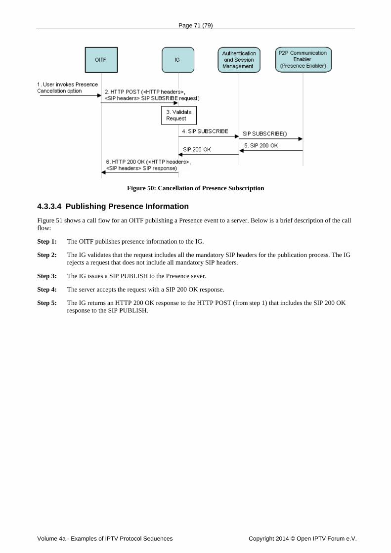
Page 71 (79)
Volume 4a - Examples of IPTV Protocol Sequences Copyright 2014 © Open IPTV Forum e.V.
Figure 50: Cancellation of Presence Subscription
4.3.3.4 Publishing Presence Information Figure 51 shows a call flow for an OITF publishing a Presence event to a server. Below is a brief description of the call flow:
Step 1: The OITF publishes presence information to the IG.
Step 2: The IG validates that the request includes all the mandatory SIP headers for the publication process. The IG rejects a request that does not include all mandatory SIP headers.
Step 3: The IG issues a SIP PUBLISH to the Presence sever.
Step 4: The server accepts the request with a SIP 200 OK response.
Step 5: The IG returns an HTTP 200 OK response to the HTTP POST (from step 1) that includes the SIP 200 OK response to the SIP PUBLISH.

Page 72 (79)
Volume 4a - Examples of IPTV Protocol Sequences Copyright 2014 © Open IPTV Forum e.V.
OITF
SIP: PUBLISH ()
3. SIP PUBLISH
4. 200 OK
IG
1. HTTP Post (<HTTP Headers>, <SIP headers>-SIP PUBLISH Request)
2. Validate Request
5. HTTP 200 OK (<HTTP Headers>, <SIP headers>- SIP Response)
P2PCommunication
Enabler(Presence Enabler)
Authenticationand SessionManagement
200 OK
Figure 51: Publishing a Presence Event
4.3.4 Content Sharing
4.3.4.1 Content Sharing Capability Query Figure 52 shows a call flow for an OITF initiating content sharing and firstly the recipient capability should be queried. Below is a brief description of the call flow:
Step 1: The user invokes the content sharing option on the OITF.
Step 2: The OITF issues a HTTP POST request to the IG including the SIP OPTIONS requested headers.
Step 3: The IG validates the request and generate the SIP OPTIONS by mapping the receiving headers to the appropriate SIP headers.
Step 4: The IG issues a SIP OPTIONS to the Content Sharing function to forward the message to recipient. The recipient completes authority checking and responds with appropriate capability information.
Step 5: The Content Sharing function receives the response from recipient and returns a SIP 200 OK response with capability.
Step 6: The IG returns an HTTP 200 OK response to the HTTP POST that includes the SIP 200 OK response to the SIP OPTIONS.

Page 73 (79)
Volume 4a - Examples of IPTV Protocol Sequences Copyright 2014 © Open IPTV Forum e.V.
OITF
IG Authentication
and Session Management
P2P Communication Enabler(Content
Sharing)
3. validate Request
4. SIP OPTIONS
SIP OPTIONS
200 OK (SDP)
200 OK (SDP)6. HTTP 200 OK(<HTTP Headers>,<SIP headers>
SIP Response)
1. user invoke Content sharing option
2. HTTP Post(<HTTP Headers>,<SIP headers> SIP OPTIONS Request)
ITF
SIP OPTIONS
5. 200 OK (SDP)
Figure 52: Content Sharing Capability call flow
4.3.4.2 Content Sharing session origination, session modification and session termination
Step 1: The user invokes the content sharing option on the OITF. The sharing content could be multimedia content including pictures, video, etc.
Step 2: The OITF issues a HTTP POST request to the IG including the SIP INVITE requested headers.
Step 3: The IG validates the request and generate the SIP INVITE by mapping the receiving headers to the appropriate SIP headers.
Step 4: The IG issues a SIP INVITE to the Content Sharing function including user id for recipient authentication, content list for recipient choosing from, and related SDP.
Step 5: The Content Sharing function receives the response from recipient ITF and returns a SIP 200 OK response with SDP.
Step 6: The IG returns an HTTP 200 OK response to the HTTP POST that includes the SIP 200 OK response to the SIP INVITE
Step 7: Upon receipt of a 200 OK response, the OITF SHALL send an HTTP PENDING_IG to acknowledge the final response.
Step 8: Upon successful session setup, the RTP media starts.
Step 9: During the content sharing, the recipient can modify the content sharing session by sending a SIP Re-INVITE to the network. In the Re-INVITE request, SDP will indicate “sendonly” or “inactive” etc depending on the reason for the session modification. Examples of events that can lead to session modification include bandwidth changes, putting the ongoing session on hold, sharing of a new content by any peer, etc.
Note that the ongoing session should be put on hold prior to performing session modification
Step 10: IG issues a HTTP 200 OK response to the HTTP POST that includes the SIP Re-INVITE.
Step 11: The OITF returns HTTP POST request to the IG including the SIP 200 OK to report the response to the SIP Re-INVITE.

Page 74 (79)
Volume 4a - Examples of IPTV Protocol Sequences Copyright 2014 © Open IPTV Forum e.V.
Step 12: When the IG receives the response, the IG SHALL return the SIP 200 OK response.
Step 13: The OITF issues a HTTP POST request to the IG including the SIP BYE requested headers to terminate the content sharing session.
Step 14: The IG validates the request and generate the SIP BYE by mapping the receiving headers to the appropriate SIP headers.
Step 15: The IG issues a SIP BYE to the Content Sharing function for content sharing function to forward it to ITF.
Step 16: The Content Sharing function receives the response from recipient ITF and returns a SIP 200 OK response.
Step 17: The IG returns an HTTP 200 OK response to the HTTP POST that includes the SIP 200 OK response to the SIP BYE.
OITF
IG
Authentication and Session Management
1. user invoke Content sharing option
2. HTTP Post(<HTTP Headers>,<SIP headers> SIP
INVITE, SDP)
3. validate Request
4. SIP INVITE (user id, content list, content id, SDP)
5. 200 OK
200 OK6. HTTP 200 OK(<HTTP Headers>,<SIP headers> SIP Response)
SIP INVITE
7. HTTP Pending
11.HTTP Post(<HTTP Headers>, <SIP headers> SIP 200 OK, SDP)
P2P Communication Enabler(Content
Sharing)
10. HTTP 200 OK(<HTTP Headers>,<SIP headers> SIP Re-
INVITE, SDP)
Re-INVITE (SDP)
200 OK
12. 200 OK
9. Re-INVITE (SDP)
Recipient modify the content sharing session
ITF
SIP INVITE
200 OK
8. Content transmission (RTP)
Re-INVITE (SDP)
200 OK
Display to user
Voice call session
13. HTTP Post(<HTTP Headers>,<SIP headers> SIP
BYE, SDP)
14. validate Request
15. SIP BYE
SIP BYE
SIP BYE
16. 200 OK
200 OK 17. HTTP 200 OK(<HTTP
Headers>,<SIP headers> SIP Response)
200 OK
Figure 53: Content Sharing session initiation, modification and terminaion

Page 75 (79)
Volume 4a - Examples of IPTV Protocol Sequences Copyright 2014 © Open IPTV Forum e.V.
4.3.4.3 OITF transferring a Content Sharing session Step 1: During the content sharing, the recipient can transfer the content sharing session to other terminal. When the
content sharing session is in conjunction with a voice call, the transferring of this multimedia session of content sharing will have no impact to voice call session. The ITF1 as transferor sends request to the Content Sharing function. The Content Sharing function issues a SIP REFER request to IG.
Step 2: IG issues a HTTP 200 OK response to the HTTP POST that includes the SIP REFER. The SIP REFER includes the transferee id, service id, SDP etc.
Step 3: The OITF validates the request including the security checking and IMS Content Sharing service identifier etc. The OITF recognized the transfer request is to transfer the multimedia session according to the service identifier. The OITF should send HTTP Pending message.
Step 4: The OITF issues an HTTP PENDING_IG request in anticipation of any incoming messages.
Step 5: After validates the request, the OITF issues an HTTP POST request including SIP 202 Accept.
Step 6: IG issues a SIP 202 Accept response to the transferor OITF to report the received response from the remote OITF to the transfer request.
Step 7: OITF issues a HTTP POST request to the IG including the SIP INVITE requested headers to ITF2 as transferee.
Step 8: The IG received the request from the OITF SHALL generate the SIP INVITE by mapping the receiving headers to the appropriate SIP headers and forward it to ITF2.
Step 9: The ITF2 returns a SIP 200 OK response with SDP to Content Sharing function and Content Sharing function forward it to IG.
Step 10: IG issues a HTTP 200 OK response to the HTTP POST that includes the SIP 200 OK.
Step 11: The OITF issues a HTTP POST request to the IG including the SIP NOTIFY requested headers to ITF1.
Step 12: The IG received the request from the OITF reporting the outcome of the session transfer, SHALL generate the SIP NOTIFY by mapping the receiving headers to the appropriate SIP headers and forward it to the transferor OITF.
Step 13: At some point in time, the Content Sharing function received a SIP 200 OK response from ITF1 and forward it to IG.
Step 14: IG issues a HTTP 200 OK response to OITF including the SIP 200 OK response. The session between ITF1 and OITF tears down.
Step 15: The content sharing service is streaming between OITF and ITF2.

Page 76 (79)
Volume 4a - Examples of IPTV Protocol Sequences Copyright 2014 © Open IPTV Forum e.V.
OITF
IG
Authentication and Session Management
3. validate Request
202 Accept6. 202 Accept
14. HTTP 200 OK(<HTTP Headers>, <SIP headers> SIP NOTIFY,SDP)
4. HTTP Pending
P2P Communication Enabler(Content
Sharing)
12. SIP NOTIFY (SDP)
2. HTTP 200 OK(<HTTP Headers>, <SIP headers> SIP REFER)
5. HTTP Post (<HTTP Headers>, <SIP headers> 202 Accept)- Pending Request
11. HTTP Post(<HTTP Headers>, <SIP headers> SIP NOTIFY,SDP)
SIP NOTIFY (SDP)
13. 200 OK
200 OK
ITF1
ITF2
1. SIP REFER (transferee id, service id, SDP)
SIP REFER
SIP REFER
7. HTTP Post(<HTTP Headers>, <SIP headers> SIP INVITE (SDP)
8. SIP INVITE
SP INVITE
SIP INVITE
200 OK10. HTTP 200 OK(<HTTP Headers>,<SIP headers> SIP Response)
200 OK9. 200 OK
Ongoing content sharing session
202 Accept
15. content sharing between OITF and ITF2
Figure 54: Content Sharing session transfer
4.4 Content Preparation
4.4.1 Encryption sequences Content is encrypted by the Encryption Function. The encrypted content is made available to the Content Delivery Network and the corresponding content key can be used by the CSP servers when generating license for the content.
CSP-T / CSP-G Server
CoD Encryption Function/ Scheduled Content Encryption Function
Storage / CDN
CSP-T / CSP-G Server
Content Mgt Function/
Scheduling Function
1.2: request
response including drmSignaling
Key Management Function
1: CreateEncodingJob()
1.1: request
response including scheduledKey (incl. keyId and key) and
drmSignaling 1.3: publish()
IPTV Applications
2.1: get license()
NPI-45 / NPI-46 NPI-CSPT3 / NPI-CSPG3
Figure 55: Multi-DRM main workflows

Page 77 (79)
Volume 4a - Examples of IPTV Protocol Sequences Copyright 2014 © Open IPTV Forum e.V.
The Key Management Function is called by the Encryption Function to get or set the key that has to be used to encrypt the content (NPI-45/NPI-46).
Upon reception of this key request, the Key Management Function:
• generates the keys and an identifier (keyId) for this content if not provided by the Encryption Function,
• stores keys and identifiers,
• requests each CSP server to return the drmSignaling information that have to be inserted in the section dedicated to each DRM in the stream and/or side metadata (NPI-CSPT3/NPI-CSPG3),
• returns key, keyId (if not provided by the Encryption Function) and the drmSignaling to the Encryption Function (NPI-45/NPI-46).
The Encryption Function encrypts the content with the provided key and updates the stream metadata using the provided keyId and drmSignaling.
The encrypted content and the corresponding signaling (e.g MPD in case of DASH) are published on the Content Delivery Network or stored (UNIT-17/NPI-44).
4.4.1.1 Content on Demand Figure describes the simplest case where content on demand (CoD) is encrypted. In this case the Key Management Function simply assigns one keyId/key to the content.
CSP-T / CSP-G Server
CoD Encryption Function Storage
CSP-T / CSP-G Server
Content Mgt Function Key Management Function
1.3: publish(manifest, encryptedContent)
1.1: GetKeyScheduleSignaling(contentId, encryptionProfile, drmInfo, pregenerationWindow):contentKey with keyId and key, timeReference, drmSignaling
1.2: SetKeyScheduleAndGetSignaling(encryptionProfile, drmInfo, scheduledKey): drmSignaling
1: CreateEncodingJob(contentId, list of drmSystemId):status
Figure 56: Encrypt Content on Demand
The encrypting job is launched by the Content Management Function (NPI-49) which provides a contentId and the list of DRM used to protect the content.
The Key Management Function assigns key and keyId to the content and retrieves the drmSignaling that is to be inserted in the stream signaling from each concerned CSP Server (NPI-CSPT3/NPI-CSPG3). This information is returned to the CoD Encryption Function that uses it to encrypt the content (NPI-45).
Note: keyId/key pair may also be generated by the Encryption Function and provisioned to the Key Management Function. But in this case the system is not able to pre-generate licenses (to generate licenses before the corresponding content key is actually used to encrypt the content) if keys are not provided to the Key Management Function ahead of time.
4.4.1.2 Scheduled content with periodic key rotation controlled by the Key Management Function
Figure describes the case where keys are rotated on scheduled content. The key rotation is controlled by the Key Management Function.

Page 78 (79)
Volume 4a - Examples of IPTV Protocol Sequences Copyright 2014 © Open IPTV Forum e.V.
CSP-T / CSP-G Server
Scheduled Content Encryption Function CDN
CSP-T / CSP-G Server
Scheduling Function Key Management Function
1: ConfigureLive(contentID, list of drmSystemId)
1.1: GetKeyScheduleSignaling(contentId, encryptionProfile, drmInfo, pregenerationWindow):contentKey with keyId and key, timeReference, drmSignaling
1.2: SetKeyScheduleAndGetSignaling(encryptionProfile, drmInfo, scheduledKey): drmSignaling
1.3: publish(manifest, encryptedContent)
On time basis, decides if a new key is to be issued or if the earlier key can still be used
Loop periodic querying from the Encryption Function
Loop for every fragment
Figure 57: Encrypt scheduled content with periodic key rotation controlled by the Key Management Function
On a regular basis the Scheduled Content Encryption Function requests keys to the Key Management Function for each scheduled content service (NPI-46). The keys have to be queried at a higher frequency than the key rotation period (e.g. every 10 minutes if the keys are changed every day).
• The Key Management Function assigns a key to the corresponding service for the time provided by the Scheduled Content Encryption Function.
• The Key Management Function manages the schedule for key changes for scheduled content services. It means that it maintains a list of keys associated with time. The keys are typically rotated once a day (e.g. during the night).
The Key Management Function centralizes all the information required to generate the drmSignaling to be included e.g. in DASH MPD and/or pssh box. This information is returned to the Scheduled Content Encryption Function which inserts it in the stream (NPI-46).
4.4.1.3 Scheduled content with periodic key rotation controlled by the Scheduled Content Encryption Function
Figure describes the case where keys are rotated on scheduled content. The key rotation is controlled by the Scheduled Content Encryption Function.
CSP-T / CSP-G Server
Scheduled Content Encryption Function CDN
CSP-T / CSP-G Server
Scheduling Function Key Management Function
1: ConfigureLive(contentID, list of drmSystemId)
1.1: SetKeyScheduleAndGetSignaling(encryptionProfile, drmInfo, scheduledKey): drmSignaling
1.2: SetKeyScheduleAndGetSignaling(encryptionProfile, drmInfo, scheduledKey): drmSignaling
1.3: publish(manifest, encryptedContent)
Loop at every key rotation
Loop for every fragment
Figure 58: Encrypt scheduled content with periodic key rotation controlled by Scheduled Content Encryption Function
Key change periodicity is configured in the Scheduled Content Encryption Function. The Scheduled Content Encryption Function has to provision the keys in the Key Management Function before they are actually used (NPI-46).
• The Scheduled Content Encryption Function manages the schedule for key changes for scheduled content services. It means that it maintains a list of keys associated with time. The keys are typically rotated once a day (e.g. during the night).
• The Scheduled Content Encryption Function provisions these keys in the Key Management Function which stores this information (NPI-46).

Page 79 (79)
Volume 4a - Examples of IPTV Protocol Sequences Copyright 2014 © Open IPTV Forum e.V.
The Key Management Function centralizes all the information required to generate the drmSignaling to be included e.g. in DASH MPD and/or pssh box. This information is returned to the Scheduled Content Encryption Function which inserts it in the stream (NPI-46).
4.4.1.4 Scheduled content with event based key rotation Figure describes the case where some events on scheduled content are protected by a dedicated key (e.g. to be sold as Pay-per-view or with different parental rating level).
CSP-T / CSP-G Server
Scheduled Content Encryption Function CDN
CSP-T / CSP-G Server
Scheduling Function Key Management Function
1: SetLiveSchedule(list of contentID, period, drmMetadata)
1.1: SetKeyScheduleAndGetSignaling(encryptionProfile, drmInfo, scheduledKey): drmSignaling
1.2: SetKeyScheduleAndGetSignaling(encryptionProfile, drmInfo, scheduledKey): drmSignaling
1.3: publish(manifest, encryptedContent)
Loop for every event
Loop for every fragment
Figure 59: Encrypt scheduled content with event based key rotation
• The Scheduling Function provides a schedule of events to the Scheduled Content Encryption Function (NPI-53).
• The Scheduled Content Encryption Function requests a key to the Key Management Function for each event that is identified by its own contentId (NPI-46).
• The Key Management Function assigns a keyId/key to the corresponding event (identified by its contentId).
• The Key Management Function centralizes all the information required to generate the drmSignaling to be included e.g. in DASH MPD and/or pssh box. This information is returned to the Scheduled Content Encryption Function which inserts it in the stream (NPI-46).
Keys assigned to the channel (and not an event on this channel) can still be periodically changed as described in scheduled content with periodic key rotation.
Note: keyId/key pair can also be generated by the Scheduled Content Encryption Function and provisioned to the Key Management Function. But in this case the system is not able to pre-generate licenses (to generate licenses before the corresponding content key is actually used to encrypt the content) if keys are not provided to the Key Management Function ahead of time.