oklahoma department of environmental quality · oklahoma department of environmental quality ... by...
TRANSCRIPT

OKLAHOMA DEPARTMENT OF ENVIRONMENTAL QUALITY
AIR QUALITY DIVISION
MEMORANDUM May 23, 2008
TO: Phillip Fielder, P.E., Permits & Engineering Group Manager, Air Quality
THROUGH: Kendal Stegmann, Senior Environmental Manager, Compliance and
Enforcement
THROUGH: Jian Yue, P.E., Engineering Section
THROUGH: David Schutz, P.E., New Source Permits Section
THROUGH: Peer Review
FROM: Phillip Martin, P.E., Engineering Section
SUBJECT: Evaluation of Permit Application No. 98-014-C (M-14) PSD
Sunoco, Inc. (R&M) (Sunoco)
Tulsa Refinery
Sunoco Diesel Upgrade Project
1700 South Union
Tulsa, Tulsa County, OK
Latitude 36.138, Longitude 96.009 W
SECTION I. INTRODUCTION
Sunoco Incorporated (Sunoco) owns and operates a petroleum refinery (SIC 2911, NAICS
32411) in Tulsa, Oklahoma (the Tulsa Refinery). The facility is currently operating under Permit
No. 98-014-TV issued on May 30, 2006 and modifications 98-014-TV (M-8), 98-014-TV (M-9),
and 98-014-TV (M-10). The refinery is a Title V major source and is located in an area
designated as attainment for all criteria air pollutants. The refinery is an existing major source
for the Federal Prevention of Significant Deterioration (PSD) program and a Maximum
Achievable Control Technology (MACT) source category regulated under 40 CFR Part 63,
Subpart CC (MACT I) and Subpart UUU (MACT II).
Sunoco is proposing to construct a diesel hydrotreating unit (DHT) for the production of ultra
low sulfur diesel (ULSD). Sunoco expects to start construction upon receipt of this permit and
commission the project by first quarter of 2010. The objective of the project is to provide
facilities to produce ULSD at the Tulsa Refinery. This project will construct a diesel
hydrotreater, amine fuel gas contactor and amine regenerator, Claus sulfur recovery unit with
associated tail gas treater and incinerator, and a sour water stripper. Each of these processes is
an integral part of the Diesel Upgrade Project. The Diesel Upgrade Project will result in a net
emissions increase for NOx that is greater than the PSD Significant Emission Rate (SER) for
PERMIT MEMORANDUM 98-014-C (M-14) PSD
2
NOx. Therefore, the project is subject to PSD review. No other regulated air pollutant is emitted
in significant amounts to require PSD review.
The ULSD project is being installed to meet U.S. EPA standards for sulfur concentration in
highway diesel fuel. On January 21, 2001, the U.S. EPA published the Heavy-Duty Engine and
Vehicle Standards and Highway Diesel Fuel Sulfur Control Requirements rule that required
refiners to lower the sulfur content in diesel from 500 parts per million (ppmw) to 15 ppmw by
June 1, 2006. The refinery currently only produces off-road diesel with high sulfur content.
SECTION II. PROJECT SUMMARY
Sunoco is proposing to construct a DHT for the production of ULSD. The refinery does not
currently hydrotreat diesel. This project will construct a new 32,000-barrel per day (bpd), 1,200-
psig hydroprocessing facility to desulfurize diesel boiling range distillate streams to ULSD
standards. The design ULSD sulfur specification is 15 ppmw.
The hydrotreated diesel from the DHT unit will be processed through a new diesel stripper
column where hydrogen sulfide (H2S) gas and light hydrocarbons (HCs) will be stripped from
the diesel. The ULSD recovered from the column bottom will be directed to product tankage for
shipping.
The stripper offgas will be directed to a new Amine Treatment Unit (ATU) downstream of the
stripper where the sour offgas will be sweetened to NSPS-grade refinery fuel gas (RFG). The
sour gas will contain H2S and will be directed to a new sulfur recovery unit (SRU) where the H2S
gas will be reduced to water and elemental sulfur. The offgas from the SRU will be routed to a
tail-gas treatment unit (TGTU) for further recovery of sour gases. The sour gases from the
TGTU will be circulated back into the SRU for further processing. The TGTU exhaust will be
directed to a gas-fired incinerator for final destruction.
Two new combustion sources and existing boilers will be utilized to provide steam and heat
requirements for the new process line. The sweetened RFG recovered from the ATU will be
used as fuel in the new combustion units and several other existing combustion sources.
The majority of the DHT feedstocks will come from different intermediate cuts from the existing
refinery. Additional feed material may be purchased from other refineries. The purchased
feedstocks will be received by truck, rail, or pipeline. The overall DHT throughput will impact
some of the downstream processing units, including storage and transportation operations at the
refinery. Two new storage tanks will be constructed as part of the Diesel Upgrade Project, one
to store amine and the second for sour water storage.
Sunoco is also subject to a Consent Decree entered in the U.S. District Court for the Eastern
District of Pennsylvania on June 16, 2005, which requires the refinery to undertake certain
emission reduction actions.

PERMIT MEMORANDUM 98-014-C (M-14) PSD
3
PSD Applicability
Emissions decreases resulting from compliance with the Consent Decree are not creditable for
PSD netting purposes, except for 250 TPY of SO2 in total for all of the Sunoco refineries as
specified in the Consent Decree. The issuance of this permit will retire the SO2 Consent Decree
credits in total and they may not be used at any other Sunoco refinery.
As summarized in Table II-1, emissions attributable to projects not related to the Consent Decree
that are included in this permit exceed PSD significance levels for NOx. These projects, when
combined with other planned and completed projects in the contemporaneous netting period,
show that only NOX is above the PSD SER. Therefore, the proposed changes are subject to PSD
permitting requirements for NOx only. The PSD review for this permit also requires an air
quality analysis to estimate the ambient impacts of emissions from the project (OAC 252:100-8-
35). A full PSD analysis including an air quality analysis is presented in Section V of this
memorandum.
Table II-1. Net Emissions Increase For PSD Regulated Pollutants
Pollutant Emission Rate,
TPY
PSD Significant
Emission Rate, TPY
Subject to
PSD Review?
CO 63.01 100 No
PM10 13.45 15 No
NOX 121.77 40 Yes
SO2 2.81 40 No
VOC 25.88 40 No
BACT
As part of the PSD review process, a Best Available Control Technology (BACT) analysis is
required for each pollutant that is emitted in excess of its PSD SER. The BACT analysis is
based on the most effective technology currently available, with consideration for energy,
environmental, and economic factors. The results of the BACT analysis form the basis for the
selection of control technology and the resulting emission limitations for each emissions unit.
The BACT analyses for the new emissions units for this project are summarized in Table II-2. A
detailed discussion of the BACT analyses is given in Section V of this memorandum.
Table II-2. Summary of Proposed BACT
EQUIPMENT POLLUTANT BACT DESCRIPTION
Process Heaters NOx Ultra-Low NOX burners, 0.03 lb/MMBtu
SRU Combustion Units NOx Good Combustion Practice, 0.14 lb/MMBtu

PERMIT MEMORANDUM 98-014-C (M-14) PSD
4
SECTION III. DESCRIPTION OF PROCESSES
Sunoco’s crude is received by pipeline and tanker truck. The crude is a mixture of purchased
crude oils from various sources, which, when blended, has the required properties to make the
lubricating oil products. Sunoco currently is operated primarily to produce high quality
lubricating oils. Refinery fuel gases, propane, butane, isobutane, normal butane, gasoline,
kerosene, No. 2 fuel oil, paraffin wax, petroleum coke, and Lube Extracted Feedstock (LEF) are
some of the current byproducts from making the lube oils. LEF is a mixture of unfinished
streams that may also be transferred to third party purchasers.
The specific types of refining process and support facilities in current use in the Sunoco Refinery
are discussed in the following paragraphs. All of the process units and associated support
equipment at Sunoco operate as a whole (one primary operating scenario). Individual units or
pieces of equipment undergo periodic scheduled periods of shutdown for maintenance, but no
one unit or piece of equipment has any permit restrictions on potential operating hours.
Therefore, total potential operating hours per year for all equipment is 24 hours per day, seven
days per week, for every day of the year.
The new processes from this project are listed first, then the processes with associated emissions,
and then existing processes that are not affected by this project.
NEW PROCESSES
DIESEL HYDROTREATING UNITS (84 – DHT)
The DHT will consist of a standard, single cold separator design unit. The heart of the process is
a fixed-bed catalyst. At high pressure, hydrogen reacts with sulfur present in the feed to form
H2S. Additional hydrogen is consumed in the reactor from the partial saturation of aromatics in
the feed and the complete saturation of olefins present in the feed. The majority of the energy
required to heat the feed stream in order to initiate the desulfurization reaction will be provided
by recovery of the heat of reaction in a series of feed-effluent exchangers.
An additional amount of feed preheat will be provided by a 44.0 MMBtu/hr charge heater. The
charge heater will be fired with sweetened RFG recovered from the new ATU. Reaction
hydrogen will be provided exclusively from existing semi-regeneration reformer (#2 Platformer).
The hydrogen will be compressed to the required reaction pressure by an electric-powered
reciprocating gas compressor.
The hydrotreated diesel from the DHT unit will be processed in a new fractionation column
where H2S gas and light HCs will be stripped from the diesel. The stripper column will have a
53.7 MMBtu/hr process heater, and stripping steam will be used for vapor lift.
In addition to ULSD, the catalytic reaction in the DHT will produce 2,600 bpd of naphtha that
must be returned to the refinery’s existing crude atmospheric column for further processing. The
DHT naphtha will contain 103 lb/hr of sulfur in the form of hydrogen sulfide (110 lb/hr H2S).
Essentially all of the incremental H2S from the DHT naphtha will exit the top of the atmospheric
column and will be distributed into 3 streams: T-4 Crude Unit Stabilizer; V-205 Light Ends

PERMIT MEMORANDUM 98-014-C (M-14) PSD
5
Recovery Unit (LERU) Unit DeEthanzier; and V-207 LERU Unit DePropanizer (Liquid Propane
& Butane). Sour gas from the first two towers currently feed the refinery sour fuel gas system,
while H2S in the DePropanizer stream is scrubbed with potassium hydroxide (KOH) to convert
the sulfur to K2S salt, which is shipped offsite for disposal. After this project, the sour gas from
the first two towers will be treated by the ATU.
AMINE TREATMENT UNIT (85 – ATU)
The stripper offgas and recycle purge gas will be directed to a new ATU downstream of the
stripper. The ATU consists of an amine contactor and amine regenerator. The process removes
H2S from acid gas and hydrocarbon streams. The acid contaminants are absorbed by counter
flowing amine solution (methyl diethanol amine - MDEA) in the contactor. The stripped gas is
removed overhead, and the amine is sent to the regenerator. In the regenerator, the acidic
components are stripped by heat and reboiling action and then processed in the SRU. The amine
is recycled back to the contactor.
A stripper will remove H2S from the rich amine, using steam as the heating medium.
The ATU treated gas will comply with NSPS Subpart J or Subpart Ja when it is promulgated. It
will be routed to a new fuel gas drum equipped with an H2S continuous emission monitoring
device (CEM). A portion of the amine-treated refinery fuel gas (RFG) will be used as fuel for
the diesel hydrotreater and sulfur process units; a portion will be used as fuel in existing reformer
heaters (PH-5 and PH-6), and the remaining will be sent to the existing sour fuel gas distribution
system. The sour gas from the amine contactor and the regenerator will be routed to the SRU for
elemental sulfur recovery.
SOUR WATER STRIPPER (86 – SWS)
The proposed project will construct a 100 gallon per minute (gpm) Sour Water Stripper (SWS).
The feed to the SWS is the new sour water from the DHT unit, and primarily water from the
product steam stripping column overhead system. The product is stripped water that is fed to the
desalters as wash water, with excess water being sent to the new API separator. The SWS will
be reboiled by steam. Some of the steam will be generated by the SRU waste heat boiler, and the
balance will come from the refinery “let down” steam.
The SWS acid gas will be routed to the SRU for recovery of the elemental sulfur and destruction
of the ammonia. Oil recovered from the sour water flash drum and the sour water storage tank
will be pumped to the existing refinery slop system for processing.
SULFUR RECOVERY AND TAILGAS TREATMENT UNITS (87 – SRU/TGTU)
The project will construct a SRU with a design capacity of 20.1 long tons per day (LTPD) and
associated TGTU. The feed to the SRU/TGTU will be acid gases from the ATU and the SWS.
The product from the SRU/TGTU is molten sulfur. The SRU will use standard Claus catalyst in
the reactors. Offgas from the SRU will be routed to the TGTU which will use standard
hydrotreating catalyst for the hydrogenation reaction.
The reduced gases from the TGTU will be circulated back to the SRU for elemental sulfur
recovery. The tail-gas treatment and recirculation back to the SRU will guarantee sulfur

PERMIT MEMORANDUM 98-014-C (M-14) PSD
6
recovery efficiency of at least 99.8%. Offgas from the TGTU will be oxidized to SO2 in an
integrated natural gas-fired incinerator. The SRU/TGTU exhaust will be vented into the
atmosphere through a common stack (ST-301).
ASSOCIATED UNITS
Cooling Water
A total cooling water demand of 6,000 gpm will be required by the Diesel Upgrade Project. The
facility’s existing cooling water infrastructure will be modified to accommodate the additional
cooling water needs. Therefore, a new cell with mist eliminators will be included as part of the
Diesel Upgrade Project.
Pressure Relief/Overpressure Control Valves
The pressure relief valves (PRV) and overpressure control valves from the diesel hydrotreater
and sulfur processing units will be connected to the existing Coker flare. Flaring will only occur
during upset or malfunction conditions.
Process Steam
The proposed project will have a net continuous process steam demand during normal operation.
There will also be periodic demands for winterization steam and furnace purge steam (snuffing
steam).
Storage and Loadout
The Diesel Upgrade Project will use existing storage tanks and loading racks to handle the
ULSD product.
Treating the DHT Naphtha Stream
The new DHT will produce 2,600 bpd of naphtha containing 103 lb/hr of sulfur in the form of
hydrogen sulfide (110 lb/hr H2S). This additional naphtha from the DHT must be further
processed in the existing crude unit’s atmospheric column, resulting in incremental H2S exiting
the top of the atmospheric column. The H2S and other light hydrocarbons such as propane from
the top of the column are further treated at:
1. T-4 Crude Unit Stabilizer
2. V-205 LERU Unit DeEthanzier
3. V-207 LERU Unit DePropanizer (Liquid Propane & Butane).
The H2S remaining in the V-207 LERU DePropanizer overhead and bottoms will be scrubbed
with KOH. The sulfur reacts with the KOH to form K2S salt which is disposed of. The offgas
from the T-4 Crude Unit Stabilizer and the V-205 LERU Unit DeEthanizer are currently routed
to the existing refinery sour fuel gas system.
Sunoco proposes to remove the incremental H2S from the Stabilizer offgas and the DeEthanizer
offgas by treating these streams in the new ATU. Routing the Stabilizer and DeEthanizer gas
streams to the amine treating unit not only removes the incremental H2S produced by the DHT
naphtha, but removes H2S from the existing base refinery operations as well. Sunoco estimates

PERMIT MEMORANDUM 98-014-C (M-14) PSD
7
that 912 tons of SO2 emissions from burning refinery fuel gas in existing units will be reduced
annually. By treating these off gas streams Sunoco is greatly reducing SO2 emissions from
combustion units fired by the refinery sour gas system.
It should be noted that processing the DHT naphtha in the crude unit atmospheric column does
not increase energy needed by the process. The naphtha is added to the top pump around loop
and acts as cooling reflux in place of ordinary water-cooled pump around reflux. Therefore there
is no additional fired duty required by introducing the DHT naphtha into the column.
EXISTING PROCESSES
CRUDE DISTILLATION
The Crude Distillation Unit is the first process and is used to separate crude oil or mixtures of
crude and other purchased crude fractions into specific boiling-range streams suitable either for
further processing in downstream units or in some cases, for direct sale after mild treating or
blending. The primary equipment associated with this operation is a main atmospheric pressure
fractionator, a light ends fractionator called the “stabilizer tower,” and two in-series vacuum
distillation units. The atmospheric tower recovers streams that boil at approximately
atmospheric pressure. The stabilizer tower feeds overhead gas to the crude tower and, at high
pressure, effects a first separation of true gases (which go to the refinery fuel gas system) from
crude gasoline. The vacuum towers recover high boiling point fractions that can be recovered
only by lowering the pressure and operating at elevated temperatures. The energy for the
distillation steps is provided by a main crude heater and two vacuum charge heaters, all gas fired.
Other equipment important to crude and vacuum distillation is an extensive heat exchange
system, a crude desalter system, and a vacuum producing system.
LIGHT ENDS RECOVERY UNIT (LERU)
The light gases from the Crude Unit Stabilizer are processed in a deethanizer tower and a
depropanizer tower in the LERU. The deethanizer is a high-pressure fractionator that separates
ethane and lighter fuel gases from propane and heavier hydrocarbons. The depropanizer tower is
a pressurized tower that fractionates deethanizer bottoms into a liquid propane stream and a
liquid mixed butane/pentane stream. The propane is treated with KOH for sulfur removal, stored
in tankage, and sold as commercial liquefied petroleum gas (LPG). The mixed butane/pentane
from the depropanizer is stored in pressurized storage prior to further fractionation. Energy for
the LERU process is provided by steam passing through reboilers (heat exchangers).
ISOMERIZATION UNIT TOWERS
The isomerization reactors are shut down, but an associated fractionation system for separating
manufactured and natural isobutane from normal butane remains in operation. Feed is the LERU
butane/pentane stream from storage. The butane/pentane is brought from storage and treated
with potassium hydroxide for sulfur removal and fed to the deisobutanizer which first creates a
propane/isobutane feed for a depropanizer that separates propane as an overhead stream from
isobutane as a bottoms stream. The propane is stored and sold as LPG. The isobutane is stored
in a pressurized tank and sold as isobutane. Deisobutanizer bottoms are fed to a debutanizer for
recovery of normal-butane as an overhead product (to sales or to gasoline blending), and pentane
bottoms which goes to gasoline blending.
PERMIT MEMORANDUM 98-014-C (M-14) PSD
8
DEPENTANIZER AND NAPHTHA SPLITTER
The Crude Unit Stabilizer tower bottoms charge the fraction tower called the de-pentanizer. This
de-pentanizer makes an overhead liquid stream called light straight run gasoline which goes to
gasoline blending. Bottoms, called naphtha, are split via level control with part going to the
Unifiner and part to Lube Extracted Feedstock (LEF) that is later shipped to the Sunoco Toledo
Refinery or other third party purchasers. Splitter bottoms join crude naphtha as feed to the
downstream Unifiner Unit. Energy for the de-pentanizer is supplied by a gas fired heater.
UNIFINER
The Unifiner Unit has the purpose of treating naphtha from the Crude Unit and the depentanizer
bottoms in preparation for conversion to high-octane gasoline in the downstream No. 2
Platformer Unit. The Unifiner includes a hydrogen-treating reactor that removes sulfur and other
contaminants that would be detrimental to the downstream Platformer. Other major equipment
includes a hydrogen compressor, gas/liquid reactor effluent separator vessels, a stripper column
to remove gases from the reactor product, and heat exchange systems. Two gas-fired heaters
supply energy for the reactors and stripper column.
NO. 2 PLATFORMER
Unifiner effluent charges the Platformer, which catalytically converts the low-octane paraffin
hydrocarbons to high-octane aromatics for gasoline blending. Naphtha feed is preheated by heat
exchange, charged to a series of four endothermic catalytic reactors (four gas-fired heaters
supply the heat of reaction), flashed to separate gas from product, and distilled through a
debutanizer tower. The debutanizer is energized by a gas-fired reboiler heater. Hydrogen and
other light gases are by-products that are primarily sent to refinery fuel gas, although a hydrogen-
rich stream is used to provide hydrogen to the Unifiner reactors and the lube hydrotreater.
DEASPHALTER
The Deasphalter Unit processes heavy bottoms from the second stage vacuum tower at the Crude
Unit. Two parallel solvent extraction towers mix feed and propane solvent and produce two
streams, one that is paraffinic and suitable as feedstock for lube manufacture in the downstream
Lube Extraction Unit, and a second that is asphaltic that charges the Coker Unit. Some of the
paraffin stream is also blended to the lube-extracted feedstock that is exported by pipeline to the
Sunoco Toledo Refinery or third party purchasers. The Deasphalter Unit employs other towers,
vessels, pumps, heat exchangers, etc., to recover propane solvent from the product streams.
Propane is recycled to the front-end extraction towers. Two gas fired process heaters and steam
from the refinery system provide energy for the extraction process and for solvent recovery
operations.
LUBE OIL EXTRACTION AND HYDROGENATION
This unit is charged with vacuum gas oil fractions and paraffinic deasphalted oil which flows
into two parallel counter-current solvent extraction towers that utilize furfural as a solvent. As a
result, two streams are produced, a waxy paraffinic stream suitable for lube oil manufacture and
an aromatic stream that is either blended with lube oil extracted feedstock for pipeline shipment
to the Sunoco Toledo Refinery or sold as extract product. The waxy paraffinic stream is fed to a
hydrogenation unit to improve its stability and remove impurities before going to a downstream
dewaxing operation. The hydrotreater is a fixed bed catalytic unit that uses hydrogen from the

PERMIT MEMORANDUM 98-014-C (M-14) PSD
9
No. 2 Platformer. The unit employs towers, vessels, heat exchangers, pumps, etc., to remove and
recycle the furfural solvent from the product streams. Three gas-fired heaters provide energy for
the process.
MEK DEWAXING UNIT
This unit removes wax from the hydrotreatred paraffins from the Lube Extraction Unit. The
process employs two solvents in mixture, toluene and methyl-ethyl-ketone. Fabric filters on
rotating drums are used to physically separate wax from oil. A propane refrigeration system
provides cooling to effect wax precipitation out of oil/wax solutions. Paraffin streams are fed in
blocked out batches (the boiling range of the various batches having been set when recovered as
separate streams at the Crude Unit vacuum towers). The separated oil is stored and used for
finished lube oil blending. The separated wax is stored and sold as various melt point products.
Waxes with a melt point above about 116 °F are further processed through a downstream
Percolation Filtration Unit. The unit equipment includes oil/solvent contactors, rotating drum
fabric filters, towers and vessels for solvent recovery and recycle, a propane refrigeration
compressor system, a flue gas compressor system associated with the fabric filters, pumps, heat
exchangers, etc. Two gas fired process heaters are employed, one for oil/solvent separation, and
one for soft wax/solvent separation.
WAX PERCOLATION FILTRATION UNIT
This unit produces several grades of wax but no longer produces food grade waxes. Tanks,
LDAR components and one gas fired heater are the only processes operational in this unit.
COKER UNIT
Sunoco’s Coker Unit produces solid coke in a batch process. The Coker Unit equipment list
includes two gas fired process heaters, two coke drums, a main fractionator, and other towers,
vessels, pumps, heat exchangers, etc. The Coker Unit alternates the process between two vessels
called drums. One drum is being charged for processing while the other is being emptied or “de-
headed.” The process begins by charging one of the coke drums with the asphaltic stream from
the Deasphalting Unit. The process thermally separates the heavy molecules into carbon (coke)
and light hydrocarbons. The charge is heated to 900 F using two gas-fired process heaters and
then is allowed to have residence time while the coke and the light hydrocarbons separate. The
light hydrocarbons flows/charges the product fractionation system (a part of the Coker Unit) for
separation into gas for refinery fuel, and liquids which are pipelined to the Sunoco Toledo
Refinery or to third party purchasers, and gasoline for recovery back through the Crude Unit
stabilizer. After a drum is de-headed the coke is cut using high pressure steam and the drum is
cleaned out with steam for the next batch. Coke is stored in piles on-site, for bulk shipment by
rail or trucks. Air emissions from handling the finished coke are insignificant.
LUBE/WAX BLENDING AND SALES/SERVICE OPERATIONS
This refinery’s primary purpose is to produce finished paraffinic lubricating oils. These waxes
are also an important by-product of lube oil manufacturing process. To provide the specialty
products required by Sunoco’s diverse customers, there is a product blending and shipping
operation at the site. The blending primarily occurs in fixed cone roof tank areas. Packaging
and package storage is conducted in the Lube Service Center building. Shipment is by bulk in
tank trucks and tank railcars.

PERMIT MEMORANDUM 98-014-C (M-14) PSD
10
STEAM GENERATION
In an area called “No. 5 Boilerhouse” (No. 4 Boilerhouse was dismantled in the 1970s), there are
seven gas-fired boilers that produce steam for general refinery use. There are five individual
boiler units numbered Nos. 3, 4, 7, 8, and 9. Boilers No. 1 and 2 have been shut down,
generating NOx credits. In addition to the steam generated by these boilers, steam will be
produced from one or two temporary boiler(s). One temporary boiler is in place with startup
expected in Feb 2008.
WASTEWATER TREATMENT
Facility wastewaters are conveyed in combined storm/process sewers, through oil/water
separators and to a treatment area that employs storm surge capacity, clarification, dissolved air
floatation, equalization, and aerobic waste digestion. Treated water is discharged to the
Arkansas River. Recovered sludges and oil are separated at a centrifuge facility and the oil is fed
to the Coker Unit or Crude Unit.
COOLING TOWERS
The refinery employs 7 non-contact cooling towers. These are systems that circulate captive
waters that provide a heat sink for various process units or equipment. Water is circulated
through heat exchangers to indirectly cool hydrocarbon or other streams. Hot water from these
exchangers is collected by pipelines and sprayed over packed towers in counter current flow to
atmospheric air. The evaporation of a portion of the hot (typically 100 to 120 F) circulated
water provides cooling to about 85 F (summer) for recirculation back to the heat exchangers.
The white plumes observed from these towers are the evaporated water that sometimes re-
condenses cloud-like at certain atmospheric conditions. The cooling towers have not used
chrome-based systems since before 1994, are not subject to NESHAP MACT Subpart Q, and are
trivial sources named in Appendix J of OAC 252:100.
FLARE STACKS
The refinery employs four vertical, piloted flare stacks for the emergency containment and
combustion of certain hydrocarbon releases. Various equipment at Sunoco are fitted with
pressure relief valves to protect against overpressure conditions. These pressure relief valve
outlets discharge into a gas collection flare piping system. Each flare stack uses a continuous
pilot light that assures ignition of any gaseous discharges. Each flare also uses a steam system
that supplies a constant source of steam for mixing with the gas being flared (as needed) to
reduce/prevent the combustion products from smoking.
LOGISTICS AND STORAGE
The Sunoco logistics system involves feed and product receipt and shipment systems, as well as
extensive internal movements. Crude feed material is primarily received by pipeline into large
tanks. Product shipments are also made by pipeline, tank truck, rail tank car, and package truck
trailer. This refinery does not have a marine terminal. There is an extensive storage tank system
that handles crude feeds, finished products, and process intermediates. Types of material are
generally in common geographical areas, but there are many exceptions due to the long history
of the site.

PERMIT MEMORANDUM 98-014-C (M-14) PSD
11
SULFUR AND OTHER IMPURITY TREATMENTS
This refinery processes feeds that are low in sulfur content and does not employ a FCCU. This
project will install the first large hydrotreater, amine gas scrubber, sour water stripper, and
elemental sulfur recovery unit at this refinery. Refinery process offgases often contain
significant amounts of sulfur. These offgases flow to a RFG system and can be burned only in
grandfathered fuel-burning units. Refined product sulfur impurities are addressed within specific
process units by caustic or chemical treatment steps.
SECTION IV. PROJECT EMISSIONS
The Tulsa Refinery is an existing PSD major source. This section presents the emission
calculation methodology used to determine PSD applicability for the new, modified, and
associated units, including process heaters, SRU unit, equipment leaks, cooling towers, storage
tanks, and emissions associated with increased steam production.
A PSD Netting analysis was performed based on suggested emissions netting procedures in the
Draft Environmental Protection Agency (U.S. EPA) New Source Review (NSR) Workshop
Manual. A six-step procedure was used for determining the net emissions change:
1. Emissions Increases from the Project (PSD Applicability) - Determine the emission increases
from the project from any new sources, modified sources, and associated sources (i.e.
debottlenecked units). If increases are above PSD Significant Emission Rates (SERs),
proceed, if not, the project is not subject to PSD review.
2. Contemporaneous Period - Determine the beginning and ending dates of the
contemporaneous period as it relates to the project.
3. Emissions Increases and Decreases During the Contemporaneous Period - Determine which
emissions units at the facility experienced or will experience a creditable increase or decrease
in emissions during the contemporaneous period. This step also includes any emissions
decreases from the project.
4. Creditable Emissions Changes - Determine which contemporaneous emissions changes are
creditable.
5. Amount of Emissions Increase and Decrease - Determine, on a pollutant-by-pollutant basis,
the amount of each contemporaneous and creditable emissions increase and decrease.
6. PSD Review Applicability - Sum all contemporaneous and creditable increases and decreases
with the emissions changes from the project to determine if a significant net emissions
increase will occur.
The following sections detail each of the steps outlined above.
Step 1. Emissions Increases from the Project (PSD Applicability)
The maximum potential emissions from each new, modified, and associated source were
determined for this project. For each PSD pollutant, the baseline actual emissions are subtracted
from the potential emissions to determine the emissions increase for each new, modified, or
associated source. Baseline actual emissions are defined in OAC 252:100-8-31 as “the average

PERMIT MEMORANDUM 98-014-C (M-14) PSD
12
rate in tons per year at which the unit actually emitted the pollutant during any consecutive 24-
month period selected by the owner or operator within the 10-year period immediately preceding
the date a complete application is received.” For new emissions sources the baseline actual
emissions are zero. For this project, Sunoco averaged emissions from the 2005 and 2006
emission inventories to determine baseline actual emissions for each pollutant from a given
source. Emission decreases are not considered in this step. The emissions increases for each new,
modified, and associated source are shown in the following sections.
Process Heaters
1. Emissions Increases Used for Both PSD Applicability and PSD Netting
Two new heaters will be installed as part of the DHT project. The heaters will be fired with
sweetened RFG recovered from the new ATU. The heaters will be equipped with Ultra-Low
NOX burners (ULNB). Hourly values of VOC, PM10, and CO have been increased by 50% to
allow for periods of startup and shutdown.
TABLE IV-1A. PROCESS HEATER EMISSIONS RATES
Process Heaters
Emissions NOx VOC PM10 CO SO2
MMBtu/hr lb/ MMBtu TPY lb/hr TPY lb/hr TPY lb/hr TPY lb/
MMBtu TPY
DHT Heater (B4101) 44.0 0.03 5.78 0.43 1.25 0.59 1.72 6.52 19.05 0.03 2.42 DHT Heater (B4102) 53.7 0.03 7.06 0.53 1.52 0.72 2.10 7.96 23.24 0.03 2.95
Totals - 12.84 0.96 2.77 1.31 3.83 14.48 42.29 - 5.36
The emissions are based on the following factors and continuous operation.
TABLE IV-1B. PROCESS HEATER EMISSIONS FACTORS
Contaminant Emission Factor
w/ Safety Factor Unit Basis
Emission
Factor Unit
NOx (new unit) 0.03 lb/MMBtu Manufacturer Guarantee
VOC 0.0065 lb/MMBtu AP-42 + 20% safety factor 5.5 lb/MMscf
PM10 0.0089 lb/MMBtu AP-42 + 20% safety factor 7.6 lb/MMscf
CO 0.0988 lb/MMBtu AP-42 + 20% safety factor 84 lb/MMscf
SO2 0.013 lb/MMBtu Site-specific factor
Associated Boilers
Associated emissions increases for boilers are included in this permit application for the purpose
of verifying PSD applicability and air quality modeling. The boilers are included as a result of an
incremental increase in steam demand due to the DHT project. The project does not involve
physical modifications to any associated emission units. These emission units will continue to
operate in compliance with currently applicable rules, regulations, and permit conditions.

PERMIT MEMORANDUM 98-014-C (M-14) PSD
13
Therefore, this permit does not include emission limits, or specific conditions for the associated
emission units.
TABLE IV-2. BOILER EMISSIONS INCREASE
Boiler incremental
increase due to increased
steam demand from
Boiler House
Emissions (TPY)
NOx VOC PM/PM10 CO SO2
Energy Increase 59.31 1.16 1.61 17.79 191.95
The emissions are based on the worst case emission factors (280 lb NOx/MMSCF and a site
specific factor for SO2 of 1.11 lb/MMBtu) for the least efficient boilers (No. 3 & 4) to produce
the incremental steam.
Sulfur Recovery Unit (SRU) / Tail Gas Treatment Unit (TGTU)
A new SRU/TGTU will be installed as part of the DHT project. The SRU/TGTU will be fired
with sweetened RFG recovered from the new ATU.
TABLE IV-3A. SRU/TGTU EMISSIONS RATES
SRU Emissions NOx VOC PM10 CO SO2
lb/MMBtu TPY lb/hr TPY lb/hr TPY lb/hr TPY ppmv TPY SRU Unit 0.14 4.4 2.41 7.03 1.62 4.73 1.00 2.93 250 15.93
The emissions are based on the following factors and continuous operation.
TABLE IV-3B. SRU/TGTU EMISSIONS FACTORS
Contaminant Emission Factor Unit Source
NOx 0.14 lb/MMBtu Fuel fired basis - Incinerator burner vendor estimate
VOC 18.60 lb/MMscf stack gas Incinerator burner vendor estimate of (ppm) 160
PM/PM10 0.15 lb/MMBtu Fuel fired basis - Incinerator burner vendor estimate
CO 7.75 lb/MMscf stack gas Incinerator burner vendor estimate of (ppm) 105
SO2 42.17 lb/MMscf stack gas NSPS maximum allowable of (ppm) 250
H2S 0.90 lb/MMscf stack gas NSPS maximum allowable of (ppm) 10
Tanks
Two new tanks will be constructed as part of the DHT project. One will be an IFRT sour water
tank and the other a FRT amine tank. The sour water contains H2S and NH3.

PERMIT MEMORANDUM 98-014-C (M-14) PSD
14
TABLE IV-4A. NEW TANK EMISSIONS RATES
Tanks Emissions (TPY)
VOC H2S
Sour Water TK21T-014 - 0.09
Amine TK85T-614 - -
There will be an increase in throughput of existing distillate tanks. The following table shows the
total increase from new and existing tanks.
TABLE IV-4B. EXISTING TANK EMISSIONS INCREASE
Tanks Emissions (TPY)
NOx VOC1 PM/PM10 CO SO2 H2S
Total - 4.08 - - - - 1 Emission estimates were generated through Tanks4.0.9d. This program contains default chemical properties for
petroleum distillates, crude oils and organic liquids. From the Petroleum Distillate category, distillate fuel oil no. 2
was selected to represent the properties of distillates, sour water and amine tank contents. Estimated emissions are
conservatively high as the anticipated vapor pressures of stored material are less than Tanks4.0.9d's default diesel
VPs.
Cooling Towers
Modifications to one existing cooling tower are included in the proposed project. Cooling Tower
#9 (Butane Splitter CT) will receive a new cell with a capacity of 6,000 GPM. Emission
calculations for total dissolved solids (TDS) concentration (5,000 parts per million [ppmw]) and
drift rate (0.005%) are based on current design information. Emissions for VOC are calculated
using the controlled emission factor for petroleum refinery cooling towers presented in AP-42
(9/91) Table 5.1-2. Emission calculations are presented in Tables IV-5A and IV-5B.
TABLE IV-5A. COOLING TOWER PM10 EMISSIONS INCREASE
Emissions
Unit
TDS,
ppmw
Drift
Rate, %
Recirculation
Rate, gpm
PM10,
lb/hr
PM10,
TPY
Past Actual,
TPY
Net,
TPY
Cooling
Tower #9 5,000 0.005 6,000 0.75 3.29 0.0 3.29
TABLE IV-5B. COOLING TOWER VOC EMISSIONS INCREASE
Emissions
Unit
Recirculation
Rate, gpm
Emission
Factor,
lb/106 gallon
VOC,
lb/hr
VOC,
TPY
Past Actual,
TPY
Net,
TPY
Cooling
Tower #9 6,000 0.7 0.25 1.10 0.0 1.10

PERMIT MEMORANDUM 98-014-C (M-14) PSD
15
Equipment Fugitives
The proposed project will result in an increase in VOC emissions from equipment leaks due to
the installation of equipment such as flanges, valves, compressors, pressure relief valves, and
pumps. The emissions increases for equipment leaks are calculated using design-basis
component counts along with emission factors that were developed specifically for the Tulsa
Refinery based on the LDAR testing for 2005 and 2006 and the protocol in EPA Document EPA-
453/R-95-017, November 1995, Protocol for Equipment Leak Emission Estimates. Drain emission
factors are assumed to be equal to the compressor/other factor. The factors and emissions of
VOC and H2S are given in the following table.
TABLE IV-6A. LDAR EMISSIONS RATES
Components Added
Number of
Components
Emission
Factors,
lb/hr-source
VOC,
TPY
H2S, TPY
VOC / H2S
GGG Components Added:
Valves 2,399 / 460 0.0004 4.61 0.88
Flanges / Connectors 6,445 / 138 0.0001 3.73 0.08
Pumps 9 / 32 0.0003 0.01 0.05
Compressors / Others (Including
Sampling Connections)
27 / 7 0.0014 0.09 0.04
Pressure Relief Valves to Flare 1 15 / 28 0.0006 0.04 0.07
QQQ Components Added:
Others (Including Process Drains) 128/69 0.0014 0.78 0.42
Overall Net Emissions Change 9.26 1.54 1 The flare control efficiency is assumed to be 98%.
Loading Emissions
There will be an increase in throughput of existing truck and rail car loading. The following table
shows the total increase from truck and rail car loading.
TABLE IV-7. LOADING EMISSIONS RATES
Incremental
Increase from
Loading
Emissions (TPY)
NOx VOC PM/PM10 CO SO2
All Loading - 0.48 - - -
Emissions Increases Summary
The following table summarizes the project emissions increases for all new and associated
sources that will be used for PSD Applicability.

PERMIT MEMORANDUM 98-014-C (M-14) PSD
16
TABLE IV-8. PROJECT SUMMARY EMISSIONS RATES
Source NOx VOC PM/PM10 CO SO2 H2S
lb/hr TPY lb/hr TPY lb/hr TPY lb/hr TPY lb/hr TPY lb/hr TPY
Process Heaters 2.93 12.84 0.63 2.77 0.87 3.83 9.66 42.29 1.22 5.36 NA NA
Steam & Energy Increase 13.54 59.31 0.27 1.16 0.37 1.61 4.06 17.79 43.82 191.95 NA NA
SRU Impact 1.0 4.4 1.60 7.03 1.08 4.73 0.67 2.93 3.64 15.93 0.00 0.34
Tanks NA NA 0.93 4.08 NA NA NA NA NA NA 0.02 0.09
Fugitive (LDAR) NA NA 2.11 9.26 NA NA NA NA NA NA 0.35 1.54
Cooling Tower NA NA 0.25 1.10 0.75 3.29 NA NA NA NA NA NA
Loading NA NA 0.11 0.48 NA NA NA NA NA NA NA NA
TOTALS NA 76.55 NA 25.88 NA 13.45 NA 63.01 NA 213.24 NA 1.97
PSD Applicability
The following table shows the total applicable emission increase for each PSD regulated
pollutant. The total project emission increase for each pollutant is compared to the PSD SER for
that pollutant to determine if a PSD netting analysis is required. As shown in the table the
emission increase for NOx and SO2 is above the SER. Therefore, a PSD netting analyses, based
on steps 2 through 6 of the PSD netting procedure, is required for NOx and SO2.
TABLE IV-9. PROJECT EMISSION INCREASE FOR PSD REGULATED POLLUTANTS
Pollutant Emission
Rate, TPY
PSD Significant
Emission Rate, TPY
PSD Netting
Analysis Required?
NOX 76.55 40 Yes
SO2 213.24 40 Yes
CO 63.01 100 No
VOC 25.88 40 No
PM10 13.45 15 No
Step 2. Contemporaneous Period
According to OAC 252:100-8-31, “an increase or decrease in actual emissions is
contemporaneous with the increase from the particular change only if it occurs within 3 years
before the date that the increase from the particular change occurs”. DEQ has interpreted the
contemporaneous period to be three years prior to the start of construction through the start of
operation. Therefore, for this project, the contemporaneous period begins May 1, 2005 and ends
at startup of operations.
Step 3. Emissions Increases and Decreases During the Contemporaneous Period
Contemporaneous emissions increases and decreases are those emissions associated with new
construction, a physical change, or change in the method of operation of a source that begins
operation during the contemporaneous period. Contemporaneous emissions decreases are those
emissions decreases associated with new construction, a physical change, change in the method

PERMIT MEMORANDUM 98-014-C (M-14) PSD
17
of operation of a source, or reductions in actual emissions from a federally-enforceable emission
limit that begin operation during the contemporaneous period.
Project-Related and Consent Decree-Related Emission Decreases
Sunoco proposes to remove the H2S from the Stabilizer offgas and the DeEthanizer offgas by
treating these streams in the new Amine Treating Unit. Routing the Stabilizer and DeEthanizer
gas streams to the amine treating unit not only removes the H2S from the existing base refinery
operations, but removes the incremental H2S produced by the DHT naphtha as well. Sunoco
estimates that 912 tons of SO2 emissions from burning refinery fuel gas will be reduced annually,
but the Consent Decree only allows credit for a 250 TPY reduction of SO2.
Other Contemporaneous Emission Increases and Decreases
There was one project to add two temporary boilers (M-12) and one project to change the
number of burners in an existing heater (M-13) during the contemporaneous period. The (M-12)
project added 31.22 TPY of NOx and 0.57 TPY of SO2. The (M-13) project added 14 TPY of
NOx and 39 TPY of SO2.
Step 4. Creditable Emissions Changes
A contemporaneous increase or decrease is creditable only if the DEQ has not relied upon it in
previously issuing a PSD permit. In addition, the PSD permit must be in effect when the
emissions increase or decrease from the proposed modification occurs. For pollutants with PSD
increments, a contemporaneous increase or decrease in actual emissions which occurs before the
baseline date in an area is creditable only if the increase or decrease would be considered in
calculating how much of an increment remains available for the pollutant in question. A
contemporaneous decrease is creditable only to the extent that it is federally enforceable from the
moment that construction begins on the project with the contemporaneous emissions decrease. A
source cannot take credit for a contemporaneous decrease that it has had to make, or will have to
make, in order to bring an emissions unit into compliance. Furthermore, a source cannot take
credit for an emission reduction of potential emissions from an emissions unit that was
permitted, but never built or operated.
This is the first PSD permit for the Sunoco Tulsa Refinery. There have been three minor
modification permits applied for in the contemporaneous period but none have been issued yet.
One was an administrative amendment with no change in emissions. The other two projects
have been included in the PSD netting.
Step 5. Amount of Emissions Increase and Decrease
The Consent Decree allows a credit for up to 250 TPY reduction of SO2. The (M-12) project
added 31.22 TPY of NOx and 0.57 TPY of SO2. The (M-13) project added 14.0 TPY of NOx
and 39.0 TPY of SO2 based on the conservative approach of the difference of the potential to
emit and the baseline actual emissions.

PERMIT MEMORANDUM 98-014-C (M-14) PSD
18
Step 6. PSD Review Applicability
The following table summarizes the significant net emissions increase for each significant PSD
pollutant for this project and the contemporaneous period.
TABLE IV-10. SIGNIFICANT NET EMISSIONS INCREASES
Pollutant
Emission
Increase,
TPY
Creditable
Contemporaneous
Emissions, TPY
Net
Emission
Increase,
TPY
PSD Significant
Emission Rate,
TPY
Subject to
PSD
Review?
NOX 76.55 31.22 + 14 121.77 40 Yes
SO2 213.24 -250 + 0.57 + 39 2.81 40 No
The project is subject to PSD review for each regulated pollutant for which the sum of all
creditable emissions increases and decreases results in a significant net emission increase.
Additional prospective and creditable emission reductions sufficient to provide for a less than
significant net emission increase at the source may be proposed to avoid PSD review. As shown
in Table IV-10, a PSD review is not required for SO2. Emissions of NOx require a full PSD
review. The PSD review for NOx is presented in Section V.
SECTION V. PSD Review for Pollutant NOx
A full PSD review consists of the following steps:
1. Determination of BACT.
2. Analysis of air quality impacts. This analysis includes:
Description of dispersion model and procedures
Determination of air quality impact significance
Determination of pre-construction monitoring requirements
Compliance with National Ambient Air Quality Standards (NAAQS)
Compliance with available PSD increments
3. Evaluation of source-related impacts on growth, soils, vegetation, and visibility.
4. Evaluation of Class I Area impacts.
In addition, the proposed project is subject to certain federal and state standards including, but
not limited to, NSPS 40 CFR Part 60, Subparts A, J, GGG, and QQQ, and NESHAP 40 CFR
Part 63, Subpart CC (MACT I), and Subpart UUU (MACT II). NESHAP Subpart DDDDD has
been vacated and USEPA is currently revising this regulation. Sunoco will be compliant with
the final NESHAP DDDDD when promulgated.
1. Determination of BACT
OAC 252:100-8-1.1 defines BACT as “...the control technology to be applied for a major source
or modification is the best that is available as determined by the Director on a case-by-case
basis taking into account energy, environmental, and economic impacts and other costs of
alternate control systems.”
PERMIT MEMORANDUM 98-014-C (M-14) PSD
19
A BACT analysis is required to assess the appropriate level of control for each new or physically
modified emissions unit for each pollutant that exceeds the applicable PSD SER. As shown in
Section IV, only net emissions of NOx exceed the PSD SER.
The U.S. EPA has stated its preference for a “top-down” approach for determining BACT and
that is the methodology used for this permit review. After determining whether any New Source
Performance Standard (NSPS) is applicable, the first step in this approach is to determine, for the
emission unit in question, the available control technologies, including the most stringent control
technology, for a similar or identical source or source category. If any of the control
technologies are technically infeasible for the emission unit in question, that control technology
is eliminated from consideration. The remaining control technologies are then ranked by
effectiveness and evaluated based on energy, environmental, and economic impacts beginning
with the most stringent remaining technology. If it can be shown that this level of control should
not be selected based on energy, environmental, or economic impacts, then the next most
stringent level of control is evaluated. This process continues until the BACT level under
consideration cannot be eliminated by any energy, environmental, or economic concerns. The
five basic steps of a top-down BACT review are summarized as follows:
Step 1. Identify Available Control Technologies
Step 2. Eliminate Technically Infeasible Options
Step 3. Rank Remaining Control Technologies by Control Effectiveness
Step 4. Evaluation of Remaining Control Technologies Based on Energy, Environmental,
and Economic impacts
Step 5. Select BACT and Document the Selection as BACT
The U.S. EPA has consistently interpreted statutory and regulatory BACT definitions as
containing two core requirements that the agency believes must be met by any BACT
determination, regardless of whether it is conducted in a “top-down” manner. First, the BACT
analysis must include consideration of the most stringent available control technologies, i.e.,
those that provide the maximum degree of emissions reduction. Second, any decision to require
a lesser degree of emissions reduction must be justified by an objective analysis of energy,
environmental, and economic impacts.
The new NOx emission sources for this project are:
A. Process heaters B4101 and B4102.
B. SRU Combustion Unit.
These BACT evaluations are based on the following resources:
Engineering experience;
EPA’s RACT/BACT/LAER Clearinghouse database search;
EPA’s “Alternate Control Techniques Document for NOX Emissions” June 1994, and
EPA’s Air Pollution Technology Fact Sheets.

PERMIT MEMORANDUM 98-014-C (M-14) PSD
20
The RACT/BACT/LAER Clearinghouse (RBLC), a database made available to the public
through the U.S. EPA’s Office of Air Quality Planning and Standards (OAQPS) Technology
Transfer Network (TTN), lists technologies that have been approved in PSD permits as BACT
for numerous types of process units. Process units in the database are grouped into categories by
industry.
NOx Emissions
NOx emissions are generated from the high temperature dissociation of atmospheric nitrogen
molecules and their subsequent reaction with oxygen to form nitrogen monoxide (NO) or
nitrogen dioxide (NO2) (thermal NOx) and from chemically bound nitrogen in the fuel (fuel
NOx). Thermal NOX is primarily formed at temperatures above 1,300oC; therefore, limiting the
temperature of the flame can control its generation. Fuel NOX is formed when the fuel nitrogen
is converted to hydrogen cyanide and then oxidized to form NO that further oxidizes in the
atmosphere to NO2. Since the first step of the oxidation occurs in the combustion chamber,
providing an oxygen-deficient atmosphere in the combustion chamber can significantly reduce
NO, and thereby NO2 formation.
Some combustion processes can be modified to minimize NOX emissions by reducing:
peak flame temperature;
gas residence time in the flame zone; and
oxygen concentration in the flame zone.
The RACT/BACT/LAER Clearinghouse (RBLC) database contains information from early
notification submittals and air permits received from various state and local air pollution control
programs in the United States. The data assist companies in determining what types of controls
and pollution prevention measures have been applied to and/or are required for various sources
and the effectiveness of these technologies. The permit application provided results for the
lowest emission rates for NOx (0.03 lb/MMBtu). These results were obtained from the EPA’s
RBLC database for the similar categories combustion units.
Step 1. Identify Available Control Technologies
To comply with the “top-down” process for the BACT analysis, the following subsection
contains a technology-by-technology evaluation starting with the most stringent control option.
These various technologies are discussed in detail under the evaluation for the process heaters
and are not repeated for the rest of the evaluated units.
BACT for Process Heaters with Heat Rate of 44.0 MMBtu/hr and 53.7 MMBtu/hr
The proposed Diesel Upgrade Project will install two RFG-fired process heaters with heat input
of 44.0 MMBtu/hr and 53.7 MMBtu/hr respectively. RFG and natural gas are known to have
low fuel-bound nitrogen level. Therefore, the primary focus of this evaluation is the reduction of
thermal NOX.

PERMIT MEMORANDUM 98-014-C (M-14) PSD
21
The following paragraphs discuss possible thermal NOx control technologies in decreasing order
of control efficiencies.
Selective Catalytic Reduction (SCR)
An SCR system utilizes the abilities of certain compounds, most commonly urea or ammonia, to
react with NOx emissions, to form benign chemical compositions. A controlled amount of the
reactive chemical is sprayed into the exhaust stack, and is met by an intricate arrangement of
precious metals which act as catalysts for the chemical reaction. Historically, SCRs have been
very successful NOx control devices. The drawbacks of SCRs are that they tend to have high
capital costs, and the process heater exhaust stream must meet certain temperature and pressure
values for the device to function properly.
Past examples indicate that SCRs have achieved significant NOx reductions for natural gas and
RFG-fired process heaters. At optimum operating conditions, NOx reductions of approximately
90% are likely to be realized by the installation of an SCR system. The efficiency and final
emissions rates are very difficult to predict as they depend on the SCR unit and the pressure and
temperature achieved in the stack. Based on data found in the RBLC, it is predicted that the SCR
will achieve approximately 85% NOx reductions. Although the ammonia feed rates in SCR
systems are designed to minimize any release of ammonia, most manufacturers specify an
ammonia slip rate between 2 and 10 ppmv.
Selective Non-Catalytic Reduction
Selective Non-Catalytic Reduction (SNCR) was also reviewed for potential application to the
proposed process heaters. SNCR requires excellent flue gas to ammonia (urea) mixing ratio
which requires large combustion chamber volumes and residence time. This technology also
requires a precise and stable temperature window in the boiler at which to inject the ammonia or
urea.
The process heaters are factory-packaged units with relatively small combustion chamber. The
process heaters do not have adequate room in their combustion chambers to provide the required
flue gas-to-ammonia mixing ratio for effective performance of the SNCR. Although the heaters
will operate the equivalent of 8,760 hours per year, they will serve a broad range of process
duties. The likely sporadic operation with load following over a turndown range will create wide
firing and temperature distribution variations within the combustion chamber that is inherently
too small for ammonia and NOx to effectively contact each other. This will preclude the ability
to utilize SNCR for NOx control in these units.
SNCR is therefore determined to be not technically feasible for application to the proposed RFG-
fired process heaters.
Low-NOX Burners with Flue Gas Recirculation
The use of low-NOX burners is a widely accepted method to control NOX emissions from
combustion sources. Low-NOX burners are developed by burner and boiler manufacturers and

PERMIT MEMORANDUM 98-014-C (M-14) PSD
22
therefore exhibit a wide variety of designs. However; the principle for all NOX burners is the
same: the burners inherently generate lower NOX emissions due to internal staging of fuel
combustion. Burner staging delays combustion and reduces the peak flame temperature, thus
reducing thermal NOX formation. High levels of excess air within the primary combustion zone
reduce the temperature. Secondary fuel is injected into the combustion zone under high pressure.
This action results in heat being transferred from the first stage combustion products to the
second stage combustion. As a result, the second stage combustion is achieved at lower partial
pressures of oxygen and temperature than would normally be encountered.
Flue gas recirculation (FGR) is a technique in which a portion of exhaust gas or flue gas is
recycled to a point where it joins and, therefore, dilutes the inlet combustion airflow. The
dilution serves to lower peak flame temperature, thus reducing thermal NOX formation.
All identified top-down BACT decisions for similar packaged process heaters conclude that
Ultra-Low NOx Burners (ULNB) represents the best practical and cost effective alternative for
this particular source type. Most ULNB’s sold by the major manufacturers utilize internal
“micro combustion staging”, whereby flue gas is internally recirculated into the highest
temperature portion of the flame, and additional air is added downstream to complete burn out of
products of incomplete combustion. From the RBLC data, the lowest emission rate that can be
achieved when burning RFG with this technology is 0.03 lb NOx / MMBtu.
Staged Firing
Staged firing is a technology that reduces NOX formation by operating outside the normal
stoichiometric ratio; it includes over fire air, burners-out-of-service, and biased firing methods.
Burners Out of Service, Separated Over-fire Air, and Gas Reburn
Various staged combustion techniques have been applied to vertically oriented, field erected
combustion sources, including Burners Out of Service (BOOS) and, Separated Over-fire Air
(SOFA). All of these technologies seek to limit the formation of NOx by vertical combustion
staging in the furnace of field-erected combustion sources, where sufficient volume and
residence time exists to starve the high temperature combustion zone of oxygen, and then adding
the oxygen back to complete combustion in the upper section of the furnace. No listings of
RFG-fired process heaters were found in the RBLC which employ burners out of service,
separated over fire air, or gas reburn technologies for control of NOx. Nor were any of these
technologies discussed in the EPA’s ATC Document as applicable to this type of process heater.
None of these methods of NOx control are determined to be technically feasible for application
to the proposed process heaters.
Step 2. Eliminate Technically Infeasible Options
SNCR can be eliminated as technically infeasible. Therefore, all the rest of the technologies
mentioned above will be examined for energy, environmental, and economic impacts.

PERMIT MEMORANDUM 98-014-C (M-14) PSD
23
Step 3. Ranking of Remaining Control Technologies by Control Effectiveness
The following table lists the technologies identified as possible NOX reduction technologies for
the proposed combustion sources at the Sunoco’s Tulsa facility along with their expected percent
reductions.
TABLE V-1. Possible Control Technologies for NOX Emissions
Control Technology Theoretical NOX Reduction1
Combustion Modifications:
Low-NOX burners and flue gas recirculation 40 – 60%
Air staging 20 - 40%
Post Combustion Modifications:
Selective catalytic reduction (SCR) 80 - 90%
Selective non-catalytic reduction (SNCR) 30 - 50%
NOTE:
1. Theoretical Reduction Efficiencies based on the publication: “Best Achievable Control
Technology for Air Pollution Control: Analysis Guidance and Case Studies for North
America,” by North American Commission of Environmental Corporation. – February 2005
Step 4. Evaluation of Remaining Control Technologies
Selective Catalytic Reduction (SCR)
While an SCR is not normally considered a powered device, it will necessitate slight increase in
energy consumption. Since hardware will be installed directly into the exhaust stack, the exhaust
fans will have to do more work to achieve an appropriate flow rate. Furthermore, the ammonia
sprayers draw small amounts of power as well. Operating an SCR also implies certain indirect
increases in energy consumption, such as the energy required to create and transport ammonia.
From RBLC search, the use of SCR system to control NOx emission from an RFG-fired or
natural gas-fired process heater or any other combustion unit is cost effective when the rated heat
input exceeds 280 MMBtu/hr. Other reviewed air pollution control technology sources were in
agreement with the RBLC results. Therefore, SCR technology is not considered economically
viable for the process heaters.
The remaining control technologies are less effective than ULNB so they are eliminated.
Step 5. Select BACT and Document the Selection as BACT
BACT Selection for the Process Heaters
The 44.0 MMBtu/hr and the 53.7 MMBtu/hr RFG-fired heaters will be equipped with ULNB.
The low NOx emissions for the process heaters (0.03 lb/MMBtu) agrees with the emissions rates

PERMIT MEMORANDUM 98-014-C (M-14) PSD
24
identified in the RBLC search and also are below the EPA’s new source performance standard
for these units. This low NOx emission rate is readily achievable due to the pre-installed ULNB.
Therefore, the selected BACT for the heaters is ULNB at an emission rate of 0.03 lb NOx /
MMBtu (3-hour average).
BACT Evaluation for the SRU Combustion Unit
A SRU will be an integral part of the Diesel Upgrade Project. The SRU unit is equipped with a
natural gas/RFG-fired combustion unit of insignificant heat rating (<10 MMBtu/hr).
Review of the RBLC did not reveal any apparent cost effective control technology for similar
combustion units. A listed company operating a similar combustion unit achieved NOx emission
rate of 1 lb/hr through combustion control and good operating practices. Based on 7.2
MMBtu/hr unit rating, the equivalent emission rate is 0.14 lb/MMBtu. Therefore, a maximum
NOx emission rate of 0.14 lb/MMBtu (3-hour average) is the selected BACT for the SRU
Combustion Unit and will be accomplished by good combustion practices.
Analysis of Air Quality Impacts
The Sunoco Tulsa Refinery is located in Tulsa County, which is currently designated attainment
or unclassified for all criteria pollutants, and there are no areas classified as non-attainment
within 50 kilometers of the refinery. This modification will result in emission increases
sufficient to trigger the PSD requirements codified in 40 CFR Part 52.
PSD is a construction-permitting program designed to ensure air quality does not degrade
beyond the NAAQS or beyond specified incremental amounts above a prescribed baseline level.
The PSD rules set forth a review procedure to determine whether a source will cause or
contribute to a violation of the NAAQS or maximum increment consumption levels. If a source
has the potential to emit a pollutant above the PSD significance levels, then they trigger this
review process. EPA has provided modeling significance levels (MSL) for the PSD review
process to determine whether a source will cause or contribute to a violation of the NAAQS or
consume increment. Air quality impact analyses were conducted to determine if ambient
impacts would be above the EPA defined modeling and monitoring significance levels. If
impacts are above the MLS, a radius of impact (ROI) is defined for the facility for each pollutant
out to the farthest receptor at or above the significance levels. If a radius of impact is established
for a pollutant, then a full impact analysis is required for that pollutant. If the air quality analysis
does not indicate a radius of impact, no further air quality analysis is required for the Class II
area.
Sunoco has prepared an air quality analysis in accordance with the procedures and methodology
presented, which are consistent with guidance provided by the Oklahoma Department of
Environmental Quality (ODEQ) and Environmental Protection Agency (EPA). The results of
this air quality analysis show that the proposed emissions authorized in this permit will not cause
or contribute to an exceedance of the NAAQS or significant PSD increment consumption.

PERMIT MEMORANDUM 98-014-C (M-14) PSD
25
Description of dispersion model and procedures
Sunoco performed an air dispersion modeling analysis for the proposed Diesel Upgrade project
using the AMS/EPA Regulatory Model (AERMOD). AERMOD is an EPA-approved, steady
state Gaussian plume model capable of modeling multiple sources in simple and complex
terrain. AERMOD is the model currently approved for industrial sources and PSD permits, it is
an appropriate model for the facility, and ODEQ requested that Sunoco demonstrate regulatory
compliance through its use.
Potential Emissions and Stack Parameters
The air dispersion modeling evaluated potential emissions of NO2 from new combustion sources,
and incremental increase in steam from existing boilers. NO2 from the incremental increase in
steam utilization is the difference of the projected actual emission to the current actual emission
from worst case boiler. The worst case boiler was assessed based on three criteria: NO2 emission
rates, stack parameters (flowrate, temperature, diameter, etc.), and proximity to the property line.
The boiler stack that presented the worst scenario was selected for the model.
There are several types of emission sources that can be modeled in AERMOD. These source
types include point sources, area sources, and volume sources. The emission sources modeled in
this exercise are point sources, which consist of emission units that release all of their emissions
out of a stack. A summary of the potential emissions and incremental steam requirement from
the proposed facility are presented in the following table along with proposed emission rates and
stack parameters.
TABLE V-2. NO2 Emission Unit Parameters
Parameters
Stack Data
Process Heater
(B4101)
Process
Heater
(B4102)
Incremental
Steam (Existing
Boilers 3 & 4) SRU (ST-301)
UTM Easting (X-m) 768027.42 768027.42 768582.00 767926.70
UTM Northing (Y-m) 4003561.00 4003551.92 4003598.00 4003531.50
Elevation (Z-m) 193.9 193.9 195.07 193
Stack Height (Feet) 90 90 110 150
Stack Temperature (0F) 1,000 860 267.8 1,350
Stack Diameter (Feet) 3.5 4.3 10.5 10.5
Stack Flow rate (acfm) 10,500 13,500 5,0851 1,826.4
NOX (lbs/hr) 1.32 1.61 14.16 1.0
Modeling Methodology
AERMOD model was used to estimate potential air quality impacts from the proposed Diesel
Upgrade project. The modeling analysis described in this report evaluated potential emissions
from the proposed project for compliance with all applicable standards under the PSD

PERMIT MEMORANDUM 98-014-C (M-14) PSD
26
regulations. These standards may be separated into two parts: Class II air quality standards and
Class I air quality standards and related values (AQRVs).
The Class II ambient air quality standards include the NAAQS and the PSD ambient air
increments that apply to all Class II areas in the United States. Class II areas are places that the
air quality is important for the welfare and health of humans, animals, and vegetation. All areas
of the United States, with the exception of Class I areas, are designated as Class II areas.
Class I areas are places that the air quality is of special interest and value. Class I areas include
national parks, wilderness areas, and national forests. Class I area standards include ambient air
increments (similar to those of class II areas, only more stringent) and AQRVs. AQRVs are such
issues as visibility (light extinction) and acid deposition.
The air quality analysis was performed in accordance with the previously submitted PSD
dispersion modeling protocol incorporating the ODEQ comments. The source parameters used in
the preliminary dispersion modeling are summarized in the previous table.
Modeling Applicability
Air dispersion modeling has been performed for NO2 emissions from the proposed project to
compare with applicable annual modeling significance level, Class I significant impact level,
NAAQS, and Class II PSD Increments.
Significance Modeling
To determine whether emissions of a pollutant are required to be modeled for comparison with
the ambient air standards (refined modeling analysis), it must be determined if the emissions
have a significant impact on ambient air quality. Receptor grids used for determining
significance are the same as those used in the refined modeling analysis. If the maximum
modeled off-site concentration is greater than the MSL, the source impact is considered
significant and a refined modeling analysis must be performed. Prior to performing the refined
modeling analysis, a ROI must be established. The ROI is the maximum distance from the
source at which impacts greater than or equal to the applicable MSL are predicted. This ROI is
then used to establish nearby sources that must be included in the refined modeling analysis. The
annual MSL for NO2 is 1.0 μg/m3. A significance modeling analysis was performed and the
results were higher than 1.0 μg/m3 so a refined analysis was performed.
Refined Modeling Analysis
Pollutant emissions for which the proposed facility is considered to have a significant impact on
air quality, must demonstrate that the proposed facility will not cause or significantly contribute
to a violation of the NAAQS. For major PSD sources, the refined modeling analysis must
demonstrate compliance with the NAAQS and PSD increments.
The NAAQS were established by the USEPA under the authority of the Clean Air Act. Primary
NAAQS define levels of air quality that the USEPA deems necessary to protect public health.

PERMIT MEMORANDUM 98-014-C (M-14) PSD
27
Secondary NAAQS define levels of air quality that the EPA judges necessary to protect public
welfare from any known, or anticipated adverse effects of a pollutant. Examples of the public
welfare that are protected by the secondary NAAQS include wildlife, buildings, national
monuments, vegetation, visibility and property values. The USEPA has NAAQS for six criteria
pollutants: PM10, SO2, NO2, CO, ozone, and lead. The USEPA is currently working to implement
a NAAQS for particulate matter less than 2.5 microns in aerodynamic diameter (PM2.5). The
following table lists the NAAQS for NO2.
TABLE V-3. Ambient Air Quality Standards
Pollutant Averaging Period NAAQS (μg/m3)
NO2 Annual 1001
NOTE: 1 Never to be exceeded
A refined modeling analysis was performed to demonstrate that the air emissions from the
proposed new facility do not cause or significantly contribute to a violation of a NAAQS or PSD
increment. In demonstrating compliance with the NAAQS, all nearby significant NO2 emitting
sources (50 kilometers plus ROI) was included to the Sunoco’s new and existing NO2 emitting
sources. To comply with the PSD Increments requirements, all nearby NO2 increment
consuming sources were added to NO2 emissions resulting from the proposed modification. Tier
1 approach was adopted in the PSD increment analysis. Tier 1 approach requires that nearby
PSD increment consuming sources plus emissions from the proposed modification be modeled
using their potential emissions.
Sunoco used a nearby source inventory, provided by ODEQ, that incorporated all sources located
within the ROI + 50 km and that meets the 10-D criteria.
Building Downwash
The modeled emissions from the Sunoco facility were evaluated to determine if the emissions
plume may become entrained in turbulent wakes, thus resulting in potentially higher ambient air
impacts. These wake effects, also known as downwash, are the result of air flowing around large
buildings and structures creating areas, or "zones", of turbulent airflow. The minimum stack
height necessary to avoid downwash effects, known as Good Engineering Practice (GEP) stack
height, is defined by the following equation.
HGEP = H + 1.5L ------------------------------------------------------- (1)
HGEP = GEP stack height
H = Structure or building height
L = the lesser of the structure height or project width
This equation applies only to stacks located within 5L of a downwash structure. Stacks located
more than 5L from the downwash structure are not subject to the wake effects of that structure. If
more than one stack at the facility is modeled, the equation must be successively applied to each

PERMIT MEMORANDUM 98-014-C (M-14) PSD
28
stack. If more than one structure is modeled, the equation must also be successively applied to
each structure. The building downwash determination for this modeling analysis is performed for
each stack and structure using the USEPA-approved Building Profile Input Program for Prime
(BPIPPRM) that is compatible with AERMOD. BPIPPRM will perform the aforementioned
calculation for every 10-degree directional interval starting at 10 degrees and going clockwise to
360 (due North).
GEP Stack Height Determinations
As specified by the USEPA in Appendix W of 40 CFR 51 Section 7.2.5, no stack height credit
may be given in excess of the GEP stack height for any source when determining emission
limitations for compliance with the NAAQS and PSD Increments. As defined in 40 CFR 51.100,
GEP stack height is the greater of 65 meters or the height determined using the equation
discussed in Section 3.4. Some of the stack heights used for the dispersion modeling analysis are
well below 65 meters. Therefore, the emission rates and stack heights used in the modeling
analysis are appropriate for demonstrating compliance with the NAAQS and PSD Increments.
Building downwash has been calculated and included in the dispersion modeling for all stacks.
Modeling Options
The modeling was conducted using the refined model AERMOD (version 07026), with the
following settings:
• regulatory default model parameters, including:
• calm correction
• buoyancy induced dispersion
• stack-tip downwash
• direction specific building downwash
• final plume rise
• default wind profile coefficients
• default vertical potential temperature gradients
• five years of meteorological data (2001 – 2005) pre-qualified by ODEQ consisting
of:
• Surface Air data from Bixby Mesonet Surface Station and the Tulsa/Lloyd Jones
Map (Station ID# 723564), and
• Upper Air from Norman, OK (Station ID # 03948).
Based on land use classifications from United States Geological Survey (USGS) topographical
maps, the majority (i.e., > 50%) of the land surrounding the Tulsa facility can be classified
urban. Therefore, the urban dispersion coefficients were used. Elevated terrain is used in the
modeling analysis to accurately account for the geographical terrain features surrounding the
proposed site. The terrain elevations are established using digital elevation model (DEM) files
from the USGS.

PERMIT MEMORANDUM 98-014-C (M-14) PSD
29
Ambient Air (Fenceline) Boundary
The NAAQS and ambient air increments apply to air that is considered ambient. Ambient air
quality is air outside of buildings that is accessible by the public. In most cases, ambient air
boundaries are delineated based on the location of a fence or other significant physical barrier
that restricts public access. However, in some instances no physical barriers exist and it is
impractical to install such a barrier. Active barriers may be used as a last resort to prevent
public access in these areas. Active barriers are identified as a combination of surveillance,
signs, and security measures that will discourage unauthorized access
Receptor Grid
AERMOD model concentrations may be estimated at discrete receptor locations. The discrete
Cartesian receptor grid is designed to identify maximum predicted impacts due to the proposed
facility. The following receptor systems were used:
A fenceline receptor system with receptors placed along the fenceline at an interval of
50 meters;
A fine Cartesian grid extending 3 kilometers from the site in every direction with
receptors located at an interval distance of 100 meters;
A coarse Cartesian grid extending approximately 7 kilometers from the site with
receptors located at an interval distance of 500 meters, and
Additional coarse Cartesian grid extending approximately 15 kilometers from the site
with receptors located at an interval distance of 1.0 kilometer,
Meteorological and Terrain Data
The dispersion modeling analysis was performed using five years (2001- 2005) of upper and
surface air prequalified meteorological data provided by the ODEQ. The surface air data was
collected at the Bixby Mesonet weather monitoring station and the Tulsa/Lloyd Jones Map, OK
(Station ID# 723564). The upper air data was collected from the Norman University, OK
weather station (Station ID # 03948). Terrain elevations consisting 26 quadrangles of the USGS
7.5 minute Digital Elevation Model (DEM) terrain data were also utilized.
Background Concentrations
The existing ambient air concentrations must be accounted for when demonstrating compliance
with the NAAQS. The existing ambient air concentrations (often referred to as background
concentrations) are often estimated using ambient air monitoring data from the air basin that the
proposed site is located. This method of estimating the background concentration is conservative
because it accounts for the existing air pollutant concentrations (including existing stationary
source impacts). Therefore, refined modeling analyses that use the ambient air monitoring data
as background concentrations are double counting the actual emissions from existing facilities.
For this modeling analysis, the background concentration is estimated based on information

PERMIT MEMORANDUM 98-014-C (M-14) PSD
30
provided by the ODEQ. The background concentration used in this modeling analysis is shown
in the following table.
TABLE V-5. Tulsa NO2 Background Concentration (2006 Annual Mean)
Pollutant Averaging
Period Station ID
Concentration
(μg/m3)
NO2 Annual 401431127
20.7
Nearby Sources
Facilities that must demonstrate compliance with the NAAQS must also include any sources that
are within the ROI plus 50 kilometers, also known as the area of significant influence (ASI). The
ROI is defined as the farthest distance that the modeled facility has an impact equal to or
greater than the applicable MSL. The ROI defined in the preliminary evaluation is
approximately 0.7 kilometers from the facility’s epicenter. Sources within the defined ROI
plus 50 kilometers were included in the modeling.
DISPERSION MODELING RESULTS
Significance Modeling Results
The proposed NO2 emissions were modeled and compared to the MSL. The preliminary analysis
utilized Tier II NO2/NOx ambient ratio method (ARM) listed in Appendix W of the EPA’s
Guideline for Air Quality Model to assess the significant impacts of NO2. The initial modeling
evaluation indicated that the ground level impact is above the NO2 MSL (1.0 μg/m3).
Since the impact from the proposed project is greater than the MSLs for NO2, full impact
modeling was performed that included nearby sources identified by the ODEQ as significant
sources of NO2 for NAAQS and PSD increment consumption. The NAAQS and PSD increments
impacts were evaluated separately. The emissions data used in the NAAQS evaluation includes the
proposed and existing NO2 emission points (PTE basis) at the Sunoco facility and other nearby
significant sources as provided by ODEQ. The PSD increment evaluation was based on potential
emissions from the proposed project plus NO2 emissions from other PSD increment consuming
sources identified by ODEQ within the nearby sources inventory.
The proposed NO2 emissions were modeled and compared to the Class I Significant Impact Level
(SIL). If a significant impact analysis indicates impacts less than the proposed Class I Significant
Impact Level (SIL) of 0.1 μg/m3, then a full Class I increment analysis is not needed. The closest
two Class I areas are Upper Buffalo Wilderness (230 km) and Caney Creek Wilderness (250
km). Given the amount of emissions and the distance to the Class I areas, the source was not
expected to exceed the SIL. Considering the costs and time associated with a CALPUFF impact
analysis, an analysis was first performed utilizing AERMOD (which has an effective range of 50
km). If an AERMOD analysis at 50 km or less indicates impacts less than the SIL, then a
CALPUFF analysis is not necessary. The AERMOD analysis indicated impacts of less than 0.04
μg/m3 (less than half of the SIL) at a distance of 5 km in the directions of Upper Buffalo
Wilderness and Caney Creek Wilderness, the two closest Class I areas. The impacts at Upper

PERMIT MEMORANDUM 98-014-C (M-14) PSD
31
Buffalo Wilderness (230 km) and Caney Creek Wilderness (250 km) would be significantly
below the SIL. Therefore, the proposed source does not cause or contribute to a NOx Class I
increment violation.
TABLE V-6. Summary of Class I Significant Impact Analysis Results for NO2 in μg/m3
Pollutant Averaging Period
Class I Significant
Impact Level
(µg/m3)
Modeled
Concentration 1
(µg/m3)
Comparison to
Class I SIL
(< or >)
NO2 Annual 0.1 0.04 < 1
Concentration at 5 km from the facility.
NAAQS and PSD Increment
As presented in the following tables, the total impacts of NO2 are below the applicable NAAQS
and PSD Increments. The total impacts include the impacts from proposed and existing NO2
emission points at the Sunoco, Tulsa facility and other nearby sources plus existing
background concentration.
TABLE V-7. Summary of Dispersion Modeling Analysis Results for NO2 in μg/m3
Impact on NAAQS:
Pollutant Averaging
Period Year
1
Modeled
Concentration2
Background
Concentration
Total
Concentration NAAQS
NO24
Annual3 2001 73.69 20.7 94.39 100
PSD Increment Consumption:
Pollutant Averaging
Period
Year1 Modeled
Concentration2
Background
Concentration
Total
Concentration
Class II PSD
Allowable
Increment
NO24
Annual3 2001 11.06 NA 11.06 25
NOTES: [1] Year shown is worst case scenario
[2] Includes any nearby source contributions provided by the OK DEQ.
[3] Concentration shown is "high-first-high"
[4] Reported as NO2 using Tier II NO2/NOx ambient ratio method
The above results demonstrate that the proposed Diesel Upgrade project at the Sunoco, Tulsa
Refinery will comply with the NO2 NAAQS, and PSD Increments.

PERMIT MEMORANDUM 98-014-C (M-14) PSD
32
ADDITIONAL IMPACTS ANALYSIS
The additional impact analyses required pursuant to 40 CFR 52.21(o) are:
• Visibility impacts in Class I areas within 300 km
• Visibility impacts in Class II areas
• Impacts on soils and vegetation that would result from the modification
• Impacts on endangered species
• Socioeconomic analysis
The air quality modeling projections performed and presented in the previous Section have
demonstrated that the proposed modification will not cause or contribute to an exceedance of
the applicable National Ambient Air Quality Standard (NAAQS), or PSD Class II increments.
The same can be said for any other anticipated effects that the proposed modification might
have upon the surrounding areas of the Sunoco refinery. Although the source impact analysis
is a quantitative, mathematical determination evaluated in relative numerical terms, other
impact analyses are generally more qualitative and descriptive in nature. The following
sections summarize those additional considerations and demonstrate in each case that the
proposed modification will produce no adverse effects.
Visibility Impact Analysis in Class I Areas
The Clean Air Act Amendments require evaluation of new emission sources to determine
potential impact on visibility in Class I areas. Mandatory Class I areas include international
parks, national wilderness areas, national memorial parks and other areas re-designated to
Class I areas by the state.
There are four Class I areas within 300 km of the refinery, as shown in the following figure. The
closest two Class I areas are Upper Buffalo Wilderness (230 km) and Caney Creek Wilderness
(250 km). Using the screening guidance from the Federal Land Manager (FLM), an assessment
of emissions using the 10D screening indicates that no detailed Class I analysis for visibility will
be required. Specifically, if the sum of annual potential emissions of NOx, PM10, and SO2 is less
than 10D (where D is the distance in km to the Class I area), no detailed analysis is required. The
sum of NO2/SO2/PM10 emissions from the proposed project totals 138.03 TPY [121.77+ 2.81 +
13.45]; the Class I areas would have to be within 13.8 km of the source in order to trigger
detailed analysis.
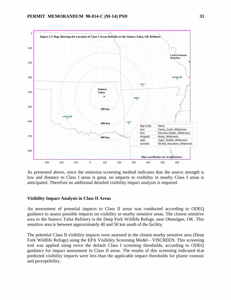
PERMIT MEMORANDUM 98-014-C (M-14) PSD
33
-300 -200 -100 0 100 200 300 400 500 600
-800
-700
-600
-500
-400
-300
-200
-100
0
cacr
herc
mingwild
upbu
wichwild
Figure 2-1 Map Showing the Location of Class I Areas Relative to the Sunoco Tulsa, OK Refinery
100 km
200 km
300 km
Sunoco Tulsa
Map Code Name
cacr Caney_Creek_Wilderness
herc Hercules-Glades_Wilderness
mingwild Mingo_Wilderness
upbu Upper_Buffalo_Wilderness
wichwild Wichita_Mountains_Wilderness
Map coordinates are in kilometers
Central DomainBoundary
As presented above, since the emission screening method indicates that the source strength is
low and distance to Class I areas is great, no impacts to visibility in nearby Class I areas is
anticipated. Therefore no additional detailed visibility impact analysis is required.
Visibility Impact Analysis in Class II Areas
An assessment of potential impacts to Class II areas was conducted according to ODEQ
guidance to assess possible impacts on visibility in nearby sensitive areas. The closest sensitive
area to the Sunoco Tulsa Refinery is the Deep Fork Wildlife Refuge, near Okmulgee, OK. This
sensitive area is between approximately 40 and 50 km south of the facility.
The potential Class II visibility impacts were assessed in the closest nearby sensitive area (Deep
Fork Wildlife Refuge) using the EPA Visibility Screening Model - VISCREEN. This screening
tool was applied using twice the default Class I screening thresholds, according to ODEQ
guidance for impact assessment in Class II areas. The results of this screening indicated that
predicted visibility impacts were less than the applicable impact thresholds for plume contrast
and perceptibility.

PERMIT MEMORANDUM 98-014-C (M-14) PSD
34
Impacts on Soils and Vegetation
Impacts on soils and vegetation apply only to those areas in which there is vegetation of
significant commercial or recreational value. There are not vegetation or soil types in the
Sunoco refinery area, which would be harmed by concentrations of criteria pollutants below
the national ambient air quality standards.
Impacts on Endangered Species
Because the emission of NO2 from proposed project will not impact the NAAQS, no impacts
are anticipated to occur to any listed endangered or threatened species.
Socioeconomic Analysis
The proposed construction will have no measurable affect on the community surrounding the
refinery.
SECTION VI. TRIVIAL ACTIVITIES
ODEQ has established a list of activities in OAC 252:100 Appendix J that are considered
inconsequential with regards to air emissions. Unless the activity is subject to an applicable
State or Federal requirement, these activities are not specifically identified in the permit.
However, the standard conditions of the permit specify that the facility is allowed to operate
these activities without special conditions.
SECTION VII. INSIGNIFICANT ACTIVITIES
The insignificant activity listed in OAC 252:100-8, Appendix I, applicable to this project is listed
below.
1. Emissions from storage tanks constructed with a capacity less than 39,894 gallons which store
VOC with a vapor pressure less than 1.5 psia at maximum storage temperature. The amine tank
meets this criteria.
SECTION VIII. OKLAHOMA AIR POLLUTION CONTROL RULES
OAC 252:100-1 (General Provisions) [Applicable]
Subchapter 1 includes definitions but there are no regulatory requirements.
OAC 252:100-2 (Incorporation by Reference) [See Federal Regulations for Applicability]
This subchapter incorporates by reference applicable provisions of Title 40 of the Code of
Federal Regulations listed in OAC 252:100, Appendix Q. These requirements are addressed in
the “Federal Regulations” section.

PERMIT MEMORANDUM 98-014-C (M-14) PSD
35
OAC 252:100-3 (Air Quality Standards and Increments) [Applicable]
Subchapter 3 enumerates the primary and secondary ambient air quality standards and the significant
deterioration increments. At this time, all of Oklahoma is in “attainment” of these standards.
OAC 252:100-5 (Registration, Emissions Inventory and Annual Operating Fees) [Applicable]
Subchapter 5 requires sources of air contaminants to register with Air Quality, file emission
inventories annually, and pay annual operating fees based upon total annual emissions of
regulated pollutants. Emission inventories were submitted and fees paid for previous years as
required.
OAC 252:100-8 (Permits for Part 70 Sources) [Applicable]
This subchapter sets forth permit application fees and the substantive requirements for operating
permits required by 40 CFR Part 70 sources. Part 5 includes the general administrative
requirements for Part 70 permits. Any planned changes in the operation of the facility that result
in emissions not authorized in the permit and that exceed the “Insignificant Activities” or
“Trivial Activities” thresholds require prior notification to AQD and may require a permit
modification. Insignificant activities refer to those individual emission units either listed in
Appendix I or whose actual calendar year emissions do not exceed the following limits.
5 TPY of any one criteria pollutant
2 TPY of any one hazardous air pollutant (HAP) or 5 TPY of multiple HAPs or 20%
of any threshold less than 10 TPY for a HAP that the EPA may establish by rule
Emission limitations and operational requirements necessary to assure compliance with all
applicable requirements for all sources are taken from the construction permit application, or
developed from the applicable requirement.
OAC 252:100-9 (Excess Emissions Reporting Requirements) [Applicable]
In the event of any release that results in excess emissions, the owner or operator of such facility
shall notify the Air Quality Division as soon as the owner or operator of the facility has
knowledge of such emissions, but no later than 4:30 p.m. the next working day. Within ten (10)
working days after the immediate notice is given, the owner or operator shall submit a written
report describing the extent of the excess emissions and response actions taken by the facility. In
addition, if the owner or operator wishes to be considered for the exemption established in
252:100-9-3.3, a Demonstration of Cause must be submitted within 30 calendar days after the
occurrence has ended.
OAC 252:100-13 (Open Burning) [Applicable]
Open burning of refuse and other combustible material is prohibited except as authorized in the
specific examples and under the conditions listed in this subchapter.
OAC 252:100-19 (Particulate Matter (PM)) [Applicable]
Section 19-4 regulates emissions of PM from new and existing fuel-burning equipment, with
emission limits based on maximum design heat input rating. Appendix C specifies a PM
emission limitation of 0.60 lbs/MMBTU for all equipment at this facility with a heat input rating
of 10 Million BTU per hour (MMBTUH) or less and sets a most restrictive rating of 0.10

PERMIT MEMORANDUM 98-014-C (M-14) PSD
36
lb/MMBTU for the largest equipment. Fuel-burning equipment is defined in OAC 252:100-1 as
“combustion devices used to convert fuel or wastes to usable heat or power.” Thus, the fuel-
burning equipment listed in this project, Boilers 3, 4, 7, 8, and 9 and Heaters B4101 and B4102,
are subject to the requirements of this subchapter. Gas-fired fuel-burning equipment at the
facility burns either RFG or commercial grade natural gas (or its equal). RFG is a mixture of
various process unit light gases that contain hydrogen (non-particle emitting) and methane
through butane light hydrocarbons. RFG is a dry gas, free of liquid particles due to liquid
knockout collection drums prior to final fuel end use. Dry gas is recognized by EPA to be at
least as clean burning, as to particulates, as commercial grade natural gas. Since AP-42 has no
distinct factor for dry gas mixtures the following demonstrations are based on the natural gas
(methane) factors. Table 1.4-2 of AP-42 lists the total PM emission factor for equipment
burning natural gas to be 7.6 lbs/106ft
3. If we make the conservatively high assumption that PM
emissions are related only to volume and that heat content has no effect, then the gas with the
highest PM emission in units of pounds per MMBtu will be the gas with the lowest heating
value. The lowest heating value found is 584 Btu/DSCF, implying emissions of 0.013 lbs
PM/MMBtu. This conservative result is still a factor of 10 below the 0.10 lb/MMBtu most
restrictive allowance identified in the introductory paragraph for any equipment at the facility.
OAC 252:100-25 (Visible Emissions and Particulates) [Applicable]
No discharge of greater than 20% opacity is allowed except for short-term occurrences which
consist of not more than one six-minute period in any consecutive 60 minutes, not to exceed
three such periods in any consecutive 24 hours. In no case shall the average of any six-minute
period exceed 60% opacity. When burning natural gas or refinery fuel gas there is very little
possibility of exceeding these standards.
OAC 252:100-29 (Fugitive Dust) [Applicable]
No person shall cause or permit the discharge of any visible fugitive dust emissions beyond the
property line on which the emissions originated in such a manner as to damage or to interfere
with the use of adjacent properties, or cause air quality standards to be exceeded, or to interfere
with the maintenance of air quality standards. Under normal operating conditions, this facility has
negligible potential to violate this requirement; therefore it is not necessary to require specific
precautions to be taken.
OAC 252:100-31 (Sulfur Compounds) (Applicable]
Part 2 concerns ambient concentrations of SO2 and H2S for new and existing equipment.
Emissions of sulfur compounds from any existing facility shall not result in an ambient air
concentration outside the facility property line greater than those specified at §31-7(a) as to SO2
and §31-7(b) as to H2S. There are no significant H2S emission points.
The facility claims to be in compliance based on AERMOD ambient air quality modeling
submitted to the Air Quality Division in February 2003. AERMOD modeling, using building
and stack downwash features, was applied to area-wide ambient air receptors. Actual daily
emissions from Sunoco were modeled with concurrent meteorology to reflect actual impacts.
Additional AERMOD modeling was applied to area-wide ambient air receptors. Actual daily
emissions from Sunoco were modeled with coincident meteorology from the past five years.

PERMIT MEMORANDUM 98-014-C (M-14) PSD
37
Exceedances were shown in a small area immediately east of Sunoco. Modeled concentrations
were compared to monitored concentrations from EPA/DEQ monitoring sites 501, 175, and 235,
showing that AERMOD modeled impacts at the monitors exceeded the actual measured
concentrations. Sunoco’s consultant (ERM) refers to these as “false exceedances” of the 24-hr
130 g/m3 standard.
ERM and Sunoco concluded that because the AERMOD model over-predicts ambient
concentrations, modeling data alone cannot be relied upon to demonstrate ongoing compliance.
To prevent exceedances (shown by EPA/DEQ monitoring) and to determine compliance with the
ambient air quality standards of §31-7(a), Sunoco will conduct monitoring of the ambient air
quality and take action as described below: The knowledge of what significant variables affect
refinery SO2 emissions played a major role in determining that the actions described in the
following will be adequate to keep the facility’s SO2 emissions in compliance.
1. Monitor SO2 ambient air concentrations measured at the east perimeter of the refinery. This
will consist of a portable instrument operated for a period of 1 hour during each 12-hour period
(2 times per day). Compliance with the 24-hour concentration limit will be presumed as long as
all readings are below the detection limits of 0.1 ppmv.
2. For any hourly measurement of 0.1 ppmv or greater, Sunoco will continue hourly monitoring
until levels are below 0.1 ppmv. At any time that 6 consecutive hourly measurements exceed 0.1
ppmv, Sunoco will take actions to reduce SO2 emissions to less than the target value.
3. Monitor and record meteorological data from measurement equipment located at the refinery.
4. Sunoco will submit a report to the Division Director by the 30th
day following the end of each
calendar quarter that lists all monitoring data, meteorological data, and actions taken to reduce
SOx emissions in the event of 6 consecutive hourly readings above 0.1 ppmv.
5. Excess Emissions will be reported pursuant to the requirements of OAC 252:100-9.
Part 5 contains new equipment standards. As used here, “new” refers to any equipment
constructed or modified after July 1, 1972, with certain exceptions, as defined in §31-2.
Paragraph 31-25(a)(1) covers gas-fired fuel-burning equipment. The equipment listed below is
presumed in compliance because this equipment burns only commercial pipeline quality natural
gas or gas that is equal or better or for B4101 and B4102 NSPS Subpart J compliant gas.
1. #7 Boiler
2. #8 Boiler
3. #9 Boiler
4. Heater B4101
5. Heater B4102
Section 31-26 (Petroleum and natural gas processes)
As defined in §31-2, “petroleum and natural gas processes includes equipment used in
processing crude and/or natural gas into refined products and includes catalytic cracking units,
catalytic reforming units, and many others. This regulation requires that H2S from the petroleum

PERMIT MEMORANDUM 98-014-C (M-14) PSD
38
process equipment be removed from the exhaust stream or oxidized to SO2. An SRU shall have
the sulfur reduction efficiency required in 252.100-31-26 (a)(2)(D) which is 94.1% for a 20.1
LTPD SRU. The proposed SRU/TGTU/Incinerator in the Diesel Upgrade Project will exceed
this requirement.
OAC 252:100-33 (Nitrogen Oxides) [Applicable]
This subchapter limits new fuel-burning equipment with rated heat input greater than or equal to
50 MMBTUH to emissions of 0.20 lbs of NOX per MMBTU, three-hour average for gas-fired
equipment, 0.30 lbs/MMBTU for liquid-fired equipment, and 0.70 lbs/MMBTU for solid fuel-
fired equipment. Most of the fuel-burning equipment at this facility is either too small or was
constructed, rebuilt, or modified before the effective date of February 14, 1972 for “new”
equipment. The following table indicates the compliance status of affected units.
Equipment MMBTUH Emission factor and source
#7 Boiler 150 0.20 lb/MMBTU, stack test of identical boiler #9
#8 Boiler 150 0.20 lb/MMBTU, stack test of identical boiler #9
#9 Boiler 150 0.20 lb/MMBTU, stack test
#2 Plat PH-5 52 0.15 lb/MMBTU, manufacturer’s data.
Coker B-1 60 0.09 lb/MMBtu, manufacturer’s data, 0.06 lb/MMBTU per
7/22/92 stack test.
MEK H-101 81 0.15 lb/MMBtu, manufacturer’s data.
DHT Heater
B4102
53.7 0.03 lb/MMBtu, manufacturer’s data
OAC 252:100-35 (Carbon Monoxide) [Not Applicable]
The project does not involve the installation or modification of any of the following equipment:
gray iron cupola, blast furnace, basic oxygen furnace, petroleum catalytic cracking unit, or
petroleum catalytic reforming unit. The facility is not located in, nor impacts, a nonattainment
area.
OAC 252:100-37 (Volatile Organic Materials) [Applicable]
Part 3 requires storage tanks constructed after December 28, 1974 with a capacity of 40,000
gallons or more and storing a VOC with a vapor pressure greater than 1.5 psia to either be operated
as a pressure vessel or be equipped with internal/external floating roofs or vapor recovery devices.
The two new tanks for this project are exempt because they store liquids with a vapor pressure less
than 1.5 psia.
The following tanks will store products from the DHT project. All of these tanks were
constructed before the applicability date of any rules and contain liquids with vapor pressure
below any of the thresholds necessary to make the tanks subject to any state rules affecting
“existing” tanks.
EU Point ID BBL
Tk9 Tk9 7000
Tk10 Tk10 7000
15946 Tk217 7000
EU Point ID BBL
6377 Tk404 72273
6378 Tk405 72443
13578 Tk406 71526
6379 Tk407 71526

PERMIT MEMORANDUM 98-014-C (M-14) PSD
39
EU Point ID BBL
13568 Tk218 7000
6371 Tk323 7000
Part 3 regulates loading facilities. The following loading racks handle products from the DHT
project but are not subject to OAC 252:100-37-16 because the units load VOCs with vapor
pressures less than 1.5 pounds per square inch, per §37-4(a).
EU Equipment Point ID Installed Date
NA Diesel Rail Loading Rack 1986
NA Diesel Truck Loading Rack
(At Truck Loading Dock)
Section 37-36 requires fuel-burning equipment to be operated and maintained so as to minimize
VOC emissions. Temperature and available air must be sufficient to provide essentially
complete combustion. Refinery fuel gas combustion devices are designed to provide essentially
complete combustion of organic materials.
Section 37-37 regulates water separators that receive water containing more than 200 gallons per
day of VOC. Any new or existing waste water systems at the refinery are subject to NSPS
Subpart QQQ, which contains standards more stringent than Part 7.
Section 37-38 sets standards for all rotating pumps or compressors handling VOC, but §37-38(b)
exempts all pumps and compressors subject to NSPS Subparts VV, GGG, or KKK from this
requirement. The facility’s pumps and compressors are subject to 40 CFR 60 Subparts VV or
GGG and are thus exempt.
OAC 252:100-39 (VOC in Non-Attainment and Former Nonattainment Areas) [Applicable]
Section 39-15 (Petroleum Refinery Equipment Leaks) EPA test Method 21 is specified for
detecting equipment leaks. VOCs with vapor pressures less than 0.0435 psia are exempt.
Components covered by this section include, but are not limited to, pumping seals, compressor
seals, seal oil degassing vents, pipeline valves, flanges and other connections, pressure relief
devices, process drains, and open-ended pipes. All such components are tested in a monitoring
program per 15(f); actions and repairs are conducted per 15(c); records are kept per 15(g);
quarterly reports are made per 15(h); and monitoring logs are retained on-site for least two years.
Section 39-16 (Petroleum refinery process unit turnaround) Vented organic material must either
be controlled per 39-16(b)(1) & (2) or exempted per 39-16(b)(4). Requirements for contents of
the 15-day notification are listed in 39-16(b)(3). Sunoco has provided the appropriate notices for
past turnarounds and is in compliance based on standard unit turnaround practices that meet
requirements.
Section 39-18 (Petroleum refinery effluent water separators) The API separator will not process
more than 200 gallons per day of these streams or will be sealed.
Section 39-30 (Petroleum liquid storage in vessels with external floating roofs) Storage vessels
Tk307 and Tk779 are exempt per 39-30(b)(4) because they are subject to 40 CFR Part 63
Subpart CC.
Section 39-41 (Storage, loading and transport/delivery of VOCs)
Tanks Tk432 and Tk435 were previously associated with EUG 26 which was regulated through 39-
41. Tank are exempt from 39-41 because new contents have a vapor pressure less than 1.5 psia.

PERMIT MEMORANDUM 98-014-C (M-14) PSD
40
OAC 252:100-42 (Toxic Air Contaminants (TAC)) [Applicable]
This subchapter regulates toxic air contaminants (TAC) that are emitted into the ambient air in
areas of concern (AOC). Any work practice, material substitution, or control equipment required
by the Department prior to June 11, 2004, to control a TAC, shall be retained, unless a
modification is approved by the Director. Since no AOC has been designated there are no
specific requirements for this facility at this time.
OAC 252:100-43 (Testing, Monitoring, and Recordkeeping) [Applicable]
This subchapter provides general requirements for testing, monitoring and recordkeeping and
applies to any testing, monitoring or recordkeeping activity conducted at any stationary source.
To determine compliance with emissions limitations or standards, the Air Quality Director may
require the owner or operator of any source in the state of Oklahoma to install, maintain and
operate monitoring equipment or to conduct tests, including stack tests, of the air contaminant
source. All required testing must be conducted by methods approved by the Air Quality Director
and under the direction of qualified personnel. A notice-of-intent to test and a testing protocol
shall be submitted to Air Quality at least 30 days prior to any EPA Reference Method stack tests.
Emissions and other data required to demonstrate compliance with any federal or state emission
limit or standard, or any requirement set forth in a valid permit shall be recorded, maintained,
and submitted as required by this subchapter, an applicable rule, or permit requirement. Data
from any required testing or monitoring not conducted in accordance with the provisions of this
subchapter shall be considered invalid. Nothing shall preclude the use, including the exclusive
use, of any credible evidence or information relevant to whether a source would have been in
compliance with applicable requirements if the appropriate performance or compliance test or
procedure had been performed.
The following Oklahoma Air Pollution Control Rules are not applicable to this facility:
OAC 252:100-11 Alternative Emissions Reduction not requested
OAC 252:100-15 Mobile Sources not in source category
OAC 252:100-17 Incinerators not type of emission unit
OAC 252:100-23 Cotton Gins not in source category
OAC 252:100-24 Grain Elevators not in source category
OAC 252:100-39-43 Graphic Arts not in source category
OAC 252:100-39-44 Tire Mfg. not in source category
OAC 252:100-39-45 Dry Cleaning not in source category
OAC 252:100-39-46 Parts Coating not in source category
OAC 252:100-39-47 Aerospace Coating not in source category
OAC 252:100-39-49 Fiberglass Mfg. not in source category
OAC 252:100-47 MSW Landfills not in source category

PERMIT MEMORANDUM 98-014-C (M-14) PSD
41
SECTION IX. FEDERAL REGULATIONS
PSD, 40 CFR Part 52 [Applicable]
Sunoco is a major PSD source since it is on the list of 26 source categories and has emissions of
at least one criteria pollutant that exceeds 100 TPY. The PSD requirements for this modification
are addressed in the “PSD Review” section. Any future increases of emissions must be
evaluated for PSD if they exceed a significance level.
NSPS, 40 CFR Part 60 [Subparts A, J, GGGa, and QQQ Applicable to this Project]
The following paragraphs are general in nature, with some reference to specific facilities. The
Specific Conditions contain specific requirements under NSPS for all affected facilities.
Subpart A, General Provisions. This subpart requires the submittal of several notifications for
NSPS-affected sources, which, for this project, are two new process heaters, a Sulfur Recovery
Unit, and new fugitive equipment. Within 30 days after starting construction of the affected
sources, the permittee must notify DEQ that construction has commenced. A notification of the
actual date of initial startup of any affected source must be submitted within 15 days after such
date. Initial performance tests are to be conducted within 60 days of achieving the maximum
production rate, but not later than 180 days after initial startup of the source. The permittee must
notify DEQ at least 30 days prior to any initial performance test and must submit the results of
the initial performance tests to DEQ. The permit will require compliance with the notification
requirements set forth in Subpart A.
Subpart Db (Industrial-Commercial-Institutional Steam Generating Units for Which
Construction Is Commenced After June 19, 1984)
There are no units constructed or modified after the effective date of the standard. The following
units were constructed or modified prior to the effective date of the standard.
EU Point ID Construction Date
106A #3 Boiler 1954
106B #4 Boiler 1957
Subpart J, Petroleum Refineries. This subpart applies to the following affected facilities in
petroleum refineries: Claus sulfur recovery plant, fuel gas combustion devices, and, FCCU
catalyst regenerators.
Claus Sulfur Recovery Plant
For Claus sulfur recovery plants with an oxidation control system or a reduction control system
followed by incineration, Subpart J limits SO2 emissions to 250 ppmvd at 0% excess air. The
new SRU is subject to this emission limit, continuous emission monitoring, and the
recordkeeping and reporting requirements of this subpart. All applicable requirements have been
incorporated into the permit.
Fuel Gas Combustion Devices
Fuel gas combustion device means any equipment, such as process heaters, boilers and flares
used to combust fuel gas, except facilities in which gases are combusted to produce sulfur or

PERMIT MEMORANDUM 98-014-C (M-14) PSD
42
sulfuric acid. Fuel gas means any gas which is generated at a petroleum refinery and which is
combusted. Fuel gas also includes natural gas when the natural gas is combined and combusted
in any proportion with a gas generated at a refinery. Fuel gas does not include gases generated
by catalytic cracking unit catalyst regenerators and fluid coking burners. All fuel gas
combustion devices which commence construction or modification after June 11, 1973, are
subject to a fuel gas H2S limitation of 0.10 grains of H2S/DSCF which is required to be
continuously monitored and recorded. The two new process heaters (B4101 & B4102) are
considered refinery fuel gas combustion devices. The two new process heaters (B4101 & B4102)
are subject to Subpart J.
#2 Platformer PH-5 & PH-6 Heaters operate under an Alternative Monitoring Plan for NSPS
Subpart J Fuel Gas approved May 31, 2001. However, the PH-6 heater is not subject to NSPS J
because it has not been constructed/modified/reconstructed since the effective date. A request was
approved in 2004 to allow boilers 7, 8, and 9 to burn absorber tower offgas, so the boilers are now
subject to NSPS J and follow the same alternative monitoring plan as heaters PH-5 and PH-6.
The following units are not subject to NSPS Subpart J because they were constructed prior to the
applicability date of June 11, 1973.
EU Point ID Construction Date
106A #3 Boiler 1954
106B #4 Boiler 1957
The LEU flare, EU-269 (EUG-11) is not subject to NSPS Subpart J because it does not burn
refinery fuel gas except during instances of emergency fuel gas release from PRVs in the Lube
Extraction Unit.
Subpart Ja (Petroleum Refineries). On May 14, 2007, U.S. EPA proposed New Source
Performance Standards (NSPS) for new, modified, or reconstructed process units at petroleum
refineries codified in 40 CFR 60, Subpart Ja. Only those affected facilities that begin
construction, modification, or reconstruction after the date the proposed rule was published in the
Federal Register would be affected by the proposed Subpart Ja standards. This project would be
subject to Subpart Ja as it is proposed.
Subpart Kb (VOL Storage Vessels) applies to volatile organic liquids storage vessels for which
construction, reconstruction, or modification commenced after July 23, 1984, and which have a
capacity of 75 cubic meters (m3) or more. Tanks with capacity greater than or equal to 151 m
3 and
storing VOL with TVP less than 3.5 kPa ( 0.5 psia) are exempt from Kb, as are tanks with capacity
greater than or equal to 75 m3 and less than 151 m
3 that store VOL with TVP less than 15.0 kPa (
2.2 psia). Tanks with capacity greater than or equal to 151 m3 and storing VOL with TVP equal to
or greater than 5.2 kPa ( 0.75 psia) but less than 76.6 kPa ( 11.1 psia) are required to have the
controls described in §60.112b(a). Tanks with capacity greater than or equal to 75 m3 and less than
151 m3 and storing VOL with TVP equal to or greater than 27.6 kPa ( 4.0 psia) but less than 76.6
kPa are also required to have the controls described in §60.112b(a). Tanks with TVP greater than
76.6 kPa must install the closed systems described in §60.112b(b). Tanks subject to the controls of
§60.112b are subject to the testing and inspection requirements of §60.113b and the reporting and

PERMIT MEMORANDUM 98-014-C (M-14) PSD
43
recordkeeping requirements of §60.115b. All tanks, regardless of controls, are subject to the
monitoring requirements of §60.116b. Compliance is per monitoring specified at 60.113(b), and
records and reporting as specified at sections 60.115(b) and 60.116(b). Tanks in EUGs 21, 22, and
23 are affected facilities under Subpart Kb. Tank inspections are documented electronically on
the Refinery Tanks Database. Electronic documentation records the date of the inspection, any
defects noted, and the initials of the inspector.
The amine tank is exempt based on the vapor pressure of the VOL stored and the sour water tank
is exempt because it does not store a VOL.
Subpart VV, Equipment Leaks of VOC in the Synthetic Organic Chemical Manufacturing
Industry (SOMCI). Although the refinery is not an affected facility, NSPS, Subpart GGG and the
refinery MACT (40 CFR 63 Subpart CC) makes extensive reference to this NSPS subpart.
Subpart VVa, Equipment Leaks of VOC in the Synthetic Organic Chemical Manufacturing
Industry (SOMCI) for Which Construction, Reconstruction, or Modification Commenced After
November 7, 2006. Although the refinery is not an affected facility, NSPS, Subpart GGGa makes
extensive reference to this NSPS subpart. All equipment in VOC service affected under this
permit is subject to NSPS, Subpart GGGa or NESHAP Subpart CC.
Subpart GGG (Standards of Performance for Equipment Leaks of VOC in Petroleum Refineries
for which Construction, Reconstruction, or Modification Commenced After January 4, 1983, and
on or Before November 7, 2006) affects each valve, pump, pressure relief device, sampling
connection system, open-ended valve or line, and flange or other connector in VOC service which
commenced construction or modification after January 4, 1983, and on or Before November 7,
2006 and which is located within a process unit in a petroleum refinery. Subpart GGG requires the
leak detection, repair, and documentation procedures of NSPS Subpart VV. Compressors in
hydrogen service (defined as serving streams more than 50% by volume hydrogen) are exempt from
all requirements other than demonstrating that a stream can never be reasonably expected to contain
less than 50% by volume hydrogen. Those pressure-relief devices vented to a control device (flare)
are exempted from periodic monitoring requirements. Equipment subject to this subpart and
compliance records are maintained on-site in an electronic database. All equipment in VOC
service affected under this permit is subject to NSPS, Subpart GGG, NESHAP Subpart CC or
OAC 252:100-39-15.
All Leak Detection and Repair (LDAR) reporting required by 40 CFR 60, Subpart GGG (semi-
annual), and 40 CFR 63, Subpart CC (semi-annual) has been consolidated to simplify
overlapping requirements, based on discretion granted to the state authorities by EPA. All
LDAR reporting is included in the MACT Semi-annual report covering all monitoring required
from January 1st through June 30th
and July 1st through December 31st. Reports are due 60 days
after the end of each six month period per 40 CFR 63.654(g).
Subpart GGGa (Standards of Performance for Equipment Leaks of VOC in Petroleum Refineries
for which Construction, Reconstruction, or Modification Commenced After November 7, 2006).
On November 16, 2007, EPA published Subpart GGGa for affected facilities located in
petroleum refineries that begin construction, modification, or reconstruction after November 7,
2006. The subpart establishes emission standards for monitoring, detection and repair of

PERMIT MEMORANDUM 98-014-C (M-14) PSD
44
equipment leaks in petroleum refineries similar to NSPS Subpart GGG, however there are some
differences and new requirements in NSPS Subpart GGGa.
The primary updates include a lowered leak definitions for pumps and valves; the addition of
recordkeeping requirements for all monitored equipment; and the addition of calibration drift
assessment.
Certain new components associated with the Diesel Upgrade Project will be subject to the
equipment leak standards. These components will be included in the refinery’s leak detection
and repair program.
Subpart QQQ (VOC Emissions from Petroleum Refinery Wastewater Systems) applies to
individual drain systems, oil-water separators, and aggregate facilities located in petroleum
refineries and for which construction, reconstruction, or modification commenced after May 4,
1987. All existing wastewater systems were constructed or modified prior to the effective date of
the standard. A new oil-water separator with drain systems will be constructed as part of this
project and they will be subject to Subpart QQQ. This project will involve physical changes to
individual drain systems in the form of new process drains and junction boxes. New drains
installed as part of this project must be equipped with water seal controls and the applicant must
comply with the monitoring, testing, recordkeeping, and reporting requirements of Subpart QQQ.
All applicable requirements have been incorporated into the permit.
NESHAP, 40 CFR Part 61 [Subparts M and FF Applicable]
Subpart M (Asbestos) Molded or wet-applied friable asbestos insulation installation or
reinstallation is prohibited per 61.148. The most likely activity that might be affected is the
renovation or demolition of structures or equipment containing asbestos. Rules concerning such
activities are found in §§60.145 and 60.150.
Subpart FF (Benzene Waste Operations) Affected sources are benzene-containing waste streams,
as identified in EUG 12 for the wastewater processing system. Numerous standards apply to
tanks, impoundments, and other activities if the total annual benzene (TAB) quantity exceeds 10
megagrams. Test methods and procedures used in calculating the TAB are found in §61.355,
paragraphs (a) through (c). Because the refinery has TAB less than 10 Mg, it is subject to only
the recordkeeping, reporting, and testing requirements found in §§61.355, 356, and 357.
NESHAP, 40 CFR Part 63 [Subparts CC and UUU are Applicable to this Project]
The following paragraphs are general in nature, with some reference to specific facilities. The
Specific Conditions contain specific requirements under NESHAP for all Sunoco affected facilities.
Subpart R (Gasoline Distribution Facilities {Bulk Gasoline Terminals and Pipeline Breakout
Stations})
The refinery has a gasoline terminal that is subject to NESHAP MACT Subpart CC which
requires compliance with some provisions of this subpart.
PERMIT MEMORANDUM 98-014-C (M-14) PSD
45
Subpart Q (Industrial Process Cooling Towers)
The provisions of this subpart apply to all new and existing industrial process cooling towers that
are operated with chromium-based water treatment chemicals on or after September 8, 1994, and
are either major sources or are integral parts of facilities that are major sources. The refinery
ceased the use of chromium-based treatment before this MACT was issued.
Subpart CC (Petroleum Refineries)
Affected facilities include process vents, storage vessels, wastewater streams and treatment,
equipment leaks, gasoline loading racks, marine vessel loading systems, and pipeline breakout
stations. Of the facilities named in CC, storage tanks, equipment leaks, process vents,
wastewater streams and treatment, and a gasoline loading rack are affected facilities at Sunoco.
Storage tanks Existing storage tanks with HAP concentrations above 4%W and which have vapor pressures
above 1.5 psia are required to implement controls identical to NSPS Subpart Kb. Tk 307 and
Tk779 (EUG19) are Group 1 Storage Vessels as defined in 63.641 and are to be controlled and
monitored per 63.646. Reports and records required for these tanks are found at 63.654. General
Provisions for startup/shutdown/malfunction (SSM) plans, as defined at 63.641, are found at 40
CFR 63.6(e)(3). Semi-annual and immediate reporting requirements are listed at 63.10(d)(5).
Electronic documentation, including the date of the inspection, any defects noted, and the initials
of the inspector, is maintained on-site in the facility’s “Refinery Tanks Database.”
EUG 20 lists Group 2 Storage Vessels as defined at 63.641. Subparagraph 63.654(i)(1)(iv)
requires a determination of Group 2 Tanks. The facility maintains a list of tanks that do not
contain any HAPs and are not Group 2 Tanks per 63.640(a)(2).
Process Vents Any refinery unit process vent with greater than 20 ppmv HAPs and which emits more than 33
kg/day of VOC is subject to control requirements. Subpart CC requires affected vents to be
equipped with 98% efficient controls, be vented to a flare, be vented to a combustion unit
firebox, or be reduced to 20 ppmv HAP or less. Group 1 Process vents include the Coker Flare
(EUG 14). Group 1 Process Vents are vents for which the total organic HAP concentration is
greater than or equal to 20 ppmv, and whose total VOC emissions are greater than or equal to 33
kg per day (75 lbs/day).
Equipment Leaks Portions of the project contain Hazardous Air Pollutant (HAP) fugitive equipment component
sources that exist in the refinery. Two compliance options are given at 63.648, consisting of a
modified 40 CFR 63, Subpart H method, and a modified 40 CFR 60, Subpart VV method. The
Sunoco Refinery currently chooses to follow the Subpart VV option. The 40 CFR 63 Subpart
CC modifications to Subpart VV are primarily in applicability and component exemptions.
Applicability is limited to components that contain equal to or more than 5% by weight HAP.
Exemptions in addition to Subpart VV include wastewater system drains, storage tank sample
valves, and tank mixers. Also, reciprocating pumps in light liquid service and reciprocating
compressors are exempt from 60.482 if recasting the distance pieces or new equipment is
required. Subpart VV requires, among other things, leak detection and repair at valves in

PERMIT MEMORANDUM 98-014-C (M-14) PSD
46
gas/vapor and light liquid service, and offers three options for such valves. The first is the main
standard at 40 CFR 60.482-7, which requires monthly monitoring unless the valve shows no
leaks after two successive months after which the valve may be monitored quarterly until it
indicates leakage. The second option is given at 60.483-1, in which valves are tested initially,
and then annually or as requested by DEQ, and the percentage of leaking valves is not allowed to
exceed 2%. The third option is given at 60.483-2, in which good leak performance leads to skip
periods of monitoring that leads to annual monitoring so long as the quantity of leaking
components vs. total number of components remains below 2%. The use of either of the second
two options requires prior notification to DEQ. This facility currently follows the base
procedures given at 60.482-7, but requests alternative scenario status for the other two options
since they represent another form of compliance measurement, and because they require
notification to DEQ. Whether these scenarios will be used or not depends on the facility’s
analysis of the benefits of invoking them. At the present time these options are moot because
OAC 252:100-39-15 requires quarterly monitoring of valves. If Section 39-15 is modified in the
future to provide reduced monitoring after periods of continuous compliance, the facility will
select the compliance option described in §63.648(a)(2). The facility will also comply with the
leak monitoring requirements in the Federal Consent Decree.
All Leak Detection and Repair (LDAR) reporting required by 40 CFR 60 Subpart GGGa (semi-
annual), and 40 CFR 63 Subpart CC (semi-annual) has been consolidated to simplify overlapping
requirements. All LDAR reporting is included in the MACT semi-annual report covering all
monitoring required from January 1st through June 30th
and July 1st through December 31st.
Reports are due 60 days after the end of each six month period per 40 CFR 63.654(g).
Wastewater Streams and Treatment
Requirements for the wastewater system are defined at 63.647 as equivalent to the provisions of
40 CFR 61, Subpart FF. Recordkeeping, reporting, and monitoring is also defined at 63.654 to
be what is required at 61.356 and 61.357. Compliance with 40 CFR 61, Subpart FF indicates
compliance with 40 CFR 63, Subpart CC.
Subpart UUU (Petroleum Refineries: Catalytic Cracking Units, Catalytic Reforming Units, and
Sulfur Recovery Units). The new SRU is subject to this subpart. The subpart affects the
following parts of this project:
1. The process vent or group of process vents on Claus or other types of sulfur recovery
plant units or the tail gas treatment units serving sulfur recovery plants, that are
associated with sulfur recovery; and
2. Each bypass line serving a new, existing, or reconstructed catalytic cracking unit,
catalytic reforming unit, or sulfur recovery unit. This means each vent system that
contains a bypass line (e.g., ductwork) that could divert an affected vent stream away
from a control device used to comply with the requirements of this subpart.
Sulfur Recovery Units
Sulfur recovery units subject to the NSPS, Subpart J, SO2 emission limit (≤ 250 ppmvd @
0% excess air) must comply with the NSPS Subpart J, SO2 emission limit. The new SRU
is subject to NSPS, Subpart J and will meet all applicable requirements of this subpart and

PERMIT MEMORANDUM 98-014-C (M-14) PSD
47
NSPS, Subpart J. The SRU will use a CEM to show compliance with this standard on a
12-hour rolling average basis.
Bypass Lines
The SRU has bypass lines that are vented to the flare system. Bypass lines must meet the
work practice standards in Table 36 and continuous compliance requirements of Table 39
of this subpart.
An operation, maintenance, and monitoring plans is required to be prepared and submitted for
the SRU and Bypass Lines. The facility will submit the plan with their initial compliance
demonstration and their startup, shutdown, and malfunction plan. All applicable requirements of
this subpart have been incorporated into the permit.
Subpart DDDDD (National Emission Standards for Hazardous Air Pollutants for Industrial,
Commercial and Institutional Boilers and Process Heaters) In March, 2007, the EPA filed a
motion to vacate and remand this rule back to the agency. The rule was vacated by court order,
subject to appeal, on June 8, 2007. No appeals were made and the rule was vacated on July 30,
2007. Existing and new small gaseous fuel boilers and process heaters (less than 10 MMBtu/hr
heat rating) were not subject to any standards, recordkeeping, or notifications under Subpart
DDDDD.
EPA is planning on issuing guidance (or a rule) on what actions applicants and permitting
authorities should take regarding MACT determinations under either Section112(g) or Section
112(j) for sources that were affected sources under Subpart DDDDD and other vacated MACTs.
It is expected that the guidance (or rule) will establish a new timeline for submission of section
112(j) applications for vacated MACT standards. At this time, AQD has determined that a
112(j) determination is not needed for sources potentially subject to a vacated MACT, including
Subpart DDDDD. This permit may be reopened to address Section 112(j) when necessary.
Based on the original rule applicability, Boilers 3, 4, 7, 8, and 9 and DHT Heaters B4101 and
B4102 are subject for gaseous fired units.
Compliance Assurance Monitoring, 40 CFR Part 64 [Not Applicable at this Time]
This part applies to any pollutant-specific emission unit at a major source that is required to
obtain an operating permit, for any application for an initial operating permit submitted after
April 18, 1998, that addresses “large emissions units,” or any application that addresses “large
emissions units” as a significant modification to an operating permit, or for any application for
renewal of an operating permit, if it meets all of the following criteria.
It is subject to an emission limit or standard for an applicable regulated air pollutant
It uses a control device to achieve compliance with the applicable emission limit or standard
It has potential emissions, prior to the control device, of the applicable regulated air
pollutant of 100 TPY or 10/25 TPY of a HAP
No equipment from the DHT project is subject to CAM.

PERMIT MEMORANDUM 98-014-C (M-14) PSD
48
Chemical Accident Prevention Provisions, 40 CFR Part 68 [Applicable]
Toxic and flammable substances subject to this regulation are present in the facility in quantities
greater than the threshold quantities. A Risk Management Plan was submitted to EPA on June 1,
1999, and resubmitted as required by rule.
Stratospheric Ozone Protection, 40 CFR Part 82 [Applicable]
These standards require phase out of Class I & II substances, reductions of emissions of Class I
& II substances to the lowest achievable level in all use sectors, and banning use of nonessential
products containing ozone-depleting substances (Subparts A & C); control servicing of motor
vehicle air conditioners (Subpart B); require Federal agencies to adopt procurement regulations
which meet phase out requirements and which maximize the substitution of safe alternatives to
Class I and Class II substances (Subpart D); require warning labels on products made with or
containing Class I or II substances (Subpart E); maximize the use of recycling and recovery upon
disposal (Subpart F); require producers to identify substitutes for ozone-depleting compounds
under the Significant New Alternatives Program (Subpart G); and reduce the emissions of halons
(Subpart H).
Subpart A identifies ozone-depleting substances and divides them into two classes. Class I
controlled substances are divided into seven groups; the chemicals typically used by the
manufacturing industry include carbon tetrachloride (Class I, Group IV) and methyl chloroform
(Class I, Group V). A complete phase-out of production of Class I substances is required by
January 1, 2000 (January 1, 2002, for methyl chloroform). Class II chemicals, which are
hydrochlorofluorocarbons (HCFCs), are generally seen as interim substitutes for Class I CFCs.
Class II substances consist of 33 HCFCs. A complete phase-out of Class II substances,
scheduled in phases starting by 2002, is required by January 1, 2030.
This facility does not utilize any Class I & II substances in its manufacturing processes.
SECTION X. COMPLIANCE
Tier Classification and Public Review
This application has been determined to be Tier II based on the request for a construction permit
for a Part 70 source for a facility change that is considered a significant modification as defined
in OAC 252:100-8-7.2(b)(2)(A).
The applicant has submitted an affidavit that they are not seeking a permit for land use or for any
operation upon land owned by others without their knowledge. The affidavit certifies that the
applicant owns the real property.
The applicant published the “DEQ Notice of Filing a Tier II Application” in the Tulsa World, a
daily newspaper of general circulation in Tulsa County on January 13, 2008. The notice said that
the application was available for public review at the AQD office in Tulsa or OKC. A “Notice
of Tier II Draft Permit” was published in the Tulsa World, a daily newspaper of general
circulation in Tulsa County on March 16, 2008. A copy of the draft was available at the DEQ
Regional Office at Tulsa and the AQD office in Oklahoma City, as well as on the DEQ website.
The facility is not located within 50 miles of any other state border. The applicant requested
concurrent Public and EPA review. The permit was forwarded to EPA for a 45 day review

PERMIT MEMORANDUM 98-014-C (M-14) PSD
49
period. There were no comments from the public. Sunoco had minor comments to fix
typographical errors. The errors were fixed and did not require additional public or EPA review.
There were no comments from EPA during the 45 day review period.
Information on all permit actions is available for review by the public in the Air Quality section
of the DEQ Web page: http://www.deq.state.ok.us/
Fee Paid
Modification of a Part 70 source construction permit fee of $1,500.
SECTION XI. SUMMARY
This facility was constructed as described in the application. There are no active Air Quality
compliance or enforcement issues that would affect the issuance of this permit. Issuance of the
construction permit is recommended.

PERMIT TO CONSTRUCT
AIR POLLUTION CONTROL FACILITY
SPECIFIC CONDITIONS
SUNOCO, Inc. (R&M) Permit Number 98-014-C (M-14) PSD
Tulsa Refinery
The permittee is authorized to construct in conformity with the revised specifications submitted
to Air Quality on December 4, 2007, many supplemental data packages submitted, and with
various reviews of the interim work product provided by the applicant. The Evaluation
Memorandum dated May 23, 2008, explains the derivation of applicable permit requirements and
estimates of emissions; however, it does not contain operating limitations or permit
requirements. Commencing construction, or operations, under this permit constitutes acceptance
of, and consent to, the conditions contained herein. Only those portions of the Specific
Conditions directly affected are addressed. All other portions of the Specific Conditions are
unaffected by this modification and continue as stated in the underlying Part 70 permit.
1. Points of emission, emission limitations, and standards [OAC 252:100-8-6(a)]
A. Process Heaters
Process Heaters
Emissions NOx VOC PM10 CO SO2
MMBtu/hr lb/ MMBtu* TPY lb/hr TPY lb/hr TPY lb/hr TPY lb/
MMBtu** TPY
DHT Heater (B4101) 44.0 0.03 5.78 0.43 1.25 0.59 1.72 6.52 19.05 0.03 2.42 DHT Heater (B4102) 53.7 0.03 7.06 0.53 1.52 0.72 2.10 7.96 23.24 0.03 2.95
*Short term NOx limitation per BACT based on average of three 1-hour performance test runs **Short term SOx limitation based on conversion of NSPS Subpart J limitation of 160 ppmv H2S to SO2. Limit based
on 3-hr averaging period. 160ppmvH2S * 64lb SO2/lbmol / 379.4 scf/lb-mol / 820 btu/scf (HHV RFG) = 0.03 lb
SO2/mmbtu
i. B4101 and B4102 are subject to 40 CFR Part 60, Subpart J and shall comply with all
applicable requirements and standards, including but not limited to: [40 CFR Part 60]
a. §60.104 Standards for sulfur oxides. B4101 and B4102 shall combust only
pipeline grade natural gas, #2 Platformer offgas, or refinery fuel gas with a 3-hour
rolling average maximum H2S concentration of 0.1 gr/dscf (160 ppmv @ 60oF).
b. §60.105 Monitoring of emissions and operations. A continuous monitoring
system shall be operated and maintained to record H2S content of the fuel gas.
c. §60.106 Test methods and procedures
d. §60.107 Reporting and recordkeeping requirements
e. §60.108 Performance test and compliance provisions
ii. Compliance of B4101 and B4102 with the SO2 emission limits of Specific Condition
1.A shall be based on a 365-day rolling average fuel gas usage and H2S content and

SPECIFIC CONDITIONS 98-014-C (M-14) PSD 2
shall be demonstrated monthly using on-line instrumentation and calculations, when
available, or the following formula:
SO2, TPY = MMSCFD * ppmvd H2S * 64 lb SO2/lb-mole * 365 days/year
2000 lb/ton * 379.4 Scf/lb-mole
iii. B4101 and B4102 shall be constructed with burners with NOX emissions limited to
no greater than 0.03 lb/MMBtu (HHV), average of three 1-hr performance test runs.
[OAC 252:100-8-6(a)]
iv. Compliance of B4101 and B4102 with the NOX, CO, and VOC annual emission
limits shall be based on a 365-day rolling average fuel gas usage and heater specific
(stack test) emission factors, when available, or the most current version emission
factors from AP-42 Table 1.4-1 plus a 20% safety factor. Compliance shall be
demonstrated monthly using on-line instrumentation and calculations, when available,
or the following formula:
TPY = MMSCFD * Btu/Scf (HHV) * EF * 365 days/year
2000 lb/ton
where EF = Emission Factor, lb/MMBtu
v. B4101 and B4102 shall be operated using good combustion practices to comply with
the emission limitations of PM10. [OAC 252:100-8-6(a)]
vi. Within 60 days of achieving maximum firing rate from the heaters, not to exceed 180
days from initial start-up, and at other such times as directed by Air Quality, the
permittee shall, for each heater, conduct performance testing for NOX, CO, and VOC
and furnish a written report to Air Quality documenting compliance with emission
limitations. Performance testing by the permittee shall use the following test methods
specified in 40 CFR Part 60:
a. Method 1: Sample and Velocity Traverses for Stationary Sources.
b. Method 2: Determination of Stack Gas Velocity and Volumetric Flow Rate.
c. Method 3 or 3A: Gas Analysis for Carbon Dioxide, Excess Air, and Dry
Molecular Weight
d. Method 4: Determination of Moisture in Stack Gases.
e. Method 7E: Determination of Nitrogen Oxide Emissions From Stationary
Sources.
f. Method 10: Determination of Carbon Monoxide Emissions From Stationary
Sources.
g. Method 18 or 25A: Determination of Volatile Organic Compounds Emissions
From Stationary Sources
h. Method 19: F-factor Methodology

SPECIFIC CONDITIONS 98-014-C (M-14) PSD 3
B. Sulfur Recovery Unit (SRU) / Tail Gas Treatment Unit (TGTU)
SRU Emissions
NOx VOC PM10 CO SO2 lb/
MMBtu* TPY lb/hr TPY lb/hr TPY lb/hr TPY ppmv** TPY
SRU Unit 0.14 4.4 2.41 7.03 1.62 4.73 1.00 2.93 250 15.93 *Short term NOx limitation per BACT based on average of three 1-hour performance test runs **Short term SOx limitation per NSPS Subpart J based on 12-hr averaging period
i. The SRU/TGTU is subject to 40 CFR Part 60, Subpart J and shall comply with all
applicable requirements and standards, including but not limited to: [40 CFR Part 60]
a. §60.104(a)(1) Standards for sulfur oxides. The SRU shall combust only pipeline
grade natural gas, #2 Platformer offgas, or refinery fuel gas with a 3-hour rolling
average maximum H2S concentration of 0.1 gr/dscf (160 ppmv @ 60oF).
b. §60.104(a)(2) Standards for sulfur oxides. The SRU (Claus sulfur recovery plant
followed by an incinerator) is limited to a 12-hour rolling average maximum SO2
concentration of 250 ppmv (dry basis) at zero percent excess air. The monitor
shall include an oxygen monitor for correcting the data for excess air.
c. §60.105 Monitoring of emissions and operations. A continuous monitoring
system shall be operated and maintained to record SO2 as required emissions into
the atmosphere (Claus unit) and record H2S in fuel (fuel gas system).
d. §60.106 Test methods and procedures
e. §60.107 Reporting and recordkeeping requirements
f. §60.108 Performance test and compliance provisions
ii. The SRU/TGTU is subject to 40 CFR Part 63, Subpart UUU and shall comply with
all applicable requirements and standards, including but not limited to:[40 CFR Part 63]
a. § 63.1568 What are my requirements for HAP emissions from sulfur recovery
units? – (a)(1), (b)(1, 3, 4, 5, 6, & 7), & (c)(1 & 2);
b. § 63.1569 What are my requirements for HAP emissions from bypass lines? –
(a)(1 & 3), (b)(1-4), & (c)(1 & 2);
c. § 63.1570 What are my general requirements for complying with this subpart? –
(a) & (c-g);
d. 63.1571 How and when do I conduct a performance test or other initial
compliance demonstration? – (a) & (b)(1-5);
e. 63.1572 What are my monitoring installation, operation, and maintenance
requirements? – (a)(1-4) & (d)(1-2);
f. 63.1574 What notifications must I submit and when? – (a)(2) & (f)(1, 2(i), 2(ii),
2(viii), 2(ix), & 2(x));
g. 63.1575 What reports must I submit and when? – (a-h);
h. 63.1576 What records must I keep, in what form, and for how long? – (a), (b)(1,
3, 4, 5), & (d-i);
i. 63.1577 What parts of the General Provisions apply to me?

SPECIFIC CONDITIONS 98-014-C (M-14) PSD 4
iii. Compliance of the SRU with the SO2 emission limits of Specific Condition 1.B shall
be based on the continuous monitoring system.
iv. The SRU shall be constructed with burners with NOX emissions limited to no greater
than 0.14 lb/MMBtu (HHV), average of three 1-hr performance test runs.
[OAC 252:100-8-6(a)]
v. Compliance of the SRU with the NOX, CO, and VOC annual emission limits shall be
based on a 365-day rolling average fuel gas usage and heater specific (stack test)
emission factors, when available, or the most current version emission factors from
AP-42 Table 1.4-1 plus a 20% safety factor. Compliance shall be demonstrated
monthly using on-line instrumentation and calculations, when available, or the
following formula:
TPY = MMSCFD * Btu/Scf (HHV) * EF * 365 days/year
2000 lb/ton
where EF = Emission Factor, lb/MMBtu
vi. The SRU shall be operated using good combustion practices to comply with the
emission limitations of PM10. [OAC 252:100-8-6(a)]
vii. Within 60 days of achieving maximum firing rate from the SRU, not to exceed 180
days from initial start-up, and at other such times as directed by Air Quality, the
permittee shall, for each heater, conduct performance testing for NOX, CO, SO2 and
VOC and furnish a written report to Air Quality documenting compliance with
emission limitations. Performance testing by the permittee shall use the following test
methods specified in 40 CFR Part 60:
a. Method 1: Sample and Velocity Traverses for Stationary Sources.
b. Method 2: Determination of Stack Gas Velocity and Volumetric Flow Rate.
c. Method 3 or 3A: Gas Analysis for Carbon Dioxide, Excess Air, and Dry
Molecular Weight
d. Method 4: Determination of Moisture in Stack Gases.
e. Method 6C: Determination of Sulfur Dioxide Emissions From Stationary Sources.
f. Method 7E: Determination of Nitrogen Oxide Emissions From Stationary
Sources.
g. Method 10: Determination of Carbon Monoxide Emissions From Stationary
Sources.
h. Method 18 or 25A: Determination of Volatile Organic Compounds Emissions
From Stationary Sources
i. Method 19: F-factor Methodology

SPECIFIC CONDITIONS 98-014-C (M-14) PSD 5
C. Oil-Water Separator Subject to NSPS, Part 60, Subpart QQQ.
EU Point Type Contents
OWS TBD Sealed Container Sour Water Stripper Feed
i. The permittee shall comply with the applicable sections of NSPS, 40 CFR Part 60,
Subpart QQQ, VOC Emissions From Petroleum Wastewater Systems.
[40 CFR 60.690-699]
2. The following records shall be maintained on-site to verify Insignificant Activities. No
recordkeeping is required for those operations, which qualify as Trivial Activities.
[OAC 252:100-8-6 (a)(3)(B)]
a. For fluid storage tanks with a capacity of less than 39,894 gallons and a true vapor
pressure less than 1.5 psia: records of the capacity of the tanks and the contents.
b. For activities (except for trivial activities) that have the potential to emit less than 5
TPY (actual) of any criteria pollutant: the type of activity and the amount of
emissions or a surrogate measure of the activity (annual).
3. Certain equipment constructed as part of the DHT project within the refinery is subject to
NSPS, 40 CFR Part 60, Subpart GGGa and all affected equipment shall comply with all
applicable requirements. [40 CFR Part 60, NSPS, Subpart GGGa]
a. 60.590a Applicability and designation of affected facility.
b. 60.591a Definitions.
c. 60.592a Standards.
d. 60.593a Exceptions.
4. The Refinery is subject to NESHAP, 40 CFR Part 61, Subpart FF and shall comply with all
applicable requirements. [40 CFR Part 61, NESHAP, Subpart FF]
a. § 61.342 Standards: General.
b. § 61.343 Standards: Tanks.
c. § 61.344 Standards: Surface Impoundments.
d. § 61.345 Standards: Containers.
e. § 61.346 Standards: Individual drain systems.
f. § 61.347 Standards: Oil-water separators.
g. § 61.348 Standards: Treatment processes.
h. § 61.349 Standards: Closed-vent systems and control devices.
i. § 61.350 Standards: Delay of repair.
j. § 61.351 Alternative standards for tanks.
k. § 61.352 Alternative standards for oilwater separators.
l. § 61.353 Alternative means of emission limitation.
m. § 61.354 Monitoring of operations.
n. § 61.355 Test methods, procedures, and compliance provisions.
o. § 61.356 Recordkeeping requirements.
p. § 61.357 Reporting requirements.

SPECIFIC CONDITIONS 98-014-C (M-14) PSD 6
5. Certain equipment within the refinery is subject to NESHAP, 40 CFR Part 63, Subpart CC
and all affected equipment shall comply with all applicable requirements.
[40 CFR Part 63, NESHAP, Subpart CC]
a. § 63. 63.642 General Standards
b. § 63.643 Miscellaneous Process Vent Provisions
c. § 63.644 Monitoring for Miscellaneous Process Vents
d. § 63.645 Test Methods and Procedures for Miscellaneous Process Vents
e. § 63.646 Storage Vessel Provisions
f. § 63.647 Wastewater Provisions
g. § 63.648 Equipment Leak Standards
h. § 63.652 Emission Averaging Provisions
i. § 63.653 Monitoring, Recordkeeping, and Implementation Plan for Emissions
Averaging
j. § 63.654 Reporting and Recordkeeping Requirements
k. The permittee shall comply with the provisions of 40 CFR Part 63 Subpart A as
specified in Appendix to Subpart CC, Table 6.
6. The permittee shall maintain records as specified in Specific Condition 1 including but not
limited to those listed below. These records shall be maintained on-site for at least five years
after the date of recording and shall be provided to regulatory personnel upon request.
[OAC 252:100-43]
a. Records showing compliance with 365-day rolling averages (monthly) established in
Specific Condition 1.
b. Records showing compliance with emission limits (monthly) established in Specific
Condition 1.
c. Heater fuel usage (monthly) and heat content (quarterly) for Heaters B4101 and
B4102.
d. Records required by 40 CFR Part 60, NSPS, Subparts A, J, GGGa, and QQQ, Part
61, NESHAP, Subparts A and FF, and Part 63, NESHAP, Subparts A, CC, and
UUU.
7. The permittee shall be authorized to operate the listed equipment continuously (24 hours per
day, every day of the year). [OAC 252:100-8]
8. The permittee shall submit an application to update the Title V Permit within 180 days of
start-up to incorporate the requirements of this permit. [OAC 252:100-8]

MAJOR SOURCE AIR QUALITY PERMIT
STANDARD CONDITIONS
(January 24, 2008)
SECTION I. DUTY TO COMPLY
A. This is a permit to operate / construct this specific facility in accordance with the federal
Clean Air Act (42 U.S.C. 7401, et al.) and under the authority of the Oklahoma Clean Air Act
and the rules promulgated there under. [Oklahoma Clean Air Act, 27A O.S. § 2-5-112]
B. The issuing Authority for the permit is the Air Quality Division (AQD) of the Oklahoma
Department of Environmental Quality (DEQ). The permit does not relieve the holder of the
obligation to comply with other applicable federal, state, or local statutes, regulations, rules, or
ordinances. [Oklahoma Clean Air Act, 27A O.S. § 2-5-112]
C. The permittee shall comply with all conditions of this permit. Any permit noncompliance
shall constitute a violation of the Oklahoma Clean Air Act and shall be grounds for enforcement
action, permit termination, revocation and reissuance, or modification, or for denial of a permit
renewal application. All terms and conditions are enforceable by the DEQ, by the
Environmental Protection Agency (EPA), and by citizens under section 304 of the Federal Clean
Air Act (excluding state-only requirements). This permit is valid for operations only at the
specific location listed.
[40 C.F.R. §70.6(b), OAC 252:100-8-1.3 and OAC 252:100-8-6(a)(7)(A) and (b)(1)]
D. It shall not be a defense for a permittee in an enforcement action that it would have been
necessary to halt or reduce the permitted activity in order to maintain compliance with the
conditions of the permit. However, nothing in this paragraph shall be construed as precluding
consideration of a need to halt or reduce activity as a mitigating factor in assessing penalties for
noncompliance if the health, safety, or environmental impacts of halting or reducing operations
would be more serious than the impacts of continuing operations. [OAC 252:100-8-6(a)(7)(B)]
SECTION II. REPORTING OF DEVIATIONS FROM PERMIT TERMS
A. Any exceedance resulting from an emergency and/or posing an imminent and substantial
danger to public health, safety, or the environment shall be reported in accordance with Section
XIV (Emergencies). [OAC 252:100-8-6(a)(3)(C)(iii)(I) & (II)]
B. Deviations that result in emissions exceeding those allowed in this permit shall be reported
consistent with the requirements of OAC 252:100-9, Excess Emission Reporting Requirements.
[OAC 252:100-8-6(a)(3)(C)(iv)]
C. Every written report submitted under this section shall be certified as required by Section III
(Monitoring, Testing, Recordkeeping & Reporting), Paragraph F.
[OAC 252:100-8-6(a)(3)(C)(iv)]

MAJOR SOURCE STANDARD CONDITIONS January 24, 2008 2
SECTION III. MONITORING, TESTING, RECORDKEEPING & REPORTING
A. The permittee shall keep records as specified in this permit. These records, including
monitoring data and necessary support information, shall be retained on-site or at a nearby field
office for a period of at least five years from the date of the monitoring sample, measurement,
report, or application, and shall be made available for inspection by regulatory personnel upon
request. Support information includes all original strip-chart recordings for continuous
monitoring instrumentation, and copies of all reports required by this permit. Where appropriate,
the permit may specify that records may be maintained in computerized form.
[OAC 252:100-8-6 (a)(3)(B)(ii), OAC 252:100-8-6(c)(1), and OAC 252:100-8-6(c)(2)(B)]
B. Records of required monitoring shall include:
(1) the date, place and time of sampling or measurement;
(2) the date or dates analyses were performed;
(3) the company or entity which performed the analyses;
(4) the analytical techniques or methods used;
(5) the results of such analyses; and
(6) the operating conditions existing at the time of sampling or measurement.
[OAC 252:100-8-6(a)(3)(B)(i)]
C. No later than 30 days after each six (6) month period, after the date of the issuance of the
original Part 70 operating permit, the permittee shall submit to AQD a report of the results of any
required monitoring. All instances of deviations from permit requirements since the previous
report shall be clearly identified in the report. Submission of these periodic reports will satisfy
any reporting requirement of Paragraph E below that is duplicative of the periodic reports, if so
noted on the submitted report. [OAC 252:100-8-6(a)(3)(C)(i) and (ii)]
D. If any testing shows emissions in excess of limitations specified in this permit, the owner or
operator shall comply with the provisions of Section II (Reporting Of Deviations From Permit
Terms) of these standard conditions. [OAC 252:100-8-6(a)(3)(C)(iii)]
E. In addition to any monitoring, recordkeeping or reporting requirement specified in this
permit, monitoring and reporting may be required under the provisions of OAC 252:100-43,
Testing, Monitoring, and Recordkeeping, or as required by any provision of the Federal Clean
Air Act or Oklahoma Clean Air Act. [OAC 252:100-43]
F. Any document submitted in accordance with this permit shall be certified by a responsible
official. This certification shall be signed by a responsible official, and shall contain the
following language: “I certify, based on information and belief formed after reasonable inquiry,
the statements and information in the document are true, accurate, and complete.” However, an
exceedance report that must be submitted within ten days of the exceedance under Section II
(Reporting Of Deviations From Permit Terms) or Section XIV (Emergencies) may be submitted
without a certification, if an appropriate certification is provided within ten days thereafter,
together with any corrected or supplemental information required concerning the exceedance.
[OAC 252:100-8-5(f), OAC 252:100-8-6(a)(3)(C)(iv), OAC 252:100-8-6(c)(1) and OAC
252:100-9-3.1(c)]

MAJOR SOURCE STANDARD CONDITIONS January 24, 2008 3
G. Any owner or operator subject to the provisions of New Source Performance Standards
(“NSPS”) under 40 CFR Part 60 or National Emission Standards for Hazardous Air Pollutants
(“NESHAPs”) under 40 CFR Parts 61 and 63 shall maintain a file of all measurements and other
information required by the applicable general provisions and subpart(s). These records shall be
maintained in a permanent file suitable for inspection, shall be retained for a period of at least
five years as required by Paragraph A of this Section, and shall include records of the occurrence
and duration of any start-up, shutdown, or malfunction in the operation of an affected facility,
any malfunction of the air pollution control equipment; and any periods during which a
continuous monitoring system or monitoring device is inoperative.
[40 C.F.R. §§60.7 and 63.10, 40 CFR Parts 61, Subpart A, and OAC 252:100, Appendix Q]
I. The permittee of a facility that is operating subject to a schedule of compliance shall submit
to the DEQ a progress report at least semi-annually. The progress reports shall contain dates for
achieving the activities, milestones or compliance required in the schedule of compliance and the
dates when such activities, milestones or compliance was achieved. The progress reports shall
also contain an explanation of why any dates in the schedule of compliance were not or will not
be met, and any preventive or corrective measures adopted. [OAC 252:100-8-6(c)(4)]
J. All testing must be conducted under the direction of qualified personnel by methods
approved by the Division Director. All tests shall be made and the results calculated in
accordance with standard test procedures. The use of alternative test procedures must be
approved by EPA. When a portable analyzer is used to measure emissions it shall be setup,
calibrated, and operated in accordance with the manufacturer’s instructions and in accordance
with a protocol meeting the requirements of the “AQD Portable Analyzer Guidance” document
or an equivalent method approved by Air Quality.
[OAC 252:100-8-6(a)(3)(A)(iv), and OAC 252:100-43]
K. The reporting of total particulate matter emissions as required in Part 7 of OAC 252:100-8
(Permits for Part 70 Sources), OAC 252:100-19 (Control of Emission of Particulate Matter), and
OAC 252:100-5 (Emission Inventory), shall be conducted in accordance with applicable testing
or calculation procedures, modified to include back-half condensables, for the concentration of
particulate matter less than 10 microns in diameter (PM10). NSPS may allow reporting of only
particulate matter emissions caught in the filter (obtained using Reference Method 5).
L. The permittee shall submit to the AQD a copy of all reports submitted to the EPA as required
by 40 C.F.R. Part 60, 61, and 63, for all equipment constructed or operated under this permit
subject to such standards. [OAC 252:100-8-6(c)(1) and OAC 252:100, Appendix Q]

MAJOR SOURCE STANDARD CONDITIONS January 24, 2008 4
SECTION IV. COMPLIANCE CERTIFICATIONS
A. No later than 30 days after each anniversary date of the issuance of the original Part 70
operating permit, the permittee shall submit to the AQD, with a copy to the US EPA, Region 6, a
certification of compliance with the terms and conditions of this permit and of any other
applicable requirements which have become effective since the issuance of this permit. The
compliance certification shall also include such other facts as the permitting authority may
require to determine the compliance status of the source.
[OAC 252:100-8-6(c)(5)(A), (C)(v), and (D)]
B. The compliance certification shall describe the operating permit term or condition that is the
basis of the certification; the current compliance status; whether compliance was continuous or
intermittent; the methods used for determining compliance, currently and over the reporting
period; and a statement that the facility will continue to comply with all applicable requirements.
[OAC 252:100-8-6(c)(5)(C)(i)-(iv)]
C. The compliance certification shall contain a certification by a responsible official as to the
results of the required monitoring. This certification shall be signed by a responsible official,
and shall contain the following language: “I certify, based on information and belief formed
after reasonable inquiry, the statements and information in the document are true, accurate, and
complete.” [OAC 252:100-8-5(f) and OAC 252:100-8-6(c)(1)]
D. Any facility reporting noncompliance shall submit a schedule of compliance for emissions
units or stationary sources that are not in compliance with all applicable requirements. This
schedule shall include a schedule of remedial measures, including an enforceable sequence of
actions with milestones, leading to compliance with any applicable requirements for which the
emissions unit or stationary source is in noncompliance. This compliance schedule shall
resemble and be at least as stringent as that contained in any judicial consent decree or
administrative order to which the emissions unit or stationary source is subject. Any such
schedule of compliance shall be supplemental to, and shall not sanction noncompliance with, the
applicable requirements on which it is based, except that a compliance plan shall not be required
for any noncompliance condition which is corrected within 24 hours of discovery.
[OAC 252:100-8-5(e)(8)(B) and OAC 252:100-8-6(c)(3)]
SECTION V. REQUIREMENTS THAT BECOME APPLICABLE DURING THE
PERMIT TERM
The permittee shall comply with any additional requirements that become effective during the
permit term and that are applicable to the facility. Compliance with all new requirements shall
be certified in the next annual certification. [OAC 252:100-8-6(c)(6)]
SECTION VI. PERMIT SHIELD
A. Compliance with the terms and conditions of this permit (including terms and conditions
established for alternate operating scenarios, emissions trading, and emissions averaging, but
excluding terms and conditions for which the permit shield is expressly prohibited under OAC

MAJOR SOURCE STANDARD CONDITIONS January 24, 2008 5
252:100-8) shall be deemed compliance with the applicable requirements identified and included
in this permit. [OAC 252:100-8-6(d)(1)]
B. Those requirements that are applicable are listed in the Standard Conditions and the Specific
Conditions of this permit. Those requirements that the applicant requested be determined as not
applicable are summarized in the Specific Conditions of this permit. [OAC 252:100-8-6(d)(2)]
SECTION VII. ANNUAL EMISSIONS INVENTORY & FEE PAYMENT
The permittee shall file with the AQD an annual emission inventory and shall pay annual fees
based on emissions inventories. The methods used to calculate emissions for inventory purposes
shall be based on the best available information accepted by AQD.
[OAC 252:100-5-2.1, OAC 252:100-5-2.2, and OAC 252:100-8-6(a)(8)]
SECTION VIII. TERM OF PERMIT
A. Unless specified otherwise, the term of an operating permit shall be five years from the date
of issuance. [OAC 252:100-8-6(a)(2)(A)]
B. A source’s right to operate shall terminate upon the expiration of its permit unless a timely
and complete renewal application has been submitted at least 180 days before the date of
expiration. [OAC 252:100-8-7.1(d)(1)]
C. A duly issued construction permit or authorization to construct or modify will terminate and
become null and void (unless extended as provided in OAC 252:100-8-1.4(b)) if the construction
is not commenced within 18 months after the date the permit or authorization was issued, or if
work is suspended for more than 18 months after it is commenced. [OAC 252:100-8-1.4(a)]
D. The recipient of a construction permit shall apply for a permit to operate (or modified
operating permit) within 180 days following the first day of operation. [OAC 252:100-8-4(b)(5)]
SECTION IX. SEVERABILITY
The provisions of this permit are severable and if any provision of this permit, or the application
of any provision of this permit to any circumstance, is held invalid, the application of such
provision to other circumstances, and the remainder of this permit, shall not be affected thereby.
[OAC 252:100-8-6 (a)(6)]
SECTION X. PROPERTY RIGHTS
A. This permit does not convey any property rights of any sort, or any exclusive privilege.
[OAC 252:100-8-6(a)(7)(D)]
B. This permit shall not be considered in any manner affecting the title of the premises upon
which the equipment is located and does not release the permittee from any liability for damage

MAJOR SOURCE STANDARD CONDITIONS January 24, 2008 6
to persons or property caused by or resulting from the maintenance or operation of the equipment
for which the permit is issued. [OAC 252:100-8-6(c)(6)]
SECTION XI. DUTY TO PROVIDE INFORMATION
A. The permittee shall furnish to the DEQ, upon receipt of a written request and within sixty
(60) days of the request unless the DEQ specifies another time period, any information that the
DEQ may request to determine whether cause exists for modifying, reopening, revoking,
reissuing, terminating the permit or to determine compliance with the permit. Upon request, the
permittee shall also furnish to the DEQ copies of records required to be kept by the permit.
[OAC 252:100-8-6(a)(7)(E)]
B. The permittee may make a claim of confidentiality for any information or records submitted
pursuant to 27A O.S. § 2-5-105(18). Confidential information shall be clearly labeled as such
and shall be separable from the main body of the document such as in an attachment.
[OAC 252:100-8-6(a)(7)(E)]
C. Notification to the AQD of the sale or transfer of ownership of this facility is required and
shall be made in writing within thirty (30) days after such sale or transfer.
[Oklahoma Clean Air Act, 27A O.S. § 2-5-112(G)]
SECTION XII. REOPENING, MODIFICATION & REVOCATION
A. The permit may be modified, revoked, reopened and reissued, or terminated for cause.
Except as provided for minor permit modifications, the filing of a request by the permittee for a
permit modification, revocation and reissuance, termination, notification of planned changes, or
anticipated noncompliance does not stay any permit condition.
[OAC 252:100-8-6(a)(7)(C) and OAC 252:100-8-7.2(b)]
B. The DEQ will reopen and revise or revoke this permit prior to the expiration date in the
following circumstances:
(1) Additional requirements under the Clean Air Act become applicable to a major source
category three or more years prior to the expiration date of this permit. No such
reopening is required if the effective date of the requirement is later than the expiration
date of this permit.
(2) The DEQ or the EPA determines that this permit contains a material mistake or that the
permit must be revised or revoked to assure compliance with the applicable requirements.
(3) The DEQ or the EPA determines that inaccurate information was used in establishing the
emission standards, limitations, or other conditions of this permit. The DEQ may revoke
and not reissue this permit if it determines that the permittee has submitted false or
misleading information to the DEQ.
(4) DEQ determines that the permit should be amended under the discretionary reopening
provisions of OAC 252:100-8-7.3(b).
[OAC 252:100-8-7.3 and OAC 252:100-8-7.4(a)(2)]
MAJOR SOURCE STANDARD CONDITIONS January 24, 2008 7
C. The permit may be reopened for cause by EPA, pursuant to the provisions of OAC 100-8-
7.3(d). [OAC 100-8-7.3(d)]
D. The permittee shall notify AQD before making changes other than those described in Section
XVIII (Operational Flexibility), those qualifying for administrative permit amendments, or those
defined as an Insignificant Activity (Section XVI) or Trivial Activity (Section XVII). The
notification should include any changes which may alter the status of a “grandfathered source,”
as defined under AQD rules. Such changes may require a permit modification.
[OAC 252:100-8-7.2(b) and OAC 252:100-5-1.1]
E. Activities that will result in air emissions that exceed the trivial/insignificant levels and that
are not specifically approved by this permit are prohibited. [OAC 252:100-8-6(c)(6)]
SECTION XIII. INSPECTION & ENTRY
A. Upon presentation of credentials and other documents as may be required by law, the
permittee shall allow authorized regulatory officials to perform the following (subject to the
permittee's right to seek confidential treatment pursuant to 27A O.S. Supp. 1998, § 2-5-105(18)
for confidential information submitted to or obtained by the DEQ under this section):
(1) enter upon the permittee's premises during reasonable/normal working hours where a
source is located or emissions-related activity is conducted, or where records must be
kept under the conditions of the permit;
(2) have access to and copy, at reasonable times, any records that must be kept under the
conditions of the permit;
(3) inspect, at reasonable times and using reasonable safety practices, any facilities,
equipment (including monitoring and air pollution control equipment), practices, or
operations regulated or required under the permit; and
(4) as authorized by the Oklahoma Clean Air Act, sample or monitor at reasonable times
substances or parameters for the purpose of assuring compliance with the permit.
[OAC 252:100-8-6(c)(2)]
SECTION XIV. EMERGENCIES
A. Any exceedance resulting from an emergency shall be reported to AQD promptly but no later
than 4:30 p.m. on the next working day after the permittee first becomes aware of the
exceedance. This notice shall contain a description of the emergency, the probable cause of the
exceedance, any steps taken to mitigate emissions, and corrective actions taken.
[OAC 252:100-8-6 (a)(3)(C)(iii)(I) and (IV)]
B. Any exceedance that poses an imminent and substantial danger to public health, safety, or the
environment shall be reported to AQD as soon as is practicable; but under no circumstance shall
notification be more than 24 hours after the exceedance. [OAC 252:100-8-6(a)(3)(C)(iii)(II)]
C. An "emergency" means any situation arising from sudden and reasonably unforeseeable
events beyond the control of the source, including acts of God, which situation requires
MAJOR SOURCE STANDARD CONDITIONS January 24, 2008 8
immediate corrective action to restore normal operation, and that causes the source to exceed a
technology-based emission limitation under this permit, due to unavoidable increases in
emissions attributable to the emergency. An emergency shall not include noncompliance to the
extent caused by improperly designed equipment, lack of preventive maintenance, careless or
improper operation, or operator error. [OAC 252:100-8-2]
D. The affirmative defense of emergency shall be demonstrated through properly signed,
contemporaneous operating logs or other relevant evidence that:
(1) an emergency occurred and the permittee can identify the cause or causes of the
emergency;
(2) the permitted facility was at the time being properly operated;
(3) during the period of the emergency the permittee took all reasonable steps to minimize
levels of emissions that exceeded the emission standards or other requirements in this
permit. [OAC 252:100-8-6 (e)(2)]
E. In any enforcement proceeding, the permittee seeking to establish the occurrence of an
emergency shall have the burden of proof. [OAC 252:100-8-6(e)(3)]
F. Every written report or document submitted under this section shall be certified as required
by Section III (Monitoring, Testing, Recordkeeping & Reporting), Paragraph F.
[OAC 252:100-8-6(a)(3)(C)(iv)]
SECTION XV. RISK MANAGEMENT PLAN
The permittee, if subject to the provision of Section 112(r) of the Clean Air Act, shall develop
and register with the appropriate agency a risk management plan by June 20, 1999, or the
applicable effective date. [OAC 252:100-8-6(a)(4)]
SECTION XVI. INSIGNIFICANT ACTIVITIES
Except as otherwise prohibited or limited by this permit, the permittee is hereby authorized to
operate individual emissions units that are either on the list in Appendix I to OAC Title 252,
Chapter 100, or whose actual calendar year emissions do not exceed any of the limits below.
Any activity to which a State or Federal applicable requirement applies is not insignificant even
if it meets the criteria below or is included on the insignificant activities list.
(1) 5 tons per year of any one criteria pollutant.
(2) 2 tons per year for any one hazardous air pollutant (HAP) or 5 tons per year for an
aggregate of two or more HAP's, or 20 percent of any threshold less than 10 tons per year
for single HAP that the EPA may establish by rule.
[OAC 252:100-8-2 and OAC 252:100, Appendix I]

MAJOR SOURCE STANDARD CONDITIONS January 24, 2008 9
SECTION XVII. TRIVIAL ACTIVITIES
Except as otherwise prohibited or limited by this permit, the permittee is hereby authorized to
operate any individual or combination of air emissions units that are considered inconsequential
and are on the list in Appendix J. Any activity to which a State or Federal applicable
requirement applies is not trivial even if included on the trivial activities list.
[OAC 252:100-8-2 and OAC 252:100, Appendix J]
SECTION XVIII. OPERATIONAL FLEXIBILITY
A. A facility may implement any operating scenario allowed for in its Part 70 permit without the
need for any permit revision or any notification to the DEQ (unless specified otherwise in the
permit). When an operating scenario is changed, the permittee shall record in a log at the facility
the scenario under which it is operating. [OAC 252:100-8-6(a)(10) and (f)(1)]
B. The permittee may make changes within the facility that:
(1) result in no net emissions increases,
(2) are not modifications under any provision of Title I of the federal Clean Air Act, and
(3) do not cause any hourly or annual permitted emission rate of any existing emissions unit
to be exceeded;
provided that the facility provides the EPA and the DEQ with written notification as required
below in advance of the proposed changes, which shall be a minimum of seven (7) days, or
twenty four (24) hours for emergencies as defined in OAC 252:100-8-6 (e). The permittee, the
DEQ, and the EPA shall attach each such notice to their copy of the permit. For each such
change, the written notification required above shall include a brief description of the change
within the permitted facility, the date on which the change will occur, any change in emissions,
and any permit term or condition that is no longer applicable as a result of the change. The
permit shield provided by this permit does not apply to any change made pursuant to this
paragraph. [OAC 252:100-8-6(f)(2)]
SECTION XIX. OTHER APPLICABLE & STATE-ONLY REQUIREMENTS
A. The following applicable requirements and state-only requirements apply to the facility
unless elsewhere covered by a more restrictive requirement:
(1) Open burning of refuse and other combustible material is prohibited except as authorized
in the specific examples and under the conditions listed in the Open Burning Subchapter.
[OAC 252:100-13]
(2) No particulate emissions from any fuel-burning equipment with a rated heat input of 10
MMBTUH or less shall exceed 0.6 lb/MMBTU. [OAC 252:100-19]

MAJOR SOURCE STANDARD CONDITIONS January 24, 2008 10
(3) For all emissions units not subject to an opacity limit promulgated under 40 C.F.R., Part
60, NSPS, no discharge of greater than 20% opacity is allowed except for:
(a) Short-term occurrences which consist of not more than one six-minute period in any
consecutive 60 minutes, not to exceed three such periods in any consecutive 24 hours.
In no case shall the average of any six-minute period exceed 60% opacity;
(b) Smoke resulting from fires covered by the exceptions outlined in OAC 252:100-13-7;
(c) An emission, where the presence of uncombined water is the only reason for failure
to meet the requirements of OAC 252:100-25-3(a); or
(d) Smoke generated due to a malfunction in a facility, when the source of the fuel
producing the smoke is not under the direct and immediate control of the facility and
the immediate constriction of the fuel flow at the facility would produce a hazard to
life and/or property. [OAC 252:100-25]
(4) No visible fugitive dust emissions shall be discharged beyond the property line on which
the emissions originate in such a manner as to damage or to interfere with the use of
adjacent properties, or cause air quality standards to be exceeded, or interfere with the
maintenance of air quality standards. [OAC 252:100-29]
(5) No sulfur oxide emissions from new gas-fired fuel-burning equipment shall exceed 0.2
lb/MMBTU. No existing source shall exceed the listed ambient air standards for sulfur
dioxide. [OAC 252:100-31]
(6) Volatile Organic Compound (VOC) storage tanks built after December 28, 1974, and
with a capacity of 400 gallons or more storing a liquid with a vapor pressure of 1.5 psia
or greater under actual conditions shall be equipped with a permanent submerged fill pipe
or with a vapor-recovery system. [OAC 252:100-37-15(b)]
(7) All fuel-burning equipment shall at all times be properly operated and maintained in a
manner that will minimize emissions of VOCs. [OAC 252:100-37-36]
SECTION XX. STRATOSPHERIC OZONE PROTECTION
A. The permittee shall comply with the following standards for production and consumption of
ozone-depleting substances:
(1) Persons producing, importing, or placing an order for production or importation of certain
class I and class II substances, HCFC-22, or HCFC-141b shall be subject to the
requirements of §82.4;
(2) Producers, importers, exporters, purchasers, and persons who transform or destroy certain
class I and class II substances, HCFC-22, or HCFC-141b are subject to the recordkeeping
requirements at §82.13; and
(3) Class I substances (listed at Appendix A to Subpart A) include certain CFCs, Halons,
HBFCs, carbon tetrachloride, trichloroethane (methyl chloroform), and bromomethane
(Methyl Bromide). Class II substances (listed at Appendix B to Subpart A) include
HCFCs. [40 CFR 82, Subpart A]
B. If the permittee performs a service on motor (fleet) vehicles when this service involves an
ozone-depleting substance refrigerant (or regulated substitute substance) in the motor vehicle air
conditioner (MVAC), the permittee is subject to all applicable requirements. Note: The term
“motor vehicle” as used in Subpart B does not include a vehicle in which final assembly of the
MAJOR SOURCE STANDARD CONDITIONS January 24, 2008 11
vehicle has not been completed. The term “MVAC” as used in Subpart B does not include the
air-tight sealed refrigeration system used as refrigerated cargo, or the system used on passenger
buses using HCFC-22 refrigerant. [40 CFR 82, Subpart B]
C. The permittee shall comply with the following standards for recycling and emissions
reduction except as provided for MVACs in Subpart B:
(1) Persons opening appliances for maintenance, service, repair, or disposal must comply
with the required practices pursuant to § 82.156;
(2) Equipment used during the maintenance, service, repair, or disposal of appliances must
comply with the standards for recycling and recovery equipment pursuant to § 82.158;
(3) Persons performing maintenance, service, repair, or disposal of appliances must be
certified by an approved technician certification program pursuant to § 82.161;
(4) Persons disposing of small appliances, MVACs, and MVAC-like appliances must comply
with record-keeping requirements pursuant to § 82.166;
(5) Persons owning commercial or industrial process refrigeration equipment must comply
with leak repair requirements pursuant to § 82.158; and
(6) Owners/operators of appliances normally containing 50 or more pounds of refrigerant
must keep records of refrigerant purchased and added to such appliances pursuant to §
82.166. [40 CFR 82, Subpart F]
SECTION XXI. TITLE V APPROVAL LANGUAGE
A. DEQ wishes to reduce the time and work associated with permit review and, wherever it is
not inconsistent with Federal requirements, to provide for incorporation of requirements
established through construction permitting into the Source’s Title V permit without causing
redundant review. Requirements from construction permits may be incorporated into the Title V
permit through the administrative amendment process set forth in OAC 252:100-8-7.2(a) only if
the following procedures are followed:
(1) The construction permit goes out for a 30-day public notice and comment using the
procedures set forth in 40 C.F.R. § 70.7(h)(1). This public notice shall include notice to
the public that this permit is subject to EPA review, EPA objection, and petition to
EPA, as provided by 40 C.F.R. § 70.8; that the requirements of the construction permit
will be incorporated into the Title V permit through the administrative amendment
process; that the public will not receive another opportunity to provide comments when
the requirements are incorporated into the Title V permit; and that EPA review, EPA
objection, and petitions to EPA will not be available to the public when requirements
from the construction permit are incorporated into the Title V permit.
(2) A copy of the construction permit application is sent to EPA, as provided by 40 CFR §
70.8(a)(1).
(3) A copy of the draft construction permit is sent to any affected State, as provided by 40
C.F.R. § 70.8(b).
(4) A copy of the proposed construction permit is sent to EPA for a 45-day review period
as provided by 40 C.F.R.§ 70.8(a) and (c).
MAJOR SOURCE STANDARD CONDITIONS January 24, 2008 12
(5) The DEQ complies with 40 C.F.R. § 70.8(c) upon the written receipt within the 45-day
comment period of any EPA objection to the construction permit. The DEQ shall not
issue the permit until EPA’s objections are resolved to the satisfaction of EPA.
(6) The DEQ complies with 40 C.F.R. § 70.8(d).
(7) A copy of the final construction permit is sent to EPA as provided by 40 CFR § 70.8(a).
(8) The DEQ shall not issue the proposed construction permit until any affected State and
EPA have had an opportunity to review the proposed permit, as provided by these
permit conditions.
(9) Any requirements of the construction permit may be reopened for cause after
incorporation into the Title V permit by the administrative amendment process, by
DEQ as provided in OAC 252:100-8-7.3(a), (b), and (c), and by EPA as provided in 40
C.F.R. § 70.7(f) and (g).
(10) The DEQ shall not issue the administrative permit amendment if performance tests fail
to demonstrate that the source is operating in substantial compliance with all permit
requirements.
B. To the extent that these conditions are not followed, the Title V permit must go through the
Title V review process.
SECTION XXII. CREDIBLE EVIDENCE
For the purpose of submitting compliance certifications or establishing whether or not a person
has violated or is in violation of any provision of the Oklahoma implementation plan, nothing
shall preclude the use, including the exclusive use, of any credible evidence or information,
relevant to whether a source would have been in compliance with applicable requirements if the
appropriate performance or compliance test or procedure had been performed.
[OAC 252:100-43-6]

PART 70 PERMIT
AIR QUALITY DIVISION
STATE OF OKLAHOMA
DEPARTMENT OF ENVIRONMENTAL QUALITY
707 N. ROBINSON, SUITE 4100
P.O. BOX 1677
OKLAHOMA CITY, OKLAHOMA 73101-1677
Permit No. 98-014-C (M-14)
Sunoco, Inc.,
having complied with the requirements of the law, is hereby granted permission to
construct the DHT Project at the Sunoco Tulsa Refinery, at 1700 S. Union, Tulsa, Tulsa
County, Oklahoma,
subject to Standard Conditions dated January 24, 2008, and the Specific Conditions, both
attached.
In the absence of construction commencement, this permit shall expire 18 months from the
issuance date, except as authorized under Section VIII of the Standard Conditions.
_________________________________
Director, Air Quality Division Date

Andrew Haar, Environmental Manager
Sunoco, Inc.
1700 S. Union
Tulsa, OK 74107
Re: Construction Permit No. 98-014-C (M-14) PSD
Tulsa Refinery
Dear Mr. Haar:
Enclosed is the permit authorizing modification of the referenced facility. Please note that this
permit is issued subject to standard and specific conditions, which are attached. These
conditions must be carefully followed, since they define the limits of the permit and will be
confirmed by periodic inspections.
Also, note that you are required to annually submit an emissions inventory for this facility. An
emissions inventory must be completed on approved AQD forms and submitted (hardcopy or
electronically) by April 1st
of every year. Any questions concerning the form or submittal
process should be referred to the Emissions Inventory Staff at 405-702-4100.
Thank you for your cooperation in this matter. If I may be of further service, or you have any
questions about this permit, please call me at (405) 702-4199.
Sincerely,
Phillip Martin, P.E.
Engineering Section
AIR QUALITY DIVISION