oklahoma department of environmental … · web viewthe incondensable bottle tanks also separate...
TRANSCRIPT

OKLAHOMA DEPARTMENT OF ENVIRONMENTAL QUALITYAIR QUALITY DIVISION
MEMORANDUM August 17, 2001
TO: Dawson Lasseter, P.E., Chief Engineer
THROUGH: Richard Kienlen, P.E., Existing Source Permits UnitEric Milligan, P.E., New Source Permits Unit
THROUGH: Peer Review
FROM: Phillip Fielder, P.E., New Source Permits Unit
SUBJECT: Evaluation of Permit Application No. 2000-306-C (PSD)Quad/Graphics, Inc.Oklahoma City, Oklahoma CountyDirections: I-240 and Sunnylane
SECTION I. INTRODUCTION
Quad/Graphics submitted an application for a construction permit on December 19, 2000. The proposed facility (SIC Code 2754) will consist of equipment required to print a magazine, book, catalog, or free standing insert. The printing systems to be installed are referred to as Web Offset Printing and Rotogravure Printing. Since the facility will have emissions in excess of the Prevention of Significant Deterioration (PSD) threshold level (250 TPY), the application has been determined to require Tier III public review.
SECTION II. FACILITY DESCRIPTION
Quad/Graphics will construct the project in multiple phases. These phases are dependent upon each other to complete the project. For example, Quad/Graphics will initially put in place infrastructure required to assist construction of the later phases in order to complete the project.
A description of each printing process follows.
Web Offset Printing
The offset printing process consists of 2 sub-processes:
Imaging Printing

PERMIT MEMORANDUM 2000-306-C (PSD) 2
Imaging
Quad/Imaging receives “input” from clients, which typically comes in the form of digital files, line art, photographs, or text. The artwork or digital file will then be scanned in and interpreted to generate a digital color proof, and the proof is given to the customer to mark up.
Quad/Imaging will then perform color retouching and color modifications to these proofs based on client feedback. Once the digital color proof is approved by the client, a plate will be made and sent to the press to print into a magazine, book, catalog, or free standing insert. Plates last up to one million impressions.
Quad/Imaging will operate in a 100% digital environment, thus eliminating the need for traditional “wet chemistry” and silver discharge.
Printing
In offset printing, printing units will put ink on paper by offsetting ink from the printing plate to the blanket, which will then apply ink to the paper.
Once ink is applied to an image plate, it will remain on image areas and be repelled on non-image areas through the aid of fountain solutions. The image will then be transferred to a rubber blanket and finally to the web of paper. Two rolls of paper may run on an eight-unit press: the first will pass through the first four printing units and over the last four; the second will pass underneath the first four printing units and through the last four. Both sides of the paper, or web, will be printed simultaneously. Four colors will be applied, wet on wet, before entering a dryer that will set the ink. Ink oils will then be driven off through the process of evaporation. After exiting the dryer, the web of paper will be guided through a series of chill rolls. The chill rolls set the ink by cooling the web from a nominal oven temperature of 250o F to a touchable 65o F. After the ink is set in the chill stand, the web will be slit into ribbons and guided through a series of folders. The folded ribbons will then be cut into individual signatures (pieces) and directed to the automatic stacker bundler for delivery.
Web offset printing will utilize heat-set printing inks, fountain solutions, blanket washes, and miscellaneous clean-up solvents. Blanket wash will be utilized to clean contaminants from the plate and blanket during the press run. Miscellaneous clean-up solvents will be used during down time to clean the press.
These materials will all contain various percentages of VOCs which will be released as either fugitive or stack emissions to the ambient air during the offset printing process.

PERMIT MEMORANDUM 2000-306-C (PSD) 3
Rotogravure Printing
The gravure printing process consists of 4 sub-processes:
Imaging Unloading, Blending, and Storage Printing Solvent Recovery
Imaging
Imaging operations consist of six distinct processes or operations. 1) Cylinder Engraving: Rotogravure printing will utilize hollow 1" nominal thick steel cylinders
plated with a nominal 1 mm layer of copper. Digital files will be received from the client and will then be downloaded onto a P.C. The files will then be sent to a form proofer (a large 4-color printer) and then checked against the customer-supplied color to verify content. Next, the digital files will then be sent to an engraver and the image will be engraved into a cylinder to a depth of 0 to 40 microns. After the cylinders are engraved, they will be ready to be run on a drum proof press, if necessary, or to be chrome plated. Approximately 75% of the cylinders will go through the drum proof press and corrections before being chrome plated. The remainder will go directly from engraving to chrome plating.
2) Proof Press: The proof press will determine the correct color hues of the applied ink before the engraved rotogravure cylinder is integrated into the production press.
The proof press will have an approximate 4-foot diameter drum. A 125-inch wide sheet of paper will be wrapped around the entire drum surface. The “test” rotogravure cylinder will be pressed up against the drum with 5,000 kg of pressure, and approximately 50 grams of ink will be applied per cylinder, per run (only one cylinder and one color is tested at a time). Yellow, red, blue, and black will each be proofed in this order to achieve a four-color proof. Based on this four-color proof, it will be determined if color corrections are necessary. If the colors are too weak or too deep, the cylinder will go through the corrections department. The cylinder will then be “proofed” again to determine if the corrections are acceptable.
Each run will take approximately 60 to 90 minutes. Once the run is complete, the “test” cylinder will be wiped free of all ink with a cloth containing a small amount of toluene as the solvent.
3) Cylinder Corrections: When the printed proof does not match required specifications, correctors will either deepen the engraved cells through chemical etching, or the volume of

PERMIT MEMORANDUM 2000-306-C (PSD) 4
cells will be reduced with a hardened stone. Reduction in volume will result in less ink and, therefore, less color in the cells of the specific area. Some of the chemicals to be used in cylinder corrections are iron chloride, naphtha, alcohol, miscellaneous solvents and a water-based solvent.
4) Cylinder Plating: After engraving and/or proofing, the cylinder will be cleaned and electrochemically coated with a layer of chromium to protect the engraved surface from mechanical wear. The chrome will allow the cylinder to last in the press for up to three weeks of straight running time.
5) Cylinder Washing: Once the cylinder is done running on the press, it will be removed and sent to the cylinder washing machine. The machine will be a high pressure (100 psi) cleaning tank that will spray the ink off of a cylinder with toluene or other solvent to make the cylinder ready for either storage or recycling.
6) Copper Plating: The protective chromium layer of a used cylinder will be electrochemically dissolved. The copper layer will be machined off to remove old engravings and the surface will be electrochemically cleaned by rotating the cylinder in an alkaline solution. The cylinder will then be returned to printing size for reuse by plating a layer of copper on the surface and polishing. Once the copper is plated back on the cylinder, the cylinder will be polished, inspected, stored, and ready to be engraved again. The entire recycling process will take about three hours per cylinder.
Unloading, Blending, and Storage
The gravure ink facility will consist of two main buildings. One building will house tanks for storage of “finished” ink. The other building will house raw material storage tanks and blending tanks for “wet” mixing of finished Gravure ink. Contained within the ink storage building there will typically be a tank for each of the four process colors: yellow, red, blue, and black. There will also be tanks for each of the two unpigmented extenders which are used to adjust the color “strength” of the inks at the Gravure press. All six of these tanks will be piped directly to the Gravure pressroom for the presses to draw ink from as necessary. The storage building will also typically contain at least two recovered toluene tanks. These tanks will receive and store the toluene from the carbon adsorption solvent recovery system. The recovered toluene will then be piped to the pressroom for ink viscosity adjustment on the presses. The toluene will also be used in the blending building for mixing the finished ink and any excess is loaded back on incoming raw material trucks and rail tankers, after the raw material is off-loaded, to be sent back to the “wet” raw material suppliers to be reused in the manufacturing of new product.
Contained within the ink blending building will be eight raw material storage tanks that receive incoming raw material from semi tanker trucks. Of these eight raw materials, five will be color bases and three will be ink additives. There will also be three resinate additive tanks that receive

PERMIT MEMORANDUM 2000-306-C (PSD) 5
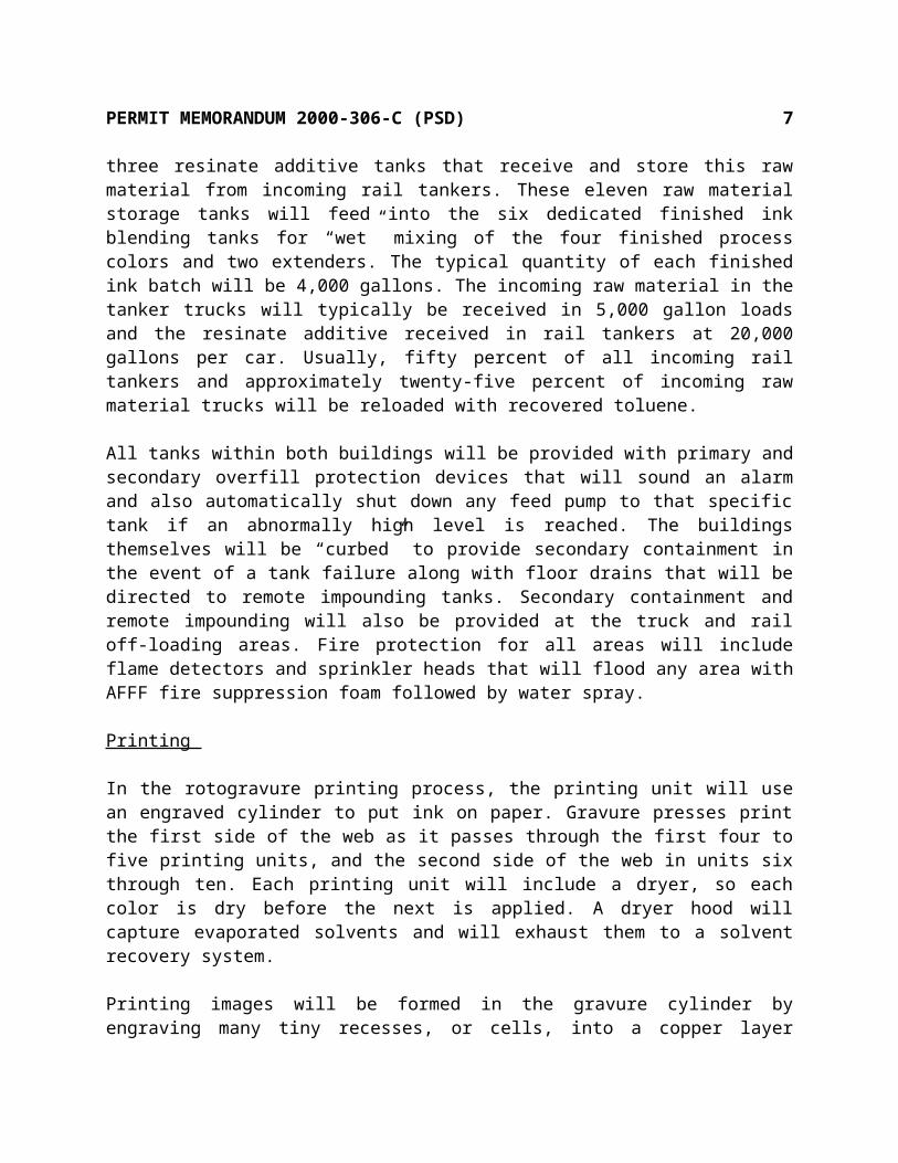
and store this raw material from incoming rail tankers. These eleven raw material storage tanks will feed into the six dedicated finished ink blending tanks for “wet” mixing of the four finished process colors and two extenders. The typical quantity of each finished ink batch will be 4,000 gallons. The incoming raw material in the tanker trucks will typically be received in 5,000 gallon loads and the resinate additive received in rail tankers at 20,000 gallons per car. Usually, fifty percent of all incoming rail tankers and approximately twenty-five percent of incoming raw material trucks will be reloaded with recovered toluene.
All tanks within both buildings will be provided with primary and secondary overfill protection devices that will sound an alarm and also automatically shut down any feed pump to that specific tank if an abnormally high level is reached. The buildings themselves will be “curbed” to provide secondary containment in the event of a tank failure along with floor drains that will be directed to remote impounding tanks. Secondary containment and remote impounding will also be provided at the truck and rail off-loading areas. Fire protection for all areas will include flame detectors and sprinkler heads that will flood any area with AFFF fire suppression foam followed by water spray.
Printing
In the rotogravure printing process, the printing unit will use an engraved cylinder to put ink on paper. Gravure presses print the first side of the web as it passes through the first four to five printing units, and the second side of the web in units six through ten. Each printing unit will include a dryer, so each color is dry before the next is applied. A dryer hood will capture evaporated solvents and will exhaust them to a solvent recovery system.
Printing images will be formed in the gravure cylinder by engraving many tiny recesses, or cells, into a copper layer applied to the cylinder’s surface. After the cylinder is engraved, the copper will be coated with a protective film of chrome to reduce wear on the press.
Cylinders will be about one-fourth submerged in a fountain of low-viscosity mixed ink within each printing unit. The mixed ink will be picked up by the cells on the revolving cylinder surface and will be continuously applied to the paper web. After the impression is made in one unit, the web travels through an enclosed heated air dryer to evaporate the volatile solvent. The web will then be guided along a series of rollers to the next printing unit. Raw ink will sometimes be mixed with related coatings, usually referred to as extenders or varnishes. The ink, as applied, will be a mixture of pigments, binders, varnish, and solvent.
After passing through each of the units, the web will then be slit into ribbons and guided through a series of folders. The folded ribbons will then be cut into individual signatures (pieces) and directed to the automatic stacker bundler for delivery.

PERMIT MEMORANDUM 2000-306-C (PSD) 6
Solvent Recovery
The solvent recovery system will be designed to recover toluene from the drying ovens of the rotogravure printing presses. The system will utilize the adsorption capabilities of activated carbon.
1) SLA (Solvent-Laden Air) Collection: SLA will be collected from presses using one press exhaust fan for each press. SLA discharged from the 8 to 10 drying ovens on each individual press will be manifolded into a main collection duct, where it will enter one of the press exhaust fans. SLA discharged from the press exhaust fans will then be delivered to the main SLA collection duct and drawn to the solvent recovery plant by the SLA fans.
2) SLA Filtration/Cooling: Before entering each fan, the SLA will pass through a pre-filter and a secondary bag filter. The filters will remove particulate matter which would foul the carbon and cooling coils. Coils after each SLA fan will cool the SLA to the optimum adsorption temperature.
3) Adsorption: The filtered and cooled air will be forced by the SLA fans through adsorbers. As the SLA passes through the carbon bed its solvent will be yielded to the activated carbon pellets. The treated air will then be exhausted from the adsorbers to the atmosphere via individual adsorber stacks or a system common stack.
Each system will have up to seven adsorbers and will normally operate with up to six in parallel but staggered cycle adsorption phase, while the remaining adsorber will be steam regenerated. During periods of low SLA flow and/or concentration, the control system will automatically delay the steaming cycle or disable an adsorber. Thus, it will be possible to simultaneously have all seven or fewer adsorbers in adsorption phase.
4) Regeneration: After the activated carbon in an adsorber has become saturated with solvent, it must be regenerated by steam desorption. The adsorber to be steamed will be isolated from the SLA flow by closing its SLA and exhaust valves. The adsorber’s vapor and steam valves will then be opened. As the steam passes through the carbon bed, it will strip the solvent from the carbon pellets and sweep it into the vapor duct. The resulting steam vapor solvent mixture will travel through the vapor duct to the condenser/coolers and possibly an ECOVAP or other heat recovery systems. As the mixture flows through these units, it will be cooled and condensed by cooling tower water.
5) Recovery: Normally, the steam/condensate would flow to a condensing coil to condense the steam into water to allow the solvent to later be decanted. However, to save energy costs the system will possibly be fitted with an Economizing Steam Vapor Loop (ECOVAP) or other heat recovery systems which will include a tube-type exchanger. With the ECOVAP or other heat recovery systems, the steam and solvent will flow through one side of a tower tube type
PERMIT MEMORANDUM 2000-306-C (PSD) 7
heat exchanger. On the other side, makeup water flows. As the makeup water temp rises to about 190o F, it then passes through the ejector and into the steam main feeding the adsorber. Thereby, reducing the steam load of the boiler by two thirds.
The process condensate from the ECOVAP or other heat recovery systems flows to a horizon-tal shell and tube heat exchanger where it is cooled before discharging to the uncondensable bottle tank. Upon leaving the condenser/coolers, the condensed fluids pass on to system in-condensable vapors. A standpipe in each separator maintains the proper liquid level in each condenser/cooler.
The incondensable bottle tanks also separate incondensable gas from the condensate. This gas is recycled back through the incondensable duct to the SLA suction duct. The condensate then flows to the system decanter. The decanter continuously separates the process condensate into organic and aqueous layers. The lighter organic solvent rises and overflows through a collecting funnel and passes on to the solvent tank. The heavier aqueous phase sinks to the bottom of its system decanter. It then flows into the system condensate tank.
Finishing
Finished products from both printing processes will be sent to Finishing for assembly. Assembly will be performed in the Oklahoma City plant through the use of saddle stitchers and perfect binders.
Saddle Stitchers
A saddle stitcher is a machine designed to manufacture magazines (e.g., L.L. Bean) that are bound together with wire (stitches). A saddle stitcher, on average, has between 8 and 40 hoppers that feed signatures onto a moving gathering chain. Signatures can range, on average, from 4 pages to 32 pages, and may include a variety of cards or order forms.
Beginning with the centermost signature in the book, a hopper opens the signature and delivers it to the chain. The gathering chain carries it to the next hopper, which delivers the next signature on top of the first, continuing until the cover (the outermost signature) is applied.
Once all signatures are collated or gathered, the book is measured for proper thickness to determine if there are extra or missing pages. If the thickness is correct, the gathered signatures are considered a good book. Good books will be stitched with 3 wires, bad books will be rejected without stitching. The good books will continue through the machine to the trimmer. The trimmer cuts the head, foot, and face of the book (all three sides EXCEPT the backbone) to get a smooth, square book. After pre or post trimming, an address may be applied either by preprinted paper label, or via an inline inkjet printer.

PERMIT MEMORANDUM 2000-306-C (PSD) 8
Books will then be delivered to a stacker, which piles the books into bundles. Bundles are strapped by an automatic strapper and wrapped in plastic. The wrapped bundle of books travels through a heat tunnel to shrink the plastic to the size of the bundle, delivering a complete package to the end of the line where books are bagged or palletized for delivery.
Perfect Binders
A perfect binder is a machine designed to manufacture magazines that are bound together with glue (e.g., National Geographic). A perfect binder, on average, has between 20 and 54 hoppers that feed signatures into a raceway. Signatures can range, on average, from 2 pages to 32 pages, and may include a variety of cards or order forms.
Signatures are moved along the raceway by a chain. Beginning with the front of the book (or the back of the book in some cases), signatures are fed into the raceway, each signature dropping onto the previous one, building the book until all pages have been added except the cover.
Each signature is verified at the individual hopper for proper thickness, if each signature in a given book is determined to be the proper thickness, the gathered signatures are considered a good book. Bad books are rejected. Good books enter the carousel.
As the book travels around the carousel, the backbones of all signatures are sawed off, exposing each page (even those that were previously ‘nested’ between the outermost pages of a signature). After sawing, a hot melt adhesive is applied to the sawed portion of the book, and a cover is applied.
The books leave the carousel and travel along a conveyor to allow the hot melt to cool before entering the trimmer. The trimmer cuts the head, foot, and face of the book (all three sides EXCEPT the backbone) to get a smooth, square book. After trimming, an address may be applied either by preprinted paper label, or via an inline inkjet printer.
Books will then be delivered to a stacker, which piles the books into bundles. Bundles are strapped by an automatic strapper and wrapped in plastic. The wrapped bundle of books travels through a heat tunnel to shrink the plastic to the size of the bundle, delivering a complete package the end of the line where books are bagged or palletized for delivery.
Ink-Jet
Quad’s saddle stitchers and perfect binders will be equipped with multiple Ink Jet stations. These stations will make it possible to Ink Jet an unlimited number of personalized messages, addresses, and marketing codes parallel and/or perpendicular to the spine on the inside pages or cover of each printed piece.

PERMIT MEMORANDUM 2000-306-C (PSD) 9
The Ink Jet print head works on the principle that tiny drops of ink with electrostatic charges can be deflected in flight by an electrostatic field. This requires the following basic components:
1) A gun body fitted with a very fine nozzle. The gun body contains pressurized ink which emerges from the nozzle as a thin jet. The gun nozzle also contains a drive rod, which vibrates ultrasonically. Pressure waves set up in the ink by the vibrating drive rod make the Ink Jet break up into separate drops soon after leaving the nozzle.
2) A charge electrode which surrounds the Ink Jet at the point where it breaks up into drops. The voltage on the charge electrode at the moment a drop breaks off gives the drop a particular electrostatic charge.
3) Deflector plates, which are maintained at two very high opposing voltages. The resulting electrostatic field deflects the drops as they pass between the plates.
4) A gutter which collects all the ink drops not used for printing. These are returned to the ink supply.
The deflector plates are maintained at fixed voltages which are positive, negative, positive, negative, etc. The drops in the first Ink Jet are charged positively. The drops in the next Ink Jet are charged negatively. This sequence is repeated through all the Ink Jets. The result is that the ink drops in all jets are deflected in the same direction when they pass between the deflector plates.
The amount of deflection between the plates depends upon the charge on the ink drop. The charge electrode, is therefore, fed with a succession of carefully controlled voltages, timed to give each ink drop an individual charge. The succession of ink drops are deflected according to their charges and land on the print surface in vertical lines or strokes. The strokes are separated by the sideways movement of the print surface (i.e. the product moving past the print head). The patterns of dots in the strokes then make up the printed character.
Quad’s patented Ink Jet Solvent Recovery System (SRS) will capture and reuse approximately 60% of the VOCs (volatile organic compounds) associated with this process resulting in a safer and healthier work environment. The VOCs include MEK (methyl ethyl ketone), isopropyl alcohol, and methanol.
The system will consist of a closed loop ink supply tank system which directs solvent vapors discharged from the tank through a vent tube. The vent tube will be connected to a condenser which cools the vapors so nearly all the solvent is condensed. The condensed vapors and ink will then be returned via the vent tube to the ink supply tank. This closed-loop system eliminates the need for external exhaust systems that remove hazardous air pollutants.
SECTION III. EQUIPMENT

PERMIT MEMORANDUM 2000-306-C (PSD) 10
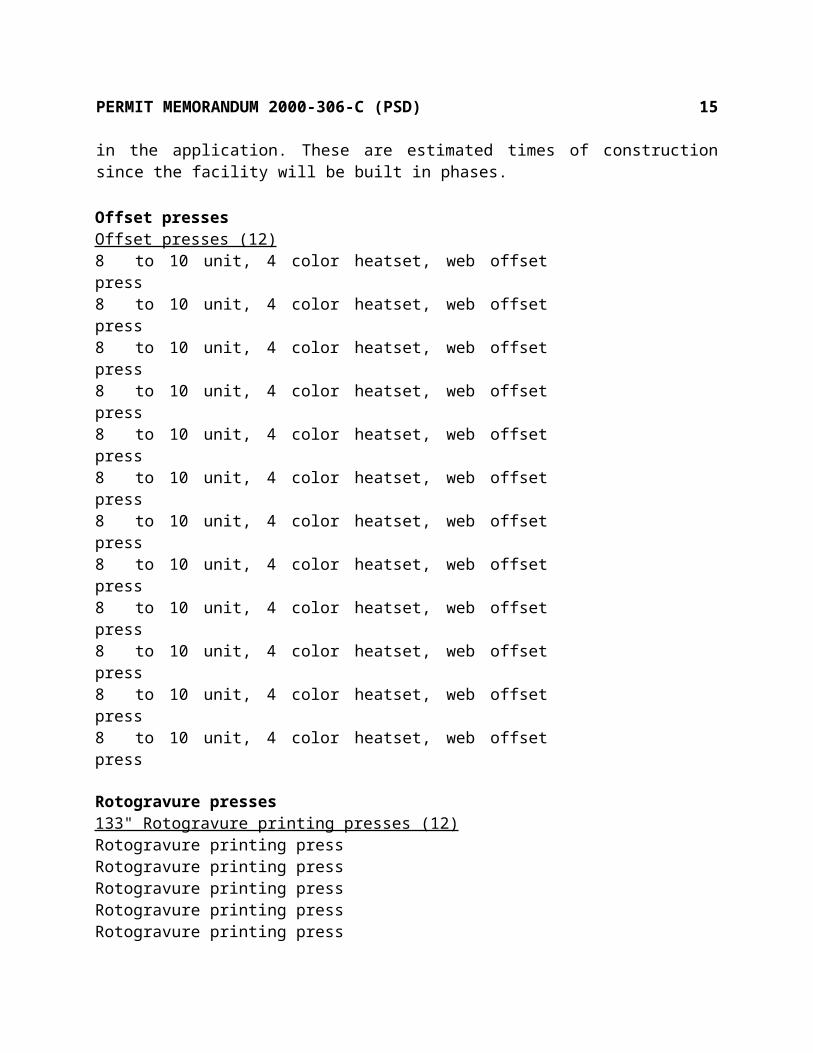
The following is a list of equipment which will be required by the Quad/Graphics facility. Several construction dates are listed in the application. These are estimated times of construction since the facility will be built in phases.
Offset pressesOffset presses (12)8 to 10 unit, 4 color heatset, web offset press8 to 10 unit, 4 color heatset, web offset press8 to 10 unit, 4 color heatset, web offset press8 to 10 unit, 4 color heatset, web offset press8 to 10 unit, 4 color heatset, web offset press8 to 10 unit, 4 color heatset, web offset press8 to 10 unit, 4 color heatset, web offset press8 to 10 unit, 4 color heatset, web offset press8 to 10 unit, 4 color heatset, web offset press8 to 10 unit, 4 color heatset, web offset press8 to 10 unit, 4 color heatset, web offset press8 to 10 unit, 4 color heatset, web offset press
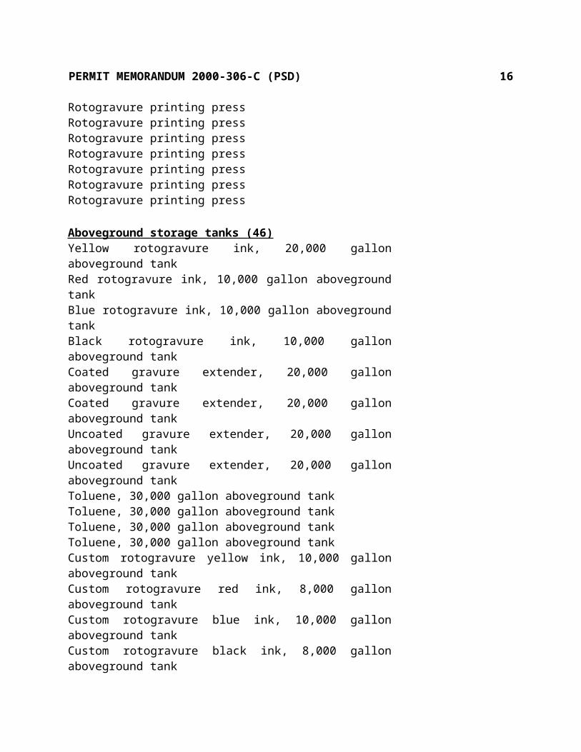
Rotogravure presses133" Rotogravure printing presses (12)Rotogravure printing pressRotogravure printing pressRotogravure printing pressRotogravure printing pressRotogravure printing pressRotogravure printing pressRotogravure printing pressRotogravure printing pressRotogravure printing pressRotogravure printing pressRotogravure printing pressRotogravure printing press
Aboveground storage tanks (46)Yellow rotogravure ink, 20,000 gallon aboveground tankRed rotogravure ink, 10,000 gallon aboveground tankBlue rotogravure ink, 10,000 gallon aboveground tankBlack rotogravure ink, 10,000 gallon aboveground tankCoated gravure extender, 20,000 gallon aboveground tankCoated gravure extender, 20,000 gallon aboveground tankUncoated gravure extender, 20,000 gallon aboveground tankUncoated gravure extender, 20,000 gallon aboveground tank

PERMIT MEMORANDUM 2000-306-C (PSD) 11
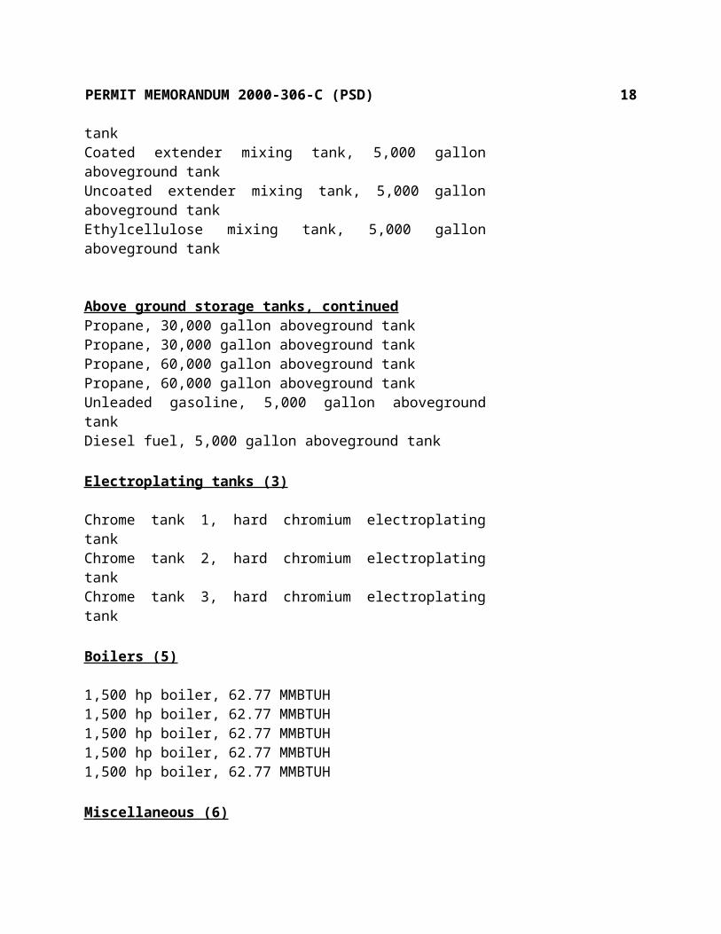
Toluene, 30,000 gallon aboveground tankToluene, 30,000 gallon aboveground tankToluene, 30,000 gallon aboveground tankToluene, 30,000 gallon aboveground tankCustom rotogravure yellow ink, 10,000 gallon aboveground tankCustom rotogravure red ink, 8,000 gallon aboveground tankCustom rotogravure blue ink, 10,000 gallon aboveground tankCustom rotogravure black ink, 8,000 gallon aboveground tankCustom rotogravure coated extender, 10,000 gallon aboveground tankYellow concentrate, ink blending, 12,000 gallon tankRubine red concentrate, ink blending, 10,000 gallon tankBarium lithol, ink blending, 8,000 gallon tankCyan blue concentrate, ink blending, 10,000 gallon tankAlkali blue concentrate, ink blending, 350 gallon totesMilori blue concentrate, ink blending, 350 gallon totesBlack concentrate, ink blending, 10,000 gallon tankClay concentrate, ink blending, 20,000 gallon tankEthylcellulose compound, ink blending, 10,000 gallon tankWax, ink blending, 10,000 gallon tankResinate MR560, R1A, ink blending, 30,000 gallon tankResinate MR560, R1B, ink blending, 30,000 gallon tankJonrez MR 522, ink blending, 30,000 gallon tankJonrez MR 522, ink blending, 30,000 gallon tankOffset blanket wash, 5,000 gallon aboveground tankOffset auto blanket wash, 2,500 gallon aboveground tankYellow ink mixing tank, 5,000 gallon aboveground tankRed ink mixing tank, 5,000 gallon aboveground tankBlue ink mixing tank, 5,000 gallon aboveground tankBlack ink mixing tank, 5,000 gallon aboveground tankCoated extender mixing tank, 5,000 gallon aboveground tankUncoated extender mixing tank, 5,000 gallon aboveground tankEthylcellulose mixing tank, 5,000 gallon aboveground tank
Above ground storage tanks, continuedPropane, 30,000 gallon aboveground tankPropane, 30,000 gallon aboveground tankPropane, 60,000 gallon aboveground tankPropane, 60,000 gallon aboveground tankUnleaded gasoline, 5,000 gallon aboveground tankDiesel fuel, 5,000 gallon aboveground tank
Electroplating tanks (3)

PERMIT MEMORANDUM 2000-306-C (PSD) 12
Chrome tank 1, hard chromium electroplating tankChrome tank 2, hard chromium electroplating tankChrome tank 3, hard chromium electroplating tank
Boilers (5)
1,500 hp boiler, 62.77 MMBTUH1,500 hp boiler, 62.77 MMBTUH1,500 hp boiler, 62.77 MMBTUH1,500 hp boiler, 62.77 MMBTUH1,500 hp boiler, 62.77 MMBTUH
Miscellaneous (6)
Offset press fugitive emission stack (solvents)Ink Jet fugitive emission stack (solvents)Cold cleanerDrum proof press 1Drum proof press 2Drum proof press 3Loading operations
SECTION IV. EMISSIONS
Emissions calculations are grouped as shown in the previous section with all factors and assumptions described. All chemicals listed with an asterisk are considered a Hazardous Air Pollutant (HAP).
a) Offset Presses
Each press may process two webs of paper at the same time. As each web passes through a press it will apply ink according to the settings of the press. After the ink is applied, the web will continue to one of two dryer/oxidizers or a combined centralized system. No evaporation, or very insignificant amounts based on the low average vapor pressure of the inks, 1.1 psi, occurs until the web enters an integrated dryer/thermal oxidizer where heat will be used to dry the ink. Each drying area will be considered to have 100% capture efficiency based on a review done by the state of Wisconsin with input from EPA, Region V and EPA, OAQPS, since each will be operated under a ½ inch negative water column pressure and with no visible emissions directly attributable to the press or dryer and is integrated with the oxidizer. The EPA draft document

PERMIT MEMORANDUM 2000-306-C (PSD) 13
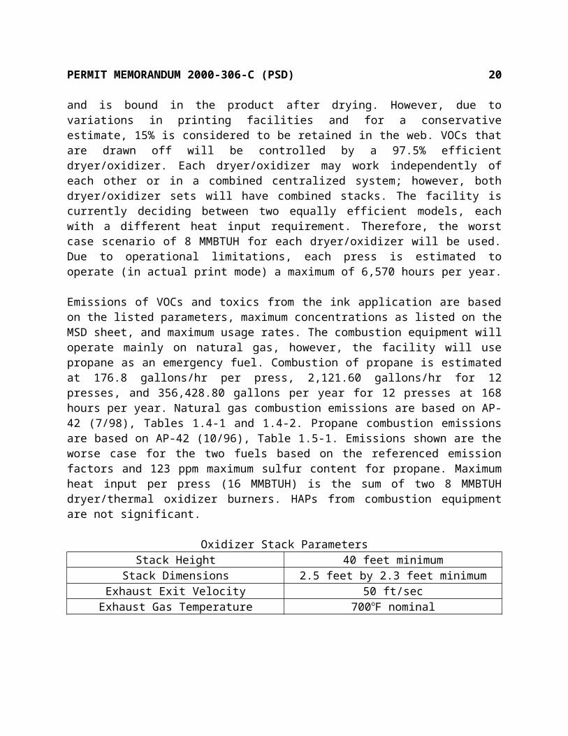
“Control of Volatile Organic Compounds Emissions from Offset Lithographic Printing” (September 1993) and AP-42 Section 4.9 (4/81), indicates 20 to 40% of the solvent remains and is bound in the product after drying. However, due to variations in printing facilities and for a conservative estimate, 15% is considered to be retained in the web. VOCs that are drawn off will be controlled by a 97.5% efficient dryer/oxidizer. Each dryer/oxidizer may work independently of each other or in a combined centralized system; however, both dryer/oxidizer sets will have combined stacks. The facility is currently deciding between two equally efficient models, each with a different heat input requirement. Therefore, the worst case scenario of 8 MMBTUH for each dryer/oxidizer will be used. Due to operational limitations, each press is estimated to operate (in actual print mode) a maximum of 6,570 hours per year.
Emissions of VOCs and toxics from the ink application are based on the listed parameters, maximum concentrations as listed on the MSD sheet, and maximum usage rates. The combustion equipment will operate mainly on natural gas, however, the facility will use propane as an emergency fuel. Combustion of propane is estimated at 176.8 gallons/hr per press, 2,121.60 gallons/hr for 12 presses, and 356,428.80 gallons per year for 12 presses at 168 hours per year. Natural gas combustion emissions are based on AP-42 (7/98), Tables 1.4-1 and 1.4-2. Propane combustion emissions are based on AP-42 (10/96), Table 1.5-1. Emissions shown are the worse case for the two fuels based on the referenced emission factors and 123 ppm maximum sulfur content for propane. Maximum heat input per press (16 MMBTUH) is the sum of two 8 MMBTUH dryer/thermal oxidizer burners. HAPs from combustion equipment are not significant.
Oxidizer Stack ParametersStack Height 40 feet minimum
Stack Dimensions 2.5 feet by 2.3 feet minimumExhaust Exit Velocity 50 ft/sec
Exhaust Gas Temperature 700oF nominal
Offset PressesMaximum annual operating hours per press 6,570 (actual print mode)Maximum annual ink usage for 12 presses 15,840,000 lbsMaximum hourly ink usage for 12 presses 2410.96 lbsCapture efficiency for dryer/oxidizer 100%Minimum oxidizer efficiency 97.50%Percentage of solvent in ink 44.00%Percentage of solvent retained in ink 15.00%
VOC and Toxic EmissionsMaximum Maximum Usage Emissions

PERMIT MEMORANDUM 2000-306-C (PSD) 14
Product CAS # % Content lb/yr lb/hr TPYHeat-Set Printing Ink 15,840,000VOC 44% 6,969,600 22.54 74.05Hydrocarbon Petroleum Distillates 8042-47-5 44% 6,969,600 22.54 74.05Hydrocarbon Petroleum Distillates 64742-46-7 44% 6,969,600 22.54 74.05
Combustion Emissions per Offset Press (16 MMBTUH)Emission Factors Emissions
Pollutant Gas, lb/mmscf Propane, lb/gallon lb/hr TPYNOx 100 0.014 2.48 5.23CO 84 0.0019 1.32 4.33VOC 5.5 0.00049 0.09 0.28PM10 7.6 0.0004 0.12 0.39SO2 0.6 0.00142 0.25 0.05
Total Combustion Emissions for 12 Offset PressesEmission Factors Emissions
Pollutant Gas, lb/mmscf Propane, lb/gallon lb/hr TPYNOx 100 0.014 29.76 62.76CO 84 0.0019 15.81 51.94VOC 5.5 0.00049 1.04 3.40PM10 7.6 0.0004 1.43 4.70SO2 0.6 0.00142 3.00 0.60
b) Rotogravure Presses
The majority of emissions will result from drying the ink in each of the dryers. Emissions will also result from the ink fountain, exposed parts of the gravure cylinder, the paper path at the dryer inlet, and from the paper web after exiting the dryers between printing units. All solvent laden air will be captured and ducted to adsorbers which will be accomplished by use of permanent total enclosures. Each total enclosure may be press specific, individual pressroom, or entire pressroom. AP-42 indicates that 3 to 4 percent of the total solvent will be retained in the web after drying and emitted as a fugitive. With a 100% capture efficiency, highly efficient adsorbers (>98%), and accounting for 3% solvents retained in the web and emitted as fugitives the overall “system” will have a minimum efficiency of 95%.
PERMIT MEMORANDUM 2000-306-C (PSD) 15
Emissions of VOCs and HAPs/toxics from the ink application are based on an overall “system” efficiency of 95%, maximum concentrations as listed on the MSD sheets, and the maximum usage rates. Inks will regularly require the addition of extenders. These are accounted for in the listed maximum concentrations. Emissions from each press will be ducted to a carbon adsorber. The carbon adsorbers will be divided into sets of up to six with emissions flowing into a header system and eventually exiting a main stack. No combustion emissions result from the dryers since the heat will be provided by boilers. These emissions will be reviewed separately.
Main Stacks (2)Stack Height 37 feet minimum
Stack Diameter 11 feetExhaust Exit Velocity per Adsorber 11.40 ft/sec*
Exhaust Gas Temperature 80oF nominal* flow for each adsorber, 68.40 ft/sec when six presses running
VOC and HAP*/Toxic Emissions
Product CAS #Maximum % Content
Maximum Usage Emissionsgal/hr gal/yr lb/hr TPY
Yellow (8.24 lb/gal) 939.12 6,170,016VOC 61.67 238.61 783.84Toluene* 108-88-3 55 212.80 699.06Xylene* 1330-20-7 0.42 1.63 5.34Ethylbenzene* 100-41-4 0.14 0.54 1.78Light Aliphatic Naphtha 64742-89-8 6.10 23.60 77.53
Product CAS #Maximum % Content
Maximum Usage Emissionsgal/hr gal/yr lb/hr TPY
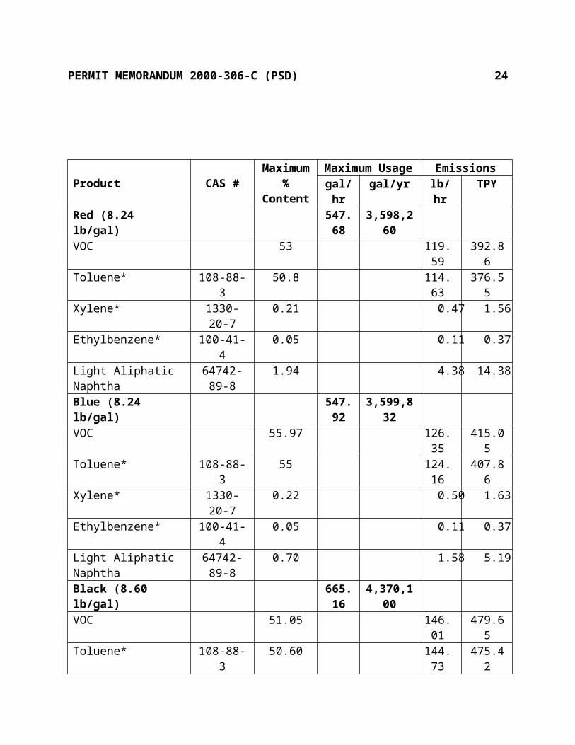
Red (8.24 lb/gal) 547.68 3,598,260VOC 53 119.59 392.86Toluene* 108-88-3 50.8 114.63 376.55Xylene* 1330-20-7 0.21 0.47 1.56Ethylbenzene* 100-41-4 0.05 0.11 0.37Light Aliphatic Naphtha 64742-89-8 1.94 4.38 14.38Blue (8.24 lb/gal) 547.92 3,599,832VOC 55.97 126.35 415.05Toluene* 108-88-3 55 124.16 407.86Xylene* 1330-20-7 0.22 0.50 1.63
PERMIT MEMORANDUM 2000-306-C (PSD) 16
Ethylbenzene* 100-41-4 0.05 0.11 0.37Light Aliphatic Naphtha 64742-89-8 0.70 1.58 5.19Black (8.60 lb/gal) 665.16 4,370,100VOC 51.05 146.01 479.65Toluene* 108-88-3 50.60 144.73 475.42Xylene* 1330-20-7 0.07 0.20 0.66Ethylbenzene* 100-41-4 0.02 0.06 0.19Light Aliphatic Naphtha 64742-89-8 0.35 1.00 3.29
ChemicalCAS
NumberTotal Emissionslb/hr TPY
VOC 630.56 2071.40HAPs - 1970.79Toluene* 108-88-3 596.32 1958.89Xylene* 1330-20-7 2.80 9.19Ethylbenzene* 100-41-4 0.82 2.71Light Aliphatic Naphtha 64742-89-8 30.56 100.39
c) Storage Tanks
Rotogravure Ink Aboveground Storage Tanks
Emissions will result from the listed throughputs for each tank. Emissions from each tank will be ducted to one of the Rotogravure press carbon adsorbers with 98% efficiency. Emissions are based on the proposed throughputs and the EPA Tanks4.0 program. For a conservative estimate and ease of modeling, all throughput is estimated as toluene. HAP/Toxic emissions from the ink tanks are based on the highest percent contained in any ink or extender.
Tank Number Material Size, gallons Throughput, gallonsT-01 Yellow Rotogravure Ink 20,000 3,702,011T-02 Red Rotogravure Ink 10,000 2,158,955T-03 Blue Rotogravure Ink 10,000 2,159,901T-04 Black Rotogravure Ink 10,000 3,496,081T-05 Coated Rotogravure Extender 20,000 2,115,230T-06 Coated Rotogravure Extender 20,000 2,115,230T-07 Uncoated Rotogravure Extender 20,000 995,402T-08 Uncoated Rotogravure Extender 20,000 995,402T-09 Toluene and Recovered Toluene 30,000 4,644,442T-10 Toluene and Recovered Toluene 30,000 4,644,442T-11 Toluene and Recovered Toluene 30,000 4,644,442T-12 Toluene and Recovered Toluene 30,000 4,644,442

PERMIT MEMORANDUM 2000-306-C (PSD) 17
VOC EmissionsTank lb/hr TPYT-01 0.002 0.01T-02 0.002 0.007T-03 0.002 0.007T-04 0.005 0.02T-05 0.001 0.006T-06 0.001 0.006T-07 0.001 0.005T-08 0.001 0.005T-09 0.002 0.008T-10 0.002 0.008T-11 0.002 0.008T-12 0.002 0.008
TOTAL 0.023 0.098
Total EmissionsChemical % of Total VOC lb/hr TPY
VOC - 0.023 0.098HAPs - - 0.098
Toluene* 98 0.02 0.096Xylene* 0.42 0.001 0.001
Ethylbenzene* 0.14 0.001 0.001Light Aliphatic Naphtha 6.10 0.001 0.006
Custom Rotogravure Ink Aboveground Storage Tanks
These tanks will store inks for specific customers. The HAP/VOC constituent will be the same as for the other inks, therefore, the emission estimates are based on the same methodology. These tanks will also be vented to the carbon adsorbers.
Tank Number Material Size, gallons Throughput, gallonsT-13 Yellow Rotogravure Ink 10,000 180,233T-14 Red Rotogravure Ink 8,000 93,750T-15 Blue Rotogravure Ink 10,000 187,500T-16 Black Rotogravure Ink 8,000 120,000T-17 Coated Rotogravure Extender 10,000 258,073
VOC EmissionsTank lb/hr TPY
PERMIT MEMORANDUM 2000-306-C (PSD) 18
T-13 0.001 0.002T-14 0.001 0.001T-15 0.001 0.002T-16 0.001 0.001T-17 0.001 0.003
TOTAL 0.005 0.009
Total EmissionsChemical % of Total VOC lb/hr TPY
VOC - 0.005 0.009HAPs - - 0.009
Toluene* 98 0.005 0.009Xylene* 0.42 0.00001 0.0001
Enthylbenzene* 0.14 0.00001 0.00001Light Aliphatic Naphtha 6.10 0.0003 0.001
Rotogravure Ink Blending Aboveground Storage Tanks
These tanks will store materials required for the facility to blend and produce inks on-site. Since the facility will be recycling the solvents, on-site blending reduces transportation both to and from a blending facility. Emissions are based on the same methodology as previously described (i.e., maximum throughput, total throughput as toluene, emissions ducted to carbon adsorbers, and maximum speciation).
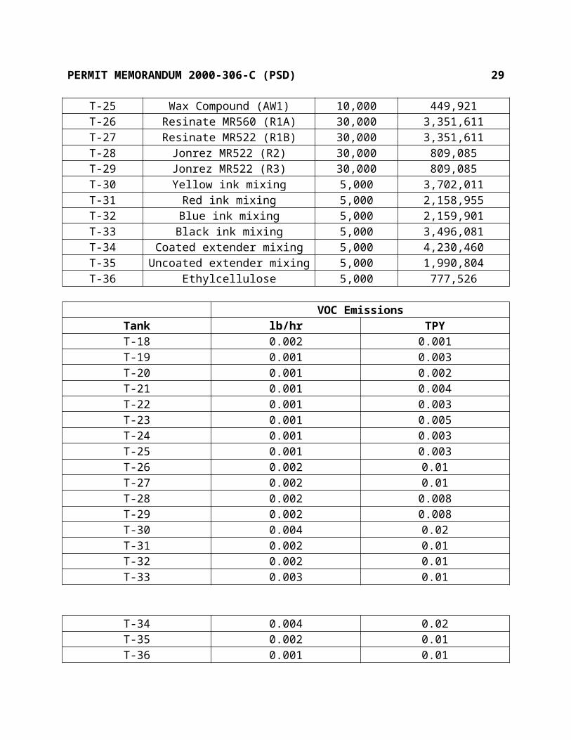
Tank Number Material Size, gallons Throughput, gallonsT-18 Yellow Concentrate (CY1) 12,000 1,295,742T-19 Rubine Red Concentrate (CR1) 10,000 677,334T-20 Barium Lithol Concentrate (CR2) 8,000 420,050T-21 Blue Concentrate (CB1) 10,000 893,039T-22 Black Concentrate (CK1) 10,000 838,836T-23 Clay Concentrate (AC1) 20,000 852,055T-24 Ethyl Cellulose Compound (AEC1) 10,000 777,526T-25 Wax Compound (AW1) 10,000 449,921T-26 Resinate MR560 (R1A) 30,000 3,351,611T-27 Resinate MR522 (R1B) 30,000 3,351,611T-28 Jonrez MR522 (R2) 30,000 809,085T-29 Jonrez MR522 (R3) 30,000 809,085T-30 Yellow ink mixing 5,000 3,702,011T-31 Red ink mixing 5,000 2,158,955T-32 Blue ink mixing 5,000 2,159,901

PERMIT MEMORANDUM 2000-306-C (PSD) 19
T-33 Black ink mixing 5,000 3,496,081T-34 Coated extender mixing 5,000 4,230,460T-35 Uncoated extender mixing 5,000 1,990,804T-36 Ethylcellulose 5,000 777,526
VOC EmissionsTank lb/hr TPYT-18 0.002 0.001T-19 0.001 0.003T-20 0.001 0.002T-21 0.001 0.004T-22 0.001 0.003T-23 0.001 0.005T-24 0.001 0.003T-25 0.001 0.003T-26 0.002 0.01T-27 0.002 0.01T-28 0.002 0.008T-29 0.002 0.008T-30 0.004 0.02T-31 0.002 0.01T-32 0.002 0.01T-33 0.003 0.01
T-34 0.004 0.02T-35 0.002 0.01T-36 0.001 0.01
TOTAL 0.035 0.15
Total EmissionsChemical % of Total VOC lb/hr TPY
VOC - 0.035 0.15HAPs - - 0.15
Toluene* 98 0.034 0.15Xylene* 0.42 0.001 0.001
Ethylbenzene* 0.14 0.001 0.001Light Aliphatic Naphtha 6.10 0.002 0.009
Offset Press Solvent Aboveground Storage Tanks
Products stored in these tanks is for offset press miscellaneous cleaning and cleaning of print blankets. The stored materials consist mainly of aromatic and aliphatic hydrocarbons. However,
PERMIT MEMORANDUM 2000-306-C (PSD) 20
1,2,4 Trimethylbenzene is contained in both materials and is, therefore, used as a worst case scenario to estimate emissions using the EPA Tanks4.0 program. Estimated emissions are insignificant, as shown, based on the proposed throughputs.
Tank Number Material Size, gallons Throughput, gallonsT-37 Manual Blanket Wash 5,500 49,560T-38 Automatic Blanket Wash 2,500 25,560
VOC EmissionsTank lb/hr TPYT-37 0.001 0.003T-38 0.001 0.003
TOTAL 0.002 0.006
Propane Aboveground Storage Tanks
Four propane storage tanks will be located on-site for forklift operations and back-up fuel. All tanks will be pressurized between 50 and 150 psi, therefore, emissions will be negligible.
Tank Number Material Size, gallonsT-39 Propane 30,000T-40 Propane 30,000T-41 Propane 60,000T-42 Propane 60,000
Gasoline and Diesel Aboveground Storage Tanks
These tanks will be used for fueling fleet and distribution vehicles. Emissions are based on the listed throughputs and the EPA Tanks4.0 program.
Tank Number Material Size, gallons Throughput, gallonsT-43 Unleaded Gasoline 5,000 793,875T-44 Diesel Fuel 5,000 793,875
VOC EmissionsTank lb/hr TPYT-43 0.38 1.67T-44 0.001 0.005
TOTAL 0.381 1.675
d) Electroplating Tanks

PERMIT MEMORANDUM 2000-306-C (PSD) 21
The facility will consist of three hexavalent hard chromium electroplating tanks. Each tank will have a collection hood placed at the rear and top of the tank. This placement will allow the hood to collect only those fumes most likely to escape from the tank and will allow the heavier droplets to fall back into the plating solution. Connected to the hood will be a wet scrubber with a controlling fan. When plating operations are performed, the fan will run at maximum operational capacity or 1,500 SCFM airflow. However, when plating is not being performed, the fan will run at a lower speed to reduce energy consumption while still providing continuous exhaust from the tank. The wet scrubber will consist of a water spray directed onto a filter media and a mist eliminator pad for a removal efficiency of 95% to 99%.
Emission limits are based on the 40 CFR Part 63, Subpart N, limit of 0.015 mg/dscm, the listed design parameters for the tanks, and 5,200 operating hours per tank. Recent testing at a similar facility indicates the facility will comply with the limits.
Tank Parameters, Each of 3Square Feet of Surface Area 39.58
Design Air Flow per Square Foot of Surface Area in Cubic Feet 250Total Flow in dscm per hour 16,809
Emissions in mg/hr 252.14Emissions in lb/hr 0.00056
Stack Parameters, Each of 3Stack Height, ft 9 minimumStack Diameter, in 10Stack Exhaust Flow, CFM 9,200Stack Exhaust Temperature, oF 85 nominal
Chromium VI EmissionsTank lb/hr TPYCT-1 0.00056 0.0015CT-2 0.00056 0.0015CT-3 0.00056 0.0015
TOTAL 0.00168 0.0045
e) Boiler Operations
The facility will contain five 62.77 MMBTUH (1,500 HP) boilers. The boilers will be used to provide steam for the rotogravure press dryers and for comfort heat. The boilers will be equipped with low NOx burners and flue gas recirculation. The boilers will fire mainly on

PERMIT MEMORANDUM 2000-306-C (PSD) 22
natural gas, however, for emergency situations each boiler will be permitted to burn propane for 336 hours per year or 233,030.39 gallons per year.
Combustion of propane is estimated at a maximum of 693.54 gallons/hr per boiler, 3,467.70 gallons/hr for 5 boilers, and 1,165,151.95 gallons per year for 5 boilers at 336 hours per year. Natural gas combustion emissions are based on manufacturer’s data, natural gas heat value of 1,020 btu/cf, and maximum firing rate of 62.77 MMBTUH. Propane combustion emissions are based on manufacturer’s data, 90,500 btu/gal, and 123 ppm maximum sulfur content for propane. Emissions shown are the worse case for the two fuels based on the referenced emission factors. HAP emissions are based on AP-42 (7/98) Table 1.4-3. Only significant HAP emissions are shown.
Stack Parameters For Each BoilerStack Height 70 ft minimum
Stack Diameter 41 inchesExit Velocity 33.71 ft/sec (@ 100% firing rate)Temperature 383o F (@ 100% firing rate) nominal
Combustion Emissions per Boiler (62.77 MMBTUH)Emission Factors Emissions
Pollutant Gas, lb/mmbtu Propane, lb/mmbtu lb/hr TPYNOx 0.035 0.150 9.42 10.84CO 0.038 0.070 4.39 10.81VOC 0.016 0.008 1.00 4.38PM10 0.01 0.001 0.63 2.76SO2 0.001 0.016 1.00 0.42
Total Combustion Emissions for 5 BoilersEmission Factors Emissions
Pollutant Gas, lb/mmscf Propane, lb/gallon lb/hr TPYNOx 0.035 0.019 47.10 54.20CO 0.038 0.0032 21.95 54.05VOC 0.016 0.00049 5.00 21.90PM10 0.01 0.0004 3.15 13.80SO2 0.001 0.00142 5.00 2.10Hexane* 1.8 - 0.55 2.41Formaldehyde* 0.075 - 0.02 0.09

PERMIT MEMORANDUM 2000-306-C (PSD) 23
Benzene* 0.0021 - 0.001 0.004Toluene* 0.0034 - 0.001 0.004
f) Miscellaneous
Offset Press Operation Solvent Fugitive Emissions
Several solvents will be used in the offset operations including fountain solution, blanket washes, and miscellaneous cleanup solvents. Fountain solutions will be used for proper application of inks on the plates, however, these will not be applied to the web. Manual and auto blanket washes will be used to wash or clean the blankets. Miscellaneous solvent will be used for equipment cleaning, mostly during equipment downtime.
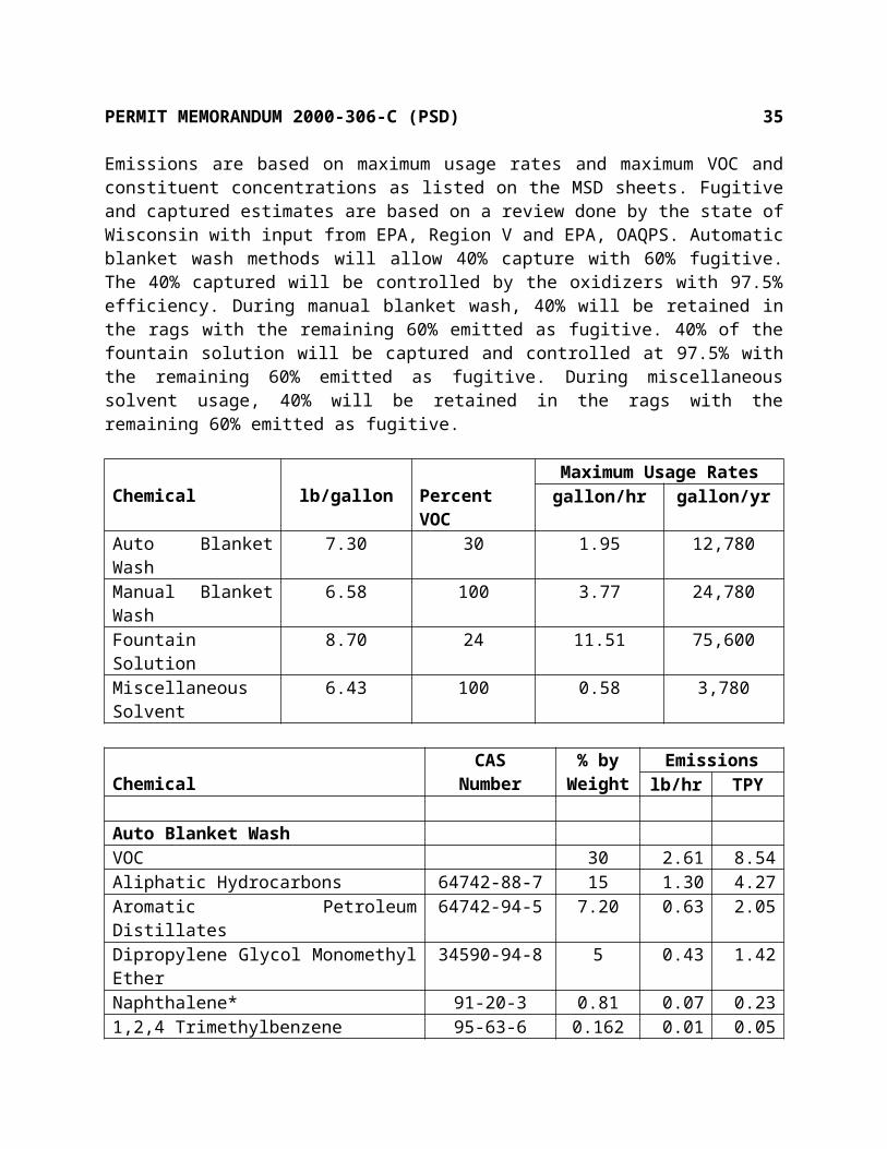
Emissions are based on maximum usage rates and maximum VOC and constituent concentrations as listed on the MSD sheets. Fugitive and captured estimates are based on a review done by the state of Wisconsin with input from EPA, Region V and EPA, OAQPS. Automatic blanket wash methods will allow 40% capture with 60% fugitive. The 40% captured will be controlled by the oxidizers with 97.5% efficiency. During manual blanket wash, 40% will be retained in the rags with the remaining 60% emitted as fugitive. 40% of the fountain solution will be captured and controlled at 97.5% with the remaining 60% emitted as fugitive. During miscellaneous solvent usage, 40% will be retained in the rags with the remaining 60% emitted as fugitive.
Chemical lb/gallon Percent VOCMaximum Usage Rates
gallon/hr gallon/yrAuto Blanket Wash 7.30 30 1.95 12,780Manual Blanket Wash 6.58 100 3.77 24,780Fountain Solution 8.70 24 11.51 75,600Miscellaneous Solvent 6.43 100 0.58 3,780
ChemicalCAS
Number% by
WeightEmissions
lb/hr TPY
Auto Blanket WashVOC 30 2.61 8.54Aliphatic Hydrocarbons 64742-88-7 15 1.30 4.27Aromatic Petroleum Distillates 64742-94-5 7.20 0.63 2.05Dipropylene Glycol Monomethyl Ether 34590-94-8 5 0.43 1.42Naphthalene* 91-20-3 0.81 0.07 0.231,2,4 Trimethylbenzene 95-63-6 0.162 0.01 0.05
Manual Blanket WashVOC 100 14.89 48.92
PERMIT MEMORANDUM 2000-306-C (PSD) 24
Aliphatic Hydrocarbons 64742-95-6 87.3 13.00 42.71Aromatic Petroleum Distillates 8052-41-3 9 1.34 4.401,2,4 Trimethylbenzene 95-63-6 2.6 0.39 1.27Xylene* 1330-20-7 1.1 0.16 0.54
Fountain SolutionVOC 24 14.66 48.15Butyl Carbitol* 112-34-5 3.5 2.14 7.02Acetic Acid 64-19-7 8.16 4.98 16.37Dipropylene Glycol Monomethyl Ether 34590-94-8 12 7.33 24.07
Miscellaneous SolventVOC 100 2.24 7.29Aliphatic Petroleum Distillates 64742-89-8 60 1.34 4.37Ethyl Acetate 141-78-6 5 0.11 0.36Isopropanol 67-63-0 30 0.67 2.19Methyl Ethyl Ketone* 78-93-3 9 0.20 0.66Xylene* 1330-20-7 4.60 0.10 0.34Ethylbenzene* 100-41-4 1.20 0.03 0.09
ChemicalCAS
NumberTotal Emissionslb/hr TPY
VOC 34.39 112.89HAPs - 8.87Aliphatic Hydrocarbons 64742-88-7 1.30 4.27Aromatic Petroleum Distillates 64742-94-5 0.63 2.05Dipropylene Glycol Monomethyl Ether 34590-94-8 7.76 25.49Naphthalene* 91-20-3 0.07 0.231,2,4 Trimethylbenzene 95-63-6 0.40 1.32Aliphatic Hydrocarbons 64742-95-6 13.00 42.71Aromatic Petroleum Distillates 8052-41-3 1.34 4.40Xylene* 1330-20-7 0.27 0.87Butyl Carbitol* 112-34-5 2.14 7.02Aliphatic Petroleum Distillates 64742-89-8 1.34 4.37Acetic Acid 64-19-7 4.98 16.37Ethyl Acetate 141-78-6 0.11 0.36Isopropanol 67-63-0 0.67 2.19Methyl Ethyl Ketone* 78-93-3 0.20 0.66Ethylbenzene* 100-41-4 0.03 0.09

PERMIT MEMORANDUM 2000-306-C (PSD) 25
Ink Jet Fugitives From Finishing Operations
Ink Jet printing will be used to address and deploy personalized messages to clients. This process will use ink, make-up, and wash which consist primarily of methyl ethyl ketone. Usage of the materials will be reduced by about 60% to 70% by use of multiple Solvent Recovery Systems (SRS) which was designed by Quad's subsidiary, Quad/Tech International, or a centralized solvent recovery system. The system consists of a gutter which collects all ink drops not used and returns them to the ink supply and a closed loop ink supply tank which will direct solvent vapors discharged from the tank to a vent tube connected to a condenser. Condensed vapors will be returned to the ink supply tank. Based on the system configuration, no external exhaust system will be used. Cleaning of the ink jets will also occur. As the jets are cleaned, the “wash” will be collected and shipped off-site for disposal.
Hourly emissions are based on the listed maximum usages and maximum VOC and constituent concentrations not accounting for disposal for a worst case short term review. Annual emissions are based on the listed maximum usages and maximum VOC and constituent concentrations accounting for disposal. Disposed liquids will be mainly Methyl Ethyl Ketone (MEK) contained in the wash used to clean the ink heads. Therefore, disposed liquids are estimated as 100% MEK. Some products contain solids, however, emissions have been determined to be negligible.
Chemical lb/gallonPercent VOC
by weightMaximum Usage Ratesgallon/hr gallon/yr
1000 Wash 6.67 100 0.30 1,980SR44-89 Wash 6.67 100 0.24 1,5852121 Make-up 6.67 90 0.02 1150722 Make-up 6.67 90 0.002 140723 Make-up 6.67 90 0.001 50724 Make-up 6.67 90 0.006 41SR44-85 Make-up 6.67 100 0.02 155BK7001-M Ink 7.51 82 0.70 4,590BK2101 Ink 7.51 80 0.004 23BL0702 Ink 7.51 60 0.003 18RD0703 Ink 7.51 60 0.014 93GR0704 Ink 7.51 60 0.002 15SR44-80 Ink 7.17 100 0.02 127Flint Ink WWW300 Make-up/wash 6.70 100 0.37 2,445Black 507 8.35 1.07 0.07 453
ChemicalCAS
Number% by
WeightEmissions
lb/hr TPY

PERMIT MEMORANDUM 2000-306-C (PSD) 26
1000 WashVOC 100 2.00 6.60Methyl Ethyl Ketone* 78-93-3 100 2.00 6.60
SR44-89 WashVOC 100 1.60 5.29Methyl Ethyl Ketone* 78-93-3 91 1.46 4.81n-Butanol 71-36-3 2 0.03 0.11Ethanol 64-17-5 7 0.11 0.37
2121 Make-upVOC 90 0.12 0.34Methyl Ethyl Ketone* 78-93-3 76 0.10 0.29Ethanol 64-17-5 9 0.01 0.03Ethyl Acetate 141-78-6 4.5 0.01 0.02n-Butanol 71-36-3 0.5 0.001 0.002
ChemicalCAS
Number% by
WeightEmissions
lb/hr TPY
0722 Make-upVOC 90 0.01 0.04Methyl Ethyl Ketone* 78-93-3 67 0.009 0.03Ethanol 64-17-5 23 0.003 0.01Methanol* 67-56-1 0.1 <0.001 <0.001
0723 Make-upVOC 90 0.006 0.015Methyl Ethyl Ketone* 78-93-3 65 0.004 0.01Ethanol 64-17-5 27 0.002 0.005Methanol* 67-56-1 0.7 0.001 0.001
0724 Make-upVOC 90 0.036 0.123Methyl Ethyl Ketone* 78-93-3 60 0.024 0.082Ethanol 64-17-5 31 0.012 0.042Methanol* 67-56-1 0.7 <0.001 <0.001

PERMIT MEMORANDUM 2000-306-C (PSD) 27
SR44-85 Make-upVOC 100 0.13 0.52Methyl Ethyl Ketone* 78-93-3 95 0.12 0.49n-Butanol 71-36-3 3 0.004 0.02Ethanol 64-17-5 7 0.009 0.04
BK7001-M InkVOC 82 4.31 14.13Methyl Ethyl Ketone* 78-93-3 63 3.31 10.86Ethanol 64-17-5 10 0.53 1.72Ethyl Acetate 141-78-6 5 0.26 0.86n-Butanol 71-36-3 4 0.21 0.69
BK2101 InkVOC 80 0.024 0.069Methyl Ethyl Ketone* 78-93-3 64 0.019 0.055Ethanol 64-17-5 10 0.003 0.009Ethyl Acetate 141-78-6 5 0.002 0.004n-Butanol 71-36-3 5 0.002 0.004
ChemicalCAS
Number% by
WeightEmissions
lb/hr TPY
BL0702 InkVOC 60 0.014 0.041Methyl Ethyl Ketone* 78-93-3 55 0.012 0.037Ethanol 64-17-5 25 0.006 0.017Tetrabutylammonium Bromide 1643-19-2 5 0.001 0.003Micheker’s Ketone 90-94-8 0.2 <0.001 <0.001
RD0703 InkVOC 60 0.063 0.21Methyl Ethyl Ketone* 78-93-3 53 0.056 0.185Ethanol 64-17-5 20 0.021 0.07Methanol* 67-56-1 0.8 0.001 0.003Tetrabutylammonium Bromide 1643-19-2 5 0.005 0.017
GR0704 InkVOC 60 0.009 0.034Methyl Ethyl Ketone* 78-93-3 49 0.007 0.028Ethanol 64-17-5 2 <0.001 0.001

PERMIT MEMORANDUM 2000-306-C (PSD) 28
Methanol* 67-56-1 0.9 <0.001 <0.001Tetrabutylammonium Bromide 1643-19-2 5 0.001 0.003
SR44-80 InkVOC 100 0.143 0.455Methyl Ethyl Ketone* 78-93-3 70 0.10 0.319n-Butanol 71-36-3 7 0.01 0.032Ethanol 64-17-5 10 0.014 0.046Isopropanol 67-63-0 7 0.01 0.032Tributyl Phosphate 126-73-8 7 0.01 0.032
Flint Ink WWW300 Make-up/washVOC 100 2.48 8.19Methyl Ethyl Ketone* 78-93-3 100 2.48 8.19
ChemicalCAS
Number% by
WeightEmissions
lb/hr TPY
Black 507VOC 1.07 0.006 0.022-Butoxyethanol* 111-76-2 1.07 0.006 0.02Ethylene Glycol Phenyl Ether* 104-68-7 1.07 0.006 0.02
DisposalVOC (3.30)Methyl Ethyl Ketone* 78-93-3 100 (3.30)
ChemicalCAS
NumberTotal Emissionslb/hr TPY
VOC 10.95 32.78HAPs - 28.73Methyl Ethyl Ketone* 78-93-3 9.70 28.69n-Butanol 71-36-3 0.26 0.86Ethanol 64-17-5 0.72 2.36Ethyl Acetate 141-78-6 0.27 0.88
PERMIT MEMORANDUM 2000-306-C (PSD) 29
Methanol* 67-56-1 0.002 0.003Tetrabutylammonium Bromide 1643-19-2 0.007 0.023Micheker’s Ketone 90-94-8 <0.001 <0.001Isopropanol 67-63-0 0.01 0.032Tributyl Phosphate 126-73-8 0.01 0.0322-Butoxyethanol* 111-76-2 0.006 0.02Ethylene Glycol Phenyl Ether* 104-68-7 0.006 0.02
Cylinder Washing System
Rotogravure cylinders will require cleaning which will be accomplished by use of a cylinder wash system. The system will contain a washing machine, a clean tank, a dirty tank, and a Distillation Unit. The wash cycle will use a 100% volatile substance. Each wash cycle will take approximately 20 minutes followed by a 2 minute rinse cycle and 4 minute drying cycle. When used cleaning solution becomes dirty, the system has a distillation process for reclaiming solution. The system will initially be charged with 2,759 gallons and the only emissions will result from adding solution lost during each month from normal operation. Two percent of the total is lost in the sludge and not emitted based on manufacturer’s data.
Emissions are based on maximum usages, maximum constituent concentrations, and two percent of projected usages being lost in sludge.
Stack Parameters For Cylinder WasherStack Height 30 ft minimum Exit Flow 3,570 acfm
Stack Diameter 8 inches Temperature ambient
Chemical lb/gallon Percent VOCMaximum Usage Ratesgallon/hr gallon/yr
XD-1785 7.56 100 0.29 2,536
ChemicalCAS
Number% by
WeightEmissions
lb/hr TPY
XD-1785VOC 100 2.15 9.40HAPs - - 0.85Aromatic Hydrocarbon 64742-94-5 70 1.51 6.58Naphthalene* 91-20-3 9 0.19 0.85N-Methyl 2-Pyrrolidone 872-50-4 20 0.43 1.88Acetate Ester 108419-34-7 20 0.43 1.88

PERMIT MEMORANDUM 2000-306-C (PSD) 30
Rotogravure Drum Proof Presses
The drum proof press helps determine the correct color hues of the applied ink before the engraved, rotogravure cylinder is integrated onto the production press. When acceptable, the cylinder will then be chrome-plated and put into production. The area will contain three drum proof presses. Estimates of solvents not emitted are based on a review done by the state of Wisconsin with input from EPA, Region V and EPA, OAQPS. Since small amounts of the various inks will be used in this area, a generic ink was developed based on a worst case analysis of all inks to be used. This will provide the facility the flexibility to use the various inks based on need.
Emissions are based on a generic ink, maximum usages, and maximum constituent concentrations as listed on the MSD sheet with 40% of clean-up solvents, Hi-Sol 10 and Toluene, retained in rags and not emitted. Emissions are fugitive to the room.
Chemical lb/gallon Percent VOCMaximum Usage Ratesgallon/hr gallon/yr
Ink 8.60 61.67 0.42 810Hi SOL 10 7.30 100 0.13 248Toluene 7.24 100 2.25 4,320
ChemicalCAS
Number% by
WeightEmissions
lb/hr TPY
InkVOC 61.67 2.23 2.15Toluene* 108-88-3 55 1.23 1.18Xylene* 1330-20-7 0.42 0.01 0.01Ethylbenzene* 100-41-4 0.14 0.003 0.003Light Aliphatic Naphtha 64742-89-8 6.10 0.14 0.13
Hi SOL 10VOC 100 0.57 0.54Aromatic Petroleum Distillates 64742-95-6 62.5 0.36 0.341,2,4 Trimethylbenzene 95-63-6 20 0.11 0.111,3,5 Trimethylbenzene 108-67-8 10.5 0.06 0.06Xylene* 1330-20-7 4 0.02 0.02Cumene* 98-82-8 16.23 0.09 0.09
Toluene* 108-88-3 9.77 9.38
ChemicalCAS
NumberTotal Emissionslb/hr TPY

PERMIT MEMORANDUM 2000-306-C (PSD) 31
VOC 12.57 12.07HAPs - 10.68Toluene* 108-88-3 11.00 10.56Xylene* 1330-20-7 0.03 0.03Ethylbenzene* 100-41-4 0.003 0.003Light Aliphatic Naphtha 64742-89-8 0.14 0.13Aromatic Petroleum Distillates 64742-95-6 0.36 0.341,2,4 Trimethylbenzene 95-63-6 0.11 0.111,3,5 Trimethylbenzene 108-67-8 0.06 0.06Cumene* 98-82-8 0.09 0.09
Loading Operations
Emissions will result from loading of recovered solvents. While a majority of the recovered solvents will be mixed back into the system, it is included here for a conservative estimate should it be necessary to conduct this activity. For a conservative estimate of total VOC emissions, all throughput of recovered solvents is based on toluene. Toxic/HAP emissions are based on the worst case analysis of any ink from rotogravure operations.
Loading loss emissions from truck/tank operations were calculated using an annual throughput of 11,588,252 gallons and Equation (1), Section 5.2-4 (rev. 1/95), AP-42, with constants and values from Table 5.2-1 (rev. 1/95) and Table 7.1-2 (rev. 9/97), AP-42. Short term emissions are based on the maximum pump rate of solvent Loadout operations of 100 gallons per minute. LL = 12.46 x (SPM)/T
where: LL = emissions factor, pounds per 1,000 gallons of liquid loadedS = a saturation factor, Table 5.2-1P = true vapor pressure of liquid, psia, Table 7.1-2M = molecular weight of vapors, lb/lb-moleT = temperature of the bulk liquid loaded, degrees Rankine
Tank and Truck LoadingS
(constant)P
(psia)M
(lb/lb-mole)T
(oR)LL
(lb/1000 gal)Throughput
(GPY)Emissions
lb/hr TPY0.60 0.4188 92.13 520 0.55 11,588,252 3.30 3.19

PERMIT MEMORANDUM 2000-306-C (PSD) 32
Total EmissionsChemical % of Total VOC lb/hr TPY
VOC - 3.30 3.19HAPs - - 3.14
Toluene* 98 3.23 3.13Xylene* 0.42 0.01 0.01
Ethylbenzene* 0.14 0.004 0.004Light Aliphatic Naphtha 6.10 0.20 0.19
j) Total Facility Emissions
TOTAL EMISSIONSHAPs VOCs
Soure TPY lb/hr TPYOffset Press Inks - 22.54 74.05Offset Heaters (combustion) - 1.04 3.40Rotogravure Presses 1970.79 630.56 2071.40Rotogravure Ink Aboveground Storage Tanks 0.098 0.023 0.098Custom Rotogravure Ink Aboveground Storage Tanks 0.009 0.005 0.009Rotogravure Ink Blending Aboveground Storage Tanks 0.15 0.035 0.15Offset Press Solvent Aboveground Storage Tanks - 0.002 0.006Gasoline and Diesel Aboveground Storage Tanks - 0.38 1.68Boilers 2.51 5.00 21.90Offset Press Operation Solvent Fugitive Emissions 8.87 34.39 112.89Ink Jet Fugitives From Finishing Operations 28.73 10.95 32.78Renzmann Cylinder Washing System 0.85 2.15 9.40Rotogravure Drum Proof Presses 10.68 12.57 12.07Loading Operations 3.14 3.30 3.19TOTAL 2025.83 722.95 2343.02
NOx SO2 PM10 COSource lb/hr TPY lb/hr TPY lb/hr TPY lb/hr TPY
Offset Heaters 29.76 62.76 3.00 0.60 1.43 4.70 15.81 51.94Boilers 47.10 54.20 5.00 2.10 3.15 13.80 21.95 54.05TOTALS 76.86 116.96 8.00 2.70 4.58 18.50 37.76 105.99

PERMIT MEMORANDUM 2000-306-C (PSD) 33
Total Toxics/HAPsChemical CAS Number lb/hr TPYHydrocarbon Petroleum Distillates 8042-47-5 22.54 74.05Hydrocarbon Petroleum Distillates 64742-46-7 22.54 74.05Toluene* 108-88-3 610.61 1972.84Xylene* 1330-20-7 3.11 10.10Ethylbenzene* 100-41-4 0.86 2.81Light Aliphatic Naphtha 64742-89-8 32.25 105.10Chromium VI* 7738-94-5 0.0017 0.0045Hexane* 110-54-3 0.55 2.41Formaldehyde* 50-00-0 0.02 0.09
Total Toxics/HAPsChemical CAS Number lb/hr TPYBenzene* 71-43-2 0.001 0.004Aliphatic hydrocarbons 64742-88-7 1.30 4.27Aromatic Petroleum Distillates 64742-94-5 2.14 8.63Dipropylene Glycol Monomethyl Ether 34590-94-8 7.76 25.49Naphthalene* 91-20-3 0.22 0.891,2,4 Trimethylbenzene 95-63-6 0.51 1.43Aromatic Petroleum Distillates 64742-95-6 13.36 43.05Aromatic Petroleum Distillates 8052-41-3 1.34 4.40Butyl Carbitol* 112-34-5 2.14 7.02Acetic Acid 64-19-7 4.98 16.37Ethyl Acetate 141-78-6 0.38 1.24Isopropanol 67-63-0 0.68 2.22Methyl Ethyl Ketone* 78-93-3 9.90 29.35n-Butanol 71-36-3 0.26 0.86Ethanol 64-17-5 0.72 2.36Methanol* 67-56-1 0.002 0.003Tetrabutylammonium Bromide 1643-19-1 0.007 0.023Micheker’s Ketone 90-94-8 <0.001 <0.001Tributyl Phosphate 126-73-8 0.01 0.0322-Butoxyethanol* 111-76-2 0.006 0.02Ethylene Glycol Phenyl Ether* 104-68-7 0.006 0.02N-Methyl 2-Pyrrolidone 872-50-4 0.43 1.88

PERMIT MEMORANDUM 2000-306-C (PSD) 34
Acetate Ester 108419-34-7 0.43 1.881,3,5 Trimethylbenzene 108-67-8 0.06 0.06Cumene* 98-82-8 0.09 0.09
Since projected emissions of VOC will exceed the Prevention of Significant Deterioration (PSD) threshold level of 250 TPY, the proposed facility will require PSD review.
SECTION V. SCOPE OF REVIEW
As stated, the proposed facility will be subject to PSD review. Full PSD review is required for each pollutant emitted above a PSD significance level. Comparison of PSD significance levels to emissions is shown in the following table. The project will also be subject to NESHAP, Subpart KK for Rotogravure Printing Facilities and Subpart N for Hard Chromium Platers, NSPS, Subpart Dc for Industrial-Commercial-Institutional Steam Generating Units, Subpart Kb for Volatile Organic Liquids Storage Vessels, and Subpart QQ for Publication Rotogravure Printing Presses. Numerous Oklahoma air quality rules will also affect the equipment. Pollutants emitted in minor quantities were evaluated for all pollutant-specific rules, regulations, and guidelines.
Significance Levels Comparisons(TPY At Maximum Operation)
Pollutant Emissions PSD Significance Level PSD Review Required Ozone 2,343 of VOC 40 of VOC YesNOx 116.96 40 YesCO 105.99 100 YesPM10 18.50 15 YesSO2 2.70 40 No
SECTION VI. PSD REVIEW
As shown above, the proposed facility will have potential emissions above the PSD significance levels for NOx, CO, VOC, and PM10 and are reviewed following.
Full PSD review of emissions consists of the following:
- determination of best available control technology (BACT) - evaluation of existing air quality and analysis of compliance with National Ambient Air Quality Standards (NAAQS)
- evaluation of PSD increment consumption- determination of monitoring requirements- evaluation of source-related impacts on growth, soils, vegetation, visibility- evaluation of Class I area impact
PERMIT MEMORANDUM 2000-306-C (PSD) 35
1) BACT REVIEW
A BACT analysis is required for all pollutants emitted in PSD-significant quantities. The BACT review follows the “top-down” methodology. Reviewed are the most stringent controls for each applicable pollutant based on RACT/BACT/LAER Clearinghouse, California Air Pollution Control Officers Association on-line BACT Clearinghouse, and vendor information. Cost estimates of control equipment was based on the EPA guidance manual “OAQPS Control Cost Manual-Fifth Edition.”
VOC BACT REVIEW
a) Web-offset Presses
The following methods of control have been identified through use of the USEPA RACT/BACT/LAER clearinghouse, industry personnel, and EPA guidance documents. The EPA Guideline Series, “Control of Volatile Organic Compound Emissions from Offset Lithographic Printing,” was used as a comprehensive source of common control and typical associated efficiencies of captured emissions.
- Thermal Incinerators 95% - 99%- Catalytic Incinerators 95% - 99%- Carbon Adsorption 95% - 99%- Condenser Filters with Carbon 95%- Condenser Filters 90%
Quad/Graphics is proposing thermal or catalytic incineration at 97.5% control with a 100% capture efficiency for the heatset inks. Since Quad/Graphics is proposing thermal or catalytic incineration at 97.5%, the condenser filter options are not reviewed.
The two most efficient methods are incineration and carbon adsorption. However, adsorption has been tried, but desorption of ink oil from carbon requires extreme conditions of elevated temperature and low pressure and one time use of carbon is prohibitively expensive and inefficient. Additionally, the USEPA RACT/BACT/LAER clearinghouse did not have any determinations in which carbon adsorption was selected as BACT. Thus, carbon adsorption is considered technically infeasible.

PERMIT MEMORANDUM 2000-306-C (PSD) 36
The USEPA RACT/BACT/LAER clearinghouse was reviewed for recent determinations. Numerous determinations were found for web-offset printing facilities. Control efficiencies ranged from 90% to 97.5% for the heatset inks. The most recent determination was in the state of Wisconsin (WI-0084) and the chosen control method was thermal incineration at 97.50% of heatset ink emissions. Based on review of the RACT/BACT/LAER clearinghouse, 97.5% control of the heatset inks based on 100% capture is accepted as BACT. The 100% capture efficiency is accepted based on a review done by the state of Wisconsin with input from EPA, Region V and EPA, OAQPS, operating under a ½ inch negative water column pressure and there are no visible emissions directly attributable to the press or dryer.
b) Offset Press Operation Solvent Fugitive Emissions
The USEPA RACT/BACT/LAER clearinghouse, industry personnel, and EPA headquarters were utilized to identify potential methods of control for this source. Based on this review, thermal or catalytic incineration at 97.5% control at 40% capture, VOC content limits, and vapor pressure limits of the fountain solution and automatic blanket wash and work practice procedures along with annual limits for the manual blanket wash and miscellaneous solvents, meet or exceed recent determinations. While most of the determinations identified did not list the associated capture effi-ciencies, it is understood that most of these units operate similarly and, therefore, have a compara-ble capture efficiency.
The only additional control option was determined to be the construction of a permanent total en-closure (PTE) to capture the emissions, then ducting these emissions to either a catalytic or thermal incinerator.
PTEs are enclosures that completely surround a source of fugitive emissions such that all VOC emissions are contained and directed to a control device. If an enclosure meets the five (5) criteria established by the Environmental Protection Agency (EPA), in Method 204 – “Criteria for and Verification of a Permanent or Temporary Total Enclosure,” then the enclosure is a PTE and the capture efficiency for the source may be assumed to be 100%. The PTE criteria are as follows:
1. Any natural draft opening (NDO) shall be at least 4 equivalent opening diameters from each VOC-emitting point. An “equivalent diameter” is the diameter of a circle that has the same area as the opening. The equation for an equivalent diameter (ED) is: ED = (4 area/pi)0.5
2. The total area of all NDOs shall not exceed 5% of the surface area of the enclosure’s walls, floor and ceiling.

PERMIT MEMORANDUM 2000-306-C (PSD) 37
3. The average face velocity (FV) of air through all NDOs shall be at least 200 ft/min. The direction of air flow through all NDOs shall be into the enclosure.4. All access doors and windows whose areas are not included as NDOs and are not included in the calculation of FV shall be closed during routine operation of the process.5. Any exhaust point from the enclosure shall be at least four equivalent duct or hood diameters from each NDO.6. All VOC emissions must be captured and contained for discharge through a control device.
Since this method is technically feasible, a review was done to determine if the control effectiveness would be sufficient to include as a measure of control. This review is a conservative estimate since it will only include the capital cost of the PTE and the annualized costs associated with operating the pollution control device. The capital cost associated with a thermal or catalytic incinerator is not included. The results are shown on the following page with the effectiveness based on the uncontrolled fugitive totals per press.
Control Alternativ
e
Control Effectiveness
Uncontrolled Emissions
Emissions Reduction
Annualized Cost
($/year)
Cost Effectiveness
($/ton)
PTE &Thermal Oxidizer
97.5% 15.16 14.78 $212,049.60* $14,347
PTE &Catalytic Oxidizer
95% 15.16 14.40 $190,541.33* $13,232
* Includes annualized capital costs for PTE and the annualized costs associated with operating the pollution control device
Based on the previous review it was determined that the costs associated with capturing and treating the small estimated amount of fugitive emissions would not be cost effective. Additionally, the USEPA RACT/BACT/LAER clearinghouse was reviewed for recent determinations. While numerous determinations were found for web-offset printing facilities, few addressed fugitive control. Based on this review and information obtained for the most recent permit issued in the state of Wisconsin, BACT is accepted as thermal or catalytic incineration at 97.5% control at 40% capture, VOC content limits, and vapor pressure limits of the fountain solution and automatic blanket wash and work practice procedures along with annual limits for the manual blanket wash and miscellaneous solvents.
c) Rotogravure Presses
The following methods of control have been identified through use of the USEPA RACT/BACT/LAER clearinghouse, industry personnel, and EPA guidance documents and includes solvent recovery, solvent vapor incineration, and use of water based inks and coatings.
Water based inks and coatings are considered technically infeasible due to rough printing, paper distortion, and press speed limitations. The remaining review will consider solvent recovery as

PERMIT MEMORANDUM 2000-306-C (PSD) 38
compared to vapor incineration. As previously indicated, in rotogravure operations up to 4% of the solvent will be retained in the web and emitted as fugitive, therefore, the following review control numbers are only considering the portion estimated to reach a control device.
In a solvent recovery system, the exhaust air from press dryers is collected and passed through large beds of activated carbon. The carbon absorbs 98% of the solvent vapor. When a bed is saturated, the exhaust stream is diverted to a nonsaturated bed and the saturated bed is regenerated by steaming. The resulting steam solvent vapor mixture is condensed. The solvent and the condensed water are separated by gravity in a decanter vessel. The recovered solvent is then reused in the process. In a solvent vapor incineration system the solvent vapors are oxidized to carbon dioxide and water vapor. Generally, incinerators are used where a variety of solvents and water miscible solvents are used that would require redistillation after solvent recovery. These systems, thermal or catalytic, can reach efficiencies in the 98% to 99% range.
In general, direct and indirect costs for incinerators as compared to adsorbers are comparable. However, since carbon adsorption will provide an economic advantage and solvent consumption will be decreased, it is the preferred method of control.
A review of the USEPA RACT/BACT/LAER clearinghouse was conducted and indicated that all publication gravure printing plants use solvent recovery. The proposed BACT meets or exceeds the BACT requirements on all recently issued determinations. Therefore, a solvent recovery system with a 100% capture efficiency and highly efficient adsorbers of >98% is acceptable as BACT.
d) Storage Tanks
The proposed control for all tanks except the Offset press, propane, gasoline, and diesel is ducting the emissions to a carbon adsorber with a minimum efficiency of 98%. Based on a review of the USEPA RACT/BACT/LAER clearinghouse, this control meets the level of control required by any determination listed and is acceptable as BACT. The propane tanks will be pressurized with no emissions and, therefore, excluded from this review. Based on the insignificant level of emissions from the remaining tanks (Offset press, gasoline, and diesel tanks), limitations on contents and annual throughputs is acceptable as BACT.
e) Boilers
Proposed BACT is a maximum emission rate of 1.00 lb/hr and 4.38 TPY per boiler, and maintenance/operation per manufacturer’s specifications. Based on a review of similar emission sources in the RBLC database, no unit with add-on controls for VOC was listed. In conclusion, for the proposed boilers, BACT for controlling VOC emissions is the listed emissions limits and maintenance/operation per manufacturer’s specifications.
f) Ink Jet Fugitives

PERMIT MEMORANDUM 2000-306-C (PSD) 39
As indicated, the facility will operate ink jet machines used to label products. The proposed BACT for the control of VOC emissions for ink jet printing operations is a closed-loop solvent recovery system (SRS) that will provide an estimated 60-70% reduction in VOC emissions. This system was developed by Quad/Graphics in cooperation with the United States Department of Energy. The USEPA BACT/LAER Clearinghouse was searched for ink jet VOC emissions control technologies. One listing was found for ink jet emissions which utilized solvent restrictions to control VOCs. Dave Salman, the point of contact for the rotogravure MACT standard, was consulted and he indicated that the SRS system would be equal to MACT. Based on this review, the SRS system to reduce VOC emissions at a minimum rate of 60% is acceptable as BACT.
g) Cylinder Washing System
The following methods of control have been identified through use of the USEPA RACT/BACT/LAER clearinghouse and EPA guidance documents and includes solvent recovery and solvent vapor incineration. Solvent recovery would involve adsorption onto carbon beds, however, MEK would poison the carbon adsorbers. MEK reacts on activated carbon to oxidize and possibly form hot spots that could lead to bed fires. MEK breaks down on carbon to form acidic by-products making it necessary to construct the adsorbers out of stainless steel. Therefore, adsorption is considered technically infeasible.
The proposed BACT is emission and usage limitations and compliance with the system-wide MACT for rotogravure operations. The USEPA BACT/LAER Clearinghouse was searched for washing systems VOC emission control technologies. No listing were found indicating add-on controls were required. Based on the level of proposed emissions, add-on controls would be cost prohibitive. Based on this review, emission and usage limitations in combination with compliance with the MACT standard for rotogravure operations is acceptable as BACT.
h) Rotogravure Drum Proof Press
The following methods of control have been identified through use of the USEPA RACT/BACT/LAER clearinghouse and EPA guidance documents and includes solvent recovery and solvent vapor incineration.
The proposed BACT is emission and usage limitations and compliance with the system-wide MACT for rotogravure operations. The USEPA BACT/LAER Clearinghouse was searched for drum proof press VOC emission control technologies. No listing were found indicating add-on controls were required. Based on the level of proposed emissions, add-on controls would be cost prohibitive. Based on this review, emission and usage limitations in combination with compliance with the MACT standard for rotogravure operations is acceptable as BACT.
i) Loading

PERMIT MEMORANDUM 2000-306-C (PSD) 40
The following methods of control have been identified through use of the USEPA RACT/BACT/LAER clearinghouse and EPA guidance documents and includes solvent recovery and solvent vapor incineration. Based on the proposed emission limits, solvent recovery or thermal/catalytic incinerator would not be cost effective. Therefore, BACT is acceptable as emission and throughput limits, bottom fill loading, and work practice procedures to minimize emissions.
NOx BACT REVIEW
NOX is produced through two mechanisms: thermal NOX and fuel NOX. High temperature processes create thermal NOX where nitrogen and oxygen gases in the air react. Fuel NOX is created by combustion of nitrogen-containing materials.
The proposed boilers will incorporate a NOX emission limit of 0.035 lb/MMBTU for natural gas and 0.15 lb/MMBTU for propane. These limits will be met by use of low-NOx burners and fuel usage limited to natural gas and propane. Additionally, propane will be limited to 336 hours per year per boiler. Based on a review of the RACT/BACT/LAER Clearinghouse (RBLE), no gaseous fueled boilers of this size required add-on controls. Additionally, the proposed emission limits meet or exceed the determinations listed, therefore, emission limits of 0.035 lb/MMBTU for natural gas and 0.15 lb/MMBTU for propane is acceptable as BACT for the boilers.
Proposed BACT is a maximum emission rate of 2.48 lb/hr or 5.23 TPY per heater/oxidizer combination, maintenance/operation per manufacturer’s specifications, and exclusively firing commercial natural gas or propane. Upon review of the RBLC database, heaters of this size were not listed. In conclusion, for the proposed heaters/oxidizers, BACT for controlling NOx
emissions is maintenance of the heaters/oxidizers in good working order, fuel limits of natural gas/propane, and operation per manufacturer’s specifications.
CO BACT REVIEW
Carbon monoxide (CO) is formed as a result of incomplete combustion of fuel. Control of CO is accomplished by providing adequate fuel residence time and high temperature in the combustion zone to ensure complete combustion. These control factors, however, also tend to result in increased emissions of NOX. Conversely, use of low-NOx burners may reduce combustion efficiency resulting in higher CO emissions.
Proposed BACT is a maximum emission rate of 1.32 lb/hr and 4.33 TPY per heater/oxidizer, 4.39 lb/hr and 10.81 TPY per boiler, and maintenance/operation per manufacturer’s specifications. Based on a review of similar emission sources in the RBLC database, no unit with

PERMIT MEMORANDUM 2000-306-C (PSD) 41
add on controls for CO was listed. In conclusion, for the proposed heaters/oxidizers and boilers, BACT for controlling CO emissions is the listed emissions limits and maintenance/operation per manufacturer’s specifications.
PM10 BACT REVIEW
Particulate (PM10) emissions from natural gas combustion sources consist of inert contaminants in natural gas, sulfates from fuel sulfur or mercaptans used as odorants, dust drawn in from the ambient air and particulates of carbon and hydrocarbons resulting from incomplete combustion. Therefore, units firing fuels with low ash content and high combustion efficiency exhibit correspondingly low particulate emissions. Proposed BACT is a maximum emission rate of 0.12 lb/hr and 0.39 TPY per heater/oxidizer, 0.63 lb/hr and 2.76 TPY per boiler, and exclusive use of commercial natural gas or propane. Based on a review of similar emission sources in the RBLC database, no unit with add-on controls for PM10 was listed. In conclusion, for the proposed heaters/oxidizers and boilers, BACT for PM10 emissions is the listed emission limits, operation per manufacturer’s specifications, and exclusive use of commercial natural gas or propane.
2) AIR QUALITY IMPACTS
The air quality impact analyses following includes comparison of modeled impacts to Significant Impact Levels (SILs) and National Ambient Air Quality Standards (NAAQS), modeled impacts to allowable increment concentrations, and monitoring exemption levels.
a) NOx, PM10, and CO Impacts
Model Parameters and Methodology
The dispersion modeling analysis for both the preliminary and full impact analysis utilized the Industrial Source Complex Model (ISCST3) Version 00101. Direction-specific building downwash dimensions were calculated for ISCST3 with the Building Profile Input Program (BPIP). The regulatory default option within ISCST3 was chosen which activates calm corrections, buoyancy induced dispersion, stack tip downwash, direction-specific building downwash, use of final plume rise, default wind profile coefficients, and default vertical temperature gradients.
Five years of meteorological data (1986 through 1991 excluding 1989, Oklahoma City surface and upper air data) received from ODEQ was used in the modeling analysis.
Each modeling analysis utilizes a Cartesian receptor grid with elevations taken from the United States Geological Survey (USGS) Digital Elevation Files (DEMs). The receptor grid used to determine the significant impacts for CO and PM10 was a 4-kilometer square grid with receptors placed every 100 meters and Quad/Graphic’s project placed at the origin. Due to the larger

PERMIT MEMORANDUM 2000-306-C (PSD) 42
impact radius for NOx, the receptor grid used was 10 kilometers square with receptors placed every 250 meters. The initial modeling results indicated a significant impact would occur for NOx and PM10 and, therefore, required full impact analysis.
The receptor grid used for the full analysis of NOx was refined after determining the significance area. The receptor grid used extends 4 kilometers from the origin. This grid extends beyond the largest maximum impact area (for NOx) of 2.9 kilometers. Receptors were placed every 100 meters out to 2 kilometers, and every 250 meters from 2 to 4 kilometers. The receptor grid used for the full analysis of PM10 was also refined to a 2-kilometer square grid with receptors placed every 100 meters.Modeled Stack Parameters and Emissions
In addition to Quad/Graphic’s proposed emission sources, the full impact analysis for PM10 and NOx includes other existing sources within the region that may interact with the proposed source emissions. All sources within an area extending 50 kilometers beyond the significant impact areas were obtained. This list was screened using a method approved by USEPA referred to as the “20D Rule.”
For the “20D Rule,” if the total actual emissions in tons per year from a source are greater than 20 times its distance in kilometers from the proposed site, it is to be included in the emission inventory. This analysis was conducted for each pollutant going through the full impact analysis.
The PM10 inventory includes the Georgia Gulf Chemicals, L.L.C. facility. The NOx inventory includes the following facilities:
· Tinker Air Force Base· Oklahoma Gas & Electric Horseshoe Lake Generating Station· Oklahoma Gas & Electric Mustang Generating Station· PowerSmith Cogeneration Project· Duke Energy McClain, L.L.C. McClain Energy Facility· Energetix Arcadia Power Plant· Energetix Thunderbird Power Plant
Emissions used for modeling are potential emissions, which are required to demonstrate National Ambient Air Quality (NAAQS) compliance. Each facility included in the analysis was modeled by directing the total emissions for the facility through one stack to obtain a conservative result. Tinker Air Force Base was modeled as an area source rather than a point source due to the size of the facility. Only partial potential emission data were obtained for Tinker Air Force Base. As per ODEQ guidance, the remaining potential emissions were calculated by extrapolating emissions out to all hours of the year and dividing that number into 8,760 hours.
The following are the stack parameters and emission rates for Quad/Graphics used in the modeling. Due to errors in initial modeling runs and subsequent changes in emission estimates, the

PERMIT MEMORANDUM 2000-306-C (PSD) 43
emission rates of NOx for each boiler and each offset press modeled are higher than the proposed limits and, therefore, are conservative. Secondly, CO emission estimates from each boiler were increased from the modeled rate. Therefore, the impacts were ratioed to the new estimates and continue to demonstrate that the impacts would be well below the standards.
Stack ParametersSource Stack Height Stack Diameter Stack Temperature Exit VelocityOffset #1 - #12 40 ft minimum 2.71 ft 700oF nominal 50 ft/secBoiler #1 - #5 70 ft minimum 3.42 ft 383oF nominal 33.71 ft/sec
PollutantEmission Rates (lb/hr)
Each Offset Press Each BoilerNOx 1.22 2.62CO 1.317 4.39PM10 0.119 0.627
The following are the stack parameters and emission rates for existing sources used in the modeling.
Stack Parameters and Emission RatesSource Location lb/hr Height Diameter Temperature Exit VelocityNOx
OG&E Mustang 1231.64 188 ft 17.5 ft 292oF 31.88 ft/secOG&E Harrah 2503.68 186 ft 22 ft 268oF 31.82 ft/secPowerSmith Council Road 233.12 78 ft 14.2 ft 275oF 257.94 ft/secEnergetix Thunderbird 309.70 83 ft 2 ft 309oF 30 ft/secEnergetix Arcadia 377.00 83 ft 2 ft 309oF 31.3 ft/secDuke Energy Newcastle 110.09 157.15 ft 18.01 ft 183.2oF 46.92 ft/secTinker* Midwest City 328.99 20 ft - - -PM10
Georgia Gulf S.E. 59th Street 20.55 35 ft 2.4 ft 180oF 67.42 ft/sec* Modeled as an area source (2000 meters x 2000 meters, 1.04x10⁻⁵ g/sec-m2)
Modeling Results
All three significant pollutants (PM10, NOx, and CO) were modeled to compare maximum predicted impacts against their respective PSD significant impact level. Results of the modeling show that the maximum impacts for CO are below the significance level. The impacts for PM 10
and NOx exceed their respective significant impact levels and, therefore, require a full air quality impact analysis. The following table only shows the year with the maximum impact radius.
Significance Level Comparison
PollutantModel Year
Averaging Period
Significance Level (ug/m3)
Model Result (ug/m3)
Significant Impact
Radius (km)
NOx 1990 Annual 1.0 6.93 Yes 2.9PM10 1991 24 HR 5.0 6.02 Yes 0.4

PERMIT MEMORANDUM 2000-306-C (PSD) 44
PM10 1990 Annual 1.0 1.13 Yes 0.5CO 1987 1 HR 2,000 246 No -CO 1991 8 HR 500 209 No -
Since CO impacts were below the significance levels, no further review of this pollutant is required. However, NOx and PM10 will require full impact analysis since the significant impacts occurred. The previously identified sources were then included in the model to obtain the maximum impact. The listed background concentrations were then added to obtain the maximum impact for comparison to the NAAQS. The listed background concentrations are the maximum data from all sites in Oklahoma County for 2000. Only the year in which the maximum impact occurred is shown and demonstrates that the facility will not result in an exceedance of the NAAQS.
NAAQS Comparison
PollutantModel Year
Averaging Period
Model result Backgroun
d
Total Impact
Allowable Concentratio
nNOx 1990 Annual 11.71 24.43 36.14 100PM10 1991 24 HR 6.02 46 52.02 150PM10 1990 Annual 1.38 27.3 28.68 50
PSD Increment
The inventories can be modified for the increment analysis by taking out sources constructed prior to the applicable baseline date and by using actual emissions instead of potential emissions. However, to save time and to remain conservative, the inventories were not modified for increment analysis. Only the year in which the maximum impact occurred is shown and demonstrates that the facility will not result in an exceedance of the NAAQS.
Increment ComparisonPollutant Model Year Averaging Period Model Result Allowable ConcentrationNOx 1990 Annual 11.71 ug/m3 25 ug/m3
PM10 1991 24 HR 6.02 ug/m3 30 ug/m3
PM10 1990 Annual 1.38 ug/m3 17 ug/m3
Ambient Monitoring
The predicted maximum ground-level concentrations of pollutants by air dispersion models has demonstrated that the ambient impacts of the facility are below the monitoring exemption levels.
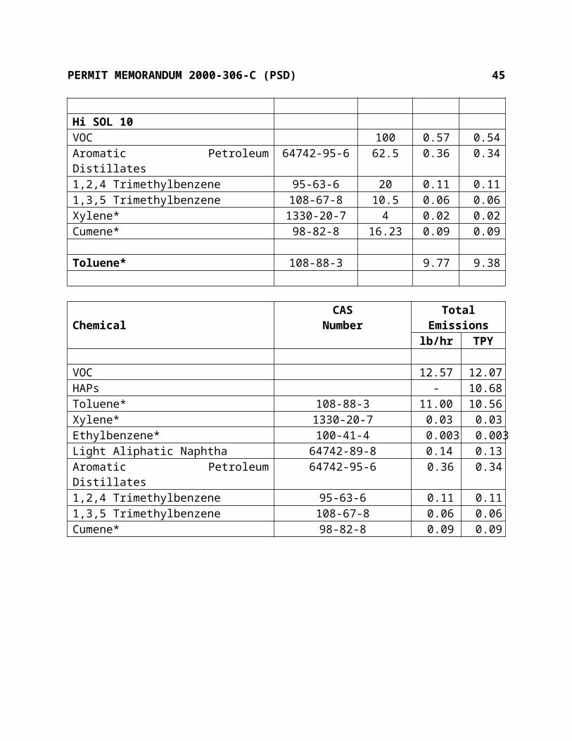
PERMIT MEMORANDUM 2000-306-C (PSD) 45
No pre-construction nor post-construction ambient monitoring will be required. The maximum ambient impacts of the source and the monitoring exemption levels are shown below.
Comparison of Modeled Impacts to Monitoring Exemption LevelsMonitoring Exemption Levels Ambient Impacts
Pollutant Averaging Time ug/m3 ug/m3
NO2 annual 14 6.93PM10 24-hour 10 6.02CO 8-hour 575 209b) Ozone (VOC) Impacts
ODEQ has recently received several gas-fired electrical generating unit permit applications. As a result, ODEQ required this group of sources to conduct an extensive review of their potential impacts using the photochemical model, CAMx. The study was done to assess the ozone impacts in Oklahoma due to proposed new electrical generating units (EGUs) in the region.
CAMx was run for a 1995 base case emissions scenario and the model-estimated ozone concentrations were compared with the observed values of a June 1995 ozone episode. EPA has developed a set of model performance goals for ozone to aid in determining that the model is working adequately. The CAMx model performance statistics for all days of the June 1995 episode meet EPA’s model performance goals by a wide margin (usually by over a factor of 2). Additional analysis of the spatial distribution of the predicted and observed 1-hour and 8-hour ozone concentrations revealed that the model exhibited a fairly good job of estimating the spatial patterns of the observed ozone concentrations. CAMx was then applied using the Oklahoma 32, 16, and 4 kilometer grids and the June 18-22, 1995, episode for two future year emission scenarios:
2007 CAA Base Case: Emissions in 2007 assuming growth and all Clean Air Act Amendment (CAA) mandated controls.
2007 Thirteen New OK Sources: 2007 CAA Base Case including emissions from the original eleven power plants as well as the KM Power Corporation plus the proposed Quad/Graphics facility.
The year 2007 was selected for the future-year assessment because growth and control factors were readily available from the Ozone Transport Assessment Group (OTAG) and Dallas-Fort Worth ozone control plan development modeling domain. The combined NOx and VOC emissions from the 13 New Oklahoma sources are 43.24 and 9.98 tons per day, respectively. The resulting spatial maps of estimated daily maximum 1-hour ozone concentrations for the 2007 Base Case and 2007 thirteen new Oklahoma sources emission scenarios in the Tulsa-Oklahoma City areas are almost identical and are always below the 1-hour ozone standard throughout Oklahoma. Thus, the thirteen new Oklahoma sources do not appear to have any measurable effect on the 1-hour ozone attainment in Oklahoma.

PERMIT MEMORANDUM 2000-306-C (PSD) 46
Since the new Oklahoma sources are estimated to produce changes in peak 8-hour ozone concentrations that are much less than 1 ppb (0.0 ppb to 0.4 ppb), then they are estimated to have no measurable effect on peak 8-hour ozone concentrations in the Tulsa and Oklahoma City areas.
3) ADDITIONAL IMPACTS ANALYSIS
a) Growth Impacts
Construction of the proposed facility will generate approximately 300 temporary jobs. These temporary jobs will last approximately 4 to 5 months. Operation of the facility will generate approximately 1,900 new, permanent jobs. These positions are likely to be filled primarily by residents already residing or working in the Oklahoma City area. The Oklahoma Employment Security Commission reports an unemployment rate of 2.7% in 1999 for Oklahoma County. This amounts to an available unemployed labor force of approximately 9,000. Since an available labor force exists in Oklahoma County, it is unlikely that the facility will contribute to the population growth in the Oklahoma City area. In addition, the construction of the facility is not expected to generate additional commercial growth since the facility will be located in a large previously developed commercial area.
b) Soils and Vegetation
Emissions of VOC, PM10, NOx, and CO from the proposed facility were found to exceed the PSD significance thresholds. This section considers potential impacts to soil and vegetation resulting from these emissions. Based on the preliminary air quality analysis, impacts from CO are below the significance level for ambient air impacts. Since the predicted impacts from CO are insignificant, and atmospheric deposition of CO is not known to have detrimental effects on soils, CO emissions are not anticipated to have any impacts. Based on the full impact air quality analysis, which included other existing sources within the region that may interact with the emissions from the Quad/Graphics facility, impacts from PM10 and NOx were found to meet all primary and secondary National Ambient Air Quality Standards (NAAQS). The EPA set the primary NAAQS in order to protect public health, including the health of "sensitive" populations such as asthmatics, children, and the elderly. The secondary standards set limits to protect public welfare, including protection against decreased visibility, damage to animals, crops, vegetation, and buildings. Since the emissions from PM10 and NOx meet the NAAQS, these emissions are not anticipated to have any adverse effects on local soils or vegetation.
c) Visibility Impairment

PERMIT MEMORANDUM 2000-306-C (PSD) 47
The project is not expected to produce any perceptible visibility impacts in the vicinity of the plant. EPA computer software for visibility impacts analyses, intended to predict distant impacts, terminates prematurely when attempts are made to determine close-in impacts. It is concluded that there will be minimal impairment of visibility resulting from the facility's emissions. Given the limitation of 20% opacity of emissions, and a reasonable expectation that normal operation will result in 0% opacity, no local visibility impairment is anticipated.
4) CLASS I AREA IMPACT ANALYSIS
Based on conversation with the Federal Land Management, due to the distance of the source to any Class I Area, the closest being the Wichita Mountain Wildlife Refuge at approximately 142 km (88 miles), no impacts are anticipated and precludes the requirement to do any formal demonstration.
SECTION VI. OKLAHOMA AIR POLLUTION CONTROL RULES
OAC 252:100-1 (General Provisions) [Applicable]Subchapter 1 includes definitions but there are no regulatory requirements.
OAC 252:100-3 (Air Quality Standards and Increments) [Applicable]Subchapter 3 enumerates the primary and secondary ambient air quality standards and the significant deterioration increments. The primary standards are enumerated in Appendix E and the secondary standards are enumerated in Appendix F of the Air Pollution Control Rules (OAC 252:100). National Ambient Air Quality Standards (NAAQS) are established by the U.S. EPA. The actual ambient air concentration of criteria pollutants are monitored within the state of Oklahoma by ODEQ’s Air Quality Division. At this time, all of Oklahoma is in "attainment" of these standards. In addition, the facility was required to model proposed emissions to demonstrate that the facility would not have a significant impact on ambient air quality standards.
OAC 252:100-5 (Registration, Emission Inventory, and Annual Fees) [Applicable]The owner or operator of any facility that is a source of air emissions shall submit a complete emission inventory annually on forms obtained from the Air Quality Division. Since this is construction for a new facility, no emission inventories or fees have previously been paid.
OAC 252:100-7 (Permits for Minor Sources) [Not Applicable]Subchapter 7 sets forth the permit application fees and the basic substantive requirements for permits for minor facilities. The proposed facility will be a major source subject to Subchapter 8 permitting.

PERMIT MEMORANDUM 2000-306-C (PSD) 48
OAC 252:100-8 (Permits for Part 70 Sources) [Applicable]Part 5 includes the general administrative requirements for part 70 permits. Any planned changes in the operation of the facility which result in emissions not authorized in the permit and which exceed the “Insignificant Activities” or “Trivial Activities” thresholds require prior notification to AQD and may require a permit modification. Insignificant activities mean individual emission units that either are on the list in Appendix I (OAC 252:100) or whose actual calendar year emissions do not exceed the following limits:
5 TPY of any one criteria pollutant 2 TPY of any one hazardous air pollutant (HAP) or 5 TPY of multiple HAPs or 20%
of any threshold less than 10 TPY for single HAP that the EPA may establish by rule
0.6 TPY of any one Category A toxic substance 1.2 TPY of any one Category B toxic substance 6.0 TPY of any one Category C toxic substance
Emissions limitations have been established for each emission unit.
OAC 252:100-9 (Excess Emission Reporting Requirements) [Applicable]In the event of any release which results in excess emissions, the owner or operator of such facility shall notify the Air Quality Division as soon as practical during normal office hours and no later than 4:30 pm the next working day following the malfunction or release. Within ten (10) business days further notice shall be tendered in writing containing specific details of the incident. Part 70 sources must report any exceedance that poses an imminent and substantial danger to public health, safety, or the environment as soon as is practical; but under no circumstances shall notification be more than 24 hours after the exceedance.
OAC 252:100-13 (Open Burning) [Applicable]Open burning of refuse and other combustible material is prohibited except as authorized in the specific examples and under the conditions listed in this subchapter.
OAC 252:100-19 (Particulate Matter) [Applicable] This subchapter specifies particulate matter (PM) emissions limitations of 0.60 lb/MMBTU and 0.41 lb/MMBTU from new and existing fuel-burning equipment with rated heat inputs of 10
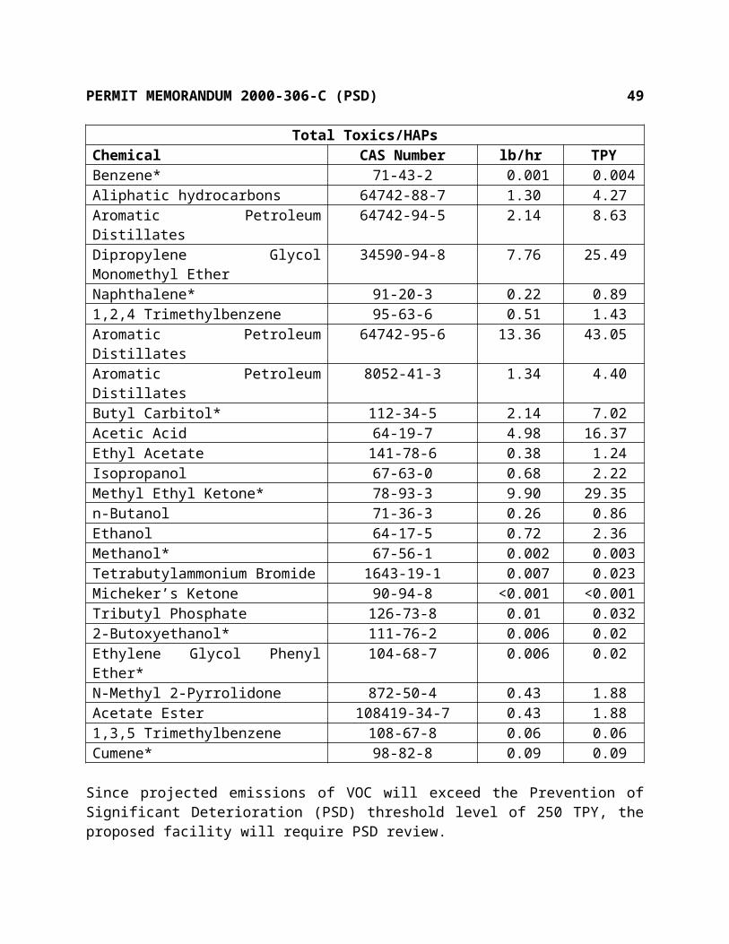
PERMIT MEMORANDUM 2000-306-C (PSD) 49
MMBTUH or less and 62.77 MMBTUH, respectively. The Offset Press dryers/oxidizers will be required to burn only commercial natural gas or propane. AP-42 (7/98), Table 1.4-2 lists PM emissions for natural gas to be 7.6 lb/MMcf or about 0.0076 lb/MMBTU. AP-42 (10/96), Table 1.5-1 lists emissions for propane to be 0.0004 lb/gal which is equivalent to about 0.0044 lb/MMBTU. Manufacturer’s data lists PM emissions for natural gas to be about 0.01 lb/MMBTU.
This subchapter also limits PM emissions from industrial processes. There are no significant particulate emissions from any activity at this facility.OAC 252:100-25 (Visible Emissions and Particulates) [Applicable]No discharge of greater than 20% opacity is allowed except for short-term occurrences which consist of not more than one six-minute period in any consecutive 60 minutes, not to exceed three such periods in any consecutive 24 hours. In no case shall the average of any six-minute period exceed 60% opacity. All fuel-burning equipment on-site will use commercial natural gas or propane. Therefore, it is not necessary to specify any unique procedures to ensure compliance.
OAC 252:100-29 (Fugitive Dust) [Applicable]No person shall cause or permit the discharge of any visible fugitive dust emissions beyond the property line on which the emissions originate in such a manner as to damage or to interfere with the use of adjacent properties, or cause air quality standards to be exceeded, or interfere with the maintenance of air quality standards. Under normal operating conditions, this facility will not cause a problem in this area, therefore it is not necessary to require specific precautions to be taken.
OAC 252:100-31 (Sulfur Compounds) [Applicable]Part 5 limits sulfur dioxide emissions from new equipment (constructed after July 1, 1972). For gaseous fuels the limit is 0.2 lb/MMBTU heat input, maximum three-hour average. The fuel-burning equipment is limited to commercial natural gas or propane. AP-42, Table 1.4-2 (3/98), lists SO2 emissions for natural gas to be 0.0006 lb/MMBTU. At a maximum of 123 ppm sulfur in propane, the maximum emissions will be 0.0156 lb/MMBTU. Thus, the fuel-burning equipment will be in compliance.
OAC 252:100-33 (Nitrogen Oxides) [Applicable]This subchapter limits nitrogen oxides calculated as nitrogen dioxide from any new gas-fired fuel-burning equipment with a rated heat input of 50 MMBTU or greater to a two-hour maximum of 0.20 lb/MMBTU. The maximum one-hour emission rates for the boilers occurs when burning propane, 0.15 lb/MMBTU, which is in compliance.
OAC 252:100-35 (Carbon Monoxide) [Not Applicable]This facility has none of the affected sources: grey iron cupola, blast furnace, basic oxygen furnace, petroleum catalytic cracking unit, or petroleum catalytic reforming unit.
OAC 252:100-37 (Volatile Organic Compounds) [Applicable]

PERMIT MEMORANDUM 2000-306-C (PSD) 50
Part 3 requires VOC storage tanks with a capacity of 400 gallons or more to be equipped with a permanent submerged fill pipe or with a vapor recovery system. All tanks are either ducted to a control device, pressurized, or store a product with a vapor pressure below 1.5 psia, except for the gasoline tank which will be subject to this requirement.Part 5 limits the VOC content of coatings used in coating lines or operations. The coatings to be used are not among the listed types.Part 7 requires fuel-burning and refuse-burning equipment to be operated and maintained so as to minimize emissions. Temperature and available air must be sufficient to provide essentially complete combustion. Combustion control is a BACT requirement to minimize emissions.
Part 7 requires all effluent water separator openings, which receive water containing more than 200 gallons per day of any VOC, to be sealed or the separator to be equipped with an external floating roof or a fixed roof with an internal floating roof or a vapor recovery system. No effluent water separators are located at this facility.Part 7 also requires all reciprocating pumps and compressors handling VOCs to be equipped with packing glands that are properly installed and maintained in good working order and rotating pumps and compressors handling VOCs to be equipped with mechanical seals. The equipment at this location is subject to this requirement.
OAC 252:100-39 (Emission of VOCs in Former Nonattainment Areas) [Applicable]Part 7, Requirements for Specific Operations -39-41 Storage, loading, and transport/delivery of VOCs. Per OAC 252:100-39-4, the facility is exempt from these requirements based on the inks and solvents having actual vapor pressures below 1.5 psia.-39-43 (b) This section applies only to packaging rotogravure, publication rotogravure, and flexographic printing facilities whose potential emissions of VOC are equal to or more than 100 tons/yr. Emissions from this facility will exceed this level.-39-43 (c) (1) An owner or operator of a facility subject to this section which uses VOC containing ink shall ensure that one of the following conditions is met; (A) the volatile fraction of ink, as it is applied to the substrate, contains 25.0 percent by volume or less and 75.0 percent by volume or more of water, (B) the ink as it is applied to the substrate, less water, contains 60.0 percent by volume or more nonvolatile material, (C) the owner or operator installs and operates, a carbon adsorption system that reduces the VOC emissions from the capture system by at least 90.0 percent by weight, or an incineration system that oxidizes at least 90.0 percent of the VOC measured as total combustible carbon to carbon dioxide and water, or an alternative VOC emission reduction system demonstrated to have at least 90.0 percent reduction efficiency, measured across the control system which has been approved by the Division Director. (2) a capture system must be used in conjunction with the emission control systems in –39-43 (c)(1)(C). The design and operation of the capture system must be consistent with good engineering practice, and shall be required to provide for an overall reduction in VOC emissions of at least: (A) 75.0 percent where a publication rotogravure process is employed; (B) 65.0 percent where a packaging rotogravure process is employed; (C) 60.0 percent where a flexographic printing process is employed.

PERMIT MEMORANDUM 2000-306-C (PSD) 51
(d) Compliance with this section shall be accomplished by affected facilities by May 23, 1982. (e) Test procedures to determine compliance with this subchapter must be consistent with EPA Reference Method 24 or equivalent ASTM Methods. The facility will comply with these requirements by complying with the proposed BACT standards, 100% collection efficiency and 99% recovery, which are more restrictive.
OAC 252:100-41 (Hazardous and Toxic Air Contaminants) [Applicable State Only]Part 1 contains the purpose of the subchapter and definitions.Part 3 addresses hazardous air contaminants. NESHAP, as found in 40 CFR Part 61, are adopted by reference as they exist on July 1, 2000, with the exception of Subparts B, H, I, K, Q, R, S, T, W and Appendices D and E, all of which address radionuclides. In addition, General Provisions as found in 40 CFR Part 63, Subpart A, and the Maximum Achievable Control Technology (MACT) standards as found in 40 CFR Part 63, Subparts F, G, H, I, L, M, N, O, Q, R, S, T, U, W, X, Y, CC, DD, EE, GG, HH, II, JJ, LL, KK, OO, PP, QQ, RR, SS, TT, UU, VV, WW, YY, CCC, DDD, EEE, GGG, HHH, III, JJJ, LLL, MMM, NNN, OOO, PPP, RRR, TTT, VVV and XXX are adopted by reference as they exist on July 1, 2000. These standards apply to both existing and new sources of hazardous air contaminants. NESHAP are addressed in the “Federal Regulations” section.Part 5 is a state-only requirement governing toxic air contaminants. New sources (constructed after March 9, 1987) emitting any category “A” pollutant above de minimis levels must perform a BACT analysis and, if necessary, install BACT. All sources are required to demonstrate that emissions of any toxic air contaminant that exceeds the de minimis level do not cause or contribute to a violation of the MAAC. No category “A” pollutants were estimated to exceed a de minimis level, however, BACT was required for PSD review. While HAPs from sources subject to a Part 63 NESHAP are exempted from review under this part, the facility conducted a complete review of all toxics to demonstrate compliance with the MAAC for all toxics. Toxics estimated to exceed their respective de minimis level are listed in the following table.
De minimis Levels Emissions
Toxic CAS # Category lb/hr TPY lb/hr TPYHydrocarbon Petroleum Distillate 8042-47-5 B 1.1 1.2 22.54 74.05Hydrocarbon Petroleum Distillate 64742-46-7 B 1.1 1.2 22.54 74.05Toluene 108-88-3 C 5.6 6.0 610.61 1972.84Xylene 1330-20-7 C 5.6 6.0 3.11 10.10Light Aliphatic Naphtha 64742-89-8 C 5.6 6.0 32.25 105.10Aromatic Petroleum Distillates 64742-94-5 B 1.1 1.2 2.14 8.63Dipropylene Glycol Monomethyl Ether
34590-94-8 C 5.6 6.0 7.76 25.49
Aromatic Petroleum Distillates 64742-95-6 B 1.1 1.2 13.36 43.05

PERMIT MEMORANDUM 2000-306-C (PSD) 52
Butyl Carbitol 112-34-5 C 5.6 6.0 2.14 7.02Acetic Acid 64-19-7 C 5.6 6.0 4.98 16.37Methyl Ethyl Ketone 78-93-3 C 5.6 6.0 9.90 29.35Ethanol 64-17-5 B 1.1 1.2 0.72 2.36
Each of the listed toxics was modeled using the EPA Screen3 modeling program. All toxics were modeled as emitted from the respective stacks except as identified. Since almost all of the toluene, xylene, and light aliphatic naphtha is emitted from the adsorber stacks, these emissions were conservatively modeled as being emitted from one of the two six-in-one headers. A worst case analysis was performed and determined to be when two presses were running and being emitted from one stack. All fugitive type emissions were conservatively estimated to be emitted as an area source from the roof vents with a one foot square area and either 30 foot or 27 foot roof height.
Toxic CAS # MAAC Allowed Modeled ConcentrationHydrocarbon Petroleum Distillate 8042-47-5 100 ug/m3 60.4 ug/m3
Hydrocarbon Petroleum Distillate 6742-46-7 2,000 ug/m3 60.4 ug/m3
Toluene 108-88-3 37,668 ug/m3 1,954 ug/m3
Xylene 1330-20-7 43,427 ug/m3 10 ug/m3
Light Aliphatic Naphtha 64742-89-8 40,000 ug/m3 103 ug/m3
Dipropylene Glycol Monomethyl Ether
34590-94-8 60,625 ug/m3 655 ug/m3
Aromatic Petroleum Distillates 64742-95-6 7,000 ug/m3 1,127 ug/m3
Aromatic Petroleum Distillates 64742-94-5 7,000 ug/m3 180 ug/m3
Butyl Carbitol 112-34-5 200 ug/m3 180 ug/m3
Acetic Acid 64-19-7 2,456 ug/m3 420 ug/m3
Methyl Ethyl Ketone 78-93-3 59,000 ug/m3 1,032 ug/m3
Ethanol 64-17-5 38,000 ug/m3 75 ug/m3
OAC 252:100-43 (Sampling and Testing Methods) [Applicable]All required testing must be conducted by methods approved by the Executive Director under the direction of qualified personnel. All required tests shall be made and the results calculated in accordance with test procedures described or referenced in the permit and approved by Air Quality.
OAC 252:100-45 (Monitoring of Emissions) [Applicable]

PERMIT MEMORANDUM 2000-306-C (PSD) 53
Records and reports as Air Quality shall prescribe on air contaminants or fuel shall be recorded, compiled, and submitted as specified in the permit.
SECTION VII. FEDERAL REGULATIONS
PSD, 40 CFR Part 52 [Applicable]The facility will have emissions exceeding the 250 TPY threshold for a criteria pollutant, therefore, it is subject to PSD review. PSD review has been completed in Section IV.
NSPS, 40 CFR Part 60 [Applicable]Subpart Dc, Industrial-Commercial-Institutional Steam Generating Units. This subpart affects steam generating units with a design capacity between 10 and 100 MMBTUH heat input and which commenced construction or modification after June 9, 1989. For gaseous-fueled units, the only applicable standard of Subpart Dc is a requirement to keep records of the fuels used. The 62.77 MMBTUH gas-fired boilers are affected units as defined in the subpart since the heating capacity is above the de minimis level. Recordkeeping will be specified in the permit.
Subpart Kb, Volatile Organic Liquids Storage Vessels. This subpart affects VOL storage vessels (including petroleum liquids storage vessels) for which construction, reconstruction, or modification commenced after July 23, 1984, and which have a capacity of 10,567 gallons (40 cubic meters) or more. Tanks T1, T5-T12, T18, T23, T26-T29, T32-T35 meet the de minimis level for applicability to this subpart.- 40 CFR 60.110(b) specifies that vessels with design capacities less than 19,813 gallons are exempt from the General Provisions. However, compliance with §60.116b (a) and (b) is required. Tank T-18 meets this capacity limit and shall keep records showing the capacity of the vessel for the life of the source.- 40 CFR 60.110(c) specifies that vessels either with a capacity greater than or equal to 40,000 gallons storing a liquid with a maximum true vapor pressure less than 0.51 psi or with a capacity greater than or equal to 19,813 gallons but less than 39,890 gallons storing a liquid with a maximum true vapor pressure less than 2.175 psi are exempt from the General Provisions. However, compliance with §60.116b (a) and (b) is required. Tanks T1, T5-T12, T23, T26-T29 will have capacities between 19,813 and 39,890 gallons and store liquids with maximum vapor pressures below 2.175 psi.- 40 CFR 60.110(d) (2) specifies that this subpart does not apply to pressure vessels designed to operate in excess of 29.73 psi and without emissions to the atmosphere. Tanks T-32 – T-35 are exempt based on being pressurized vessels which will maintain a pressure above 29.73 psi.

PERMIT MEMORANDUM 2000-306-C (PSD) 54
Subpart QQ, Standards of Performance for the Graphics Arts Industry: Publication Rotogravure Printing. This subpart applies to each publication rotogravure printing press that commences construction, modification, or reconstruction after October 28, 1980. The facility is subject to the standards of this subpart which limits the discharge into the atmosphere more than 16 percent of the total mass of VOC solvent and water used at the facility during any one performance averaging period and after the date required for completion of the test. 40 CFR Part 63, Subpart KK is more restrictive and takes precedence.
NESHAP, 40 CFR Part 61 [Not Applicable]There are no emissions of any of the regulated pollutants: arsenic, asbestos, benzene, beryllium, coke oven emissions, radionuclides or vinyl chloride.
NESHAP, 40 CFR Part 63 [Applicable]Subpart B, Requirements for Control Technology determinations for Major Sources in Accordance With Clean Air Act Sections, Sections 112(g) and 112(j). This subpart contains the requirements for control technology determinations for major sources in accordance with Clean Air Act Sections, 112(g) and 112(j). Oklahoma regulations (OAC 252:100-8-4(2)) adopt federal regulations (40 CFR Subpart B, Sections 63.40 to 63.44) by reference. These regulations, Requirements for Control Technology for Major Sources of Hazardous Air Pollutants, implement the provisions of the federal Clean Air Act Amendment Section 112(g).
Since the Ink Jet operation will be a major source of HAPs (defined as the potential to emit 10 or more tons per year of an individual HAP or 25 tons per year of total HAPs) and there is no promulgated or proposed Maximum Achievable Control Technology (MACT) standard for the source category, Ink Jet operations at printing facilities, pursuant to federal Clean Air Act Amendment Section 112(d), are subject to review under Section 112(g) and a case-by-case MACT determination.
A breakdown of the proposed emissions of HAP and Total Toxics is listed below.
ChemicalTotal Emissions
lb/hr TPYVOC 10.95 32.78HAPs - 28.73Non-HAP Toxics 1.24 4.05
The case-by-case MACT Determination
For new sources, the MACT emission limitation will be no less stringent than the emission control that is achieved in practice by the best controlled similar source. The emissions

PERMIT MEMORANDUM 2000-306-C (PSD) 55
reduction must achieve a maximum degree of HAP emission reduction with consideration to the cost of achieving such emission reductions, the non-air quality health and environmental impacts, and energy requirements.
In general for new sources, the MACT emission limitation will be no less stringent than the emission control that is achieved in practice by the best controlled similar source. However, after review of the USEPA RACT/BACT/LAER clearinghouse, South Coast Air Quality Management District, California Air Resource Board, Texas Natural Resource Conservation Commission and the San Joaquin Valley Air Pollution Control District to determine whether BACT technology exists for ink jet print operation Volatile Organic Compound (VOC) emissions, no BACT determinations were found for ink jet printing. One LAER determination was found in the state of Illinois (IL-0055) that utilized pollution prevention in the form of limiting vapor pressure in solvent. This was also confirmed through conversations with EPA Headquarters contacts.
Since a base level of control was not derived from existing source review, the control requirement will be based on a “top-down” analysis for the proposed ink jet print operations using the following steps:
- Identification of all control technologies- Elimination of technically infeasible options- Rank remaining control technologies by control effectiveness- Evaluation of the most effective controls and document results- Selection of MACT
Available control technologies
The following discusses the alternative control techniques and devices available for VOC sources and application of these alternative control technologies. As required by the “top-down” format, they are discussed, evaluated and presented in order of decreasing control effectiveness, with the most stringent control technique discussed first. Two methods of hydrocarbon emission control, carbon adsorption and incineration, theoretically are possible. However, adsorption has been tried, but the collection of MEK reacts on activated carbon to oxidize and possibly form hot spots that could lead to bed fires. MEK breaks down on carbon to form acidic by-products making it necessary to construct the adsorbers out of stainless steel. MEK is substantially miscible with water (27% MEK in water and 12% water in MEK) that does not allow for a clean decantation. The distilled MEK that is recovered would contain approximately 15% water deeming it as unusable and thus having to be sent off for proper waste disposal. Thus, adsorption is expensive and inefficient, and will not be explored for this project.
Thermal oxidizers are a traditional method for controlling VOC emissions. Thermal oxidizers offer a great deal of flexibility and are capable of handling a wide range of flow characteristics. There are three types of thermal oxidizers that are used for VOC control: recuperative, regenerative and catalytic.

PERMIT MEMORANDUM 2000-306-C (PSD) 56
Recuperative thermal oxidizers are conventional thermal oxidizers that utilize an air-to-air heat exchanger for fume pre-heat. For vent streams with VOC concentrations ranging between 25 and 50% of the lower explosive limit (LEL) recuperative thermal oxidizers are generally used. Typically these units operate at a combustion chamber temperature ranging from 1,400 - 1,800 o
F depending on the organic compounds and regulatory requirements. While this type of unit is very flexible, and offers the greatest destruction efficiency (95 -99+%), the major disadvantage is the auxiliary fuel usage required to maintain combustion temperatures.
Regenerative thermal oxidizers incorporate high temperature combustion along with very high-energy efficiency through the use of large chambers filled with ceramic heat exchanger media. These systems are capable of up to 95% energy efficiency, compared to a maximum energy efficiency of 70% using a conventional shell-and-tube or plastic type metallic heat exchanger. Regenerative units are suited for high flow rate, low concentration fume streams (<10% of the LEL) typically less that 1500 ppm. The disadvantage is they are large, more complex, and more expensive than recuperative or catalytic designs. They are rarely used on fume streams of less than 10,000 scfm. Destruction efficiency is limited to 95%.
The third oxidizer type is catalytic oxidizers. This system increases the rate of the oxidation reaction allowing the unit to operate at lower temperatures than conventional thermal oxidizers. Typically a catalyst is constructed of a ceramic or metallic substrate having a high surface area per unit volume. A thin layer of a catalyst (typically a noble metal such as platinum or palladium) is applied to the substrate. Catalytic units generally operate with VOC streams in the 10 to 20% LEL range. To operate efficiently, catalytic units require the fumes to be pre-heated to approximately 600o F. This is done with either a heat exchanger or an auxiliary fuel burner. Depending on the VOC content of the fume stream the temperature at the exit of the catalyst may be 1000o F or more. Typically catalyst substrates are limited to temperatures of less than 1,200o F, which limit the catalytic unit’s ability to handle high VOC concentrations. Catalytic units offer destruction efficiencies in the 90 to 95% range. As the catalyst begins to degrade over time and leaks develop in bed supports, the destruction efficiency declines.
In addition, the use of any type of oxidizer would require a system to capture the emissions from each ink jet unit. The proposed facility will contain about two hundred ink jet units. PTE’s, enclosures that completely surround a source of fugitive emissions such that all volatile organic compound (VOC) emissions are contained and directed to a control device, are reviewed in combination with the control devices.
The emissions reduction must achieve a maximum degree of HAP emission reduction with consideration to the cost of achieving such emission reductions, the non-air quality health and
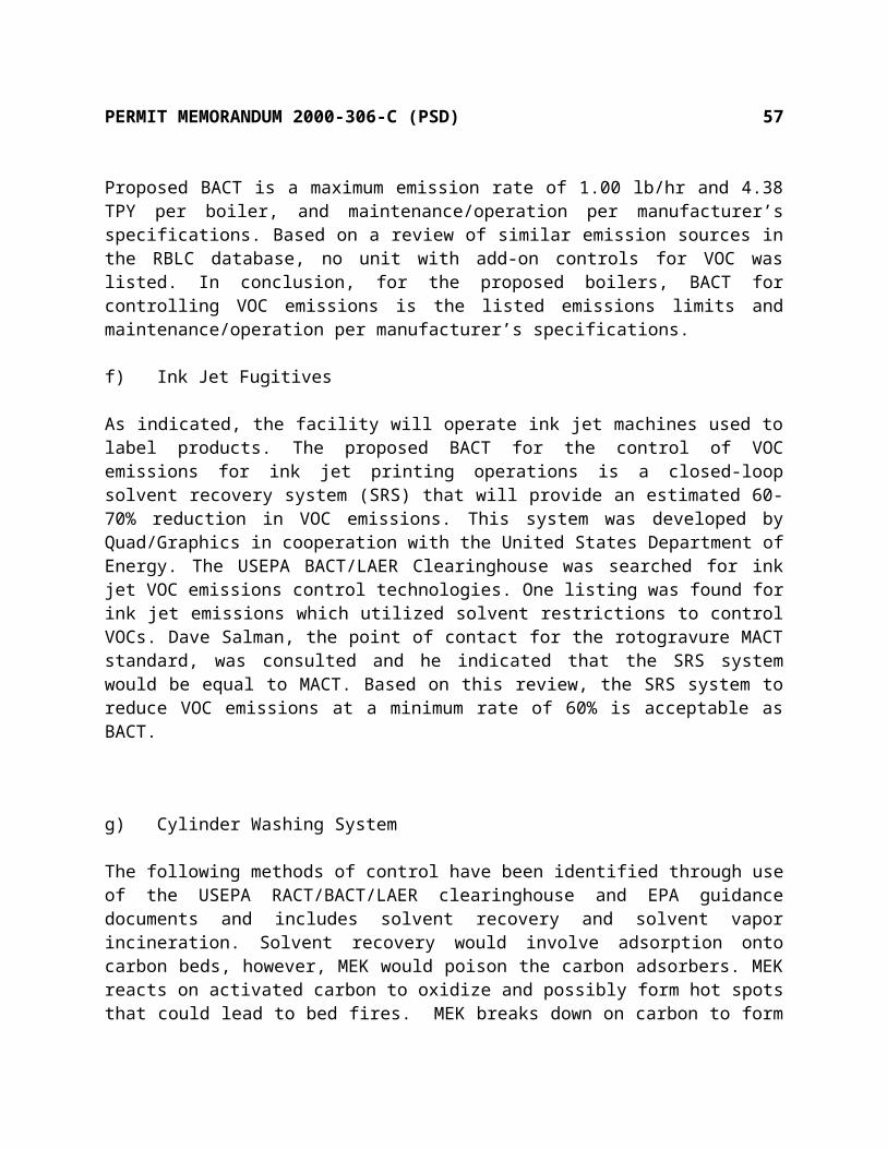
PERMIT MEMORANDUM 2000-306-C (PSD) 57
environmental impacts, and energy requirements. The following are the costs associated with the identified control equipment.
Control AlternativeControl
EffectivenessUncontrolled
EmissionsEmissions Reductio
n
Annualized Cost ($/year)
Cost Effectiveness($/ton)
PTE &Thermal Oxidizer
97.5% 54.64 53.27 $493,466 $9,264
PTE &Catalytic Oxidizer
95% 54.64 51.90 $1,046,092 $20,155
PTE &Carbon Adsorption
95% 54.64 51.90 $3,109,427 $24,029
Solvent Recovery System
60% 54.64 21.85 $80,225 $3,672
Based on the alternatives explored, the most efficient and economical control technology chosen by Quad/Graphics for the ink jet operations is the SRS which is acceptable as the case-by-case MACT. The additional control alternatives have been determined to be cost prohibitive. Since the SRS system has been chosen as the control method, the benefits associated with the recovery of the solvent have not been included.
Subpart N, National Emission Standards for Chromium Emissions From Hard and Decorative Chromium Electroplating and Chromium Anodizing Tanks. This subpart applies to each chromium electroplating or chromium anodizing tank at facilities performing hard chromium electroplating, decorative chromium electroplating, or chromium anodizing. The facility will conduct hard chromium electroplating, therefore, it is subject to this subpart. This subpart will require the facility’s hard chromium tanks to meet an emission rate of 0.015 mg/dscm of ventilation air. The testing, recordkeeping, and reporting of this subpart will be a requirement of the permit.

PERMIT MEMORANDUM 2000-306-C (PSD) 58
Subpart KK, Standards for Hazardous Air Pollutant Emissions from the Printing and Publishing Industry. This subpart applies to each new and existing facility that is a major or area source of hazardous air pollutants at which publication rotogravure, product and packaging rotogravure, or wide-web flexographic printing presses are operated. The facility will contain publication rotogravure presses which will emit HAPs above major source levels, therefore, the facility will be subject to this subpart. The affected sources include all the rotogravure presses and all affiliated equipment, including proof presses, cylinder and parts cleaning, ink and solvent mixing and storage equipment, and solvent recovery equipment at a facility. This subpart requires each rotogravure affected source to limit emissions of organic HAP to no more than eight percent of the total volatile matter used each month. The emission limitation may be achieved by overall control of at least 92 percent of organic HAP used, by substitution of non-HAP materials for organic HAP, or by a combination of capture and control technologies and substitution of materials. Quad/Graphics will comply with this standard by use of the solvent recovery system and will demonstrate compliance monthly by use of a liquid-liquid material balance as allowed and described in §63.824(b)(1)(i). The testing, monitoring, recordkeeping, and reporting of this subpart will be a requirement of the permit.
CAM, 40 CFR Part 64 [Not Applicable At This Time]Compliance Assurance Monitoring (CAM) as published in the Federal Register on October 22, 1997, applies to any pollutant specific emission unit at a major source, that is required to obtain a Title V permit, if it meets all of the following criteria:
It is subject to an emission limit or standard for an applicable regulated air pollutant It uses a control device to achieve compliance with the applicable emission limit or standard It has potential emissions, prior to the control device, of the applicable regulated air
pollutant of 100 TPY
The thermal oxidizers are subject to this part, however, they are not large emissions units and shall submit the information required under §64.4 as part of the application for a renewal of a Part 70 permit. The adsorbers are part of the rotogravure printing press which is subject to an emission limit under NESHAP, Subpart KK. Emission units subject to an emission limit or standard proposed after November 15, 1990, pursuant to Section 111 or 112 of the Clean Air Act are exempt from CAM. Therefore, the carbon adsorbers are exempt from CAM.
Chemical Accident Prevention Provisions, 40 CFR Part 68 [Applicable]The facility stores inks, solvents, and fuel on-site. This facility will have two 30,000 gallon and two 60,000 gallon pressurized tanks that store propane. Propane is a regulated substance and it will be present in more than the applicable threshold of 10,000 lbs. However, facilities using flammable substances as a fuel are not subject to the requirements of this part. The facility stores propane for use as an emergency fuel and is exempt from the Chemical Accidental Prevention Provisions. More information on this federal program is available at the web site: http://www.epa.gov/ceppo/.

PERMIT MEMORANDUM 2000-306-C (PSD) 59
Stratospheric Ozone Protection, 40 CFR Part 82 [Applicable]This facility does not produce, consume, recycle, import, or export any controlled substances or controlled products as defined in this part, nor does this facility perform service on motor (fleet) vehicles which involves ozone-depleting substances. Therefore, this facility is not subject to these requirements. To the extent that the facility will have air-conditioning units that apply, the permit requires compliance with Part 82.
VIII. COMPLIANCE
Tier Classification And Public ReviewThe applicant published the “Notice of Filing a Tier III Application” in The Daily Oklahoman on February 21, 2001. The notice stated that the application was available for public review at the Department of Environmental Quality, Air Quality Division. The applicant published the “Notice of Draft Permit” in The Daily Oklahoman on June 18, 2001. The notice stated that the draft permit, Notice of MACT Approval, and application were available for public review at the Department of Environmental Quality, Air Quality Division and that a public meeting would be held on July 18, 2001, at the South Oklahoma City Chamber of Commerce. The public meeting was held as planned. No comments were received from the public or EPA, however, several comments were received from the permittee and are listed following. The applicant published the “Notice of Proposed Permit” in The Daily Oklahoman on July 27, 2001. The notice stated that the proposed permit, Notice of MACT Approval, and application were available for public review at the Department of Environmental Quality, Air Quality Division. No comments were received from the public or EPA. The draft and proposed permit were also made available for public review on the Air Quality section of the DEQ Web page: http://www.deq.state.ok.us/. This facility is not located within 50 miles of the Oklahoma border with another state.
As indicated, the permittee had several comments concerning the draft permit. Most of these comments were minor wording changes and are not described here. However, three of these comments require clarificatrion here. However, none of the changes made are significant and have been included in the proposed permit.
1) Comment
The permittee has proposed that an addition to the Specific Conditions to indicate that ODEQ will work with the facility to provide all off-set credits allowed under existing or new regulations should ODEQ modify its state implementation plan due to non-attainment status.
Reply
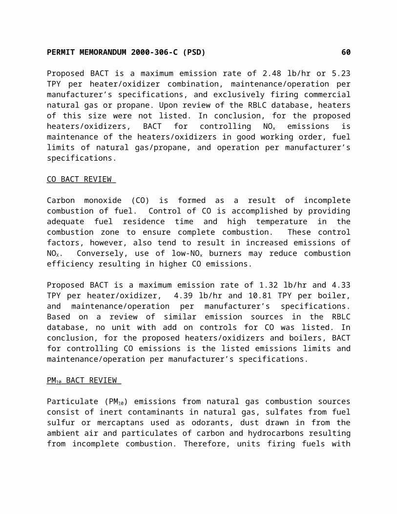
PERMIT MEMORANDUM 2000-306-C (PSD) 60
Added a Specific Condition to indicate that ODEQ will work with the facility to provide any allowable off-set credits.
2) Comment
The permittee has proposed that an addition to the Standard Conditions be made to indicate that, due to the size and scope of the project, extensions of the construction permit is anticipated.
Reply
Since the Standard Conditions are not specific to a facility changes are not made to these conditions. However, extensions of construction permits are allowed under OAC 252:100-8-1.4 (b) as indicated in the Standard Conditions. Therefore, a Specific Condition to indicate that the permittee is anticipating the need for such has been added.
3) Comment
The permittee has proposed that an addition to the Standard Conditions be made to Section VIII, Paragraph C to indicate that “if the permittee is in compliance with the terms of the permit and other regulatory requirements, it shall be considered to be acting in accordance with such air requirements.”
Reply
After further review of this condition, the permittee has determined that no clarification of this condition is needed. Therefore, no change has been made.
The permittee has submitted an affidavit that they are not seeking a permit for land use or for any operation upon land owned by others without their knowledge. The affidavit certifies that the applicant has a contract which is given to accomplish the permitted purpose and that the landowner has been notified.
Fees PaidConstruction permit fee of $2,000.
VIII. SUMMARY
The applicant has demonstrated the ability to comply with all applicable requirements. Ambient air quality standards are not threatened at this site. There are no active Air Quality compliance or enforcement issues concerning this facility. Issuance of the permit is recommended.

PERMIT TO CONSTRUCTAIR POLLUTION CONTROL FACILITY
SPECIFIC CONDITIONS
Quad/Graphics, Inc.Oklahoma City Facility Permit Number 2000-306-C (PSD)
The permittee is authorized to construct in conformity with the specifications submitted to Air Quality on December 19, 2000. The Evaluation Memorandum, dated August 17, 2001, is attached to this permit to explain the derivation of applicable permit requirements and estimates of emissions; however, it does not contain operating limitations or permit requirements. Commencing construction or operations under this permit constitutes acceptance of, and consent to, the conditions contained herein:
1. Points of emissions, emissions limitations, and requirements for each point: [OAC 252:100-8-6(a)]
A) The permittee shall be authorized to construct 12 Offset Presses with the following re-quirements and limits.
VOC Emissions and Usage Limits for 12 Offset Presses
ProductMaximum VOC Content by Wt. Maximum Usages
Emissionslb/hr TPY
Heatset Inks lb/hr lb/yrVOC 44% 2,411 15,840,000 22.54 74.05Auto Blanket Wash gal/hr gal/yrVOC 30% 1.95 12,780 2.61 8.54Manual Blanket Wash gal/hr gal/yrVOC 100% 3.77 24,780 14.89 48.92Fountain Solution gal/hr gal/yrVOC 24% 11.51 75,600 14.66 48.15Miscellaneous Solvent gal/hr gal/yrVOC 100% 0.58 3,780 2.24 7.29
Combustion Emissions per Offset Press (16 MMBTUH)NOx CO VOC PM10 SO
lb/hr TPY lb/hr TPY lb/hr TPY lb/hr TPY lb/hr TPY2.48 5.23 1.32 4.33 0.09 0.28 0.12 0.39 0.25 0.05

i) Emissions from each Offset dryer shall be exhausted through an oxidizer with a minimum destruction efficiency of 97.5%. [OAC 252:100-8-6(a)]
ii) The Offset dryers shall be authorized to burn pipeline-grade natural gas or propane. Propane usage shall be limited to 2,121.60 gallons/hr for 12 presses and 356,428.80 gallons per year for 12 presses. Propane sulfur content shall be limited to a maximum of 123 ppm by weight. [OAC 252:100-31]
iii) Each dryer shall be operated under a ½ inch negative water column pressure and there are no visible emissions directly attributable to the press or dryer. Based on meeting these requirements each dryer will be considered to have 100% capture efficiency.
[OAC 252:100-8-6(a)]
iv) Compliance with the hourly usage rate limits and hourly emission limits shall be determined monthly and based on the total monthly usage divided by the total hours of operation of the twelve presses. Compliance with the annual usage rate limits and annual emissions limits shall be determined monthly and based on 12-month rolling totals.
[OAC 252:100-8-6(a)]
v) All emission calculations shall be based on the highest concentrations as listed on the respective MSD sheets, usage rates as calculated according to (iv) and using the following factors: [OAC 252:100-8-6(a)]
a) Heatset inks – 100% capture efficiency and 97.5% destructionb) Automatic Blanket Wash – 40% capture with 97.5% destruction and 60% emitted as
uncontrolled fugitivec) Manual Blanket Wash – 40% retained (not emitted) and 60% emitted as uncontrolled
fugitivesd) Fountain Solution – 40% capture with 97.5% destruction and 60% emitted as
uncontrolled fugitivee) Miscellaneous Solvents – 40% retained (not emitted) and 60% emitted as uncontrolled
fugitives
vi) Compliance with the emission limits for the dryers shall be based on compliance with the fuel-burning limitations and an annual statement from the propane supplier demonstrating 123 ppm by weight sulfur or less . [OAC 252:100-8-6(a)]

vii) Within 60 days of operation of each oxidizer, not to exceed 180 days from initial start-up, and on each 5 year anniversary of the issuance of the operating permit, the permittee shall conduct performance testing and furnish a written report to Air Quality documenting compliance with the minimum 97.5% destruction efficiency. Performance testing by the permittee shall use one of the following test methods specified in 40 CFR 60:
[OAC 252:100-8-6(a)]
Method 18: Measurement of Gaseous Organic Compound Emissions by Gas Chromatography.Method 25: Determination of Non-Methane Organic Emissions from Stationary Sources.
viii) With the operating permit application, the permittee shall submit the method to be used to document the required temperature of the thermal oxidizers as determined by compliance testing. The permittee shall also submit the method to be used to monitor the flow of air into each dryer. [OAC 252:100-8-6(a)]
B) The permittee shall be authorized to construct 12 Rotogravure Presses with the following requirements and limits.
ChemicalCAS
NumberTotal Emissionslb/hr TPY
VOC 630.56 2071.40HAPs - 1970.79Toluene 108-88-3 596.32 1958.89Xylene 1330-20-7 2.80 9.19Ethylbenzene 100-41-4 0.82 2.71Light Aliphatic Naphtha 64742-89-8 30.56 100.39
ProductMaximum %
ContentMaximum Usage Emissions
gal/hr gal/yr lb/hr TPYYellow 939.12 6,170,016VOC 61.67 238.61 783.84Red 547.68 3,598,260VOC 53 119.59 392.86Blue 547.92 3,599,832VOC 55.97 126.35 415.05Black 665.16 4,370,100VOC 51.05 146.01 479.65

i) Solvent laden air from each Rotogravure Press shall be exhausted through a carbon adsorber with a minimum control efficiency of 98%. During regeneration of the carbon adsorbers, the VOC/HAPs stream shall be exhausted to a condenser unit for recovery of VOCs/HAPs. [OAC 252:100-8-6(a)]
ii) Each Rotogravure Press shall be contained within a permanent total enclosure* (PTE) which will be considered to have 100% capture efficiency. [OAC 252:100-8-6(a)]
a) The total area of all natural draft openings (NDOs) shall not exceed five percent of the surface area of the enclosure’s four walls, floor, and ceiling. (An NDO is defined as an opening that is not connected to a duct in which a fan or a blower is installed.)
b) The average face velocity (FV) of air through all NDOs shall be at least 3,600 m/hr (200 ft/min), which equates to a pressure drop of 0.004 inches of water. The direction of air through all NDOs shall be into the enclosure.
c) Any NDO shall be at least four equivalent opening diameters from any VOC emitting source. The equivalent diameter of an opening is four times the opening area divided by the perimeter.
d) All access doors and windows which are not included in the calculations for NDOs shall be closed during routine operation.
e) Any exhaust point from the enclosure shall be at least four equivalent duct or hood diameters from each NDO.f) All VOC emissions must be captured and contained for discharge through a control device.* may be individual, individual pressroom or entire pressroom
iii) Compliance with the hourly usage rate limits and hourly emission limits shall be determined monthly and based on the total monthly usage divided by the total hours of operation of the twelve presses. Compliance with the annual usage rate limits and annual emissions limits shall be determined monthly and based on 12-month rolling totals.
[OAC 252:100-8-6(a)]
iv) All emission calculations shall be based on the highest concentrations as listed on the respective MSD sheets, usage rates as calculated according to (iii), and 95% overall system efficiency.
During the first six (6) months of operation of each new press the overall VOC control efficiency of each press shall be at least 92% averaged over any three (3) consecutive months and a monthly overall average VOC control efficiency of greater than 90%.
[OAC 252:100-8-6(a)]
v) The Rotogravure Presses are subject to 40 CFR 63, Subpart KK, and shall comply with

all applicable parts including testing, monitoring, and reporting. The requirements of this subpart are detailed in S.C. 3. [40 CFR 63 Subpart KK]
C) The permittee shall be authorized to construct the following storage tanks with the listed requirements and limits.
HAPs VOCsSource TPY lb/hr TPYTanks, T-01 – T-12 0.098 0.023 0.098Tanks, T-13 – T-17 0.009 0.005 0.009Tanks, T-18 – T-36 0.15 0.035 0.15Tanks, T-37 – T-38 - 0.002 0.006Tanks, T-43 – T-44 - 0.381 1.68
Tank Number
Material Size, gallons Throughput, gallons
T-01 Yellow Rotogravure Ink 20,000 3,702,011T-02 Red Rotogravure Ink 10,000 2,158,955T-03 Blue Rotogravure Ink 10,000 2,159,901T-04 Black Rotogravure Ink 10,000 3,496,081T-05 Coated Rotogravure Extender 20,000 2,115,230T-06 Coated Rotogravure Extender 20,000 2,115,230T-07 Uncoated Rotogravure Extender 20,000 995,402T-08 Uncoated Rotogravure Extender 20,000 995,402T-09 Toluene and Recovered Toluene 30,000 4,644,442T-10 Toluene and Recovered Toluene 30,000 4,644,442T-11 Toluene and Recovered Toluene 30,000 4,644,442T-12 Toluene and Recovered Toluene 30,000 4,644,442T-13 Yellow Rotogravure Ink 10,000 180,233T-14 Red Rotogravure Ink 8,000 93,750T-15 Blue Rotogravure Ink 10,000 187,500T-16 Black Rotogravure Ink 8,000 120,000T-17 Coated Rotogravure Extender 10,000 258,073T-18 Yellow Concentrate (CY1) 12,000 1,295,742T-19 Rubine Red Concentrate (CR1) 10,000 677,334T-20 Barium Lithol Concentrate (CR2) 8,000 420,050T-21 Blue Concentrate (CB1) 10,000 893,039T-22 Black Concentrate (CK1) 10,000 838,836T-23 Clay Concentrate (AC1) 20,000 852,055T-24 Ethyl Cellulose Compound (AEC1) 10,000 777,526T-25 Wax Compound (AW1) 10,000 449,921T-26 Resinate MR560 (R1A) 30,000 3,351,611T-27 Resinate MR522 (R1B) 30,000 3,351,611T-28 Jonrez MR522 (R2) 30,000 809,085

T-29 Jonrez MR522 (R3) 30,000 809,085
Tank Number
Material Size, gallons Throughput, gallons
T-30 Yellow ink mixing 5,000 3,702,011T-31 Red ink mixing 5,000 2,158,955T-32 Blue ink mixing 5,000 2,159,901T-33 Black ink mixing 5,000 3,496,081T-34 Coated extender mixing 5,000 4,230,460T-35 Uncoated extender mixing 5,000 1,990,804T-36 Ethylcellulose 5,000 777,526T-37 Manual Blanket Wash 5,500 49,560T-38 Automatic Blanket Wash 2,500 25,560T-39 Propane 30,000 -T-40 Propane 30,000 -T-41 Propane 60,000 -T-42 Propane 60,000 -T-43 Unleaded Gasoline 5,000 793,875T-44 Diesel Fuel 5,000 793,875
i) Tanks T-1 – T-36 shall be designed so that emissions are processed through a carbon adsorber providing a minimum control efficiency of 98%. [OAC 252:100-8-6(a)]
ii) Tanks T-39 – T-42 shall be maintained at a minimum pressure of 29.73 psi without emissions to the atmosphere. [40 CFR 60 Subpart Kb]
iii) Tank T-43 shall be equipped with a permanent submerged fill pipe or equivalent. [OAC 252:100-41]
iv) Records showing the capacity of Tanks T1, T5-T12, T18, T23, and T26-T29 shall be retained for the life of each of the listed tanks. [40 CFR 60 Subpart Kb]
v) Compliance with the listed emissions limitations shall be based on demonstration of compliance with the tank throughputs. Compliance with the annual throughputs shall be determined monthly and based on 12-month rolling totals. [OAC 252:100-8-6(a)]

D) The facility shall be authorized to construct three Hexavalent hard chromium electroplating tanks with the following requirements and limits.
Chromium VI EmissionsTank lb/hr TPYCT-1 0.00056 0.0015CT-2 0.00056 0.0015CT-3 0.00056 0.0015
i) Each of the electroplating tanks shall be constructed with a wet scrubber which will limit Chromium VI emissions below 0.015 mg/dscm of exhaust air. [40 CFR 63 Subpart N]
ii) Each of the electroplating tanks shall be limited to 5,200 hours of actual plating operations annually. With the operating permit application, the permittee shall submit the method to be used to demonstrate compliance with the hours limitation.
[OAC 252:100-8-6(a)]
iii) Each of the Hard Chromium electroplating tanks are subject to 40 CFR Part 63, Subpart N, and shall comply with applicable requirements including but not limited to the following: [40 CFR 63 Subpart N]
a. §63.342 (c)(1)(i) – total chromium in the exhaust gas stream discharged to the atmosphere shall not exceed 0.015 milligrams per dry standard cubic meter.
b. §63.343 (a)(2) – the facility shall comply with the emission standard upon startup. (b) (1) – the permittee shall perform an initial performance test as required under §63.7, using the procedures and test methods listed in §63.7 and §63.344. (c)(1) – the permittee shall determine the outlet chromium concentration using the test methods and procedures in §63.344 (c), and shall establish as a site-specific operating parameter the pressure drop across the system, setting the value that corresponds to compliance with the applicable emission limitation, using the procedures in §63.344 (d)(5). The permittee may conduct multiple performance tests to establish a range of compliant pressure drop values, or may set as the compliant value the average pressure drop measured over the three test runs of one performance test and accept ±1 inch of water column from this value as the compliant range.
c. §63.344 (a) – the permittee shall conduct a performance test using the methods and procedures in this section and §63.7. (c) – the permittee shall use any of the following test methods to demonstrate compliance with the standard; Method 306 or Method 306A, The California Air Resources Board Method 425, Method 306B, or Alternate test methods according to the procedures of §63.7(f). (d) – the permittee shall follow the procedures of this section to establish site-specific operating parameter values. (e) – the permittee shall follow the procedures of this section for measuring the outlet
chromium concentration from an add-on air pollution control device that is used to control multiple sources.
d. §63.345 (b) – the permittee is subject to and shall comply with the requirements of §63.5(a), (b)(1), (b)(5), (b)(6), and (f)(1). (b)(1) – the permittee shall submit a notification of construction the Administrator which shall contain the required information of this section, as appropriate.
e. §63.346 (a) – the permittee shall fulfill all recordkeeping requirements outlined in this section and in the General Provisions to 40 CFR part 63, according to the applicability of subpart A of this part as identified in Table 1 of this subpart.
f. §63.347 (a) - the permittee shall fulfill all reporting requirements outlined in this section and in the General Provisions to 40 CFR part 63, according to the applicability of subpart A of this part as identified in Table 1 of this subpart. (c)(2)(ii) – a notification of the date when construction or reconstruction was commenced, shall be submitted no later than 30 calendar days after such date. (c)(2)(iii) – a notification of the actual date of startup of the source shall be submitted within 30 calendar days after such date. (d)(1) – the permittee shall notify the Administrator in writing of the intention to conduct a performance test at least 60 calendar days before the test is scheduled to begin to allow the Administrator to have an observer present during the test. (e)(2) – before a title V permit is issued to the owner or operator of an affected source, each time a notification of compliance status is required under this part, the owner or operator shall submit to the Administrator a notification of compliance status, signed by the responsible official, as defined in §63.2, who shall certify its accuracy, attesting to whether the affected source has complied with this subpart. After a title V permit has been issued to the owner or operator, the notification of compliance status shall be submitted to the appropriate permitting authority and include the items per (e)(2)(i) through (e)(2)(ix). (e)(3) – a notice of compliance status shall be submitted to the Administrator no later than 90 calendar days following completion of the compliance demonstration required by §63.7 and §63.343 (b). (f)(2) – reports of performance tests results shall be submitted to the Administrator no later than 90 days following the completion of the performance test, and shall be submitted as part of the notification of compliance status required by paragraph (e)of this section. (g)(1) – the permittee shall submit a summary report to the Administrator to document the ongoing compliance status and shall contain the information identified in (g)(3) of this section, and shall be submitted semiannually except when other frequencies are approved by the Administrator.
E) The facility shall be authorized to construct five 62.77 MMBTUH (1,500 nominal HP) boilers with the following requirements and limits.
Combustion Emissions per BoilerNOx CO VOC PM10 SO
lb/hr TPY lb/hr TPY lb/hr TPY lb/hr TPY lb/hr TPY9.42 10.84 4.39 10.81 1.00 4.38 0.63 2.76 1.00 0.42

i) The boilers shall be equipped with low NOX burners and flue gas recirculation to meet NOx emission limits of 0.035 lb/MMBTU for natural gas combustion and 0.15 lb/MMBTU for propane combustion. [OAC 252:100-8-6(a)]
ii) The boilers shall be authorized to burn pipeline-grade natural gas or propane. Propane usage shall be limited to 3,467.70 gallons/hr for 5 boilers and 1,165,151.95 gallons per year for 5 boilers. Propane sulfur content shall be limited to a maximum of 123 ppm by weight. [OAC 252:100-8-6(a)]
iii) Compliance with the emission limits for the boilers shall be based on compliance with the fuel-burning limitations and an annual statement from the propane supplier demonstrating compliance with 123 ppm by weight sulfur or less. [OAC 252:100-8-6(a)]
iv) Compliance with the hourly propane usage rate limits shall be determined monthly and based on the total monthly usage divided by the total hours of operation while propane is burned. Compliance with the annual propane usage rate limits shall be determined monthly and based on 12-month rolling totals. [OAC 252:100-8-6(a)]
v) Each boiler is subject to NSPS Subpart Dc. The only requirement is to maintain a cumulative record of the natural gas or propane burned in each unit.
[40 CFR 60 Subpart Dc]
vi) Within 60 days of achieving maximum power output from the boilers, not to exceed 180 days from initial start-up, and at other such times as directed by Air Quality, the permittee shall conduct performance testing and furnish a written report to Air Quality documenting compliance with emissions limitations. Performance testing by the permittee shall use the following test methods specified in 40 CFR 60: [OAC 252:100-8-6(a)]
Method 1: Sample and Velocity Traverses for Stationary Sources.Method 2: Determination of Stack Gas Velocity and Volumetric Flow Rate.Method 3: Gas Analysis for Carbon Dioxide, Excess Air, and Dry Molecular Weight.Method 4: Determination of Moisture in Stack Gases.Method 7: Determination of Nitrogen Oxide emissions from stationary sources.
F) The facility shall be authorized to construct Ink Jet units as needed with the following re-quirements and limits.
ChemicalCAS
NumberTotal Emissionslb/hr TPY

VOC 10.95 32.78HAPs - 28.73
i) All Ink Jet units shall be operated with an individual or centralized Solvent Recovery System to recover solvent vapors discharged from the tank and a gutter to collect ink drops not used, which then returns them to the ink supply. [OAC 252:100-8-6(a)]
ii) Compliance with the hourly emission limits shall be determined monthly and based on the total monthly usage divided by the total hours of operation of the Ink Jet units. Compliance with the annual usage rate limits and annual emissions limits shall be determined monthly and based on 12-month rolling totals. Each monthly total shall be reduced by the amount collected for disposal and be calculated as 100% Methyl Ethyl Ketone. [OAC 252:100-8-6(a)]
iii) Emission calculations shall be based on the highest concentrations of VOCs and HAPs as listed on the respective MSD sheets and usage rates as calculated according to (ii).
[OAC 252:100-8-6(a)]G) The facility shall be authorized to construct a Cylinder Washing System with the
following requirements and limits.
ChemicalCAS
NumberEmissions
lb/hr TPYXD-1785VOC 2.15 9.40HAPs - 0.85
i) The Cylinder Washing System shall contain a distillation unit for reclaiming solution. [OAC 252:100-8-6(a)]
ii) Compliance with the hourly emission limits shall be determined monthly and based on the total monthly usage divided by the total hours of operation of the cylinder wash system. Compliance with the annual usage rate limits and annual emissions limits shall be determined monthly and based on 12-month rolling totals. Only solution added after initial filling is used as the basis for calculating emissions.
[OAC 252:100-8-6(a)]
iii) All emission calculations shall be based on the highest concentrations as listed on the respective MSD sheets, usage rates as calculated according to (ii) and with 2% retained in sludge and not emitted. [OAC 252:100-8-6(a)]

H) The facility shall be authorized to construct three drum proof presses with the following requirements and limits.
ChemicalCAS
NumberTotal Emissionslb/hr TPY
VOC 12.57 12.07HAPs - 10.68
i) Compliance with the hourly emission limits shall be determined monthly and based on the total monthly usage divided by the total hours of operation. Compliance with the annual usage rate limits and annual emissions limits shall be determined monthly and based on 12-month rolling totals. [OAC 252:100-8-6(a)]
ii) All emission calculations shall be based on the highest concentrations as listed on the respective MSD sheets, usage rates as calculated according to (i) and with 40% of the cleanup solvents, Hi SOL 10 and Toluene retained on the rags and not emitted.
[OAC 252:100-8-6(a)]
I) The facility shall be authorized to construct a loading rack with the following requirements and limits.
Total EmissionsChemical % of Total VOC lb/hr TPY
VOC - 3.30 3.19HAPs - - 3.14
Toluene 98 3.23 3.13Xylene 0.42 0.01 0.01
Ethylbenzene 0.14 0.004 0.004
i) The loading rack throughput shall be limited to 6,000 gallons per hour and 11,588,252 gallons per year. The loading rack shall be operated to minimize emissions to the atmosphere. [OAC 252:100-8-6(a)]
ii) Compliance with the hourly usage rate limits and hourly emission limits shall be determined monthly and based on the total monthly usage divided by the total hours of operation. Compliance with the annual usage rate limits and annual emissions limits shall be determined monthly and based on 12-month rolling totals.
[OAC 252:100-8-6(a)]

2. Upon issuance of an operating permit, the permittee shall be authorized to operate continuously (24 hours per day, every day of the year). [OAC 252:100-8-6(a)]
3. The publication rotogravure operations are subject to 40 CFR 63 Subpart KK and shall comply with applicable requirements including but not limited to the following:
[40 CFR 63 Subpart KK]
A) §63.821 (a)(1) - affected sources subject to this subpart include all of the publication rotogravure presses and all affiliated equipment, including proof press, cylinder cleaner, ink and solvent mixing and storage equipment, and solvent recovery equipment.
B) §63.824 (b) – the publication rotogravure source shall limit emissions of organic HAP to no more than eight percent of the total volatile matter used each month. To demonstration compliance the permittee shall follow the procedure in (b)(1) of this section. (b)(1) – the permittee shall demonstrate compliance by showing that the HAP emission limitation is achieved by a liquid-to-liquid material balance each month as allowed in (b)(1)(i) and following the procedures of (b)(1)(i)(A) – (b)(1)(i)G).
C) §63.826 (b) – the source shall comply with the standards of this subpart upon start-up.
D) §63.827 (a)(3) – an initial compliance test is not required since the operator has chosen to comply by means of a monthly liquid-liquid material balance. (b)(1) – the permittee shall determine the organic HAP weight-fraction of each ink, coating, varnish, adhesive, primer, solvent, and other material by following one of the procedures in paragraphs (b)(1)(i) – (b)(1)(iii) of this section. (c) – the permittee shall determine the volatile matter content of inks, coatings, varnishes, adhesives, primers, solvents, reducers, thinners, diluents, and other materials used for the purpose of meeting the requirements of §63.824 shall be conducted according to paragraph (c)(1) of this section.
E) §63.829 (a) – the recordkeeping provisions of 40 CFR part 63 subpart A of this part that apply to the permittee and those that do not apply are listed in Table 1 of this subpart. (b) – the permittee shall maintain the records specified in paragraphs (b)(1) – (b)(3) of this section on a monthly basis in accordance with the requirements of §63.10 (b)(1) of this part. (c) – the permittee shall maintain records of all liquid-liquid material balances performed in accordance with the requirements of §63.824 of this subpart. The records shall be maintained in accordance with the requirements of §63.10 (b) of this part.
F) §63.830 (a) - the reporting provisions of 40 CFR part 63 subpart A of this part that apply to the permittee and those that do not apply are listed in Table 1 of this subpart. (b) – the permittee shall submit reports specified in paragraphs (b)(1) – (b)(6) of this section to the Administrator.

4. The permittee shall keep records of operations as listed below. These records shall be maintained on-site for inspection by regulatory personnel upon request. All records required by this permit shall be retained for a period of at least five years following dates of recording.
[OAC 252:100-8-6(a)(3)(B)]
a. Emission calculations (monthly and 12-month rolling totals).b. Ink, cleanup solvents, and miscellaneous solvent usage and disposal (monthly and
12-month rolling totals).c. Technical Data Sheets for all raw materials of coatings showing the percentage by
weight of VOCs and all toxic constituents.d. Temperature of thermal oxidizer.
5. ODEQ shall work with the permittee to ensure that it receives all off-set credits allowable under existing rules and will work with the permittee, in the event that Oklahoma has to modify its state implementation plan due to a non-attainment designation, to capture any off-set credits allowable under EPA or Oklahoma standards.
6. Due to the size and scope of this project, requests for extensions under OAC 252:100-8-1.4 (b) are anticipated. The permittee shall follow the procedures of this requirement.
7. No later than 30 days after each anniversary date of the issuance of this permit, the permittee shall submit to Air Quality Division of DEQ, with a copy to the US EPA, Region 6, a certification of compliance with the terms and conditions of this permit. The following specific information for the past year is required to be included:[OAC 252:100-8-6 (c)(5)(A) & (D)]
a. Emission calculations (summary of monthly and 12-month rolling totals).

Quad/Graphics, Inc. Attn: Thomas EstockN64 W23110 Main StreetSussex, WI 53089-2827
Re: Permit Number 2000-306-C (PSD)Printing Facility
Dear Mr. Estock:
Enclosed is the permit authorizing construction of the referenced facility. Please note that this permit is issued subject to certain standard and specific conditions which are attached.
Thank you for your cooperation in this matter. If we may be of further service, please contact me at (405) 702-4203.
Sincerely,
Phillip Fielder, P.E.New Source Permits UnitAIR QUALITY DIVISION

PERMIT
AIR QUALITY DIVISIONSTATE OF OKLAHOMA
DEPARTMENT OF ENVIRONMENTAL QUALITY707 NORTH ROBINSON, SUITE 4100
P.O. BOX 1677OKLAHOMA CITY, OKLAHOMA 73101-1677
Date Permit No. 2000-306-C (PSD)
Quad/Graphics, Inc. , having complied with the
requirements of the law, is hereby granted permission to construct a printing facility
and associated equipment in Oklahoma City, Oklahoma County, OK,
subject to the following conditions, attached:
[X] Standard Conditions dated June 1, 2001
[X] Specific Conditions
_____________________________________________Executive Director
DEQ Form 885Revised 7/93
