olar p tandard electrical plans: microinverter mc …
TRANSCRIPT

SCOPE: Use this plan ONLY for systems using utility-interactive Micro-inverters or AC Modules (ACM) not exceeding a combined system AC inverter output rating of 10 kW, with a maximum of 3 branch circuits, one PV module per inverter and with PV module ISC maximum of 10-A DC, installed on a roof of a one- or two-family dwelling or accessory structure. The photovoltaic system must interconnect to a single-phase AC service panel of 120/240 Vac with service panel bus bar rating of 225 A or less. This plan is not intended for bipolar systems, hybrid systems or systems that utilize storage batteries, charge controllers or trackers. Systems must be in compliance with current California Building Standards Codes and local amendments of the authority having jurisdiction (AHJ). Other articles of the California Electrical Code (CEC) shall apply as specified in section 690.3.
MANUFACTURER’S SPECIFICATION SHEETS MUST BE PROVIDED for proposed inverters, modules, combiner/junction boxes and racking systems. Installation instructions for bonding and grounding equipment shall be provided and local AHJs may require additional details. Listed and labeled equipment shall be installed and used in accordance with any instructions included in the listing or labeling (CEC 110.3). Equipment intended for use with PV system shall be identified and listed for the application CEC 690.4(D).
Applicant and Site Information
Job Address: ___________________________________________ Permit #: __________________________
Contractor/Engineer Name: _______________________________ License # and Class: __________________
Signature: ___________________________ Date: _____________ Phone Number: _____________________
1. General Requirements and System Information
Microinverter AC Module (ACM)Number of PV modules installed: __________ Number of ACMs installed: __________Number of Microinverters installed: __________ Note: Listed Alternating-Current Module (ACM) is defined
CEC 690.2 and installed per CEC 690.6
1.1 Number of Branch Circuits, 1, 2 or 3: __________
1.2 Actual number of Microinverters or ACMs per branch circuit: 1 ________ 2.________ 3._______
1.3 Total AC system power rating = (Total Number of Microinverters or ACMs) * (AC inverter power output) = __________ Watts
1.4 Lowest expected ambient temperature for this plan in Table 1: For -1° to -5° C use 1.12 or for -6° to -10° C use 1.14 correction factors.
1.5 Average ambient high temperature for this plan: = +47° C Note: For lower expected ambient or higher average ambient high temperatures, use Comprehensive Standard Plan.
2. Microinverter or ACM Information and Ratings
Microinverters with ungrounded DC inputs shall be installed in accordance with CEC 690.35.
Microinverter or ACM Manufacturer: _____________________________
Model: ______________________________________________________
2.1 Rated (continuous) AC output power: __________ Watts
WEST HOLLYWOOD 8300 Santa Monica Boulevard West Hollywood, CA 90069-6216
Solar PV Standard Electrical Plan: Microinverter & AMC Page 1 of 6
Building & Safety Division tel 323 848.6475 fax 323.848.6569
Solar PV Standard Electrical Plan: M
icroinverter & A
MC
Systems
SOLAR PV STANDARD ELECTRICAL PLANS: MICROINVERTER & AMC SYSTEMS
2.2 Nominal AC voltage rating: __________ Volts
2.3 Rated (continuous) AC output current: __________ Amps
If installing ACMs, skip [STEPS 2.4]
2.4 Maximum DC input voltage rating: __________ Volts (limited to 79 V, otherwise use the Comprehensive Standard Plan)
2.5 Maximum AC output overcurrent protection device (OCPD) ___________ Amps
2.6 Maximum number of microinverters or ACMs per branch circuit: ___________
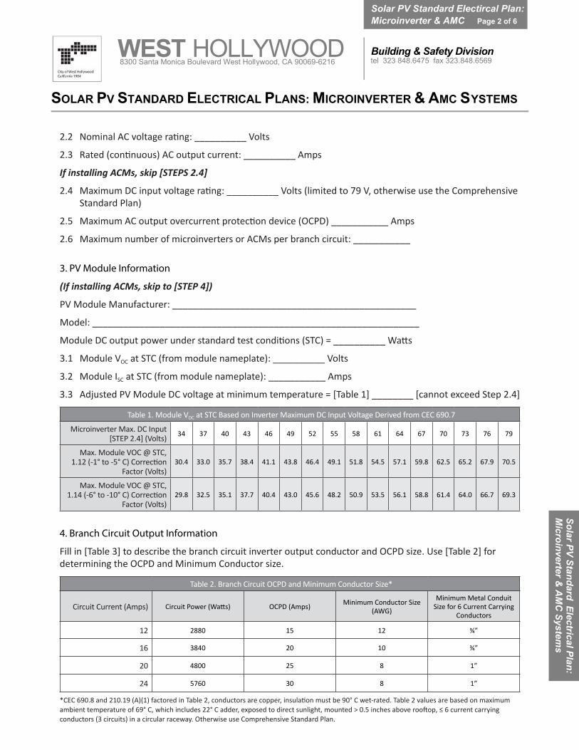
3. PV Module Information
(If installing ACMs, skip to [STEP 4])
PV Module Manufacturer: _______________________________________________
Model: _______________________________________________________________
Module DC output power under standard test conditions (STC) = __________ Watts
3.1 Module VOC at STC (from module nameplate): __________ Volts
3.2 Module ISC at STC (from module nameplate): ___________ Amps
3.3 Adjusted PV Module DC voltage at minimum temperature = [Table 1] ________ [cannot exceed Step 2.4]
Table 1. Module VOC at STC Based on Inverter Maximum DC Input Voltage Derived from CEC 690.7
Microinverter Max. DC Input [STEP 2.4] (Volts) 34 37 40 43 46 49 52 55 58 61 64 67 70 73 76 79
Max. Module VOC @ STC, 1.12 (-1° to -5° C) Correction
Factor (Volts)30.4 33.0 35.7 38.4 41.1 43.8 46.4 49.1 51.8 54.5 57.1 59.8 62.5 65.2 67.9 70.5
Max. Module VOC @ STC, 1.14 (-6° to -10° C) Correction
Factor (Volts)29.8 32.5 35.1 37.7 40.4 43.0 45.6 48.2 50.9 53.5 56.1 58.8 61.4 64.0 66.7 69.3
4. Branch Circuit Output Information
Fill in [Table 3] to describe the branch circuit inverter output conductor and OCPD size. Use [Table 2] for determining the OCPD and Minimum Conductor size.
Table 2. Branch Circuit OCPD and Minimum Conductor Size*
Circuit Current (Amps) OCPD (Amps) Minimum Conductor Size (AWG)
Minimum Metal Conduit Size for 6 Current Carrying
Conductors
12 2880 15 12 ¾”
16 3840 20 10 ¾”
20 4800 25 8 1”
24 5760 30 8 1”
*CEC 690.8 and 210.19 (A)(1) factored in Table 2, conductors are copper, insulation must be 90° C wet-rated. Table 2 values are based on maximum ambient temperature of 69° C, which includes 22° C adder, exposed to direct sunlight, mounted > 0.5 inches above rooftop, ≤ 6 current carrying conductors (3 circuits) in a circular raceway. Otherwise use Comprehensive Standard Plan.
WEST HOLLYWOOD 8300 Santa Monica Boulevard West Hollywood, CA 90069-6216
Solar PV Standard Electircal Plan: Microinverter & AMC Page 2 of 6
Building & Safety Division tel 323 848.6475 fax 323.848.6569
Solar PV Standard Electrical Plan: M
icroinverter & A
MC
Systems
SOLAR PV STANDARD ELECTRICAL PLANS: MICROINVERTER & AMC S YSTEMS
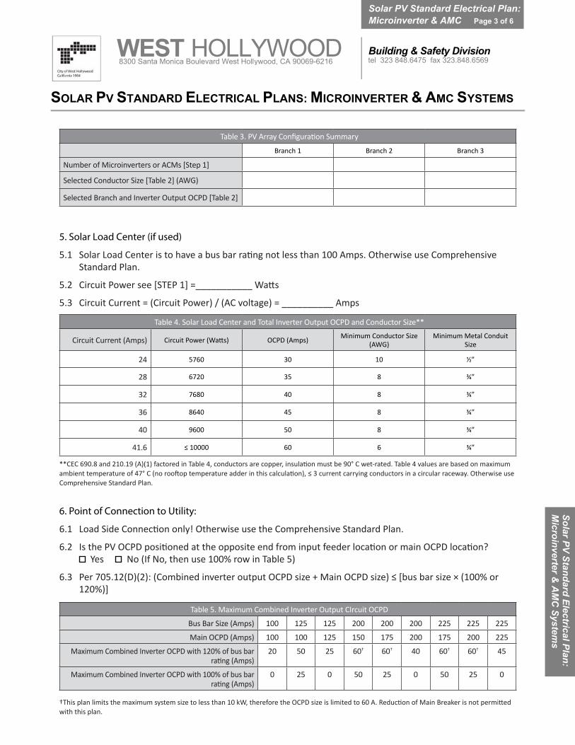
Table 3. PV Array Configuration Summary
Branch 1 Branch 2 Branch 3
Number of Microinverters or ACMs [Step 1]
Selected Conductor Size [Table 2] (AWG)
Selected Branch and Inverter Output OCPD [Table 2]
5. Solar Load Center (if used)
5.1 Solar Load Center is to have a bus bar rating not less than 100 Amps. Otherwise use ComprehensiveStandard Plan.
5.2 Circuit Power see [STEP 1] =___________ Watts
5.3 Circuit Current = (Circuit Power) / (AC voltage) = __________ Amps
Table 4. Solar Load Center and Total Inverter Output OCPD and Conductor Size**
Circuit Current (Amps) OCPD (Amps) Minimum Conductor Size (AWG)
Minimum Metal Conduit Size
24 5760 30 10 ½”
28 6720 35 8 ¾”
32 7680 40 8 ¾”
36 8640 45 8 ¾”
40 9600 50 8 ¾”
41.6 ≤ 10000 60 6 ¾”
**CEC 690.8 and 210.19 (A)(1) factored in Table 4, conductors are copper, insulation must be 90° C wet-rated. Table 4 values are based on maximum ambient temperature of 47° C (no rooftop temperature adder in this calculation), ≤ 3 current carrying conductors in a circular raceway. Otherwise use Comprehensive Standard Plan.
6. Point of Connection to Utility:
6.1 Load Side Connection only! Otherwise use the Comprehensive Standard Plan.
6.2 Is the PV OCPD positioned at the opposite end from input feeder location or main OCPD location? Yes No (If No, then use 100% row in Table 5)
6.3 Per 705.12(D)(2): (Combined inverter output OCPD size + Main OCPD size) ≤ [bus bar size × (100% or 120%)]
Table 5. Maximum Combined Inverter Output CIrcuit OCPD
Bus Bar Size (Amps) 100 125 125 200 200 200 225 225 225
Main OCPD (Amps) 100 100 125 150 175 200 175 200 225
Maximum Combined Inverter OCPD with 120% of bus bar rating (Amps)
20 50 25 60† 60† 40 60† 60† 45
Maximum Combined Inverter OCPD with 100% of bus bar rating (Amps)
0 25 0 50 25 0 50 25 0
†This plan limits the maximum system size to less than 10 kW, therefore the OCPD size is limited to 60 A. Reduction of Main Breaker is not permitted with this plan.
WEST HOLLYWOOD 8300 Santa Monica Boulevard West Hollywood, CA 90069-6216
Solar PV Standard Electrical Plan: Microinverter & AMC Page 3 of 6
Building & Safety Division tel 323 848.6475 fax 323.848.6569
Solar PV Standard Electrical Plan: M
icroinverter & A
MC
Systems
SOLAR PV STANDARD ELECTRICAL PLANS: MICROINVERTER & AMC SYSTEMS
WES
TH
OLL
YWO
OD
Bui
ldin
g &
Saf
ety
Div
isio
n83
00 S
anta
Mon
ica
Bou
leva
rd W
est H
olly
woo
d, C
A 90
069-
6216
tel 3
23.8
48.6
475
fax
323.
848.
6569
Sola
r PV
Stan
dard
Pla
n:C
entr
al/S
trin
g In
vert
er
Pag
e 5
of 6
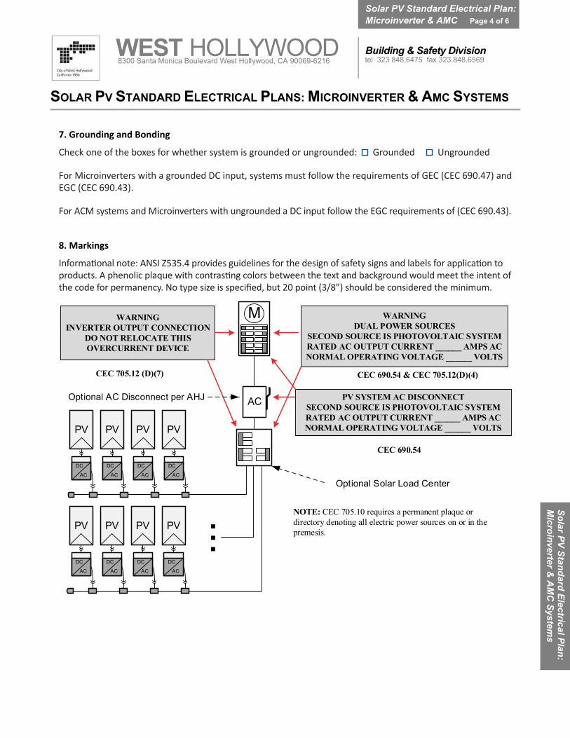
7. Grounding and Bonding
Check one of the boxes for whether system is grounded or ungrounded: Grounded Ungrounded
For Microinverters with a grounded DC input, systems must follow the requirements of GEC (CEC 690.47) and EGC (CEC 690.43).
For ACM systems and Microinverters with ungrounded a DC input follow the EGC requirements of (CEC 690.43).
8. Markings
Informational note: ANSI Z535.4 provides guidelines for the design of safety signs and labels for application to products. A phenolic plaque with contrasting colors between the text and background would meet the intent of the code for permanency. No type size is specified, but 20 point (3/8”) should be considered the minimum.
M
NOTE: CEC 705.10 requires a permanent plaque or directory denoting all electric power sources on or in the premesis.
CEC 690.54
CEC 690.54 & CEC 705.12(D)(4)
WARNINGDUAL POWER SOURCES
SECOND SOURCE IS PHOTOVOLTAIC SYSTEMRATED AC OUTPUT CURRENT ______ AMPS ACNORMAL OPERATING VOLTAGE ______ VOLTS
WARNINGINVERTER OUTPUT CONNECTION
DO NOT RELOCATE THISOVERCURRENT DEVICE
AC
DC
PV
AC
DC
PV
AC
DC
PV
AC
DC
PV
Optional AC Disconnect per AHJ PV SYSTEM AC DISCONNECTSECOND SOURCE IS PHOTOVOLTAIC SYSTEMRATED AC OUTPUT CURRENT ______ AMPS ACNORMAL OPERATING VOLTAGE ______ VOLTS
Optional Solar Load Center
AC
DC
PV
AC
DC
PV
AC
DC
PV
AC
DC
PV
AC
...
CEC 705.12 (D)(7)
WEST HOLLYWOOD 8300 Santa Monica Boulevard West Hollywood, CA 90069-6216
Solar PV Standard Electrical Plan: Microinverter & AMC Page 4 of 6
Building & Safety Division tel 323 848.6475 fax 323.848.6569
Solar PV Standard Electrical Plan: M
icroinverter & A
MC
Systems
SOLAR PV STANDARD ELECTRICAL PLANS: MICROINVERTER & AMC SYSTEMS
Sola
r PV
Stan
dard
Pla
n —
Sim
pli�
edCe
ntra
l/Str
ing
Inve
rter
Sys
tem
s fo
r One
- and
Tw
o-Fa
mily
Dw
ellin
gs
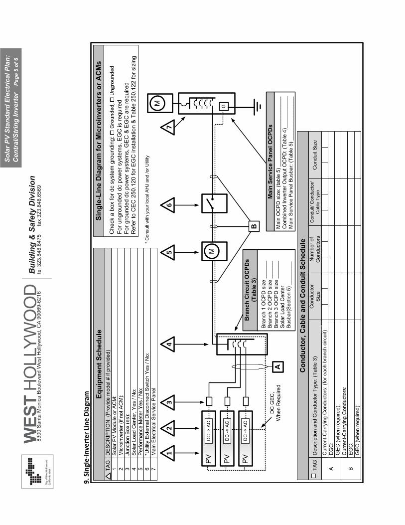
9.Si
ngle
-Inve
rter
Lin
e D
iagr
am
PV
DC
-> A
C
PV
DC
-> A
C
PV
DC
-> A
C
Sol
ar P
V M
odul
e or
AC
M:
DE
SC
RIP
TIO
N: (
Pro
vide
mod
el #
if p
rovi
ded)
Mic
roin
verte
r (if
not A
CM
):Ju
nctio
n B
ox (e
s):
Sol
ar L
oad
Cen
ter,
Yes
/ N
o:P
erfo
rman
ce M
eter
Yes
/ N
o:*U
tility
Ext
erna
l Dis
conn
ect S
witc
h Y
es /
No:
TAG
1 2 3 4 5 6
1
Sing
le-L
ine
Dia
gram
for M
icro
inve
rter
s or
AC
Ms
A
B
GM
M
45
67
2
Mai
n O
CP
D s
ize:
(tab
le 5
) ___
____
____
____
____
____
_ C
ombi
ned
Inve
rter O
utpu
t OC
PD
: (Ta
ble
4)__
____
____
_ M
ain
Ser
vice
Pan
el B
usba
r: (T
able
5) _
____
____
____
__
Equi
pmen
t Sch
edul
e
Bra
nch
Circ
uit O
CPD
s (T
able
3)
Mai
n Se
rvic
e Pa
nel O
CPD
sD
C G
EC
,W
hen
Req
uire
d
3
Bra
nch
1 O
CP
D s
ize
____
__B
ranc
h 2
OC
PD
siz
e __
____
Bra
nch
3 O
CP
D s
ize
____
__S
olar
Loa
d C
ente
r B
usba
r(S
ectio
n 5)
___
____
_
Che
ck a
box
for d
c sy
stem
gro
undi
ng: □
Gro
unde
d, □
Ung
roun
ded
For u
ngro
unde
d dc
pow
er s
yste
ms,
EG
C is
requ
ired
For g
roun
ded
dc p
ower
sys
tem
s, G
EC
& E
GC
are
requ
ired
Ref
er to
CE
C 2
50.1
20 fo
r EG
C in
stal
latio
n &
Tab
le 2
50.1
22 fo
r siz
ing
Des
crip
tion
and
Con
duct
or T
ype:
(Tab
le 3
)
Cur
rent
-Car
ryin
g C
ondu
ctor
s: (f
or e
ach
bran
ch c
ircui
t)
TAG
A
Con
duct
orS
ize
Con
duit/
Con
duct
or/
Cab
le T
ype
Con
duit
Siz
e
EG
C:
Con
duct
or, C
able
and
Con
duit
Sche
dule
mm
b
GE
C (w
hen
requ
ired)
:C
urre
nt-C
arry
ing
Con
duct
ors:
BE
GC
:G
EC
(whe
n re
quire
d):
Num
ber o
f C
ondu
ctor
s
* C
onsu
lt w
ith y
our l
ocal
AH
J an
d /o
r Util
ity7
Mai
n E
lect
rical
Ser
vice
Pan
el
9.Si
ngle
-Inve
rter
Lin
e Di
agra
m
WES
TH
OLL
YWO
OD
Bui
ldin
g &
Saf
ety
Div
isio
n83
00 S
anta
Mon
ica
Bou
leva
rd W
est H
olly
woo
d, C
A 90
069-
6216
tel 3
23.8
48.6
475
fax
323.
848.
6569
Sola
r PV
Stan
dard
Ele
ctric
al P
lan:
C
entr
al/S
trin
g In
vert
er
Pag
e 5
of 6
SOLA
R P
V ST
AN
DA
RD
PLA
N —
SIM
PLIF
IED
Mic
roin
vert
er a
nd A
CM
Sys
tem
s fo
r One
- and
Tw
o-Fa
mily
Dw
ellin
gs
PLO
T PL
AN
AN
D R
OO
F LA
YOU
T PL
AN
Item
s re
quire
d: P
rope
rty
line
loca
tions
, dim
ensi
ons
from
ex
terio
r wal
ls to
pro
pert
y lin
es, r
oof l
ayou
t of a
ll pa
nels
, m
odul
es, c
lear
acc
ess
path
way
s an
d ap
prox
imat
e lo
catio
ns o
f el
ectr
ical
dis
conn
ectin
g m
eans
and
roof
acc
ess
poin
ts.
Sola
r PV
Stan
dard
Ele
ctric
al P
lan:
C
entr
al/S
trin
g In
vert
er
Pag
e 6
of 6