oled pixel measurement & correction · 9/14/2017 · • all oled displays exhibit pixel-level...
TRANSCRIPT
Radiant Vision Systems | A Konica Minolta Company
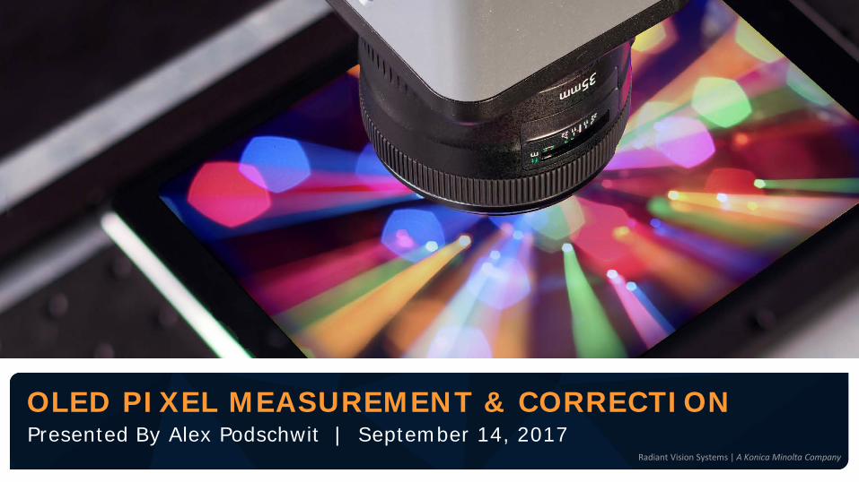
Presented By Alex Podschwit | September 14, 2017OLED PIXEL MEASUREMENT & CORRECTION

Global SupportAutomated Visual InspectionLight & Color

3Radiant Vision Systems | A Konica Minolta Company
© Radiant Vision Systems, LLC.
TODAY’S AGENDA
• The Rise of OLED in Displays
• OLED Drives New Inspection Challenges
• Methods for Pixel-Level Measurement of OLED Displays• Automated Visual Inspection
• Measuring High-Resolution Displays
• The Measurement Process
• Pixel-Level Correction (Demura)

THE RISE OF OLED IN DISPLAYS

5Radiant Vision Systems | A Konica Minolta Company
© Radiant Vision Systems, LLC.
Smartphones & Tablets Televisions AR/VR Wearables
ORGANIC LIGHT-EMITTING DIODE (OLED) TECHNOLOGY IN DISPLAYS
6Radiant Vision Systems | A Konica Minolta Company
© Radiant Vision Systems, LLC.
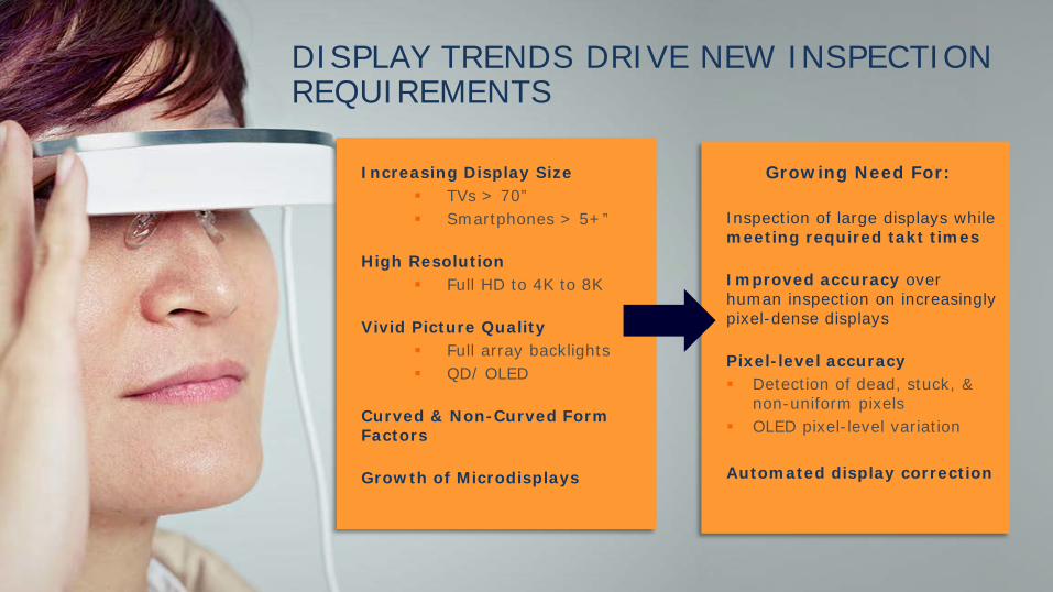
DISPLAY TRENDS DRIVE NEW INSPECTION REQUIREMENTS
Increasing Display Size TVs > 70” Smartphones > 5+”
High Resolution Full HD to 4K to 8K
Vivid Picture Quality Full array backlights QD/ OLED
Curved & Non-Curved Form Factors
Growth of Microdisplays
Inspection of large displays while meeting required takt times
Improved accuracy over human inspection on increasingly pixel-dense displays
Pixel-level accuracy Detection of dead, stuck, &
non-uniform pixels OLED pixel-level variation
Automated display correction
Growing Need For:

7Radiant Vision Systems | A Konica Minolta Company
© Radiant Vision Systems, LLC.
OLED INTRODUCES NEW CHALLENGES
• Pixel-level variation
• Color dependence on brightness
• Regional non-uniformity (mura) at low grey levels

8Radiant Vision Systems | A Konica Minolta Company
© Radiant Vision Systems, LLC.
WHITE OLED DISPLAY

9Radiant Vision Systems | A Konica Minolta Company
© Radiant Vision Systems, LLC.
• At high grey levels (bright display), there is strong pixel-level variation, which is noticeable to the observer.
PIXEL-LEVEL VARIATION

10Radiant Vision Systems | A Konica Minolta Company
© Radiant Vision Systems, LLC.
COLOR DEPENDENCE ON GREY LEVEL• Response over grey level is different for the red, green, and blue emitters for the
same pixel within an OLED display.
• This response can lead to an overall white point change of the display over grey level, as well as on the pixel level.
0
0.1
0.2
0.3
0.4
0.5
0.6
0.7
0.8
0.9
1
0 16 32 48 64 80 96 112
128
144
160
176
192
208
224
240
255
Nor
mal
ized
Lum
inan
ce (
NA)
Grey Level
Red
Green
Blue
0.25
0.3
0.35
0.4
0.45
0.5
0.55
16 32 48 64 80 96 112
128
144
160
176
192
208
224
240
255
Chr
omat
icity
Coo
rdin
ate
Grey Level
Cx
Cy
11Radiant Vision Systems | A Konica Minolta Company
© Radiant Vision Systems, LLC.
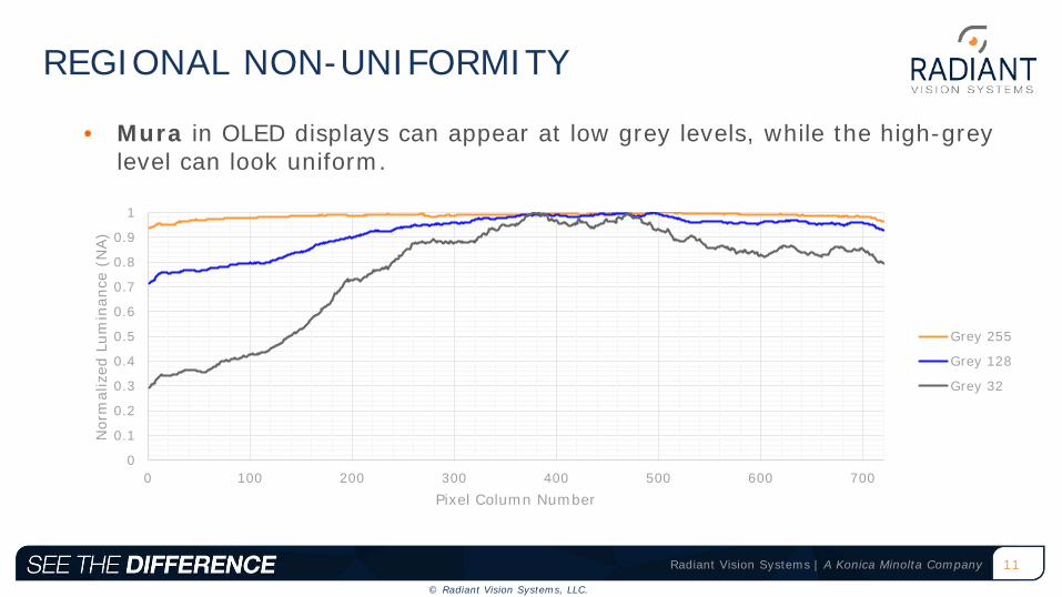
REGIONAL NON-UNIFORMITY
• Mura in OLED displays can appear at low grey levels, while the high-grey level can look uniform.
0
0.1
0.2
0.3
0.4
0.5
0.6
0.7
0.8
0.9
1
0 100 200 300 400 500 600 700
Nor
mal
ized
Lum
inan
ce (
NA)
Pixel Column Number
Grey 255
Grey 128
Grey 32
12Radiant Vision Systems | A Konica Minolta Company
© Radiant Vision Systems, LLC.
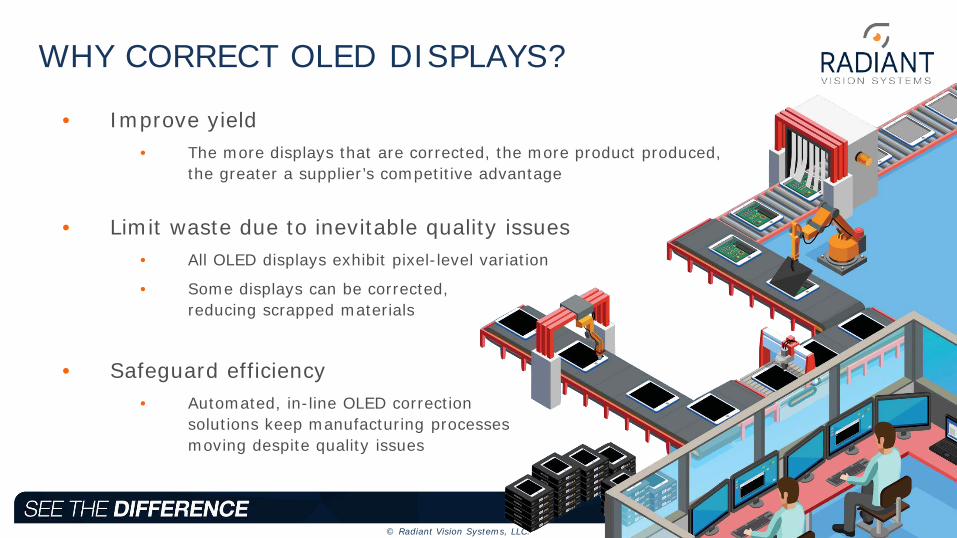
WHY CORRECT OLED DISPLAYS?
• Improve yield• The more displays that are corrected, the more product produced,
the greater a supplier’s competitive advantage
• Limit waste due to inevitable quality issues• All OLED displays exhibit pixel-level variation
• Some displays can be corrected, reducing scrapped materials
• Safeguard efficiency• Automated, in-line OLED correction
solutions keep manufacturing processes moving despite quality issues

13Radiant Vision Systems | A Konica Minolta Company
© Radiant Vision Systems, LLC.
METHODS FOR PIXEL-LEVEL MEASUREMENT OF OLED DISPLAYS

14Radiant Vision Systems | A Konica Minolta Company
© Radiant Vision Systems, LLC.
AUTOMATED VISUAL INSPECTION…
• is proven for testing and grading displays
• consists of an imaging colorimeter and analysis software
• replaces human inspectors
• pin-points and quantifies quality issues and defects
• allows pass/fail determinations to be automated against a consistent standard

15Radiant Vision Systems | A Konica Minolta Company
© Radiant Vision Systems, LLC.
MEASUREMENT REQUIREMENTSA 29MP imaging colorimeter can be used to measure a display size up to 1920x1080.
Pitfalls of Alternative Solutions:
• Low-resolution CCD sensors will suffer from aliasing
• When synthetic pixels are sampled with this low resolution, the luminance deviation approaches ±10%
• Larger-resolution sensors exist (>29MP)
• Today these sensors have insufficient SNR for accurate luminance and chromaticity measurement
If the display resolution is greater, we recommend:
• Multiple 29MP imaging colorimeters
• Spaced Pixel Test Patterns (US Patent 9135851)

16Radiant Vision Systems | A Konica Minolta Company
© Radiant Vision Systems, LLC.
• Employs several 29MP imaging colorimeters with high signal-to-noise ratio (SNR) to measure displays with resolution higher than 1920x1080.
• Software combines the measurement results of these multiple imaging colorimeters, post-processes, and factorsinto a Synthetic Measurement.
• Synthetic Measurement represents 1 Measurement Pixel = 1 Display Pixel
MULTIPLE IMAGING COLORIMETER SOLUTION

17Radiant Vision Systems | A Konica Minolta Company
© Radiant Vision Systems, LLC.
dot matrix test pattern
Pattern 1 Pattern 2 Pattern 3 Pattern 4
• The other test patterns are similar, but with different display pixels turned ON.
• In this example it will take 9x test patterns to ensure that every display pixels is turned ON one time.
• In this method, a series of dot-matrix test patterns will be shown on the display.
• Each pattern has only a small portion of the display pixels turned ON (rest is OFF).
Pattern 9
SPACED PIXEL TEST PATTERNS
18Radiant Vision Systems | A Konica Minolta Company
© Radiant Vision Systems, LLC.
THE MEASUREMENT PROCESS

19Radiant Vision Systems | A Konica Minolta Company
© Radiant Vision Systems, LLC.
PIXEL MEASUREMENT STEPSRaw Images Synthetic Images Concatenated Image

20Radiant Vision Systems | A Konica Minolta Company
© Radiant Vision Systems, LLC.
Software automatically registers the ON-pixels and places Regions-of-Interest (ROI) on each ON-pixel, measuring the pixel luminance and color.
ROIs are placed on the registered ON-pixelsThis measurement is repeated for the different dot-matrix patterns until each display pixel is analyzed.
Each display pixel is tested by many CCD pixels, producing an accurate measurement
AUTO-REGISTRATION OF THE ON-PIXELS
Example from Radiant TrueTest™ Software.

21Radiant Vision Systems | A Konica Minolta Company
© Radiant Vision Systems, LLC.
OLED Laptop
OLED Phone 1
OLED Phone 2
OLED Phone 3
OLED Phone 4
OLED Watch 1
OLED Watch 2
LCD Phone 1
FOV: 250um (Full White )
Resolution 2560 x 1440 1440 x 2560 1080 x 1920 1080 x 1920 1080 x 1920 390 x 312 400 x 400 1080 x 1920
Pixel pitch X 0.12 mm 0.05 mm 0.10 mm 0.13 mm 0.07 mm 0.08 mm 0.09 mm 0.08 mm
Pixel pitch Y 0.12 mm 0.05 mm 0.13 mm 0.13 mm 0.07 mm 0.08 mm 0.09 mm 0.08 mm
RGB primary observations at 20% brightness
R = R+GG = G+R+B
No isolated primaries
R = R+G+B G = G+R+B
SUB-PIXEL LAYOUT SUMMARY
Every OLED device arranges pixels differently, with respect to layout and resolution.

22Radiant Vision Systems | A Konica Minolta Company
© Radiant Vision Systems, LLC.
The obtained luminance & color values are combined in a Synthetic Image showing all the displays’ pixel rows and columns.
Synthetic Image: 1 Measurement Pixel = 1 Display Pixel
Synthetic Image
row
s
display columns
PASS / FAIL testing on luminance values can be applied to find pixel defects.
The location of pixel defects is reported in its row & column number.
SYNTHETIC IMAGE

23Radiant Vision Systems | A Konica Minolta Company
© Radiant Vision Systems, LLC.
OLED Phone 1 Device A
OLED Phone 1 Device B
OLED Phone 1 Device C OLED Phone 2 LCD Phone 1
Synthetic Image and Cross Section
Luminance Coefficient of Variation * 2.32% 2.81% 2.57% 2.36% 0.61%Cx Average * 0.309 0.303 0.300 0.296 0.306
Cx Standard Deviation * 0.004 0.003 0.003 0.003 0.000
Cy Average * 0.321 0.333 0.351 0.318 0.321
Cy Standard Deviation * 0.005 0.005 0.005 0.004 0.001
RESULTS COMPARISON: DEVICE TO DEVICE
* Note: Low frequency variation removed

24Radiant Vision Systems | A Konica Minolta Company
© Radiant Vision Systems, LLC.
MEASUREMENT RESULTS
• Luminance and color of each display pixel is measured with high accuracy
• Weak stuck-ON/OFF subpixels are easily found and accurately tested
• Different Pass/Fail thresholds can be applied for the different sub-pixels
• The location of display pixels is reported in (Column, Row) coordinates
• Sub-pixels can be tested by using test patterns in the different primary colors (RGB)

25Radiant Vision Systems | A Konica Minolta Company
© Radiant Vision Systems, LLC.
NON-UNIFORMITY CAN BE CORRECTED!
AfterBefore
Actual OLED Display Measurements

26Radiant Vision Systems | A Konica Minolta Company
© Radiant Vision Systems, LLC.
PIXEL-LEVEL CORRECTION USING RADIANT’S DEMURA SOLUTION

27Radiant Vision Systems | A Konica Minolta Company
© Radiant Vision Systems, LLC.
WHAT IS “DEMURA”?
• Even when OLED pixels receive the same electrical signal input, inconsistent luminance and chromaticity can occur from pixel to pixel
• These differences can be resolved using an in-line correction process called “Demura”
• Two steps to the Demura process:1. Use imaging colorimeters to evaluate and
quantify pixel uniformity issues
2. Apply grey-level passes to resolve uniformity based on precise pixel correction coefficients

28Radiant Vision Systems | A Konica Minolta Company
© Radiant Vision Systems, LLC.
IN-LINE APPLICATION1
2
Measure
Results
3 Correct
FIXABLE
FAIL
PA
SS

29Radiant Vision Systems | A Konica Minolta Company
© Radiant Vision Systems, LLC.
CORRECTION PROCESS
Select Imaging
ColorimeterTest Set-up Data
CollectionCompute Correction Coefficients
Transfer to OLED Screen
Controller
The correction process requires:
• measurement accuracy,
• measurement repeatability,
• careful definition of performance targets,
• compensation for OLED pixel and measurement geometries,
• and adjustment for human visual perception.

30Radiant Vision Systems | A Konica Minolta Company
© Radiant Vision Systems, LLC.
Measurement Hardware
• ProMetric® Imaging Photometer (Y29) or Colorimeter (I29)
• 29MP Sensor (6746 x 4384)
• Broad Dynamic Range (61.4 dB)
Demura Software
• TrueTest™ Demura Process
• Support for Multiple Pixel Layouts
• Proprietary Moiré Pattern Removal
• Grey-Level Correction Coefficients
• Fully-Documented API
RADIANT DEMURA SOLUTION

31Radiant Vision Systems | A Konica Minolta Company
© Radiant Vision Systems, LLC.
TrueTest DEMURA
SUPPORT FOR MULTIPLE PIXEL LAYOUTSLaptop Phone 1 Phone 2
Phone 3 Phone 4 Smart Watch

32Radiant Vision Systems | A Konica Minolta Company
© Radiant Vision Systems, LLC.
OLED PIXEL CORRECTION PROCEDURE
Utilize a high-resolution imaging colorimeter. Image right was captured with a Radiant 29MP imaging colorimeter.
• Register the sub-pixels within an image of the display
• The yellow ROI represents the location of pixels in the image
• Average the signal for each display’s sub-pixel over yellow ROI
• For each display’s sub-pixel compute luminance vs. grey level
• Compute a correction factor that will perform a uniformity correction for all grey levels

33Radiant Vision Systems | A Konica Minolta Company
© Radiant Vision Systems, LLC.
After Moiré removal
Before Moiré removal
• Display Resolution
• Photometer/Colorimeter Resolution
• Lens Design
• Filter
• Software Algorithm
Eliminate moiré due to:
TrueTest DEMURA
PROPRIETARY MOIRÉ PATTERN REMOVAL
Software capable of moiré removal ensures a clear image and enables more accurate pixel-level measurements.

34Radiant Vision Systems | A Konica Minolta Company
© Radiant Vision Systems, LLC.
GREY LEVEL CORRECTION COEFFICIENTS
Expected
Measured
Deviation
Lum
inan
ce (
Lv)
Gray Level (%)
0 (0%)
8 16 32 64 128 255(100%)

35Radiant Vision Systems | A Konica Minolta Company
© Radiant Vision Systems, LLC.
• Obtaining precise measurements of each pixel’s response over grey levels is critical to applying accurate correction coefficients for each grey level.
TrueTest DEMURA
GREY-LEVEL CORRECTION COEFFICIENTS
Video Signal In
Video Signal Out

36Radiant Vision Systems | A Konica Minolta Company
© Radiant Vision Systems, LLC.
RESULTS OF DEMURA UNIFORMITY IMPROVEMENT

37Radiant Vision Systems | A Konica Minolta Company
© Radiant Vision Systems, LLC.
CORRECTION: RED PIXELSBEFORE AFTER

38Radiant Vision Systems | A Konica Minolta Company
© Radiant Vision Systems, LLC.
CORRECTION: GREEN PIXELSBEFORE AFTER

39Radiant Vision Systems | A Konica Minolta Company
© Radiant Vision Systems, LLC.
CORRECTION: BLUE PIXELSBEFORE AFTER

40Radiant Vision Systems | A Konica Minolta Company
© Radiant Vision Systems, LLC.
CORRECTION: WHITE PIXELSBEFORE AFTER

41Radiant Vision Systems | A Konica Minolta Company
© Radiant Vision Systems, LLC.
CORRECTION RESULTS: ALL PIXELS
After Correction
Before Correction

42Radiant Vision Systems | A Konica Minolta Company
© Radiant Vision Systems, LLC.
SUMMARY
Pixel-level correction has a direct, positive impact on yield of advanced high-resolution OLED displays.
This is important in OLED because each pixel is an independent light emitter, which can behave and age differently than its neighboring pixels.
To perform pixel-level measurements, a colorimeter with very high resolution and high signal-to-noise ratio is critically important.
A Demura solution can be established in-line to measure and route devices based on the severity of mura, and then apply corrections to the fixable devices, reducing waste.

Radiant Vision Systems | A Konica Minolta CompanyRadiant Vision Systems | A Konica Minolta CompanyQuestions? Contact [email protected]
THANK YOU!