olfactory detector port op275 - ingenieria-analitica.com · this manual describes the op275...
TRANSCRIPT
Olfactory Detector Port OP275 Operations Manual
22-1 Nishishinjuku 6-chome, shinjuku-ku, Tokyo 163-1130,Japan
1
Please Read
・The copyright of this manual is the property of GL Sciences. This manual may not be reprinted in part or in full without permission.
・For improvement purposes, the content, specifications or appearance are subject to change
without notice.
・All care has been taken in the preparation of this document, however, should you discover any omissions or mistakes in the document please feel free to contact your nearest GL Sciences dealer for assistance.
Copyright 2007 GL Sciences Inc. This manual may not be reprinted or changed without permission from GL Sciences Inc.
About trademarks ☆Silcosteel® is a registered trademark of Restek Corporation. ☆Vespel® is a registered trademark of DuPont. ☆Windows® is a registered trademark of Microsoft. ☆Other company and product names appearing herein are trademarks or registered trademarks
of those companies respectively.
2
Thank you for purchasing the OP275 Olfactory Detector Port.
Preface This manual describes the OP275 Olfactory Detector Port options, functions, troubleshooting and operations. To ensure prolonged reliability and performance, be sure to thoroughly read this manual before installing and operating the instrument.
Attention! This manual contains essential information to ensure safe and correct operating procedures, and prolonged, reliable performance. Especially for safety considerations, pay close attention to the warnings and signals listed below as they appear in this manual.
Indicates that incorrect operation of the instrument can cause serious injury or death to the user.
Indicates that incorrect operation of the instrument can cause minor injury or damage.
Indicates that incorrect operation can result in damage to the instrument or adversely affect performance.
Indicates useful information or considerations regarding operation.
Warning
Attention!
Note!
Caution
3
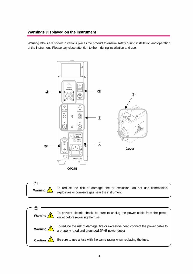
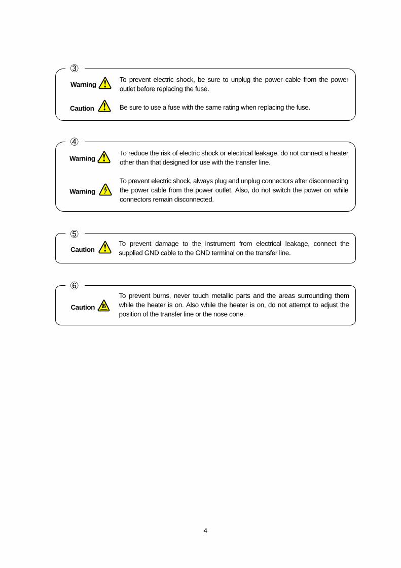
Warnings Displayed on the Instrument Warning labels are shown in various places the product to ensure safety during installation and operation of the instrument. Please pay close attention to them during installation and use.
To reduce the risk of damage, fire or explosion, do not use flammables,explosives or corrosive gas near the instrument.
①
To prevent electric shock, be sure to unplug the power cable from the poweroutlet before replacing the fuse.
To reduce the risk of damage, fire or excessive heat, connect the power cable toa properly rated and grounded 2P+E power outlet
Be sure to use a fuse with the same rating when replacing the fuse.
②
①
③
②⑤
④ ⑥
OP275
Cover
Warning
Warning
Warning
Caution
4
To prevent damage to the instrument from electrical leakage, connect thesupplied GND cable to the GND terminal on the transfer line.
⑤
To prevent electric shock, be sure to unplug the power cable from the power outlet before replacing the fuse.
Be sure to use a fuse with the same rating when replacing the fuse.
③
To reduce the risk of electric shock or electrical leakage, do not connect a heaterother than that designed for use with the transfer line.
To prevent electric shock, always plug and unplug connectors after disconnectingthe power cable from the power outlet. Also, do not switch the power on whileconnectors remain disconnected.
④
Warning
Warning
Caution
Caution
To prevent burns, never touch metallic parts and the areas surrounding themwhile the heater is on. Also while the heater is on, do not attempt to adjust theposition of the transfer line or the nose cone.
Caution
Warning
⑥
5
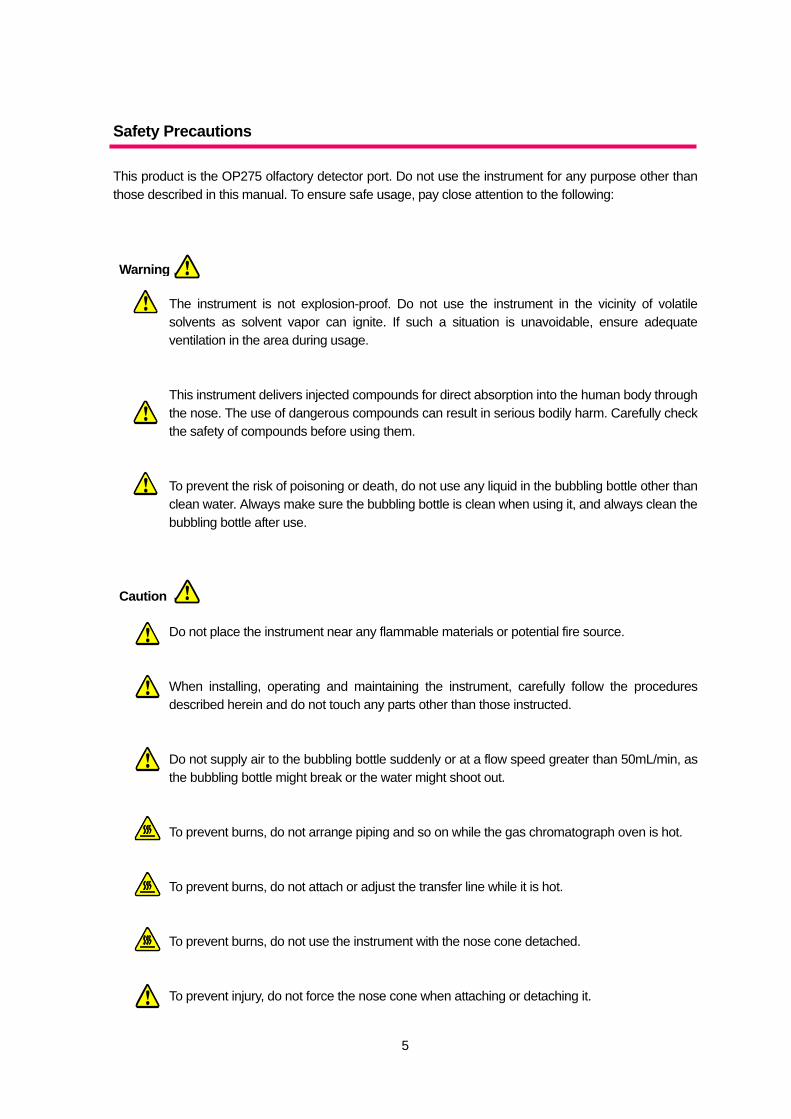
Safety Precautions This product is the OP275 olfactory detector port. Do not use the instrument for any purpose other than those described in this manual. To ensure safe usage, pay close attention to the following:
The instrument is not explosion-proof. Do not use the instrument in the vicinity of volatile solvents as solvent vapor can ignite. If such a situation is unavoidable, ensure adequate ventilation in the area during usage.
This instrument delivers injected compounds for direct absorption into the human body through the nose. The use of dangerous compounds can result in serious bodily harm. Carefully check the safety of compounds before using them.
To prevent the risk of poisoning or death, do not use any liquid in the bubbling bottle other than clean water. Always make sure the bubbling bottle is clean when using it, and always clean the bubbling bottle after use.
Do not place the instrument near any flammable materials or potential fire source.
When installing, operating and maintaining the instrument, carefully follow the procedures described herein and do not touch any parts other than those instructed.
Do not supply air to the bubbling bottle suddenly or at a flow speed greater than 50mL/min, as the bubbling bottle might break or the water might shoot out.
To prevent burns, do not arrange piping and so on while the gas chromatograph oven is hot.
To prevent burns, do not attach or adjust the transfer line while it is hot.
To prevent burns, do not use the instrument with the nose cone detached.
To prevent injury, do not force the nose cone when attaching or detaching it.
Warning
Caution
6
The smallest radius to which the transfer line can be bent is 70mm. Do not excessively bend or twist the transfer line as this can cause the heater line to break and result in electrical leakage.
・Do not store or use the instrument in an area that is hot, damp, dusty or subject to strong vibrations.
・Do not store or use the instrument in direct sunlight.
・Install the instrument on a stable flat surface.
・Do not use the instrument in an area where there is corrosive solvent or corrosive gas.
・Do not install the instrument near devices such as high powered circuit breakers or high
frequency furnaces that can cause power surges. Do not install the instrument near highly magnetic devices.
・Do not place objects on, or bend the power cable.
・Always check the piping for loose connections and leakage before use.
・Do not dismantle or modify any part of the instrument unless instructed in this manual.
・Do not adjust the internal parameters for the temperature control unit.
・For safety purposes, handling of organic solvents and so on must be carried out by persons
with knowledge in this field.
・If a problem arises with the instrument, stop usage immediately, and disconnect the power cable from the power outlet.
・Do not use the transfer line for any purpose other than those described in this manual.
・To avoid breakage, do not force the nose cone when attaching it or detaching it.
・Do not hold the transfer line by the flexible arm or protective cover when adjusting its position.
The protective cover might distort.
Attention!
7
CONTENTS Please Read ................................................................................................................................................. 1 Preface.......................................................................................................................................................... 2 Attention! ....................................................................................................................................................... 2
Warnings Displayed on the Instrument............................................................................................. 3 Safety Precautions ............................................................................................................................ 5
1. Overview................................................................................................................................................... 9 1-1. Olfactory Detector OP275.......................................................................................................... 9 1-2. Split Manager (Split Ratio Simulation Software)........................................................................ 9 1-3. Features.................................................................................................................................... 10
2. Unpacking/Installation Requirements..................................................................................................... 12 2-1. Unpacking................................................................................................................................. 12 2-2. Installation Requirements......................................................................................................... 12
3. Preparation ............................................................................................................................................. 13 3-1. Preparing the Stabilizers .......................................................................................................... 13 3-2. Checking the Gas Chromatograph Type................................................................................. 14 3-3. Checking the Transfer Line Attachment Point ......................................................................... 15 3-4. Checking the Gas Supply and Piping...................................................................................... 17
4. Parts, Names and Functions.................................................................................................................. 19 4-1. Controller Front Panel .............................................................................................................. 19 4-2. Controller Rear Panel............................................................................................................... 21 4-3. Transfer Line............................................................................................................................. 23
5. Attaching the Transfer Line..................................................................................................................... 25 5-1. Securing the GC holder............................................................................................................ 25 5-2. Adjusting the Transfer Line Position......................................................................................... 26 5-3. Using the Mount System.......................................................................................................... 26 5-4. Using the Arm Stand ................................................................................................................ 28 5-5. GC-4000 and G-6000 .............................................................................................................. 29 5-6. HP/Agilent 6890 ....................................................................................................................... 30
5-6-1. Installation on the Left ............................................................................................ 31 5-6-2. Installation on the Top ............................................................................................ 32
5-7. Shimadzu GC-2010 ................................................................................................................. 33 5-8. Shimadzu GC-17A................................................................................................................... 35
5-8-1. Shimadzu GC-17A................................................................................................. 36 5-8-2. Ver.1 Installation on the Left................................................................................... 36 5-8-3. Ver.2 or 3 Installation on the Left............................................................................ 37 5-8-4. Ver.2 or 3 Installation on the Top............................................................................ 38
6. Splitter Connection.................................................................................................................................. 40 6-1. Connection Method.................................................................................................................. 40 6-2. Removing Ferrules................................................................................................................... 43
7. Preparation ............................................................................................................................................. 44 7-1. Preparing the Bubbling Bottle .................................................................................................. 44 7-2. Adjusting the AUX GAS flow .................................................................................................... 45 7-3. Preparing the Transfer Line...................................................................................................... 45 7-4. Temperature Settings ............................................................................................................... 46
8. Operating the Temperature Control Unit ................................................................................................ 47 8-1. Display Items and Functions.................................................................................................... 47 8-2. Reading the Display ................................................................................................................. 48 8-3. Temperature Settings ............................................................................................................... 49
8
9. Split Manager Split Ratio Simulation Software....................................................................................... 50 9-1. Functions .................................................................................................................................. 50 9-2. Set Up....................................................................................................................................... 50 9-3. Screen descriptions.................................................................................................................. 51 9-4. Operation.................................................................................................................................. 52
9-4-1. Split Ratio Simulation ............................................................................................. 53 9-4-2. Capillary Tube Length Simulation.......................................................................... 53
10. Nose Guard (Option) ............................................................................................................................ 54 11. Maintenance ......................................................................................................................................... 55
11-1. Replacing the Fuse................................................................................................................. 55 11-2. Cleaning the Nose Cone........................................................................................................ 55
12. Troubleshooting .................................................................................................................................... 56 13. Utility specifications............................................................................................................................... 58
13-1. Olfactory Detector Port OP275.............................................................................................. 58 13-2. Split Manager (Split Ratio Simulation Software).................................................................... 59
14. Specifications........................................................................................................................................ 60 14-1. Olfactory Detector Port OP275.............................................................................................. 60
15. Packing List........................................................................................................................................... 62 15-1. Olfactory Detector Port OP275.............................................................................................. 62 15-2. Options ................................................................................................................................... 62
16. Parts/Expendables ............................................................................................................................... 64
9
1. Overview
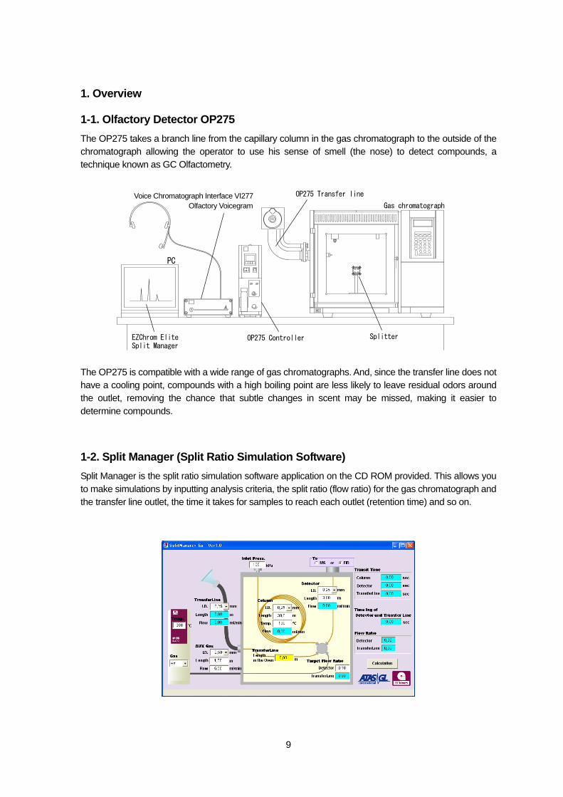
1-1. Olfactory Detector OP275 The OP275 takes a branch line from the capillary column in the gas chromatograph to the outside of the chromatograph allowing the operator to use his sense of smell (the nose) to detect compounds, a technique known as GC Olfactometry. The OP275 is compatible with a wide range of gas chromatographs. And, since the transfer line does not have a cooling point, compounds with a high boiling point are less likely to leave residual odors around the outlet, removing the chance that subtle changes in scent may be missed, making it easier to determine compounds.
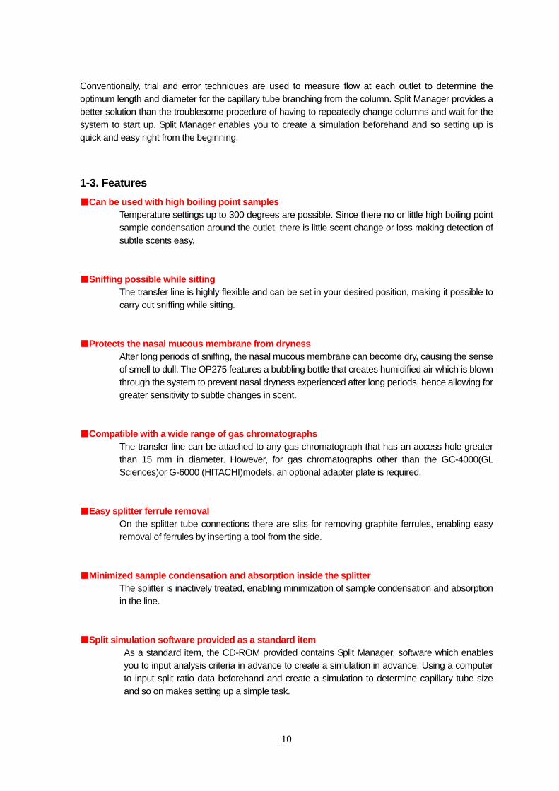
1-2. Split Manager (Split Ratio Simulation Software) Split Manager is the split ratio simulation software application on the CD ROM provided. This allows you to make simulations by inputting analysis criteria, the split ratio (flow ratio) for the gas chromatograph and the transfer line outlet, the time it takes for samples to reach each outlet (retention time) and so on.
Gas chromatograph
OP275 Transfer line
Splitter OP275 Controller Split ManagerEZChrom Elite
PC
Voice Chromatograph Interface VI277 Olfactory Voicegram
10
Conventionally, trial and error techniques are used to measure flow at each outlet to determine the optimum length and diameter for the capillary tube branching from the column. Split Manager provides a better solution than the troublesome procedure of having to repeatedly change columns and wait for the system to start up. Split Manager enables you to create a simulation beforehand and so setting up is quick and easy right from the beginning.
1-3. Features ■Can be used with high boiling point samples
Temperature settings up to 300 degrees are possible. Since there no or little high boiling point sample condensation around the outlet, there is little scent change or loss making detection of subtle scents easy.
■Sniffing possible while sitting
The transfer line is highly flexible and can be set in your desired position, making it possible to carry out sniffing while sitting.
■Protects the nasal mucous membrane from dryness
After long periods of sniffing, the nasal mucous membrane can become dry, causing the sense of smell to dull. The OP275 features a bubbling bottle that creates humidified air which is blown through the system to prevent nasal dryness experienced after long periods, hence allowing for greater sensitivity to subtle changes in scent.
■Compatible with a wide range of gas chromatographs
The transfer line can be attached to any gas chromatograph that has an access hole greater than 15 mm in diameter. However, for gas chromatographs other than the GC-4000(GL Sciences)or G-6000 (HITACHI)models, an optional adapter plate is required.
■Easy splitter ferrule removal
On the splitter tube connections there are slits for removing graphite ferrules, enabling easy removal of ferrules by inserting a tool from the side.
■Minimized sample condensation and absorption inside the splitter
The splitter is inactively treated, enabling minimization of sample condensation and absorption in the line.
■Split simulation software provided as a standard item
As a standard item, the CD-ROM provided contains Split Manager, software which enables you to input analysis criteria in advance to create a simulation in advance. Using a computer to input split ratio data beforehand and create a simulation to determine capillary tube size and so on makes setting up a simple task.
11
■Nose cone scent residue reduced to a minimum When using high boiling point samples, samples can condense or become absorbed inside the conventional GC-O nose cone. This means that the operator often removes the nose cone and continues sniffing, which often results in burns to the nose. To solve this problem, the optional Nose Guard is available for the OP275, a nose cone featuring ventilation slits in the upper and lower part of the nose cone. The Nose Guard serves to reduce scent residue in the nose cone to a minimum, and act as a protector to prevent operator nose burns.
■Compact design
The controller features a compact design with the temperature control, flow control and bubbling bottle holder all contained in one unit. The external dimensions W96×H300×D230 mm enable the instrument to be set up in confined spaces.
■Bubbling bottle cleansing possible
The bubbling bottle attached to the controller is removable, making it easy to clean and use in a hygienic state at all times.
12
2. Unpacking/Installation Requirements
2-1. Unpacking ◆This is a precision instrument that includes glass parts. Handle with care while unpacking.
①Open the package, and carefully remove the packing material. ②Make sure that there is no damage to the instrument or accessories. ③Make sure that all the items are included in the package. To check the items, see ’15.
Packing List’.
All care has been taken in ensuring correct product shipment, however, should you find missing items or abnormalities, Please contact you nearest dealer.
2-2. Installation Requirements Pay attention to the following when installing the instrument. ◆This instrument is not explosion proof.
Do not install the instrument in an area where there are volatile, flammable or corrosive substances, or organic solvents. Install the instrument on a flat stable surface. When using organic solvents, be sure to provide adequate ventilation, and ensure that the correct environmental requirements are met. Do not install the instrument in an area subject to drafts.
◆This product is designed for 200 to 240V AC, 50 to 60Hz(general power outlet)
To protect the instrument from lightning strike, electrical leakage, static electricity and so forth, Make sure the power cable is connected to a properly grounded 2P+E power outlet. Further, do not place the instrument near devices that can cause power surges such as a high power circuit breaker or high frequency furnace, nor place the instrument near devices that emulate strong magnetic fields.
◆The maximum power consumption is 500VA
Be sure that the power outlet to which the instrument is connected is suitably rated for the power consumption.
◆The transfer line outlet gets hot
The transfer line outlet and surrounding metallic parts get very hot. Do not use the device in areas where there is a lot of human traffic, or near flammable materials.
◆The instrument requires clean water
The controller uses clean water to provide humidified air. Do not place the controller on top of a gas chromatograph or electrical device. Water spillage from the instrument may result in damage to surrounding equipment.
13
3. Preparation
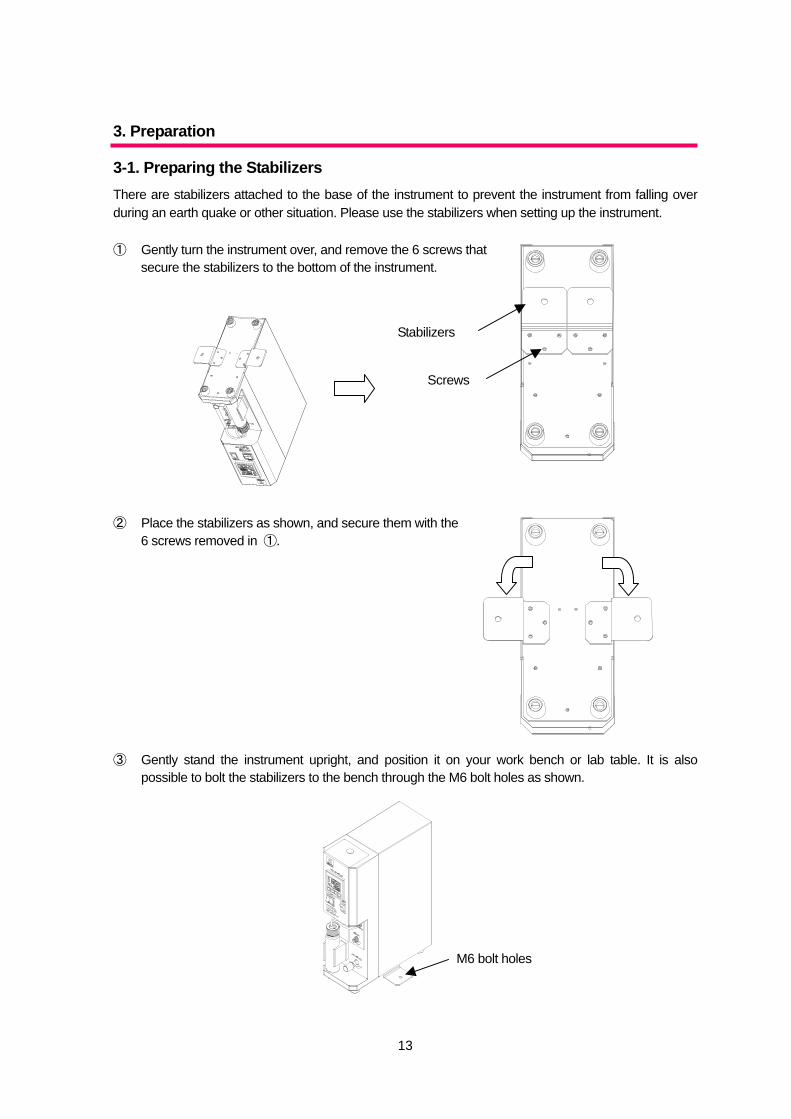
3-1. Preparing the Stabilizers There are stabilizers attached to the base of the instrument to prevent the instrument from falling over during an earth quake or other situation. Please use the stabilizers when setting up the instrument. ① Gently turn the instrument over, and remove the 6 screws that
secure the stabilizers to the bottom of the instrument. ② Place the stabilizers as shown, and secure them with the
6 screws removed in ①. ③ Gently stand the instrument upright, and position it on your work bench or lab table. It is also
possible to bolt the stabilizers to the bench through the M6 bolt holes as shown.
Stabilizers
Screws
M6 bolt holes
14
When installing, operating and maintaining the instrument, carefully follow the procedures described herein and do not touch any parts other than those instructed.
・ Install the instrument on a flat, stable surface. ・ Do not dismantle or modify any part of the instrument unless instructed in this
manual.
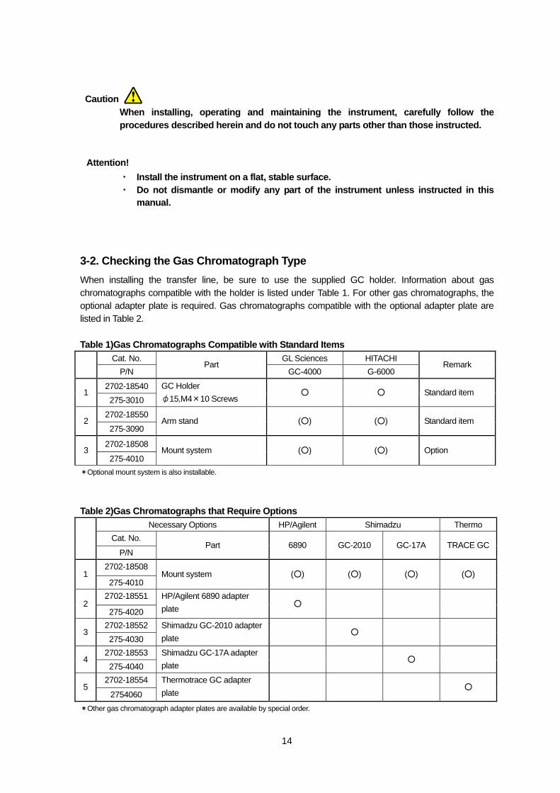
3-2. Checking the Gas Chromatograph Type When installing the transfer line, be sure to use the supplied GC holder. Information about gas chromatographs compatible with the holder is listed under Table 1. For other gas chromatographs, the optional adapter plate is required. Gas chromatographs compatible with the optional adapter plate are listed in Table 2. Table 1)Gas Chromatographs Compatible with Standard Items
Cat. No. GL Sciences HITACHI
P/N Part
GC-4000 G-6000 Remark
2702-18540 1
275-3010
GC Holder φ15,M4×10 Screws
○ ○ Standard item
2702-18550 2
275-3090 Arm stand (○) (○) Standard item
2702-18508 3
275-4010 Mount system (○) (○) Option
*Optional mount system is also installable.
Table 2)Gas Chromatographs that Require Options
Necessary Options HP/Agilent Shimadzu Thermo Cat. No.
P/N Part 6890 GC-2010 GC-17A TRACE GC
2702-18508 1
275-4010 Mount system (○) (○) (○) (○)
2702-18551 2
275-4020
HP/Agilent 6890 adapter plate ○
2702-18552 3
275-4030 Shimadzu GC-2010 adapter plate
○
2702-18553 4
275-4040 Shimadzu GC-17A adapter plate
○
2702-18554 5
2754060
Thermotrace GC adapter plate
○
*Other gas chromatograph adapter plates are available by special order.
Caution
Attention!
15
If an autosampler or mass spectrometer is set up in conjunction with the gas chromatograph, installation is may not be possible. Please check the type of gas chromatograph, installation point and connected peripheral equipment in advance.
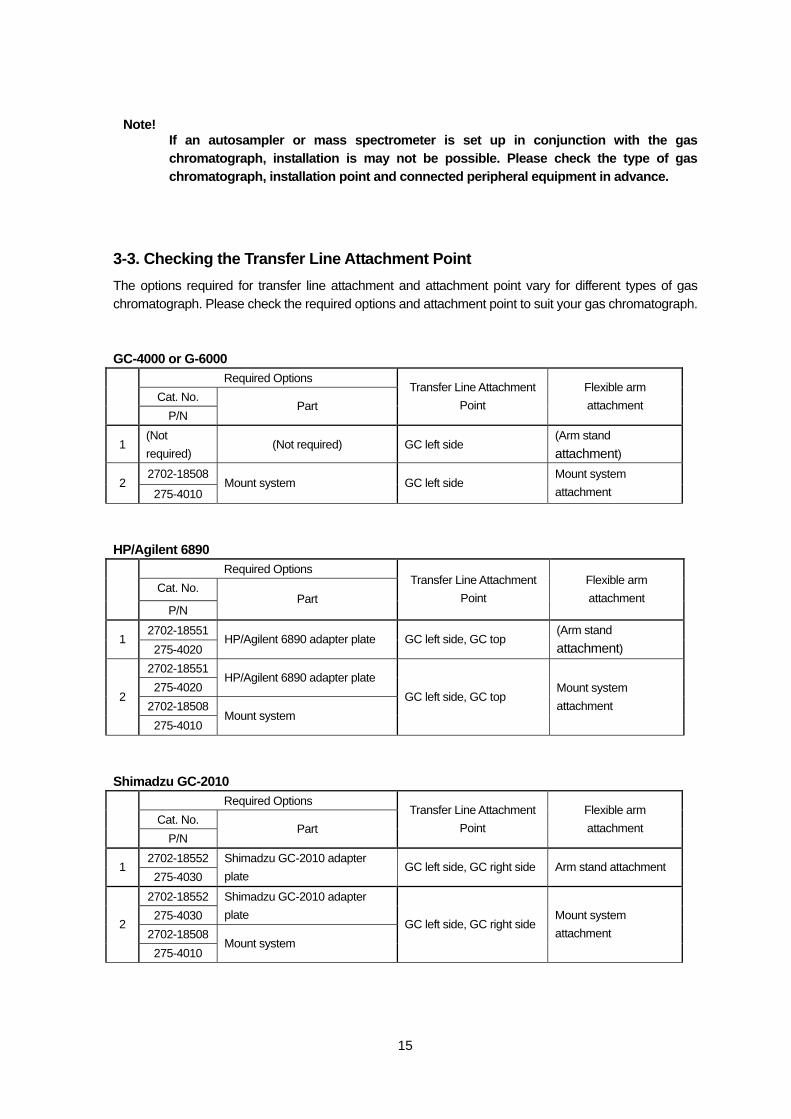
3-3. Checking the Transfer Line Attachment Point The options required for transfer line attachment and attachment point vary for different types of gas chromatograph. Please check the required options and attachment point to suit your gas chromatograph. GC-4000 or G-6000
Required Options Cat. No.
P/N Part
Transfer Line Attachment Point
Flexible arm attachment
1 (Not required)
(Not required) GC left side (Arm stand attachment)
2702-18508 2
275-4010 Mount system GC left side
Mount system attachment
HP/Agilent 6890
Required Options Cat. No.
P/N Part
Transfer Line Attachment Point
Flexible arm attachment
2702-18551 1
275-4020 HP/Agilent 6890 adapter plate GC left side, GC top
(Arm stand attachment)
2702-18551 275-4020
HP/Agilent 6890 adapter plate
2702-18508 2
275-4010 Mount system
GC left side, GC top Mount system attachment
Shimadzu GC-2010
Required Options Cat. No.
P/N Part
Transfer Line Attachment Point
Flexible arm attachment
2702-18552 1
275-4030 Shimadzu GC-2010 adapter plate
GC left side, GC right side Arm stand attachment
2702-18552 275-4030
Shimadzu GC-2010 adapter plate
2702-18508 2
275-4010 Mount system
GC left side, GC right side Mount system attachment
Note!
16
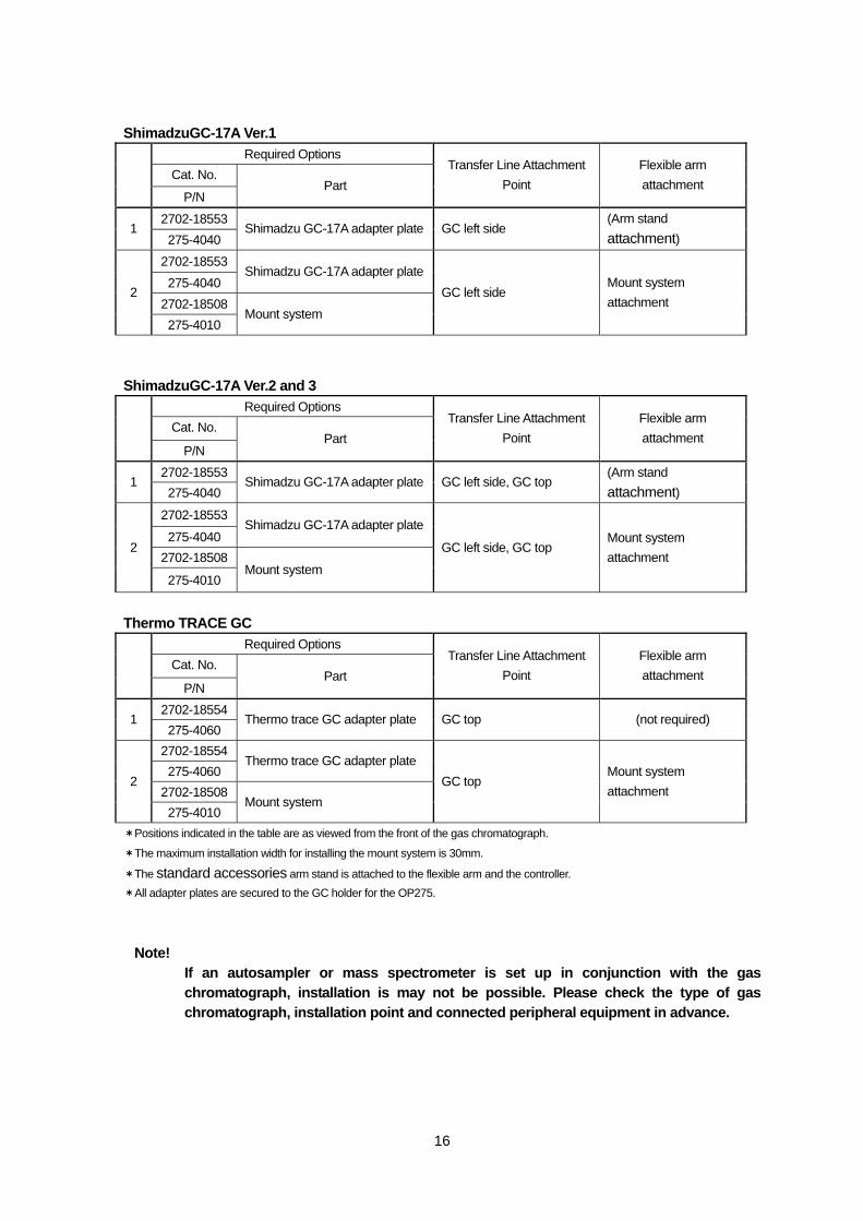
ShimadzuGC-17A Ver.1 Required Options
Cat. No.
P/N Part
Transfer Line Attachment Point
Flexible arm attachment
2702-18553 1
275-4040 Shimadzu GC-17A adapter plate GC left side
(Arm stand attachment)
2702-18553 275-4040
Shimadzu GC-17A adapter plate
2702-18508 2
275-4010 Mount system
GC left side Mount system attachment
ShimadzuGC-17A Ver.2 and 3
Required Options Cat. No.
P/N Part
Transfer Line Attachment Point
Flexible arm attachment
2702-18553 1
275-4040 Shimadzu GC-17A adapter plate GC left side, GC top
(Arm stand attachment)
2702-18553
275-4040 Shimadzu GC-17A adapter plate
2702-18508 2
275-4010 Mount system
GC left side, GC top Mount system attachment
Thermo TRACE GC
Required Options Cat. No.
P/N Part
Transfer Line Attachment Point
Flexible arm attachment
2702-18554 1
275-4060 Thermo trace GC adapter plate GC top (not required)
2702-18554 275-4060
Thermo trace GC adapter plate
2702-18508 2
275-4010 Mount system
GC top Mount system attachment
*Positions indicated in the table are as viewed from the front of the gas chromatograph.
*The maximum installation width for installing the mount system is 30mm.
*The standard accessories arm stand is attached to the flexible arm and the controller. *All adapter plates are secured to the GC holder for the OP275.
If an autosampler or mass spectrometer is set up in conjunction with the gas chromatograph, installation is may not be possible. Please check the type of gas chromatograph, installation point and connected peripheral equipment in advance.
Note!
17
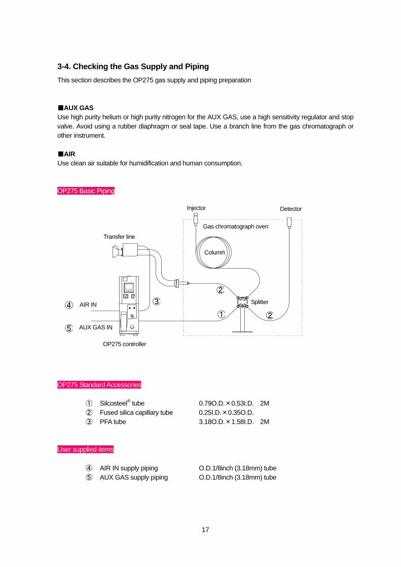
3-4. Checking the Gas Supply and Piping This section describes the OP275 gas supply and piping preparation ■AUX GAS Use high purity helium or high purity nitrogen for the AUX GAS, use a high sensitivity regulator and stop valve. Avoid using a rubber diaphragm or seal tape. Use a branch line from the gas chromatograph or other instrument. ■AIR Use clean air suitable for humidification and human consumption. OP275 Basic Piping OP275 Standard Accessories
① Silcosteel® tube 0.79O.D.×0.53I.D. 2M ② Fused silica capillary tube 0.25I.D.×0.35O.D. ③ PFA tube 3.18O.D.×1.58I.D. 2M
User supplied items
④ AIR IN supply piping O.D.1/8inch (3.18mm) tube ⑤ AUX GAS supply piping O.D.1/8inch (3.18mm) tube
⑤
AIR IN
Column
Detector Injector
Gas chromatograph oven
Splitter
Transfer line
OP275 controller
①
②
②
③④
AUX GAS IN
18
Do not use flammable, explosive or corrosive gas. Such gas may cause a fire, explosion or damage.
To prevent burns, do not arrange piping and so on while the gas chromatograph oven is hot.
Do not supply air to the bubbling bottle suddenly or at a flow speed greater than 50mL/min, as the bubbling bottle might break or the water might shoot out.
Be sure to inspect for gas leakage and loose piping before use.
Warning
Caution
Attention!
Caution
19
4. Parts, Names and Functions
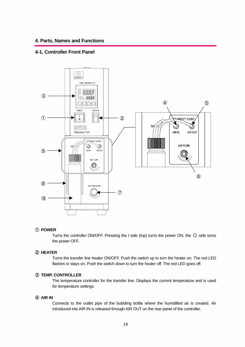
4-1. Controller Front Panel ① POWER
Turns the controller ON/OFF. Pressing the I side (top) turns the power ON, the ○ side turns the power OFF.
② HEATER
Turns the transfer line heater ON/OFF. Push the switch up to turn the heater on. The red LED flashes or stays on. Push the switch down to turn the heater off. The red LED goes off.
③ TEMP. CONTROLLER
The temperature controller for the transfer line. Displays the current temperature and is used for temperature settings.
④ AIR IN
Connects to the outlet pipe of the bubbling bottle where the humidified air is created. Air introduced into AIR IN is released through AIR OUT on the rear panel of the controller.
③
①
⑨
⑧
⑩
②
⑦
④ ⑤
⑥
20
⑤ AIR OUT Releases clean air introduced into AIR IN on the rear of the controller. Connects to the PFA tube attached to the filter inside the bubbling bottle.
⑥ AIR FLOW
Adjusts the air flow of clean air from the AIR OUT. Set the flow lower than 50mL/min. Rotate anticlockwise to increase flow, clockwise to decrease.
⑦ AUX GAS FLOW
Adjusts gas flow for AUX GAS introduced into the splitter. Set the flow to 5mL/min. Rotate anticlockwise to increase flow, clockwise to decrease. Since a mass flow valve is used, it takes a little time for the flow to stabilize.
⑧ BUBBLING BOTTLE HOLDER
The holder for the bubbling bottle where the humidified air is produced. Push the bubbling bottle in to secure it.
⑨ BUBBLING BOTTLE
The bottle that produces the humidified air. Air from AIR OUT bubbles inside the bottle to produce humidified air. Fill the bottle with less than 20m/l of clean water (about half full).
⑩ FILTER
Filter for clean air introduced into the bubbling bottle for bubbling.
21
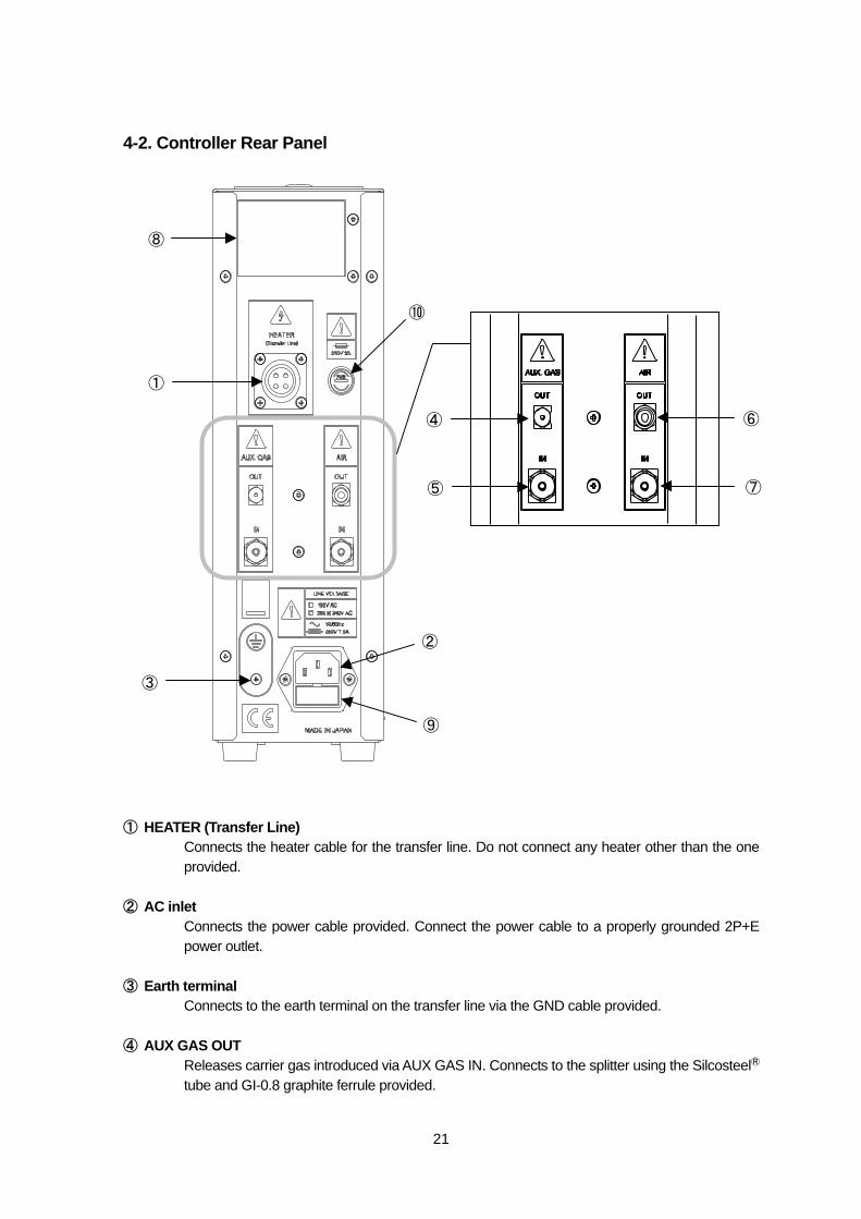
4-2. Controller Rear Panel ① HEATER (Transfer Line)
Connects the heater cable for the transfer line. Do not connect any heater other than the one provided.
② AC inlet
Connects the power cable provided. Connect the power cable to a properly grounded 2P+E power outlet.
③ Earth terminal
Connects to the earth terminal on the transfer line via the GND cable provided. ④ AUX GAS OUT
Releases carrier gas introduced via AUX GAS IN. Connects to the splitter using the SilcosteelⓇ
tube and GI-0.8 graphite ferrule provided.
⑧
①
③
②
⑨
⑥
⑦
④
⑤
⑩
22
⑤ AUX GAS IN Pipe connection for the AUX GAS supplied to the splitter. Connect a branch carrier gas pipe from the gas chromatograph primary supply pipe or other. Use a 1/8 inch tube (supplied by the user).
⑥ AIR OUT
Releases humidified air produced in the bubbling bottle. Use the PFA tube provided to connect to the transfer line humidified air intake.
⑦ AIR IN
Connects the clean air supply pipe used for the humidified air. Connect a branch air pipe to the gas chromatograph primary air supply pipe or other. Use a 1/8 inch tube (supplied by the user).
⑧ Compliance plate
Shows the serial number and date of manufacture. ⑨ Fuse cartridge
Contains the main power fuse (1 main fuse, 1 spare fuse). The rating for the main power fuse is 250V 5A 5.2×20mm.
⑩ Fuse holder
Contains the fuse for the transfer line heater. The rating for the heater line fuse is 250V 3A 5.2×20mm.
23
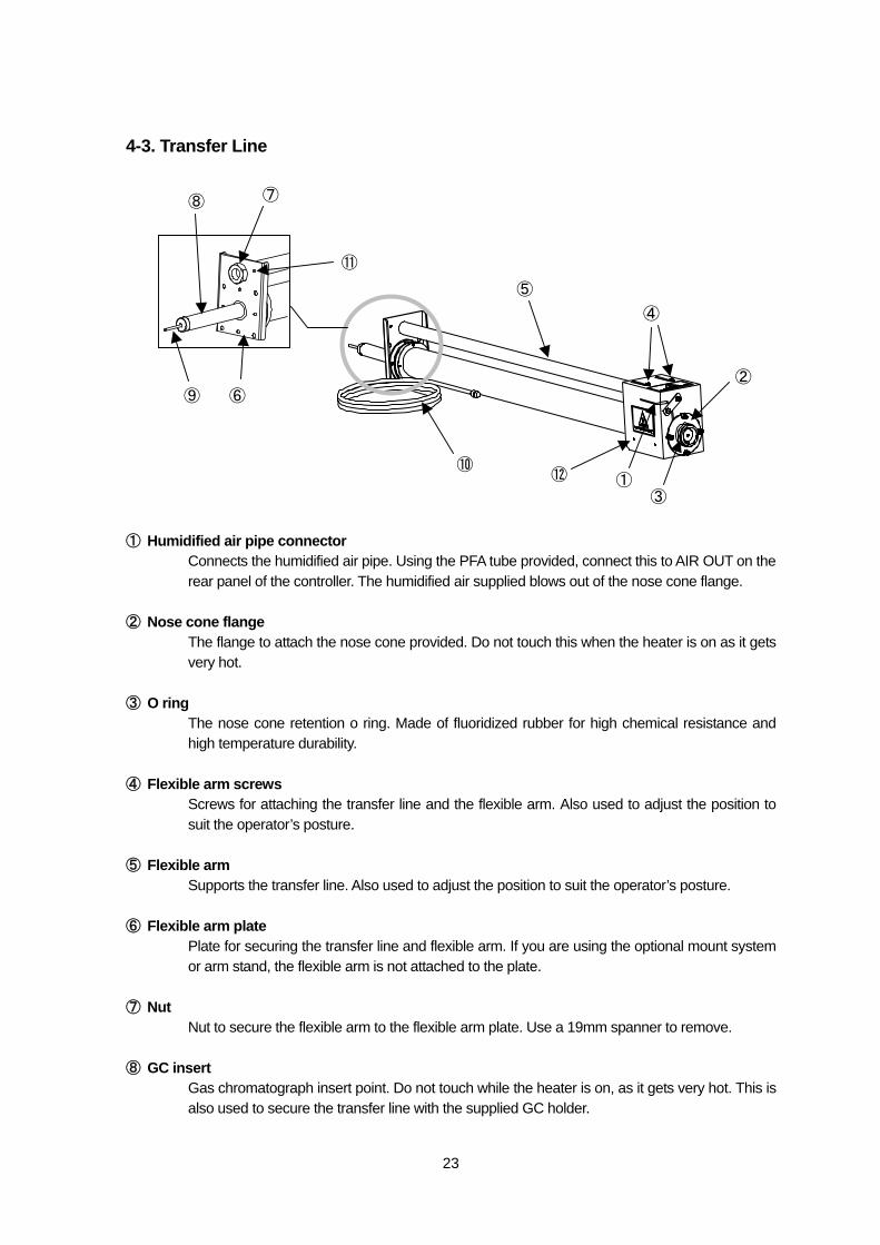
4-3. Transfer Line ① Humidified air pipe connector
Connects the humidified air pipe. Using the PFA tube provided, connect this to AIR OUT on the rear panel of the controller. The humidified air supplied blows out of the nose cone flange.
② Nose cone flange
The flange to attach the nose cone provided. Do not touch this when the heater is on as it gets very hot.
③ O ring
The nose cone retention o ring. Made of fluoridized rubber for high chemical resistance and high temperature durability.
④ Flexible arm screws
Screws for attaching the transfer line and the flexible arm. Also used to adjust the position to suit the operator’s posture.
⑤ Flexible arm
Supports the transfer line. Also used to adjust the position to suit the operator’s posture. ⑥ Flexible arm plate
Plate for securing the transfer line and flexible arm. If you are using the optional mount system or arm stand, the flexible arm is not attached to the plate.
⑦ Nut
Nut to secure the flexible arm to the flexible arm plate. Use a 19mm spanner to remove. ⑧ GC insert
Gas chromatograph insert point. Do not touch while the heater is on, as it gets very hot. This is also used to secure the transfer line with the supplied GC holder.
⑨ ⑥
⑧ ⑦
⑪ ⑤
⑩⑫ ①
②
③
④
24
⑨ Transfer line tube insert point The insert point for the transfer line capillary tube that branches from the splitter. The internal diameter is 1mm.
⑩ Heater cable
Connects to the HEATER connector on the rear panel of the controller. ⑪ Earth terminal
Connects to the earth terminal on the rear panel via the GND cable provided. ⑫ Protective cover
Cover to protect the end of the transfer line. Do not touch while the heater is on, as it gets very hot. You can also attach resin side covers.
25
5. Attaching the Transfer Line
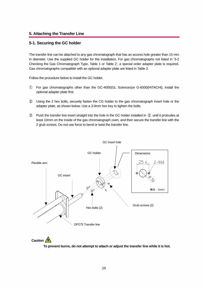
5-1. Securing the GC holder The transfer line can be attached to any gas chromatograph that has an access hole greater than 15 mm in diameter. Use the supplied GC holder for the installation. For gas chromatographs not listed in ‘3-2 Checking the Gas Chromatograph Type, Table 1 or Table 2’, a special order adapter plate is required. Gas chromatographs compatible with an optional adapter plate are listed in Table 2. Follow the procedure below to install the GC holder. ① For gas chromatographs other than the GC-4000(GL Sciences)or G-6000(HITACHI), install the
optional adapter plate first. ② Using the 2 hex bolts, securely fasten the CG holder to the gas chromatograph insert hole or the
adapter plate, as shown below. Use a 3.0mm hex key to tighten the bolts. ③ Push the transfer line insert straight into the hole in the GC holder installed in ② until it protrudes at
least 10mm on the inside of the gas chromatograph oven, and then secure the transfer line with the 2 grub screws. Do not use force to bend or twist the transfer line.
To prevent burns, do not attempt to attach or adjust the transfer line while it is hot.
Grub screws (2)
Dimensions
Hex bolts (2)
GC holder
OP275 Transfer line
単位:[mm]
GC insert
Flexible arm
GC insert hole
Caution
26
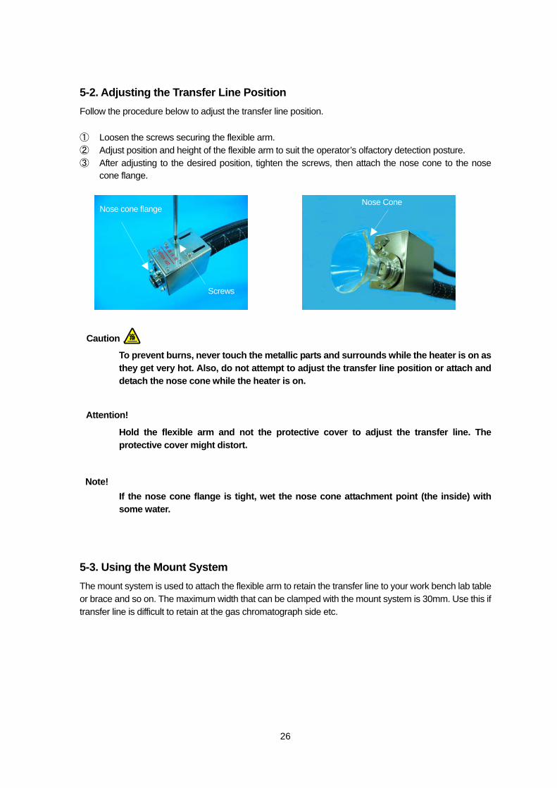
5-2. Adjusting the Transfer Line Position Follow the procedure below to adjust the transfer line position. ① Loosen the screws securing the flexible arm. ② Adjust position and height of the flexible arm to suit the operator’s olfactory detection posture. ③ After adjusting to the desired position, tighten the screws, then attach the nose cone to the nose
cone flange.
To prevent burns, never touch the metallic parts and surrounds while the heater is on as they get very hot. Also, do not attempt to adjust the transfer line position or attach and detach the nose cone while the heater is on.
Hold the flexible arm and not the protective cover to adjust the transfer line. The protective cover might distort.
If the nose cone flange is tight, wet the nose cone attachment point (the inside) with some water.
5-3. Using the Mount System The mount system is used to attach the flexible arm to retain the transfer line to your work bench lab table or brace and so on. The maximum width that can be clamped with the mount system is 30mm. Use this if transfer line is difficult to retain at the gas chromatograph side etc.
Screws
Nose cone flange Nose Cone
Caution
Attention!
Note!
27
A
Knob
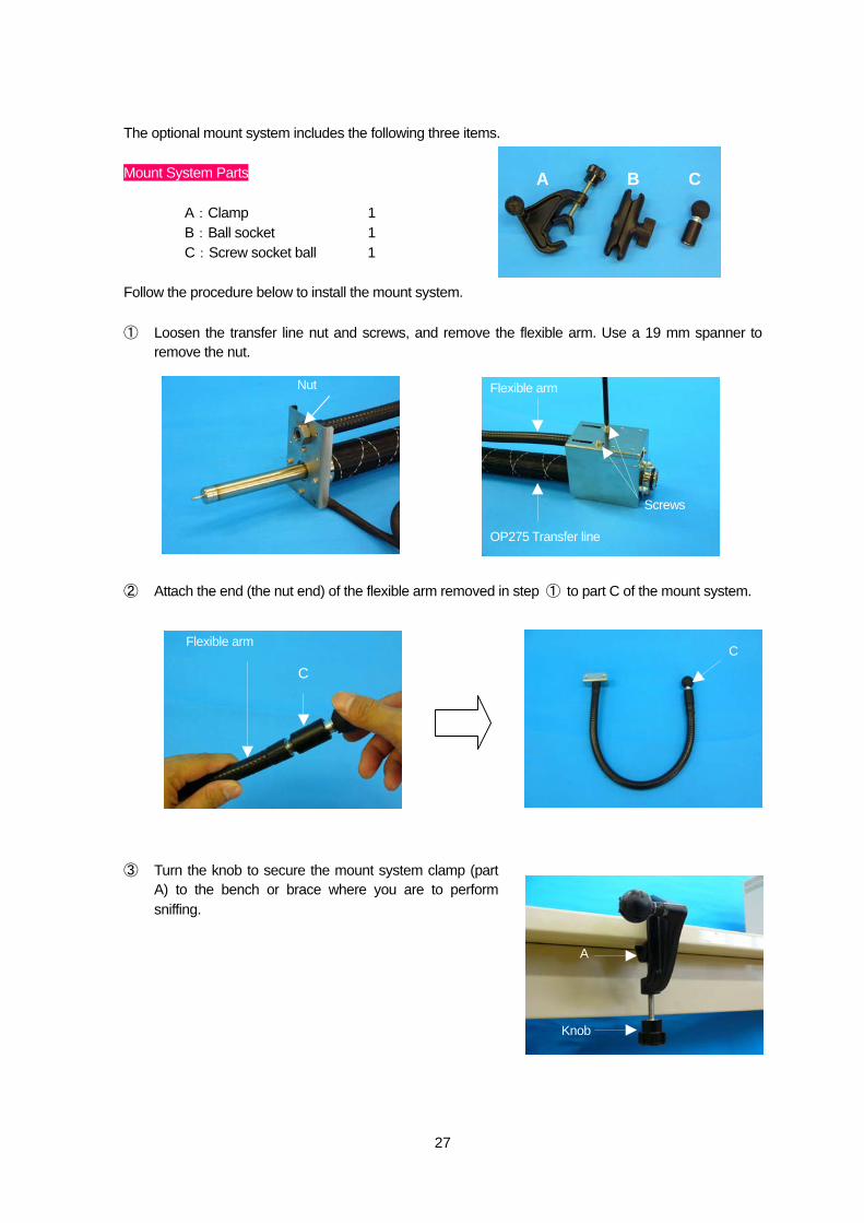
The optional mount system includes the following three items. Mount System Parts
A:Clamp 1 B:Ball socket 1 C:Screw socket ball 1
Follow the procedure below to install the mount system. ① Loosen the transfer line nut and screws, and remove the flexible arm. Use a 19 mm spanner to
remove the nut. ② Attach the end (the nut end) of the flexible arm removed in step ① to part C of the mount system. ③ Turn the knob to secure the mount system clamp (part
A) to the bench or brace where you are to perform sniffing.
A B C
Flexible arm
OP275 Transfer line
Screws
Nut
C
Flexible arm C
28
Screw Stabilizer
B A
C
Knob
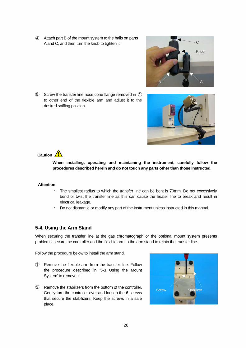
④ Attach part B of the mount system to the balls on parts A and C, and then turn the knob to tighten it.
⑤ Screw the transfer line nose cone flange removed in ①
to other end of the flexible arm and adjust it to the desired sniffing position.
When installing, operating and maintaining the instrument, carefully follow the procedures described herein and do not touch any parts other than those instructed.
・ The smallest radius to which the transfer line can be bent is 70mm. Do not excessively bend or twist the transfer line as this can cause the heater line to break and result in electrical leakage.
・ Do not dismantle or modify any part of the instrument unless instructed in this manual.
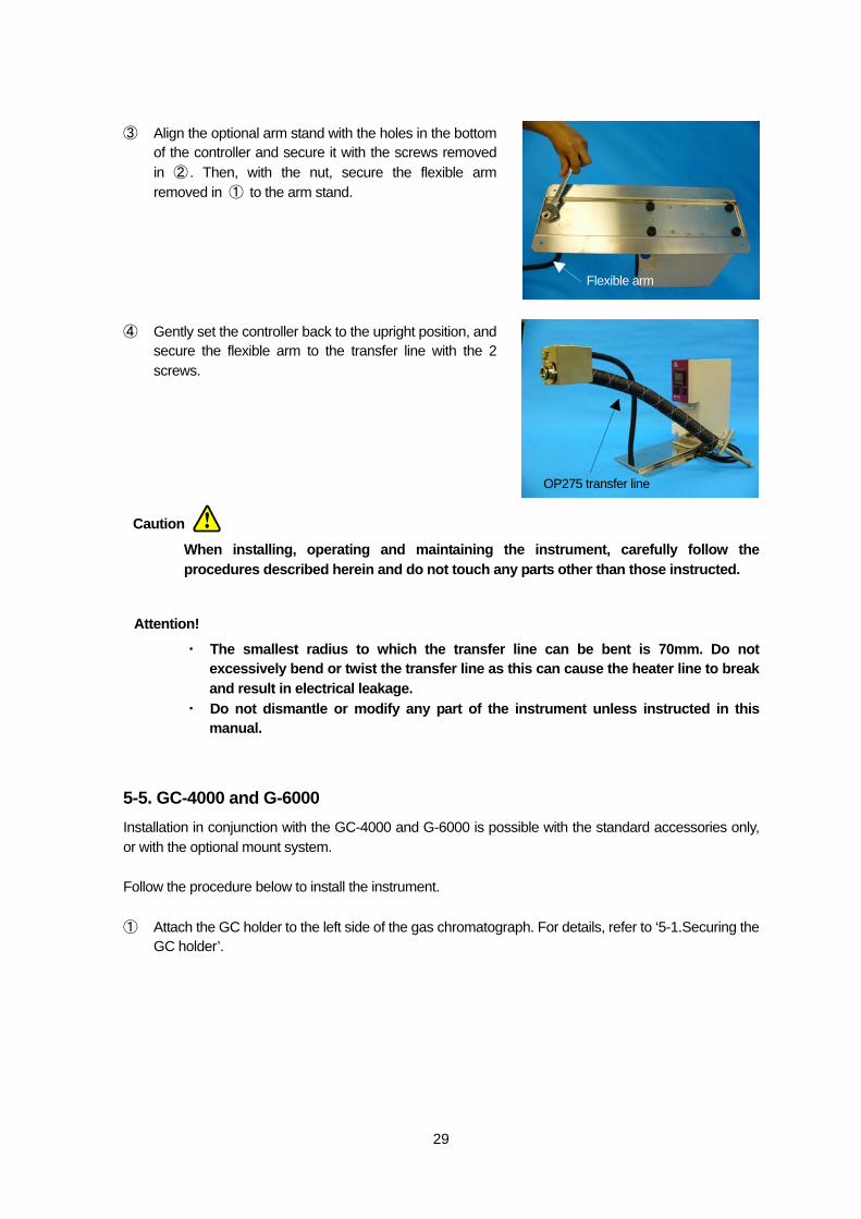
5-4. Using the Arm Stand When securing the transfer line at the gas chromatograph or the optional mount system presents problems, secure the controller and the flexible arm to the arm stand to retain the transfer line. Follow the procedure below to install the arm stand. ① Remove the flexible arm from the transfer line. Follow
the procedure described in ‘5-3 Using the Mount System’ to remove it.
② Remove the stabilizers from the bottom of the controller.
Gently turn the controller over and loosen the 6 screws that secure the stabilizers. Keep the screws in a safe place.
Caution
Attention!
29
Flexible arm
OP275 transfer line
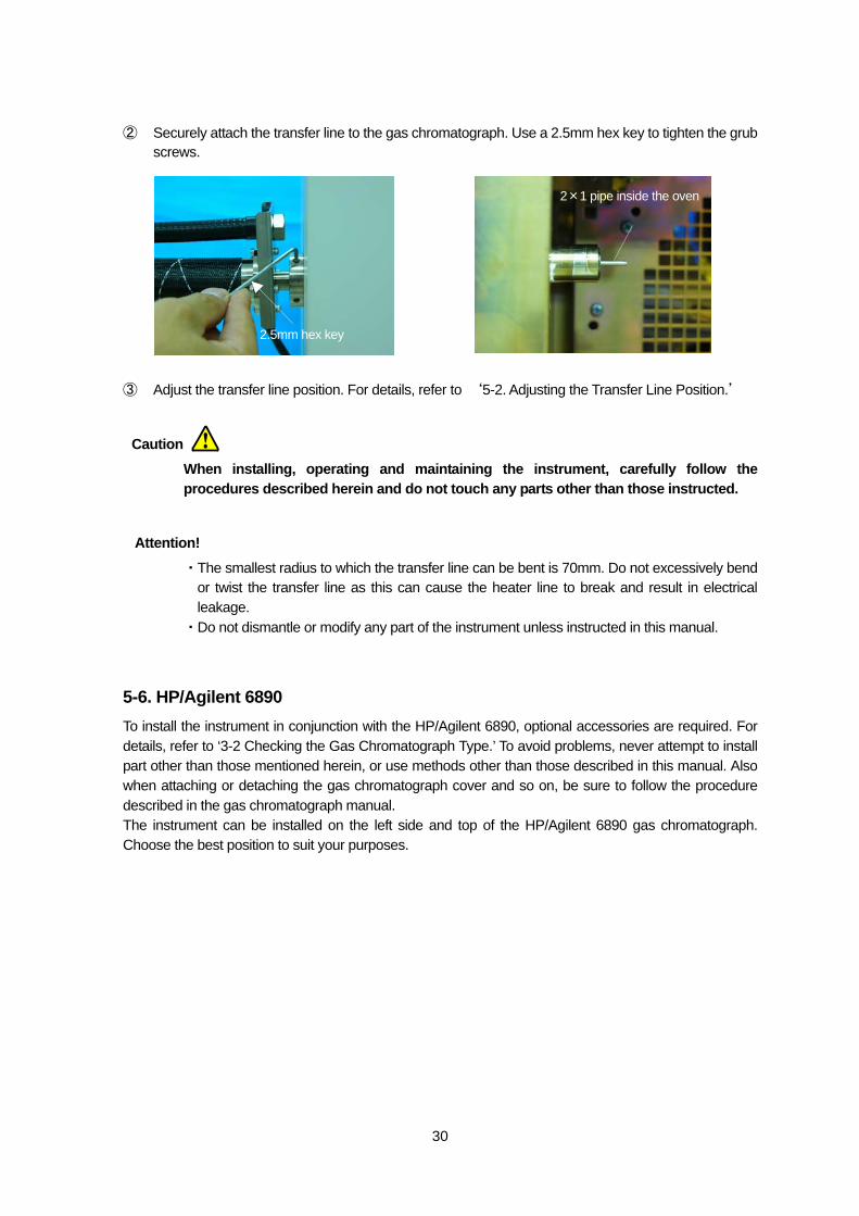
③ Align the optional arm stand with the holes in the bottom of the controller and secure it with the screws removed in ② . Then, with the nut, secure the flexible arm removed in ① to the arm stand.
④ Gently set the controller back to the upright position, and
secure the flexible arm to the transfer line with the 2 screws.
When installing, operating and maintaining the instrument, carefully follow the procedures described herein and do not touch any parts other than those instructed.
・ The smallest radius to which the transfer line can be bent is 70mm. Do not excessively bend or twist the transfer line as this can cause the heater line to break and result in electrical leakage.
・ Do not dismantle or modify any part of the instrument unless instructed in this manual.
5-5. GC-4000 and G-6000 Installation in conjunction with the GC-4000 and G-6000 is possible with the standard accessories only, or with the optional mount system. Follow the procedure below to install the instrument. ① Attach the GC holder to the left side of the gas chromatograph. For details, refer to ‘5-1.Securing the
GC holder’.
Caution
Attention!
30
② Securely attach the transfer line to the gas chromatograph. Use a 2.5mm hex key to tighten the grub screws.
③ Adjust the transfer line position. For details, refer to ‘5-2. Adjusting the Transfer Line Position.’
When installing, operating and maintaining the instrument, carefully follow the procedures described herein and do not touch any parts other than those instructed.
・The smallest radius to which the transfer line can be bent is 70mm. Do not excessively bend or twist the transfer line as this can cause the heater line to break and result in electrical leakage.
・Do not dismantle or modify any part of the instrument unless instructed in this manual.
5-6. HP/Agilent 6890 To install the instrument in conjunction with the HP/Agilent 6890, optional accessories are required. For details, refer to ‘3-2 Checking the Gas Chromatograph Type.’ To avoid problems, never attempt to install part other than those mentioned herein, or use methods other than those described in this manual. Also when attaching or detaching the gas chromatograph cover and so on, be sure to follow the procedure described in the gas chromatograph manual. The instrument can be installed on the left side and top of the HP/Agilent 6890 gas chromatograph. Choose the best position to suit your purposes.
2.5mm hex key
2×1 pipe inside the oven
Caution
Attention!
31
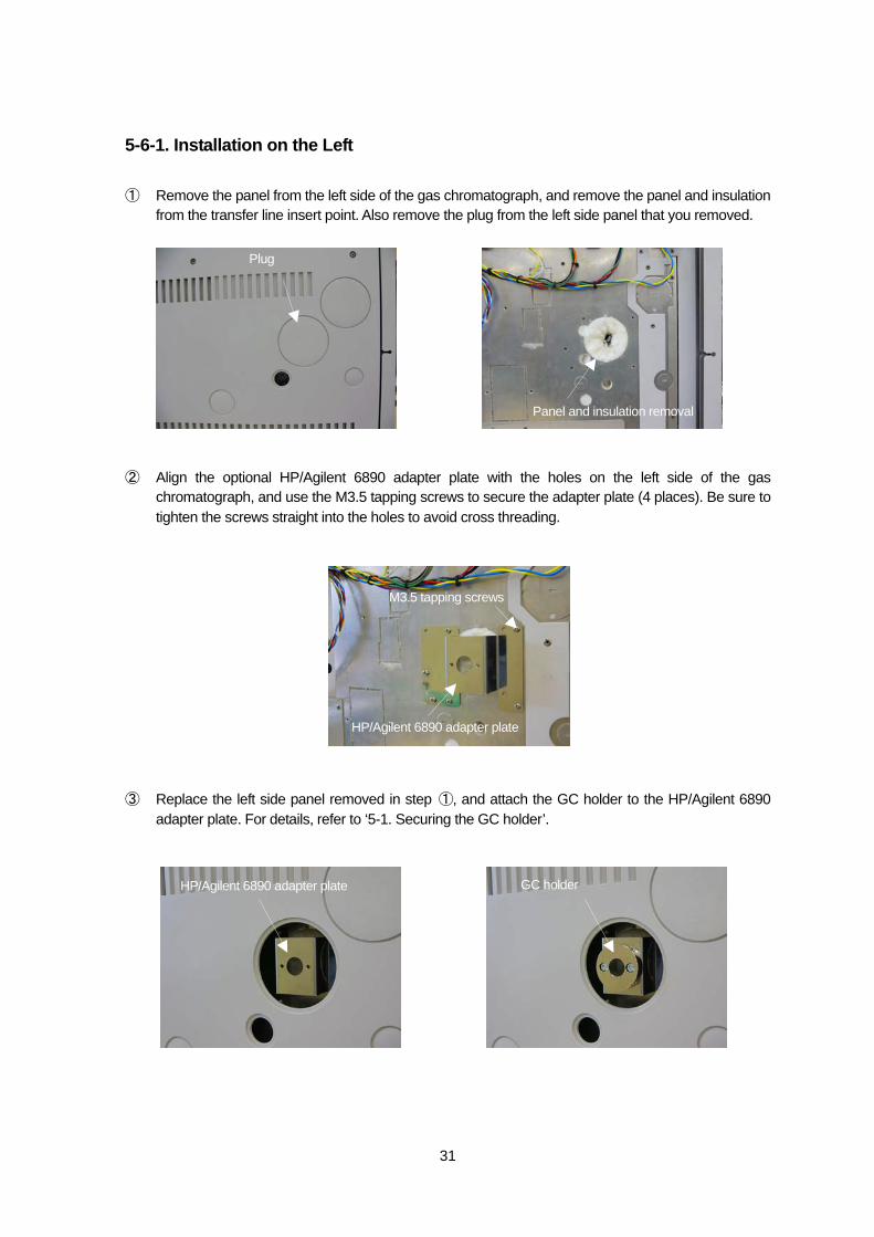
5-6-1. Installation on the Left ① Remove the panel from the left side of the gas chromatograph, and remove the panel and insulation
from the transfer line insert point. Also remove the plug from the left side panel that you removed. ② Align the optional HP/Agilent 6890 adapter plate with the holes on the left side of the gas
chromatograph, and use the M3.5 tapping screws to secure the adapter plate (4 places). Be sure to tighten the screws straight into the holes to avoid cross threading.
③ Replace the left side panel removed in step ①, and attach the GC holder to the HP/Agilent 6890
adapter plate. For details, refer to ‘5-1. Securing the GC holder’.
Plug
Panel and insulation removal
HP/Agilent 6890 adapter plate
M3.5 tapping screws
HP/Agilent 6890 adapter plate GC holder
32
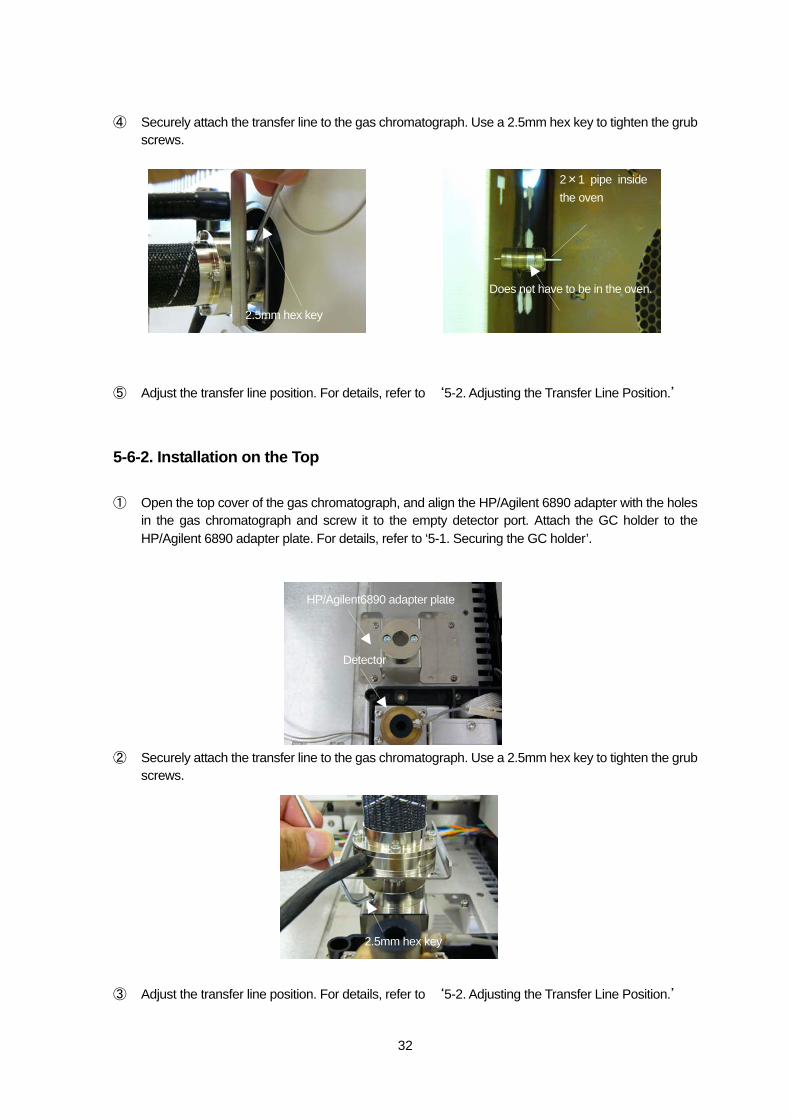
④ Securely attach the transfer line to the gas chromatograph. Use a 2.5mm hex key to tighten the grub screws.
⑤ Adjust the transfer line position. For details, refer to ‘5-2. Adjusting the Transfer Line Position.’
5-6-2. Installation on the Top ① Open the top cover of the gas chromatograph, and align the HP/Agilent 6890 adapter with the holes
in the gas chromatograph and screw it to the empty detector port. Attach the GC holder to the HP/Agilent 6890 adapter plate. For details, refer to ‘5-1. Securing the GC holder’.
② Securely attach the transfer line to the gas chromatograph. Use a 2.5mm hex key to tighten the grub
screws. ③ Adjust the transfer line position. For details, refer to ‘5-2. Adjusting the Transfer Line Position.’
Detector
HP/Agilent6890 adapter plate
2.5mm hex key
2.5mm hex key
2×1 pipe insidethe oven
Does not have to be in the oven.
33
When installing, operating and maintaining the instrument, carefully follow the procedures described herein and do not touch any parts other than those instructed.
・ The smallest radius to which the transfer line can be bent is 70mm. Do not excessively bend or twist the transfer line as this can cause the heater line to break and result in electrical leakage.
・ Do not dismantle or modify any part of the instrument unless instructed in this manual.
5-7. Shimadzu GC-2010 To install the instrument in conjunction with Shimadzu GC-2010 options other than the standard accessories are required. For details, refer to ‘3-2 Checking the Gas Chromatograph Type.’ To avoid problems, never attempt to install part other than those mentioned herein, or use methods other than those described in this manual. Also when attaching or detaching the gas chromatograph cover and so on, be sure to follow the procedure described in the gas chromatograph manual. The instrument can be installed onto the Shimadzu GC-2010 left or right sides. If there are no restrictions, we recommend installation onto the left side. ① First, attach the standard accessories arm stand to the controller and transfer line. For details, refer
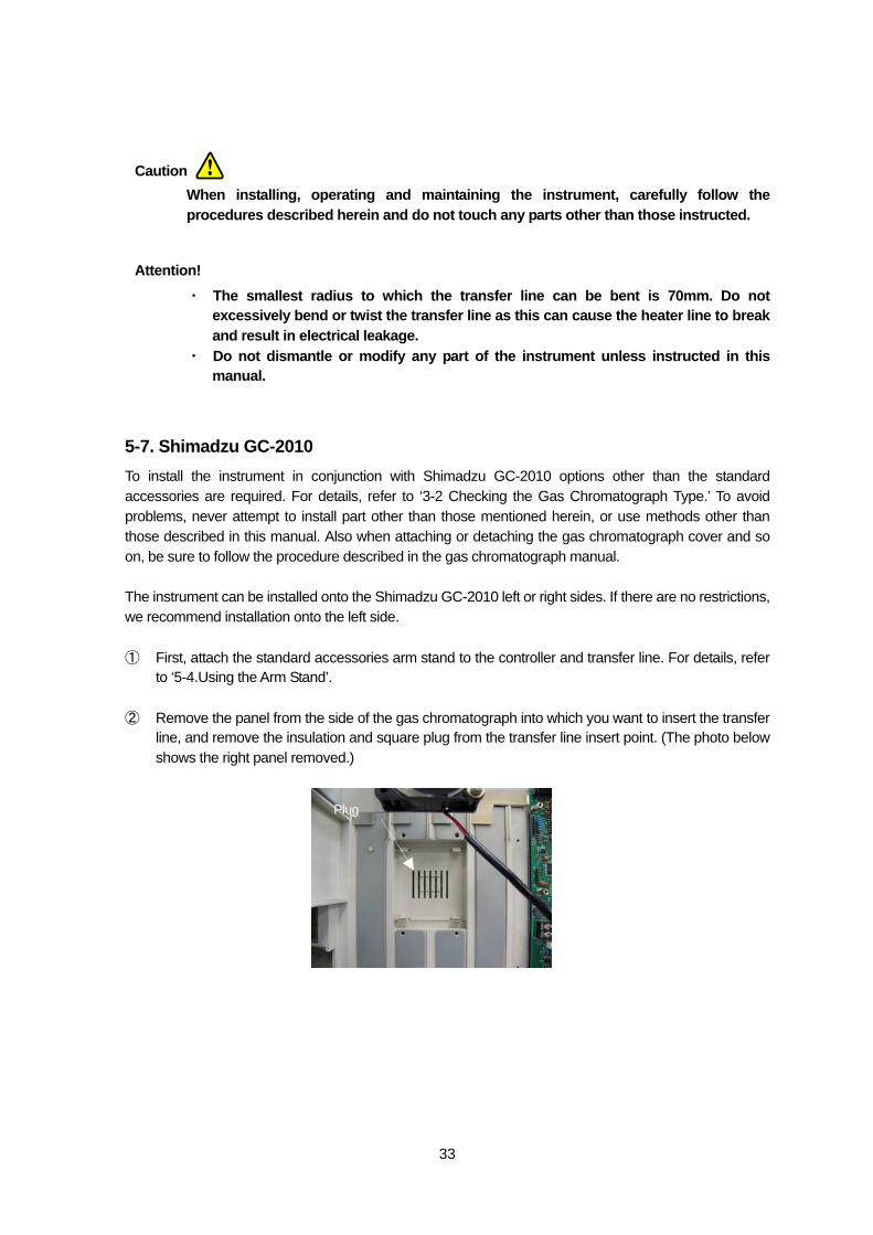
to ‘5-4.Using the Arm Stand’. ② Remove the panel from the side of the gas chromatograph into which you want to insert the transfer
line, and remove the insulation and square plug from the transfer line insert point. (The photo below shows the right panel removed.)
Plug
Caution
Attention!
34
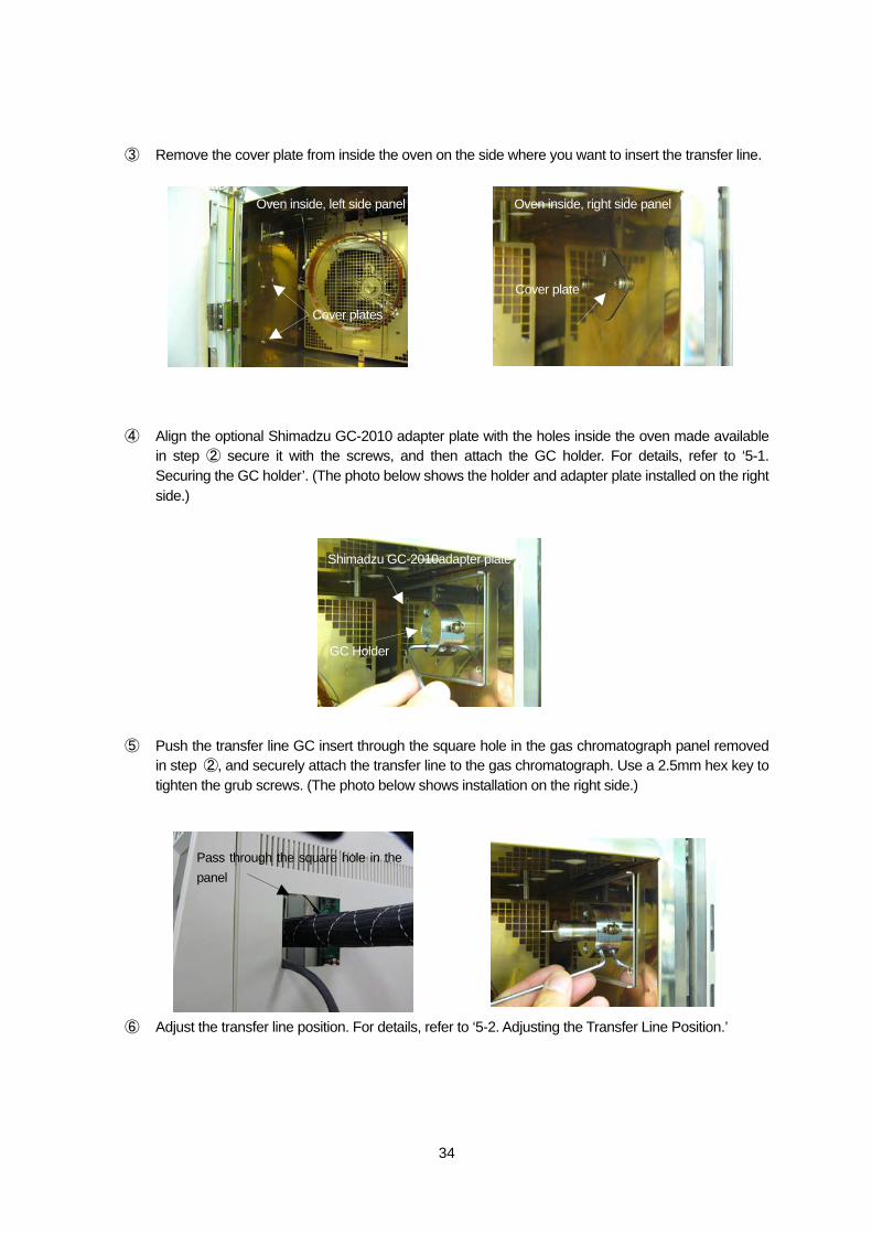
③ Remove the cover plate from inside the oven on the side where you want to insert the transfer line. ④ Align the optional Shimadzu GC-2010 adapter plate with the holes inside the oven made available
in step ② secure it with the screws, and then attach the GC holder. For details, refer to ‘5-1. Securing the GC holder’. (The photo below shows the holder and adapter plate installed on the right side.)
⑤ Push the transfer line GC insert through the square hole in the gas chromatograph panel removed
in step ②, and securely attach the transfer line to the gas chromatograph. Use a 2.5mm hex key to tighten the grub screws. (The photo below shows installation on the right side.)
⑥ Adjust the transfer line position. For details, refer to ‘5-2. Adjusting the Transfer Line Position.’
Cover plate
Oven inside, right side panel Oven inside, left side panel
Cover plates
Shimadzu GC-2010adapter plate
GC Holder
Pass through the square hole in thepanel
35
When installing, operating and maintaining the instrument, carefully follow the procedures described herein and do not touch any parts other than those instructed.
To prevent burns, do not attempt to attach or adjust the transfer line while it is hot.
・ The smallest radius to which the transfer line can be bent is 70mm. Do not excessively bend or twist the transfer line as this can cause the heater line to break and result in electrical leakage.
・ Do not dismantle or modify any part of the instrument unless instructed in this manual.
You can also use the optional mount system with the Shimadzu GC-2010 as well as the arm stand.
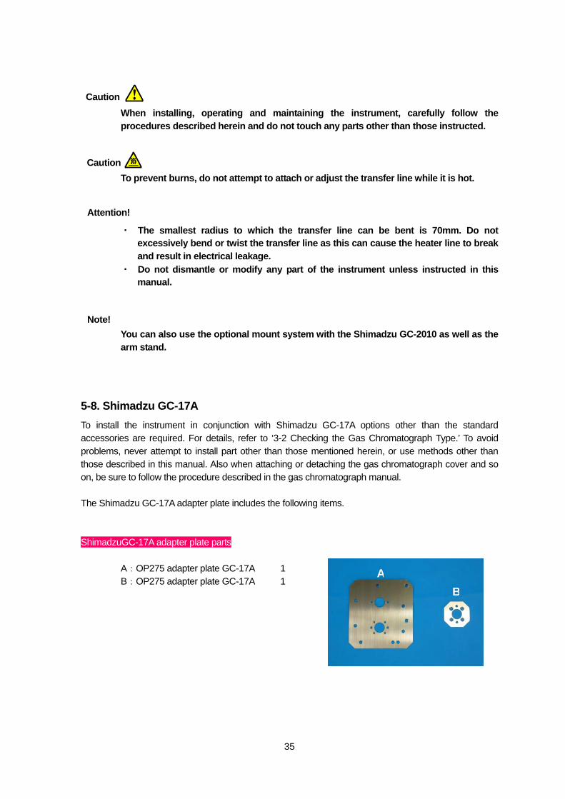
5-8. Shimadzu GC-17A To install the instrument in conjunction with Shimadzu GC-17A options other than the standard accessories are required. For details, refer to ‘3-2 Checking the Gas Chromatograph Type.’ To avoid problems, never attempt to install part other than those mentioned herein, or use methods other than those described in this manual. Also when attaching or detaching the gas chromatograph cover and so on, be sure to follow the procedure described in the gas chromatograph manual. The Shimadzu GC-17A adapter plate includes the following items. ShimadzuGC-17A adapter plate parts
A:OP275 adapter plate GC-17A 1 B:OP275 adapter plate GC-17A 1
AB
Caution
Caution
Attention!
Note!
36
GC holder
OP275 Transfer line
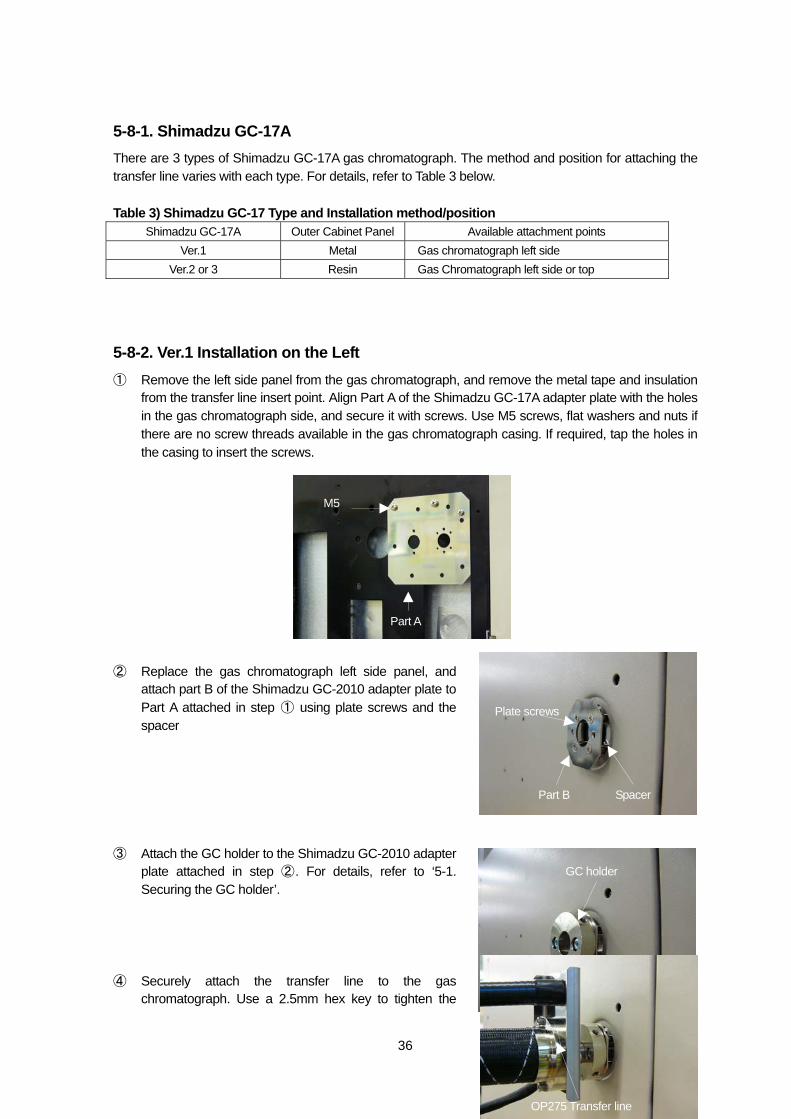
5-8-1. Shimadzu GC-17A There are 3 types of Shimadzu GC-17A gas chromatograph. The method and position for attaching the transfer line varies with each type. For details, refer to Table 3 below. Table 3) Shimadzu GC-17 Type and Installation method/position
Shimadzu GC-17A Outer Cabinet Panel Available attachment points Ver.1 Metal Gas chromatograph left side
Ver.2 or 3 Resin Gas Chromatograph left side or top
5-8-2. Ver.1 Installation on the Left ① Remove the left side panel from the gas chromatograph, and remove the metal tape and insulation
from the transfer line insert point. Align Part A of the Shimadzu GC-17A adapter plate with the holes in the gas chromatograph side, and secure it with screws. Use M5 screws, flat washers and nuts if there are no screw threads available in the gas chromatograph casing. If required, tap the holes in the casing to insert the screws.
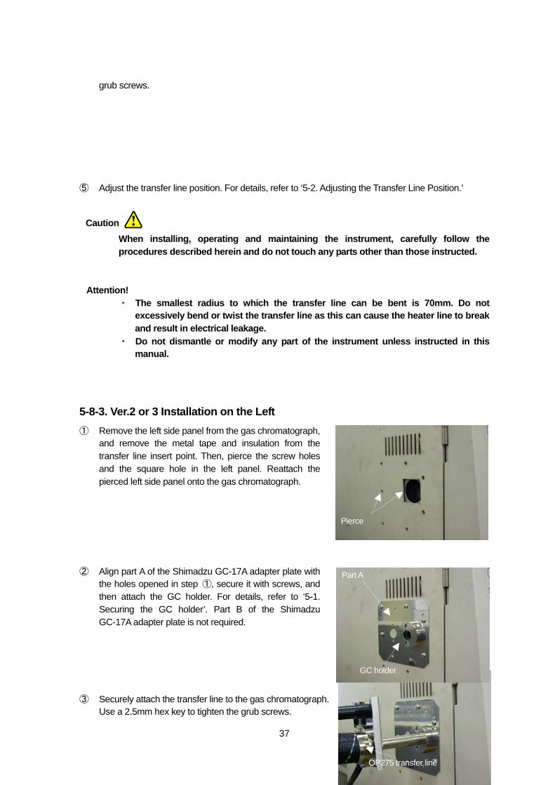
② Replace the gas chromatograph left side panel, and
attach part B of the Shimadzu GC-2010 adapter plate to Part A attached in step ① using plate screws and the spacer
③ Attach the GC holder to the Shimadzu GC-2010 adapter
plate attached in step ②. For details, refer to ‘5-1. Securing the GC holder’.
④ Securely attach the transfer line to the gas
chromatograph. Use a 2.5mm hex key to tighten the
Part A
M5
Part B Spacer
Plate screws
37
OP275 transfer line
grub screws. ⑤ Adjust the transfer line position. For details, refer to ‘5-2. Adjusting the Transfer Line Position.’
When installing, operating and maintaining the instrument, carefully follow the procedures described herein and do not touch any parts other than those instructed.
・ The smallest radius to which the transfer line can be bent is 70mm. Do not excessively bend or twist the transfer line as this can cause the heater line to break and result in electrical leakage.
・ Do not dismantle or modify any part of the instrument unless instructed in this manual.
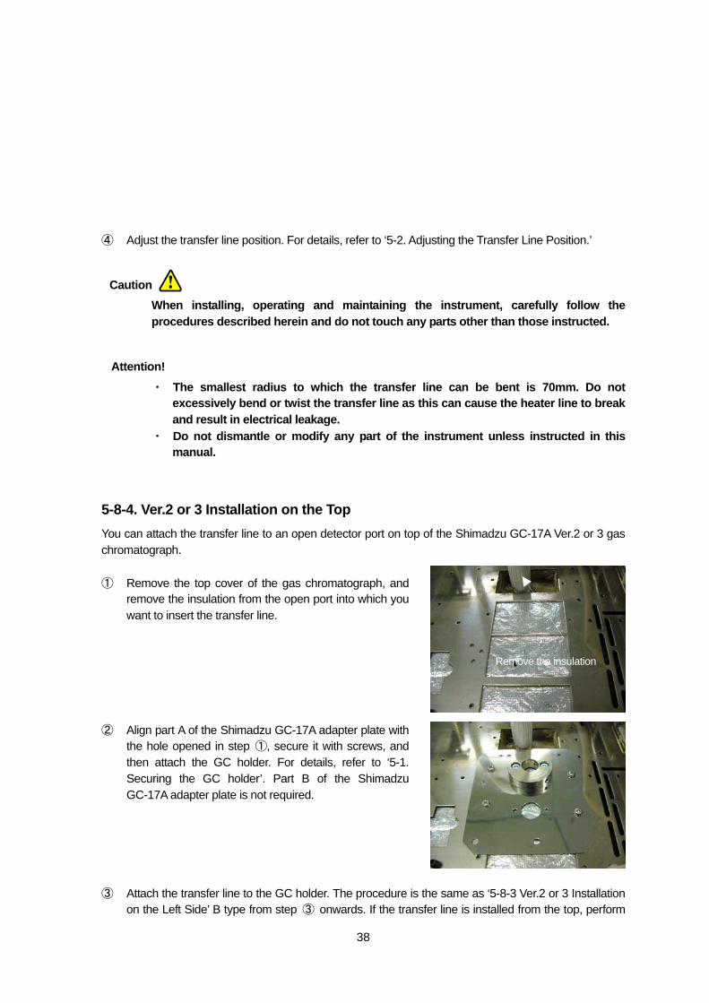
5-8-3. Ver.2 or 3 Installation on the Left ① Remove the left side panel from the gas chromatograph,
and remove the metal tape and insulation from the transfer line insert point. Then, pierce the screw holes and the square hole in the left panel. Reattach the pierced left side panel onto the gas chromatograph.
② Align part A of the Shimadzu GC-17A adapter plate with
the holes opened in step ①, secure it with screws, and then attach the GC holder. For details, refer to ‘5-1. Securing the GC holder’. Part B of the Shimadzu GC-17A adapter plate is not required.
③ Securely attach the transfer line to the gas chromatograph.
Use a 2.5mm hex key to tighten the grub screws.
Pierce
Part A
GC holder
Caution
Attention!
38
④ Adjust the transfer line position. For details, refer to ‘5-2. Adjusting the Transfer Line Position.’
When installing, operating and maintaining the instrument, carefully follow the procedures described herein and do not touch any parts other than those instructed.
・ The smallest radius to which the transfer line can be bent is 70mm. Do not excessively bend or twist the transfer line as this can cause the heater line to break and result in electrical leakage.
・ Do not dismantle or modify any part of the instrument unless instructed in this manual.
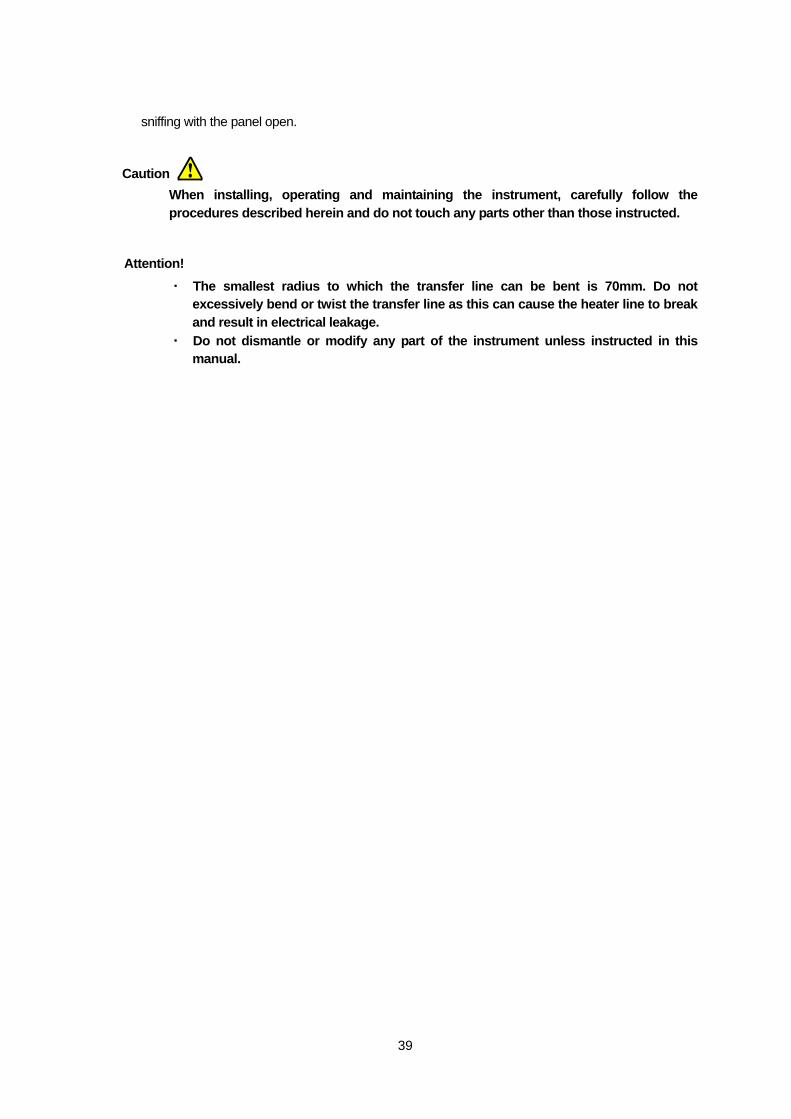
5-8-4. Ver.2 or 3 Installation on the Top You can attach the transfer line to an open detector port on top of the Shimadzu GC-17A Ver.2 or 3 gas chromatograph. ① Remove the top cover of the gas chromatograph, and
remove the insulation from the open port into which you want to insert the transfer line.
② Align part A of the Shimadzu GC-17A adapter plate with
the hole opened in step ①, secure it with screws, and then attach the GC holder. For details, refer to ‘5-1. Securing the GC holder’. Part B of the Shimadzu GC-17A adapter plate is not required.
③ Attach the transfer line to the GC holder. The procedure is the same as ‘5-8-3 Ver.2 or 3 Installation
on the Left Side’ B type from step ③ onwards. If the transfer line is installed from the top, perform
Remove the insulation
Caution
Attention!
39
sniffing with the panel open.
When installing, operating and maintaining the instrument, carefully follow the procedures described herein and do not touch any parts other than those instructed.
・ The smallest radius to which the transfer line can be bent is 70mm. Do not excessively bend or twist the transfer line as this can cause the heater line to break and result in electrical leakage.
・ Do not dismantle or modify any part of the instrument unless instructed in this manual.
Caution
Attention!
40
6. Splitter Connection The splitter mixes samples separated in the column with AUX GAS, and splits the flow to the transfer line and the gas chromatograph detector. The splitter is inactively treated, enabling minimization of sample condensation and absorption in the line.
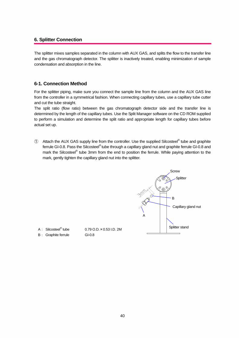
6-1. Connection Method For the splitter piping, make sure you connect the sample line from the column and the AUX GAS line from the controller in a symmetrical fashion. When connecting capillary tubes, use a capillary tube cutter and cut the tube straight. The split ratio (flow ratio) between the gas chromatograph detector side and the transfer line is determined by the length of the capillary tubes. Use the Split Manager software on the CD ROM supplied to perform a simulation and determine the split ratio and appropriate length for capillary tubes before actual set up. ① Attach the AUX GAS supply line from the controller. Use the supplied Silcosteel® tube and graphite
ferrule GI-0.8. Pass the Silcosteel® tube through a capillary gland nut and graphite ferrule GI-0.8 and mark the Silcosteel® tube 3mm from the end to position the ferrule. While paying attention to the mark, gently tighten the capillary gland nut into the splitter.
A: Silcosteel® tube 0.79 O.D.×0.53 I.D. 2M B: Graphite ferrule GI-0.8
A
B
Splitter stand
Capillary gland nut
Splitter
Screw
41
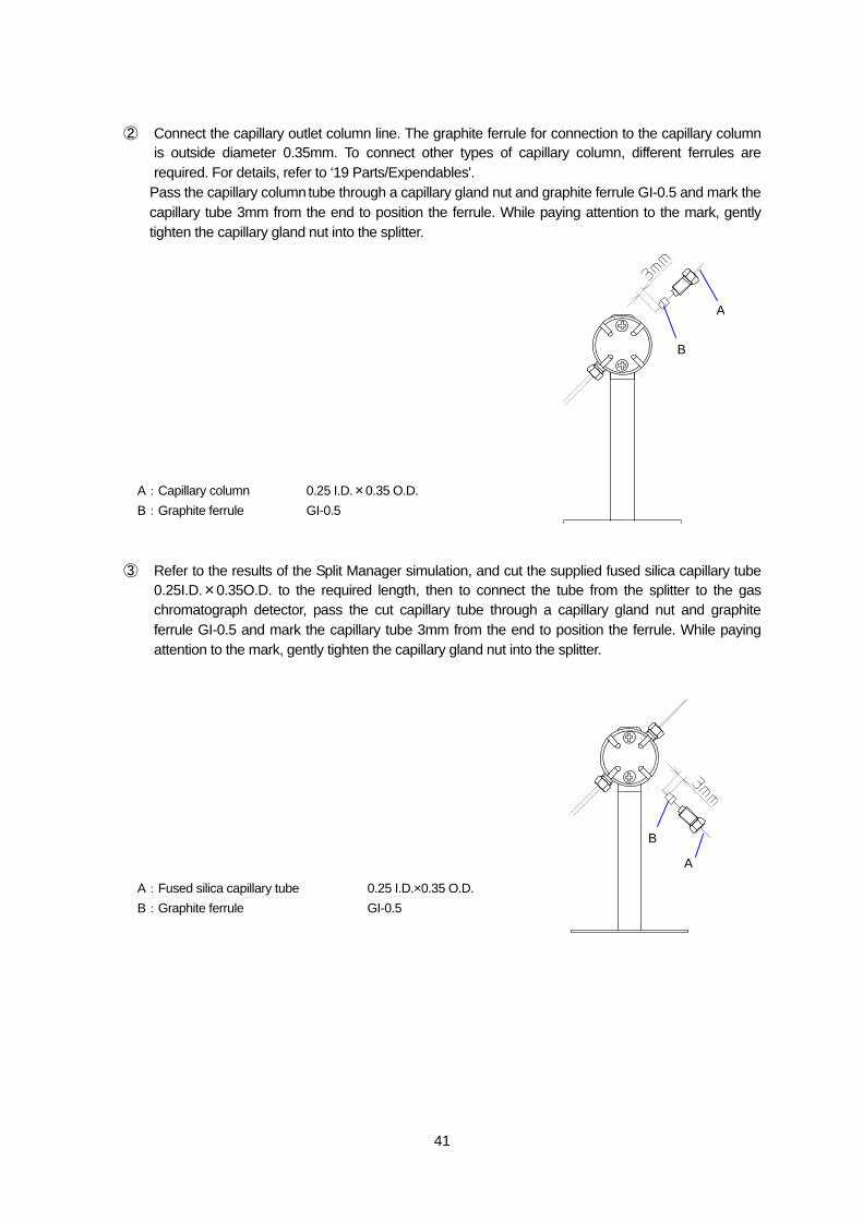
② Connect the capillary outlet column line. The graphite ferrule for connection to the capillary column is outside diameter 0.35mm. To connect other types of capillary column, different ferrules are required. For details, refer to ‘19 Parts/Expendables'.
Pass the capillary column tube through a capillary gland nut and graphite ferrule GI-0.5 and mark the capillary tube 3mm from the end to position the ferrule. While paying attention to the mark, gently tighten the capillary gland nut into the splitter.
A:Capillary column 0.25 I.D.×0.35 O.D. B:Graphite ferrule GI-0.5
③ Refer to the results of the Split Manager simulation, and cut the supplied fused silica capillary tube
0.25I.D.×0.35O.D. to the required length, then to connect the tube from the splitter to the gas chromatograph detector, pass the cut capillary tube through a capillary gland nut and graphite ferrule GI-0.5 and mark the capillary tube 3mm from the end to position the ferrule. While paying attention to the mark, gently tighten the capillary gland nut into the splitter.
A:Fused silica capillary tube 0.25 I.D.×0.35 O.D. B:Graphite ferrule GI-0.5
A
B
A
B
42
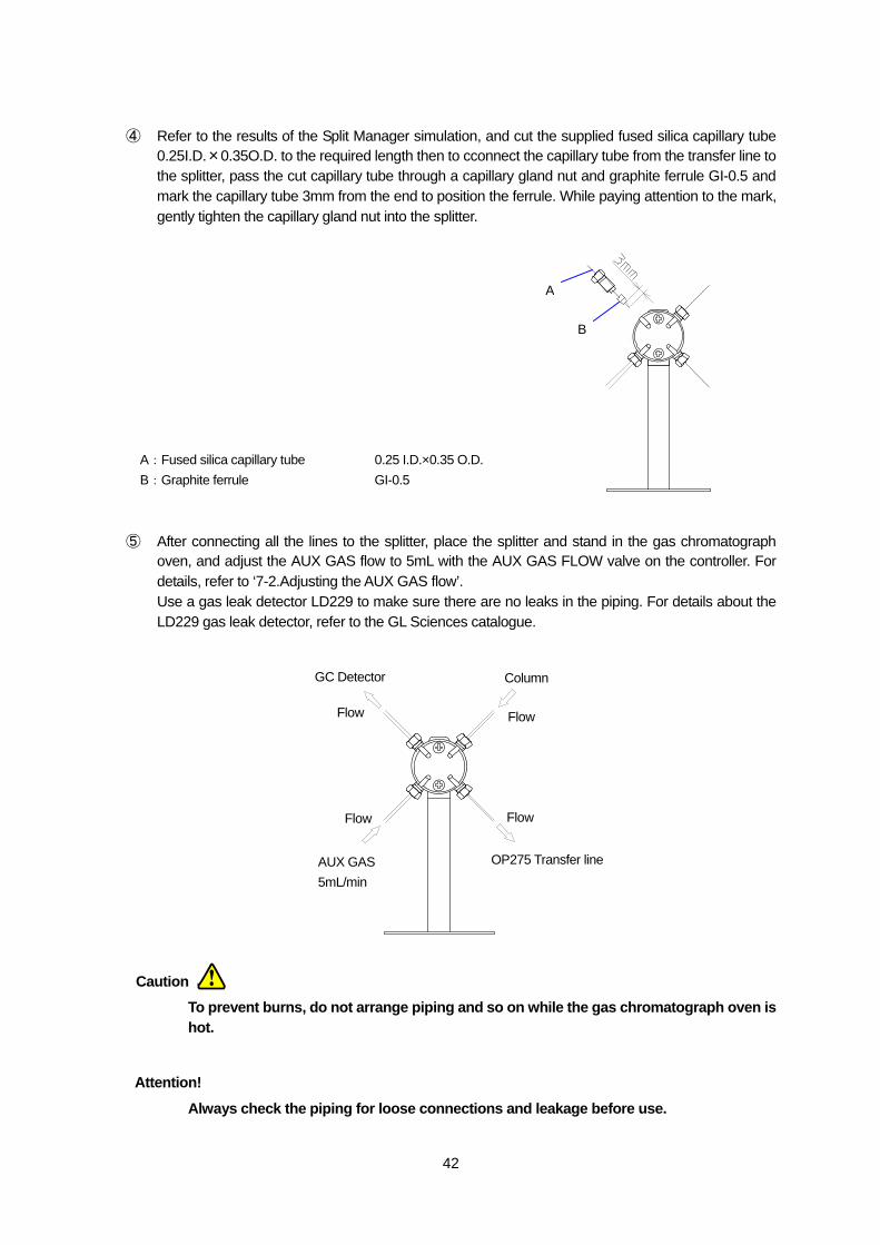
④ Refer to the results of the Split Manager simulation, and cut the supplied fused silica capillary tube 0.25I.D.×0.35O.D. to the required length then to cconnect the capillary tube from the transfer line to the splitter, pass the cut capillary tube through a capillary gland nut and graphite ferrule GI-0.5 and mark the capillary tube 3mm from the end to position the ferrule. While paying attention to the mark, gently tighten the capillary gland nut into the splitter.
A:Fused silica capillary tube 0.25 I.D.×0.35 O.D. B:Graphite ferrule GI-0.5
⑤ After connecting all the lines to the splitter, place the splitter and stand in the gas chromatograph
oven, and adjust the AUX GAS flow to 5mL with the AUX GAS FLOW valve on the controller. For details, refer to ‘7-2.Adjusting the AUX GAS flow’. Use a gas leak detector LD229 to make sure there are no leaks in the piping. For details about the LD229 gas leak detector, refer to the GL Sciences catalogue.
To prevent burns, do not arrange piping and so on while the gas chromatograph oven is hot.
Always check the piping for loose connections and leakage before use.
A
B
GC Detector
Flow
AUX GAS 5mL/min
Flow
Column
Flow
OP275 Transfer line
Flow
Caution
Attention!
43
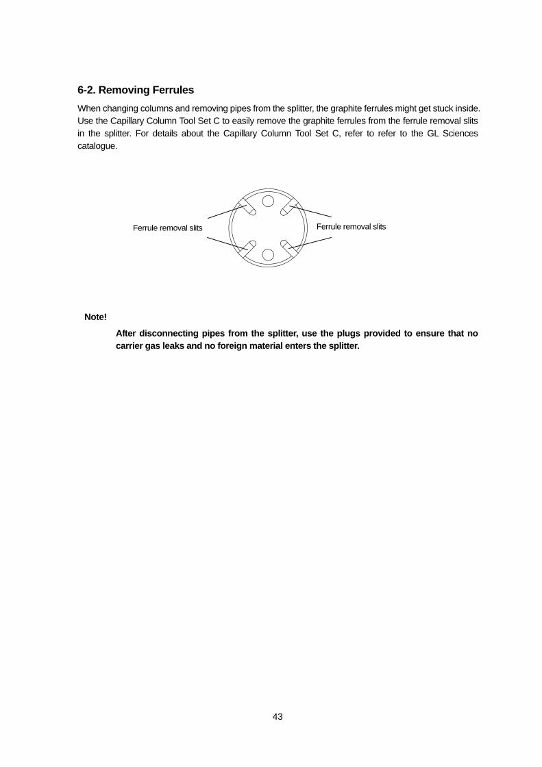
6-2. Removing Ferrules When changing columns and removing pipes from the splitter, the graphite ferrules might get stuck inside. Use the Capillary Column Tool Set C to easily remove the graphite ferrules from the ferrule removal slits in the splitter. For details about the Capillary Column Tool Set C, refer to refer to the GL Sciences catalogue.
After disconnecting pipes from the splitter, use the plugs provided to ensure that no carrier gas leaks and no foreign material enters the splitter.
Ferrule removal slits Ferrule removal slits
Note!
44
7. Preparation
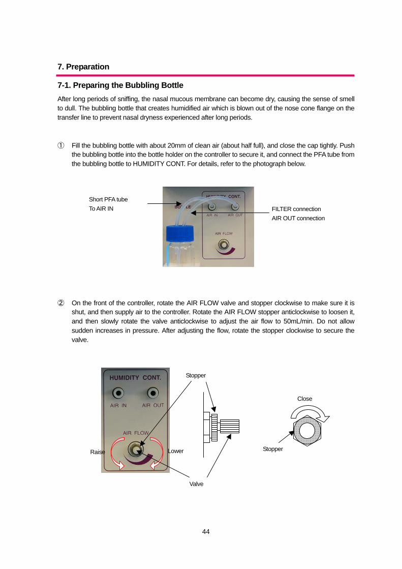
7-1. Preparing the Bubbling Bottle After long periods of sniffing, the nasal mucous membrane can become dry, causing the sense of smell to dull. The bubbling bottle that creates humidified air which is blown out of the nose cone flange on the transfer line to prevent nasal dryness experienced after long periods. ① Fill the bubbling bottle with about 20mm of clean air (about half full), and close the cap tightly. Push
the bubbling bottle into the bottle holder on the controller to secure it, and connect the PFA tube from the bubbling bottle to HUMIDITY CONT. For details, refer to the photograph below.
② On the front of the controller, rotate the AIR FLOW valve and stopper clockwise to make sure it is
shut, and then supply air to the controller. Rotate the AIR FLOW stopper anticlockwise to loosen it, and then slowly rotate the valve anticlockwise to adjust the air flow to 50mL/min. Do not allow sudden increases in pressure. After adjusting the flow, rotate the stopper clockwise to secure the valve.
FILTER connection AIR OUT connection
Short PFA tube To AIR IN
Raise Lower
Valve
Stopper
Close
Stopper
45
To prevent the risk of poisoning or death, do not use any liquid in the bubbling bottle other than clean water. Always make sure the bubbling bottle is clean when using it, and always clean the bubbling bottle after use.
Do not supply air to the bubbling bottle suddenly or at a flow speed greater than 50mL/min, as the bubbling bottle might break or the water might shoot out.
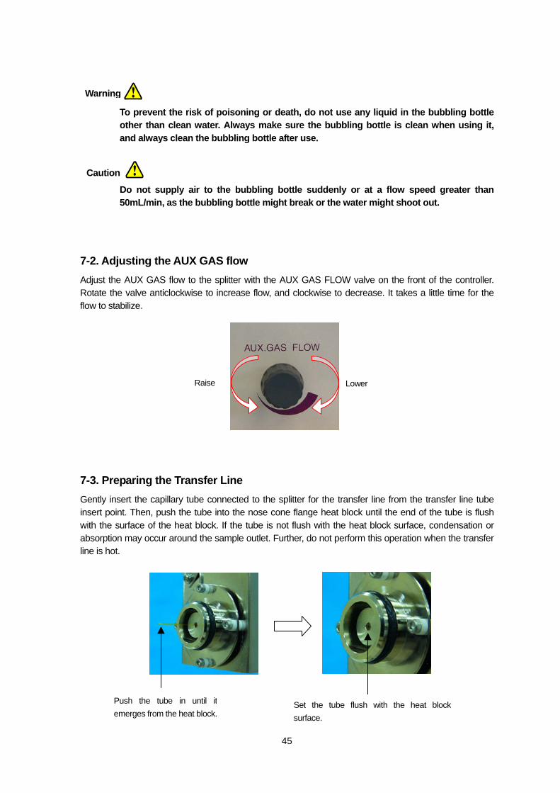
7-2. Adjusting the AUX GAS flow Adjust the AUX GAS flow to the splitter with the AUX GAS FLOW valve on the front of the controller. Rotate the valve anticlockwise to increase flow, and clockwise to decrease. It takes a little time for the flow to stabilize.
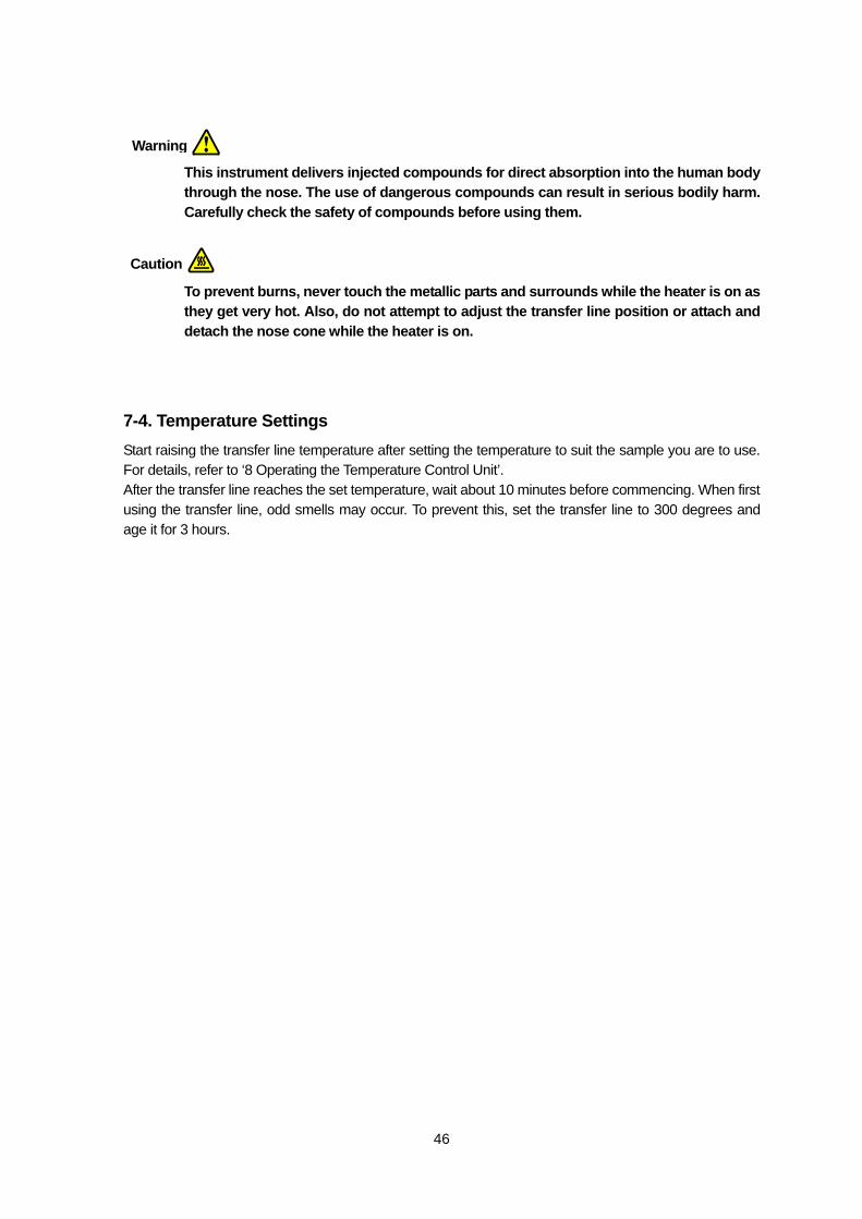
7-3. Preparing the Transfer Line Gently insert the capillary tube connected to the splitter for the transfer line from the transfer line tube insert point. Then, push the tube into the nose cone flange heat block until the end of the tube is flush with the surface of the heat block. If the tube is not flush with the heat block surface, condensation or absorption may occur around the sample outlet. Further, do not perform this operation when the transfer line is hot.
Push the tube in until itemerges from the heat block.
Set the tube flush with the heat block surface.
LowerRaise
Warning
Caution
46
This instrument delivers injected compounds for direct absorption into the human body through the nose. The use of dangerous compounds can result in serious bodily harm. Carefully check the safety of compounds before using them.
To prevent burns, never touch the metallic parts and surrounds while the heater is on as they get very hot. Also, do not attempt to adjust the transfer line position or attach and detach the nose cone while the heater is on.
7-4. Temperature Settings Start raising the transfer line temperature after setting the temperature to suit the sample you are to use. For details, refer to ‘8 Operating the Temperature Control Unit’. After the transfer line reaches the set temperature, wait about 10 minutes before commencing. When first using the transfer line, odd smells may occur. To prevent this, set the transfer line to 300 degrees and age it for 3 hours.
Warning
Caution
47
8. Operating the Temperature Control Unit
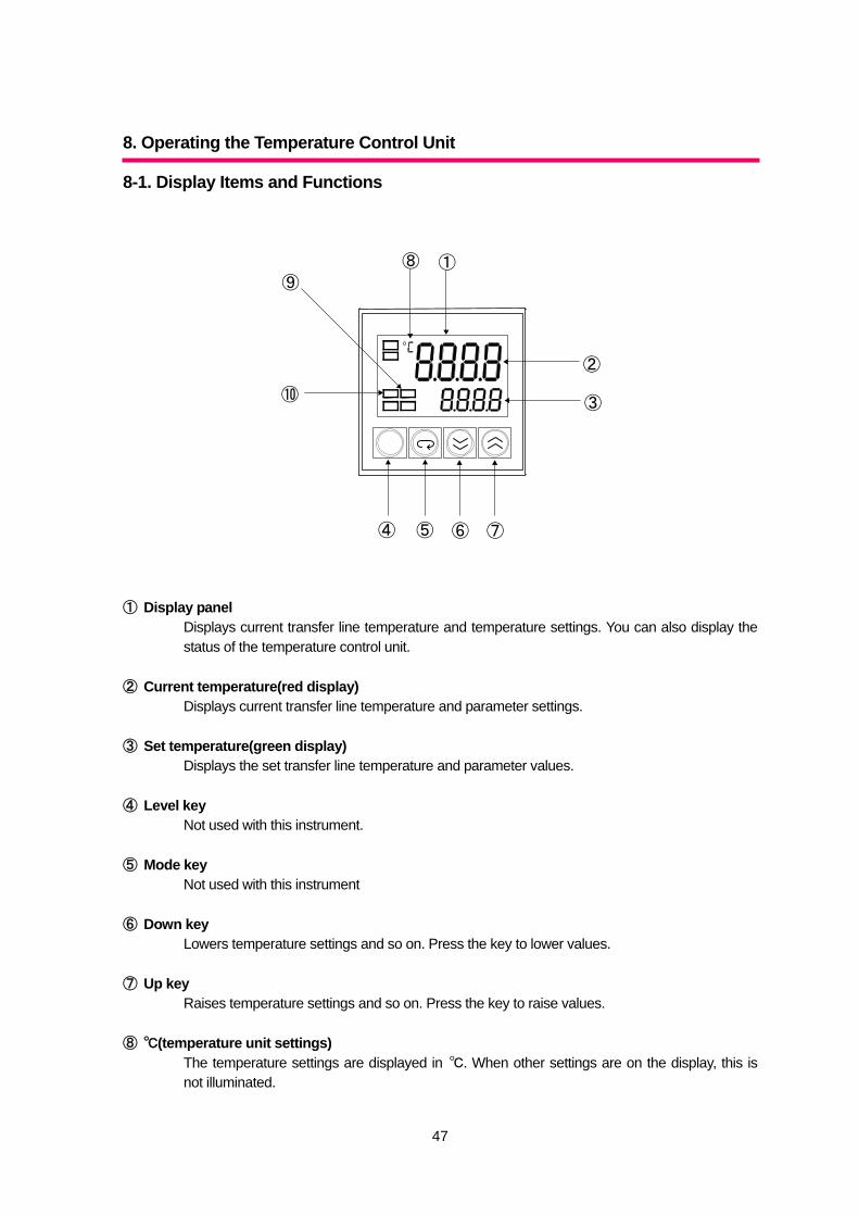
8-1. Display Items and Functions ① Display panel
Displays current transfer line temperature and temperature settings. You can also display the status of the temperature control unit.
② Current temperature(red display)
Displays current transfer line temperature and parameter settings. ③ Set temperature(green display)
Displays the set transfer line temperature and parameter values. ④ Level key
Not used with this instrument. ⑤ Mode key
Not used with this instrument ⑥ Down key
Lowers temperature settings and so on. Press the key to lower values. ⑦ Up key
Raises temperature settings and so on. Press the key to raise values. ⑧ ℃(temperature unit settings)
The temperature settings are displayed in ℃. When other settings are on the display, this is not illuminated.
①
②
③
④ ⑤ ⑥ ⑦
⑧
⑨
⑩
48
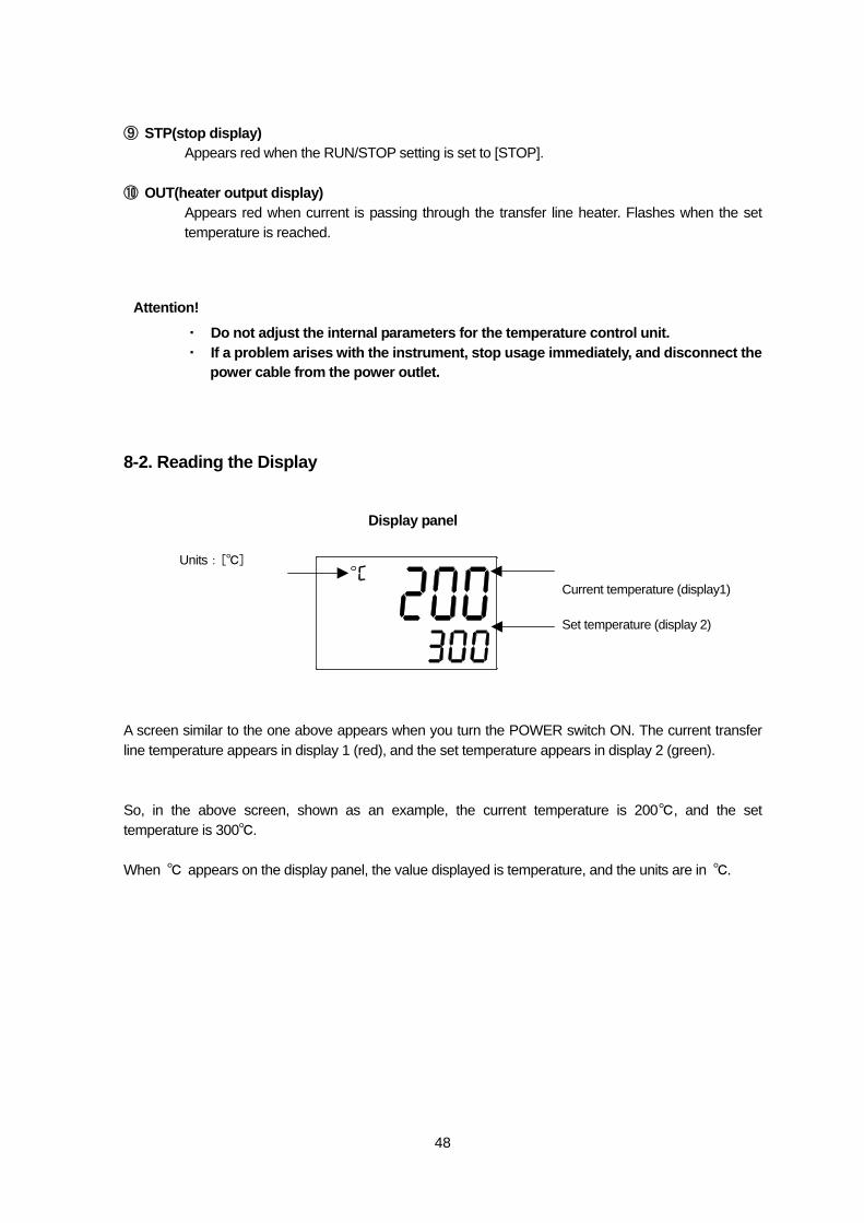
⑨ STP(stop display) Appears red when the RUN/STOP setting is set to [STOP].
⑩ OUT(heater output display)
Appears red when current is passing through the transfer line heater. Flashes when the set temperature is reached.
・ Do not adjust the internal parameters for the temperature control unit. ・ If a problem arises with the instrument, stop usage immediately, and disconnect the
power cable from the power outlet.
8-2. Reading the Display A screen similar to the one above appears when you turn the POWER switch ON. The current transfer line temperature appears in display 1 (red), and the set temperature appears in display 2 (green). So, in the above screen, shown as an example, the current temperature is 200℃, and the set temperature is 300℃. When ℃ appears on the display panel, the value displayed is temperature, and the units are in ℃.
Current temperature (display1)
Set temperature (display 2)
Units:[℃]
Display panel
Attention!
49
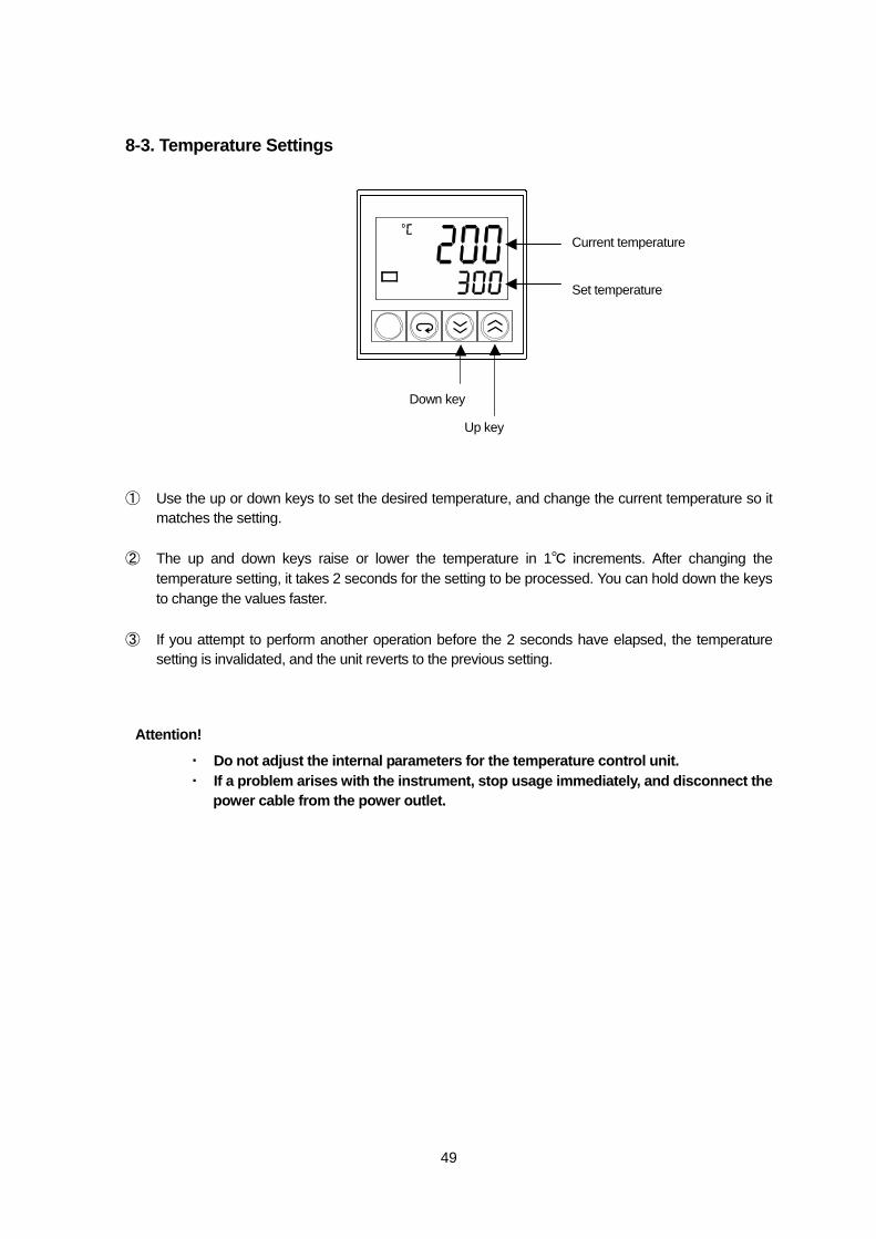
8-3. Temperature Settings ① Use the up or down keys to set the desired temperature, and change the current temperature so it
matches the setting. ② The up and down keys raise or lower the temperature in 1℃ increments. After changing the
temperature setting, it takes 2 seconds for the setting to be processed. You can hold down the keys to change the values faster.
③ If you attempt to perform another operation before the 2 seconds have elapsed, the temperature
setting is invalidated, and the unit reverts to the previous setting.
・ Do not adjust the internal parameters for the temperature control unit. ・ If a problem arises with the instrument, stop usage immediately, and disconnect the
power cable from the power outlet.
Up key
Down key
Current temperature
Set temperature
Attention!
50
9. Split Manager Split Ratio Simulation Software
9-1. Functions ■Split ratio simulation
Enables you to create a simulation before setting up to determine the length and internal diameter of the column, head pressure, temperature, type of AUX GAS, length and internal diameter of the capillary tubes, and the split ratio (flow ratio) for the gas chromatograph detector line and transfer line .
■Capillary tube simulation
Enables you to create a simulation from the desired split ratio to determine the capillary tube lengths required for connection.
■Retention time simulation
Enables you to create a simulation to determine the time (difference) for the sample to pass through the gas chromatograph detector side and the transfer line side.
■Error display
Displays details of errors on the PC monitor, for such errors as incorrect parameter input, unsuitable criteria for simulation and so on. The error display makes it easy to make corrections.
9-2. Set Up It is not necessary to install the software. It can be run straight from the CD ROM, or copied to and executed from the desktop. Click the SplitManager.exe icon on the CD ROM or on the desktop after you have copied it.
Operating System Windows®95, 98, 2000, XP, NT4.0 Media CD-ROM Memory requirements Recommended OS standard Required HD capacity More than1MBfor the program only
51
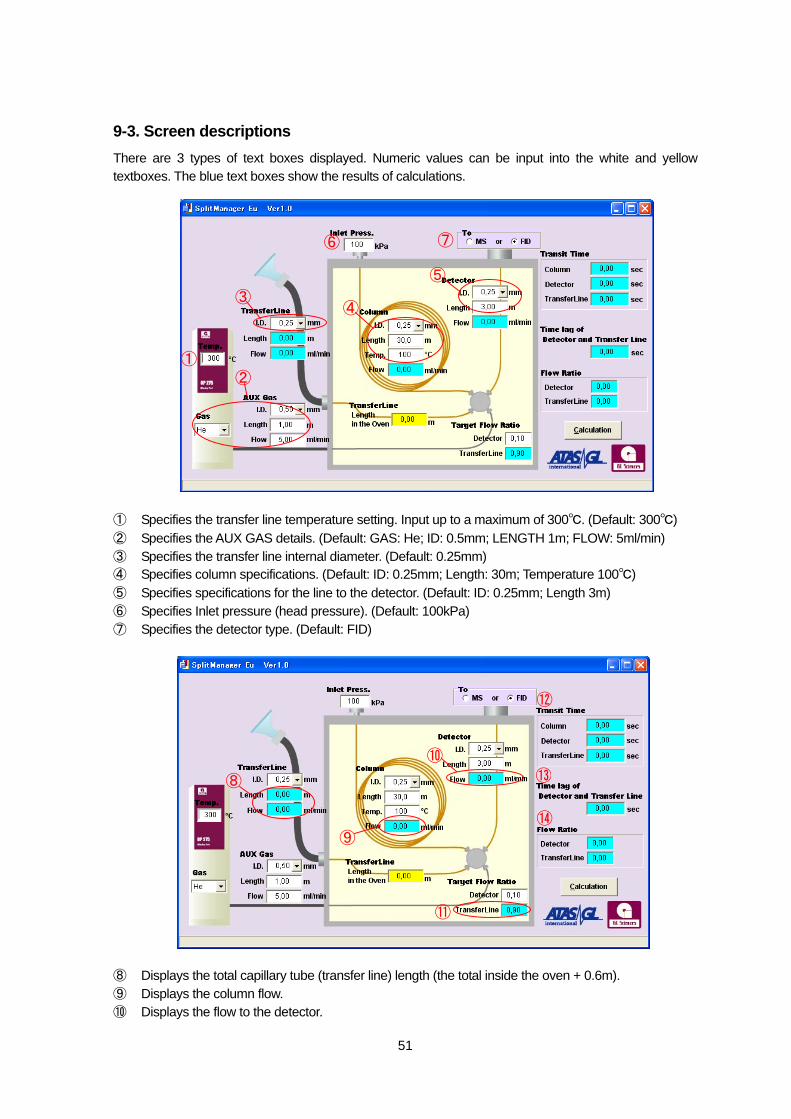
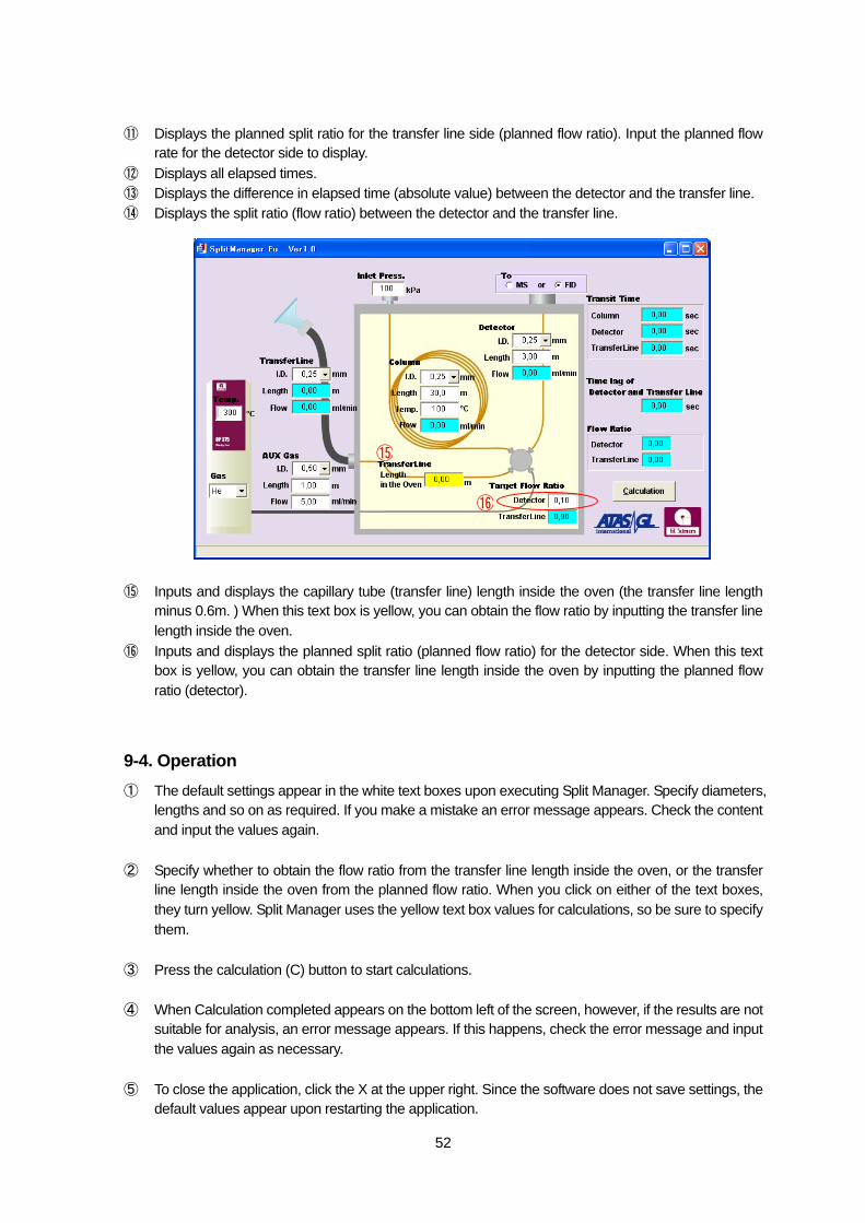
9-3. Screen descriptions There are 3 types of text boxes displayed. Numeric values can be input into the white and yellow textboxes. The blue text boxes show the results of calculations. ① Specifies the transfer line temperature setting. Input up to a maximum of 300℃. (Default: 300℃) ② Specifies the AUX GAS details. (Default: GAS: He; ID: 0.5mm; LENGTH 1m; FLOW: 5ml/min) ③ Specifies the transfer line internal diameter. (Default: 0.25mm) ④ Specifies column specifications. (Default: ID: 0.25mm; Length: 30m; Temperature 100℃) ⑤ Specifies specifications for the line to the detector. (Default: ID: 0.25mm; Length 3m) ⑥ Specifies Inlet pressure (head pressure). (Default: 100kPa) ⑦ Specifies the detector type. (Default: FID) ⑧ Displays the total capillary tube (transfer line) length (the total inside the oven + 0.6m). ⑨ Displays the column flow. ⑩ Displays the flow to the detector.
① ②
③ ④
⑤
⑥ ⑦
⑧
⑨
⑩
⑪
⑫
⑬
⑭
52
⑪ Displays the planned split ratio for the transfer line side (planned flow ratio). Input the planned flow rate for the detector side to display.
⑫ Displays all elapsed times. ⑬ Displays the difference in elapsed time (absolute value) between the detector and the transfer line. ⑭ Displays the split ratio (flow ratio) between the detector and the transfer line. ⑮ Inputs and displays the capillary tube (transfer line) length inside the oven (the transfer line length
minus 0.6m. ) When this text box is yellow, you can obtain the flow ratio by inputting the transfer line length inside the oven.
⑯ Inputs and displays the planned split ratio (planned flow ratio) for the detector side. When this text box is yellow, you can obtain the transfer line length inside the oven by inputting the planned flow ratio (detector).
9-4. Operation ① The default settings appear in the white text boxes upon executing Split Manager. Specify diameters,
lengths and so on as required. If you make a mistake an error message appears. Check the content and input the values again.
② Specify whether to obtain the flow ratio from the transfer line length inside the oven, or the transfer
line length inside the oven from the planned flow ratio. When you click on either of the text boxes, they turn yellow. Split Manager uses the yellow text box values for calculations, so be sure to specify them.
③ Press the calculation (C) button to start calculations. ④ When Calculation completed appears on the bottom left of the screen, however, if the results are not
suitable for analysis, an error message appears. If this happens, check the error message and input the values again as necessary.
⑤ To close the application, click the X at the upper right. Since the software does not save settings, the
default values appear upon restarting the application.
⑮
⑯
53
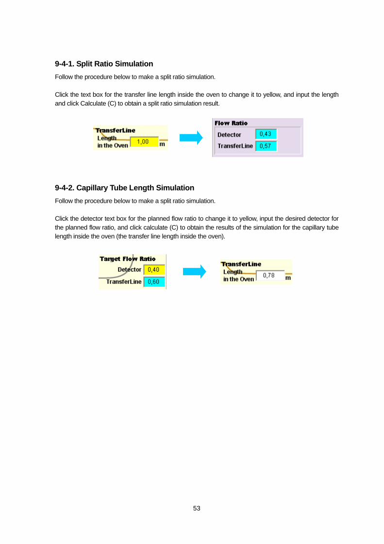
9-4-1. Split Ratio Simulation Follow the procedure below to make a split ratio simulation. Click the text box for the transfer line length inside the oven to change it to yellow, and input the length and click Calculate (C) to obtain a split ratio simulation result.
9-4-2. Capillary Tube Length Simulation Follow the procedure below to make a split ratio simulation. Click the detector text box for the planned flow ratio to change it to yellow, input the desired detector for the planned flow ratio, and click calculate (C) to obtain the results of the simulation for the capillary tube length inside the oven (the transfer line length inside the oven).
54
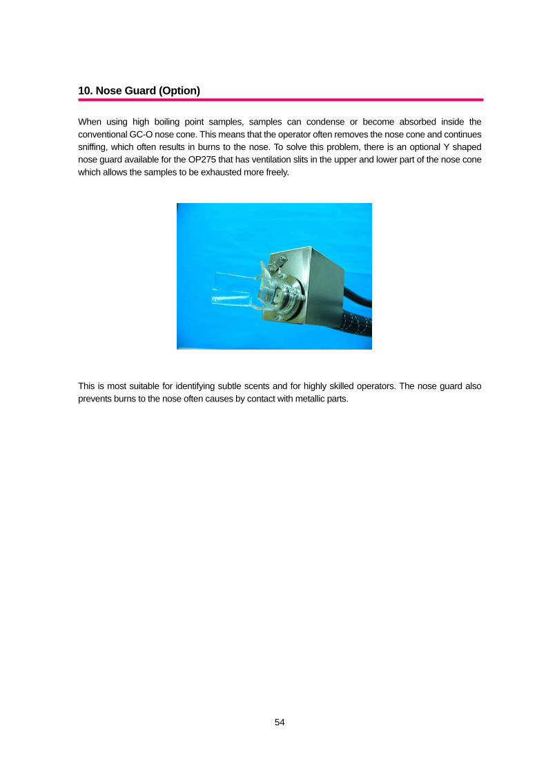
10. Nose Guard (Option) When using high boiling point samples, samples can condense or become absorbed inside the conventional GC-O nose cone. This means that the operator often removes the nose cone and continues sniffing, which often results in burns to the nose. To solve this problem, there is an optional Y shaped nose guard available for the OP275 that has ventilation slits in the upper and lower part of the nose cone which allows the samples to be exhausted more freely. This is most suitable for identifying subtle scents and for highly skilled operators. The nose guard also prevents burns to the nose often causes by contact with metallic parts.
55
11. Maintenance
11-1. Replacing the Fuse ◆When replacing a fuse, be sure to use a replacement fuse of the same rating.
The fuse cartridge is in the AC inlet on the rear panel of the controller. In the cartridge, there is a main fuse and a spare fuse. Use the spare fuse for main fuse replacement if necessary. For details of the spare fuse, refer to ‘20. Parts/Expendables’.
① Remove the power cable from the AC inlet.
② Pull out the fuse cartridge, and replace the main fuse and the spare fuse.
Power fuse rating: 250V T 5A 5.2×20mm
③ Put the fuse cartridge back in the AC inlet, and replace the power cord.
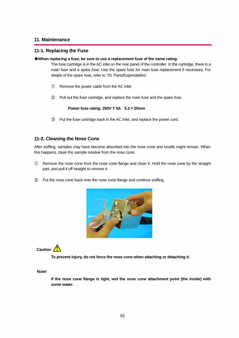
11-2. Cleaning the Nose Cone After sniffing, samples may have become absorbed into the nose cone and smells might remain. When this happens, clean the sample residue from the nose cone. ① Remove the nose cone from the nose cone flange and clean it. Hold the nose cone by the straight
part, and pull it off straight to remove it. ② Put the nose cone back onto the nose cone flange and continue sniffing.
To prevent injury, do not force the nose cone when attaching or detaching it.
If the nose cone flange is tight, wet the nose cone attachment point (the inside) with some water.
Caution
Note!
56
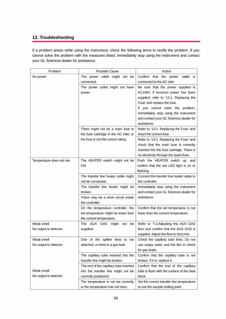
12. Troubleshooting If a problem arises while using the instrument, check the following items to rectify the problem. If you cannot solve the problem with the measures listed, immediately stop using the instrument and contact your GL Sciences dealer for assistance.
Problem Possible Cause Action The power cable might not be connected.
Confirm that the power cable is connected to the AC inlet.
The power outlet might not have power.
Be sure that the power supplied is AC100V. If incorrect power has been supplied, refer to ‘13-1. Replacing the Fuse’ and replace the fuse. If you cannot solve the problem, immediately stop using the instrument and contact your GL Sciences dealer for assistance. Refer to ‘13-1. Replacing the Fuse’ and insert the correct fuse.
No power
There might not be a main fuse in the fuse cartridge in the AC inlet, or the fuse is not the correct rating. Refer to ‘13-1. Replacing the Fuse’ and
check that the main fuse is correctly inserted into the fuse cartridge. There is no electricity through the spare fuse.
The HEATER switch might not be ON.
Push the HEATER switch up, and confirm that the red LED light is on or flashing.
The transfer line heater cable might not be connected.
Connect the transfer line heater cable to the controller.
The transfer line heater might be broken. There may be a short circuit inside the controller.
Immediately stop using the instrument and contact your GL Sciences dealer for assistance.
Temperature does not rise
On the temperature controller, the set temperature might be lower than the current temperature.
Confirm that the set temperature is not lower than the current temperature.
Weak smell No output to detector
The AUX GAS might not be supplied.
Refer to ‘7-2.Adjusting the AUX GAS flow’ and confirm that the AUX GAS is supplied. Adjust the flow to 5mL/min.
One of the splitter lines is not attached, or there is a gas leak.
Check the capillary tube lines. Do not use soapy water and the like to check for gas leaks.
The capillary tube inserted into the transfer line might be broken.
Confirm that the capillary tube is not broken. If it is, replace it.
The end of the capillary tube inserted into the transfer line might not be correctly positioned.
Confirm that the end of the capillary tube is flush with the surface of the heat block.
Weak smell No output to detector Weak smell No output to detector The temperature is not set correctly
or the temperature has not risen. Set the correct transfer line temperature to suit the sample boiling point.
57
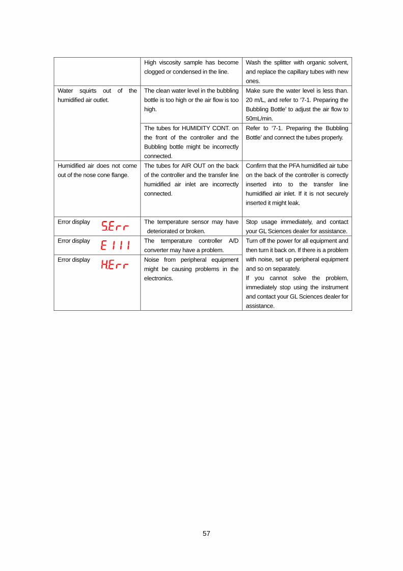
High viscosity sample has become clogged or condensed in the line.
Wash the splitter with organic solvent, and replace the capillary tubes with new ones.
The clean water level in the bubbling bottle is too high or the air flow is too high.
Make sure the water level is less than. 20 m/L, and refer to ‘7-1. Preparing the Bubbling Bottle’ to adjust the air flow to 50mL/min.
Water squirts out of the humidified air outlet.
The tubes for HUMIDITY CONT. on the front of the controller and the Bubbling bottle might be incorrectly connected.
Refer to ‘7-1. Preparing the Bubbling Bottle’ and connect the tubes properly.
Humidified air does not come out of the nose cone flange.
The tubes for AIR OUT on the back of the controller and the transfer line humidified air inlet are incorrectly connected.
Confirm that the PFA humidified air tube on the back of the controller is correctly inserted into to the transfer line humidified air inlet. If it is not securely inserted it might leak.
Error display
The temperature sensor may have deteriorated or broken.
Stop usage immediately, and contact your GL Sciences dealer for assistance.
Error display The temperature controller A/D converter may have a problem.
Error display Noise from peripheral equipment might be causing problems in the electronics.
Turn off the power for all equipment and then turn it back on. If there is a problem with noise, set up peripheral equipment and so on separately. If you cannot solve the problem, immediately stop using the instrument and contact your GL Sciences dealer for assistance.
58
13. Utility specifications
13-1. Olfactory Detector Port OP275 (A) Power supply
Line frequency: 50 to 60Hz Line voltage: 200 to 240V AC Power consumption: Max.500VA (5A) Connection power cable: Grounded 2P+E power outlet or power board
(B) Gas
Auxiliary gas: High purity helium or nitrogen AIR: Pure air or nitrogen (general grade)
(C) Pressure
Auxiliary gas: 0.1 to 0.7MPa (recommended 0.3 to 0.5MPa) AIR: 0.1 to 0.6MPa (recommended 0.3 to 0.5MPa)
(D) Flow range
Auxiliary gas: 0 to 5mL/min (recommended 5mL/min) AIR: 0 to 50mL/min (recommended 50mL/min)
(E) Gas pipes
Auxiliary gas IN: 1/8inch (3.175mm) SL tube connection Auxiliary gas OUT: 1/16inch (1.588mm) SL tube connection AIR IN: 1/8inch (3.175mm) SL tube connection AIR OUT: 1/8inch (3.175mm) one touch tube connection
(F) Clean water
Amount: 10 to 20mL (Bubbling Bottle: 40mL) (G) Primary gas supply regulator
High sensitivity regulator for analysis purposes Rubber diaphragm, seal tape is not suitable. (H) Tubing materials
The minimum required for set up and first use are provided as standard. For details, refer to ’15. Packing List’. Please prepare other parts and expendables to suit your requirements. For details, refer to ’16. Parts/Expendables’.
59
13-2. Split Manager (Split Ratio Simulation Software) Recommended system requirements
Operating System: Windows®95, 98, 2000, XP, NT4.0 Media: CD-ROM Memory requirements: Recommended OS standard Required HD capacity: More than1MB for the program only
*This software has been confirmed to run on Windows® 2000, and Windows® XP
*This software does not require installation. It can be executed from the CD ROM, or copied to the desktop and
executed from there.
*Acrobat Reader is required to read the software operations manual.
60
14. Specifications
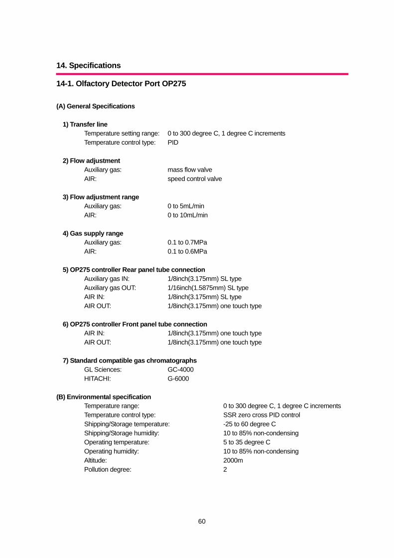
14-1. Olfactory Detector Port OP275 (A) General Specifications
1) Transfer line Temperature setting range: 0 to 300 degree C, 1 degree C increments Temperature control type: PID
2) Flow adjustment
Auxiliary gas: mass flow valve AIR: speed control valve
3) Flow adjustment range
Auxiliary gas: 0 to 5mL/min AIR: 0 to 10mL/min
4) Gas supply range
Auxiliary gas: 0.1 to 0.7MPa AIR: 0.1 to 0.6MPa
5) OP275 controller Rear panel tube connection
Auxiliary gas IN: 1/8inch(3.175mm) SL type Auxiliary gas OUT: 1/16inch(1.5875mm) SL type AIR IN: 1/8inch(3.175mm) SL type AIR OUT: 1/8inch(3.175mm) one touch type
6) OP275 controller Front panel tube connection
AIR IN: 1/8inch(3.175mm) one touch type AIR OUT: 1/8inch(3.175mm) one touch type
7) Standard compatible gas chromatographs
GL Sciences: GC-4000 HITACHI: G-6000
(B) Environmental specification
Temperature range: 0 to 300 degree C, 1 degree C increments Temperature control type: SSR zero cross PID control Shipping/Storage temperature: -25 to 60 degree C Shipping/Storage humidity: 10 to 85% non-condensing Operating temperature: 5 to 35 degree C Operating humidity: 10 to 85% non-condensing Altitude: 2000m Pollution degree: 2
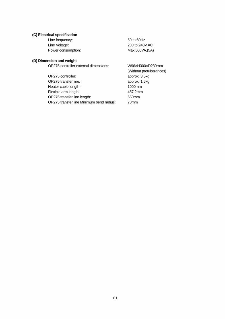
61
(C) Electrical specification Line frequency: 50 to 60Hz Line Voltage: 200 to 240V AC Power consumption: Max.500VA,(5A)
(D) Dimension and weight
OP275 controller external dimensions: W96×H300×D230mm (Without protuberances)
OP275 controller: approx. 3.5kg OP275 transfer line: approx. 1.5kg Heater cable length: 1000mm Flexible arm length: 457.2mm OP275 transfer line length: 650mm OP275 transfer line Minimum bend radius: 70mm
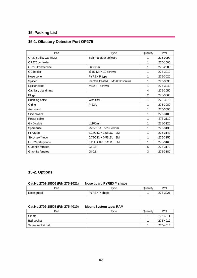
62
15. Packing List
15-1. Olfactory Detector Port OP275
Part Type Quantity P/N OP275 utility CD-ROM Split manager software 1 275-9999 OP275 controller 1 275-1000 OP275transfer line L650mm 1 275-2000 GC holder φ15, M4×10 screws 1 275-3010 Nose cone PYREX R type 1 275-3020 Splitter Inactive treated, M3×12 screws 1 275-3030 Splitter stand M4×8 screws 1 275-3040 Capillary gland nuts 4 275-3050 Plugs 2 275-3060 Bubbling bottle With filter 1 275-3070 O ring P-22A 1 275-3080 Arm stand 1 275-3090 Side covers 1 275-3100 Power cable 1 275-3110 GND cable L1100mm 1 275-3120 Spare fuse 250VT 5A 5.2×20mm 1 275-3130 PFA tube 3.18O.D.×1.58I.D. 2M 1 275-3140 Silcosteel® tube 0.79O.D.×0.53I.D. 2M 1 275-3150 F.S. Capillary tube 0.25I.D.×0.35O.D. 5M 1 275-3160 Graphite ferrules GI-0.5 5 275-3170 Graphite ferrules GI-0.8 3 275-3180
15-2. Options Cat.No.2702-18506 (P/N 275-3021) Nose guard PYREX Y shape
Part Type Quantity P/N Nose guard PYREX Y shape 1 275-3021 Cat.No.2702-18508 (P/N 275-4010) Mount System type: RAM
Part Type Quantity P/N Clamp 1 275-4011 Ball socket 1 275-4012 Screw socket ball 1 275-4013
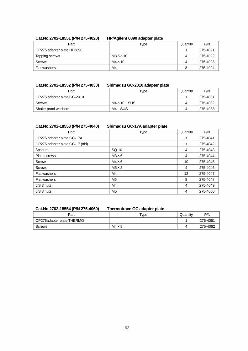
63
Cat.No.2702-18551 (P/N 275-4020) HP/Agilent 6890 adapter plate Part Type Quantity P/N
OP275 adapter plate HP6890 1 275-4021 Tapping screws M3.5×10 4 275-4022 Screws M4×10 4 275-4023 Flat washers M4 8 275-4024 Cat.No.2702-18552 (P/N 275-4030) Shimadzu GC-2010 adapter plate
Part Type Quantity P/N OP275 adapter plate GC-2010 1 275-4031 Screws M4×10 SUS 4 275-4032 Shake-proof washers M4 SUS 4 275-4033 Cat.No.2702-18553 (P/N 275-4040) Shimadzu GC-17A adapter plate
Part Type Quantity P/N OP275 adapter plate GC-17A 1 275-4041 OP275 adapter plate GC-17 (old) 1 275-4042 Spacers SQ-10 4 275-4043 Plate screws M3×6 4 275-4044 Screws M4×6 10 275-4045 Screws M5×8 4 275-4046 Flat washers M4 12 275-4047 Flat washers M5 8 275-4048 JIS 3 nuts M4 4 275-4049 JIS 3 nuts M5 4 275-4050 Cat.No.2702-18554 (P/N 275-4060) Thermotrace GC adapter plate
Part Type Quantity P/N OP275adapter plate THERMO 1 275-4061 Screws M4×8 4 275-4062
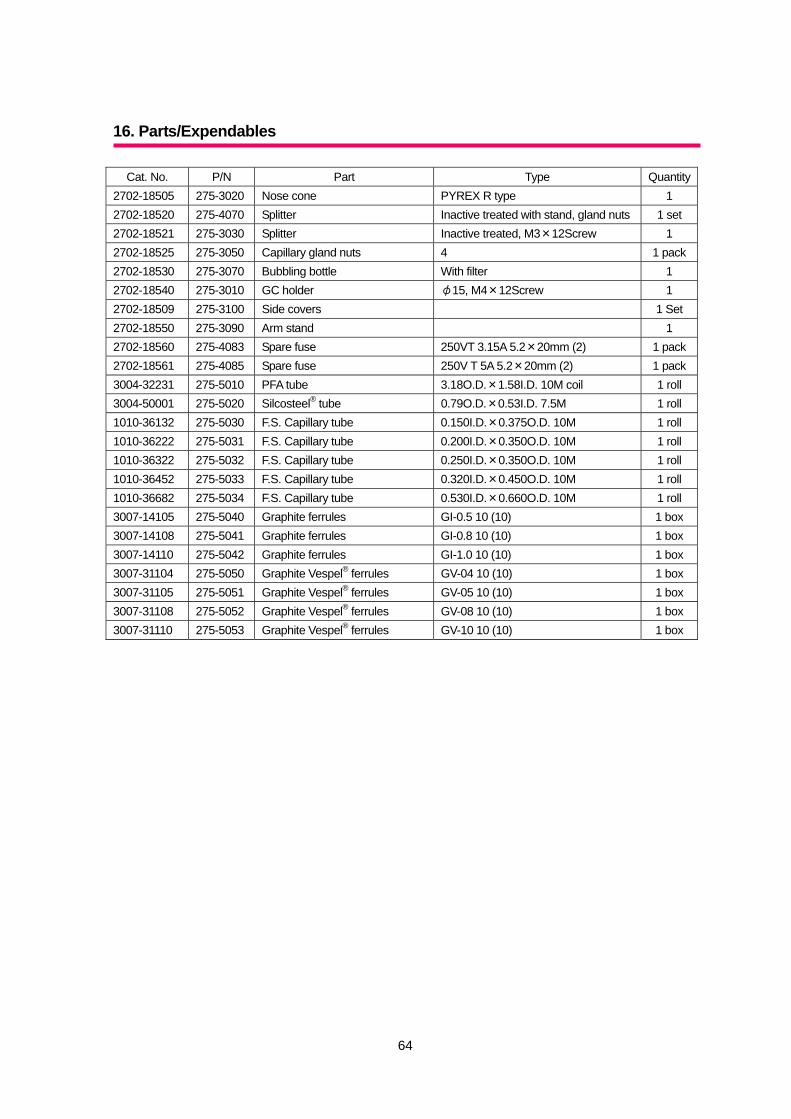
64
16. Parts/Expendables
Cat. No. P/N Part Type Quantity2702-18505 275-3020 Nose cone PYREX R type 1 2702-18520 275-4070 Splitter Inactive treated with stand, gland nuts 1 set 2702-18521 275-3030 Splitter Inactive treated, M3×12Screw 1 2702-18525 275-3050 Capillary gland nuts 4 1 pack2702-18530 275-3070 Bubbling bottle With filter 1 2702-18540 275-3010 GC holder φ15, M4×12Screw 1 2702-18509 275-3100 Side covers 1 Set 2702-18550 275-3090 Arm stand 1 2702-18560 275-4083 Spare fuse 250VT 3.15A 5.2×20mm (2) 1 pack2702-18561 275-4085 Spare fuse 250V T 5A 5.2×20mm (2) 1 pack3004-32231 275-5010 PFA tube 3.18O.D.×1.58I.D. 10M coil 1 roll 3004-50001 275-5020 Silcosteel® tube 0.79O.D.×0.53I.D. 7.5M 1 roll 1010-36132 275-5030 F.S. Capillary tube 0.150I.D.×0.375O.D. 10M 1 roll 1010-36222 275-5031 F.S. Capillary tube 0.200I.D.×0.350O.D. 10M 1 roll 1010-36322 275-5032 F.S. Capillary tube 0.250I.D.×0.350O.D. 10M 1 roll 1010-36452 275-5033 F.S. Capillary tube 0.320I.D.×0.450O.D. 10M 1 roll 1010-36682 275-5034 F.S. Capillary tube 0.530I.D.×0.660O.D. 10M 1 roll 3007-14105 275-5040 Graphite ferrules GI-0.5 10 (10) 1 box 3007-14108 275-5041 Graphite ferrules GI-0.8 10 (10) 1 box 3007-14110 275-5042 Graphite ferrules GI-1.0 10 (10) 1 box 3007-31104 275-5050 Graphite Vespel® ferrules GV-04 10 (10) 1 box 3007-31105 275-5051 Graphite Vespel® ferrules GV-05 10 (10) 1 box 3007-31108 275-5052 Graphite Vespel® ferrules GV-08 10 (10) 1 box 3007-31110 275-5053 Graphite Vespel® ferrules GV-10 10 (10) 1 box

Olfactory Detector Port OP275 Operations Manual
・Issued: 4th April 2007 Version 2 ・Publisher: GL Sciences Inc.
Reprinting prohibited (Not for sale) 2007 Printed In Japan