oli overview and status - landsat missions overview and status edward j. knight, ... ktp reqt jul-08...
TRANSCRIPT

OLI Overview and StatusEdward J. Knight, Ph.D.
Landsat Science Team Meeting7/15/08
Outline
Instrument OverviewSubsystem StatusPreliminary DataConclusion

Instrument Overview

OLI Maintains Landsat Legacy
Landsat Continuity Mission demands─ Accurate spectral and spatial information ─ Frequent synoptic earth views─ NIST calibrated over time ─ Precise geo-referenced data
Band Name
Band (nm)
Bandwidth (nm)
GSD (m) SNR
Coastal/Aerosol 443 20 30 130
Blue 482 65 30 130Green 562 75 30 100Red 655 50 30 90NIR 865 40 30 90SWIR 1 1610 100 30 100SWIR 2 2200 200 30 100PAN 590 180 15 80Cirrus 1375 30 30 50
Visible/NIR SWIR
Key instrument parameters─ Cross-track FOV 185 km ─ S/C altitude 705 km─ Geodetic accuracy*
Absolute 65 m Relative 25 m
─ Geometric accuracy** Absolute 12 m
*No terrain compensation**w/ terrain compensation
0
100
200
300
400
500
600
700
0.4 0.6 0.8 1 1.2 1.4 1.6 1.8 2 2.2 2.4Wavelength (microns)
Rad
ianc
e (W
/cm
^2/s
r/um
)
0
1
Desert Spectrum Vegetation Spectrum TOA SolarLtyp L high L SaturationCoastal Aerosol Blue GreenRed NIR SWIR 1SWIR 2 Pan Chromatic Cirrus

Driving Performance Requirements
Radiometric─ Signal-to-noise radiometric stability
(16-day, 60 sec, 5 year)─ Pixel-to-pixel uniformity─ Absolute radiometric accuracy
Absolute radiance – 5%, absolute reflectance – 3%Spectral─ Spectral band edges and center
wavelength tolerance─ Integrated out-of-band (OOB) response
(<2%)─ Spectral uniformity (FWHM) (± 3%)
Spatial─ Edge response─ Aliasing─ Light rejection and internal scattering─ Ghosting
Geometric─ Band-to-band co-registration (4.5 m)─ Absolute geodetic accuracy (65 m)
#
Minimum Lower
Band Edge (nm)
Maximum Upper
Band Edge (nm)
SNR at LTypical
SNR at LHigh
1 433 453 130 2902 450 515 130 3603 525 600 100 3904 630 680 90 3405 845 885 90 4606 1560 1660 100 5407 2100 2300 100 5108 500 680 80 2309 1360 1390 50 N/A
OLI Band and SNR Specs

Baseline Design and Descriptive Block Diagram
Pushbroom VIS/SWIR sensorFour mirror telescope with front aperture stopFPA consisting of 14 sensor chip assemblies, passively cooled

Key Technical Parameter (KTP) Performance Summary
Meeting all key requirements with margin
Mass and power are reported for both current best estimate (CBE) and “mature” values, which include Ball Aerospace growth factors─ “Current Best Estimate” is the designer’s estimate─ Mature mass / mature power reflects historical growth. i.e., it’s contingency
Margin is low for coregistration simply due to an ‘allocation’ issue─ Spacecraft predictions for attitude control exceed their requirements and have not been
captured in the budgets yet
KTP Reqt Jul-08 Margin (%) Units CommentsMass 375.0 274.6, 306.7 37,22 kg CBE, Mature MassPeak Power (Imaging) 375 290.3, 309.3 43,15.6 W CBE, Mature PowerAverage Power (Imaging) 200 164.4,183.4 33,11 W CBE, Mature PowerData Rate 265 243.65 8.8 Mbps Reqt. is NTESNR 130 59 - % Worst case margin at Ltyp (C/A band)Edge Response Slope 0.027/m 5.5 - % Worst case margin (BLUE AT)Abs. Rad. Accuracy 5.0 4.2 19 %Radiometric Stability 1.00 0.65 54 % Worst band (C/A); Fixed defnPixel-to-Pixel Uniform. 0.25 0.2 15 % Banding C/A BandAbsolute Geodetic Accuracy 65 51.12 27.2 mBand-to-Band Reg. Accuracy 4.5 4.39/4.37 2.4 m AT/XT

OLI One-Page Schedule

Subsystem Status

Flight Optics Are in Final Polishing Operations at Tinsley
Flight Secondary Mirror at Final Edging (now in edge polish)
Flight Quaternary MirrorAfter Aspheric Shaping
Flight Primary MirrorPrior to Final Polishing
Flight Tertiary Mirror Silvered for WFE Testing

Main Bench Assembly Takes Shape
ATK technicians bond FPA bulkhead into bottom bulkhead as main bench assembly takes shape

Focal Plane Consists of 14 Modules
Focal Plane Module
Each Module contains Silicon and HgCdTe detectors mounted on a single readout chip (ROIC) ─ Spectral Filters above the detectors provide separation into bands
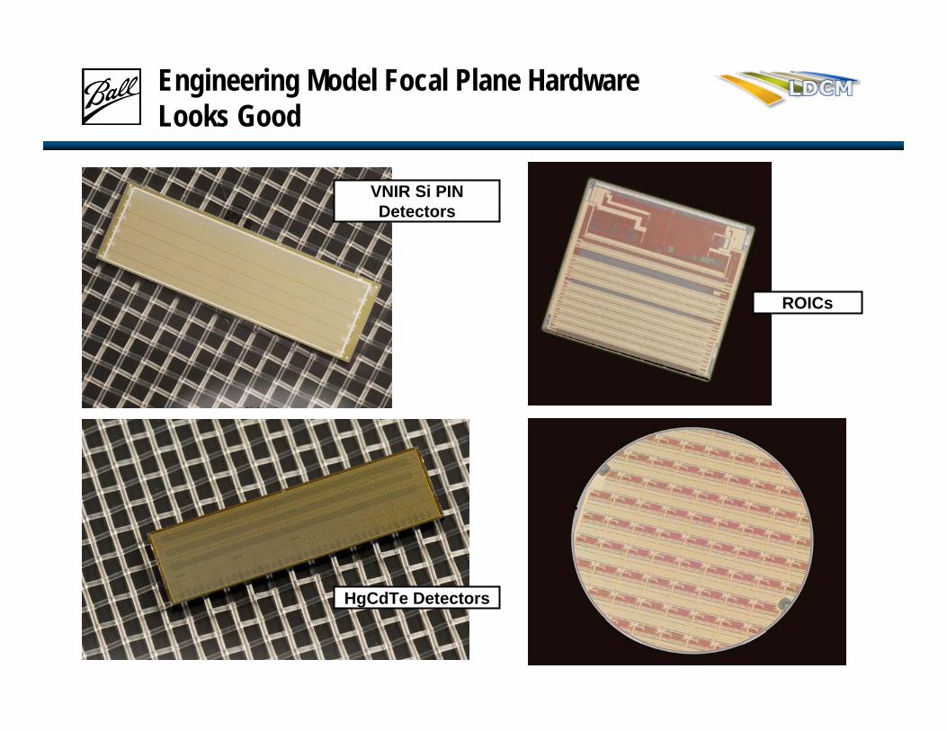
Engineering Model Focal Plane Hardware Looks Good
HgCdTe Detectors
ROICs
VNIR Si PIN Detectors

Engineering Unit Electronics Boards Are Being Populated

Thermal Control Design
FPA Radiator
FPE Radiator
Heat Pipe Support FPE Heat Pipe
FPA Heat Pipes
FPE
FPA
Support Truss
+X UP ORIENTATION
Design integrated onto instrument

Calibration Subassembly Consists of Five Subassemblies
─ 3 LightShade Assemblies─ 1 Diffuser Assembly ─ 1 Shutter Assembly
EntranceLightShade
Diffuser Assembly
Aft LightShade
Exploded View of Calibration Subassembly
SolarLightShade
Shutter Assembly
Stim Lamp Assemblies redesigned to increase emitted light and optimize monitoring diode position
Diodes view diffuser instead of housing wallNo direct view of any lamps
Calibration Detailed Design Underway

Ball Aerospace Algorithms Cover Both On-line and Off-line Processing
LDCM CPF
LDCM Archive
database
Retrieve Data
Prepare Ancillary Data
for Input to Ball Code
L0 Image Construction
Parse Data
Radiometric Processing
Geometric Processing
Product Generation
Ball/LDCM
Archive database
Evaluation of Results
Ball Performance, off-line Analysis, Track
and Trend Tools
Updateyes
yes
Stop
no
Data Ingest Radiometric Processing
Geometric Processing
Product Generation
Ball Data Analysis System
LDCM IPE
Collaborative Decision
Ball Calibration Parameter Files (CPF)
Ball On-Line Processing Ball Off-Line Processing
Processing Algorithm
Radiometric Algorithms
Geometric Algorithms

Preliminary Data

HgCdTe SWIR Pilot Lot Material Meets Specifications for Quantum Efficiency
Cutoff wavelength is high enough that we’ll have good response in the SWIR─ Good QE─ Good spectral
flatness
0
0.1
0.2
0.3
0.4
0.5
0.6
0.7
0.8
0.9
1
0 1 2 3
Wavelength (um)
Relative Response / Photon
B07 2.49u
B08 2.49u
B09 2.49u
B18 2.49u
Line Diode Cutoff
SWIR
2

HgCdTe SWIR Material Exhibits Low Dark Current and Excellent Dark Current Uniformity
Measurement Data on Pilot Lot Test Structures
Lower is better; values show meet dark current requirementsLower is better; values show
meet dark current requirements
Median Leakage Current at 20 mV Bias for Various Mini-arrays LDCM Pilot Lot 1 TSAs
636735 636736 636737 636738 636739 636740 636741 636742
TSA
Med
ian
Leak
age
Cur
rent
(A)
DJL
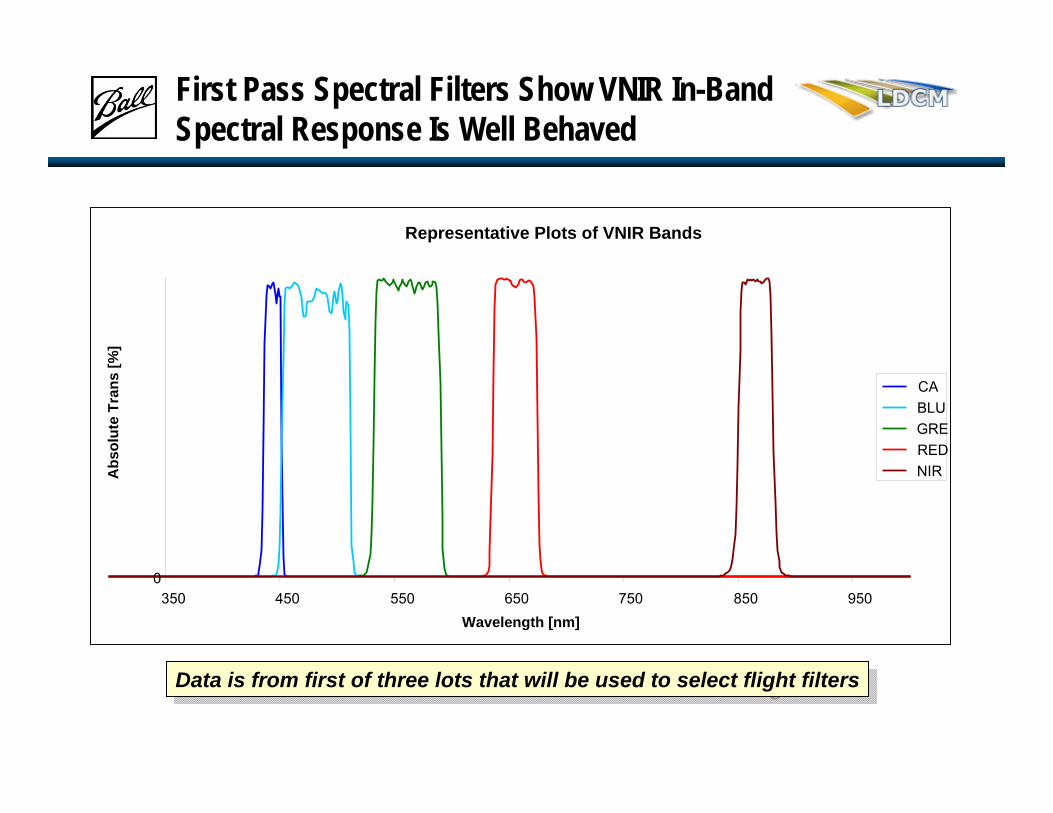
First Pass Spectral Filters Show VNIR In-Band Spectral Response Is Well Behaved
Data is from first of three lots that will be used to select flight filtersData is from first of three lots that will be used to select flight filters
Representative Plots of VNIR Bands
0350 450 550 650 750 850 950
Wavelength [nm]
Abs
olut
e Tr
ans
[%]
CABLUGREREDNIR

Pan and SWIR Spectral Response Is Excellent
Data is from first of three lots that will be used to select flight filtersData is from first of three lots that will be used to select flight filters
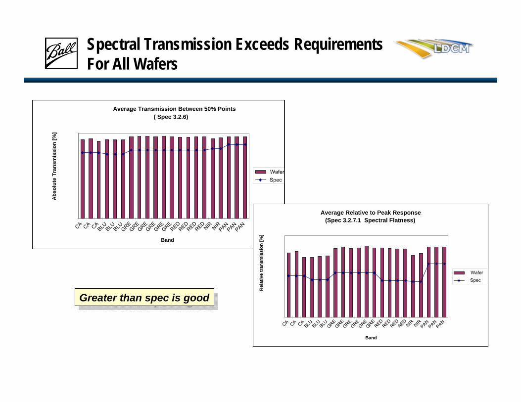
Average Transmission Between 50% Points( Spec 3.2.6)
CA CA CABLU BLUBLUGREGREGREGREGREGREREDREDREDREDNIR NIRPANPANPAN
Band
Abs
olut
e Tr
ansm
issi
on [%
]
WaferSpec
Spectral Transmission Exceeds Requirements For All Wafers
Greater than spec is goodGreater than spec is good
Average Relative to Peak Response(Spec 3.2.7.1 Spectral Flatness)
CA CA CABLU BLU BLU GREGREGREGREGREGREREDREDREDREDNIR NIRPANPANPAN
Band
Rel
ativ
e tr
ansm
issi
on [%
]
WaferSpec

Spectral and Scatter Out-of-Band Response Meet EDU and Most Flight Requirements
(Spec 3.2.9.1)
(Spec 3.2.10)
Less than spec is goodLess than spec is good
Initial results indicated we don’t have the
“VIIRS filter problem.”
CA spectral OBR being addressed in Lots 2 and 3CA spectral OBR being
addressed in Lots 2 and 3
Preliminary Scatter OBR
CA CA CABLUBLU BLUGREGREGREGREGREGREREDREDREDREDNIR NIRPANPANPAN
Band
SOB
R [%
]
WaferReqmt
Preliminary Spectral OBR
CA CA CABLU BLU BLUGREGREGREGREGREGREREDREDREDREDNIR NIRPANPANPAN
Band
OB
R [%
]
WaferReqmt

Summary

Summary
OLI is on scheduleRequirements and Design are stableHardware’s starting to roll inPreliminary data from focal planes and filters is all positive