om - industrial equipment auctions | lab equipment auctions · · 2017-06-11tetra alcip...
TRANSCRIPT

2.21
2134
2401
01fr
o.fm
OM
Doc No. OM-1213424-0101
Tetra Alcip® 10TPOP MINI
Operation Manual

This document is valid for:
Series No/ Machine No
OMOperation Manual
2.21
2134
2401
01fr
o.fm
Issue 2002-01
Tetra Pak Dairy & Beverage Systems AB
Doc No. OM-1213424-0101

Table of contents 2.
2121
3424
0101
toc.
fm
Introduction . . . . . . . . . . . . . . . . . . . . . . . . . . . . . . . . . . . . 1
Equipment . . . . . . . . . . . . . . . . . . . . . . . . . . . . . . . . . . . . . . . . . . 1
Document. . . . . . . . . . . . . . . . . . . . . . . . . . . . . . . . . . . . . . . . . . . 2
Safety precautions . . . . . . . . . . . . . . . . . . . . . . . . . . . . . . 3
Use of hazard information . . . . . . . . . . . . . . . . . . . . . . . . . . . . . . 3
General . . . . . . . . . . . . . . . . . . . . . . . . . . . . . . . . . . . . . . . . . . . . 4
Cleaning solution . . . . . . . . . . . . . . . . . . . . . . . . . . . . . . . . . . . . . 5
General description. . . . . . . . . . . . . . . . . . . . . . . . . . . . . . 7
Application . . . . . . . . . . . . . . . . . . . . . . . . . . . . . . . . . . . . . . . . . . 7
Requirements on personnel . . . . . . . . . . . . . . . . . . . . . . . . . . . . . 7
Operator station . . . . . . . . . . . . . . . . . . . . . . . . . . . . . . . . . . . . . . 7
Risk area . . . . . . . . . . . . . . . . . . . . . . . . . . . . . . . . . . . . . . . . . . . 7
Denominations . . . . . . . . . . . . . . . . . . . . . . . . . . . . . . . . . . . . . . . 8
Process description . . . . . . . . . . . . . . . . . . . . . . . . . . . . 11
Control panel . . . . . . . . . . . . . . . . . . . . . . . . . . . . . . . . . . 19
Denomination . . . . . . . . . . . . . . . . . . . . . . . . . . . . . . . . . . . . . . . 19
General rules for indication . . . . . . . . . . . . . . . . . . . . . . . . . . . . 20
Control system menu tree . . . . . . . . . . . . . . . . . . . . . . . . . . . . . 23
List of alarms . . . . . . . . . . . . . . . . . . . . . . . . . . . . . . . . . . . . . . . 37
Preparations . . . . . . . . . . . . . . . . . . . . . . . . . . . . . . . . . . 39
Manual preparation . . . . . . . . . . . . . . . . . . . . . . . . . . . . . . . . . . 39
Preparation with metering pump . . . . . . . . . . . . . . . . . . . . . . . . 41
Preparation using the by-pass . . . . . . . . . . . . . . . . . . . . . . . . . . 42
Operation . . . . . . . . . . . . . . . . . . . . . . . . . . . . . . . . . . . . . 45
Initial start of cleaning . . . . . . . . . . . . . . . . . . . . . . . . . . . . . . . . 45
Cleaning of package machine (optional) . . . . . . . . . . . . . . . . . . 46
Initial start of stations programs . . . . . . . . . . . . . . . . . . . . . . . . . 47
Stepping of cleaning cycle . . . . . . . . . . . . . . . . . . . . . . . . . . . . . 47
Drain of tank. . . . . . . . . . . . . . . . . . . . . . . . . . . . . . . . . . . . . . . . 48
iTetra Alcip® 10 TPOP MINIDoc No. OM-1213424-0101

Table of contents
2.21
2134
2401
01to
c.fm
Cleaning . . . . . . . . . . . . . . . . . . . . . . . . . . . . . . . . . . . . . . 49
Settings . . . . . . . . . . . . . . . . . . . . . . . . . . . . . . . . . . . . . . 51
Inspection/change of parameter values . . . . . . . . . . . . . . . . . . . 51
Inspection/change of controllers . . . . . . . . . . . . . . . . . . . . . . . . 53
ii Tetra Alcip® 10 TPOP MINIDoc No. OM-1213424-0101

Introduction2.
2 tf5
0163
2en.
fm
IntroductionThis section contains basic information about this manual and the Tetra Pak equipment described.
To ensure maximum safety, always read the section Safety precautions before carrying out any work on the unit.
EquipmentIntended use of this Tetra Pak equipmentThis unit is intended for use according to the specifications in Technical data (see Technical Manual) and related documents.
Tetra Pak will not be held responsible for injury or damage if the equipment is used for any other purpose.
ServiceIf problems are encountered when operating the unit, contact the nearest Tetra Pak service station.
ManufacturerThis Tetra Pak equipment was produced by:
Tetra Pak Dairy & Beverage Systems ABBox 64S-221 00 LUNDSweden
Unit identificationAll units carry a machine plate stating:
– unit identification
– data unique to the unit
Have this information available before contacting Tetra Pak concerning this particular unit.
WARNING!
Mach ine Type
Draw ing Spec .
Mach ine No .
Manu fac tu re r
Year o f manufacture
Tetra Pak
1Tetra Alcip® 10 TPOP MINIDoc No. OM-1213424-0101
Introduction
2.2
tf501
632e
n.fm
DocumentOperation Manual (OM)The purpose of this Operation Manual is to provide the operator with information on how to operate the machine.
Tetra Pak recommend that you study it carefully, and - above all - ensure its availability to those who will be operating the unit.
Furthermore, it is important that you:
– keep the manual for the life of the equipment
– pass the manual on to any subsequent owner or user of the equipment.
Tetra Pak will not be held responsible for any breakdown of the equipment caused by the owner’s failure to follow the instructions given in this manual.
Design modificationsThe information given in this document is in accordance with the design and construction of the machine at the time it was delivered by the Tetra Pak machine production facility.
Further copiesAdditional copies can be ordered from the nearest Tetra Pak service station.
When ordering technical publications, always quote the document number printed on the front cover of the document concerned.
Document producerThis document was produced by:
Tetra Pak Dairy & Beverage Systems ABBox 64S-221 00 LUNDSweden
Number of pagesThis document contains a total of 56 pages.
Copyright 2001 Tetra Pak Dairy & Beverage Systems ABAll rights reserved. No parts of this document or application software used in the product may be edited, reproduced or copied in any form or by any means without the written permission of Tetra Pak Dairy & Beverage Systems AB.
2 Tetra Alcip® 10 TPOP MINIDoc No. OM-1213424-0101

Safety precautions2.
2 tf0
0001
7en.
fm
Safety precautionsTo ensure maximum safety for the operator, always read this section carefully before carrying out any work on the machine or making any adjustments.
Use of hazard information
Failure to observe this information results in immediate danger to life.
Failure to observe this information can result in major personal injury or loss of life
Caution! Failure to observe this information can result in minor personal injury or damage to the equipment.
DANGER!
WARNING!
3Tetra Alcip® 10 TPOP MINIDoc No. OM-1213424-0101

Safety precautions
2.2
tf000
017e
n.fm
GeneralOnly trained personnel are allowed to operate the machine. The machine may only be used in accordance with the instructions given in the manuals delivered with the equipment.
If the safety precautions are not followed, there is risk of personal injury.
This is an automated machine. It is controlled by a process controller and will change its mode of operation without operator intervention. All personnel must therefore:
• stay outside the safety area
• regard all electrical equipment as live
• regard all pipes as hot
• use hearing protection.
Before carrying out maintenance and repair:
• shut off main steam supply
• switch off power
• allow the machine to cool down and adjust to atmospheric pressure
• rinse out concentrated chemicals and cleaning solution with water from pipes and pumps
• inform the operator and other relevant personnel about the work you intend to do
• post warning signs in prominent places.
Pipes and other parts of this machine may be hot. Contact with hot equipment may result in severe burns. Avoid contact with hot equipment.
This machine operates under pressurized conditions. All personnel must therefore:
• watch out for leakage
• depressurize the equipment before attempting maintenance and repair work
• watch out for blasts of air/steam from safety valves.
Keep the doors of the control panel closed to protect it from water and steam.
4 Tetra Alcip® 10 TPOP MINIDoc No. OM-1213424-0101

Safety precautions2.
2 tf0
0001
7en.
fm
Cleaning solution
Handling of cleaning solutionCleaning solutions normally contain caustic soda (NaOH) or nitric acid (HNO3). These chemicals may cause burning to skin and eyes. Follow the instructions given by the supplier.
Whenever there is a risk of exposure to these chemicals, always wear:
• safety glasses
• protective gloves
• shoes made of PVC or PE plastic, or rubber
• apron.
In the case of an accident involving cleaning solution, the basic rule is to rinse the affected area as soon as possible with as much water as possible.
For this reason, always make sure that the showers work, that there are additional washing facilities, and that an eyewash device is available at or near each machine site.
Emergency precautionsIf swallowedIf you happen to swallow cleaning solution:
• drink large amounts of lukewarm water (in order to dilute the cleaning solution); then seek medical attention immediately.
Contact with eyesIf cleaning solution is splashed into your eyes:
• wash the eyes thoroughly�with lukewarm water for 15 minutes (keep eyelids widely apart); then seek medical attention immediately.
Contact with skin or clothesIf cleaning solution comes into contact with skin or clothes:
• rinse immediately with plenty of water
• thoroughly wash the clothes before they are worn again. If skin burns appear, seek medical advice immediately.
If inhaledIf you experience irritation or pain due to having inhaled vaporized cleaning solution:
• leave the affected area to get fresh air. If the symptoms become worse, seek medical advice.
5Tetra Alcip® 10 TPOP MINIDoc No. OM-1213424-0101

Safety precautions
2.2
tf000
017e
n.fm
This page intentionally left blank
6 Tetra Alcip® 10 TPOP MINIDoc No. OM-1213424-0101

General description2.
2 tf5
0133
6en.
fm
General description
ApplicationAll food products demand a very strict standard of hygiene in the manufacturing process. The raw materials (e.g. milk, juice, beer) are in contact with a number of surfaces, all of which are potential sources of infection. Sterilization can reduce but not entirely eliminate the consequences of such an infection. The cleaning and disinfection equipment is therefore a most important aspect of the processing in a food plant.
Tetra Alcip 10 is a complete, frame mounted, Cleaning-in-place unit designed especially to meet the requirements of the food industry.
Control of the CIP is carried out by a process control system, once the program has been started, the cleaning sequence is fully automatic regarding times, temperatures, routing of liquids etc.
Requirements on personnelOperator: basic knowledge of industrial processes.
Caution! Unauthorized personnelOperation by unauthorized personnel may endanger personnel and property.
Operator stationIn front of the control panel.
Risk area2 - 3 metres around the equipment due to:
– hot pipes and equipment
– jets of hot liquid
7Tetra Alcip® 10 TPOP MINIDoc No. OM-1213424-0101

General description
2.2
tf501
336e
n.fm
Denominations
Symbol
Disinfectant metering pump
Lye metering pump
Acid metering pumpGF100604
1
2 34
56
78 910
11
12
13
1415
1 Acid buffert tank (option)2 Acid metering pump (option)3 Lye metering pump (option)4 Lye buffert tank (option)5 Level switch6 Plate heat exchanger7 Flow switch8 Steam regulating valve
9 Flow meter10 Control panel11 Conductivity transmitter12 Flow regulating valve13 Pressure pump14 Steam trap15 Balance tank
8 Tetra Alcip® 10 TPOP MINIDoc No. OM-1213424-0101

General description2.
2 tf5
0133
6en.
fm
Buffer tanksThe buffer tanks are used to:
– prepare cleaning solution
– contain cleaning solution to minimize cleaning solution losses
The tanks are equipped with low level switches indicating when the tanks are empty.
Control panelContains all equipment necessary for:
– indication of process status
– supervision of process performance
– control of automatic functions
Tetra Alcip automation is based on a process controller. This controller features:
– process sequence control
– timers
– control loops
– text display
– numeric and function keyboard
–
Plate heat exchanger (PHE)PHE is used to heat the cleaning solution with use of steam. The plates are assembled in packs and clamped in a frame, each adjacent pair of plates forming a flow channel with the two media flowing in alternate channels. Two or more sections can be housed in the same frame.
9Tetra Alcip® 10 TPOP MINIDoc No. OM-1213424-0101

General description
2.2
tf501
336e
n.fm
This page intentionally left blank
10 Tetra Alcip® 10 TPOP MINIDoc No. OM-1213424-0101

Process description2.
2 tf5
0160
7en.
fm
Process descriptionPresented here is a flow chart simplified to enhance the understanding of the process. Please see complete flowchart in Technical Manual for details.
Flow during circulation
Cleaning liquid is pumped by pump M1 out to the process lines/CIP circuits. Returning cleaning liquid flows back to the Tetra Alcip via CIP return pipes
Cleaning liquid flows:
– during lye circulation: through V103, M1, cleaning object, V113, and the CIP-solution tank,
– during acid circulation: through V102, M1, cleaning object, V112 and the CIP-solution tank.
Flow to drainReturning flow is routed to drain via V151.
Flow during disinfection (Option)
Disinfectant is pumped into the CIP circuit via the metering pump M9 and the disinfection solution is circulated over the balance tank.
M M2
TE1
TE3
Water Water
Lye Acid
WaterLye tank Acid tank Rinse water tank
Balance tank
CIP pressure
CIP return
11Tetra Alcip® 10 TPOP MINIDoc No. OM-1213424-0101

Process description
2.2
tf501
607e
n.fm
Flow during rinseWater flows via V100, V101 and pump M1 out to the process lines. Remaining (in the pipes) cleaning liquid flows back to the Tetra Alcip via CIP return pipes. The mixture of cleaning liquid/water, and finally pure water, is routed to drain via V151.
Flow during recoveryReturning cleaning solution is routed to appropriate CIP-solution tank, or rinse water tank.
Flow during hot water circulationWater is circulated through the cleaning circuit, by-passing the balance tank.
Cleaning of Active Cleaning Objects (ACO)The cleaning sequence is controlled by the ACO; the Tetra Alcip merely executes the commands received.
The ACO can command the Tetra Alcip to:
– stand-by for cleaning of ACO,
– deliver liquid,
– collect liquid,
– heat the liquid being delivered.
The liquids available depends on the Tetra Alcip configuration (lye, acid, rinse water).
The conductivity instrument sorts the returned liquid to a tank or to drain.
Cleaning sequence step programmesTetra Alcip supports 11 types of programmes and a total of 16 cleaning circuits.
Preparation & emptying programs Cleaning programmes31. Lye preparation 1. Lye
32. Acid preparation 2. Acid
41. Lye emptying 3. Lye and acid
42. Acid emptying 4. Disinfection
52. Rinse water emptying 5. Hot water
6. Flush
12 Tetra Alcip® 10 TPOP MINIDoc No. OM-1213424-0101

Process description2.
2 tf5
0160
7en.
fm
Programme sequence steps
No Description Note
1 Water to object Water is flushed through the cleaning circuit for a preset time. Heating is started.
Water from balance tank if rinse water does not exist
21 Lye to objectWater in the circuit is purged to drain by lye solution until lye reaches concerned circuit.
In-line system: water from circulation tank
22 Empty objectPump and heating stops during a preset time to allow the tank to be completely drained.
The step is jumped by unless “Tank” is config-ured in “Object type selection”.
23 Lye to CIP unit Heating restarts and water in the circuit is purged to drain by lye solution until the conductivity transmitter in the return pipe detects the lye solution. This step is supervised by a min. and a max. time.
In line system: water from circulation tank, maximum filling time is used as step condition.
24 In-line dosingLye solution is dosed while water is circulated for a preset time.
The step is jumped by if In-line system is not configured
25 Lye circulationHot lye is circulated during a preset time. If tempera-ture drops below a preset value the time counting will stop. Time counting restarts when correct tempera-ture is achieved.
30 Empty balance tankbalance tank is completely emptied.
The step is jumped by if In-line system is not configured
31 Water to objectLye in the circuit is purged to lye tank by water until water reaches concerned circuit.
In-line system: return to drain.
32 Empty objectPump and heating stops during a preset time to allow the tank to be completely drained.
The step is jumped by unless “Tank” is config-ured in “Object type selection”.
33 Lye recoveryWater purges the lye in the circuit to the CIP solution tank. Purge continues until the conductivity transmit-ter in the return pipe detects water. This step is supervised by a minimum and a maximum time.
41 Acid to objectWater in the circuit is purged to drain by acid solution until acid reaches concerned circuit.
42 Empty objectPump and heating stops during a preset time to allow the tank to be completely drained.
The step is jumped by unless “Tank” is config-ured in “Object type selection”.
13Tetra Alcip® 10 TPOP MINIDoc No. OM-1213424-0101

Process description
2.2
tf501
607e
n.fm
43 Acid to CIP unit Heating restarts and water in the circuit is purged by acid solution until the conductivity transmitter in the return pipe detects the acid solution. This step is supervised by a min. and a max. time.
In-line system: water from balance tank, maximum filling time is used as step condition.
44 In-line dosingAcid solution is dosed while water is circulated for a preset time.
The step is jumped by if In-line system is not configured
45 Acid circulationHot acid is circulated during a preset time. If temper-ature drops below a preset value the time counting will stop. Time counting restarts when correct tem-perature is achieved.
50 Empty balance tankBalance tank is completely drained.
The step is jumped by if In-line system is not configured
51 Water to objectAcid in the circuit is purged to acid tank by water until water reaches concerned circuit.
In-line system: return to drain.
52 Empty objectPump and heating stops during a preset time to allow the tank to be completely empty.
The step is jumped by unless “Tank” is config-ured in “Object type selection”.
53 Acid recoveryWater purges the acid in the circuit to the CIP solu-tion tank. Purge continues until the conductivity transmitter in the return pipe detects water. This step is supervised by a minumun and a maximum time.
61 Hot water circulationWater is circulated for a preset time. If the tempera-ture drops below a preset value the time counting will stop. Time counting restarts when correct tempera-ture is achieved.
62 Final hot water rinseWater flows through the circuit to drain for a preset time.
The step is executed only if temperature set-point is > 0 ºC.
71 Water to objectWater is sent to the circuit for a preset time.
72 Empty objectPump and heating stops during a preset time to allow the tank to be completetly drained.
The step is jumped by unless “Tank” is config-ured in “Object type selection”.
73 Water to CIP unit Heating restarts and water in the circuit is flushed to drain fo a preset time.
74 In-line dosingDisinfection is dosed while water is circulated for a preset time.
No Description Note
14 Tetra Alcip® 10 TPOP MINIDoc No. OM-1213424-0101

Process description2.
2 tf5
0160
7en.
fm
75 Disinfection circulationWater and disinfection is circulated during a preset time. If temperature drops below a preset value the time counting will stop. Time counting restarts when correct temperature is achieved.
76 Empty balance tankBalance tank is completely emptied.
77 Final disinfection rinseWater flows through the circuit to drain for a preset time.
81 Water to objectWater is flushed through the circuit to drain for a pre-set time.
Return to rinse water tank if program no. 6 is not operating.
91 Empty object Pump and heating stops during a preset time to allow the tank to be completetly drained.
Return to rinse water tank if program no. 6 is not operating.(The step is jumped by unless Tank is config-ured in Object selec-tion)
No Description Note
15Tetra Alcip® 10 TPOP MINIDoc No. OM-1213424-0101

Process description
2.2
tf501
607e
n.fm
Indications during cleaning of ACOA step sequence is not used in Tetra Alcip during cleaning of ACO.
The function/command in progress is indicated on the operators panel (TPOP as a three digit value.
The following values are used for the 2:nd and 3:rd digit.
1:st digit = “8”= “9”
Cleaning of ACO
Cleaning of ACOa
a. with the conductivity transmitter activating the return valve defined by the returnfunction
2:nd digit request command function
3:rd digit return command function
Function 2:nd digit request 3:rd digit request
None 0 0
Lye 6 6
Acid 5 5
Water 4 4a
a. When return to balance tank during “Hot water circulation”.
Rinse water 3 3
Closed return - 1
16 Tetra Alcip® 10 TPOP MINIDoc No. OM-1213424-0101

Process description2.
2 tf5
0160
7en.
fm
Cleaning programmesThe following steps are utilised in the different programmes:
Step 1. Lye Step 2. Acid Step 3. Lye and acid
1 Water to object. 1 Water to object. 1 Water to object.
21 Lye to object. 41 Acid to object. 21 Lye to object.
22 Empty object. 42 Empty object. 22 Empty object.
23 Lye to CIP unit. 43 Acid to CIP unit. 23 Lye to CIP unit.
24 In-line dosing. 44 In-line dosing. 24 In-line dosing.
25 Lye circulation 45 Acid circulation. 25 Lye circulation
30 Empty balance tank
50 Empty balance tank.
30 Empty balance tank
31 Water to object. 51 Water to object. 31 Water to object.
32 Empty object. 52 Empty object. 32 Empty object.
33 Lye recovery. 53 Acid recovery. 33 Lye recovery.
81 Water to object. 81 Water to object. 81 Acid to object.
91 Empty object. 91 Empty object. 91 Empty object.
- - - - 41 Acid to CIP unit.
- - - - 42 In-line dosing.
- - - - 43 Acid circulation.
- - - - 44 Empty balance tank.
- - - - 45 Water to object.
- - - - 50 Empty object.
- - - - 51 Acid recovery.
- - - - 52 Water to object.
- - - - 53 Empty object.
- - - - 81 Acid to object.
- - - - 91 Empty object.
Step 4. Disinfection Step 5. Hot water Step 6. Flush
71 Water to object. 61 Hot water 81 Water to object.
72 Empty object. 62 Final hot water rinse
91 Empty object.
73 Water to CIP unit. 91 Empty object. - -
74 In -line dosing. - - - -
75 Disinfection circu-lation.
- - - -
76 Empty balance tank.
- - - -
77 Final disinfection rinse.
- - - -
91 Empty object. - - - -
17Tetra Alcip® 10 TPOP MINIDoc No. OM-1213424-0101
Process description
2.2
tf501
607e
n.fm
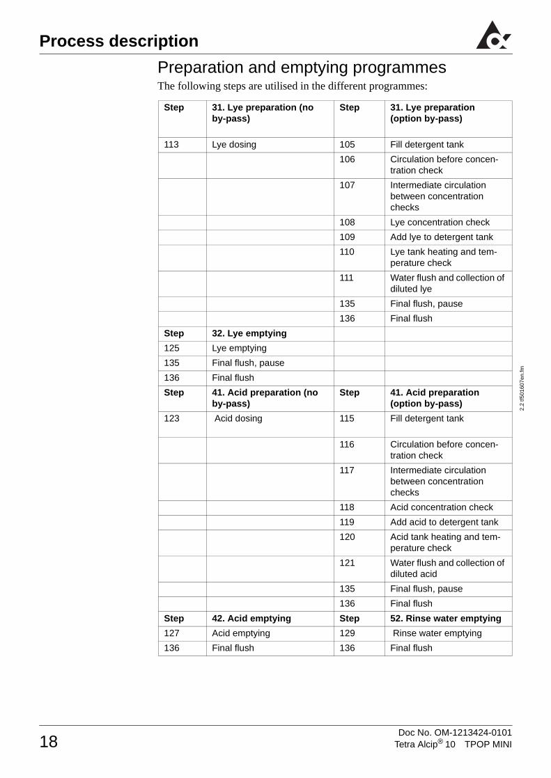
Preparation and emptying programmesThe following steps are utilised in the different programmes:
Step 31. Lye preparation (no by-pass)
Step 31. Lye preparation (option by-pass)
113 Lye dosing 105 Fill detergent tank
106 Circulation before concen-tration check
107 Intermediate circulation between concentration checks
108 Lye concentration check
109 Add lye to detergent tank
110 Lye tank heating and tem-perature check
111 Water flush and collection of diluted lye
135 Final flush, pause
136 Final flush
Step 32. Lye emptying
125 Lye emptying
135 Final flush, pause
136 Final flush
Step 41. Acid preparation (no by-pass)
Step 41. Acid preparation (option by-pass)
123 Acid dosing 115 Fill detergent tank
116 Circulation before concen-tration check
117 Intermediate circulation between concentration checks
118 Acid concentration check
119 Add acid to detergent tank
120 Acid tank heating and tem-perature check
121 Water flush and collection of diluted acid
135 Final flush, pause
136 Final flush
Step 42. Acid emptying Step 52. Rinse water emptying
127 Acid emptying 129 Rinse water emptying
136 Final flush 136 Final flush
18 Tetra Alcip® 10 TPOP MINIDoc No. OM-1213424-0101

Control panel 2.
2 tf5
0160
8en.
fm
Control panel
Denomination
1 Operator´s panel2 Conductivity instrument3 Emergency stop button4 Mains switch 5 Selector switch, remote control
1 = Tetra Alcip is operated from a remote system0 = Tetra Alcip is operated from the TPOP on the control panel
6 Cleaning indication lamp (green)steady light; CIP sequence runningflashing light; CIP sequence held
7 Alarm indication lamp (yellow):steady light; acknowledged alarmflashing light; unacknowledged alarm
�
�
�
�
�
�
Tetra Alcip 10
�
19Tetra Alcip® 10 TPOP MINIDoc No. OM-1213424-0101

Control panel
2.2
tf501
608e
n.fm
General rules for indication
Local/Remote controlLocal/Remote is selected by means of a key switch on the front of the control panel.
Local control means that the plant is operated from the TPOP. It is still possible to change pictures and view the application from the remote control unit, but it is not possible to operate the module
If the key is in remote position the module can be operated from the TPOP, a remote control system or remote I/O (ACO CIP).
Function symbolsFunctions available in the plant are indicated with a symbol. When the symbol is possible to select it appears as a “Push-button”.
A recessed symbol indicates the function has been selected.
Local control Remote control Remote I/O control
Selectable function Selected function
20 Tetra Alcip® 10 TPOP MINIDoc No. OM-1213424-0101

Control panel 2.
2 tf5
0160
8en.
fm
Common function symbols and indicationsThese function symbols indications are represented on several of the pictures
Restricted functionsThe access code push-button is available in the Overview picture. To get access to the restricted functions push the access code push-button and enter the correct access code with the numerical keys.
Following functions need access code:
• Manual step
• Regulator picture
• Editing parameters
Stop Start Confirm start/stop Leave the picture
Alarm symbol Step duration preset
Accumulated step timeDate and time Current step number
When entering correct code: green lightIf incorrect code is entered: blue light with a cross
The correct code is valid until a incorrect code is entered or maximum 20 minutes
21Tetra Alcip® 10 TPOP MINIDoc No. OM-1213424-0101
Control panel
2.2
tf501
608e
n.fm
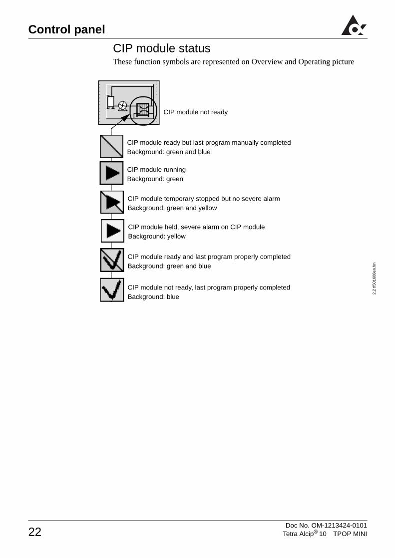
CIP module status These function symbols are represented on Overview and Operating picture
CIP module runningBackground: green
CIP module not ready, last program properly completed Background: blue
CIP module ready and last program properly completed Background: green and blue
CIP module temporary stopped but no severe alarmBackground: green and yellow
CIP module not ready
CIP module held, severe alarm on CIP moduleBackground: yellow
CIP module ready but last program manually completedBackground: green and blue
22 Tetra Alcip® 10 TPOP MINIDoc No. OM-1213424-0101

Control panel 2.
2 tf5
0160
8en.
fm
Control system menu tree
Overview picture
Station selection picture
Operation picture
Service picture Alarm log picture
Trend diagram picture
Parameter edit picture
Flowchart picture
Temperature controller picture
Parameter list picture
Language picture
23Tetra Alcip® 10 TPOP MINIDoc No. OM-1213424-0101

Control panel
2.2
tf501
608e
n.fm
Overview picture
1 Bring up the OPERATION PICTURE see page 26
2 Bring up the NUMERICAL KEY PICTURE for entering acces code, see page 36
3 Bring up the SERVICE PICTURE see page 33
4 Bring up the ALARM LOG PICTURE see page 30
1
3
2
4
24 Tetra Alcip® 10 TPOP MINIDoc No. OM-1213424-0101

Control panel 2.
2 tf5
0160
8en.
fm
Flowchart picture
1 Level indication symbol; low level in tank.
2 Valve symbol, green when active.
3 Displays temperature on return side; setpoint black field, measured value white field.
4 Displays temperature in the detergent tank; setpoint black field, measured value white field.
5 Displays conductivity on return side; setpoint black field, measured value white field.
6 Bring up the TEMPERATURE CONTROLLER PICTURE see page 27. Displays temperature on pressure side; setpoint black field, measured value white field.
4
3
6
1
2
5
25Tetra Alcip® 10 TPOP MINIDoc No. OM-1213424-0101

Control panel
2.2
tf501
608e
n.fm
Operation picture
1 Bring up the THE NUMERICAL KEY PICTURE see page 36 Display shows current CIP programme.
2 Bring up the NUMERICAL KEY PICTURE , see page 36. Display shows current CIP circuit.
3 Confirm chosen CIP circuit
4 Indicate CIP circuits ready for cleaning.
5 Indicate CIP circuits selected or running.
6 Bring up the CIP MODULE FLOWCHART PICTURE see page 22. See also CIP module status
7 Bring up the STATION SELECTION PICTURE, see page 34.
8 Manual step, used for forcing the cleaning cycle to step forward.
1
7
62
3
8
4
5
26 Tetra Alcip® 10 TPOP MINIDoc No. OM-1213424-0101

Control panel 2.
2 tf5
0160
8en.
fm
Temperature controller picture
1 Bar graph and numeric display of the input signal to the regulator.
2 Bar graph and numeric display of the setpoint for the regulator.
3 Bar graph and numeric display of the output signal of the regulator.
4 Auto mode
5 Manual mode
6 Bring up the NUMERICAL KEY PICTURE for change of setpoint setting see page 36.
7 Bring up the NUMERICAL KEY PICTURE for change of manual outputsee page 36.
8 Bring up the NUMERICAL KEY PICTURE for change of gain setting see page 36.
9 Gain setting for the utilized sequence step.
10 Bring up the NUMERICAL KEY PICTURE for change of integration time see page 36.
11 Integration time for the utilized sequence step.
� � �
�
�
�
�
�
�
��
27Tetra Alcip® 10 TPOP MINIDoc No. OM-1213424-0101

Control panel
2.2
tf501
608e
n.fm
Parameter edit picture
1 Bring up the PARAMETER LIST PICTURE see page 32.
2 Toggles up/down available circuits parameters.
3 Toggles up/down (3 step toggle) available circuits parameters.
4 Displays shows next parameter number/parameter value up/down.
5 Bring up the NUMERICAL KEY PICTURE ee page 36. . The displays shows parameter number/ parameter value.
6 Bring up the NUMERICAL KEY PICTURE see page 36. Display shows cur-rent CIP circuit number
�
�
�
�
�
�
28 Tetra Alcip® 10 TPOP MINIDoc No. OM-1213424-0101

Control panel 2.
2 tf5
0160
8en.
fm
Date and time picture
1 Selected pushbutton brings up the the NUMERICAL KEY PICTURE for setting of date and time for the PLC, see page 36.
2 Selected pushbutton brings up the the NUMERICAL KEY PICTURE for setting of date and time for the TPOP see page 36.
2
1
29Tetra Alcip® 10 TPOP MINIDoc No. OM-1213424-0101

Control panel
2.2
tf501
608e
n.fm
Alarm log picture
An active alarm is indicated by black text on yellow background togheter with a time stamp in the first column.
When the alarm is cleared, the text appears on white background with a time stamp in the second column.
When the alarm list is full the logged data is cleared according to the principle first-in-first-out.
1 Acknowledge alarm
1
30 Tetra Alcip® 10 TPOP MINIDoc No. OM-1213424-0101

Control panel 2.
2 tf5
0160
8en.
fm
Trend diagram picture
1 Trend curve for temperature (TE)
2 Trend curve for concentrate (QE)
�
�
31Tetra Alcip® 10 TPOP MINIDoc No. OM-1213424-0101

Control panel
2.2
tf501
608e
n.fm
Parameter list picture
1 Parameter number
2 Parameter value
�
�
32 Tetra Alcip® 10 TPOP MINIDoc No. OM-1213424-0101

Control panel 2.
2 tf5
0160
8en.
fm
Service picture
1 Bring up the PARAMETER EDIT PICTURE see page 28.
2 Bring up the TREND DIAGRAM PICTURE ee page 31.
3 Change brightness in picture
4 Bring up the DATE AND TIME PICTURE ee page 29.
5 Bring up the LANGUAGE PICTURE ee page 34.
��
�
��
33Tetra Alcip® 10 TPOP MINIDoc No. OM-1213424-0101

Control panel
2.2
tf501
608e
n.fm
Language picture
1 Selectable languages
2 Selected language
�
�
34 Tetra Alcip® 10 TPOP MINIDoc No. OM-1213424-0101

Control panel 2.
2 tf5
0160
8en.
fm
Station selection picture
31 Lye preparation
32 Lye emptying
41 Acid preparation
42 Acid emptying
52 Rinse water emptying
35Tetra Alcip® 10 TPOP MINIDoc No. OM-1213424-0101

Control panel
2.2
tf501
608e
n.fm
Numerical key picture
1 Selected parameter to be changed
2 Current value of selected parameter
3 If an entered value exceeds the min-max limits, there will be a flashing Indication: Max (Min) value exceeded.
4 Maximum permitted value of selected parameter
5 Entered value of selected parameter
6 Minimum permitted value of selected parameter
7 Back space
8 Enter new value
9 Leave the picture
1
2
3
4
56
7
8
9
36 Tetra Alcip® 10 TPOP MINIDoc No. OM-1213424-0101

Control panel 2.
2 tf5
0160
8en.
fm
List of alarmsCaution! Fault indication
Always investigate the cause of a fault indication. Otherwise you may endanger the equipment.
Alarms are divided into two categories as follows:
A Faults that will cause an alarm only. They are not critical but theoperator should investigate the cause.
B Faults that will cause a temporary stop. Rectify the fault.See section "Maintenance" in the technical manual (TeM) for trouble shooting chart.
Type Text in alarm menu Fault
A Temp fault return pipe Temperature fault return pipe
A Low conc. return pipe Low concentration return pipe
A High level circ. tank High level balance tank
A Too high conc.return pipe Too high concentration return pipe (only ACO)
B Motor fault M1 Feedback fault on pressure pump
B Motor fault M9 Feedback fault on disinfec-tion metering pump
B No flow in return pipe No flow in return pipe
B Low level in circ. tank Low level in balance tank
B Low level in lye tank Low level in lye tank
B Low level in acid tank Low level in acid tank
B Low airpressure Low pressure on air supply
B Emergency stop activated Emergency stop activated
B Temp. fault pressure side Temperature fault pressure side
B Host communication fault Communication fault with host computer
B Detergent tank not available Detergent tank not available (only ACO)
Detergent tank interlocked (only if several pressure lines)
B Circuit x not ready Circuit x not ready
B AFM x feedback fault Valve or boosterpump feed-back fault
37Tetra Alcip® 10 TPOP MINIDoc No. OM-1213424-0101

Control panel
2.2
tf501
608e
n.fm
This page intentionally left blank
38 Tetra Alcip® 10 TPOP MINIDoc No. OM-1213424-0101
Preparations 2.
2 tf5
0160
9en.
fm
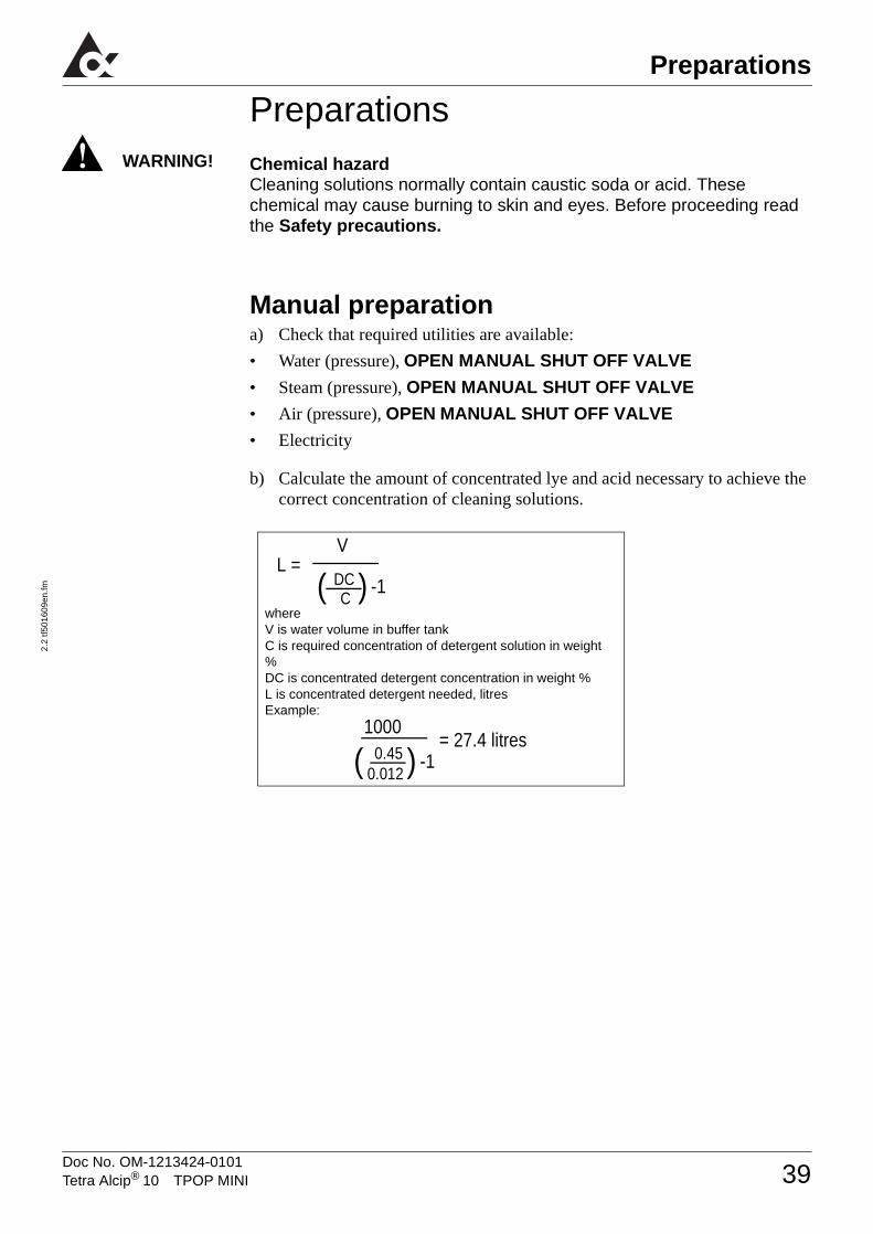
PreparationsChemical hazardCleaning solutions normally contain caustic soda or acid. These chemical may cause burning to skin and eyes. Before proceeding read the Safety precautions.
Manual preparationa) Check that required utilities are available:
• Water (pressure), OPEN MANUAL SHUT OFF VALVE
• Steam (pressure), OPEN MANUAL SHUT OFF VALVE
• Air (pressure), OPEN MANUAL SHUT OFF VALVE
• Electricity
b) Calculate the amount of concentrated lye and acid necessary to achieve the correct concentration of cleaning solutions.
WARNING!
whereV is water volume in buffer tankC is required concentration of detergent solution in weight %DC is concentrated detergent concentration in weight %L is concentrated detergent needed, litresExample:
L = DCC( )V
-1
0.450.012( )1000
-1= 27.4 litres
39Tetra Alcip® 10 TPOP MINIDoc No. OM-1213424-0101

Preparations
2.2
tf501
609e
n.fm
Preparation of lyea) Check that the MANUAL DRAIN VALVE V013 for the buffer tank is
CLOSED.
b) OPEN MANUAL WATER VALVE V023 to 50% to fill water into the lye buffer tank.
c) When the water level reaches the water inlet pipe: ADD gently the concentrated lye into the buffer tank via the man hole.
d) When the buffer tank is filled to required level (water + lye): CLOSE MANUAL WATER VALVE V023.
Preparation of acid a) Check that the MANUAL DRAIN VALVE V013 for the buffer tank is
CLOSED.
b) OPEN MANUAL WATER VALVE (V022) to 50% to fill water into the acid buffer tank.
c) When the water level reaches the water inlet pipe: ADD gently the concentrated acid into the buffer tank via the man hole.
d) When the buffer tank is filled to required level (water + acid): CLOSE THE MANUAL WATER VALVE (V022).
40 Tetra Alcip® 10 TPOP MINIDoc No. OM-1213424-0101

Preparations 2.
2 tf5
0160
9en.
fm
Preparation with metering pump
a) Check the capacity of the metering pumps
b) Calculate required dosing times
c) Update parameter (see section Commissioning in Technical Manual)
– 1 FOR LYE
– 13 FOR ACID
d) Check the level for concentrated lye and acid. Adjust if necessary.
Preparation of lye (no by-pass valve)a) Check that the MANUAL DRAIN VALVE V013 for the buffer tank is
CLOSED.
b) OPEN MANUAL WATER VALVE V023 to 50% to fill water into the lye buffer tank.
c) Display the STATION PROGRAM picture. see page 47 and start the desired station program
Preparation of acid (no by-pass valve)a) Check that the MANUAL DRAIN VALVE V013 for the buffer tank is
CLOSED.
b) Open MANUAL WATER VALVE V022 to 50% to fill water into the acid buffer tank.
c) Display the STATION PROGRAM picture. see page 47 and start the desired station program.
d) When the buffer tank is filled to required level, CLOSE MANUAL WATER VALVE
– V023 (If lye preparation)
– V022 (If acid preparation)
whereL is concentrated detergent needed, litresCS is capacity of metering pump, litres/secondS is required metering pump run time, seconds to make a complete preparartionExample:
seconds
L CS-------- S =
27 4,0,055--------------- 498=
41Tetra Alcip® 10 TPOP MINIDoc No. OM-1213424-0101

Preparations
2.2
tf501
609e
n.fm
Preparation using the by-passa) Display the STATION PROGRAM picture. see page 47 and start the
desired station program.
b) The detergent tank is filled to LSH with water , fresh water is taken from the circulation tank. The steam valve is activated and the steam starts to heat up the cleaning solution.
c) Detergent tank level reach LSH.
d) Circulation of detergent tank starts and continues for a preset time (parameter).
e) Intermediate circulation of detergent tank starts and continues for a preset time (parameter).
f) Check of concentration starts.
– If concentration is below setpoint (parameter) the program continues on step g) .
– If concentration is correct the program continues on step h).
g) Filling of remaining concentrated detergent starts.
– Metering pump for concentrated detergent is activated for a (by the program) calculated time.
– When the time has elapsed the program continues on step e).
h) Check of temperature starts.
– When the temperature reaches setpoint (parameter), the steam valve closes.
i) Water is flushed into the system to sort out and collect the cleaning solution in the pipes to the detergent tank.
j) Water is flushed to drain for a preset time (parameter).
42 Tetra Alcip® 10 TPOP MINIDoc No. OM-1213424-0101

Preparations 2.
2 tf5
0160
9en.
fm
M M2
TE1
TE3
Water Water
Lye Acid
WaterLye tank Acid tank Rinse water tank
Balance tank
CIP pressure
CIP return
M M2
TE1
TE3
Water Water
Lye Acid
WaterLye tank Acid tank Rinse water tank
Balance tank
CIP pressure
CIP return
Flow during preparation, filling of lye tank
Flow during preparation, lye circulation
43Tetra Alcip® 10 TPOP MINIDoc No. OM-1213424-0101

Preparations
2.2
tf501
609e
n.fm
This page intentionally left blank
44 Tetra Alcip® 10 TPOP MINIDoc No. OM-1213424-0101

2.
2tf5
0161
0en.
fm
Initial start of cleaning1a) Display the OPERATION PICTURE.
Select CIP circuit program
b) Select PRG PUSH-BUTTON to display the numerical key picture
c) Use the numerical key to enter the desired CIP circuit program, see chapter “Control panel”.
Select circuit number
d) Select CIR PUSH-BUTTON to display the numerical key picture
e) Use the numerical key to enter the desired CIP circuit, see chapter “Control panel”.
f) Select push-button to CONFIRM.
– If the confirmation is valid the selected circuit will be marked with X in the “Circuit display”
Circuit display
Tetra Alcip® 10 TPOP MINI Doc No. OM-1213424-0101
Operation
45

Operation
2.2t
f501
610e
n.fm
�
�g) START AND CONFIRM the program
with the “Common function symbols”
Cleaning of package machine (optional)1If cleaning of packaging machines it is possible to select more than one CIP circuit.
To reset a selection, select the circuit again
• Communication: 4 packaging machines; circuit numbers 9-14
Confirm the circuit selection, select cleaning program and start the cleaning as described above.
46 Tetra Alcip® 10 TPOP MINIDoc No. OM-1213424-0101

Operation 2.
2tf5
0161
0en.
fm
Initial start of stations programs1a) Display the STATION PROGRAM
picture.
Note!The initial start of station programs must be done from the station program picture. When this is done it is possible to stop and restart the station program from other menus.
b) Select the PUSH-BUTTON that represent the desired station program and the display turns yellow.
c) START AND CONFIRM the program with the “Common function symbols”
Stepping of cleaning cycle1Select the MANUAL STEP followed by CONFIRM to step the cleaning cycle forward
Note!Manual stepping can be done only when CIP is running and if valid acess code is entered.
47Tetra Alcip® 10 TPOP MINIDoc No. OM-1213424-0101

Operation
2.2t
f501
610e
n.fm
Drain of tankDrain of a tank can be done as long as there is no cleaning started.
If the module is not equipped with by-pass valve; connect the circuit to a neutralizing unit, drain etc.
Note!The initial start of station programs must be done from the station program picture. When this is done it is possible to stop and restart the station program from other menus.
a) Select the PUSH-BUTTON for the desired station program.
– The button will change color.
b) Select START push-button.
c) Select CONFIRM START/STOP push-button.
48 Tetra Alcip® 10 TPOP MINIDoc No. OM-1213424-0101

Cleaning2.
2 tf5
0131
4en.
fm
CleaningTo achieve the best possible performance of the equipment it is essential to keep it clean and tidy.
Clean the buffer tanks when changing cleaning solution:
Do as follows:
a) Perform a Drain of the tank, see section Operation.
b) Fill a small amount of water. Use a rubber hose.
c) Scrub the tank inside with a broom.
d) Open the manual drain valves (V013 for lye and V012 for acid) to drain the tank.
e) Flush the tank with water. Use a rubber hose, continue until no residues remains.
f) Close the manual drain valves (V013 and V012).
• Clean the panel once a week with a cloth.
• Clean remaining equipment at regular intervals.
Chemical hazardCleaning solution contains caustic soda (NaOH) or nitric acid (HNO3). This chemical may cause severe burning to skin and eyes. Use protective clothes, goggles and gloves during handling. If exposed - wash with water for at least 15 minutes. Seek medical assistance. Follow the instructions given by the supplier.
WARNING!
49Tetra Alcip® 10 TPOP MINIDoc No. OM-1213424-0101

Cleaning
2.2
tf501
314e
n.fm
This page intentionally left blank
50 Tetra Alcip® 10 TPOP MINIDoc No. OM-1213424-0101

2.
2tf5
0131
5en.
fm
Inspection/change of parameter values1a) Display the PARAMETER EDIT
PICTURE for the appropriate module.
CAUTION!Change of valuesA change of value will change the machines way of working. This operation needs access code
Note!For parameter list, see section “Commissioning” in Technical Manual (TeM).
Tetra Alcip® 10 TPOP MINI Doc No. OM-1213424-0101
Settings
51

Settings
2.2t
f501
315e
n.fm
Change parameter number
2a) Toggle the ARROWS until the right
parameter number to inspect/change is displayed or select the P PUSH-BUTTON to display the numerical keys picture and enter the desired parameter number
b) To change value continue according to Change parameter value
3
Change parameter value
a) Select V PUSH-BUTTON to display the numerical keys picture
b) Use the numerical key to enter the new parameter value see chapter “Control panel”.
Note!If no value is given the old value is kept unchanged.
parameter number
1 step toggle 3 step toggle
Next parameter number toggling down
Next parameter number toggling up
52 Tetra Alcip® 10 TPOP MINIDoc No. OM-1213424-0101

Settings 2.
2tf5
0131
5en.
fm
Inspection/change of controllers4a) Display the CONTROLLER
PICTURE.
Note!In the controller menu change of settings for test purpose is possible. When leaving the controller menu the settings are reset to values used when entering the menu.
Final setting is selected in a parameter, see section “Commissioning” in Technical manual (TeM).
5
Change of gain, TI and setpoint
a) Select the PUSH-BUTTON symbolizing desired controller
b) Use the numerical key to enter new value see chapter “Control panel”.
53Tetra Alcip® 10 TPOP MINIDoc No. OM-1213424-0101

Settings
2.2t
f501
315e
n.fm
6
Change of output
a) Select MANUAL MODE PUSHBUTTON for turning the controller manually off
b) Select MAN OUT PUSH-BUTTON to display the numerical keys picture
c) Use the numerical key to enter the new output see chapter “Control panel”.
a) Select AUTO MODE PUSHBUTTON for turning the controller manually on.
54 Tetra Alcip® 10 TPOP MINIDoc No. OM-1213424-0101


Ref text to introduction