om0298r1i-mobixray tx-mlp - rdlg (100505)
TRANSCRIPT

7/21/2019 Om0298r1i-Mobixray TX-mlp - Rdlg (100505)
http://slidepdf.com/reader/full/om0298r1i-mobixray-tx-mlp-rdlg-100505 1/68
Technical Publication
OM-0298R1
OperationMobile X-ray Unit
TRANSPORTIX TX-16-MLP / TX-20-MLP / TX-32-MLP

7/21/2019 Om0298r1i-Mobixray TX-mlp - Rdlg (100505)
http://slidepdf.com/reader/full/om0298r1i-mobixray-tx-mlp-rdlg-100505 2/68
This product bears a CE marking in accordance with the provisions of the 93/42/EEC MDD dated June 14, 1993.
Este producto ostenta una marca CE de acuerdo con las disposiciones de la Directiva 93/42/CEE del 14 de Junio de 1993 sobre Productos Médicos.
Ce produit porte la marque CE de conformité aux réglements de la Directive 93/42/CEE du 14 juin 1993 relative aux Produits médicaux.
Manufactured by:
Fabricado por:
SEDECAL
Sociedad Española de Electromedicina y Calidad S.A.
Pelaya, 9 -- 13. Polígono Industrial “Río de Janeiro”28110 Algete, Madrid -- España (Spain)
Phone: +34 916 280 544 Fax: +34 902 190 385 www.sedecal.com
The information comprised in this manual applies to the following equipments
La información contenida en este manual se aplica a los siguientes equipos
L’information contenue dans ce manuel est appliquée aux équipements suivants
TX-16-MLP, TX-20-MLP,TX-32-MLP
7/21/2019 Om0298r1i-Mobixray TX-mlp - Rdlg (100505)
http://slidepdf.com/reader/full/om0298r1i-mobixray-tx-mlp-rdlg-100505 3/68
¡ IMPORTANTE ! ... Protección ante los rayos-X
LOS EQUIPOS DE RAYOS-X SON PELIGROSOS PARA EL PACIENTE Y EL OPERADOR
A MENOS QUE LAS MEDIDAS DE PROTECCION SEAN ESTRICTAMENTE OBSERVADAS
Si el equipo de rayos-X no se usa adecuadamente, puede causar lesiones. Por este motivo, las instrucciones
aquí incluidas se deben leer y comprender en su totalidad antes de intentar poner el equipo en funcionamiento.
Estaremos gustosos de asistir y cooperar en poner el equipo en marcha.
Aunque el equipo está construido según las normas de seguridad más estrictas y presenta un alto grado de protección contra las
radiaciones-X, ningún diseño practico puede ofrecer una protección completa. Tampoco ningún diseño practico puede obligar al operador
a tomar las precauciones adecuadas para prevenir la posibilidad de que cualquier persona de manera descuidada, poco sensata o
ignorante, se exponga a radiaciones directas o indirectas.
Es importante que cualquier persona relacionada con radiaciones-X esté debidamente entrenada y tome las medidas adecuadas para
asegurar la protección contra posibles lesiones.
El fabricante asume que todo operador y personal de servicio autorizado para manejar, instalar, calibrar o mantener este equipo, es
consciente del peligro que conlleva la exposición excesiva a las radiaciones-X, está suficientemente entrenado y posee los conocimiento
necesarios para ello. Por lo tanto, el equipo aquí descrito se vende entendiendo que el fabricante, sus agentes y representantes
no tienen ninguna responsabilidad en caso de lesiones o daños que puedan resultar de la exposición a dichas radiaciones.
Existen diversos materiales y dispositivos protectores, cuyo uso es recomendable.
IMPORTANT ! ... X-ray Protection
X-RAY EQUIPMENT IS DANGEROUS TO BOTH PATIENT AND OPERATOR
UNLESS MEASURES OF PROTECTION ARE STRICTLY OBSERVED
X-ray equipment if not properly used may cause injury. Accordingly, the instructions herein should be thoroughly
read and understood before attempting to place this equipment in operation. We will be glad to assist and
cooperate in placing this equipment in use.
Although this apparatus is built to the highest safety standards and incorporates a high degree of protection against X-radiation other
than the useful beam, no practical design of equipment can provide complete protection. Nor can any practical design compel the
operator to take adequate precautions to prevent the possibility of any persons carelessly, unwisely, or unknowingly exposing themselvesor others to X-radiation.
It is important that everyone working with X-radiation be properly trained and take adequate steps to insure protection against injury.
The manufacturer assumes that all operator and service personnel authorized to use, install, calibrate and maintain this equipment
is cognizant of the danger of excessive exposure to X-radiation, is sufficiently trained and has the required knowledges for it. The
equipment herein described is sold with the understanding that the manufacturer, its agents, and representatives are not liable for
injury or damage which may result from exposure to X-radiation.
Various protective material and devices are available. It is recommended that such materials and devices be used.
IMPORTANT ! ... Protection contre les rayons-X
L’EQUIPEMENT RAYONS-X EST DANGEREUX A LA FOIS POUR LE PATIENT ET POUR L’OPERATEURA MOINS D’OBSERVER STRICTEMENT LES CONSIGNES DE PROTECTION
L’équipement à rayons-X peut provoquer des blessures s’il n’est pas correctement utilisé. En conséquence,
les instructions de ce manuel doivent être lues attentivement et bien assimilées avant de tenter de mettre en
route ce matériel. Nous serons heureux de vous assister et de coopérer à l’installation de ce matériel.
Bien que cet équipement soit construit selon les normes de construction les plus sévères et qu’il comporte un haut degré de protection
contre le rayonnement-X en dehors du rayon utile, aucune conception n’apporte une protection totale. De même qu’aucune conception
ne peut obliger l’opérateur à prendre les précautions adéquates afin d’éviter que toute personne ne s’expose ou n’expose les autres
au rayonnement sans précaution, de façon imprudente et inconsciente.
Il est important que toutes les personnes travaillant avec le rayonnement-X soit correctement formées et prennent les mesures adéquates
afin de se protéger contre toute blessure.
Le constructeur suppose quetous les utilisateurs et le personneld’entretienautorisé à utiliser, installer, calibrer et entretenir cetéquipement
est conscient du danger de l’exposition excessive au rayonnement-X, est suffisamment formé et possède les connaissances nécessaires
pour cela. L’équipement décrit dans le présent manuel est vendu sous réserve que le fabricant, ses agents et représentants ne soient
pas tenus pour responsables des blessures ou dommages qui pourraient résulter d’une exposition aux rayons-X.
Plusieurs matériels de protection et systèmes sont disponibles. L’utilisation de ces matériels et systèmes de protection est recommandée.

7/21/2019 Om0298r1i-Mobixray TX-mlp - Rdlg (100505)
http://slidepdf.com/reader/full/om0298r1i-mobixray-tx-mlp-rdlg-100505 4/68
DECLARACION AMBIENTALSOBRE LA VIDA UTIL DEL EQUIPO O SISTEMA
Este equipo o sistema contiene componentes y materiales peligrosos para el medioambiente (talescomo tarjetas de circuito impreso, componentes electrónicos, aceite dieléctrico usado, plomo,baterías, etc), los cuales se consideran y son residuos peligrosos al finalizar la vida útil del equipo osistema, según establecen las normas internacionales, nacionales y locales.
El fabricante recomienda que al finalizar la vida útil de equipo o sistema, se contacte con unrepresentanteautorizado delfabricante o con un gestor autorizadode residuos para la retirada de esteequipo o sistema.
ENVIRONMENTAL STATEMENT
ON THE LIFE CYCLE OF THE EQUIPMENT OR SYSTEM
This equipment or system contains environmentally dangerous components and materials (such asPCB‘s, electronic components, used dielectric oil, lead, batteries etc.) which, once the life-cycle of the
equipment or system comes to an end, becomes dangerous and need to be considered as harmfulwaste according to the international, domestic and local regulations.
The manufacturer recommends to contact an authorized representative of the manufacturer or anauthorized waste management company once the life-cycle of the equipment or system comes to anend to remove this equipment or system.
DECLARATION D’ENVIRONNEMENT
SUR LA VIE UTILE DE L’EQUIPEMENT OU SYSTEME
Cet équipement ou système contient des composants et matériaux dangereux pour l’environnement(ex: électroniques cartes, composants électroniques, huile diélectrique usée, plomb, batteries, etc.),lesquels sont considérés comme résidus dangereux en cycle terminal de vie d’un équipement ousystème, en accord avec les normes internationales, nationales et locales en vigueur.
Le fabricant recommande une fois le cycle terminal de l’équipement ou système atteint, de contacterun représentant autorisé du fabricant ou les autorités compétentes en la matière afin d’organiser etde gérer le recyclage adéquat de cet équipement ou appareil.

7/21/2019 Om0298r1i-Mobixray TX-mlp - Rdlg (100505)
http://slidepdf.com/reader/full/om0298r1i-mobixray-tx-mlp-rdlg-100505 5/68
Mobile X-ray Unit
Operation
OM-0298R1
REVISION HISTORY
REVISION DATE REASON FOR CHANGE
0 OCT 04, 2006 First Edition
1 APR 29, 2010 Removed Line Selector Board
This Document is the original English version, edited and supplied by the manufacturer.
The Revision state of this Document is indicated in the code number shown at the bottom of this page.
ADVISORY SYMBOLS
The following advisory symbols will be used throughout this manual. Theirapplication and meaning are described below.
DANGERS ADVISE OF CONDITIONS OR SITUATIONS THAT
IF NOT HEEDED OR AVOIDED WILL CAUSE SERIOUS
PERSONAL INJURY OR DEATH.
ADVISE OF CONDITIONS OR SITUATIONS THAT IF NOTHEEDEDOR AVOIDED COULD CAUSE SERIOUS PERSONALINJURY, OR CATASTROPHIC DAMAGE OF EQUIPMENT ORDATA.
Advise of conditions or situations that if not heeded or
avoided could cause personal injury or damage to equipment
or data.
Note . Alert readers to pertinent facts and conditions. Notes represent
information that is important to know but which do not necessarily
relate to possible injury or damage to equipment.

7/21/2019 Om0298r1i-Mobixray TX-mlp - Rdlg (100505)
http://slidepdf.com/reader/full/om0298r1i-mobixray-tx-mlp-rdlg-100505 6/68
Mobile X-ray Unit
Operation
OM-0298R1
SAFETY SYMBOLS
The following safety symbols will be used in the equipment.Their meanings are described below.
Attention, consult accompanying documents.
Ionizing radiation.
Type B equipment.
Dangerous voltage.
Ground.
This symbol indicates that the waste of electrical andelectronic equipment must not be disposed as unsortedmunicipal waste and must be collected separately. Pleasecontact an authorized representative of the manufacturer oran authorized waste management company for informationconcerning the decommissioning of your equipment.

7/21/2019 Om0298r1i-Mobixray TX-mlp - Rdlg (100505)
http://slidepdf.com/reader/full/om0298r1i-mobixray-tx-mlp-rdlg-100505 7/68
Mobile X-ray Unit
Operation
OM-0298R1 i
TABLE OF CONTENTS
Section Page
1 INTRODUCTION 1. . . . . . . . . . . . . . . . . . . . . . . . . . . . . . . . . . . . . . . . . . . . . . . . . . . . . . . . .
1.1 General Features 3. . . . . . . . . . . . . . . . . . . . . . . . . . . . . . . . . . . . . . . . . . . . . . . . . . .
1.2 Product Identification 5. . . . . . . . . . . . . . . . . . . . . . . . . . . . . . . . . . . . . . . . . . . . . . . .
1.3 Certifications 6. . . . . . . . . . . . . . . . . . . . . . . . . . . . . . . . . . . . . . . . . . . . . . . . . . . . . . .
1.4 Classification 6. . . . . . . . . . . . . . . . . . . . . . . . . . . . . . . . . . . . . . . . . . . . . . . . . . . . . . .
2 SAFETY 7. . . . . . . . . . . . . . . . . . . . . . . . . . . . . . . . . . . . . . . . . . . . . . . . . . . . . . . . . . . . . . . .
2.1 General 7. . . . . . . . . . . . . . . . . . . . . . . . . . . . . . . . . . . . . . . . . . . . . . . . . . . . . . . . . . .
2.2 Responsibilities 8. . . . . . . . . . . . . . . . . . . . . . . . . . . . . . . . . . . . . . . . . . . . . . . . . . . . .
2.3 Maximum Permissible Dose (MPD) 9. . . . . . . . . . . . . . . . . . . . . . . . . . . . . . . . . . .
2.4 Radiation Protection 10. . . . . . . . . . . . . . . . . . . . . . . . . . . . . . . . . . . . . . . . . . . . . . . . .
2.5 Monitoring of Personnel 11. . . . . . . . . . . . . . . . . . . . . . . . . . . . . . . . . . . . . . . . . . . . .
2.6 Protection against Electric Shock Hazards 11. . . . . . . . . . . . . . . . . . . . . . . . . . . . .
2.7 Protection against Hazards from Unwanted or Excessive Radiation 11. . . . . . . .
2.8 Designated Significant Zones of Occupancy 12. . . . . . . . . . . . . . . . . . . . . . . . . . . .
2.9 Electromagnetic Compatibility (EMC) 14. . . . . . . . . . . . . . . . . . . . . . . . . . . . . . . . . .
3 GENERAL AND MOTION CONTROLS 19. . . . . . . . . . . . . . . . . . . . . . . . . . . . . . . . . . . . .
3.1 Mains connection and Line Circuit Breaker 20. . . . . . . . . . . . . . . . . . . . . . . . . . . . .
3.2 Generator Control Console 20. . . . . . . . . . . . . . . . . . . . . . . . . . . . . . . . . . . . . . . . . . .
3.3 Front Panel 21. . . . . . . . . . . . . . . . . . . . . . . . . . . . . . . . . . . . . . . . . . . . . . . . . . . . . . . .
3.4 Bucky / AEC External Connection (Optional) 22. . . . . . . . . . . . . . . . . . . . . . . . . . .
3.5 X-ray Handswitch 22. . . . . . . . . . . . . . . . . . . . . . . . . . . . . . . . . . . . . . . . . . . . . . . . . . .
3.6 Infrared Remote Control (optional) 23. . . . . . . . . . . . . . . . . . . . . . . . . . . . . . . . . . . .
3.6.1 Operation 24. . . . . . . . . . . . . . . . . . . . . . . . . . . . . . . . . . . . . . . . . . . . . . . . . . .
3.6.2 The “Remote Finder” Device 24. . . . . . . . . . . . . . . . . . . . . . . . . . . . . . . . . . .

7/21/2019 Om0298r1i-Mobixray TX-mlp - Rdlg (100505)
http://slidepdf.com/reader/full/om0298r1i-mobixray-tx-mlp-rdlg-100505 8/68
Mobile X-ray Unit
Operation
OM-0298R1 ii
Section Page
3.7 Motion Controls 25. . . . . . . . . . . . . . . . . . . . . . . . . . . . . . . . . . . . . . . . . . . . . . . . . . . .
3.7.1 Control for Arm Positioning 25. . . . . . . . . . . . . . . . . . . . . . . . . . . . . . . . . . . .
3.7.2 Parking Position 27. . . . . . . . . . . . . . . . . . . . . . . . . . . . . . . . . . . . . . . . . . . . .
3.7.3 Displacement Controls 28. . . . . . . . . . . . . . . . . . . . . . . . . . . . . . . . . . . . . . . .
3.8 Collimator Controls 29. . . . . . . . . . . . . . . . . . . . . . . . . . . . . . . . . . . . . . . . . . . . . . . . . .
3.9 Dosimetry (optional) 29. . . . . . . . . . . . . . . . . . . . . . . . . . . . . . . . . . . . . . . . . . . . . . . . .
4 CONTROL CONSOLE 31. . . . . . . . . . . . . . . . . . . . . . . . . . . . . . . . . . . . . . . . . . . . . . . . . . . .
4.1 Power ON / OFF 32. . . . . . . . . . . . . . . . . . . . . . . . . . . . . . . . . . . . . . . . . . . . . . . . . . .
4.2 Exposure Indicators 32. . . . . . . . . . . . . . . . . . . . . . . . . . . . . . . . . . . . . . . . . . . . . . . . .
4.3 Workstation 32. . . . . . . . . . . . . . . . . . . . . . . . . . . . . . . . . . . . . . . . . . . . . . . . . . . . . . . .
4.4 Focal Spot Indicators 33. . . . . . . . . . . . . . . . . . . . . . . . . . . . . . . . . . . . . . . . . . . . . . . .
4.5 Radiographic Parameters 34. . . . . . . . . . . . . . . . . . . . . . . . . . . . . . . . . . . . . . . . . . . .
4.6 Automatic Exposure Control (AEC) (optional) 36. . . . . . . . . . . . . . . . . . . . . . . . . .
4.7 Anatomical Programmer (APR) 37. . . . . . . . . . . . . . . . . . . . . . . . . . . . . . . . . . . . . . .
4.8 Heat Units 46. . . . . . . . . . . . . . . . . . . . . . . . . . . . . . . . . . . . . . . . . . . . . . . . . . . . . . . . .
4.9 Exposure Counters 46. . . . . . . . . . . . . . . . . . . . . . . . . . . . . . . . . . . . . . . . . . . . . . . . .
4.10 Self-diagnosis Indicators 46. . . . . . . . . . . . . . . . . . . . . . . . . . . . . . . . . . . . . . . . . . . . .
4.11 Error Codes 47. . . . . . . . . . . . . . . . . . . . . . . . . . . . . . . . . . . . . . . . . . . . . . . . . . . . . . . .
5 OPERATING SEQUENCES 51. . . . . . . . . . . . . . . . . . . . . . . . . . . . . . . . . . . . . . . . . . . . . . .
5.1 Start-up Routine 51. . . . . . . . . . . . . . . . . . . . . . . . . . . . . . . . . . . . . . . . . . . . . . . . . . . .
5.2 X-ray Tube Warm-up Procedure 51. . . . . . . . . . . . . . . . . . . . . . . . . . . . . . . . . . . . . .
5.3 Radiographic Operation 52. . . . . . . . . . . . . . . . . . . . . . . . . . . . . . . . . . . . . . . . . . . . .5.4 AEC Operation 53. . . . . . . . . . . . . . . . . . . . . . . . . . . . . . . . . . . . . . . . . . . . . . . . . . . . .
5.5 APR Operation 54. . . . . . . . . . . . . . . . . . . . . . . . . . . . . . . . . . . . . . . . . . . . . . . . . . . .
6 PERIODIC MAINTENANCE 55. . . . . . . . . . . . . . . . . . . . . . . . . . . . . . . . . . . . . . . . . . . . . .
6.1 Operator Tasks 55. . . . . . . . . . . . . . . . . . . . . . . . . . . . . . . . . . . . . . . . . . . . . . . . . . . . .
6.2 Service Tasks 56. . . . . . . . . . . . . . . . . . . . . . . . . . . . . . . . . . . . . . . . . . . . . . . . . . . . . .
7 TECHNICAL SPECIFICATIONS 57. . . . . . . . . . . . . . . . . . . . . . . . . . . . . . . . . . . . . . . . . . .

7/21/2019 Om0298r1i-Mobixray TX-mlp - Rdlg (100505)
http://slidepdf.com/reader/full/om0298r1i-mobixray-tx-mlp-rdlg-100505 9/68
Mobile X-ray Unit
Operation
OM-0298R1 1
SECTION 1 INTRODUCTION
This manual contains all the information necessary to understand and operatethe Mobile X-ray Unit. It provides a general description, safety and regulatoryinformation, operation instructions and specifications concerning theequipment.
This equipment is designed for general radiography. It provides all theadvantages of high frequency waveform Generators including lower patientdose, shorter exposure times as well as greater accuracy and consistency.
The Generator is controlled by multiple microprocessors providing increasedexposure consistency, efficient operation and extended Tube life. A high levelof self-diagnostics greatly increases serviceability and reduces down time.
All functions, displays and controls are logically arranged, easily accessible andidentified to prevent confusion. Technique factors and functions are selectedon the Control Console.
Illustration 1-1Mobile X-ray Unit

7/21/2019 Om0298r1i-Mobixray TX-mlp - Rdlg (100505)
http://slidepdf.com/reader/full/om0298r1i-mobixray-tx-mlp-rdlg-100505 10/68
Mobile X-ray Unit
Operation
OM-0298R1 2
The Unit consists of the following fundamental parts:
• Control Console, operator controls and displays for radiographicoperations and general functions. The Console is designed for easeoperation.
• Generator that includes:
G Power Module, which contains the Power and Controlcomponents.
G High Voltage Transformer .
G Capacitor Module, with the Energy Storage Capacitors and thecharge / control components.
• Tube-Collimator Assembly, that comprises the X-ray Tube and theCollimator.
• Column and Arm, holding the Tube-Collimator Assembly and allows itspositioning.
• X-ray Cassette Basket for cassettes of 35 x 43 cm or smaller sizes.

7/21/2019 Om0298r1i-Mobixray TX-mlp - Rdlg (100505)
http://slidepdf.com/reader/full/om0298r1i-mobixray-tx-mlp-rdlg-100505 11/68
Mobile X-ray Unit
Operation
OM-0298R1 3
1.1 GENERAL FEATURES
The main features of this equipment are:
• A solid and ergonomic design. Easy operation, security and precision ofall positioning movements relative to the position of the patient.
• Constant potential high frequency.
• Tube-Collimator Assembly rotation in relation to its transverse axis(¦90o) and horizontal axis (205o). Collimator rotation in relation to itsvertical axis (¦90o).
• ThreepointcontrolbyselectingkVp,mAandExposureTime,ortwopointcontrol by selecting kVp and mAs, or one point control by selecting kVpwith AEC operations.
• Anatomical Programmer (APR), for six patient sizes (three adults andthree children), with pre-programmed anatomical views for automatic
selection. The operator may introduce modifications manually in all theoriginal APR techniques and store them for later use.
• Automatic Exposure Control (AEC) (optional), which accommodatesmost popular exposure detectors.
• Direct connection for one Bucky / Ion Chamber (optional).
• X-ray Handswitch for making Radiographic X-ray exposures.
• Remote infrared X-ray Handswitch (optional).
• Manual Collimation.
• Heat Unit storage for the X-ray Tube, even after turning On / Off theequipment.
7/21/2019 Om0298r1i-Mobixray TX-mlp - Rdlg (100505)
http://slidepdf.com/reader/full/om0298r1i-mobixray-tx-mlp-rdlg-100505 12/68
Mobile X-ray Unit
Operation
OM-0298R1 4
• Tube protection circuitry prolongs Tube life and increases systemperformance.
• Equipped with closed loop control of X-ray Tube current, kVp andfilaments, which minimize potential errors and the need forreadjustments.
• Standard electrical outlet operation with single-phase line at 100 / 110 / 120 / 208 / 230 / 240 ¦10% VAC.
• Under normal operating conditions, the Storage Capacitors are kept at
an optimum charge level by the Capacitor Charger which controls thelevel and performs charges periodically.
The Capacitors Module undergoes the charge-up process in thefollowing conditions (a whistle sounds during charge-up inside theGenerator).
G When the Unit is turned ON and makes the first charge. The totalcharge time depends on both the input voltage of mains where theUnit is plugged-in and the initial charge level of the Capacitors(maximum 4 seconds for a line of 230 VAC with selection of 16 Ain the Generator; or maximum 40 seconds for a line of 110 VAC
with selection of 8 A in the Generator).
G During X-ray exposures.
G During periodic charges with the Generator turned ON (instand-by), approximately every 150 seconds.
The mAs value is limitedand dependson the selected kVp and mA
values.Higher mAs values are obtained when selecting lower kVp
and mA values.
Note .

7/21/2019 Om0298r1i-Mobixray TX-mlp - Rdlg (100505)
http://slidepdf.com/reader/full/om0298r1i-mobixray-tx-mlp-rdlg-100505 13/68
Mobile X-ray Unit
Operation
OM-0298R1 5
1.2 PRODUCT IDENTIFICATION
To provide manufacturer and product information, each major item in theequipment has identification labels attached. The labels contain the followinginformation:
• Product
• Model.
• Volts (V), Line Phases, Frequency (Hz), and Power (kVA, kW).
• Date of manufacture.
•
Serial number.• Manufacturer.
• Place of manufacture.
• Certification

7/21/2019 Om0298r1i-Mobixray TX-mlp - Rdlg (100505)
http://slidepdf.com/reader/full/om0298r1i-mobixray-tx-mlp-rdlg-100505 14/68
Mobile X-ray Unit
Operation
OM-0298R16
1.3 CERTIFICATIONS
The Mobile X-ray Unit covered by this Operation Manual is authorized to bemarked with CE MARKING in accordance with the provisions of the CouncilDirective 93 / 42 / EEC concerning Medical Devices.
1.4 CLASSIFICATION
The Mobile X-ray Unit covered by this Operation Manual is classified as:
• Protection against Electric Shock : Class I -- Type B applied parts.
• Protection against Harmful Ingress of Water : Ordinary.
• Degree of Safety in the presence of Flammable Anesthetics Mixture with
air or with oxygen or with nitrous oxide: Not suitable for use in thepresence of Flammable Anesthetics Mixture with air or with oxygen orwith nitrous oxide.
• Mode of Operation: Continuous operation with intermittent loading.

7/21/2019 Om0298r1i-Mobixray TX-mlp - Rdlg (100505)
http://slidepdf.com/reader/full/om0298r1i-mobixray-tx-mlp-rdlg-100505 15/68
Mobile X-ray Unit
Operation
OM-0298R1 7
SECTION 2 SAFETY
2.1 GENERAL
Keep this Operating Manual with the equipment at all times and periodicallyreview the Operating and Safety instructions.
For a continuous and safe use of this equipment follow the
instructions in this Operating Manual. Study this manual
carefully before using the equipment and keep it at hand for
quick reference.
THEEQUIPMENT DESCRIBEDIN THIS MANUAL MUST ONLY BE HANDLED BY PREVIOUSLY TRAINED AND QUALIFIEDPERSONNEL.
X-RAY EQUIPMENTIS DANGEROUSTOBOTH PATIENT ANDOPERATOR UNLESS PROTECTIVE MEASURES ARE
STRICTLY OBSERVED.
EVERYONE ASSOCIATED WITH THIS EQUIPMENT MUST BEFAMILIAR WITH THE SAFETY AND REGULATORY INSTRUCTIONS CONTAINED WITHIN THIS MANUAL AND INPARTICULAR,THESTATEMENTATTHEBEGINNINGOFTHISMANUAL ENTITLED “IMPORTANT!... X-RAY PROTECTION”.
THESE INSTRUCTIONS SHOULD BE THOROUGHLY READAND UNDERSTOOD BEFORE ATTEMPTING TO PLACE THISEQUIPMENT IN OPERATION.
Although X-ray radiation can be hazardous, X-ray equipment does not pose anydanger when it is properly used. Please ensure that all service and operatingpersonnel are properly trained and informed on the hazards of radiation. Thoseresponsible for the system must understand the safety requirements for X-rayoperation. Please study this manual and the manuals for each systemcomponent to be fully aware of all the safety and operational requirements.

7/21/2019 Om0298r1i-Mobixray TX-mlp - Rdlg (100505)
http://slidepdf.com/reader/full/om0298r1i-mobixray-tx-mlp-rdlg-100505 16/68
Mobile X-ray Unit
Operation
OM-0298R1 8
SPECIAL ATTENTION MUST BE GIVEN TO DIAGNOSTIC X--RAY EQUIPMENT SPECIFIED TO BE USED IN
COMBINATION WITH ACCESSORIES OR OTHER ITEMS. BEAWARE OF POSSIBLE ADVERSE EFFECT ARISING FROMTHESE MATERIALS LOCATED IN THE X--RAY BEAM. (SEETHE TABLE BELOW FOR THE MAXIMUM EQUIVALENTATTENUATION OF MATERIALS POSSIBLY LOCATED IN THE
X-RAY BEAM).
MAXIMUM ATTENUATION EQUIVALENT mm ALITEM
21 CFR IEC 60601--1--3
FRONT PANEL OF WALL SUPPORT OR BUCKY 1.2 1.2
PATIENT SUPPORT, MOVABLE, WITHOUT ARTICULATED JOINTS 1.7 1.7
PATIENT SUPPORT, CANTILEVERED 2.3 2.3
2.2 RESPONSIBILITIES
ENSURE THAT ALL PERSONNEL AUTHORIZED TO USE THEEQUIPMENTARE AWAREOF THEDANGERSOFEXCESSIVEEXPOSURE TO X-RAY RADIATION.
THE EQUIPMENT HEREIN DESCRIBED IS SOLD WITH THEUNDERSTANDING THAT THE MANUFACTURER, ITSAGENTS, AND REPRESENTATIVES ARE NOT LIABLE FORINJURY OR DAMAGE WHICH MAY RESULT FROMOVEREXPOSURE OF PATIENTS OR PERSONNEL TO X-RAY RADIATION.

7/21/2019 Om0298r1i-Mobixray TX-mlp - Rdlg (100505)
http://slidepdf.com/reader/full/om0298r1i-mobixray-tx-mlp-rdlg-100505 17/68
Mobile X-ray Unit
Operation
OM-0298R1 9
THE MANUFACTURER DOES NOT ACCEPT ANY RESPONSIBILITY FOR OVEREXPOSURE OF PATIENTS OR
PERSONNEL TO X-RAY RADIATION GENERATED BY THISEQUIPMENT WHICH IS A RESULT OF POOR OPERATINGTECHNIQUES OR PROCEDURES.
NO RESPONSIBILITY WILL BE ASSUMED FOR ANY EQUIPMENT THAT HAS NOT BEEN SERVICED ANDMAINTAINEDIN ACCORDANCEWITHTHEMANUFACTURERINSTRUCTIONS, OR WHICH HAS BEEN MODIFIED ORTAMPERED WITH IN ANY WAY.
IT IS THE RESPONSIBILITY OF THE OPERATOR TO ENSURETHE SAFETY OF THE PATIENT WHILE THE X-RAY EQUIPMENT IS IN OPERATION BY VISUAL OBSERVATION,PROPER PATIENT POSITIONING, AND USE OF DEVICESTHAT ARE INTENDED TO PREVENT PATIENT INJURY.
ALWAYS WATCH ALL PARTS OF THE SYSTEM TO VERIFY THAT THERE IS NEITHER INTERFERENCE NORPOSSIBILITY OF COLLISION WITH THE PATIENT OR WITHOTHER EQUIPMENT.
MAKE SURE THAT THE X-RAY TUBE IS SET IN WORKINGPOSITION WITH THE REFERENCE AXIS (X-RAY BEAM)POINTING TO THE RECEPTION AREA.
2.3 MAXIMUM PERMISSIBLE DOSE (MPD)
Before operation, persons qualified and authorized to operate this equipmentshould be familiar with the Recommendations of the International Commissionon Radiological Protection, contained in Annals Number 60 of the ICRP, withapplicable National Standards; and should have been trained in use of theequipment.
THE OPERATOR SHALL USE THE LARGEST POSSIBLEFOCAL SPOT TO SKIN DISTANCE IN ORDER TO KEEP THEABSORBED DOSEAS LOWAS REASONABLY ACHIEVABLE.

7/21/2019 Om0298r1i-Mobixray TX-mlp - Rdlg (100505)
http://slidepdf.com/reader/full/om0298r1i-mobixray-tx-mlp-rdlg-100505 18/68
Mobile X-ray Unit
Operation
OM-0298R110
2.4 RADIATION PROTECTION
Because exposure to X-ray radiation can be damaging to the health, use greatcare to ensure protection against exposure to the primary beam. Some of theeffects of X-ray radiation are cumulative and may extend over a period ofmonths or years. The best safety rule for an X-ray operator is “Avoid exposure
to the primary beam at all times” .
Any object in the path of the primary beam produces secondary (scattered)radiation. The intensity of secondary radiation depends on the energy andintensity of the primary beam and the atomic number of the object materialstruck by the primary beam. Secondary radiation may be of greater intensitythan that of the radiation reaching the film. Take protective measures tosafeguard against this.
An effective protective measure is the use of lead shielding. To minimizedangerous exposure, use such items as lead screens, lead impregnatedgloves, aprons, thyroid collars, etc. Lead screens should contain a minimumof 2.0 mm of lead or equivalent and personal protective devices (aprons,gloves, etc.) must contain a minimum of 0.25 mm of lead or equivalent. Forconfirmation of the local requirements at your site, please refer to your “LocalRadiation Protection Rules” as provided by your Radiation Protection Advisor.
WHILE OPERATING OR SERVICING X-RAY EQUIPMENT,ALWAYS KEEP A DISTANCE OF NOT LESS THAN 2 METERSFROM THE FOCAL SPOT AND X-RAY BEAM, PROTECTBODY AND DO NOT EXPOSE HANDS, WRISTS, ARMS OROTHER PARTS OF THE BODY TO THE PRIMARY BEAM.

7/21/2019 Om0298r1i-Mobixray TX-mlp - Rdlg (100505)
http://slidepdf.com/reader/full/om0298r1i-mobixray-tx-mlp-rdlg-100505 19/68
Mobile X-ray Unit
Operation
OM-0298R1 11
2.5 MONITORING OF PERSONNEL
Monitoring personnel to determine the amount of radiation to which they havebeen exposed provides a valuable cross check to determine whether or notsafety measures are adequate. It may reveal inadequate or improper radiationprotection practices and potentially serious radiation exposure situations.
The most effective method of determining whether or not the existing protectivemeasures are adequate is the use of instruments to measure the exposure.These measurements should be taken at all locations where the operator, orany portion of the body may be exposed. Exposure must never exceed theaccepted tolerable dose.
A frequently used, but less accurate, method of determining the amount ofexposure is the placement of film at strategic locations. After a specified periodof time, develop the film to determine the amount of radiation.
A common method of determining whether personnel have been exposed toexcessive radiation is the use of personal radiation dosimeters. These consistof X-ray sensitive film or thermoluminescent material enclosed within a holderthat may be worn on the body. Even though this device only measures theradiation which reaches the area of the body on which they are worn, they doprovide a reasonable indication of the amount of radiation received.
2.6 PROTECTION AGAINST ELECTRIC SHOCK HAZARDS
This X-ray Unit has been classified as a type-B ( ) device in accordance withIEC 60601-1.
This equipment meet the following Safety Standards: IEC 60601-1,IEC 60601-1-1, IEC 60601-2-7.
ACCORDING TO MDD/93/42/CEE, THIS UNIT IS EQUIPPED
WITH EMC FILTERS. THE LACK OF PROPER GROUNDING
MAY PRODUCE ELECTRICAL SHOCK TO THE USER.
2.7 PROTECTION AGAINST HAZARDS FROM UNWANTED OR EXCESSIVERADIATION
Statement of compliance: X-ray Unit with radiation protection in accordancewith IEC 60601-1-3.

7/21/2019 Om0298r1i-Mobixray TX-mlp - Rdlg (100505)
http://slidepdf.com/reader/full/om0298r1i-mobixray-tx-mlp-rdlg-100505 20/68
Mobile X-ray Unit
Operation
OM-0298R112
2.8 DESIGNATED SIGNIFICANT ZONES OF OCCUPANCY
X--RAY EQUIPMENT specified for any RADIOLOGICAL examination shallhave at least one SIGNIFICANT ZONE OF OCCUPANCY for the use of theOPERATOR and staff, designated as follow:
100 Minimum 200
M i n i m u m
2 0 0
X--RAY UNIT
CHEST UNIT
S I G N I F I C A N T Z O N E
O F O C C U P A N C
Y
P R O T E C T I V E D E V
I C E
Dimensions in cm
100 Minimum 200
M i n i m u m
8 0 X--RAY UNIT
CHEST UNIT
S I G N I F I C A N T Z O N E O F O C C U P A N C Y
P R O T E C T I V E
D E V I C E
Min. 60
T U B E S T A N D
TUBE STAND
RADIOGRAPHIC EXAMINATION ON THE CHEST UNIT OR FRONT PANEL

7/21/2019 Om0298r1i-Mobixray TX-mlp - Rdlg (100505)
http://slidepdf.com/reader/full/om0298r1i-mobixray-tx-mlp-rdlg-100505 21/68
Mobile X-ray Unit
Operation
OM-0298R1 13
1 0 0
Minimum 200
M i n i m u m
2 0 0
T U B E
S T A N D
S I G
N I F I C A N T Z O N E O F O C C U P A N C Y
Dimensions in cm
EXAMINATION TABLE
X--RAY UNIT
Minimum 200
S I G
N I F I C A N T Z O N E O F O C C U P A N C Y
M i n i m u m
2 0 0
Minimum 200
TUBE STAND
EXAMINATION TABLEM
i n i m u m
8 0
S I G
N I F I C A N T Z O N E O F O C C U P A N C Y
Min. 60
X--RAY UNIT
Minimum 200
M i n i m u m
8 0
S I G
N I F I C A N T Z O N E O F O C C U P A N C Y
Min. 60
Minimum 80
SIGNIFICANT ZONE OF OCCUPANCY M i n .
6 0
M i n i m u m
2 0 0
M i n i m u m
2 0 0
Minimum 80
SIGNIFICANT ZONE OF OCCUPANCY M i n .
6 0
RADIOGRAPHIC EXAMINATION ON ANY PATIENT SUPPORT ORA NY TABLE

7/21/2019 Om0298r1i-Mobixray TX-mlp - Rdlg (100505)
http://slidepdf.com/reader/full/om0298r1i-mobixray-tx-mlp-rdlg-100505 22/68
Mobile X-ray Unit
Operation
OM-0298R114
2.9 ELECTROMAGNETIC COMPATIBILITY (EMC)This equipment generates, uses, and can radiate radio frequency energy. Theequipment may cause radio frequency interference to other medical or nonmedical devices and radio communications. To provide reasonable protectionagainst such interference, this product complies with emissions limits for aGroup 1, class A Medical Devices Directive as stated in EN 60601--1--2.However, there is no guarantee that interference will not occur in a particularinstallation.
If this equipment is found to cause interference (which may be determined byturning the equipment on and off), the operator (or qualified service personnel)
should attempt to correct the problem by oneor more of thefollowingmeasures:
• reorient or relocate the affected device,
• increase the separation between the equipment and the affected device,
• power the equipment from a source different from that of the affecteddevice,
• consult the service engineers for further suggestions.
To comply with the regulations on electromagnetic interference for a Class AFCC Device, this equipment must be used in shielded areas and allinterconnect cables to peripheral devices must be shielded and properlygrounded. Use of cables not properly shielded and grounded may result in theequipment causing radio frequency interference in violation of the FCCregulations.
Before using this equipment make sure that all requirements
about EMC included in this manual are accomplished.
It is customer responsibility to assure that this equipment
and vicinity equipment complies the value of radio frequency
interferences shown in General Regulation for safety
according to IEC 60601 - 1- 2 Tables as described in this
section.

7/21/2019 Om0298r1i-Mobixray TX-mlp - Rdlg (100505)
http://slidepdf.com/reader/full/om0298r1i-mobixray-tx-mlp-rdlg-100505 23/68
Mobile X-ray Unit
Operation
OM-0298R1 15
Do not use devices which intentionally transmit RF Signals
(Cellular Phones, Transceivers or Radio Controlled
Products) in the vicinity of this equipment as it may cause
performance outside the published specifications. Keep the
power to these type devices turned off when near this
equipment. Is the responsibility of the operator to instruct
patients and other people who may be around this equipment
to fully comply with the above requirement.
The manufacturer is not responsible for any interference
caused by using other than recommended interconnect
cables or by unauthorized changes or modifications to this
equipment.
GUIDANCE AND MANUFACTURER’S DECLARATION -- ELECTROMAGNETIC EMISSIONS
This Mobile Unit is intended for use in the electromagnetic environment specified below.The customer or the user of this Mobile Unit should assure that it is used in such an environment.
Emissions test Compliance Electromagnetic environment -- guidance
RF emissionsCISPR 11 Group 1
This Mobile Unit uses RF energy only for itsinternal function. Therefore, its RF emissions arevery low and are not likely to cause anyinterference in nearby electronic equipment.
RF emissionsCISPR 11 Class A
Harmonic emissionsIEC 61000--3--2 N/A
is o i e nit i s suita e or use i n aestablishments other than domestic and thosedirectly connectedto thepublic low--voltage powersupply network that supplies buildings used for
Voltage fluctuations/flicker emissionsIEC 61000--3--3 N/A
domestic purposes.

7/21/2019 Om0298r1i-Mobixray TX-mlp - Rdlg (100505)
http://slidepdf.com/reader/full/om0298r1i-mobixray-tx-mlp-rdlg-100505 24/68
Mobile X-ray Unit
Operation
OM-0298R116
GUIDANCE AND MANUFACTURER’S DECLARATION -- ELECTROMAGNETIC IMMUNITY
This Mobile Unit is intended for use in the electromagnetic environment specified below.The customer or the user of this Mobile Unit should assure that it is used in such an environment.
Immunity test IEC 60601 test level Compliancelevel Electromagnetic environment -- guidance
Electrostatic discharge (ESD)
IEC 61000-4-2
¦ 6kV contact
¦ 8kV air
¦ 6kV
N/A
Floors should be wood, concrete or ceramictile.If floors are coveredwithsynthetic material,the relative humidity should be at least 30%.
Electrical fast transient/burst
IEC 61000-4-4
¦ 2kV for power supply lines
¦ 1kV for input/output lines
¦ 2kV
¦ 1kV
Mains power quality should be that of a typicalcommercial or hospital environment.
Surge
IEC 61000--4--5
¦ 1kV line(s) to line(s)
¦ 2kV line(s) to earth
¦1kV
¦ 2kV
Mains power quality should be that of a typicalcommercial or hospital environment.
Voltage dips, shortinterruptions and voltagevariations on power supplyinput lines.
IEC 61000--4--11
< 5% UT(>95% dip in UT)
for 0.5 cycle
40% UT(60% dip in UT)
for 5 cycles
70% UT(30% dip in UT)
for 25 cycles
< 5% UT(>95% dip in UT)
for 5s
> 95%for 0.5 periods
N/A
N/A
> 95%for 250 periods
Mains power quality should be that of a typicalcommercial or hospital environment. If the userof theMobile Unit requires continuedoperationduring power mains interruptions, it isrecommended that the MobileUnit be poweredfromauninterruptiblepowersupplyorabattery.
Power frequency (50/60 Hz)magnetic field
IEC 61000--4--8
3 A/m 3 A/mPower frequency magnetic fields should be atlevels characteristic of a typical location in atypical commercial or hospital environment.
NOTE -- UT is the a.c. mains voltage prior to application of the test level.

7/21/2019 Om0298r1i-Mobixray TX-mlp - Rdlg (100505)
http://slidepdf.com/reader/full/om0298r1i-mobixray-tx-mlp-rdlg-100505 25/68
Mobile X-ray Unit
Operation
OM-0298R1 17
GUIDANCE AND MANUFACTURER’S DECLARATION -- ELECTROMAGNETIC IMMUNITY
This Mobile Unit is intended for use in the electromagnetic environment specified below.The customer or the user of this Mobile Unit should assure that it is used in such an environment.
Immunity test IEC 60601 test level Compliance level Electromagnetic environment -- guidance
Conducted RFIEC 61000--4--6
Radiated RFIEC 61000--4--3
3Vrms150kHz to 80MHz
3V/m80MHz to 2.5GHz
3Vrms150kHz to 80MHz
3V/m80MHz to 2.5GHz
Portable and mobile RF communicationsequipmentshould be used no closerto anypartof this Mobile Unit, including cables, than therecommended separation distance calculatedfromtheequationapplicabletothefrequencyofthe transmitter.
Recommended separation distance
where ’P’ is the maximum output power ratingof the transmitter in watts (W) according to thetransmitter manufacturer and ’d’ is therecommended separation distance in meters(m).
Field strengths from fixed RF transmitters, asdetermined by an electromagnetic sitesurvey a), should be less than the compliancelevel in each frequency range b).
Interference may occur in the vicinity ofequipment marked with the following symbol:
d =
1.2 P
d = 2.3 P , 800 MHz to 2.5 GHz
d = 1.2 P , 80 MHz to 800 MHz
NOTE 1 -- At 80MHz and 800MHz, the higher frequency range applies.
NOTE 2 -- These guidelines may not apply in al l situations. Electromagnetic propagation is affected by absorption and reflection from structures, objects and people.
a) Field strengths from fixed transmitters, suchas base stations forradio (cellular/cordless) telephones andland mobile radios, amateur radio, AM and FM radio broadcast and TV broadcast cannot be predicted theoretically with accuracy. To assess the electromagneticenvironment due to fixed RF transmitters, an electromagnetic site survey should be considered. If the measured field strength in the
location in which this Mobile Unit is used exceeds the applicable RF compliance level above, this Mobile Unit should be observed to verify normal operation. If abnormal performance is observed, additional measures may be necessary, such as re--orienting or relocating thisMobile Unit.
b) Over the frequency range 150kHz to 80MHz, field strengths should be less than 3 V/m.

7/21/2019 Om0298r1i-Mobixray TX-mlp - Rdlg (100505)
http://slidepdf.com/reader/full/om0298r1i-mobixray-tx-mlp-rdlg-100505 26/68
Mobile X-ray Unit
Operation
OM-0298R118
RECOMMENDED SEPARATION DISTANCES BETWEEN PORTABLE AND MOBILE RF COMMUNICATIONS EQUIPMENT AND
THE MOBILE UNIT
This Mobile Unit is intended for use in an electromagnetic environment in which radiated RF disturbances are controlled.The customer or the user of this Mobile Unit can help prevent electromagnetic interference by maintaining a minimum distance
between portable and mobile RF communications equipment (transmitters) and this Mobile Unit as recommended below, according tothe maximum output power of the communications equipment.
Rated maximum output power ofSeparation distance according to frequency of transmitter
mtransmitter
W 150KHz to 80MHz
d = 1.2 P
80MHz to 800MHz
d = 1.2 P
800MHz to 2.5GHz
d = 2.3 P
0.01 0.12 0.12 0.23
0.1 0.38 0.38 0.73
1 1.2 1.2 2.3
10 3.8 3.8 7.3
100 12 12 23
For transmitters rated at a maximum output power not listed above, the recommended separation distance ’d’ in metres (m) can beestimated using theequationapplicable to thefrequency ofthe transmitter,where’P’ is themaximum outputpower ratingof thetransmitter
in watts (W) according to the transmitter manufacturer.
NOTE 1 -- At 80MHz and 800MHz, the separation distance for the higher frequency range applies.
NOTE 2 -- These guidelines may not apply in al l situations. Electromagnetic propagation is affected by absorption and reflection from structures, objects and people.

7/21/2019 Om0298r1i-Mobixray TX-mlp - Rdlg (100505)
http://slidepdf.com/reader/full/om0298r1i-mobixray-tx-mlp-rdlg-100505 27/68
Mobile X-ray Unit
Operation
OM-0298R1 19
SECTION 3 GENERAL AND MOTION CONTROLS
Operation is carried out from the different controls:
• Front Panel with controls to turn ON / OFF the Unit, Line ConnectionIndicator and Collimator Lamp control.
• Generator Control Console.
• Handswitch.
• Remote Infrared Handswitch (optional).
• Line Circuit Breaker.
• Connection for a Bucky / Ion Chamber (optional).
• Controls for Unit motion.
• Manual Collimator Panel with controls for opening or closing theCollimator blades and to switch ON the Collimator Lamp.
Arm Security Hook for Parking Position
Front Handle
Handles of Tube-Collimator AssemblyFront Panel
Control Console
Collimator Panel
Bucky / AEC External Connection (optional)
Cassette Basket

7/21/2019 Om0298r1i-Mobixray TX-mlp - Rdlg (100505)
http://slidepdf.com/reader/full/om0298r1i-mobixray-tx-mlp-rdlg-100505 28/68
Mobile X-ray Unit
Operation
OM-0298R1 20
3.1 MAINS CONNECTION AND LINE CIRCUIT BREAKER
The Unit should be plugged into a wall socket that complies with localregulations and electrical requirements for the equipment ( refer to Section 7 for
Technical Specifications).
FOR SAFETY REASONS AND FOR PROPER FUNCTIONING,MAKE SURE THAT THE UNIT IS CONNECTED TO ASTANDARD OUTLET WITH GND.
TheLineCircuitBreakermustalwaysbeintheONposition( refer to “Power Line
Connector Lamp” to check the status of the Line Circuit Breaker ). This deviceis located underneath the Console Cover. If access to the Line Circuit Breakeris necessary, remove the 6 screws of the Console Cover, carefully lift the coverand check its position.
ALWAYS IN “ON” POSITION
OPERATION ALWAYS REQUIRES A CONTINUOUS MAINS
CONNECTION AND THE CIRCUIT BREAKER IN THE “ON”POSITION.
3.2 GENERATOR CONTROL CONSOLE
The Generator Control Console includes the controls, indicators and displaysneeded to perform radiographic exams. It is also equipped with an AnatomicProgrammer and an optional Automatic Exposure Control (AEC). (Refer to
Section 4 for its description).

7/21/2019 Om0298r1i-Mobixray TX-mlp - Rdlg (100505)
http://slidepdf.com/reader/full/om0298r1i-mobixray-tx-mlp-rdlg-100505 29/68
Mobile X-ray Unit
Operation
OM-0298R1 21
3.3 FRONT PANEL
SWITCH ON BUTTON OF COLLIMATOR LAMP
EMERGENCY SWITCH OFF
POWER LINE CONNECTION LAMP
SWITCH ON / OFF KEY
GENERAL CIRCUIT BREAKER / EMERGENCY SWITCH OFF: In the eventof an emergency, the equipment is turned OFF by forcibly pressing this switch(red mushroom-shaped switch).
SWITCH ON / OFF KEY : This key is used to switch ON the Generator forradiographic operation.
The key in “OFF ” position switches OFF all equipment functions, including theCharging Circuits.
POWER LINECONNECTION LAMP: Whenever illuminated, this indicates thatthe Unit is connected to the mains.
COLLIMATOR LAMP: ThisbuttonisusedtoturnONtheCollimatorLampfromthe Front Panel whenever the Key is in the “ON” position. The Lamp remains
illuminated for a few seconds before automatically switching off.
PROLONGED LIGHTING WITHOUT ALLOWING SUFFICIENTTIME FOR THE LAMP TO COOL CAUSES THE COLLIMATORTO OVERHEAT IN THE INTERNAL AREA NEAR THE LAMP.

7/21/2019 Om0298r1i-Mobixray TX-mlp - Rdlg (100505)
http://slidepdf.com/reader/full/om0298r1i-mobixray-tx-mlp-rdlg-100505 30/68
Mobile X-ray Unit
Operation
OM-0298R1 22
3.4 BUCKY / AEC EXTERNAL CONNECTION (OPTIONAL)
This connector is used to connect an external Bucky and/or Ion Chamber(AEC). Do not remove the connector security cover unless the Bucky / AECconnection is going to take place.
Bucky / AEC External Connection
3.5 X-RAY HANDSWITCH
Radiographic exposures are made with the “Prep” (preparation) and “Exp”(X-ray exposure) Handswitch. The status of the exposure is shown by the“Ready ” and “ X-ray On” indicators for the duration of the exposure.
PREP: Press the Handswitch button half-way (”Prep” position) to prepare theselected X-ray Tube for exposure. The “Ready” indicator on the Console will
light when the X-ray Tube is prepared and there are no interlock failures orsystem faults.
After pressing this push-button, the following functions are activated:
• Anode rotation.
• Filament current switches from stand-by to the selected mA.
EXP: After the “Ready ” indicator is illuminated, fully press the Handswitch
button to startan X-ray exposure. If thebutton is released before theGeneratorcompletes the selected time or the AEC time, the exposure will be prematurelyterminated and the actual mAs and Exposure Time will be displayed.
The “ X-ray On” indicator remains illuminated and a sound is emitted during thelength of exposure.
COLLIMATOR LAMP: This X-ray Handswitch includes a button to turn on theCollimator Lamp.
OFF / Prep / Exp
Collimator Lamp
7/21/2019 Om0298r1i-Mobixray TX-mlp - Rdlg (100505)
http://slidepdf.com/reader/full/om0298r1i-mobixray-tx-mlp-rdlg-100505 31/68
Mobile X-ray Unit
Operation
OM-0298R1 23
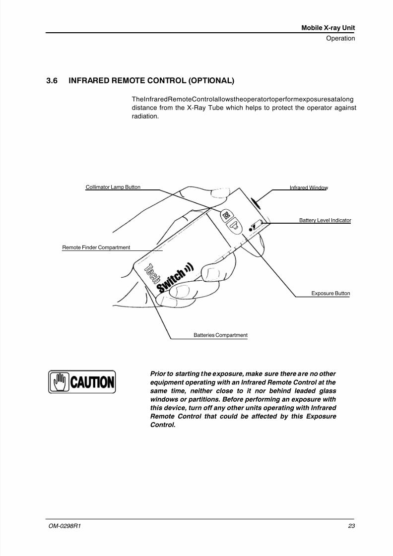
3.6 INFRARED REMOTE CONTROL (OPTIONAL)
TheInfraredRemoteControlallowstheoperatortoperformexposuresatalongdistance from the X-Ray Tube which helps to protect the operator againstradiation.
Collimator Lamp Button Infrared Window
Exposure Button
Battery Level Indicator
Batteries Compartment
Remote Finder Compartment
Prior to starting the exposure, make sure there are no other
equipment operating with an Infrared Remote Control at the
same time, neither close to it nor behind leaded glasswindows or partitions. Before performing an exposure with
this device, turn off any other units operating with Infrared
Remote Control that could be affected by this Exposure
Control.

7/21/2019 Om0298r1i-Mobixray TX-mlp - Rdlg (100505)
http://slidepdf.com/reader/full/om0298r1i-mobixray-tx-mlp-rdlg-100505 32/68
Mobile X-ray Unit
Operation
OM-0298R1 24
3.6.1 OPERATION
Take the Remote Exposure Control device out of its cradle. Aim the RemoteControlatthesensorontheMobileUnitfromamaximumdistanceof10meters.
COLLIMATOR LAMP: Press this button to turn on the Collimator Lamp. Thiscontrol is disabled with Manual Collimators.
EXPOSURE CONTROL : Press this button once to prepare the X-ray Tube forexposure (”Prep” position). When the green light is on, press this button asecondtimeandholditdownuntiltheX-rayUnitcompletestheexposure(”Exp”
position).When the exposure is completed the green light indicator turns off. Return theControl Remote device back to its cradle on the Mobile Unit.
A built-in remote beeping feature will alert the operator when the
Remote Control device is left uncradled.
The preparation cycle is automatically interrupted and returns to stand-by notonly when an exposure is not initiated within 15 seconds after the “Prep” action
but also when the Collimator Lamp is turned on.
If the “Exposure” button is released while making an exposure, the exposure isautomatically aborted.
3.6.2 THE “REMOTE FINDER” DEVICE
The Remote Exposure Control has a built-in remote finder which is very usefulfor locating the remote control device should it become misplaced.
If the Remote Exposure Control is not returned back to its cradle within threeminutes after use, the device will repeat a series of beeps. This series of beepswill continue indefinitely until the device is located and put back into its cradle.
Note .

7/21/2019 Om0298r1i-Mobixray TX-mlp - Rdlg (100505)
http://slidepdf.com/reader/full/om0298r1i-mobixray-tx-mlp-rdlg-100505 33/68
Mobile X-ray Unit
Operation
OM-0298R1 25
3.7 MOTION CONTROLS
UNIT TRAVEL MUST BE PERFORMED IN PARKINGPOSITION. FOR SAFETY REASONS, OPERATIONAL ANDTRAVELSURFACESSHOULDNOTEXCEED5 O INCLINATIONRAMPS.
MONITOR THESYSTEMMOVEMENTS WITH SPECIAL CARE.AVOID ANY IMPACT OF THEUNIT WITH WALLS, FURNITUREOR OTHER ELEMENTS IN THE ROOM THAT MAY CAUSEDAMAGE TO THE EQUIPMENT.
DO NOT DRIVE THE MOBILE UNIT OVER WET SURFACESAND / OR IMPREGNATED WITH CLEANING PRODUCTS(SPECIALLY BLEACH, AMMONIA, ETC.), THE UNIT COULDSLIP AND MOMENTARILY LOSE CONTROL. IT ALSO MAY BLEACHTHEWHEELSCAUSINGDAMAGESTOTHEFLOOR.
MONITOR WITH SPECIAL CARE THE PATIENT POSITION ORANYONE PRESENT, TO AVOID INJURY CAUSED BY UNITMOVEMENTS.
INTRAVENOUS TUBING, CATHETERS AND OTHER PATIENTCONNECTED LINES SHOULD BE ROUTED AWAY FROMMOVING EQUIPMENT.
3.7.1 CONTROL FOR ARM POSITIONING
Both Handgrips of the Tube-Collimator Assembly are used to position theTube-Collimator Assembly in relation to the position of the patient.
ALWAYS USE THESE HAND-GRIPS TO DRIVE THE ARMMOVEMENTS, NEVER PUSH DIRECTLY ON X-RAY TUBE ORCOLLIMATOR.
7/21/2019 Om0298r1i-Mobixray TX-mlp - Rdlg (100505)
http://slidepdf.com/reader/full/om0298r1i-mobixray-tx-mlp-rdlg-100505 34/68
Mobile X-ray Unit
Operation
OM-0298R1 26
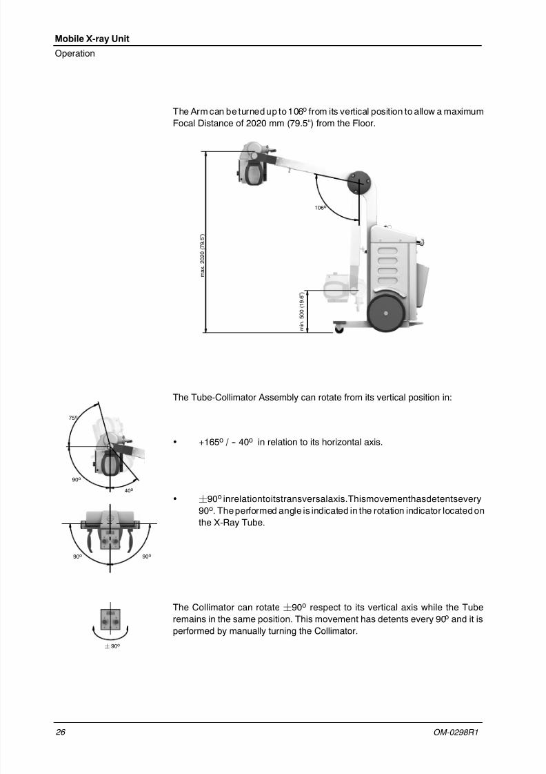
The Arm can be turned up to 106o from its vertical position to allow a maximumFocal Distance of 2020 mm (79.5“) from the Floor.
m a
x .
2 0 2 0 ( 7 9 . 5
” )
106o
m i n .
5 0 0 ( 1 9 . 6
” )
The Tube-Collimator Assembly can rotate from its vertical position in:
• +165o / -- 40o in relation to its horizontal axis.
• ¦90o inrelationtoitstransversalaxis.Thismovementhasdetentsevery90o. The performed angle is indicated in the rotation indicator located onthe X-Ray Tube.
The Collimator can rotate ¦90o respect to its vertical axis while the Tuberemains in the same position. This movement has detents every 90o and it isperformed by manually turning the Collimator.
90o
75o
40o
90o 90o
¦ 90o

7/21/2019 Om0298r1i-Mobixray TX-mlp - Rdlg (100505)
http://slidepdf.com/reader/full/om0298r1i-mobixray-tx-mlp-rdlg-100505 35/68
Mobile X-ray Unit
Operation
OM-0298R1 27
3.7.2 PARKING POSITION
The parking position of the unit provides a safe and easy motion and transport.Bend the Arm and block it with the Arm Safety Hook.
Parking Position
Arm Safety Hook
ALWAYS KEEP THE ARM IN PARKING POSITION EXCEPTWHEN PERFORMING RADIOGRAPHIC EXAMS. THIS WILLPREVENT INJURIES OR UNIT DAMAGE DURINGDISPLACEMENT.

7/21/2019 Om0298r1i-Mobixray TX-mlp - Rdlg (100505)
http://slidepdf.com/reader/full/om0298r1i-mobixray-tx-mlp-rdlg-100505 36/68
Mobile X-ray Unit
Operation
OM-0298R1 28
3.7.3 DISPLACEMENT CONTROLS
The only displacement controls of the Unit are the Front Handle Bar, the BrakeControl Bar and the Blocking Button.
Thebrakes are released by grippingand holding the Brake ControlBar towardstheFrontHandleBar.TheUnitismanuallymovedpushingorpullingitfrombothBars. The front steering wheels and the back main wheels provide comfortabledriving as well as easy positioning of the Unit.
Also, the Unit is provided with a Blocking Button that keeps brakes released forlonger distances. Grip Front Handles and press Blocking Button to releasebrakes and start motion. Press on both Bars to release the Blocking Button andthen release both Bars to stop motion.
TAKE SPECIAL CARE WHEN GRIPPING BOTH BARS TOPREVENT INJURIES CAUSED BY FINGER PINCH .
Blocking ButtonFront Handle Bar
Brake Control Bar
The Unit can be transported over floor differences of up to 50 mm (curbs, steps,elevator gaps, etc). Step down on the base of the Unit to raise the directionalwheels, as shown in the picture below.

7/21/2019 Om0298r1i-Mobixray TX-mlp - Rdlg (100505)
http://slidepdf.com/reader/full/om0298r1i-mobixray-tx-mlp-rdlg-100505 37/68
Mobile X-ray Unit
Operation
OM-0298R1 29
3.8 COLLIMATOR CONTROLS
Collimator controls consist of a push-button to switch ON the Collimator Lampand two knobs to open or close the internal blades. (Also refer to the Collimator
Manual).
After pressing the push-button, the Collimator Lamp remains illuminated for afew seconds before automatically switching OFF.
PROLONGED LIGHTING WITHOUT ALLOWING SUFFICIENTTIME FOR THE LAMP TO COOL CAUSES THE COLLIMATORTO OVERHEAT IN THE INTERNAL AREA NEAR THE LAMP.
The exposure field is adjusted by setting the two knobs (shown below). Thetable on the Collimator Panel shows the number to set with the knobs to openthe blades according to the SID and cassette size to be used.
Collimator Lamp Push-button
Knobs to open or close the Collimator blades
3.9 DOSIMETRY (OPTIONAL)
The Radiation Meter VacuDAP 2000 (optional) consists of an IonizationChamber installed under the Collimator. This shows the radiation measure asthe Dose Area Product (DAP = Dose Area Product) in mGy*cm2.
Press the “Reset ” button to set the radiation value to zero for every new patient.(Refer to the Radiation Meter Manual for further information).
The radiation measure must be performed without any accessory
installed between the Collimator and the patient (filters or
diaphragms).
Radiation Meter (optional)
Note .

7/21/2019 Om0298r1i-Mobixray TX-mlp - Rdlg (100505)
http://slidepdf.com/reader/full/om0298r1i-mobixray-tx-mlp-rdlg-100505 38/68
Mobile X-ray Unit
Operation
OM-0298R1 30
This page intentionally left blank.

7/21/2019 Om0298r1i-Mobixray TX-mlp - Rdlg (100505)
http://slidepdf.com/reader/full/om0298r1i-mobixray-tx-mlp-rdlg-100505 39/68
Mobile X-ray Unit
Operation
OM-0298R1 31
SECTION 4 CONTROL CONSOLE
All controls, indicators and displays located on the Control Console arepositioned depending upon their functions.
The Radiographic module consists of: Power On / Off, Bucky / No BuckySelection, Focal Spot Indicators, RAD Displays, Controls to Increase orDecrease the Radiographic Parameters, Self-diagnostics and X-ray ExposureStatus Indicators.
Use the operating controls as described in this manual. Any other
non-indicated combination may cause an incorrect operation of
the equipment.
8. Film / Screen Combination9. AEC Reset10. Patient Size Selection (APR)11. APR Display Selectors12. Self-Diagnosis Indicator13. Exposure Indicators
1. Power On2. Power Off3. Bucky Selection4. Focal Spots Indicators5. Radiographic Values6. AEC Density Values
7. AEC Field Selection
1 2
3
5
11
12
9
7
8
4
10
12
6
11
13
Note .

7/21/2019 Om0298r1i-Mobixray TX-mlp - Rdlg (100505)
http://slidepdf.com/reader/full/om0298r1i-mobixray-tx-mlp-rdlg-100505 40/68
Mobile X-ray Unit
Operation
OM-0298R1 32
4.1 POWER ON / OFF
ON: Console and the Generator are turned ON by pressing this push-button.This starts a power-up routine, displaying the software version on the Console.
After the power-up routine, the last Workstation used (Bucky or No-Bucky) willbe automatically selected.
OFF: The Console / Generator is turned OFF by pressing this push-button.
4.2 EXPOSURE INDICATORS
READY : Indicates that the technique selected is properly set, there are nointerlock failures or system faults, the anode is rotating and the X-ray Tube isready for exposure.
X-RAY ON: Indicates that the X-ray exposure is in progress. An audible signalwill be heard during the exposure.
4.3 WORKSTATIONS SELECTION
BUCKY SELECTOR: Selects the Bucky (push-button lighted) or No-Bucky.

7/21/2019 Om0298r1i-Mobixray TX-mlp - Rdlg (100505)
http://slidepdf.com/reader/full/om0298r1i-mobixray-tx-mlp-rdlg-100505 41/68
Mobile X-ray Unit
Operation
OM-0298R1 33
4.4 FOCAL SPOT INDICATORS
SMALL FOCAL SPOT: Indicates that the “Small Focal Spot ” of the X-ray Tubehas been selected.
LARGE FOCAL SPOT: Indicates that the “Large Focal Spot ” of the X-ray Tubehas been selected.
The Focal Spot is automatically selected according to the mA
station. The mA station set for the Focal Spot change is
configured by the field engineer during the installation.
The Focal Spot may also be selected (keeping kVp and mAs constant) bypressing:
• “ON” + “ mA or mAs Increase” push-buttons to select Large Focal Spot.
• “ON” + “ mA or mAs Decrease” push-buttons to select Small Focal Spot.
Constant mAs set the maximum mA available and the minimum exposure time.
The Focal Spot change can be done whenever the present
conditions of the X-ray Tube allow it.
Note .
Note .

7/21/2019 Om0298r1i-Mobixray TX-mlp - Rdlg (100505)
http://slidepdf.com/reader/full/om0298r1i-mobixray-tx-mlp-rdlg-100505 42/68
Mobile X-ray Unit
Operation
OM-0298R1 34
4.5 RADIOGRAPHIC PARAMETERS
Refer to section 6.3 for Radiographic Operation Modes
kVp DISPLAY can show:
• The radiographic kVp value selected for the technique.
• The actual X-ray Tube heat unit value after pressing the “On”push-button ( refer to Section 4.8).
• The error messages during a system fault, preceded by the letter “E ”(e.g. E02) ( refer to Section 4.11).
mAs DISPLAY can show:
• The radiographic mAs value selected for the technique.
• When an exposure is made with AEC, it shows the actual mAs at the endof theexposure whenever the “Prep” push-buttonhas not been released.
• If an exposure is aborted by releasing the “Exp” push-button during theexposure, it shows the actual mAs value until the “AEC Reset”
push-button is pressed to reset the error condition.
mA DISPLAY : Shows the radiographic mA value selected for the technique.
Time DISPLAY can show:
• The Time value (in seconds) selected for the technique.
• When an exposure is made with AEC, it shows the back-up Time duringthe exposure and the actual Time at the end of the exposure wheneverthe “Prep” push-button has not been released.
• If an exposure is aborted by releasing the “Exp” push-button during theexposure, it shows the actual Time until the “AEC Reset” push-button ispressed to reset the error condition.
RAD Displays can also show:
• The actual Time, the calculated mAs, and the selected kVp and mAradiographic parameters of the last exposure, with or without AEC, afterpressing the “ AEC Reset ” push-button (values flashing).
• The exposure counters ( refer to Section 4.9).
Note .
kVp
mAs
mA
s

7/21/2019 Om0298r1i-Mobixray TX-mlp - Rdlg (100505)
http://slidepdf.com/reader/full/om0298r1i-mobixray-tx-mlp-rdlg-100505 43/68
Mobile X-ray Unit
Operation
OM-0298R1 35
INCREASE / DECREASE: Radiographic technique values are increased ordecreased by pressing the respective push-buttons. The values increase or
decrease step-by-step each time the corresponding push-button is pressed,and changes faster when either of them is pressed continuously.
• kVp: Selects the X-ray Tube voltage.
• mAs: Selects the exposure in mAs.
• mA: Selects the X-ray Tube current.
• s: Selects the exposure time in seconds.
(Refer to Section 7 for Factor ranges)
If after pressing any of these push-buttons, the technique value is
blocked and an acoustic signal is emitted it could mean that:
Radiographic Parameters Blockage. Whenever the maximum
or minimum limit for any radiographic parameter is reached, the
related Display blinks.
Generator Power Limit. If the power limit (kV x mA) is reached
by increasing the mA up to a maximum possible value, the mA
value is blocked. Flashing values on kV and mA Displays will alert
operator about the situation.
If required, kV could be increased up to its maximum value while
mA value may automatically decrease, as long as mAs value is
kept the same.
Space Charge. If a variation of the kV or mA induces to surpass
the space charge limit in the selected tube, the parameter is
blocked, and a flashing value on the kV Display will alert the
operator about the situation.
Maximum Energy (60 kJ). Only in AEC mode, if a variation of the parameters means that the maximum energy (60 kJ) will be
exceeded, the parameter is blocked. Flashing values on kV and
mAs Displays will alert operator about the situation.
Instantaneous Power. If a technique reaches the instantaneous
power limit of the X-ray Tube (ratings limit or the X-ray Tube is
momentarily overheated), some techniques cannot be selected.
Flashing values on kV and mAs Displays will alert operator about
the situation.
Note .

7/21/2019 Om0298r1i-Mobixray TX-mlp - Rdlg (100505)
http://slidepdf.com/reader/full/om0298r1i-mobixray-tx-mlp-rdlg-100505 44/68
Mobile X-ray Unit
Operation
OM-0298R1 36
4.6 AUTOMATIC EXPOSURE CONTROL (AEC) (OPTIONAL)
Automatic Exposure Control (AEC) produces consistent film density withexcellent contrast regardless of the selected radiographic technique. The AECmodule comprises the controls to activate the Exposure Detector (IonChamber), the Film/Screen Combination, Film Density Compensation and
AEC Reset.
The AEC mode is selected by pressing any of the three AEC Fieldpush-buttons. To exit the AEC mode, press all the illuminated AEC Fieldpush-buttons until none are lit.
In AEC mode the back-up time (or back-up mAs) MUST BE SET MANUALLYby the operator using the Console controls.
The value of the back-up time (or mAs) must be set greater than
the previously considered value for the exposure time (or mAs).
A value above 50% of the considered value is the recommended.
Very extreme values of back-up time (or mAs) should be avoided
to prevent patient from excessive exposure when a control error
is produced.
EXPOSURE DETECTOR: Press central push-button to activate or deactivatethe Mobile-AID Ion Chamber. Buttons at right and left are not used to select theMobile-AID Ion Chamber.
FILM / SCREEN COMBINATION: Each of these push-buttons allowsadjustment of the mAs in relation to a programmed Film / Screen combinationthat may be in use: slow, medium, or fast respectively (200, 400, 800). Eachtime a Film / Screen push-button is selected (illuminated), the others areautomatically deselected.
DENSITY: These push-buttonsareusedto adjust the radiographic film density.
Film density canbe proportionally increased or decreased inseveral steps.Theselected value is shown in the Density Display. The variation percentagedensity between steps can be changed during the equipment calibration by theengineer according to customer preferences (the percentage by default is25%).
Note .

7/21/2019 Om0298r1i-Mobixray TX-mlp - Rdlg (100505)
http://slidepdf.com/reader/full/om0298r1i-mobixray-tx-mlp-rdlg-100505 45/68
Mobile X-ray Unit
Operation
OM-0298R1 37
AECRESET: If theexposure is abortedbytheAEC back-uptimer, theindicatoronthe“ AEC Reset ” push-button blinks accompanied by an audible alarm. The
next exposure is inhibited until the AEC function is reset by pressing the “ AECReset ” push-button. When the Generator is in “Prep” mode, the AEC functioncan not be reset.
The “ AEC Reset ” push-button may blink when the kVp value, the AEC Densityand the Film/Screen Combination select a technique that is out of the operativerange with AEC, inhibiting the next exposure. Change any parameter (kVpvalue, AEC Density and/or Film/Screen Combination) in order to obtain atechnique enabled for AEC.
4.7 ANATOMICAL PROGRAMMER (APR)
The Anatomical Programmer (APR) module is comprised of the controls whichselect the Patient Size and Display Selectors. The process is shown on the
APR Display.
The APR techniques are factory pre-programmed according to differentstandard techniques that combines six Body Regions with their AnatomicalViews (Organ + Projection). Besides the radiographic parameters, selectionsof the workstation or AEC can be assigned to the APR techniques. Theseselections will always be common for all the patient sizes of each Anatomical
View. These techniques may be modified and stored again by the operator inthe “ APR working File” .
The APR techniques are intended as a guide only. Accurate exposure factorsdepend, among other things, onBucky grid factors, table topabsorption, screenfilm combinations and film processing.
APR modeactivates when one of the three Patient Size (small, medium or largesize) is selected (push-button lighted), and deactivates by deselecting any ofthem.
APR language may be changed by pressing the “Power On”
push--button immediately after selecting one of the patient size
(APR activation). Language selected remains stored even after
the equipment is turned Off. Different languages available
according to order specifications.
If an APR technique is to be stored with AEC parameters, a
suitable back-up time (and/or mAs) MUST be stored in the
programme by the operator.
Note .
Note .

7/21/2019 Om0298r1i-Mobixray TX-mlp - Rdlg (100505)
http://slidepdf.com/reader/full/om0298r1i-mobixray-tx-mlp-rdlg-100505 46/68
Mobile X-ray Unit
Operation
OM-0298R1 38
APR DISPLAY : Shows the different Body Regions and Anatomical Viewsavailable for each APR technique, and the final APR selection.
Because each area of the APR Display is limited in length to eight characters,some regions and views are abbreviated.
PATIENT SIZE: These push-buttons are used to adapt the APR techniquechosen according to patient size. Six patient sizes are available. The threeright-hand push-buttons select Small, Medium and Large adult sizes (only oneis illuminated when selected). The left-hand paediatric push-button changesthe function of the right-hand three push-buttons from adult patient size topaediatric patient size. (In this mode, the “Paediatric” push-button and one of
the other three buttons may be illuminated at the same time).
ANATOMICAL VIEW SELECTORS: Each push-button is related with thenearestareaof theAPR Display and they areusedto selectone of thedisplayedBody Regions, Organs and Projections. The selected Region and Viewsappears in negative block ( SKULL ).
The APR display shows the Body Regions, Organs and Projections. When a
Body Region has been selected its indication is locked on the screen and the APR Display shows directly all its respective Organs. In some cases, an Organmay show several Projections.
When theAPR selection is finished, the Consoleshows thefinal selection(APRDisplay), its respective parameters (RAD Display), the Workstation and AECcontrols related to the technique.
To go back to the previous level, press on the right-lower APR push-buttonwhich displays the “ return” symbol.

7/21/2019 Om0298r1i-Mobixray TX-mlp - Rdlg (100505)
http://slidepdf.com/reader/full/om0298r1i-mobixray-tx-mlp-rdlg-100505 47/68
Mobile X-ray Unit
Operation
OM-0298R1 39
APR TECHNIQUE CHANGES
The APR techniques are factory pre-programmed to standard technique sets. All parameters of the APR techniques may be manually overridden as requiredby the operator and stored in the non-volatile memory for later use.
If the operator determines that some factors in an APR technique should bere-programmed, use the following procedure:
1. Select an APR technique and modify the factors and selections ofWorkstations or AEC which require to be re-programmed.
2. Verify that all factors of the technique are at the required values.
3. Store the new technique by first pressing the selected Patient Size andwithout releasing it press the Projection selected. (Refer to
Illustration 4-1).
The newly selected technique is now stored in the memory and can berecalled for future examinations.
This procedure only changes the technique values of the selected
patient size; repeat the procedure for other patient sizes.
Illustration 4-1APR Storage Push-buttons
3
2
4 8
7
6
51
Example : press push-buttons: 1 st Medium Patient Size and Lateral Projection, to store the APR technique selected.
LATERAL
SKULL
SKULL
SEMIAX.
LATERAL
AXIAL
AP/PA SPECIAL
Note .

7/21/2019 Om0298r1i-Mobixray TX-mlp - Rdlg (100505)
http://slidepdf.com/reader/full/om0298r1i-mobixray-tx-mlp-rdlg-100505 48/68
Mobile X-ray Unit
Operation
OM-0298R1 40
Table 4-1APR Projections (English version)
BODY REGION / ORGAN / PROJECTION
SKULL
AP/PA
LATERAL
SEMIAXIAL
AXIAL
SPECIAL
THORAX AP
LATERALODONTOID AP
ORBITA -- UPPER RIBS AP/PA
OBLIQUEC-SPINE
AP
LATERAL
OBLIQUE
SKULL
PETROUSBONES
/ STENVERS--
THORAX LOWER RIBS
AP/PA
OBLIQUE SPINET-SPINE
AP
LATERAL
OBLIQUE
MASTOID -- STERNUMLATERAL
OBLIQUEL-SPINE
AP
LATERAL
OBLIQUE
PARANASALSINUSES
-- SCAPULA
AP/PA
LATERAL
OBLIQUE
L5--S1 AP
LATERAL
SELLA LATERAL CLAVICLE AP/PA SACRUM AP
LATERAL
NOSE LATERAL
ABDOMEN
AP/PA
LATERAL
DECUBITUS
STANDING
FEMUR AP
LATERALSHOULDER
AP
SEMIAXIAL
OBLIQUE
KIDNEY AP KNEE AP
LATERALHUMERUS
AP
LATERAL
KIDNEY / URETER
AP PATELLALATERAL
AXIALELBOW
PA
LATERAL
ABDOMEN / PELVIS
GALL-BLADDER
AP
OBLIQUE
LOWEREXTREMITIES
LOWER LEG AP
LATERAL
UPPEREXTREMITIES
FOREARM PA
LATERAL
PELVIS AP
LATERALANKLE
AP
LATERAL
OBLIQUE
WRIST
AP
LATERAL
OBLIQUE
HIP
AP
MED / LAT
AXIAL
FOOT
AP
LATERAL
OBLIQUE
HAND
AP
LATERAL
OBLIQUE
TOES AP/LAT/OBLIQ FINGER AP
LATERAL

7/21/2019 Om0298r1i-Mobixray TX-mlp - Rdlg (100505)
http://slidepdf.com/reader/full/om0298r1i-mobixray-tx-mlp-rdlg-100505 49/68
Mobile X-ray Unit
Operation
OM-0298R1 41
Table 4-1 (cont.)APR Projections (Spanish version)
ZONA CUERPO / ORGANO / PROYECCION
CRANEO
AP/PA
LATERAL
SEMIAXIAL
AXIAL
ESPECIAL
TORAX AP
LATERALODONTAL AP
ORBITA -- COSTILLASSUPERIORES
AP/PA
OBLICUO
COLUMNACERVICAL
AP
LATERAL
OBLICUO
CRANEOPEÑASCO --
TORAX
COSTILLASINFERIORES
AP/PA
OBLICUO COLUMNA
COLUMNADORSAL
AP
LATERAL
OBLICUO
MASTOID -- ESTERNONLATERAL
OBLICUO
COLUMNALUMBAR
AP
LATERAL
OBLICUO
SEN. PAR. -- ESCAPULA
AP/PA
LATERAL
OBLICUO
L5--S1 AP
LATERAL
SILLA TURCA LATERAL CLAVICULA AP/PA SACRO AP
LATERAL
NARIZ LATERAL
ABDOMEN
AP/PA
LATERAL
DECUBIT0
CARGA
FEMUR AP
LATERALHOMBRO
AP
SEMIAXIAL
OBLICUO
RIÑON AP RODILLA AP
LATERALHUMERO
AP
LATERAL
RIÑON / URETRA
AP ROTULALATERAL
AXIALCODO
PA
LATERAL
ABDOMEN / PELVIS
VESICULABILIAR
AP
OBLICUO
EXTREMIDADESINFERIORES
PIERNAINFERIOR
AP
LATERAL
EXTREMIDADESSUPERIORES
ANTEBRAZO PA
LATERAL
PELVIS AP
LATERALTOBILLO
AP
LATERAL
OBLICUO
MUÑECA
AP
LATERAL
OBLICUO
CADERA
AP
MED / LAT
AXIAL
PIE
AP
LATERAL
OBLICUO
MANO
AP
LATERAL
OBLICUO
DEDOSDEL PIE
AP/LAT/OBL DEDOS DELA MANO
AP
LATERAL

7/21/2019 Om0298r1i-Mobixray TX-mlp - Rdlg (100505)
http://slidepdf.com/reader/full/om0298r1i-mobixray-tx-mlp-rdlg-100505 50/68
Mobile X-ray Unit
Operation
OM-0298R1 42
Table 4-1 (cont.)APR Projections (French version)
REGION DU CORPS / ORGANE / PROJECTION
CRANE
AP/PA
LATERAL
SEMIAXIAL
AXIAL
SPECIAL
THORAX AP
LATERALATLAS AP
ORBITAE -- COTES SUP. AP/PA
OBLIQUECOL. CERV
AP
LATERAL
OBLIQUE
CRANEM. PEDRO --
THORAX COTES INF.
AP/PA
OBLIQUE COLONNECOL. DORS
AP
LATERAL
OBLIQUE
MASTOID -- STERNUMLATERAL
OBLIQUECOL. LOMB
AP
LATERAL
OBLIQUE
SINUS -- OMOPLATE
AP/PA
LATERAL
OBLIQUE
L5--S1 AP
LATERAL
SELLA LATERAL CLAVICLE AP/PA SACRUM AP
LATERAL
NEZ LATERAL
ABDOMEN
AP/PA
LATERAL
DECUBITUS
DEBOUT
FEMUR AP
LATERALEPAULE
AP
SEMIAXIAL
OBLIQUE
REINS AP GENOU AP
LATERALHUMERUS
AP
LATERAL
URETERE AP ROTULELATERAL
AXIALCOUDE
PA
LATERAL
ABDOMEN / BASSIN
VES. BIL. AP
OBLIQUE
EXTREMITESINFERIEUR
JAMBE INF. AP
LATERAL
EXTREMITESSUPERIEUR
BRAS. INF. PA
LATERAL
PELVIS AP
LATERALCHEVILLE
AP
LATERAL
OBLIQUE
POIGNET
AP
LATERAL
OBLIQUE
HANCHE
AP
MED / LAT
AXIAL
PIED
AP
LATERAL
OBLIQUE
MAIN
AP
LATERAL
OBLIQUE
ORTEIL AP/LAT/OBLIQ DOIGTS AP
LATERAL

7/21/2019 Om0298r1i-Mobixray TX-mlp - Rdlg (100505)
http://slidepdf.com/reader/full/om0298r1i-mobixray-tx-mlp-rdlg-100505 51/68
Mobile X-ray Unit
Operation
OM-0298R1 43
Table 4-1 (cont.)APR Projections (German version)
REGION / ORGAN / PROJEKTION
SCHÄEDEL
AP/PA
LATERAL
HALBAX.
AXIAL
SPEZIAL
THORAX AP
LATERALDENS AP
ORBITA -- OBERERRIPPEN
AP/PA
OBLIQUEHWS
AP
LATERAL
OBLIQUE
SCHÄEDELSTENVERS --
THORAX
UNTERERRIPPEN
AP/PA
OBLIQUE W. SAEULEBWS
AP
LATERAL
OBLIQUE
MASTOID -- STERNUMLATERAL
OBLIQUELWS
AP
LATERAL
OBLIQUE
NNH -- SCAPULA
AP/PA
LATERAL
OBLIQUE
L5--S1 AP
LATERAL
SELLA LATERAL CLAVICUL AP/PA SAKRUM AP
LATERAL
NASE LATERAL
ABDOMEN
AP/PA
LATERAL
DECUBIT.
STEHEND
O. SCHENKEL AP
LATERALSCHULTER
AP
HALBAX.
OBLIQUE
NIERE AP KNIE AP
LATERALOBERARM
AP
LATERAL
NIERE / UR AP PATELLALATERAL
AXIALELLENBOGEN
PA
LATERAL
ABDOMEN / BECKEN
GALLEN-BLASE
AP
OBLIQUE
UNTEREREXTREM.
U. SCHENKEL AP
LATERAL
OBEREREXTREM.
UNTERARM PA
LATERAL
BECKEN AP
LATERALSPRGEL.
AP
LATERAL
OBLIQUE
HANDGELENK
AP
LATERAL
OBLIQUE
HUEFTE
AP
MED / LAT
AXIAL
FUSS
AP
LATERAL
OBLIQUE
HAND
AP
LATERAL
OBLIQUE
ZEHEN AP/LAT/OBLIQ FINGER AP
LATERAL

7/21/2019 Om0298r1i-Mobixray TX-mlp - Rdlg (100505)
http://slidepdf.com/reader/full/om0298r1i-mobixray-tx-mlp-rdlg-100505 52/68
Mobile X-ray Unit
Operation
OM-0298R1 44
Table 4-1 (cont.)APR Projections (Polish version)
REGION APR / ORGAN / PROJEKCJA
CZASZKA
AP/PA
BOCZNE
POLOSIOWE
OSIOWE
SPECIAL
KLATKA P AP
BOCZNEOBROTNIK AP
OCZODOLY -- ZEBRA G. AP/PA
SKOSKR. SZYJ.
AP
BOCZNE
SKOS
CZASZKAUSZY SR. --
KLATKA PZEBRA D.
AP/PA
SKOS KREGOSL.KR. PIER.
AP
BOCZNE
SKOS
PODSTAWA -- MOSTEK BOCZNE
SKOSKR. LEDZ.
AP
BOCZNE
SKOS
ZATOKI -- LOPATKA
AP/PA
BOCZNE
SKOS
C. L5--S1 AP
BOCZNE
SIODELKO BOCZNE OBOJCZYK AP/PA K. KRZYZ. AP
BOCZNE
NOS BOCZNE
J. BRZUSZ
AP/PA
BOCZNE
BOK-LEZ
BOK-STOJ
UDO AP
BOCZNEBARK
AP
POLOSIOWE
SKOS
NERKI AP KOLANO AP
BOCZNERAMIE
AP
BOCZNE
P. MOCZ. AP RZEPKABOCZNE
OSIOWELOKIEC
PA
BOCZNE
J. BRZUSZ P. ZOLCI. AP
SKOSKONCZ D. GOLEN AP
BOCZNEKONCZ G. PRZEDR. PA
BOCZNE
MIEDNICA AP
BOCZNESTAW ZK.
AP
BOCZNE
SKOS
NADGARS.
AP
BOCZNE
SKOS
BIODRA
AP
BOCKNE
OSIOWE
STOPA
AP
BOCZNE
SKOS
DLON
AP
BOCZNE
SKOS
PALCE AP/BOK PALCE AP
BOCZNE

7/21/2019 Om0298r1i-Mobixray TX-mlp - Rdlg (100505)
http://slidepdf.com/reader/full/om0298r1i-mobixray-tx-mlp-rdlg-100505 53/68
Mobile X-ray Unit
Operation
OM-0298R1 45
Table 4-1 (cont.)APR Projections (Turkish version)
VÜCUT KISMI / ORGAN / PROJEKSIYON
KAFA
AP/PA
LATERAL
SEMIAKSIYAL
AKSIYAL
ÖZEL
TORAKS AP
LATERALODONTOID AP
GÖZ ÇUK -- Ü. KABUR. AP/PA
OBLIK C. OMUR
AP
LATERAL
OBLIK
KAFASTENVERS --
TORAKSA. KABUR.
AP/PA
OBLIK OMURGAT. OMUR
AP
LATERAL
OBLIK
MOSTOID -- STERNUMLATERAL
OBLIK L. OMUR
AP
LATERAL
OBLIK
SIN.PAR. -- SKAPULA
AP/PA
LATERAL
OBLIK
L5--S1 AP
LATERAL
SELLA LATERAL KLAVICU. AP/PA SAKRUM AP
LATERAL
BURUN LATERAL
BATIN
AP/PA
LATERAL
DEKUBIT
AYAKTA
FEMUR AP
LATERALOMUZ
AP
SEMIAKS
OBLIK
BÖBREK AP DIZ AP
LATERALKOL
AP
LATERAL
ÜRINER AP PATELLALATERAL
AKSIYALDIRSEK
PA
LATERAL
BATIN/PELVIS SAFRA K. AP
OBLIK
A.EXTREM
CRURAL AP
LATERAL
Ü.EXTREM
ÖN KOL PA
LATERAL
PELVIS AP
LATERALA. BILEGI
AP
LATERAL
OBLIK
BILEK
AP
LATERAL
OBLIK
KALÇA
AP
MED / LAT
AKSIYAL
AYAK
AP
LATERAL
OBLIK
EL
AP
LATERAL
OBLIK
A. PARMAK AP/LAT/OBLIK PARMAK AP
LATERAL

7/21/2019 Om0298r1i-Mobixray TX-mlp - Rdlg (100505)
http://slidepdf.com/reader/full/om0298r1i-mobixray-tx-mlp-rdlg-100505 54/68
Mobile X-ray Unit
Operation
OM-0298R1 46
4.8 HEAT UNITS
This X-ray Generator is equipped with a Heat Unit Calculator. Duringexposures, the Heat Units are calculated and totalled.
To view theremainingHeat Units,press and hold the“On” push-button.ThekVpDisplay shows the percentage of Heat Units that remain preceded by the letter“H”. For example, a display of “H75” would indicate that 75% of Heat Unitscapacity of the X-ray Tube remains. “H -- -- ” indicates that all the capacityremains. The kVp Display reverts to its normal function after releasing the “On”push-button.
4.9 EXPOSURE COUNTERS
The operator can read the number of exposures made by the Generator, asindicated below:
Press and hold and press once
The number of exposures are shown on the kVp and mAs Displays, up to amaximum of 999,999 exposures.
kVp mAs
= 123,456 exposures
4.10 SELF-DIAGNOSIS INDICATORS
ERROR INDICATOR: Lights when a malfunction is detected in the system,alerting the operator that one of the following error inhibits X-ray exposures.Duringnormaloperation of the system, theseerror indicators are directlyshownon the APR Display or as an error code on the kVp Display. (Refer to Section
4.11).• Tube Overload (T.OVL): Indicates that either technique selected is
beyond the X-ray Tube ratings or the present conditions of the X-rayTube inhibit the exposure (anode overheated). Parameters for nextexposure may be temporally limited by the Generator (change theexposure values or wait for the X-ray Tube to cool).
Check that heat units available are lower than the ones calculated for thenext exposure (heat units close to zero). Reduce exposure factors orwait for the X-ray Tube to cool. (To display Heat Units refer to Section
4.8).

7/21/2019 Om0298r1i-Mobixray TX-mlp - Rdlg (100505)
http://slidepdf.com/reader/full/om0298r1i-mobixray-tx-mlp-rdlg-100505 55/68
Mobile X-ray Unit
Operation
OM-0298R1 47
• Generator Overload (G.OVL): Indicates that the exposure wasinterrupted because arcing or malfunctioning occurred during exposure
on the HV circuitry (X-ray Tube, HV Transformer and/or HV Cables) ora failure of IGBT module (overheated or defective IGBTs) was detected.
It can also appear when making a lengthy or high powered exposure withthe X-ray Tube cool (X-ray Tube has not been sufficiently warmed-up).
• Rotor Error (ROTOR) : Indicates that the X-ray Tube anode is notrotating while “Prep” is active, then exposures are inhibited.
• Heat Unit (HEAT): Indicates that the X-ray Tube thermostat /
pressurestat is open due to overheating of the Tube housing (housing istoo hot; wait for the housing to cool) or to a thermostat / pressurestatmalfunction (housing is cool). Heat units may rise to any value.
• Technique Error (TECH): If activated during exposure it means that:
EXPOSURE HAS BEEN INTERRUPTED BY THE “SECURITY TIMER” BECAUSE OF A FAILURE IN THE SYSTEM. TURNTHE GENERATOR OFF AND CALL FIELD SERVICE.
This error can be also shown after an APR technique selection to advisethat exposure parameters displayed on the Console are not the valuesstored for this APR technique. Exposure parameters are adapted by theGenerator to enable other permitted values.
4.11 ERROR CODES
Error codes indicate the potential cause of a system failure. They areintermittently shown on the kVp Display at the same time an alarm sounds. Ingeneral, to remove the error indication on the Console keep pressed the “ AEC
Reset ” push-button till the alarm goes off. (Refer to Table 4-2).
All these error codes are preceded by the letter “E ” (i.e., E01) and they willenable the operator to indirectly convey the possible source of error to servicepersonnel. This may prevent the need for a service call or enable servicepersonnel to anticipate corrective actions prior to arriving on site.

7/21/2019 Om0298r1i-Mobixray TX-mlp - Rdlg (100505)
http://slidepdf.com/reader/full/om0298r1i-mobixray-tx-mlp-rdlg-100505 56/68
Mobile X-ray Unit
Operation
OM-0298R1 48
Table 4-2Error Codes
ERROR DESCRIPTION WHAT TO DO
-- -- -- -- -- --on Display
System failure. This indication may appear together with anerror on the Console, and indicates that the error is notcorrectable unless the equipment is turned OFF.
Turn the Generator OFF and ON.If the equipment remains inoperative, turn it OFF and call Field Service.
E01, E02 Communication error.Turn the Generator OFF, check the proper external cable connectionsand then turn the Generator ON. If the equipment remains inoperative,turn it OFF and call Field Service.
E03 System failure.
E04The Power Cabinet has activated “Preparation” without aConsole command intervention.
Turn the Generator OFF and ON.If the equipment remains inoperative, turn it OFF and call Field Service.
E05 External exposure activated during power-up.
Release any external exposure device or push-buttons.
Turn the Generator OFF and ON.If the equipment remains inoperative, turn it OFF and call Field Service.
E06“Exposure” or/and “Preparation” orders are activated duringpower-up.
Release all the controls.Turn the Generator OFF and ON.If the equipment remains inoperative, turn it OFF and call Field Service.
E07, E08 X-ray Tube configuration error.Press the “ AEC Reset ” push-button.If the error code persists, turn the Generator OFF and ON.If the equipment remains inoperative, turn it OFF and call Field Service.
E09
Generator Overload error. The exposure has beeninterrupted because an arcing or malfunction on the HVcircuitry (X-ray Tube, HV Transformer and/or HV Cables)has occurred during the exposure; or a failure of IGBTmodule (overheated or defective IGBTs) has been detected.
A lengthy and high powered exposure with the X-ray tubecool (X-ray Tube has not been warmed-up) will also showthis error.
This error does not require to press the “ AEC Reset ” push-button, itsindication disappears automatically.If the error code persists, turn the Generator OFF and wait 30 minutesbefore turning it ON again.
If the equipment remains inoperative, turn it OFF and call Field Service.
E10, E11 System failure.Press the “ AEC Reset ” push-button.If the error code persists, turn the Generator OFF and ON.If the equipment remains inoperative, turn it OFF and call Field Service.
E12 No mA during exposure or mA value is out of range.
E13
No kV during exposure or kV value is out of range.
This error may be due to the value introduced in memoryE69 (line current) and the configuration of the line current jumper on the Capacitors Charging Board not coinciding.
Press the “ AEC Reset ” push-button.Repeat with same technique values, If the error code persists try withanother combinations of kV and mA values.If the equipment remains inoperative, turn it OFF and call Field Service.
E14, E15 System failure.
Press the “ AEC Reset ” push-button.
If the error code persists, turn the Generator OFF and ON again.If the equipment remains inoperative, turn it OFF and call Field Service.
E16 Invalid value of: kV, mA or kW.Decrease kV, mA or both. Press the “ AEC Reset ” push-button.If the error code persists, turn the Generator OFF and ON.If the equipment remains inoperative, turn it OFF and call Field Service.
E17 Communication error or system failure.Turn the Generator OFF and ON.If the equipment remains inoperative, turn it OFF and call Field Service.
E18Rotor error. The X-ray tube anode is not rotating while“Prep” is active, then exposures are inhibited, or the X-raytube anode is r otating without console command.
This error does not require to press the “ AEC Reset ” push-button, itsindication disappears automatically.If the error code persists, turn the Generator OFF and ON.If the equipment remains inoperative, turn it OFF and call Field Service.
E19, E20 System failure.Turn the Generator OFF and ON.If the equipment remains inoperative, turn it OFF and call Field Service.

7/21/2019 Om0298r1i-Mobixray TX-mlp - Rdlg (100505)
http://slidepdf.com/reader/full/om0298r1i-mobixray-tx-mlp-rdlg-100505 57/68
Mobile X-ray Unit
Operation
OM-0298R1 49
Table 4-2 (cont.)Error Codes
ERROR DESCRIPTION WHAT TO DO
E21, E22 Incorrect selection of the X-ray Tube.
E23 System failure. Press the “ AEC Reset ” push-button.
E24 Bucky not ready for an exposure.If the error code persists, turn the Generator OFF and ON.If the equipment remains inoperative, turn it OFF and call Field Service.
E26, E27 System failure.
, .
E33 Serial Communication error.
Press the “ AEC Reset ” push-button.Check that communication cable between Generator and console isproperly c onnected.If the error code persists, turn the Generator OFF and ON.If the equipment remains inoperative, turn it OFF and call Field Service.
E34
Technique error. If it activates during the exposure it meansthat the exposure has been interrupted by the “SecurityTimer” because of a system failure. Call Field Service.This error can also be shown after an APR techniqueselection to advise that exposure parameters displayed onthe console are not the values stored for this APRtechnique. Exposure parameters are adapted by theGenerator to enable other values.
E36
Heat Units error. The X-ray Tube thermostat / pressurestatis open due to an overheated tube housing (housing is toohot, wait for the housing to cool) or a thermostat / pressurestat malfunction (housing is cool). Heat units mayrise to any value.
These errors do not require the “ AEC Reset ” push-button to be pressed,their indications disappear automatically.If the error code persists, turn the Generator OFF and ON.If the equipment remains inoperative, turn it OFF and call Field Service.
E37
Tube Overload error. The technique selected is beyond theX-ray tube ratings or present conditions of the X-ray tubeinhibit the exposure (anode overheated). Parameters fornext exposure may be temporally limited by the Generator(change the exposure values or wait for the X-ray tube tocool). Check that heat units available are lower than thecalculated for the next exposure (heat units close to zero).Reduce exposure factors or wait for the X-ray tube to cool.
E47Capacitors are not charged when “Prep” control is activated.The exposure is inhibited until the Capacitors are charged.
Press the “ AEC Reset ” push-button.Wait one minute for the Capacitor to charge-up before activating the“Prep” control.If the error code persists, turn the Generator OFF and ON.If the equipment remains inoperative, turn it OFF and call Field Service.
E48Collimator Error. A failure on the Automatic Collimator hasbeen detected (blades are fully open or in movement duringexposure, etc. )
Press the “ AEC Reset ” push-button.If the error code persists, turn the Generator OFF and ON.
E50 Exposure has been aborted by the Operator.If the equipment remains inoperative, turn it OFF and call Field Service.
E95 Exposure aborted by the AEC Rapid Termination.Press the “ AEC Reset ” push-button. Select the correct Ion Chamber ormodify parameters. Repeat the exposure.If the equipment remains inoperative, turn it OFF and call Field Service.
E96 Voltage missing in the Capacitors Charger Board. Press the “ AEC Reset ” push-button.
E97 Unbalanced charge level in Capacitors.If the error code persists, turn the Generator OFF and ON.If the equipment remains inoperative, turn it OFF and call Field Service.
E98 Service Mode Active.Press the “ AEC Reset ” push-button and call Field Service. This errordoes not inhibit normal operation.

7/21/2019 Om0298r1i-Mobixray TX-mlp - Rdlg (100505)
http://slidepdf.com/reader/full/om0298r1i-mobixray-tx-mlp-rdlg-100505 58/68
Mobile X-ray Unit
Operation
OM-0298R1 50
This page intentionally left blank.

7/21/2019 Om0298r1i-Mobixray TX-mlp - Rdlg (100505)
http://slidepdf.com/reader/full/om0298r1i-mobixray-tx-mlp-rdlg-100505 59/68
Mobile X-ray Unit
Operation
OM-0298R1 51
SECTION 5 OPERATING SEQUENCES
5.1 START-UP ROUTINE
After turning ON the Console, the Generator will go through a start-up routineconducting an automatic self-test that will show information usable only byservice personnel.
After the power-up has been completed the Console should display normalradiographic factors. If there is a malfunction, error messages will be displayedon the RAD kVp Display specifying the fault.
Some indicators on the Console are used to provide service
information during the start-up process. These indicators should
be ignored by the operator until the unit has completed its
power-up sequence.
5.2 X-RAY TUBE WARM-UP PROCEDURE
Before effecting X-ray exposures ensure that the Tube is
properly warmed-up. Make sure that no persons will be
inadvertently exposed to unnecessary X-rays during this
procedure.
Routine exposures should not be effected unless the Tube is previouslywarmed-up, this prolongs X-ray Tube life.
ItisrecommendedthatthefollowingprocedurewillbeperformedforX-rayTubewarm-up, at the start of each day and when the Tube selected has not been inuse for approximately one hour.
This warm-up procedure is used for a typical X-ray Tube.
Consult the X -ray Tube manufacturer instructions for the
actual Tube in use, comparing its recommendations with this
procedure. If there is conflict with this procedure, comply
with the Tube manufacturer’s instructions.
Note .

7/21/2019 Om0298r1i-Mobixray TX-mlp - Rdlg (100505)
http://slidepdf.com/reader/full/om0298r1i-mobixray-tx-mlp-rdlg-100505 60/68

7/21/2019 Om0298r1i-Mobixray TX-mlp - Rdlg (100505)
http://slidepdf.com/reader/full/om0298r1i-mobixray-tx-mlp-rdlg-100505 61/68

7/21/2019 Om0298r1i-Mobixray TX-mlp - Rdlg (100505)
http://slidepdf.com/reader/full/om0298r1i-mobixray-tx-mlp-rdlg-100505 62/68
Mobile X-ray Unit
Operation
OM-0298R1 54
5.5 APR OPERATION
An examination using an APR technique could consist of the following:
1. Make sure that the X-ray Tube is properly warmed-up.
2. Position the patient for the examination.
3. Select the “Patient Size” corresponding to the patients anatomy. ThisoperationstartstheAPRmode. Selectthe“Pediatric”buttonifthepatientis not an adult.
4. Select a general “Body Region” and an “ Anatomical View ” of theindicated on the APR Display.
5. Techniqueparameters,Focal Spot, AEC,etc...corresponding tothe APRselection are displayed and indicated on the Control Console. If needed,the parameters and selections can be directly modified by the operator.
6. Continue with the normal procedure for a typical RAD examination.(Refer to Section 5.3 - step 4.)

7/21/2019 Om0298r1i-Mobixray TX-mlp - Rdlg (100505)
http://slidepdf.com/reader/full/om0298r1i-mobixray-tx-mlp-rdlg-100505 63/68

7/21/2019 Om0298r1i-Mobixray TX-mlp - Rdlg (100505)
http://slidepdf.com/reader/full/om0298r1i-mobixray-tx-mlp-rdlg-100505 64/68

7/21/2019 Om0298r1i-Mobixray TX-mlp - Rdlg (100505)
http://slidepdf.com/reader/full/om0298r1i-mobixray-tx-mlp-rdlg-100505 65/68
Mobile X-ray Unit
Operation
OM-0298R1 57
SECTION 7 TECHNICAL SPECIFICATIONS
Maximum Power kW(Refer to Identification Label)
16 kW 20 kW 32 kW
40 to 125(40 to 150 optional)
40 to 125(40 to 150 optional)
40 to 150
kVp Range
From 40 kV to 125 kV or 150 kV in 1 kV steps.(Depending on the Generator model)
0.1 to 250 0.1 to 320 0.1 to 500
mAs Range
Product of mA x Time values from 0.1 mAs to 250, 320 or 500 mAs(Depending on the Generator model)
(Maximum mAs are only available with Power Lines or at least 16A at 230 VAC;
for Lines with lower Voltage and/or current, maximum mAs is reducer)
(The mAs value is limited depending on the selected kVp and mA values.
The higher mAs values are obtained when selecting low kVp and mA values).
10 to 250 10 to 320 10 to 500
mA Range From 10 mA to 250, 320 or 500 mA through the following mA stations:10, 12.5, 16, 20, 25, 32, 40, 50, 64, 80, 100, 125, 160, 200, 250, 320, 400, 500.
(Depending on the Generator model)
Exposure Time Range
From 1 millisecond to 10 seconds through the following Time stations:Milliseconds: 1, 2, 3, 4, 5, 6, 8, 10, 12, 16, 20, 25, 32, 40, 50, 64, 80,
100, 125, 160, 200, 250, 320, 400, 500, 640, 800.Seconds: 1, 1.25, 1.6, 2, 2.5, 3.2, 4, 5, 6.4, 8, 10.
0.1 mAs to 250 mAs 0.1 mAs to 320 mAs 0.1 mAs to 500 mAs
AEC
Exposure Time: Nominal shortest irradiation Time = 1ms
Power Output (@ 0,1s)
125 kVp @125 mA100 kVp @ 160 mA80 kVp @ 200 mA64 kVp @ 250 mA
125 kVp @ 160 mA100 kVp @ 200 mA80 kVp @ 250 mA62 kVp @ 320 mA
150 kVp @ 200 mA128 kVp @ 250 mA100 kVp @ 320 mA80 kVp @ 400 mA64 kVp @ 500 mA
The Duty Cycle is continuous, but limits depend on the capacity of the X-ray TubeDuty Cycle
Maximum leakage radiation depends on the type of X-ray Tube
Collimator Manual with electronic timer and meter
Standard X-ray Tube
Low Speed -- Rotating AnodeFocal Spots: 0.3 mm / 1.0 mm
Anode kHU / kVp: 140 kHU / 150 kVpTarget Angle: 12°
Inherent Filtration of X-ray Source (Tube + Collimator): refer to Identification LabelOther X-ray Tubes available on request

7/21/2019 Om0298r1i-Mobixray TX-mlp - Rdlg (100505)
http://slidepdf.com/reader/full/om0298r1i-mobixray-tx-mlp-rdlg-100505 66/68
Mobile X-ray Unit
Operation
OM-0298R1 58
Maximum Power kW(Refer to Identification Label)
16 kW 20 kW 32 kW
100 / 110 / 120 / 208 / 230 / 240 VAC -- Single-Phase, 50 / 60 Hz
Automatic Line Compensation¦10% VACPower Line Adaptation for local conditions from 8 to 16 A
Connection to standard outlets with GND that accomplishes local regulations
Power Line Operation
The Line Circuit Breaker installed in the Mobile Unit is 10 A (1P+N curve type D),the Power Line Installation should be provided with a Differential of 30 mA Sensitivity
and with a Thermomagnetic Interruptor / Circuit Breaker of:² 13 A (curve type D) or ² 20 A (curve type C) or ² 32 A (curve type B)
Line Impedance should comply with Standard IEC--60601.2.7.Maximum Line Impedance depends on the Line Voltage as follows:
for Vrms of 240 V Max. Line Impedance is 0.38 Ωfor Vrms of 230 V Max. Line Impedance is 0.36 Ωfor Vrms of 208 V Max. Line Impedance is 0.31 Ωfor Vrms of 120 V Max. Line Impedance is 0.11 Ω
for Vrms of 110 V Max. Line Impedance is 0.10 Ωfor Vrms of 100 V Max. Line Impedance is 0.09 Ω
Minimum kW required 2.0 kW
Maximum Input Power 4 kVA
Maximum Input Current 16 A
Energy Storage Capacity 8400 Joules 11200 Joules 14000 Joules
Storage Capacitors DischargeEnergy Storage Capacitors are automatically discharged below 50 V
in less than 150 minutes after turning Off the Mobile Unit and unplugging it from mains.
Environmental Conditions
Storage / Transport:Temperature from --40 oC to 70 oC; Relative Humidity from 10% to 100%.
Atmospheric Pressure range of 500 hPa to 1060 hPa
Operating:Temperature from 10 oC to 40 oC; Relative Humitidy (no condensing) from 30% to 75%.
Atmospheric Pressure range of 700 hPa to 1060 hPa
PHYSICAL CHARACTERISTICS
LENGTH WIDTH HEIGHT WEIGHT
minimum 1050 mmmaximum 1910 mm
700 mmminimum 1690 mmmaximum 2130 mm
235 Kg

7/21/2019 Om0298r1i-Mobixray TX-mlp - Rdlg (100505)
http://slidepdf.com/reader/full/om0298r1i-mobixray-tx-mlp-rdlg-100505 67/68
Mobile X-ray Unit
Operation
OM-0298R1 59
Illustration 7-1Dimensions
1 0 9 8 ( 4 3 . 2
2 ) 1
6 9 0 ( 6 6 . 5
” )
9 5 0 ( 3 7 . 2
” )
2 1 3 0 ( 8 3 . 8
” )
m a x .
S I D
- - 2 0 2 0 ( 7 9 . 5
” )
90o
R e f e r e n c e A x i s
Reception Area
75o
40o
Focal Spot
106o
5 8 ( 2 . 2
” )
m i n
. 4 3 0 ( 1 6 . 9
” )
max.1150 (45.3”)
max. 1910 (79.9”)
1050 (41.3”)
7 0 0 ( 2 7 . 5 ” )
Focal Spot
90o 90o
¦ 90o
Rotation of Tube-Collimator Assembly
Rotation of Collimator
Rotation of Tube-Collimator Assembly

7/21/2019 Om0298r1i-Mobixray TX-mlp - Rdlg (100505)
http://slidepdf.com/reader/full/om0298r1i-mobixray-tx-mlp-rdlg-100505 68/68
Mobile X-ray Unit
Operation
This page intentionally left blank.