om600 engine mechanical -...
TRANSCRIPT

SECTION 1B3
OM600 ENGINE MECHANICALCAUTION: Disconnect the negative battery cable before removing or installing any electrical unit or when atool or equipment could easily come in contact with exposed electrical terminals. Disconnecting this cablewill help prevent personal injury and damage to the vehicle. The ignition must also be in LOCK unless otherwisenoted.
Specifications. . . . . . . . . . . . . . . . . . . . . . . 1B3-2Fastener Tightening Specifications . . . . . . . . 1B3-2
Special Tools . . . . . . . . . . . . . . . . . . . . . . . 1B3-4Special Tools Table . . . . . . . . . . . . . . . . . . . . 1B3-4
Maintenance and Repair . . . . . . . . . . . . . 1B3-12On-Vehicle Service . . . . . . . . . . . . . . . . . . . . 1B3-12
Engine Assembly . . . . . . . . . . . . . . . . . . . . 1B3-12Poly V-Belt . . . . . . . . . . . . . . . . . . . . . . . . . 1B3-21Tensioning Device . . . . . . . . . . . . . . . . . . . . 1B3-23Poly V-Belt Alignment & Inspection . . . . . . . 1B3-26Prechamber . . . . . . . . . . . . . . . . . . . . . . . . 1B3-29Milling of Prechamber Sealing Surface . . . . 1B3-32TDC (TDC Sensor Bracket) Setting . . . . . . 1B3-35Cylinder Head . . . . . . . . . . . . . . . . . . . . . . . 1B3-37Timing Case Cover . . . . . . . . . . . . . . . . . . . 1B3-63Crankshaft End Cover . . . . . . . . . . . . . . . . 1B3-71Vibration Damper and Hub . . . . . . . . . . . . . 1B3-74Crankshaft Front Radial Seal . . . . . . . . . . . 1B3-80Crankshaft Ball Bearing . . . . . . . . . . . . . . . 1B3-82Crankshaft . . . . . . . . . . . . . . . . . . . . . . . . . 1B3-83Flywheel . . . . . . . . . . . . . . . . . . . . . . . . . . . 1B3-93Machining of Flywheel . . . . . . . . . . . . . . . . 1B3-97Flywheel Ring Gear . . . . . . . . . . . . . . . . . . 1B3-98Hydraulic Valve Clearance Compensation Element Check . . . . . . . . . . . . . . . . . . . . 1B3-101Valve Tappets . . . . . . . . . . . . . . . . . . . . . . 1B3-103Valve Spring Check . . . . . . . . . . . . . . . . . 1B3-105Valve Springs (Cylinder Head Removed) . 1B3-106
TABLE OF CONTENTSValve Springs (Cylinder Head Installed) . . 1B3-109Valve Stem Seals . . . . . . . . . . . . . . . . . . . 1B3-112Check and Replacement of
Valve Guides . . . . . . . . . . . . . . . . . . . . . 1B3-116Valve Seat Rings . . . . . . . . . . . . . . . . . . . 1B3-122Check and Machining of Valves . . . . . . . . 1B3-127Machining of Valve Seat . . . . . . . . . . . . . . 1B3-132Camshaft Timing Test . . . . . . . . . . . . . . . . 1B3-137Camshaft . . . . . . . . . . . . . . . . . . . . . . . . . 1B3-139Chain Tensioner . . . . . . . . . . . . . . . . . . . . 1B3-145Timing Chain. . . . . . . . . . . . . . . . . . . . . . . 1B3-147Tensioning Rail . . . . . . . . . . . . . . . . . . . . . 1B3-151Cylinder Head Guide Rail . . . . . . . . . . . . . 1B3-152Timing Case Cover Guide Rail . . . . . . . . . 1B3-156Crankshaft Sprocket . . . . . . . . . . . . . . . . . 1B3-158Piston . . . . . . . . . . . . . . . . . . . . . . . . . . . . 1B3-163Oil Filter . . . . . . . . . . . . . . . . . . . . . . . . . . 1B3-169Oil Pan . . . . . . . . . . . . . . . . . . . . . . . . . . . 1B3-171Oil Spray Nozzle . . . . . . . . . . . . . . . . . . . . 1B3-174Oil Pump . . . . . . . . . . . . . . . . . . . . . . . . . . 1B3-175
Unit Repair . . . . . . . . . . . . . . . . . . . . . . . 1B3-177Cylinder Head Pressure Leakage Test . . . 1B3-177Facing Cylinder Head Mating Surface. . . . 1B3-178Replacement of Crankcase Core Plug . . . 1B3-180Facing Crankcase Contacting Surface . . . 1B3-182Oil Gallery Steel Ball . . . . . . . . . . . . . . . . . 1B3-183Cylinder Bore Measurement . . . . . . . . . . . 1B3-187

1B3-2 OM600 ENGINE MECHANICAL
SPECIFICATIONSFASTENER TIGHTENING SPECIFICATIONS
N•••••m
28 - 47
30
3 - 7
8 - 18
20 - 34
30
70 - 80
81 - 84
50 - 75
N•••••m
10
23
200 / 90°
10
55 / 90°
45 / 90°
25 / 90°
25
N•••••m
35 / 90°
N•••••m
45 / 90°
Application
Skid Plate Bolt
Drain Plug Bolt
Coolong Fan Shroud Bolt
Control Linkage Nut
Clutch Linkage Cylinder Nut
Exhaust Manifold Bolt
Propeller Shaft Bolt & Nut (Axle)
Propeller Shaft Bolt & Nut (T/C)
Engine Mounting Nut
Application
Cooling Fan Belt Pulley Bolt
Socket Bolt
Tighten The Bolt
End Cover Bolt
Crankshaft Bearing Cap Bolt
Ball Bearing
Camshaft Sprocket Bolt
Oil Pump Sprocket Bolt
Application
Connecting Rod Bolt
Application
12-Sided Stretch Bolt
Engine Assembly
Crankshaft Assembly
Piston
Flywheel
Cylinder HeadApplication
Prechamber Threaded Ring
Cylinder Head Cover Bolt
Fuel Injsction Pipe Nut
Socket Bolt
Fuel Filter Pipe Bolt
Idle Pulley Bolt
Damper Bolt
N•••••m
130
10
18
25
25
23
21

OM600 ENGINE MECHANICAL 1B3-3
N•••••m
12
25
25
25 / 90°
N•••••m
10
10
23
32
4
23
80
23
Application
Stud Bolt
Exhaust Manifold Not
CamShaft Bearing Cap Bolt
12-Sided Bolt (M11)
Application
Oil Pan Bolt-Socket Bolt
Oil Pan Bolt- M6
Oil Pan Bolt- M23
Belt Pulley Bolt
Guide Pulley Bolt
Guide Pulley Bracket Nut
Chain Tensioner
Tesioning Lever Bolt
Cylinder HeadApplication
Camshaft Bearing Cap Bolt
Camshaft Sprocket Bolt
Exhaust Pipe Bolt& Nut
Chain Tensioner
Injection Nozzle
Intake Manifold Not
Injection Nozzle Pipe Not
Oil Dipstick Tube Bolt
Screw Plug M18 x 15
N•••••m
25
25 / 90°
25
80
40
25
18
10
50
Cam Support & Shaft
Timing Cover

1B3-4 OM600 ENGINE MECHANICAL
SPECIAL TOOLSSPECIAL TOOLS TABLE
603 589 00 09 00Serration Wrench
657 589 03 63 00Sliding Hammer
000 589 77 03 00Box Wrench Insert
601 589 00 66 00Counter Sink
667 589 00 23 00Height Gauge
602 589 00 40 00Engine Lock
116 589 20 33 00Sliding Hammer
603 589 00 40 00Counter Holder

OM600 ENGINE MECHANICAL 1B3-5
116 589 03 07 00T Type Socket Wrench
601 589 00 25 00
SPECIAL TOOLS TABLE (Cont ’d)
115 589 34 63 00
601 589 00 10 00Cylinder Head Bolt 102
102 589 12 15 00(φφφφφ 17) Drift 102 589 00 15 00
(φφφφφ 34) Drift
617 589 10 21 00RI Sensor
601 589 05 14 00Assembly Cage
1B3-6 OM600 ENGINE MECHANICAL
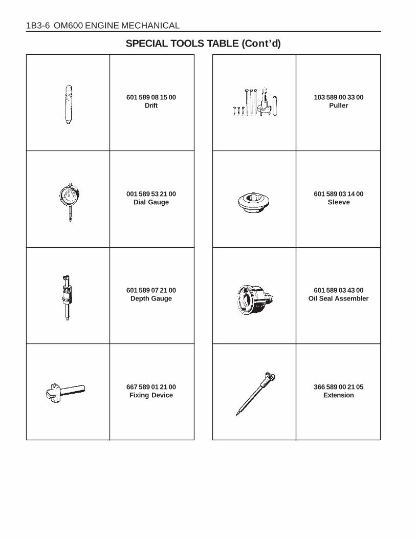
601 589 08 15 00Drift
001 589 53 21 00Dial Gauge
601 589 03 14 00Sleeve
SPECIAL TOOLS TABLE (Cont ’d)
103 589 00 33 00Puller
601 589 07 21 00Depth Gauge
667 589 01 21 00Fixing Device
366 589 00 21 05Extension
601 589 03 43 00Oil Seal Assembler

OM600 ENGINE MECHANICAL 1B3-7
363 589 02 21 00Dial Gauge Holder
000 589 33 33 00Counter Support
000 589 04 14 00Tensioning Strap
SPECIAL TOOLS TABLE (Cont ’d)
116 589 07 15 00Drift
000 589 25 33 00Internal Extractor
102 589 05 33 00Puller
601 589 01 59 00Assembling Board
102 589 03 40 00Magnetic Bar

1B3-8 OM600 ENGINE MECHANICAL
601 589 02 59 00Supporting Bridge
667 589 00 31 00Press Lever
104 589 00 37 00Pliers
SPECIAL TOOLS TABLE (Cont ’d)
667 584 02 63 00Supporting Bar
116 589 06 63 00Magnetic Finger
603 589 01 40 00Holding Wheel
000 589 10 68 00Cylinder Brush
601 589 02 43 00Drift

OM600 ENGINE MECHANICAL 1B3-9
601 589 02 23 00Go/No Go Gauge
105 589 03 15 00Drift (for Intake)
601 589 06 15 00Drift (for Exhaust)
SPECIAL TOOLS TABLE (Cont ’d)
601 589 05 15 00Drift (for Intake)
103 589 02 15 00Drift (for Exhaust)
346 589 00 63 00Super Cooling Box
000 589 21 53 00Reamer (for Intake)
000 589 10 53 00Reamer (for Exhaust)

1B3-10 OM600 ENGINE MECHANICAL
001 589 32 21 00Dial Gauge
001 589 53 21 00Dial Gauge
667 589 02 21 00TDC Pulse Generator
SPECIAL TOOLS TABLE (Cont ’d)
124 589 15 21 00Tester
000 589 58 43 00Chain Assembling
Device
201 589 13 21 00Vacuum Tester
617 589 04 21 00Tester
501 589 73 21 00Vacuum Pump

OM600 ENGINE MECHANICAL 1B3-11
000 589 14 21 00Tester
001 589 65 09 00Serration Wrench
116 589 02 34 00Thread Bolt
SPECIAL TOOLS TABLE (Cont ’d)
000 589 00 68 00Cleaning Set
601 589 05 21 00Looking Screw
617 589 08 21 00Position Sensor
667 589 04 63 00Retaining Plate
601 589 00 08 00Flange

1B3-12 OM600 ENGINE MECHANICAL
MAINTENANCE AND REPAIR
ON-VEHICLE SERVICEENGINE ASSEMBLY

OM600 ENGINE MECHANICAL 1B3-13
4. Remove the radiator drain cock and drain the coolant.
NoticeOpen the coolant reservoir tank cap.
3. Remove the skid plate.
Installation Notice
Tightening Torque 28 - 47 Nm
5. Remove the drain plug (1) and seal (2) from the cylinderblock and drain the coolant completely.
6. After draining, replace the seal and reinstall the drain plug.
Installation Notice
7. Disconnect the lower coolant hose from the radiator.
Tightening Torque 30 Nm
Removal & Installation Procedure1. Disconnect the negative terminal of battery.
2. Remove the hood.

1B3-14 OM600 ENGINE MECHANICAL
9. Loosen the bolt and remove the coolant pipe and coolingfan shroud.
10. Remove the hoses (air intake to intercooler, intercooler tointake duct).
8. Disconnect the upper coolant hose from the radiator.
Tightening Torque 3 -7 Nm
11. Remove the pipes connected to intercooler.

OM600 ENGINE MECHANICAL 1B3-15
15. Remove the air-conditioner lines from the compressor.
NoticeEvacuate the refrigerant before removal.
12. Remove the hose(air cleaner to turbocharger) with blowby hose.
13. Disconnect the air cleaner intake hose and remove the aircleaner cover and element.
14. Disconnect the coolant hose from the water inlet.

1B3-16 OM600 ENGINE MECHANICAL
16. Remove the power steering pump lines.
NoticeCompletely drain the fluid.
17. Disconnect the fuel feed line with prefilter from the feedpump on injection pump.
18. Vehicle with automatic transmission.
Remove the hydraulic lines (19, 20) from oil cooler (2).
19. Disconnect the engine harness.
20. Disconnect the preheating time relay cable.
OM600 ENGINE MECHANICAL 1B3-17
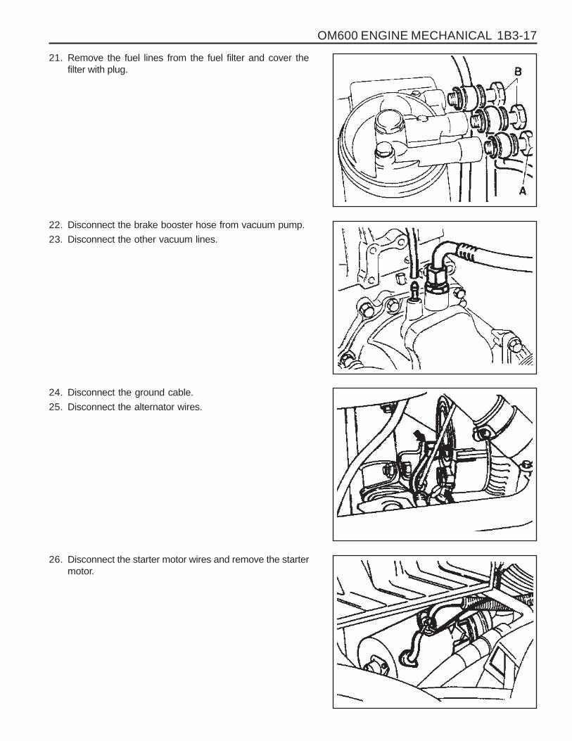
26. Disconnect the starter motor wires and remove the startermotor.
21. Remove the fuel lines from the fuel filter and cover thefilter with plug.
22. Disconnect the brake booster hose from vacuum pump.
23. Disconnect the other vacuum lines.
24. Disconnect the ground cable.
25. Disconnect the alternator wires.

1B3-18 OM600 ENGINE MECHANICAL
27. Disconnect the preheating time relay sensor plug.
28. Disconnect the coolant temperature sensor plug.
29. Disconnect the accelerator cable from the control linkage.
Installation Notice
Tightening Torque 8 - 18 Nm
30. Loosen the connection of control pressure cable (an arrow)used in auto transmission.

OM600 ENGINE MECHANICAL 1B3-19
33. Disconnect the exhaust pipe flange from the exhaustmanifold.
Installation Notice
35. Remove the shift control cable.
36. Remove the transmission.
Tightening TorqueAxle 70 ~ 80 Nm
T/C 81 ~ 89 Nm
Tightening Torque 20 - 34 Nm
31. Separate the exhaust pipe flange from the turbo charger.
Installation Notice
32. Loosen the installing bolt of clutch release cylinder andremove the clutch release cylinder.
Installation Notice
Tightening Torque 30 Nm
Tightening Torque 30 Nm
34. Remove the propeller shaft from the transmission.
Installation Notice

1B3-20 OM600 ENGINE MECHANICAL
37. Loosen the engine mounting bracket nut.
Installation Notice
38. Remove the engine assembly from the vehicle by using ahoist or crane.
39. Installation should follow the removal procedure in thereverse order.
Tightening Torque 50 - 75 Nm

OM600 ENGINE MECHANICAL 1B3-21
POLY V-BELT
1 Nut ............................................................. 23Nm2 Tensioning Lever3 Bolt
4 Spring5 Tensioning Lever6 Poly V-Belt

1B3-22 OM600 ENGINE MECHANICAL
With Air Conditioner
Removal & Installation Procedure1. Remove the nut.
2. Push the tensioning lever in direction of arrow with a rod(F12 ´ 180mm) and pull out the bolt to the rear.
3. Push back the tensioning lever (arrow direction) to releasethe spring tension and remove the belt.
4. Install the poly V-belt beginning at the tensioning pulley (7).
7 Tensioning Pulley8 Crankshaft9 Alternator
10 Coolant Pump11 Guide Pulley12 Power Steering Pump13 Aircon. Compressor
Lengthe of Belt
Length (L)Without Air Conditioner
2,100 mm
2,040 mm
OM600 ENGINE MECHANICAL 1B3-23
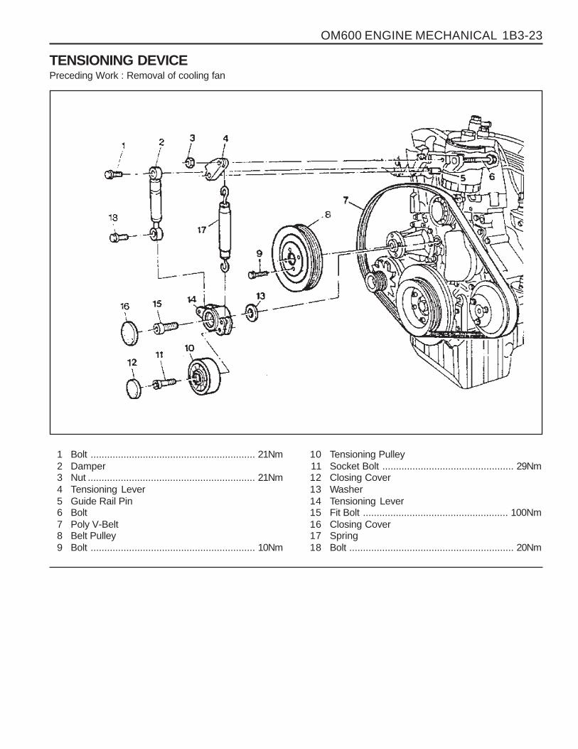
TENSIONING DEVICEPreceding Work : Removal of cooling fan
1 Bolt ............................................................ 21Nm2 Damper3 Nut ............................................................. 21Nm4 Tensioning Lever5 Guide Rail Pin6 Bolt7 Poly V-Belt8 Belt Pulley9 Bolt ............................................................ 10Nm
10 Tensioning Pulley11 Socket Bolt ................................................ 29Nm12 Closing Cover13 Washer14 Tensioning Lever15 Fit Bolt ..................................................... 100Nm16 Closing Cover17 Spring18 Bolt ............................................................ 20Nm

1B3-24 OM600 ENGINE MECHANICAL
Removal & Installation Procedure1. Remove the nut.
Installation Notice
Tightening Torque 10 Nm
2. Push the tensioning lever in direction of arrow with a rod( F12 ´ 180mm ) and push out the bolt to the rear.
3. Push back the tensioning lever to release the spring tensionand remove the belt.
4. Remove the bolt (9) and then remove the belt pulley (8).
5. Remove the bolt (1, 18) and take off the damper (2).
NoticePay attention to installation position of the damper.

OM600 ENGINE MECHANICAL 1B3-25
6. Pull off the tensioning lever (4) from guide rail pin.
7. Remove the spring (17).
Installation NoticeInsert spring (17) with color coding (blue/violet) facing up.
8. Pry off the closing cover (12) and remove the socket bolt(11) and then remove the tensioning pulley (10).
Installation Notice
Tightening Torque 29 Nm
9. Pry off the closing cover (16) and remove the fit bolt (15).
10. Remove the tensioning lever (14) and washer (13).11. Clean thread in the timing case cover and fit bolt.
Installation NoticeApply Loctite on thread of fit bolt.
Tightening Torque 100 Nm
12. Installation should follow the removal procedure in thereverse order.

1B3-26 OM600 ENGINE MECHANICAL
POLY V-BELT ALIGNMENT & INSPECTION
Without Air Conditioner
With Air Conditioner

OM600 ENGINE MECHANICAL 1B3-27
Inspection Procedure� Mark poly V-belt at a clearly visible point with chalk.
� Rotate the engine and check the belt.
NoticeIf one of the following types of damage is found, replacethe belt.
1. Rubber lumps in the base of rips.
2. Dirt or grit ingrained.
5. Cord torn out at the side.
6. Outer cords frayed.
3. Pointed rips.
4. Belt cord visible in the base of rips.

1B3-28 OM600 ENGINE MECHANICAL
7. Belt detached from the base of rip.
8. Splits across the rips.
9. Sections of rip torn out.
10. Splits across several rips.
11. Splits across the back.

OM600 ENGINE MECHANICAL 1B3-29
1 Threaded Ring ........................................ 130 Nm2 Prechamber
PRECHAMBERPreceding Work : Removal of glow plug
Removal of fuel injection nozzle
3 Cylinder Head

1B3-30 OM600 ENGINE MECHANICAL
Tools Required
2. Install the sliding hammer into the prechamber.
Sliding Hammer 667 589 03 63 00
Removal & Installation Procedure1. Using the serration wrench (4), remove the threaded ring
(1).
Serration Wrench 603 589 00 09 00
3. Remove the perchamber (2).
NoticeAfter removing the prechamber, cover over the bores withclean rag.
603 589 00 09 00 Serration Wrench
667 589 03 63 00 Sliding Hammer
4. Inspect the prechamber.
NoticeIf the prechamber seats in the cylinder head are leaking orif the prechambers are replaced, the sealing surfaces inthe cylinder head must be remachined.

OM600 ENGINE MECHANICAL 1B3-31
Assembly Procedure
NoticeIn case the prechambers are reused, inspect theprechambers thoroughly, if the ball pin by heat and fire isbroken, it can not be used.
1. Clean the sealing surface of the prechamber.
2. Insert the prechamber into the cylinder head at the sametime aligning the cam on the collar of the prechambers withthe slots in the cylinder head.
NoticeIf the spacer rings are fitted to the prechambers, the spacerrings should be replaced with rings of the same thickness.
Thickness of Spacer Ring 0.3, 0.6, 1.0 mm
3. Coat the threaded ring with oil and assemble the ring byusing the serration wrench.
Tightening Torque 130 Nm

1B3-32 OM600 ENGINE MECHANICAL
MILLING OF PRECHAMBER SEALING SURFACE
1 Drift2 Sleeve3 Milling Cutter
4 Counter Sink (Special Tool - 601 589 00 66)5 Cylinder Head
Tightening Torque 0.3, 0.6, 1.0 mm
Milling of the Prechamber Sealing Surface
NoticeThe prechamber sealing surface may only be remachinedonce with the cylinder head fitted. It is essential to adhereto the specified projection ‘C’ of the prechamber of 7.6 -8.1mm.
This ensures that the required clearance exists betweenprechamber and piston crown with the piston in TDC. Forthis reason, spacer rings should be inserted on remachinedsealing surfaces.
If a spacer ring is already fitted, or a marking is made on thecylinder head, the cylinder head must be removed and size‘C’ measured if further remachining is necessary on aprechamber sealing surface.
Tools Required
601 589 00 66 00 Counter Sink
667 589 00 23 00 Height Gauge

OM600 ENGINE MECHANICAL 1B3-33
6. Measure the ‘X’ by using a vernier caliper.
7. Mount the turning tool onto the countersink tool and rotateto the right approx. 5 revolutions by applying slight pressure.
1. Remove the injection nozzle.
2. Remove the prechamber.
3. Cover the prechamber bore to avoid any chips droppinginto the combustion chamber.
4. Remove the protective sleeve from the countersink androtate the countersink into the prechamber bore to bemachined as far as the stop.
Counter Sink 601 589 00 66 00
5. Maintain size ‘X’ from the top edge of mandrel to the topedge of the sleeve with the gauge.
Height Gauge 667 589 00 23 00

1B3-34 OM600 ENGINE MECHANICAL
8. Remeasure size ‘X’ and compare it with the firstmeasurement and determine the thickness of spacer ring.
Size before machining 25.7 mm
Size after machining 25.5 mm
Ex
The spacer ring should be selected so that it is at least0.1mm and not more than 0.3mm thicker than themeasured on the sealing surface. In this example, thenecessary thickness of spacer ring should be within0.3 ~ 0.5mm and the thickness of spacer ring to beinstalled is 0.3mm.
9. Remove the countersink tool and clean the chips.
NoticeIf the sealing surface is not completely flat, remachine thesealing surface.
10. emove rag from the prechamber bore and crank the enginewith starter motor to threw out any chips which may havegot into the combustion chamber.
11. Insert the proper spacer ring into the prechamber sealingsurface.
12. Punch a mark on the cylinder head above the prechambersealing surface which has been machined.
13. Install the prechambers.
NoticeIf the cylinder head is removed, the projection ‘C’ ismeasured in place of size ‘X’ and the appropriate size ofspacer ring selected.
Normal Projection (c) 7.6 - 8.1mm

OM600 ENGINE MECHANICAL 1B3-35
TDC (TDC SENSOR BRACKET) SETTINGPreceding Work : Removal of No.1 cylinder prechamber
1 Measuring Device2 Dial Gauge3 Cylinder Head4 Piston ................................................ Set at TDC
Tools Service001 589 32 21 00 Dial Gauge
601 589 07 21 00 Deqth Gauge
667 589 01 21 00 Fixing Device
Notice� The TDC sensor bracket must be adjusted in case of
followings.� When replacing the TDC sensor bracket.
� When replacing the crankshaft, the hub or the vibrationdamper.
� When replacing or installing the timing case cover.
� After engine overhauling.
∗ If the cylinder head is removed, the measuring pin of thedial gauge can be positioned on the piston crown.
This is done by placing the magnetic dial holder on themating surface of the crankcase.

1B3-36 OM600 ENGINE MECHANICAL
Setting (with cylinder head installed)1. Remove the prechamber of No. 1 cylinder.
2. Position the piston of No.1 cylinder at BTDC 10.
3. Install the measuring device into the prechamber bore andposition the dial gauge with a preload of 5mm.
Dial Gauge 001 589 53 21 00Depth Gauge 601 589 07 21 00
4. Slowly rotate the crankshaft in the direction of engine rotationuntil the large pointer on the dial gauge stops (TDC position).
NoticeThe position of TDC is when the large pointer on the dialgauge is stopped before moving back.
5. remove the reinstall the measuring device and position thedial gauge scale at ‘0’.
6. Slowly rotate the crankshaft in the direction of engine rotationuntil the dial gauge has moved back (counterclockwise) by3.65mm.
7. Insert fixing device into the sensor bracket.
NoticeThe pin on the vibration damper must engage into the slotof the fixing device.
Fixing Device 667 589 01 21 00
8. If the pin does not engage, adjust the setting of the sensorbracket by removing and tightening of the sensor bracketbolts.
Tightening Torque 10 Nm
NoticeThe timing mark on the damper must be positioned at ATDC20.

OM600 ENGINE MECHANICAL 1B3-37
CYLINDER HEAD
1 Fuel Injection Pipe ..................................... 18Nm2 Cylinder Head3 Gasket ................................................... Replace4 Bolt ............................................................ 25Nm5 Washer6 Clamp7 Heater Feed Pipe8 Bolt9 Washer
10 Bolt11 Nozzle Washer ....................................... Replace12 Fuel Injection Nozzle ............................ 35-40 Nm13 Hexagon Socket Bolt ................................. 25 Nm14 Washer15 Bolt ........................................................... 25 Nm16 Cylinder Head Bolt .............................. See Table17 Cylinder Head Cover18 Bolt ........................................................... 10 Nm19 Gasket20 Camshaft
21 Camshaft Drive Sprocket ....................... Replace22 Washer23 Bolt(12-Sided).................................. 25Nm + 90°24 Sliding Rail25 Sliding Rail Pin26 Sliding Rail Pin27 Chain Tensioner ....................................... 80 Nm28 Gasket ................................................... Replace29 Cooling Fan .............................................. Check30 Hexagon Socket Bolt ................................. 45 Nm31 Tensioning Lever32 Bolt ........................................................... 25 Nm33 Bolt34 Nut ............................................................ 23 Nm35 Fuel Filter36 Turbo Charger37 Intake Duct38 Gasket ................................................... Replace39 Intake Manifold

1B3-38 OM600 ENGINE MECHANICAL
000 589 77 03 00 Box Wrench Insert
001 589 65 09 00 Socket Wrench Insert
102 589 03 40 00 Magnetic Bar
116 589 02 34 00 Threaded Pin
116 589 03 07 00 T Type Socket Wrench
116 589 20 33 00 Sliding Hammer
601 589 00 10 00 Cylinder Head Bolt Wrench
602 589 00 40 00 Engine Lock
603 589 00 40 00 Counter Holder
Tools Required
Cylinder Bolts (12-sided socket head)(Engine cold)
M8 Cylinder Head Bolts
Tightening Torque
stage1
stage2
stage3
10 Nm
35 Nm
180°
25 Nm
Tightening Sequence for Cylinder Head Bolts
OM 662LA Engine
OM 661LA Engine

OM600 ENGINE MECHANICAL 1B3-39
Length(L) When New
80mm
102mm
115mm
Thread Dia.M10
M10
M10
Max. Length(L)82mm
104mm
117mm
The twelve-sided socket head bolts are tightened with eachstages of torque and torque angle.
It is not necessary to retighten the cylinder head bolts atthe 1000~1500km inspection or after 1000~1500km ofrepairs.
NoticeThe cylinder head may only be removed when the enginehas cooled down. The cylinder head is removed togetherwith the exhaust manifold. As the cylinder head boltsundergo a permanent tightening. They require to bereplaced if they exceed the maximum lengthes indicatedin the table.

1B3-40 OM600 ENGINE MECHANICAL
Disassembly Procedure1. Completely drain the coolant from the radiator and cylinder
block.
2. Remove the cooling fan shroud.
3. Hold the fan with counter holder and remove the bolt andthen remove the cooling fan.
NoticeKeep the fan in vertical position.
Counter Holder 603 589 00 40 00
5. Remove the nut.
6. Remove the nut on the tensioning lever and insert therod(F12 ́ 180mm). By pushing the rod to the arrow direction,pull back the bolt.
7. Push the tensioning lever to the opposite direction to releasethe spring tension and remove the poly V-belt.
4. Remove the bracket oil dipstick tube.

OM600 ENGINE MECHANICAL 1B3-41
8. Remove the air cleaner cover and element and thenremove the air cleaner housing.
9. Remove the oil return hose and plug.
NoticeCover them to prevent chips from coming into.
10. Unscrew the EGR pipe mounting bolts onto the exhaustmanifold.
11. Remove the duct bracket from the cylinder head.
12. Unscrew the intake duct mounting bolts onto the intakemanifold.
13. Separate the connecting rod from the control lever.

1B3-42 OM600 ENGINE MECHANICAL
14. Pull out the accelerator control linkage.
15. Remove the fuel injection line(1) from the fuel injectionnozzle(12).
Box Wrench Inset 000 589 77 03 00
16. Remove the fuel injection line from the fuel injection pump.
Box Wrench Insert 000 589 77 03 00
17. Remove the bracket mounting bolts and then remove thefuel injection line(1).

OM600 ENGINE MECHANICAL 1B3-43
18. Disconnect the booster hose connected to intake manifold.
19. Remove the intake manifold and gasket.
20. Remove the cylinder head cover and gasket with the blow-by gas hose.
21. Disconnect the glow plug cables.

1B3-44 OM600 ENGINE MECHANICAL
22. Remove the cable channel.
23. Disconnect the cables from the glow plug sensor andcoolant temperature sensor.
24. Remove the heater pipe bracket from the oil filter.
25. Pry off the clamp and push the heater feed pipe forwardand then pull out the pipe.

OM600 ENGINE MECHANICAL 1B3-45
26. Disconnect the fuel lines from the fuel filter.
27. Disconnect the fuel lines from the injection pump.
28. Remove the fuel filter(35).
29. Remove the fuel injection nozzle(12) and nozzlewasher(11).
Socket Wrench Insert 001 589 65 09 00

1B3-46 OM600 ENGINE MECHANICAL
30. Rotate the crankshaft and set the no.1 cylinder at TDC.
NoticeDo not rotate the crankshaft to the opposite direction ofengine revolution.
31. Place alignment marks on the camshaft gear and timingchain.
32. Ensure that the camshaft and the bearing cap markingare aligned.
33. Remove the starter motor and install the engine lock ontothe flywheel ring gear.
Engine Lock 602 589 00 40 00

OM600 ENGINE MECHANICAL 1B3-47
34. Remove the turbocharger.
35. Remove the exhaust manifold and gasket.
36. Remove the chain tensioner and seal.
37. Remove the bolt and separate the drive sprocket(21).
NoticeDuring removal, be careful not to drop the sprocket andchain into the timing case.
Carefully pull off the chain and then pull out the sprocket.

1B3-48 OM600 ENGINE MECHANICAL
38. Remove the camshaft bearing cap bolts according to thenumerical sequence.
NoticeRemove the No.1 bolts first and then remove the No. 2bolts. Do not remove the bolts at a time completely butremove them step by step evenly or camshaft can beseriously damaged.
OM662LA
39. Remove the bearing caps and then pull out thecamshaft(20) upward.
NoticeBe careful not to miss the locking washer.
40. Remove the locking washer.
NoticeCheck the locking washer and replace if necessary.
OM661LA

OM600 ENGINE MECHANICAL 1B3-49
41. Remove the bolt(32).
42. Separate the spring and pull out the tensioning lever(31).
43. Pry off the closing cover. Remove the bolt and then removethe idle pulley.
44. Using the sliding hammer(36) and the threaded pin(37),pull out the sliding rail pins(25, 26) and remove the slidingrail(24).
Sliding Hammer 116 589 20 33 00Threaded Pin 116 589 02 34 00

1B3-50 OM600 ENGINE MECHANICAL
OM 662LA
46. Disconnect the vacuum pipe from thermo valve.
47. Remove the socket bolts(13) of the chain box.
T Type Socket Wrench 116 589 03 07 00Magnetic Bar 102 589 03 40 00
48. Remove the cylinder head bolts in numerical se-quence.
Cylinder Head Bolt Wrench 601 589 00 10 00
45. Remove the vacuum line from the vacuum pump.

OM600 ENGINE MECHANICAL 1B3-51
49. Remove the cylinder head(2) and gasket(3).
OM 661LA

1B3-52 OM600 ENGINE MECHANICAL
Length(L)
Assembly Procedure1. Replace the cylinder head gasket.
2. Install the cylinder head onto the crankcase.
NoticeAlign the cylinder head holes with the guide pins.
3. Measure the length(L) of cylinder head bolts.
NoticeIf the max. length is exceeded, replace the bolts.
Thread Dia. Max. Limit(L)
M10
M10M10
80mm
102mm115mm
82mm
104mm117mm
when new
4. Coat the head contact surface of bolts and thread with oiland insert them as shown.
- Cylinder head bolts arrangementBore
1 ........................................... M10 × 80
2 ........................................... M10 × 102
3 ........................................... M10 × 115
4 ........................................... M 8 × 50
5 ........................................... M 8 × 80
OM662LA

OM600 ENGINE MECHANICAL 1B3-53
5. Tighten the cylinder head bolts to specified torque andtorque angle.
OM 662LAOM 661LA
6. Install the socket bolts in the chain box.
Tightening Torque 25 Nm
Stage 1
Stage 2
Torque angle
Wait for
Torque angle
15 Nm
35 Nm
90°
10 minutes
90°
7. Connect the vacuum pipe to the thermo valve.

1B3-54 OM600 ENGINE MECHANICAL
8. Connect the vacuum lines to the vacuum pump.
9. Install the fuel filter and connect the pipe.
Tightening Torque 25 Nm
NoticeBe careful not to be confused the connections and hoses.
10. Connect the fuel pipe to the injection pump.
11. Install the sliding rail(24) and insert the sliding rail pins(25,26).
NoticeApply sealing compound on the each collar of the slidingrail pins.
Sliding Hammer 116 589 20 33 00Threaded Pin 116 589 02 34 00

OM600 ENGINE MECHANICAL 1B3-55
12. Install the idle pulley and fit the closing cover.
Tightening Torque 25 Nm
13. Insert the tensioning lever(31) and install the spring.
14. Install the damper.
Tightening Torque 23 Nm
NoticeInsert the tensioning lever bolts onto the mounting hole.
15. Insert the locking washer.
16. Inspect the valve tappet and check that the tappet movessmoothly.

1B3-56 OM600 ENGINE MECHANICAL
17. Coat the camshaft with oil and install the camshaft on thecylinder head to be TDC mark(arrow) upward.
18. Measure the axial end play of the camshaft.
End Play 0.06 - 0.21mm
NoticeIf out of standard, adjust it with the proper thickness oflocking washer.
19. Install the bearing caps on the camshaft according to thenumber on the caps.
20. Tighten the bearing cap bolts according to the numericalsequence.
Tightening Torque 25 Nm
NoticeTighten the No. 1 bolts(light arrow) first and then tightenthe No. 2 bolts(dark arrow) stage by stage.
OM662LA
OM661LA

OM600 ENGINE MECHANICAL 1B3-57
21. Position the camshaft on marking and install the camshaftsprocket.
NoticeAlign the alignment marks on the chain and sprocket.
23. Install the camshaft sprocket bolt.
22. Check the TDC position of the crankshaft.
Tightening Torque 25 Nm + 90°

1B3-58 OM600 ENGINE MECHANICAL
24. Install the exhaust manifold and gasket.
25. Install the turbocharger.
26. Install the exhaust pipe onto the turbocharger.
Tightening Torque 25 Nm
NoticeMeasure the max. length ‘L’ and replace the bolt if it exceeds53.6mm.

OM600 ENGINE MECHANICAL 1B3-59
27. Replace the seal and then install the chain tensioner.
Tightening Torque 80 Nm
28. Remove the engine lock.
29. Insert the nozzle washer into the hole to face round partdownward.
30. Install the fuel injection nozzle.
Tightening Torque 40 Nm
31. Connect the fuel hose.
32. Install the cable channel and connect the cables to glowplugs.

1B3-60 OM600 ENGINE MECHANICAL
35. Connect the wires to the coolant temperature sensor andthe glow plug sensor.
36. Replace the intake manifold gasket.
37. Install the intake manifold.
Tightening Torque 25 Nm
33. Replace the gasket and install the cylinder head cover.
Tightening Torque 10 Nm
34. Install the blow-by hose.

OM600 ENGINE MECHANICAL 1B3-61
38. Replace the O-ring of heater feed pipe and install it to thecylinder head.
NoticeFor installation, clean the hole.
39. Install the bracket of heater feed pipe to the oil filter.
40. Install the fuel pipe and the accelerator control linkage.
41. Connect the fuel lines to the injection nozzles and to theinjection pump.
Box Wrench Insert 000 589 77 03 00
Tightening Torque 18 Nm

1B3-62 OM600 ENGINE MECHANICAL
43. By inserting a rod into the tensioning lever upper hole andpulling the rod, install the bolt and then tighten the nut.
44. Install the oil dipstick tube bracket.
Tightening Torque 10 Nm
45. Hold the cooling fan with the counter holder and tightenthe bolt.
42. Install the poly V-belt.
NoticeBe careful not to contaminate the belt.
Tightening Torque 23 Nm

OM600 ENGINE MECHANICAL 1B3-63
TIMING CASE COVERPreceding Work : Removal of the cooling fan
Rmoval of the V-belt tensioning deviceRemoval of the vibration damper and hubRemoval of the alternator
1 Bolt ............................................................ 10Nm2 Cylinder Head Cover3 Gasket ................................................... Replace4 Socket Bolt ................................................ 25Nm5 Fuel Filter6 Square Nut7 Oil Pan8 Socket Bolt ................................................ 10Nm9 Bolt .................................................... M6 : 10Nm
M8 : 23Nm10 Power Steering Pump11 Bolt12 Belt Pulley
13 Bolt ............................................................ 32Nm14 Timing Case Cover15 Bolt ............................................................ 23Nm16 Alternator Bracket17 Bolt ............................................................ 45Nm18 Bolt ............................................................ 25Nm19 Bolt ............................................................ 10Nm20 Closing Cover21 Socket Bolt ................................................ 23Nm22 Guide Pulley23 Bolt .............................................................. 9Nm24 Guide Pulley Bracket25 Nut ............................................................. 23Nm

1B3-64 OM600 ENGINE MECHANICAL
8. Remove the guide pulley bracket (24).
Tools Required116 589 03 07 00 Socket Wrench
Removal Procedure1. Remove the fan clutch and cooling fan belt pulley.
2. Drain the engine oil completely.
3. Remove the oil dipstick tube bracket bolts.
4. Remove the crankshaft pulley.
5. Loosen the bolt (1) and then remove the cylinder head cover(2) and gasket.
6. Remove the vacuum pump.
7. Detach the closing cover (20). Remove the bolts(21) andthen remove the guide pulley (22).

OM600 ENGINE MECHANICAL 1B3-65
11. Remove the alternator bracket (16).
9. Disconnect the pipes of power steering pump and removethe belt pulley.
NoticeBe careful not to lose the key.
10. Remove the nut and pull out the bolt and then remove thepower steering pump.
12. Remove the fuel filter.

1B3-66 OM600 ENGINE MECHANICAL
18. Remove the timing case cover (19) bolts and then removethe timing case cover (14).
NoticeBe careful not to damage the cylinder head gasket or oilpan gasket.
13. Remove the camshaft.
14. Remove the socket bolts(4) in the chain box.
Socket Wrench 115 589 03 07 00
15. Remove the injection pump.
NoticeSee the ‘Removal of fuel injection pump’.
16. Remove the oil pan bolts (8, 9) in the area of the timingcase cover (14).
17. Slightly loosen the remaining oil pan bolts.

OM600 ENGINE MECHANICAL 1B3-67
Installation Procedure1. Thoroughly clean the sealing surface and apply sealant.
2. Install the timing case cover.
NoticeBolts arrangement1.M6 x 60
2.M6 x 70
3.M6 x 40
3. Tighten the socket bolts in the chain box.
Tightening Torque 10 Nm
Tightening Torque 23 Nm
4. Tighten the oil pan bolts.
Tightening Torque10 Nm
10 Nm
23 Nm
Socket bolt
M6 bolt
M8 bolt

1B3-68 OM600 ENGINE MECHANICAL
Tightening Torque25 Nm
5. Install the flange, vibration damper and crankshaft beltpulley.
NoticeReplace front radial seal if necessary.
6. Install the alternator bracket.
25 Nm
Front
Side
7. Install the alternator
Tightening TorqueUpper - 25 Nm
Low - 25 Nm
8. Install the cylinder head cover.
Tightening Torque 10 Nm
9. Tighten the injection pump mounting bolts.
Tightening Torque 23 Nm

OM600 ENGINE MECHANICAL 1B3-69
10. Install the fuel filter.
11. Install the vacuum pump.
12. Install the power steering pump.
13. Install the power steering pump pulley.
Tightening Torque 25 Nm
Tightening Torque 10 Nm
Tightening Torque 23 Nm
Tightening Torque 32 Nm
14. Install the guide pulley bracket.
Tightening Torque 9 Nm

1B3-70 OM600 ENGINE MECHANICAL
15. Install the guide pulley (22) and fit the closing cover (20).
16. Replace the gasket (3) and install the cylinder head cover(2).
17. Install the cooling fan belt pulley and fan clutch.
18. Install the belt tensioning device and then install the belt.
19. Install the cooling fan.
20. Fill the engine oil and check oil leaks by running the engine.
Tightening Torque 23 Nm
Tightening Torque 10 Nm

OM600 ENGINE MECHANICAL 1B3-71
CRANKSHAFT END COVERPreceding Work : Removal of flywheel and driven plate.
1 Crankshaft Flange2 End Cover.............................. Clean, Loctite 5733 Bolt ......................................... 10Nm, Loctite 573
4 Radial Seal ............................................ Replace5 Dowel Sleeve6 Bolt ......................................... 10Nm, Loctite 573

1B3-72 OM600 ENGINE MECHANICAL
Tools Required601 589 03 43 00 Oil Seal Assmbler
Removal Procedure1. Remove the bolts (3, 6) from end cover, By pulling out the
lugs (arrow), remove the cover.
NoticeBe careful not to damage the oil pan gasket.
2. Remove the radial seal (4) with care not to damage thesealing surface.
Installation Procedure1. Thoroughly clean the sealing surface of end cover and apply
Loctite 573.2. Clean the groove of radial seal.
3. Apply Loctite 573 on the bolts and install the end cover.
Tightening Torque 10 Nm
NoticeBe careful not to damage the oil pan gasket.
4. Install the inner oil seal assembler to the crankshaft flange.
Oil Seal Assembler 601 589 03 43 00

OM600 ENGINE MECHANICAL 1B3-73
NoticeThe sealing lip of the repair radial seal is offset to the insideby 3mm to ensure that it does not run in any groove whichthe standard radial seal may have left on the crankshaftflange.
7. Install the outer oil seal assembler on he seal and bytightening the bolts, press the radial seal into the end coveras far as the stop.
NoticeThe seal must be positioned exactly at right angles in theend cover to ensure that it provides a proper seal.
Oil Seal Assembler 601 589 03 43 00
A Standard Radial SealB Repair Radial Seal
5. Coat a little oil on the sealing lip of new radial seal andcontacting surface.
NoticeDon’t use grease.
6. Insert the new radial seal (4) onto the oil seal assembler(7).

1B3-74 OM600 ENGINE MECHANICAL
VIBRATION DAMPER AND HUBPreceding Work : Removal of the cooling fan
Removal of poly V-belt
1 Bolt ............................................................ 10Nm2 Cooling Fan Belt Pulley3 Socket Bolt ................................................ 23Nm4 Crankshaft Belt Pulley5 Vibration Damper
6 Bolt ................................................ 200Nm + 90°7 Washer8 Straight Pin9 Hub
10 Oil Pan

OM600 ENGINE MECHANICAL 1B3-75
Sectional View
3 Socket Bolt4 Crankshaft Belt Pulley5 Vibration Damper6 Bolt7 Washer8 Straight Pin
NoticeThe mounting position of vibration damper is fixed by straightpin (8).
Tools Required602 589 00 40 00 Engine Lock
103 589 00 30 00 Puller
9 Hub11 Radial Seal12 Timing Gear Case Cover13 Key14 Crankshaft Sprocket16 Crankshaft

1B3-76 OM600 ENGINE MECHANICAL
Removal Procedure1. Remove the starter motor and install the engine lock into
the wheel ring gear.
Engine Lock 602 589 00 40 00
2. Remove the poly V-belt.
3. Remove the cooling fan.
NoticeKeep the fan in vertical position.
4. Remove the cooling fan belt pulley (2).
5. Place alignment marks (arrow) on the vibration damper (5)and crankshaft belt pulley (4).
6. Remove the timing sensor bracket.
NoticeRemove if necessary.

OM600 ENGINE MECHANICAL 1B3-77
7. Remove the socket bolts (3) and then remove the beltpulley (4) and vibration damper (5).
8. Remove the washer and bolt.
9. Remove the hub by using a puller.
Puller 103 589 00 33 00
10. Replace the radial seal.

1B3-78 OM600 ENGINE MECHANICAL
Installation Procedure1. Install the hub.
NoticeExactly align the woodruff key and the groove of hub (arrow).
2. Install the washer (7) and tighten the bolt (6).
Washer (new) : 1 EA 200 Nm + 90°
3. Install the vibration damper.
NoticeExactly align and insert onto the straight pin.
4. Install the belt pulley.
Tightening Torque 25 Nm
NoticeAlign the alignment marks.

OM600 ENGINE MECHANICAL 1B3-79
5. Install the timing sensor bracket.
NoticeSee the ‘TDC setting’.
6. Install the cooling fan pulley.
Tightening Torque 10 Nm
7. Install the cooling fan.
8. Install the fan belt.
9. Remove the engine lock.

1B3-80 OM600 ENGINE MECHANICAL
CRANKSHAFT FRONT RADIAL SEAL
1 Radial Seal2 Timing Case Cover
Tools Required601 589 03 14 00 Sleeve
3 Woodruff Key

OM600 ENGINE MECHANICAL 1B3-81
NoticeThe sealing lip of the repair radial seal is offset to the insideby 2mm to ensure that is does not run in any groove whichthe standard radial seal may have left on the crankshaftflange.
A Standard Radial SealB Repair Radial Seal
Replacement Procedure1. Pull out the radial seal (1) and be careful not to damage the
sealing surface of timing case cover.
2. Thoroughly clean the mounting bore of the radial seal.
3. Coat a little oil on the sealing lip of new radial (1) and contactsurface.
NoticeDon’t use grease.
4. Install the radial seal (1) by using a sleeve (4).
NoticeAlign the groove of sleeve and woodruff key(arrow).
Sleeve 601 589 03 14

1B3-82 OM600 ENGINE MECHANICAL
CRANKSHAFT BALL BEARING
1 Spacer2 Cover ......................................... Replace
NoticeManual transmission only.
Tools Required000 589 33 33 00 Counter Support
000 589 25 33 00 Internal Extractor
Removal & Installation Procedure1. Remove the manual transmission.
2. Using a puller, pull out the locking ring and ball bearingtogether.
Counter Support 000 589 33 33 00Internal Extractor 000 589 25 33 00
3. Apply Loctite 241 on the new ball bearing and then insertthe ball bearing to be stopped at the spacer ring by using aproper mandrel.
3 Ball Bearing4 Bolt ....................................... 45Nm + 90°

OM600 ENGINE MECHANICAL 1B3-83
CRANKSHAFTPreceding Work : Removal of the end cover
Removal of the pistonRemoval of the crankshaft sprocket
3 Crankshaft Main Bearing Shells (Upper)4 Trust Bearings (Upper)5 Crankshaft6 Crankshaft Main Bearing Shells (Lower)
7 Thrust Bearings (Lower)8 Crankshaft Bearing Cap9 Crankshaft Bearing Cap (Fit Bearing)
10 12-sided Stretch Bolts .......................55Nm + 90°
Tools Required001 589 53 21 00 Dial Gauge
363 589 02 21 00 Dial Gauge Holder
366 589 00 21 05 Extension

1B3-84 OM600 ENGINE MECHANICAL
3 Crankshaft Main Bearing Shells (Upper)4 Thrust Bearings (Upper)5 Crankshaft6 Crankshaft Main Bearing Shells (Lower)7 Thrust Bearings (Lower)
A Radial BearingsB Radial and Axial Bearings (Thrust Bearing)
NoticeThe gaps between the bearing shell and bore andbetween the bearing shell and journal are differenteach other. Refer to service data.
Thrust Washer and Bearing Arrangement
OM662LA Engine

OM600 ENGINE MECHANICAL 1B3-85
3 Crankshaft Main Bearing Shells (Upper)4 Thrust Bearings (Upper)5 Crankshaft6 Crankshaft Main Bearing Shells (Lower)7 Thrust Bearings (Lower)
A Radial BearingsB Radial and Axial Bearings (Thrust Bearing)
NoticeThe gaps between the bearing shell and bore andbetween the bearing shell and journal are differenteach other. Refer to service data.
OM661LA Engine

1B3-86 OM600 ENGINE MECHANICAL
24.500 - 24.533
24.600 - 24.633
24.700 - 24.733
24.900 - 24.933
25.000 - 25.033
New
Limit
New
Limit
Radial clearances
Axial clearances
Crankshaft bearingjournal diameter
Crankshaft Standard and Repair Sizes
Standard size 50.950 - 57.965
journal width24.500 - 24.533
24.600 - 24.633
24.700 - 24.733
24.900 - 24.933
25.000 - 25.033
-
Thrust bearingjournal diameter
47.950 - 47.965
Thrust bearing
47.700 - 47.715
47.450 - 47.650
47.200 - 47.215
46.950 - 46.965
57.500 - 57.715
57.450 - 57.465
57.200 - 57.215
56.950 - 56.965
Repair size 1
Repair size 2
Repair size 3
Repair size 4
Bearing Clearances
Thrust bearing Crankshaft bearing
0.026 - 0.068
Max. 0.080
-
-
0.027 - 0.051
Max. 0.070
0.100 - 0.254
Max. 0.300
Matching Fit Bearing Journal Width to Thrust Bearings
Fit bearing journal width Thrust bearings thickness
2.15
2.20
2.25
2.35
2.40
Notice� Measure crankshaft axial clearance and adjust with proper thrust Bearing.
� The same thickness of washer must be installed on both sides of the fit bearing.
mm
mm
mm

OM600 ENGINE MECHANICAL 1B3-87
bearing shell
Matching Crankshaft Bearing Shells to Basic Bearing Bore in Crankshaft
Matching Crankshaft Bearing Shells to Basic Bearing Journal of Crankshaft
Marking of basic bearing bore in lower Color code of relevant crankshaftparting surface
1 punch mark or blue
2 punch marks or yellow
3 punch marks or red
bearing shellBlue or white-blue
Yellow or white-yellow
Red or white-red
Marking of bearing journals on crank webs Color code of relevant crankshaft
Blue or white-blue
Yellow or white-blue
Red or white-blue
Blue or white-blue
Yellow or white-yellow
Red or white-red

1B3-88 OM600 ENGINE MECHANICAL
Removal & Installation Procedure1. Remove the bearing cab bolt.
2. Remove the bearing caps (8).
NoticeThe crankshaft bearing caps are marked with stampednumbers. Remove the bearing cap from the vibrationdamper side.
3. Remove the crankshaft bearing caps (9) and lower thrustbearings (7).
4. Remove the lower thrust bearings (6) from the bearing cap(9).
5. Remove the crankshaft (5).
6. Remove the upper thrust bearings(4).
7. Remove the upper bearing shells (3) from crankcase.

OM600 ENGINE MECHANICAL 1B3-89
14. Measure crankshaft bearing journal diameter (F).
NoticeWhen measured in A and B, the runout should not exceed0.010mm.
8. Thoroughly clean the oil gallery.
9. Select a proper new bearing shells with reference to table.
10. Coat the new bearing shells with oil and insert into thecrankcase and into the crankshaft bearing caps.
NoticeDo not mix up upper and lower crankshaft bearing shells.
11. Install the bearing caps according to marking and tightenthe 12-sided stretch bolts.
Tightening Torque 35 - 40 Nm
NoticeNo. 1 is vibration damper side.
12. Measure crankshaft bearing diameters (E).
Extension 366 589 00 21 05
13. Measure at 3 points (A, B and C) and if the average valueof B and C is less than A’ s value, the average value of Band C is the mean value and if more than A’ s value, A’ svalue is the mean value.

1B3-90 OM600 ENGINE MECHANICAL
15. Measure radial clearance of crankshaft bearing (G).
Clearance ‘G’ 0.027 - 0.051mm
NoticeIf ‘G’ is out of standard, replace the bearing shells andadjust the radial clearance of crankshaft bearing.
Example) Measured value ‘E’ = 57.700mm
Measured value ‘F’ = 57.659mm
Clearance ‘G’ = 0.041mm
16. Remove the crankshaft bearing cap.
17. Measure width of thrust bearing journal (H) and adjust withproper thrust bearings (see table).
NoticeThe same thickness of thrust washers should be installedon both sides of the thrust bearing.
18. Coat the upper thrust bearing (4) with oil and insert intothe crankcase so that the oil grooves are facing the crankwebs (arrow).
19. Coat the lower thrust bearing (7) with oil and insert into thecrankshaft bearing cap so that the oil grooves are facingthe crank webs (arrow).
NoticeThe retaining lugs should be positioned in the grooves(arrow).

OM600 ENGINE MECHANICAL 1B3-91
NoticeIf the max. length of bolts(L) exceed 63.8mm, replace them.
19. Coat the new crankshaft with engine oil and place it on thecrankcase.
20. Install the crankshaft bearing caps according to markingand tighten the bolts.
Tightening Torque 55 Nm + 90°
NoticeInstall from No. 1 cap.
22. Rotate the crankshaft with hand and check whether itrotates smoothly.
23. Measure crankshaft bearing axial clearance.
Clearance 0.100 - 0.245mm
NoticeIf the clearance is out of standard, adjust the axial clearanceof crankshaft bearing by replacing the thrust washers.
Dial Gauge 001 589 53 21 00Dial Gauge Holder 363 589 02 21 00
NoticeThe same thickness of thrust washers should be installedon both sides of the thrust bearing.

1B3-92 OM600 ENGINE MECHANICAL
28. Remove the connecting rod bearing cap.
29. Install the piston.
30. Rotate the crankshaft by hand and check whether it rotatessmoothly.
31. If the bearings are damaged,
- replace the oil presser relief valve.- clean the oil pump and oil filter housing carefully andreplace the hose if necessary.
NoticeAfter assembling the engine, check the camshaft timing,adjust the start of fuel injection and check the TDC sensorbracket setting.
32. Fill oil and run the engine and then check the oil pressureand oil level.
NoticeInstall the original oil filter element and then change theengine oil and oil filter element after 1,000 - 1,500km.
27. Measure the radial clearance (L) of the connecting rodbearing.
Example) Measured value ‘J’ = 47.700mmMeasured value ‘K’ = 47.653mm
Clearance ‘L’ = 0.047mm
Radial Clearance ‘L’ 0.026 - 0.068mm
NoticeIf the clearance is out of standard, adjust the radialclearance of connecting rod bearing by replacing theconnecting rod bearing shells.
26. Measure connecting rod bearing journal diameter (K).
NoticeRefer to measurement of the crankshaft bearing journaldiameter.
24. Insert the new connecting rod bearing shells into theconnecting rod and connecting rod bearing cap and tightenthe 12-sided stretch bolts (11).
25. Measure inner diameter of connecting rod bearing.
Tightening Torque 40 Nm + 90°

OM600 ENGINE MECHANICAL 1B3-93
FLYWHEELPreceding Work : Removal of the transmission
Removal of the clutch
1 Oil Pan2 Straight Pin3 Flywheel
4 12-Sided Stretch Bolt ............Check, 45Nm + 90°5 Drive Plate (Automatic Transmission)6 Flywheel (Automatic Transmission)

1B3-94 OM600 ENGINE MECHANICAL
� Manual transmission flywheel
� Automatic transmission flywheel
OM661LAOM662LA

OM600 ENGINE MECHANICAL 1B3-95
3. Remove the flywheel (3), if equipped with manualtransmission.
Installation NoticeCorrectly align the position of dowel pin (2).
Tools Required602 589 00 40 00 Engine Lock
Removal & Installation Procedure1. Install the engine lock.
Engine Lock 602 589 02 40 00
2. Remove the 12-sided stretch bolts (4).
Installation Notice
Tightening Torque 45 Nm + 90°
NoticeIf the length ‘L’ of bolts exceeds 22.5mm, replace the bolts.

1B3-96 OM600 ENGINE MECHANICAL
4. Remove the flywheel (6) and driven plate (5), if equippedwith automatic transmission.
Installation NoticeCorrectly align the position of dowel pin (2).
5. Installation should follow the removal procedure in thereverse order.

OM600 ENGINE MECHANICAL 1B3-97
MACHINING OF FLYWHEEL
1 Flywheel
Machining of Flywheel
NoticeFlywheels which have scorch marks, scoring or cracks inthe clutch surface should be machined by grinding orprecision-turning. If the scores or cracks are severe thanpermissible specifications, replace the flywheel.
� When machining the clutch surface ‘A’, the mountingsurface (B) for the clutch pressure plate should also bemachined in accordance with ‘A’ to keep the distance ‘a’.
� Do not machine under ‘b’ value.
� When machining, fix the flywheel exactly not to exceed thestandard runout.
OM662LAOM662LA
Max. axial runout
Distance ‘a’
New
Repair up to
19.3 - 19.5 mm
16.6 mm
15.6 mm
0.05 mm
Distance ‘b’

1B3-98 OM600 ENGINE MECHANICAL
FLYWHEEL RING GEARPreceding Work : Removal of flywheel
1 Ring Gear2 Flywheel
3 Centering Collar Diameter
Tools Required001 589 53 21 00 Dial Gauge
363 589 02 21 00 Dial Gauge Holder

OM600 ENGINE MECHANICAL 1B3-99
Diameter ‘a’ 275 + 0.5mm
Replacement Procedure1. Drill a hole into the ring gear (1) (arrow) and snap
with a chisel.
2. Thoroughly clean the collar surfaces of ring gear.
3. Measure diameter (a) of centering collar.
NoticeIf out of standard, replace the flywheel.
4. Heat up the new ring gear up to 220°C by using aheating device.
NoticeUse temperature measuring chalk.
5. Install the new ring gear (1) onto the flywheel by using adrift.

1B3-100 OM600 ENGINE MECHANICAL
6. Measure axial runout of ring gear (1) on a surface plate.
Limit Max. 0.4mm
NoticeFor correct measurement, put the flywheel on the flatmeasuring board.
Dial Gauge 001 589 53 21 00Dial Gauge Holder 363 589 02 21 00

OM600 ENGINE MECHANICAL 1B3-101
HYDRAULIC VALVE CLEARANCE COMPENSATION ELEMENT CHECK
1 Cylinder Head Cover2 Bolt ............................................................ 10Nm3 Gasket ................................................... Replace
4 Valve Tappet5 Cylinder Head

1B3-102 OM600 ENGINE MECHANICAL
Checking
NoticeThe noise which continues short time during short travel(frequent starting of the engine) or engine starting after along time storage is normal operating conditions. So, it doesnot need to be repaired. Determine the malfunctions in valveclearance compensation device with noise through followingtests. If defective, replace as respectively.
1. Run the engine at more than 3000rpm for approx. 4 minutes.
2. Stop the engine. After 5minutes, check the engine oil leveland adjust if necessary.
3. Remove the cylinder head cover.
4. Check the valve tappets at TDC position of each cylinders.
5. Using a drift, lightly press the valve tappet and measureclearance between the cam and valve tappet.
NoticeIf the clearance exceeds 0.4mm, replace the valve tappet.
6. If a valve tappet moves down too far in comparison to theothers, replace the valve tappet.
7. Rotate the engine and check the remaining valve tappets.
Notice� Unnecessary rotation of the engine will damage the valve
tappets.
� Do not rotate the engine by using the camshaft sprocketbolt or to the opposite direction of the engine rotation.

OM600 ENGINE MECHANICAL 1B3-103
VALVE TAPPETSPreceding Work : Removal of camshaft
1 Valve Tappet2 Cylinder Head3 Oil Gallery
4 Seal ....................................................... Replace5 Screw Plug
Tools Required102 589 03 40 00 Magnetic Bar

1B3-104 OM600 ENGINE MECHANICAL
Replacement Procedure1. Pull out the valve tappet (1).
Magnetic Bar 102 589 03 40 00
2. Remove the plug (5) and blow compressed air into the oilgallery (3). At this time, check that the outlet bores(arrow)at the seat of the valve tappet are clear.
3. Replace the seal (4) and tighten the plug (5).
4. Insert the new valve tappet.
NoticeCoat the valve tappet with oil.

OM600 ENGINE MECHANICAL 1B3-105
VALVE SPRINGS CHECKPreceding Work : Removal of valve spring
1 Valve Spring
Service Data
Outer diameter
33.1mm
Wire diameter
4.20mm
Free length
50.0mm
At preloaded
Length Tension (new)
680 - 740N27mm
Limit
612N
2 Spring Scale

1B3-106 OM600 ENGINE MECHANICAL
VALVE SPRINGS (CYLINDER HEAD REMOVED)Cylinder Head Removed
1 Valve Tappet2 Valve Cotters3 Spring Retainer4 Valve Spring ........... Check, replace if necessary5 Cylinder Head
6 Stud Bolt .................................................... 12Nm7 Washer8 Nut .............................................. Replace, 25Nm9 Exhaust Manifold

OM600 ENGINE MECHANICAL 1B3-107
Removal & Installation Procedure1. Remove the nuts (8) uniformly and then remove the washer
(7), exhaust manifold (9) and gasket.
Installation NoticeCheck the stud bolt (6) for damage and replace if necessary.
Tighten Torque 12 Nm
Tighten Torque 25 Nm
Tools Required102 589 03 40 00 Magnetic Bar
116 589 06 63 00 Magnetic Finger
601 589 01 59 00 Assembling Board
601 589 02 59 00 Supporting Bridge
667 589 00 31 00 Press Lever
Replace the gasket and tighten the nuts (8).
2. Install the assembling board (11) to the cylinder head with 4cylinder head blots (10).
Assembling Board 601 589 01 59 00
3. Pull out the valve tappet (1) with magnetic bar (12).
NoticePlace the valve tappets upside down (open end upward).
Magnetic Bar 102 589 03 40 00
4. Install the supporting bridge (13) on the cylinder head (5).
Supporting Bridge 601 589 02 59 00

1B3-108 OM600 ENGINE MECHANICAL
5. Using the press lever (14), press the spring retainerdownward and remove the valve cotters (2) with magneticfinger (15).
NoticeBe careful not to damage guide bore of the valve tappet.
Press Lever 667 589 00 31 00Magnetic Finger 116 589 06 63 00
6. Remove the spring retainer (3) and spring (4).
Installation NoticeInstall the valve spring with the color coding (arrow) facingdown.
7. Check the valve spring and replace if necessary.
8. Installation should follow the removal procedure in thereverse order.

OM600 ENGINE MECHANICAL 1B3-109
VALVE SPRINGS (CYLINDER HEAD INSTALLED)Preceding Work : Removal of camshaft
1 Valve Tappet2 Valve Cotters3 Spring Retainer
4 Valve Spring .......... Check, replace if necessary5 Timing Chain6 Cylinder Head
NoticeRemove the valve springs only when the piston is at TDC.
Tools Required102 589 03 40 00 Magnetic Bar
116 589 06 63 00 Magnetic Finger
603 589 01 40 00 Holding Wheel
667 589 00 31 00 Press Lever
667 589 02 63 00 Supporting Bar

1B3-110 OM600 ENGINE MECHANICAL
5. Using the press lever (9), press the spring retainer(3)downward and remove the valve cotters (2) with magneticfinger (10).
NoticeBe careful not to damage guide bore of the valve tappet.
Press Lever 667 589 00 31 00Magnetic Finger 116 589 06 63 00
Removal & Installation Procedure1. Remove the valve tappet (1) with magentic lifter.
NoticePlace the valve tappets upside down (open end upward)
Magentic Liter 102 589 03 40 00
2. Install the holding wheel (7) into the timing chain of camshaftsprocket piston.
Holding Wheel 603 589 01 40 00
3. Position the piston of relevant cylinder at TDC.
4. Install the supporting bar (8).
Supporting Bar 667 589 02 63 00

OM600 ENGINE MECHANICAL 1B3-111
6. Remove the spring retainer(3) and spring (4).
7. Check the valve spring and replace if necessary.
8. Insert valve spring (4) with the color coding (arrow) facingdown and insert valve spring Retainer(3).
9. By press the spring retainer(3) with press lever (90), installthe valve cotters with magnetic finger (10).
Press Lever 667 589 00 31 00Magnetic Finger 116 589 06 63 00
10. Remove the supporting bar.
11. Remove the holding wheel (7) from the timing chain (5).
Holding Wheel 603 589 01 40 00
13. Coat the valve tappet with oil and install it.
Magnetic Bar 102 589 03 40 00

1B3-112 OM600 ENGINE MECHANICAL
VALVE STEM SEALSPreceding Work : Removal of camshaft.
1 Valve Tappet2 Valve Cotters3 Spring Retainer
4 Valve Spring ........... Check, replace if necessary5 Valve Stem Seal6 Valve
NoticeRemove the valve stem seals when the piston is positioned at TDC.

OM600 ENGINE MECHANICAL 1B3-113
Tools Required667 589 00 31 00 Press Lever
104 589 00 37 00 Pliers
102 589 03 40 00 Magnetic Lifter
603 589 01 40 00 Holding Wheel
601 589 02 43 00 Drift
116 589 06 63 00 Magnetic Finger
667 589 02 63 00 Supporting Bar
A : Intake valve stem seal B : Exhaust valve stem seal
Chamfer
Inner diameter ‘d’
Color
Wire ring
Intake valve stem seal
Offset
7.3mm
Brown
Black
Exhaust valve stem seal
All round
8.2mm
Green
Yellow

1B3-114 OM600 ENGINE MECHANICAL
Replacement Procedure1. Remove the valve tappet (1) with magnetic lifter.
NoticePlace the valve tappets upside down (open end upward).
Magnetic Lifter 102 589 03 40 00
2. Install the holding wheel (7) into the timing chain (11).
Holding Wheel 603 589 01 40 00
3. Position the piston of relevant cylinder at TDC.
4. Install the supporting bar (8).
Supporting Bar 667 589 02 63 00
5. Using press lever (9), press the spring retainer(3) downwardand remove the valve collets with magnetic finger (10).
Press Lever 667 589 00 31 00Magnetic Finger 116 589 06 63 00

OM600 ENGINE MECHANICAL 1B3-115
6. Remove the spring retainer(3) and valve spring (4).
7. Remove the valve stem seal (5).
Pliers 104 589 00 37 00
8. Insert the cap (12) onto the valve (6) and install the newvalve stem seal (5) and then remover the cap.
Drift 601 589 02 43 00
9. By pressing the spring seat with press lever (9), install thevalve cotters(2) with magnetic finger (10).
NoticeBe careful not to damage guide bore of the valve tappet.
Press Lever 667 589 00 31 00Magnetic Finger 116 589 06 63 00

1B3-116 OM600 ENGINE MECHANICAL
8.000
- 8.030
9.000
- 9.050
39.5Intake
Exhaust
0.029
- 0.051
0.029
- 0.051
Red
White
Red
White
Diameter ‘a’
Service Data
Item Basic Bore
Repair size 1
Repair size 2
Repair size 1
Repair size 2
Outer Diameter ‘D’
14.251
14.440 - 14.451
14.240 - 14.251
14.440 - 14.451
Color Code
14.200 - 14.211
14.400 - 14.411
14.200 - 14.211
14.400 - 14.411
Overlap‘D’ - ‘a’
Valve GuideInner Diameter ‘A’
37.7
Length ‘L’
CHECK AND REPLACEMENT OF VALVE GUIDESPreceding Work : Removal of cylinder head
Removal of valve springRemoval of valve
1 Cylinder Head2 Valve Guide
3 Valve Seat Ringa Basic Bore Diameter

OM600 ENGINE MECHANICAL 1B3-117
Tools Required000 589 10 53 00 Reamer (for Exhaust)
000 589 10 68 00 Cylinder Brush
000 589 21 53 00 Reamer (for Intake)
102 589 00 23 00 GO / NO GO Gauge (for Intake)103 589 02 15 00 Drift (for Exhaust)
103 589 03 15 00 Drift (for Intake)
117 589 03 25 00 GO / NO GO Gauge (for Exhaust)
346 589 00 63 00 Super Cooling Box
601 589 02 23 00 GO/NO GO Gauge
601 589 05 15 00 Drift (for Intake)
NoticeMeasure center (arrow) of the valve guide and if the innerdiameter ‘A’ exceeds standard value, replace the guide.
601 589 06 15 00 Drift (for Exhaust)
Matching Valve Seat - Broaching Tools - Guide Sleeves
Valve Seat
Intake
Exhaust
Intake
Exhaust
Broaching Tool No.
115 589 00 53 00
(14.2mm)
115 589 01 53 00
(14.4mm)
Guide Sleeve Tool No.
102 589 00 63 00
102 589 08 63 00
Guide Sleeve Side
B
B
A
B601 589 15 63 00

1B3-118 OM600 ENGINE MECHANICAL
2. Thoroughly clean the basic bore by using a cylinder brush.
Cylinder Brush 000 589 10 68 00
3. Check the basic bore in cylinder head for scoring marksand ream to next repair size if necessary.
2. Insert the GO/NO GO gauge into the valve guide bore. Ifthe NO GO side is inserted fully, replace the valve guide(Intake 8mm, Exhaust 9mm).
GO/NO GO Gauge 601 589 02 23 00
Replacement Procedure1. Drive out the valve guide (2) by using a drift (5).
NoticeThe valve guide must be driven out upward of the cylinderhead.
Drift (for Intake) 103 589 03 15 00Drift (for Exhaust) 103 589 02 15 00
Checking1. Thoroughly clean the valve guide bore using a cylinder
brush.
Cylinder Brush 000 589 10 68 00

OM600 ENGINE MECHANICAL 1B3-119
4. Reaming basic bore in cylinder head (repair size).
- Thoroughly remove carbon deposits in cylinder head.
NoticeParticularly remove the insides of the valve seat rings.
- Remove the elevation (arrow) of intake valve seat rings.
- Select correct broaching tool and guide sleeve (refer tothe table).
NoticeBefore broaching work, the broaching tool must be clearedof swarf with a stiff plastic brush.
- Lubricate the basic bore, guide sleeve and broaching toolwith petroleum.
- Push broaching tool (6) in broaching direction (arrow) intothe guide sleeve (7) far enough so that the first cut of thebroaching tool is positioned in the basic bore when guidesleeve is fitted onto the valve seat ring (3).
6. Broaching tool7. Guide sleeve
See the ‘standard data’
- Center the guide sleeve (7) in the valve seat ring (3) byturning.
- Knock through the broaching tool (6) with a plastic hammer(approx. 25g). and aluminum drift.

1B3-120 OM600 ENGINE MECHANICAL
8. Check the valve guide bore with GO / NO GO gauge (9).
The GO side (marked ‘0’) should just still drop. If the GOside cannot be inserted, the bore of valve guide should bereamed.
NoticePerform the check only on cooled down cylinder head.
GO / NO GO Gauge (for Intake) 102 589 00 23 00GO / NO GO Gauge (for Exhaust) 117 589 03 23 00
6. Cool down the new valve guide (2) with liquid nitrogen.
NoticeDo not touch the cooled valve guide by hand.
Super Cooling box 346 589 00 63 00
7. Drive in new valve guide with drift (8) until the wire ring makescontact.
NoticeThe valve guide must be driven in from the cylinder headcover.
Drift (for Intake) 601 589 05 15 00Drift (for Exhaust) 601 589 06 15 00
5. Heat the cylinder head (1) in a wear tank to approx. 80°C.

OM600 ENGINE MECHANICAL 1B3-121
9. If necessary, ream the valve guide bore evenly.
NoticeNever turn the reamer against the direction of rotation.
Reamer (for Exhaust) 000 589 10 53 00Reamer (for Intake) 000 589 21 53 00

1B3-122 OM600 ENGINE MECHANICAL
VALVE SEAT RINGSPreceding Work : Removal of valve
Checking of valve guide, replace if necessaryRemoval of prechamber
1 Cylinder Head2 Valve Seat Ring3 Valve GuideA Height (Cylinder Head Upper / Lower Surface)B Height (cylinder Head Cover Surface - Seat of
Valve Seat Ring)
D Valve Seat Ring Outer DiameterD1 Valve Seat Ring Inner DiameterD2 Basic Bore DiameterH Height of Valve Seat Ring
Service Data
Item
D2
D
D1
H
Overlap U=D-D2
B
A
Intake
40.000 - 40.016mm
40.084 - 40.100mm
33.400 - 33.600mm
6.955 - 7.045mm
0.068 - 0.100mm
133.4mm
142.5mm
Exhaust
37.000 - 37.016mm
37.084 - 37.100mm
30.400 - 30.600mm
6.955 - 7.045mm
0.068 - 0.100mm
133.4mm
142.5mm

OM600 ENGINE MECHANICAL 1B3-123
Cylinder Head Clamping Device
Valve Seat Turning Tool
Ring Seat Turning Tool
Pneumatic Removal / Installation Device
(Drift : 8mm, 9mm, 14mm)
Tensioning Head
Cutting Tool for Recessing Grooves
Test Set for Valves
Internal Dial Gauge (Range : 25 - 60mm)
External Micrometer (Range : 25 - 60mm)
Electrically Heated Water Tank
Commercial Tools
Hunger
D-8000 München 70
Type Ventilknecht K2000
Order No. 221 00 100
Hunger
D-8000 München 70
Type VDS 1A
Order No. 236 03 308
Hunger
D-8000 München 70
Type RDS 1
Order No. 219 00 100
Hunger
D-8000 München 70
Type PVM 1
Hunger
D-8000 München 70
Order No. 250 15 250
Hunger
D-8000 München 70
Order No. 217 93 601
Hunger
D-8000 München 70
Order No. 216 69 210
Mahr
D-7300 Esslingen
Order No. 844
Mahr
D-7300 Esslingen
Order No. 40 S
Otto Dürr
D-7123 Sachsenherm - Ochsenbach

1B3-124 OM600 ENGINE MECHANICAL
1. Measure dimension ‘A’ .
Removal Procedure
Limit 142.5mm
2. Clamp the cylinder head with clamping device.
3. Cut groove into the valve seat ring so that dimension ‘C’ isapprox. 2mm and dimension ‘E’ is approx. 6mm.
4. Remove the cylinder head from the clamping device andplace it onto wooden blocks.
5. Remove the valve guide (3).
Drift (Intake) 8mmDrift (Exhaust) 9mm
6. Insert the tensioning head (4) and extracted wedges(arrow)by turning the bolt (5).
NoticeCarefully tighten the bolt (5) otherwise the valve seat ring inthe cylinder head will be excessively tensioned.
7. Lock the bolt (5) with nut (6).

OM600 ENGINE MECHANICAL 1B3-125
8. Turn over the cylinder head.
9. Remove the tensioning head (4) and valve seat ring (2)with drift (14mm) and removal tool.
10. Clean the basic bore of valve seat ring.
11. Measure the basic bore diameter (D2) and outer diameter(D) of the new valve seat ring (standard size).
12. Calculate the overlap value ‘U’ (D - D2).
Overlap Value ‘U’ 0.068 - 0.100mm
Example) Measured value D = 37.100mm
Measured value D2 = 37.010mm
Overlap value ‘U’ = 0.090mm
If overlap value ‘U’ is out of standard, machine
the basic bore for the valve seat ring.
13. Clamp the cylinder head with clamping device.
14. Machining basic bore for valve seat ring (repair size).
NoticeMaintain minimum value of ‘B’.
- Machine the basic bore.
LimitIntake
ExhaustMax. D2
Min. B
40.516mm
37.516mm
133.4mm
- Measure machined basic bore and outer diameter ‘D’of valve seat ring (repair size).
- Measure the overlap ‘U’
Overlap ‘U’ (D - D2) 0.068 - 0.100 mm
Example) Measured value D = 37.600 mm
Measured value D2 = 37.480 mmOverlap U = 0.120 mm
The basic diameter D2 must be machined by
0.020mm in order to get the required overlap
value.

1B3-126 OM600 ENGINE MECHANICAL
17. Drive in new valve seat ring (2) with a proper wooden drift.
18. Install the valve guide (3) with a proper drift and assemblingtool.
NoticeThe valve guide must be driven in from the cylinder headcover.
Drift (Intake) 8mmDrift (Exhaust) 9mm
19. Machine the valve seats.
15. Hang the cylinder head (1) to the lifting device and heat ina water tank to approx. 80°C.
16. Cool down new valve seat ring (2) into the cooling box withliquid nitrogen.
NoticeDo not touch the cooled valve seat rings with hand.
Super Cooling Box 345 589 00 63 00

OM600 ENGINE MECHANICAL 1B3-127
CHECK AND MACHINING OF VALVESPreceding Works : Removal of cylinder head
Removal of the vale springRemoval of the valve
I Valve LengthW Camshaft Cam Basic DiameterX Distance (Camshaft Basic Bore - Valve Stem)
Y Half Camshaft Basic Bore DiameterZ Distance (Cylinder Head Cover Parting Surface -
Valve Stem)

1B3-128 OM600 ENGINE MECHANICAL
Intake Valve Exhaust V alve
Item
Valve Disc Diameter ‘d’
Valve Disc Height ‘h’
Setting Angle “α” or Machining the Valve
Valve Stem Diameter ‘d1’
Valve Length ‘I’
Intake Valve
37.90 - 38.10 mm
1.7 mm
45°
7.955 - 7.970 mm
106.20 - 106.60 mm
105.30 - 105.70
0.03 mm
Exhaust V alve
34.90 - 35.10 mm
1.7 mm
45°
9.945 - 8.960 mm
106.20 - 106.60 mm
105.30 - 105.70 mm
0.03 mm
Standard
RepairMax. Permis Sible Runout at Valve Stem and Valve Seat
W = 38.0 ± 0.2mm
Matching Valves
Camshaft Cam Basic Dia.
Size (x)
Size (x)
Size (x)
19.5 - 20.3mm
20.4 - 21.4mm
21.4 - 21.97mm
W = 36.6 ± 0.2mmCamshaft Cam Basic Dia.
19.5 - 20.1mm
20.2 - 21.2mm
21.2 - 21.97mm
Valve to be Used
Use machined valve,
if needed
new repair valve
I = 105.5 ± 0.2mm
Reuse valve
Use standard size
valve
I = 106.4 ± 0.2mm

OM600 ENGINE MECHANICAL 1B3-129
Tools Required001 589 32 21 00 Dial Gauge
Checking and Machining1. Clean the valves and do visual check.
Valves with wobbled valve disc, with worn or scored valvestem should be replaced.
2. Measure valve disc height ‘h’.
Service dataIntake
Exhaust
1.7 ± 0.15 mm
1.7 ± 0.15 mm
3. Machine the valve.
NoticePay attention to setting angle ‘α’ .
Commercial ToolValve corn grinding machine
4. Measure radial runout between valve stem and valve seat.
Limit Max. 0.03mm
Dial Gauge 001 589 32 21 00

1B3-130 OM600 ENGINE MECHANICAL
10. Measure distance ‘z’ (cylinder head cover parting surface- valve stem).
5. Clean the vales, valve seats and valve guides.
6. Coat the valve stem with oil and insert it into valve guide.
7. Insert the valves (1) into the valve guides according tomarking.
8. Measure amount by which the valve arrears ‘a’.
Arrears ‘a’ 0.1 - 0.7 mm
NoticeIf out of standard, replace the valve seat ring.
9. Measure camshaft cam basic diameter (w).
Diameter ‘w’38 ± 0.2 mm
or 37.6 ± 0.2 mm

OM600 ENGINE MECHANICAL 1B3-131
11. The distance ‘x’ (camshaft basic bore - valve stem).
‘x’ = ‘z’ - ‘y’.
Determine the valve to use according to this measurement(See ‘matching valves’)
Example) Measured value ‘w’ = 38.2 mm
Measured value ‘z’ = 36.5 mm
Value ‘y’ = 15.5 mm
‘x’ = 36.5 - 15.5 = 21.0mm
In this case according to ‘Matching valves’ table, theinstalled valve may be used.

1B3-132 OM600 ENGINE MECHANICAL
MACHINING OF VALVE SEATPreceding Work : Removal of prechamber
Removal and inspection of valve, replace if necessaryInspection of valve guide, replace if necessary
1 Valve2 Valve Seat Ring3 Cylinder Head4 Valve Guide
a Valve Seat Angleb Valve Seat Free Angle

OM600 ENGINE MECHANICAL 1B3-133
Service Data
Item
Valve Arrears ‘a’
Valve Seat Width ‘b’
Valve Seat Angle ‘α’
Valve Seat Free Angle ‘β’
Permissible Radial Runout
Valve Length ‘I’
Intake
0.1 - 0.7 mm
1.2 - 1.7 mm
45°
65°
0.03 mm
106.20 - 106.60 mm
105.30 - 105.70 mm
Exhaust
0.1 - 0.7 mm
1.5 - 2.0 mm
45°
65°
0.03 mm
106.20 - 106.60 mm
105.30 - 105.70 mm
Standard
Repair
w = 38.0 ± 0.2 mm
Matching Valves
Camshaft cam basic dia.
Size (x)
Size (x)
Size (x)
19.5 - 20.3mm
20.4 - 21.4mm
21.4 - 21.97mm
w = 37.6 ± 0.2 mmCamshaft cam basic dia.
19.5 - 20.1mm
20.2 - 21.2mm
21.2 - 21.97mm
Valve to be used
Use machined valve,
if needed
use pair valve
1 = 105.5 ± 0.2mm
Reuse valve
Use standard size
valve
I = 106.4 ± 0.2mm
Commercial Tools
Hunger
D-8000 München 70
Type Ventilknecht K2000
Order No. 221 00 100
Hunger
D-8000 München 70
Type VDS 1A
Order No. 236 03 308
Hunger
D-8000 München 70
Order No. 217 93 601
Cylinder Head Clamping Devie
Valve Seat Turning Tool
Test Sat for Valves

1B3-134 OM600 ENGINE MECHANICAL
Machining ProcedureValve machining is required :
- When the valve is leaking.
- When replacing the valve.
- When replacing the valve guide.
- When replacing the valve seat or valve seat ring.
1. Machine the valve seat (a=45° ).
2. Measure valve seat width ‘b’.
Valve seat
width ‘b’
1.2 - 1.7 mm
1.5 - 2.0 mm
Intake
Exhaust
3. If the specification is exceeded, the valve seat width has tobe corrected at the lower free angle of ‘β’=65°.
4. Measure radial runout.
Runout Max. 0.03mm

OM600 ENGINE MECHANICAL 1B3-135
38 ± 0.2mm
or 37.6 ± 0.2mm
5. Insert the valve (1) into the valve guide according to markingand measure amount by which the valve arrears ‘a’.
Arrears ‘a’ 0.1 - 0.7mm
6. Measure camshaft cam basic circle diameter (w).
Diameter ‘w’
7. Measure distance ‘z’ (cylinder head cover parting surface- valve stem).

1B3-136 OM600 ENGINE MECHANICAL
I Length of Valvew Camshaft Cam Basic Circle Diameterx Distance (Camshaft basic bore - valve stem)
y Half Camshaft Basic Bore Diameterz Distance (Cylinder head cover parting surface -.
valve stem)
8. Measure ‘x’ (Camshaft basic bore - valve stem).
‘x ’ = ‘z ’ - ‘y ’9. Determine the valve to be used.
(See ‘Matching valves’)
Example) Measured value ‘w’ = 38.2 mm
Measured value ‘z’ = 36.5 mm
Value ‘y’ = 15.5 mm
‘x’ = 36.5 - 15.5 = 21.0 mm
In the case of a camshaft cam basic circle diameter‘w’ = 38.2mm and a distance ‘x’ = 21.0mm, the installedvalve may be used.
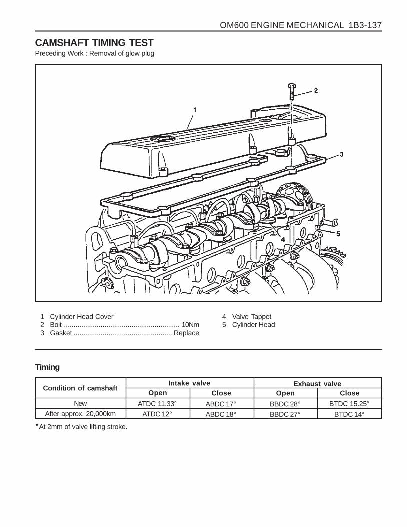
OM600 ENGINE MECHANICAL 1B3-137
CAMSHAFT TIMING TESTPreceding Work : Removal of glow plug
1 Cylinder Head Cover2 Bolt ............................................................ 10Nm3 Gasket ................................................... Replace
4 Valve Tappet5 Cylinder Head
Timing
Condition of camshaft
New
After approx. 20,000km
Intake valveOpen
ATDC 11.33°
ATDC 12°
Close
ABDC 17°
ABDC 18°
Exhaust valveOpen
BBDC 28°
BBDC 27°
Close
BTDC 15.25°
BTDC 14°�At 2mm of valve lifting stroke.

1B3-138 OM600 ENGINE MECHANICAL
6. Check the timing.
New
After approx. 20,000km
ATDC 11.33°ATDC 12°
NoticeIf timing is out standard, the camshaft should be checkedfor wear and the timing chain for stretch. If a difference ofmore than 4° exists, the timing chain should be replaced.
7. Replace the gasket and install the cylinder head cover.
Tightening Torque 10 Nm
Measurement Procedure1. Remove the cylinder head cover.
2. Rotate the engine in the direction of engine rotation untilthe intake valve of NO. 1 cylinder is completely closed. Thecam lobe faces up (arrow).
NoticeDo not rotate the engine at the bolt of the crankshaftsprocket. Do not rotate the engine in the opposite directionof engine rotation. If do, this will cause serious measuringerrors.
3. Install the dial gauge holder and dial gauge (7) with theextension (8) to the cylinder head and position the tracerpin (9) onto the valve tappet (intake valve of cylinder NO.1)with a preload of min. 3mm.
NoticeThe tracer pin should be positioned exactly vertical.
Dial gauge Holder 363 589 02 21 00Dial Gauge 001 589 53 21 00Extension 366 589 00 21 05
4. Set the dial gauge to ‘0’.
5. Rotate the engine further in direction of rotation until thedial gauge has moved back by 2mm (valve lift) to 1mm.
Tools Required001 589 53 21 00 Dial Gauge
363 589 02 21 00 Dial Gauge Holder
366 589 00 21 05 Extension

OM600 ENGINE MECHANICAL 1B3-139
CAMSHAFTPreceding Work : Removal of cylinder head cover
1 Bolt ............................................................ 25Nm2 Washer3 Camshaft Bearing Cap4 Camshaft5 Dowel Pin6 Locking Washer7 Timing Chain
8 Cylinder Head9 Oil Pan
10 Camshaft Sprocket11 Washer12 12-Sided Bolt (M11) ............. Check, 25Nm + 90°13 Gasket ................................................... Replace14 Chain Tensioner ........................................ 80Nm

1B3-140 OM600 ENGINE MECHANICAL
3. Remove the starter motor and install the engine lock.
Engine Lock 602 589 00 40 00
Tools Required602 589 00 40 00 Engine Lock
Removal Procedure1. Rotate the crankshaft and position the piston of no.1 cylinder
at TDC.
NoticeDo not rotate the crankshaft in the opposite direction ofengine rotation.
In this position, the markings of the camshaft/camshaftbearing cap (arrow) must be aligned.
2. Place alignment marks on the camshaft sprocket and timingchain.

OM600 ENGINE MECHANICAL 1B3-141
4. Remove the bolt and then remove the camshaft sprocket.
NoticeDuring removal, be careful not to drop the sprocket withchain. Remove the chain carefully and then pull out thesprocket.
5. Remove the chain tensioner.
6. Remove the camshaft bearing cap bolts according to theremoval order.
NoticeRemove the camshaft bearing cap bolts of 1(dark arrow)first and then remove the bolts of 2 (light arrow) onerevolution in stages until the counter-pressure is released.In order to avoid damaging the camshaft, it is essential toadhere to the removal order for the camshaft bearing caps.
OM 662LA
OM 661LA

1B3-142 OM600 ENGINE MECHANICAL
4. Install the camshaft bearing caps according to markings(1,2, 3 etc.).
7. Remove the camshaft bearing cap.
8. Pull off the camshaft.
NoticeBe careful not to miss front locking washer.
9. Pull out the locking washer.
NoticeCheck the condition of locking washer and replace ifnecessary.
Installation Procedure1. Insert the locking washer.
2. Check the valve tappet and ensure that tappet movessmoothly.
3. Coat the camshaft with oil and install the camshaft onto thecylinder head so that the TDC marking (arrow) is positionedupward vertically.

OM600 ENGINE MECHANICAL 1B3-143
5. Tighten the camshaft bearing cap bolts acccording toinstallation order.
6. Install the camshaft sprocket to be aligned the markings ofthe camshaft / camshaft bearing cap (arrow).
NoticeAlign the alignment marks on the timing chain and sprocket.
Tightening Torque 25 Nm
NoticeTighten the No. 1 bolts (light arrow) by one revolution instages first and then tighten the No.2 bolts (dark arrow).
OM 661LA
OM 662LA
7. Tighten the camshaft sprocket bolt.
Tightening Torque 25Nm + 90°

1B3-144 OM600 ENGINE MECHANICAL
10. Check the TDC marking of OT on the crankshaft.
8. Install the chain tensioner.
Tightening Torque 80 Nm
NoticeReplace the seal.
Before installation, by pumping in the oil approx. 10 times,fill the oil.
9. Remove the engine lock.
NoticeIf max. length ‘L’ of the 12-sided bolt exceeds 53.6mm,replace it.

OM600 ENGINE MECHANICAL 1B3-145
CHAIN TENSIONER
1 Chain Tensioner ........................................ 80Nm 2 Seal ....................................................... Replace

1B3-146 OM600 ENGINE MECHANICAL
NoticeAlways install the chain tensioner to be filled with oil.
Place the chain tensioner in engine oil up to over the collar on the hexagon head with the thrust pin facing up.Slowly push down the thrust pin as far as the stop 7~10 times with the aid of a press or a column drill
Faulty chain tensioners should be replaced completely.
3 Screw Plug4 Aluminum Gasket5 Ball6 Ball Guide7 Compression Spring8 Compression Spring9 Housing
10 Thrust Pin
11 Valve Disc12 O-Ring13 Snap Ring14 Compression Spring15 Filler
A Feed Bore from Cylinder HeadB To Oil Pan

OM600 ENGINE MECHANICAL 1B3-147
TIMING CHAINPreceding Work : Removal of glow plug
Removal of chain tensioner Removal of cooling fan Removal of cylinder head cover
1 Chain Link2 Timing Chain3 Camshaft Sprocket4 Outer Plate

1B3-148 OM600 ENGINE MECHANICAL
5. By rotating the crankshaft in the of engine rotation, pull outthe old timing chain with installing the new timing chain.
6. Remove the old timing chain and hold the ends of the newtiming chain to camshaft sprocket (3) with wire (arrow).
Tools Required000 589 58 43 00 Chain Assembling Device
Replacement Procedure1. Cover over the chain box with cleaning rag and grind off
both chain pins (arrow) at a chain link (1) of the timing chain.
2. Remove the outer plate (4) and chain link (1).
NoticeEnsure that the ends of the timing chain do not drop intothe chain box.
3. Loosen the chain tension with approx. 4 turns.
4. Connect the new timing chain (arrow) with chain link (1) tothe old timing chain (2).

OM600 ENGINE MECHANICAL 1B3-149
7. Insert the new chain link (1) to connect the chain.
8. Insert the new outer plate (4) into the fitting tool (8) andthen the outer plate will be held by a magnet.
Chain Assembling Device 000 589 58 43 00
9. Place the fitting tool (8) onto the chain link and press theouter plate on as far as the stop.
10. Switch over the die (9) of the fitting tool (8).

1B3-150 OM600 ENGINE MECHANICAL
In this position, the marking on camshaft / camshaft bearingcap (arrow) must also be aligned. If the markings are notaligned, the timing chain must be re-set and the injectionpump timing has to be set.
14. Position the no.1 cylinder at TDC.
11. Place the fitting tool (8) onto the chain link and rivet thechain pins one by one.
12. Check the riveting of chain pins and re-rivet if necessary.
13. Remove the wire.
Tightening Torque 35 - 40 Nm

OM600 ENGINE MECHANICAL 1B3-151
TENSIONING RAILPreceding Work : Removal of cylinder head
Removal of timing case cover
1 Tensioning Rail 2 Bearing Pin
NoticeThe plastic coating of the tensioning rail can not be replaced.

1B3-152 OM600 ENGINE MECHANICAL
CYLINDER HEAD GUIDE RAILPreceding Work : Removal of the cooling fan
Removal of poly V-beltRemoval of chain tensioner
1 Cylinder Head Cover2 Bolt ............................................................ 10Nm3 Gasket ................................................... Replace4 Camshaft Sprocket5 Washer6 12-Sided Bolt (M11) ............ Inspect, 25Nm + 90°7 Tensioning Lever8 Bolt ............................................................ 23Nm
9 Bearing Pin ........................... Sealing Compound10 Guide Rail11 Bearing Pin12 Guide Pulley13 Socket Bolt ................................................ 23Nm14 Closing Cover15 Spring16 Timing Chain

OM600 ENGINE MECHANICAL 1B3-153
Tools Required115 589 02 34 00 Sliding Hammer
116 589 20 33 00 Threaded Pin
Removal Procedure1. Removal the cylinder head cover.
2. Pull off the tensioning lever (7) and remove from the spring(15).
3. Pry off the closing cover (14) and remove the bolt (13) andthen remove the guide pulley (12).
4. Place alignment marks (arrow) on the timing chain (16) andcamshaft sprocket (4).
5. Remove the camshaft sprocket.
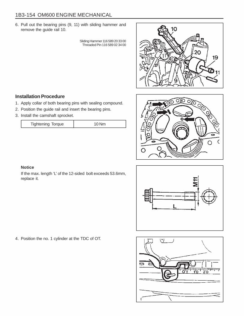
1B3-154 OM600 ENGINE MECHANICAL
4. Position the no. 1 cylinder at the TDC of OT.
6. Pull out the bearing pins (9, 11) with sliding hammer andremove the guide rail 10.
Sliding Hammer 116 589 20 33 00Threaded Pin 116 589 02 34 00
Installation Procedure1. Apply collar of both bearing pins with sealing compound.
2. Position the guide rail and insert the bearing pins.
3. Install the camshaft sprocket.
Tightening Torque 10 Nm
NoticeIf the max. length ‘L’ of the 12-sided bolt exceeds 53.6mm,replace it.
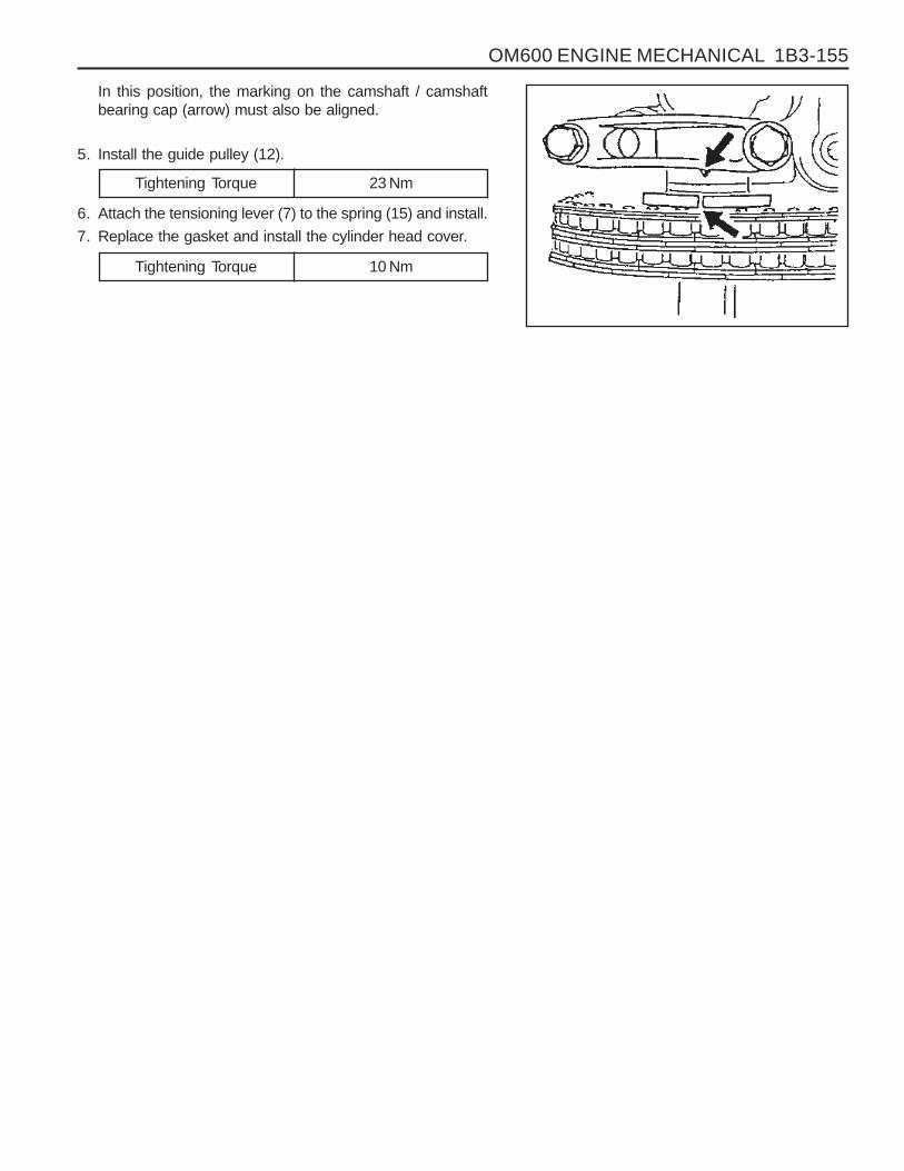
OM600 ENGINE MECHANICAL 1B3-155
In this position, the marking on the camshaft / camshaftbearing cap (arrow) must also be aligned.
5. Install the guide pulley (12).
Tightening Torque 23 Nm
6. Attach the tensioning lever (7) to the spring (15) and install.
7. Replace the gasket and install the cylinder head cover.
Tightening Torque 10 Nm

1B3-156 OM600 ENGINE MECHANICAL
TIMING CASE COVER GUIDE RAILPreceding Work : Removal of cylinder head cover
1 Bearing Pin2 Bearing Pin3 Guide Rail4 Oil Pump Chain
5 Crankshaft6 Spring7 Bushing8 Tensioning Lever

1B3-158 OM600 ENGINE MECHANICAL
CRANKSHAFT SPROCKETPreceding Work : Removal of oil pan
Removal of timing case cover
1 12-Sided Stretch Bolt (M11) .. Check, 25Nm + 90°2 Washer3 Camshaft Sprocket4 Timing Chain5 Bearing Pin6 Bearing Pin7 Oil Pump8 Oil Pump Sprocket9 Oil Pump Chain
10 Washer
11 Bolt ............................................................ 25Nm12 Crankshaft Sprocket13 Crankshaft15 Key16 Guide Rail17 Spring18 Bushing19 Tensioning Lever

OM600 ENGINE MECHANICAL 1B3-159
Special Tools116 589 07 15 00 Drift
102 589 05 33 00 Puller
Removal Procedure1. Pull out the tensioning lever (19) together with the spring
(17) and guide rail (16) far enough until the tensioning leverhas passed the oil pump chain (9) and is resting againstthe crankshaft (13).
2. Pull out tensioning lever (19), spring (17) and bushing (18)from the bearing pin (6).
3. Pull out the guide rail (16).
4. Remove the bolt(11) and then remove the washer (10), oilpump chin (9) and sprocket (8).

1B3-160 OM600 ENGINE MECHANICAL
10. Remove the crankshaft sprocket (12) by using a puller(20).
Puller 102 589 05 33 00
5. Place alignment marks (arrow) on the timing chain (4) andcrankshaft sprocket (12).
6. Remove the woodruff key(15).
7. Place alignment marks (arrow) on the timing chain (4) andcamshaft sprocket (3).
8. Remove the chain tensioner.
9. Remove the bolt (1) and then remove the washer (2) andcamshaft sprocket (3).

OM600 ENGINE MECHANICAL 1B3-161
Installation Procedure1. Put the same alignment mark on the new crankshaft
sprocket as in the old sprocket.
NoticeCheck the timing chain, camshaft sprocket, injection pumptiming sprocket, oil pump chain and oil pump sprocket forwear and replace if necessary.
2. Install the new crankshaft sprocket (12) by using a drift (21).
NoticeAlign the groove of sprocket and woodruff key (arrow)exactly.
Drift 116 589 07 15 00
3. Fit the timing chain (4) on the crankshaft sprocket (12).
NoticeAlign the alignment marks (arrow) on the chain and sprocket.
4. Install the camshaft sprocket (3).
Tightening Torque 25 Nm + 90°
NoticePay attention on the alignment marks and dowel pin (arrow).

1B3-162 OM600 ENGINE MECHANICAL
NoticeIf the max. length ‘L’ of the stretch bolt exceeds 53.6mm,replace it.
5. Fit the oil pump chain (9) on the crankshaft sprocket (12)and insert the oil pump sprocket (8) into the oil pump chainand then install it on the oil pump.
NoticeThe curved side of the oil pump sprocket should face theoil pump.
6. Insert the woodruff key (15).
7. Install the guide rail (16). Attach the spring (17) to guide railand to tensioning lever together onto the bearing pins (5,6).
NoticeEnsure that the spring is correctly located in the guide rail(arrow).

OM600 ENGINE MECHANICAL 1B3-163
PISTONPreceding Work : Removal of the cylinder head
Removal of the oil pump
1 Oil Ring2 2nd Ring3 Top Ring4 Snap Ring .............................................. Replace5 Piston Pin6 Piston7 Connecting Rod Bushing .......................... Check
8 Connecting Rod9 Connecting Rod Upper Bearing Shell
10 Connecting Rod Lower Bearing Shell11 Connecting Rod Bearing Cap12 Connecting Rod Bolt .........................35Nm + 90°13 Crankcase14 Cylinder Bore
NoticeThere are two kinds of connecting rods (for machining) and they are different in weight approx. 15g. When replacingthe connecting rod, measure its weight and ensure that a engine has the same weight of connecting rods. If not, therewould be a unbalancing of engine.

1B3-164 OM600 ENGINE MECHANICAL
Service Data
Piston clearancePiston crown protrusion in TDC position
Connecting rod bushing diameter
Max. 0.12 mm
0.735 - 0.965 mm
26.012 - 26.018 mm
Connecting Rod Bolt Dimensions
Thread
Stretch shaft(C) diameter (new)
Minimum stretch shaft diameter (C)
Length(L)(new)
Tools Required000 589 04 14 00 Tensioning Strap001 589 53 21 00 Dial Gauge
363 589 02 21 00 Dial Gauge Holder
M9 x 1
7.4-0.1 mm
7.1 mm
52-0.3 mm

OM600 ENGINE MECHANICAL 1B3-165
Removal Procedure1. Remove combustion residues from the cylinder bores.
2. Remove the connecting rod bolts (12) and then removethe connecting rod bearing caps(11).
3. Remove the connecting rod bearing shells (9, 10).
NoticeBe careful not mix the bearing caps and shells each other.
4. Remove the piston (6) and connecting rod (8).
5. Remove the snap ring (4) and pull out the piston pin (5).
6. Separate the piston and connecting rod.
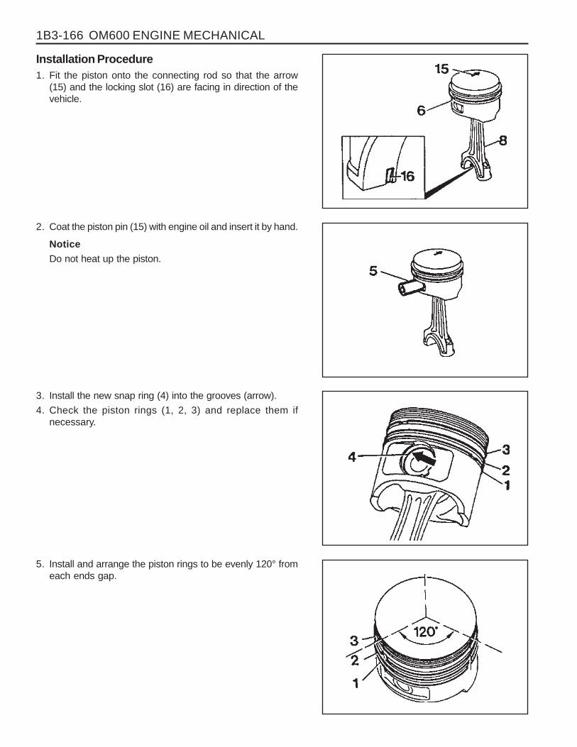
1B3-166 OM600 ENGINE MECHANICAL
Installation Procedure1. Fit the piston onto the connecting rod so that the arrow
(15) and the locking slot (16) are facing in direction of thevehicle.
2. Coat the piston pin (15) with engine oil and insert it by hand.
NoticeDo not heat up the piston.
3. Install the new snap ring (4) into the grooves (arrow).
4. Check the piston rings (1, 2, 3) and replace them ifnecessary.
5. Install and arrange the piston rings to be evenly 120° fromeach ends gap.

OM600 ENGINE MECHANICAL 1B3-167
6. Coat the cylinder bore, connecting rod bearing journal,connecting rod bearing shell and piston with oil.
7. Compress the piston rings with a tensioning strap (7).
Tensioning Strap 000 589 04 14 00
8. Insert the piston assembly into the cylinder with a woodenstick (18).
NoticeThe arrow on the piston crown must point toward the frontof vehicle.
9. Insert the connecting rod bearing shells (9, 10).
NoticeBe careful of the difference in upper and lower bearingshells and not to be changed.
10. Position the connecting rod bearings caps.
NoticePosition so that the retaining lugs are on the same side ofthe connecting rod bearing(arrow).
11. Measure stretch shaft diameter (C) of the connecting rodbolts.
Limit ‘C’ 7.1mm

1B3-168 OM600 ENGINE MECHANICAL
12. Coat the bolts (12) with oil and then tighten the bolts.
Tightening Torque 40Nm + 90°
13. Rotate the crankshaft and check axial clearance betweenthe connecting rod and crankshaft.
14. Measure clearance between the piston crown and cylinder
Standard Max. 0.12mm
15. Position the piston at TDC and measure the distancebetween the piston crown and the crankcase surface.
NoticeMeasure at points marked.
Dial Gauge 001 589 00 53 21Dial Gauge Holder 363 589 02 21 00
Standard Max. 0.965 mm

OM600 ENGINE MECHANICAL 1B3-169
OIL FILTER
1 Nut ............................................................ 25 Nm2 Oil Filter ..................................................... Cover3 O-Ring ................................................... Replace4 Oil Filter ............... Element Replace If necessary5 Oil Filter Housing
6 Bolt (M8) .................................................... 10Nm7 Oil Pressure Switch8 Gasket9 Bolt ........................................................... 25 Nm

1B3-170 OM600 ENGINE MECHANICAL
Removal & Installation Procedure1. Remove the oil filter cover and then drain the oil.
2. Remove the oil pressure switch line.
3. Remove the oil filter housing.
4. Clean the sealing surface.5. Installation should follow the removal procedure in the
reverse order.

OM600 ENGINE MECHANICAL 1B3-171
OIL PAN
1 Gasket ................................................... Replace2 Upper Oil Pan3 Combination Bolt ...................................... 10 Nm4 Combination Bolt ...................................... 10 Nm5 Gasket ................................................... Replace
6 Lower Oil Pan7 Combination Bolt ...................................... 25 Nm8 Drain Plug ................................................. 25 Nm9 Washer Seal .......................................... Replace
10 Oil Pan
*Remove and install as numerical sequence.
NoticeReplace the washer seal with new one.
OM662LA OM661LA

1B3-172 OM600 ENGINE MECHANICAL
Oil Circulation

OM600 ENGINE MECHANICAL 1B3-173
Oil Filter
a From Oil Pumpb To Main Oil Galleryc To Oil Pan

1B3-174 OM600 ENGINE MECHANICAL
OIL SPRAY NOZZLE
1 Fitting Sleeve2 Oil Spray Nozzle
Disassembly Procedure1. Remove oil pan or crankshaft.2. Loose the bolt and then remove the nozzle.
3 Combination Bolt ..................................... 10 NmA Oil Duct

OM600 ENGINE MECHANICAL 1B3-175
OIL PUMP
1 Oil Pump2 Piston3 Pressure Spring4 Guide Pin
5 Screw Plug ................................................ 50 Nm6 Combination Bolt ...................................... 25 Nm7 Oil Strainer8 Bracket
Disassembly Procedure1. Remove the oil pan.
2. Unscrew the mounting bolt of spracket.

1B3-176 OM600 ENGINE MECHANICAL
Tightening Torque 10 Nm
3. Unscrew the oil strainer bracket bolt.
4. Remove the oil pump.
5. Unscrew the screw plug and remove the relief valve.
6. Installation should follow the removal procedure in thereverse order.

OM600 ENGINE MECHANICAL 1B3-177
CYLINDER HEAD PRESSURE LEAKAGE TESTPreceding Work : Removal of the cylinder head
Removal of the exhaust manifold Removal of the valve
1 Feed Pipe2 Bolt3 Return Connection4 Gasket ................................................................ Replace5 Coolant Gallery ................................................... Sealing6 Pressure Measuring Plate .................................. Completely tight to the cylinder head7 Cylinder Head .....................................................
Immerse with pressure measuring plate into warm water of approx. 60°C and pressurize with compressedairof 2 bar.
Notice
If air bubbles are seen, replace the cylinderhead.
Tools Required
115 589 34 63 00 Pressure Measuring Plate601 589 00 25 00 Suspension Device
UNIT REPAIR

1B3-178 OM600 ENGINE MECHANICAL
Height ‘A’
(cylinder head surface - cylinder head cover surface)
Minimum height after machining
Permissible unevenness of parting surface
Permissible variation of parallelism (longitud. Direction)
Peak-to-valley height
Valve arrears ‘a’
Prechamber protrusion
Service Data
In longitudinal direction
In transverse direction
Intake valve
Exhaust valve
142.9 - 143.1mm
142.5mm
0.08mm
0.0mm
Max. 0.1mm
0.0017mm
0.1 - 0.7mm0.1 - 0.7mm
7.6 - 8.1mm
FACING CYLINDER HEAD MATING SURFACEPreceding Work : Removal of prechamber
Cylinder head pressure leakage test
1 Valve2 Cylinder Head3 PrechamberA Height of Cylinder Head
B Longitudinal DirectionC Transverse Directiona Valve Arrearsb Prechamber Protrusion

OM600 ENGINE MECHANICAL 1B3-179
Measurement Procedure1. Measure height ‘A’ .
Limit 142.5 mm
NoticeIf the height is less than 142.5mm, replace the cylinder head.
2. Insert the valve (1) and measure valve arrears ‘a’.
Valve Arrears ‘a’ 0.1 - 0.7 mm
NoticeIf out of standard, machine the valve seat.
3. Install the prechamber and measure protrusion ‘C’.
Protrusion ‘C’ 7.6 - 8.1mm
4. Assemble the engine and check the valve timing.

1B3-180 OM600 ENGINE MECHANICAL
REPLACEMENT OF CRANKCASE CORE PLUG
Left Right
Core plug ....................................................... φ 34mmOM661LA - 2EAOM662LA - 3EA
Core plug ....................................................... φ 34mmOM661LA - 2EAOM662LA - 3EA
Core plug ....................................................... φ 17mmOM661LA - 1EAOM662LA - 1EA
Core plug ....................................................... φ 34mmOM661LA - 1EAOM662LA - 1EA
Left Right

OM600 ENGINE MECHANICAL 1B3-181
Tools Required
102 589 00 15 00 Drift
102 589 12 15 00 Drift
Replacement Procedure1. Completely drain the coolant.2. Remove any parts which impede access.
(Example : transmission, injection pump)
3. Place the screwdriver to the deepdrawn edge of the coreplug and pull forward and then rotate 90°.
4. Pull out the core plug with pliers.
5. Thoroughly clean the sealing surface and apply Loctite 241.
6. Install the new core plug by using a drift.
Drift 102 589 00 15 00 (F34)Drift 102 589 12 15 00 (F17)
7. Install the removed parts and fill the coolant.
NoticeThe adhesive must be allowed to harden for about 45minutes before filling of coolant.
8. Warm up the engine and check the coolant for leaks.

1B3-182 OM600 ENGINE MECHANICAL
Service Data
Height ‘Y’
Permissible unevenness of contacting surface
Permissible roughness upper contacting surface
Permissible variation of parallelism of crankcase upper
surface to lower surface in longitudinal direction
Piston protrusion at TDC to crankcase upper surface
In longitudinal direction (B)
In transverse direction (C)
Min. 299.62 mm0.06 mm
0.06 mm
0.0006 - 0.0016 mm
0.05 mm
0.965 mm
0.735 mmMax.
Min.
FACING CRANKCASE CONTACTING SURFACE
1 Crankcase2 Crankcase Contacting Surface
Y Height (crankcase upper surface - crankcaselower surface)
B Longitudinal DirectionC Transverse DirectionH Chamfer Heightb Chamfer Angle

OM600 ENGINE MECHANICAL 1B3-183
OIL GALLERY STEEL BALLPreceding Work : Removal of cooling fan
Removal of the coolant pump housing Removal of the flywheel and driven plate
1 Steel Ball ................................................. φ15mm 2 Screw Plug ...............................Loctite 241,50Nm
NoticeThe screw plug (2) has to be installed as a repair solution if the steel ball (1) is leaking.

1B3-184 OM600 ENGINE MECHANICAL
3 Steel Ball ................................................. φ17mm4 Seal
5 Screw Plug ................................................. 50Nm
NoticeThe seal (4) and screw plug (5) have to be installed as a repair solution if the steel ball (3) is leaking.
Tools Required
601 589 08 15 00 Drift

OM600 ENGINE MECHANICAL 1B3-185
Removal & Installation Procedure1. Remove the timing case cover.
2. By inserting a round bar (6) approx. 0.7m from the back tothe front side through the oil gallery, knock out the steelballs (1,3).
NoticeBe careful not to damage the bores of the steel balls.
6 Shop-made tool
3. Thoroughly clean the bores of steel balls.
4. Place the steel ball (3) onto the drift (7) with a little greaseand position to the bore and then tap until the drift stops.
Drift 601 589 08 15 00
5. Place the steel ball (1) onto the drift (7) with a little greaseand position to the bore and then tap until the drift stops.
Drift 601 589 08 1500
6. Warm up the engine and check the oil for leaks.

1B3-186 OM600 ENGINE MECHANICAL
Installation of Screw Plug
NoticeIf steel ball leaks again, install the screw plug.
1. Remove the steel ball.
2. Tap thread into the bores of the oil gallery.
NoticeFront bore : M18 ´ 1.5, depth 10mm
Rear bore : M16 ´ 1.5, depth 14mm3. Thoroughly clean the oil gallery.
4. Tighten the front plug (5) with seal (4).
5. Apply Loctite 241 and then tighten the rear plug (2).
Tightening Torque 50 Nm
Tightening Torque 50 Nm
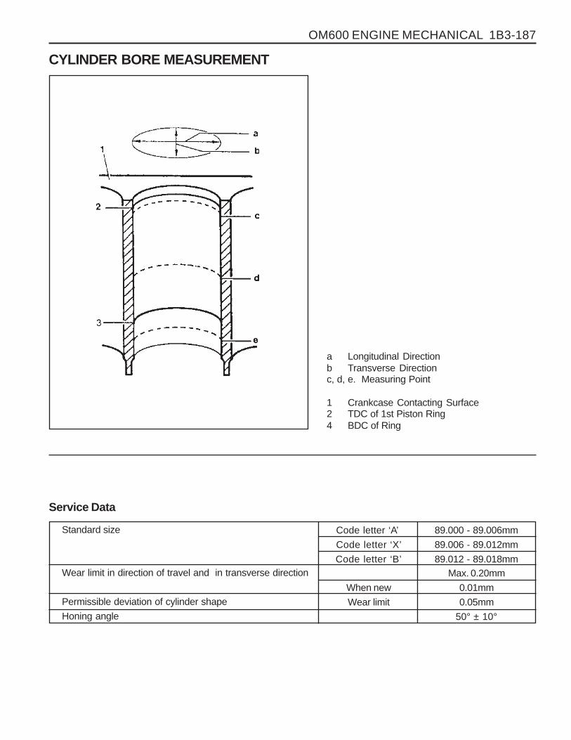
OM600 ENGINE MECHANICAL 1B3-187
Standard size
Wear limit in direction of travel and in transverse direction
Permissible deviation of cylinder shape
Honing angle
CYLINDER BORE MEASUREMENT
a Longitudinal Directionb Transverse Directionc, d, e. Measuring Point
1 Crankcase Contacting Surface2 TDC of 1st Piston Ring4 BDC of Ring
Service Data
Code letter ‘A’
Code letter ‘X’
Code letter ‘B’
When new
Wear limit
89.000 - 89.006mm
89.006 - 89.012mm
89.012 - 89.018mmMax. 0.20mm
0.01mm
0.05mm
50° ± 10°