omega security system installation instructions · platform # 05 firmware: pkg8 description: gm...
TRANSCRIPT


Platform # 05 Firmware: PKG3 Description: GM Transponder Interface: PASSKEY 3 (NO KEY REQUIRED)
Functions: Override OEM Transponder Immobilizer Via Data (NO KEY REQUIRED)
Downloadable Firmware for Platform #05: PKG3,PKG8,PKH1, PKH2,PKH3,PKH4,PKHY1,PKM2,PKN2,PKT2
See Wire Connection Guide for detailed information regarding wire functionality
Red
Green
Blue
Violet
Black
Violet/White
Pink
Pink/White
Chassis Ground
(+)12 Volt Constant
Brown Ground When Running
D2D
INPUT
INPUT
INPUT
DATA
(-)
(+)
(-)
4 PIN DATA TO DATA (D2D) CABLE (OPTIONAL ACCESSORY)
Data
P.C.USB Adaptor
USB CableOption A
Firmware UpgradesB
lue
Brow
n
CLEARCODE VIP DATA PORT
Option B - Data 2 Data Connection to RCS Data Port
Section A
Ignition Out To Coil
Igntion In To BCM
D2D
LEDProgramming button
Internet
DATA to DATA PORT (D2D): of D2D Cable plugs into the upgradeable vehicle interface module.
OPTION A: - D2D Port used to connect to USB Bootloader adaptor & computer to download & flash vehicle interface firmware.OPTION B: - D2D Port used to connect to the data port of a remote control system equipped with ClearCode Vehicle Interface Protocol.Remote control systems designed with ClearCode VIP can securely communicate via the D2D cable to transmit & receive data commands which initiate specific vehicle function such as doorlocks & immobilizer override and /or request information from the vehicle such as status of entry points (doors) or ambiant température, diesel glow plug etc… ClearCode VIP represents the doorway to vehicle integration...As an enhanced security feature, this upgradeablevehicle interface module automatically detects when the Vehicle Interface Protocol is present and deactivates the analogue override input wire (brown wire) ensuring that this module can only be activated by an authorized user.
Blue connector
Legend RCS = Remote Control System N/C = No Connection N/A = Not Applicable W2W= analogue wire to wire D2D= data 2 data
(-) /(+)
(-)Input
Data
Input
Input
I/O STATUS
WIRECOLOR
Brown
Green
Blue
Violet/White
Violet
Pink/White
Pink
Orange
Red
Black (-)
(+)
SPECIFIC WIRE CONNECTION LOCATION
Constant (+) 12 Volt Source
Chassis Ground
ConnectLocation
Vehicle
Vehicle
Vehicle
ACTIVATION and/or FUNCTIONALITY
RCS
Power Source
Ground Source
WIRE GUIDE: CONNECTIONS - 10 PIN HARNESS
Section B
Data Commands from Module to Vehicle
PIN#
1
2
3
4
5
6
7
8
9
10
Ground When Running Output of Remote Starter
D2D w2w
w2w
D2Dw2w
D2Dw2w
D2Dw2w
Connect to Blue data wire coming from PASSKEY 3harness in steering column (See Fig.1)
w2w
Input
Connect to Pink wire coming from PASSKEY 3harness in steering column
D2D = Optional use of 4 Pin Data to Data (D2D) cable will replace the analogue wire (w2w) connection
N/C
N/C
N/C
N/C
N/C N/C
N/C N/C
N/C N/C
N/C N/C
BlackViolet
Grey
Orange
Blue
Pink
PK
3
Pass-Key III
Module
B
CAR HARNESSOrange
Immobilizer Bypass Via Data
N/C N/C N/C N/C N/C
N/C N/C N/C N/C N/C
N/C N/C N/C N/C N/C N/C
N/C
N/C
“Fig. 1”
Vehicle
INPUT (+)
OUTPUT (+)
N/C N/C N/C N/C N/C N/C
Vehicle
(+)
(+)
Output
w2w
NO PROGRAMMING NEEDED
MODULE RESET: Press and hold programming button while plugging in module, LED comes ON. When LED goes OFF, release button.
Ignition Power Source Return
Connect to Pink wire coming from PASSKEY 3harness in steering column
Ignition Power Source Supply
10 P
IN
HA
RN
ES
S
+12VDC
UPGRADEABLEOVERRIDE OEMTRANSPONDER IMMOBILIZER VIA DATA

Platform # 05 Firmware: PKG8 Description: GM Import -AVEO, EPICA, WAVE Transponder Interface:
Functions: Override OEM Transponder Immobilizer Via Data (NO KEY REQUIRED)
Downloadable Firmware for Platform #05: PKG3,PKG8,PKH1, PKH2,PKH3,PKH4,PKHY1,PKM2,PKN2,PKT2
Red
Green
Blue
Violet
Black
Violet/White
Pink
Pink/White
Chassis Ground
(+)12 Volt Constant
Brown Ground When Running
D2D
INPUT
INPUT
INPUT (-)
(+)
(-)
4 PIN DATA TO DATA (D2D) CABLE (OPTIONAL ACCESSORY)
P.C.USB Adaptor
USB CableOption A
Firmware UpgradesB
lue
Brow
n
CLEARCODE VIP DATA PORT
Option B - Data 2 Data Connection to RCS Data Port
Section A
Ignition (Vehicle)
D2D
LEDProgramming button
Internet
N/C
N/C
DATA
N/C
N/C
N/C N/C
N/C N/C
INPUT
(+)OUTPUT
(+)
UPGRADEABLEOVERRIDE OEMTRANSPONDER IMMOBILIZER VIA DATA
GM IMPORT- AVEO WAVE
(-) /(+)
(-)Input
Input
Data
I/O STATUS
WIRECOLOR
Brown
Green
Blue
Violet/White
Violet
Pink/White
Pink
Orange
Red (+)
SPECIFIC WIRE CONNECTION LOCATION
Connect to Orange (Pin2) Battery wire coming from Transponder Module connector (Constant (+) 12 Volt Source)
ConnectLocation
N/C
Vehicle
Vehicle
ACTIVATION and/or FUNCTIONALITY
RCS
Power Source
Used to Bypass Passkey System Only
PIN#
1
2
3
4
5
6
7
8
9
Ground When Running Output of Remote Starter
D2D w2w
D2Dw2w
w2w
w2w
w2w
D2Dw2w
Connect in parallel to Pink wire of 10 Pin Harness
w2w
Output
Connect to Pink (Pin1) Ignition wire coming from Transponder Module connector (Module Side)
D2D = Optional use of 4 Pin Data to Data (D2D) cable will replace the analogue wire (w2w) connection
Vehicle
Connect to Black/White (Pin6) Data wire coming from Transponder Module connector
Vehicle
Once connected in parallel to Blue wire of 10 Pin Harness, connect to Pink (Pin1) ignition wire coming from Transponder Module connector (Vehicle Side)
Input
(+) Vehicle Ignition Power Source Supply
Transponder Override
Ignition Power Source Return(+)
Ignition Power Source Supply
(-)InputBlack Vehicle Ground Source10 D2Dw2w
Legend RCS = Remote Control System N/C = No Connection N/A = Not Applicable W2W= analogue wire to wire D2D= data 2 data
DATA to DATA PORT (D2D): of D2D Cable plugs into the upgradeable vehicle interface module. OPTION A: - D2D Port used to connect to USB Bootloader adaptor & computer to download & flash vehicle interface firmware.OPTION B: - D2D Port used to connect to the data port of a remote control system equipped with ClearCode Vehicle Interface Protocol.Remote control systems designed with ClearCode VIP can securely communicate via the D2D cable to transmit & receive data commands which initiate specific vehicle function such as doorlocks & immobilizer override and /or request information from the vehicle such as status of entry points (doors) or ambiant température, diesel glow plug etc… ClearCode VIP represents the doorway to vehicle integration...As an enhanced security feature, this upgradeable vehicle interface module automatically detects when the Vehicle Interface Protocol is present and deactivates the analogue override input wire(brown wire) ensuring that this module can only be activated by an authorized user.
Blue connector
WIRE GUIDE: CONNECTIONS: 10 PIN HARNESS
Section B
N/C
Data
B
Pink Ignition
BlackGround
Black/WhiteData
OrangeBattery
Transponder Module Connector Front View
N/CN/CN/C N/C N/C
Ignition (Vehicle)(+)OUTPUT
(+)
N/C N/C N/C N/C N/C N/C
Module Side
Vehicle Side
N/C N/C N/C N/C N/C N/C
Connect to Black (Pin4) Ground wire coming from Transponder Module connector
Orange
10 P
IN
HA
RN
ES
S
Ignition (Theft Deterent)
INSTALL “A” 2004-2006 CHEVROLET AVEO
2005-2006 PONTIAC WAVE
Output

Black (Ground)
Pink (Ignition)
15 PIN Connect to PIN 7
Connector
BYellow/Black
B
Gre
en/B
lack
Red (+12V) Batt
1 15
3016
Platform # 05 Firmware: PKG8 Description: GM Import -AVEO, EPICA, WAVE Transponder Interface:
Functions: Override OEM Transponder Immobilizer Via Data (NO KEY REQUIRED)
Red
Green
Blue
Violet
Black
Violet/White
Pink
Pink/White
Chassis Ground
(+)12 Volt Constant
Brown Ground When Running
D2D
INPUT
INPUT
INPUT (-)
(+)
(-)
4 PIN DATA TO DATA (D2D) CABLE (OPTIONAL ACCESSORY)
P.C.USB Adaptor
USB CableOption A
Firmware Upgrades
Blu
e
Brow
n
CLEARCODE VIP DATA PORTOption B - Data 2 Data Connection to RCS Data Port
Section C
LED
LED
Programming button
Internet
N/C
DATA
N/C
N/C
N/C N/C
INPUT
OUTPUT
UPGRADEABLEOVERRIDE OEMTRANSPONDER IMMOBILIZER VIA DATA
GM IMPORT- EPICA
(-) /(+)
(-)Input
Input
Input
Data
I/O STATUS
WIRECOLOR
Brown
Green
Blue
Violet/White
Violet
Pink/White
Pink
Orange
Red (+)
SPECIFIC WIRE CONNECTION LOCATION
Connect to Battery (Constant (+) 12 Volt Source) wire
ConnectLocation
N/C
Vehicle
Vehicle
ACTIVATION and/or FUNCTIONALITY
RCS
Power Source
Data command from Module to Vehicle
PIN#
1
2
3
4
5
6
7
8
9
Ground When Running Output of Remote Starter
D2D w2w
D2Dw2w
w2w
w2w
w2w
D2Dw2w
Connect to Pink Ignition wire PIN 11 of the 16 PIN connector
w2w
Output
Connect to Pink wire PIN 20 of the 30 PIN connector(BCM Side)
D2D = Optional use of 4 Pin Data to Data (D2D) cable will replace the analogue wire (w2w) connection
Vehicle
VehicleInput
Vehicle LED
Transponder Override
LED
Ignition Power Source Supply
(-)InputBlack Vehicle Ground Source10 D2Dw2w
Legend RCS = Remote Control System N/C = No Connection N/A = Not Applicable W2W= analogue wire to wire D2D= data 2 data
DATA to DATA PORT (D2D): of D2D Cable plugs into the upgradeable vehicle interface module. OPTION A: - D2D Port used to connect to USB Bootloader adaptor & computer to download & flash vehicle interface firmware.OPTION B: - D2D Port used to connect to the data port of a remote control system equipped with ClearCode Vehicle Interface Protocol.Remote control systems designed with ClearCode VIP can securely communicate via the D2D cable to transmit & receive data commands which initiate specific vehicle function such as doorlocks & immobilizer override and /or request information from the vehicle such as status of entry points (doors) or ambiant température, diesel glow plug etc… ClearCode VIP represents the doorway to vehicle integration...As an enhanced security feature, this upgradeable vehicle interface module automatically detects when the Vehicle Interface Protocol is present and deactivates the analogue override input wire(brown wire) ensuring that this module can only be activated by an authorized user.
Blue connector
WIRE GUIDE: CONNECTIONS: 10 PIN HARNESS
Section D
N/C
Data
N/CN/CN/C N/C N/C
Ignition (+)INPUT
(+)
N/C N/C N/C N/C N/C N/C
Connect to Black Ground wire PIN 9 of the 16 PIN connector
Orange
LED
DATA Data
D2
D
10 P
IN
HA
RN
ES
S
16 PIN Connect to PIN 9 (Ground)Connect to PIN 11 (Ignition)
Connector
30 PIN Connect to PIN 20
Connector
w2w Data Vehicle Connect to Green/Black wire PIN 7 of the 15 PIN connector (BCM Side)
Connect to Green/Black wire PIN 7 of the 15 PIN connector(Vehicle Side)
Connect to Pink wire PIN 20 of the 30 PIN connector (Vehicle Side)
Data command from Module to Vehicle
(-)
(-)
(-)
(-)
To Vehicle
To Vehicle
INSTALL “B” 2004-2006
CHEVROLET EPICA LS - LT

Platform # 05 Firmware: PKG8 Description: GM Import -AVEO, EPICA, WAVE Transponder Interface:
Functions: Override OEM Transponder Immobilizer Via Data (NO KEY REQUIRED)
1) Once the module has been properly connected, press and hold push button.
2) Turn key to IGNITION position, LED should flash 4 times.
4) Release push button, remove key to OFF position. Module is now programmed.
**To RESET, press and hold push button and plug in module. LED comes on. When LED goes off, release button.
VEHICLE PROGRAMMING:
Section E

Description: Honda/Acura Data Transponder Interface (NO KEY REQUIRED)
Functions: Override OEM Transponder Immobilizer Via Data
Downloadable Firmware for Platform #05: PKG3, PKG8, PKH1, PKH2, PKH3, PKH4, PKHY1, PKM2, PKN2, PKT2
Platform #05
Red
Orange
Green
Blue
Violet
Black
Violet/White
Pink
Pink/White
N/C
Starter Enable
Brown Ground When Running
INPUT
INPUT
N/C
INPUT
INPUT
INPUT (-)
(+)
(-)
( )+
(-)
4 PIN DATA TO DATA (D2D) CABLE (OPTIONAL ACCESSORY)
Data In (ECM Side)
See Wire Connection Guide for detailed
information regarding wire functionalityB
lue
Bro
wn
Data 2 Data Connection to RCS Data PortOption B -
Data Out (Key Side)
Programming Button
CLEARCODE VIP DATA PORT
(-) /(+)
WIRECOLOR SPECIFIC WIRE CONNECTION LOCATION
ConnectLocation ACTIVATION and/or FUNCTIONALITY
WIRE GUIDE : CONNECTIONS
Connect to Light Blue vehicle Starter Enable wire
Connect to Brown/Yellow Data wire (ECM Side)
Connect to White/Green Battery wire Constant (+) 12 Volt Source Connect to Black Chassis Ground wire
Immobilizer bypass via DataGround When Running output of remote starter.
Connect to Brown/Yellow Data wire (Key Side)
Legend RCS = Remote Control System N/C = No Connection N/A = Not Applicable W2W= analogue wire to wire D2D= data 2 data
Enables start
Blue
Green Input (-)
Brown Input (-) RCS
Violet/ White
Data Input
Violet Vehicle
Orange
Red Input (+) Vehicle
Black Input (-) Vehicle
Pink/ White
Connect to Yellow/Black Ignition wire (Key Side)
Pink
Power Source
Ground Source
Vehicle
Vehicle Data Commands from Module to Vehicle
Data Commands from Module to Vehicle
PIN#
1
2
3
4
5
6
7
8
9
10
I/O STATUS
D2D W2W
Data Output
10 PIN HARNESS D2D = Optional use of 4 Pin Data to Data (D2D) cable will replace the analogue wire (w2w) connection
D2D W2W W2W
W2W
W2W
D2D W2W
D2D W2W
INPUT
OUTPUT
(+)12 Volt Constant
Chassis Ground
Internet
USB ADAPTOR
USB CABLE
USB PORTOption A
Firmware Upgrades
Firmware: PKH1
Ignition In (ECM Side)
Ignition Out (Key Side)
HONDAIMMOBILIZER
MODULE
Starter Enable
Ground
Battery
Data
Ignition
Light Blue
Black
White/Green
Brown/Yellow
Yellow/Black BB
Connect to Yellow/Black Ignition wire (ECM Side)
N/C N/C N/C N/C N/C N/C
Ignition Power Source Return
Ignition Power Source SupplyInput
Output
(+)
(+)
W2W
W2W Vehicle
Vehicle
VEHICLE PROGRAMMING1- Once the module has been properly connected, press and hold push button, LED should turn ON.2- Turn key to IGNITION position, LED will flash3- Turn key OFF , release button, LED turns OFF. Module is now programmed.
*To RESET, unplug kit. While plugging kit back into the 10 PIN harness, press and hold programming button. LED comes on. When LED goes off, release button
Section C
DATA to DATA PORT (D2D): of D2D Cable plugs into the upgradeable vehicle interface module. OPTION A: - D2D Port used to connect to USB Bootloader adaptor & computer to download & flash vehicle interface firmware.OPTION B: - D2D Port used to connect to the data port of a remote control system equipped with ClearCode Vehicle Interface Protocol.Remote control systems designed with ClearCode VIP can securely communicate via the D2D cable to transmit & receive data commands which initiate specific vehicle function such as doorlocks & immobilizer override and /or request information from the vehicle such as status of entry points (doors) or ambiant température, diesel glow plug etc… ClearCode VIP represents the doorway to vehicle integration...As an enhanced security feature, this upgradeable vehicle interface module automatically detects when the Vehicle Interface Protocol is present and deactivates the analogue override input wire (brown wire) ensuring that this module can only be activated by an authorized user.
Blue connector
Connect to Pink wire from module Ignition Power Source SupplyInput (+)
W2W Module
OUTPUT
INPUT ( )+
( )+
D2D
10 P
IN
HA
RN
ES
S
UPGRADEABLEOVERRIDE OEMTRANSPONDER IMMOBILIZER VIA DATA

+12VDC
Platform # 05 Firmware: PKH2 Description: Honda/Acura Transponder Interface: TYPE-A (4 Wire Connector) NO KEY REQUIRED
Functions: Override OEM Transponder Immobilizer Via Data
Downloadable Firmware for Platform #05: PKG3,PKG8,PKH1, PKH2,PKH3,PKH4,PKHY1,PKM2,PKN2,PKT2
Red
Green
Blue
Violet
Black
Violet/White
Pink
Pink/White
Chassis Ground
(+)12 Volt Constant
Data (Key Side)
Brown Ground When Running
D2D
10 P
IN
HA
RN
ES
S
INPUT
INPUT
DATA INPUT
DATA OUTPUT
(-)
(+)
(-)
4 PIN DATA TO DATA (D2D) CABLE (OPTIONAL ACCESSORY)
Data (ECM Side)
See Wire Connection Guide for detailed information regarding wire functionality
P.C.
USB Adaptor
USB Cable
Option A
Firmware Upgrades
Blu
e
Brow
n
CLEARCODE VIP DATA PORT
Option B - Data 2 Data Connection to RCS Data Port
Section A
N/C
N/CN/C
Orange
LEDProgramming button
D2D
Internet
Section B
N/C
DATA to DATA PORT (D2D): of D2D Cable plugs into the upgradeable vehicle interface module.
OPTION A: - D2D Port used to connect to USB Bootloader adaptor & computer to download & flash vehicle interface firmware.OPTION B: - D2D Port used to connect to the data port of a remote control system equipped with ClearCode Vehicle Interface Protocol.Remote control systems designed with ClearCode VIP can securely communicate via the D2D cable to transmit & receive data commands which initiate specific vehicle function such as doorlocks & immobilizer override and /or request information from the vehicle such as status of entry points (doors) or ambiant température, diesel glow plug etc… ClearCode VIP represents the doorway to vehicle integration...As an enhanced security feature, this upgradeablevehicle interface module automatically detects when the Vehicle Interface Protocol is present and deactivates the analogue override input wire (brown wire) ensuring that this module can only be activated by an authorized user.
Blue connector
Legend RCS = Remote Control System N/C = No Connection N/A = Not Applicable W2W= analogue wire to wire D2D= data 2 data
(-) /(+)
(-)Input
Input
Input
DataOutput
I/O STATUS
WIRECOLOR
Brown
Green
Blue
Violet/White
Violet
Pink/White
Pink
Orange
Red
Black (-)
(+)
SPECIFIC WIRE CONNECTION LOCATION
Constant (+) 12 Volt Source
Connect to Vehicle Brown/Black ground wire
ConnectLocation
Vehicle
Vehicle
Vehicle
ACTIVATION and/or FUNCTIONALITY
RCS
Power Source
Ground Source
WIRE GUIDE: CONNECTIONS
Data Commands from Module to Vehicle
PIN#
1
2
3
4
5
6
7
8
9
10
Ground When Running Output of Remote Starter
10 PIN HARNESS
D2D w2w
D2D = Optional use of 4 Pin Data to Data (D2D) cable will replace the analogue wire (w2w) connection
D2Dw2w
w2w
D2Dw2w
D2Dw2w
N/C
N/CN/C
N/C
N/CN/C
Immobilizer Bypass Via Data
N/C
Connect to Vehicle Data wire (ECM Side)(See Vehicle Wiring Reference Chart on Page 2)
N/C
ECMSide
HONDA/ACURAIMMOBILIZER
MODULE
Synchro
Key Side
N/C N/C N/C N/C
N/C
N/C
w2w DataInput
Vehicle Connect to Vehicle Data wire (Key Side)(See Vehicle Wiring Reference Chart on Page 2)
Data Commands from Module to Vehicle
N/C N/C N/C
N/C N/C
N/C
Ground
Data
Ground
Synchro
N/CN/CN/CN/CN/C
N/C
N/CN/C
N/C
N/CN/C
Vehicle Connect to Synchro wire of vehicle(See Vehicle Wiring Reference Chart on Page 2)
w2w
N/C
INPUT
Input
UPGRADEABLEOVERRIDE OEMTRANSPONDER IMMOBILIZER VIA DATA
INPUT
Syncronizes Vehicle Data with Module
VEHICLE PROGRAMMING:Section C
1) Once module has been properly connected, turn key to IGNITION position.2) When LED flashes 4 times, module is now programmed. Turn key OFF.
*To RESET, press and hold button and plug in module. LED comes on. When LED goes off, release button.*IF LED flashes rapidly for 5 seconds, this means your ignition wiring is fine, but the GWR is not. Check this connection at the remote system.*IF LED flashes 1 time (rapidly), the ignition and GWR are fine.
BData
Synchro

DATA SYNCHRO GROUND
ACCORD1998-2002
BluePos.#3
ODYSSEY1999-2004
ACURA MDX2001-2002
ACURA CL1998-2002
ACURA TL 1998-2003
VEHICLE
Brown/BlackPos.#4
RedPos.#2
Orange/BluePos.#3
Blue/GreenPos.:#2
Brown/BlackPos.:#4
Brown/Yellow
Pos.#4
BluePos.#3
RedPos.#2
Brown/YellowPos.#4
BluePos.#3
Blue/GreenPos.#2
Brown/BlackPos.#4
PILOT
2003-2004Blue
Pos.#3
RedPos.#2
Brown/YellowPos.#4
RedPos.#2
Orange/BluePos.#3
VEHICLE WIRING REFERENCE CHARTSection D
Platform # 05 Firmware: PKH2 Description: Honda/Acura Transponder Interface: TYPE-A (4 Wire Connector) NO KEY REQUIRED
Functions: Override OEM Transponder Immobilizer Via Data
TECH NOTE: PKH2 COMPATIBILITY RULE OF THUMBPKH2 Can be used on TYPE “A” Honda/Acura Immobilizer systems. To identify this, look for the Green 5 PIN w/4 wire connectorIf you see 4 wires coming from the Green plug, the PKH2 is the right Transponder Bypasskit to use.
Section E
ACURA INTEGRA2000-2001
BluePos.#3
RedPos.:#2
Brown/BlackPos.:#4

Platform # 05 Firmware: PKH3 Description: Honda/Acura Transponder Interface: TYPE “C” (7 Wire Connector)
Functions: Override OEM Transponder Immobilizer Via Data (NO KEY REQUIRED)
Downloadable Firmware for Platform #05: PKG3,PKG8,PKH1, PKH2,PKH3,PKH4,PKHY1,PKM2,PKN2,PKT2
Red
Green
Blue
Violet
Black
Violet/White
Pink
Pink/White
Chassis Ground
Brown Ground When Running
D2D
10 P
IN
HA
RN
ES
S
INPUT
INPUT
INPUT (-)
(+)
(-)
SEE WIRE CONNECTION GUIDE FOR DETAILED INFORMATION REGARDING WIRE FUNCTIONALITYSection A
N/CN/CN/C Orange
LED
Programming button
Section B
N/C
DATA to DATA PORT (D2D): of D2D Cable plugs into the upgradeable vehicle interface module.
OPTION A: - D2D Port used to connect to USB Bootloader adaptor & computer to download & flash vehicle interface firmware.OPTION B: - D2D Port used to connect to the data port of a remote control system equipped with ClearCode Vehicle Interface Protocol.Remote control systems designed with ClearCode VIP can securely communicate via the D2D cable to transmit & receive data commands which initiate specific vehicle function such as doorlocks & immobilizer override and /or request information from the vehicle such as status of entry points (doors) or ambiant température, diesel glow plug etc… ClearCode VIP represents the doorway to vehicle integration...As an enhanced security feature, this upgradeablevehicle interface module automatically detects when the Vehicle Interface Protocol is present and deactivates the analogue override input wire (brown wire) ensuring that this module can only be activated by an authorized user.
Blue connector
Legend RCS = Remote Control System N/C = No Connection N/A = Not Applicable W2W= analogue wire to wire D2D= data 2 data
(-) /(+)
(-)Input
Input
Input
Data
I/O STATUS
WIRECOLOR
Brown
Green
Blue
Violet/White
Violet
Pink/White
Pink
Orange
Red
Black (-)
(+)
SPECIFIC WIRE CONNECTION LOCATION
Constant (+) 12 Volt Source
Chassis Ground
ConnectLocation
Vehicle
Vehicle
Vehicle
ACTIVATION and/or FUNCTIONALITY
RCS
Power Source
Ground Source
WIRE GUIDE: CONNECTIONS
Data Commands from Module to Vehicle
PIN#
1
2
3
4
5
6
7
8
9
10
Ground When Running Output of Remote Starter
10 PIN HARNESS
D2D w2w
D2D = Optional use of 4 Pin Data to Data (D2D) cable will replace the analogue wire (w2w) connection
D2Dw2w
w2w
D2Dw2w
D2Dw2w
N/CN/CN/CN/CN/CN/C
Immobilizer Bypass Via Data
N/C N/C
N/C N/C N/C N/C N/C N/C
ECM Side
1 65432 7
BHO
NDA
(+)
(+) Ignition ECM Side (See Wire Guide)OUTPUT
Ignition ECM Side (See Wire Guide)OUTPUT (+)
N/C N/C N/C
DATA Data (See Wire Guide)
Ignition Key Side (See Wire Guide)
N/C N/C N/C N/C N/C N/C
Output (+) Vehicle Connect in parallel to Pink wire of 10 PIN Harness Ignition Power Source Supplyw2w
w2w Output (+) Vehicle Ignition Power Source Supply
Connect to vehicle Data wire PIN 2 See Vehicle Wiring Reference Chart for wire colors
(+) Vehiclew2w Connect to vehicle ignition wire (Key Side) PIN 6 (See Vehicle Wiring Reference Chart for wire colors)
Once connected in parallel to Blue wire of 10 PIN harness,connect to vehicle ignition wire (ECM Side) PIN 6 (See Vehicle Wiring Reference Chart for wire colors)
Ignition Power Source ReturnInput
INPUT
UPGRADEABLEOVERRIDE OEMTRANSPONDER IMMOBILIZER VIA DATA
TECH NOTE: PIN 6TEST WIRE BEFORE CUTTINGVerify PIN6 is the ignition sourceof the vehicle transponder system
+12VDC
(+)12 Volt Constant
WIRE SIDE OFCONNECTOR
Internet
4 PIN DATA TO DATA (D2D) CABLE (OPTIONAL ACCESSORY)USB ADAPTOR
USB CABLE
USB PORTOption A
Firmware UpgradesB
lue
Brow
n Option B - Data 2 Data Connection to RCS Data Port
Key Side

DATA IGNITION GROUND
Acura EL 1.72005 - 01
Brown/ YellowPos.#1
Acura MDX2006 - 2003
Acura RSX2006 - 2002
VEHICLE
Red/BluePos.#2
Yellow/Pos.#6
Black
Red/BluePos.#2
RedPos.#2
Green/WhitePos.#6
Yellow/BlackPos.#6
Brown/ YellowPos.#1
Brown/ YellowPos.#1
Acura TSX2007 - 2003
Red/BluePos.#2
Yellow/Pos.#6
Black Brown/ YellowPos.#1
Honda CRV2006 - 03
Honda Accord2007 - 2003
Brown/ YellowPos.#1
Brown/ YellowPos.#1
Red/BluePos.#2
WhitePos.#2
Yellow/BlackPos.#6
Yellow/BlackPos.#6
Red/BluePos.#2
Yellow/Pos.#6
Black Brown/ YellowPos.#1
Honda Element2007 - 2003
Brown/ YellowPos.#1
WhitePos.#2
Yellow/BlackPos.#6
Honda Civic2005 - 2001
Acura TL2007 - 2004
Brown/ YellowPos.#1
Red/BluePos.#2
Blue/Pos.#6
Black
Honda Pilot2007 - 2005
Brown/ YellowPos.#1
Red/GreenPos.#2
Red/WhitePos.#6
Honda Odyssey2007 - 2005
BlackPos.#1
Red/BluePos.#2
Yellow/BlackPos.#6
Honda Ridgeline2007-2006
Red/BluePos.#2
Green/BlackPos.#6
Brown/ YellowPos.#1
Platform # 05 Firmware: PKH3 Description: Honda/Acura Transponder Interface: TYPE “C” (7 Wire Connector)
Functions: Override OEM Transponder Immobilizer Via Data (NO KEY REQUIRED)
VEHICLE PROGRAMMING
Section C
1) Once module has been properly connected, press and hold programming button.
2) Turn the ignition key to ON position, LED should blink.
3) Release programming button, module is now programmed.
*To RESET, press and hold button and plug in module. LED comes on. When LED goes off, release button.
VEHICLE WIRING REFERENCE CHART
Section D
Honda Fit2007
Light Green/BlackPos.#2
Yellow/BlackPos.#6
Brown/ YellowPos.#1
INSTALLATION NOTES:
Honda Accord: Connector in vehicle is WHITE.

+12VDC
Platform # 05 Firmware: PKH4 Description: Honda/Acura Transponder Interface: TYPE “C” (7 Wire Connector)
Functions: Override OEM Transponder Immobilizer Via Data (NO KEY REQUIRED)
Downloadable Firmware for Platform #05: PKG3,PKG8,PKH1, PKH2,PKH3,PKH4,PKHY1,PKM2,PKN2,PKT2
Red
Green
Blue
Violet
Black
Violet/White
Pink
Pink/White
Chassis Ground
(+)12 Volt Constant
Brown Ground When Running
D2D
INPUT
INPUT
INPUT
DATA
(-)
(+)
(-)
4 PIN DATA TO DATA (D2D) CABLE (OPTIONAL ACCESSORY)
Data (ECM Side)
See Wire Connection Guide for detailed information regarding wire functionality
P.C.
USB Adaptor
USB Cable
Option A
Firmware UpgradesB
lue
Brow
n
CLEARCODE VIP DATA PORT
Option B - Data 2 Data Connection to RCS Data Port
Section A
N/CN/CN/C Orange
LEDProgramming button
D2D
Internet
Section B
N/C
DATA to DATA PORT (D2D): of D2D Cable plugs into the upgradeable vehicle interface module.
OPTION A: - D2D Port used to connect to USB Bootloader adaptor & computer to download & flash vehicle interface firmware.OPTION B: - D2D Port used to connect to the data port of a remote control system equipped with ClearCode Vehicle Interface Protocol.Remote control systems designed with ClearCode VIP can securely communicate via the D2D cable to transmit & receive data commands which initiate specific vehicle function such as doorlocks & immobilizer override and /or request information from the vehicle such as status of entry points (doors) or ambiant température, diesel glow plug etc… ClearCode VIP represents the doorway to vehicle integration...As an enhanced security feature, this upgradeablevehicle interface module automatically detects when the Vehicle Interface Protocol is present and deactivates the analogue override input wire (brown wire) ensuring that this module can only be activated by an authorized user.
Blue connector
Legend RCS = Remote Control System N/C = No Connection N/A = Not Applicable W2W= analogue wire to wire D2D= data 2 data
(-) /(+)
(-)Input
Input
Input
Data
I/O STATUS
WIRECOLOR
Brown
Green
Blue
Violet/White
Violet
Pink/White
Pink
Orange
Red
Black (-)
(+)
SPECIFIC WIRE CONNECTION LOCATION
Constant (+) 12 Volt Source
Chassis Ground
ConnectLocation
Vehicle
Vehicle
Vehicle
ACTIVATION and/or FUNCTIONALITY
RCS
Power Source
Ground Source
WIRE GUIDE: CONNECTIONS
Data Commands from Module to Vehicle
PIN#
1
2
3
4
5
6
7
8
9
10
Ground When Running Output of Remote Starter
10 PIN HARNESS
D2D w2w
D2D = Optional use of 4 Pin Data to Data (D2D) cable will replace the analogue wire (w2w) connection
D2Dw2w
w2w
D2Dw2w
D2Dw2w
N/CN/CN/CN/CN/CN/C
Immobilizer Bypass Via Data
N/C N/C
N/C N/C N/C N/C N/C N/C
VEHICLE PROGRAMMING Section C
1) Once module has been properly connected, turn key to IGNITION position, LED goes on.
2) After LED turns OFF, module is now programmed.
*To RESET, press and hold button and plug in module. LED comes on. When LED goes off, release button.
N/C
N/CN/C
N/C
N/C
N/C
N/C
N/C
N/C
ECM Side
1 65432 7
N/CN/CN/CN/CN/CN/C
Connect to Light Green Data Wire PIN 3 of the White 7 PIN connector located on key cylinder.
N/C N/C N/C
N/C N/C N/C
N/C
N/C
N/C
N/C
N/C
N/C
HOND
A
Key Side
UPGRADEABLEOVERRIDE OEMTRANSPONDER IMMOBILIZER VIA DATA
2006 HONDA CIVIC and ACURA CSX
N/CN/CN/C N/CN/CN/C
N/C
N/C N/C
10 P
IN
HA
RN
ES
S
Light Green Data Wire

+12VDC
Platform # 05 Firmware: PKHY1 Description: Hyundai/KIA Transponder Interface: Tiburon/Sorento (NO KEY REQUIRED)
Functions: Data Transponder Interface: Override OEM Transponder Immobilizer Via Data Downloadable Firmware for Platform #05: PKG3,PKG8,PKH1, PKH2,PKH3,PKH4,PKHY1,PKM2,PKN2,PKT2
Red
Green
Blue
Violet
Black
Violet/White
Pink
Pink/White
Chassis Ground
(+)12 Volt Constant
Brown Ground When Running
D2D
10 P
IN
HA
RN
ES
S
INPUT
INPUT
INPUT
DATA
(-)
(+)
(-)
4 PIN DATA TO DATA (D2D) CABLE (OPTIONAL ACCESSORY)
Data (See Wire Guide)
See Wire Connection Guide for detailed information regarding wire functionality
P.C.
USB Adaptor
USB CableOption A
Firmware Upgrades
Blu
e
Brow
n
CLEARCODE VIP DATA PORT
Option B - Data 2 Data Connection to RCS Data Port
Section A
N/CN/CN/C
Security LED Immobilizer Side
Orange
LEDProgramming button
D2D
Internet
Section B
OUTPUT
N/C
DATA to DATA PORT (D2D): of D2D Cable plugs into the upgradeable vehicle interface module.
OPTION A: - D2D Port used to connect to USB Bootloader adaptor & computer to download & flash vehicle interface firmware.OPTION B: - D2D Port used to connect to the data port of a remote control system equipped with ClearCode Vehicle Interface Protocol.Remote control systems designed with ClearCode VIP can securely communicate via the D2D cable to transmit & receive data commands which initiate specific vehicle function such as doorlocks & immobilizer override and /or request information from the vehicle such as status of entry points (doors) or ambiant température, diesel glow plug etc… ClearCode VIP represents the doorway to vehicle integration...As an enhanced security feature, this upgradeablevehicle interface module automatically detects when the Vehicle Interface Protocol is present and deactivates the analogue override input wire (brown wire) ensuring that this module can only be activated by an authorized user.
Blue connector
Legend RCS = Remote Control System N/C = No Connection N/A = Not Applicable W2W= analogue wire to wire D2D= data 2 data
(-) /(+)
(-)Input
Input
Input
Data
I/O STATUS
WIRECOLOR
Brown
Green
Blue
Violet/White
Violet
Pink/White
Pink
Orange
Red
Black (-)
(+)
SPECIFIC WIRE CONNECTION LOCATION
Constant (+) 12 Volt Source
Chassis Ground
ConnectLocation
Vehicle
Vehicle
Vehicle
ACTIVATION and/or FUNCTIONALITY
RCS
Power Source
Ground Source
WIRE GUIDE: CONNECTIONS
Data Commands from Module to Vehicle
PIN#
1
2
3
4
5
6
7
8
9
10
Ground When Running Output of Remote Starter
10 PIN HARNESS
D2D w2w
D2D = Optional use of 4 Pin Data to Data (D2D) cable will replace the analogue wire (w2w) connection
D2Dw2w
w2w
w2w
w2w
D2Dw2w
D2Dw2w
w2w
Input
N/CN/CN/CN/CN/CN/C
Vehicle
Vehicle
Output
Immobilizer Bypass Via Data
Connect to vehicle ignition wire(See Vehicle Connector Guide)
Ignition In
INPUT
Input
Vehicle
N/C
Connect to Vehicle Data wire(See Vehicle Connector Guide)
Ignition Power Source Supply
N/C
N/C N/C N/C N/C N/C N/C
INPUT
N/C N/C N/C
N/C N/C N/C N/C N/C N/C
Security LED Cluster Side
Connect to vehicle Security LED wire, cluster side(Vehicles equipped with a Passkey LED indicator, use Pink/White & Pink wires as indicated in Tech Notes on Page 2)
Connect to vehicle Security LED wire, immobilizer side (Vehicles equipped with a Passkey LED indicator, use Pink/White & Pink wires as indicated in Tech Notes on Page 2)
(-)
(-)
(-)
(-)
Prevents security LED to come on during remote start
Prevents security LED to come on during remote start
(+)
(+)
UPGRADEABLEOVERRIDE OEMTRANSPONDER IMMOBILIZER VIA DATA
VEHICLE PROGRAMMING Section C
1) Once module has been properly connected, press and hold programming button while turning the key to IGNITION position - LED should come on solid.
2) Start vehicle by key: LED will begin to flash. Release button and turn key off. Module is now programmed.
*TO RESET: PRESS AND HOLD BUTTON AND PLUG IN MODULE. LED COMES ON. WHEN LED GOES OFF, RELEASE BUTTON.

Platform # 05 Firmware: PKHY1 Description: Hyundai/KIA Transponder Interface: Tiburon/Sorento (NO KEY REQUIRED)
Functions: Data Transponder Interface: Override OEM Transponder Immobilizer Via Data Section D
VEHICLE CONNECTOR GUIDE
Section E
TECH NOTES
2002-03 XG300, XG350: - Green wire: To security lamp (Brown/White cluster side), Blue wire: To security lamp (Brown/White side)
2004 - 2005 XG350:- Green wire: To security lamp (Pink cluster side), Blue wire: To security lamp (Pink side)
2005 (V6) Sedona, Sorento, Sportage:- Pink/White wire: To security lamp wire cluster side, Pink wire: To security lamp wire immobiliser side
2005(V6) Tiburon and Sportage- Pink/White wire: not used, Pink wire: not used
immobilizer
immobilizer
Xg300, Xg350 White connector under dash driver’s side, nextto diagnostic connector: Pin 8 - connect to green wire.
Hyundai Tiburon
Violet from PKHY1
Blue/Orange (Data)
1 10
11 20
“Fig. B”
Connector located left of steering column.
Tiburon Connector I, behind fuse box: Pin 20 - connect toblue/orange wire. NOTE: -Green wire: not usedand Blue wire: not used.
Sedona
Orange
Red Wire
Violet
BPink/White
Pink
“Fig. C”
Immobilizer SideWire Side
Connector located right of steering column.
Sedona Connector can be found on immobilizer unit:right side of steering column.
Sorento
Blue/Orange
Blue
VioletPink/White
Pink
“Fig. D”
Wire Side Immobilizer Side
B
Connector located under dash on driver side, to the right of steering column.
Sorento (See Fig. D)Location of immobilizer unit: under dash, driver side: right side of steering column.
*12
458 7 6
Kia Sportage 2005/2006 V6 2.7L ONLY
Violet f rom PKHY1
Brown/Orange (Data)
“Fig. E”
Connector located right of steering column.
KIA Sportage Location of immobilizer unit: under dash, driver side: right side of steering column.
BBrown/White wire, Pink for 2004
Cluster Side
Immobilizer Side
White connector located behind switch panel left side of dash.
Pink/White
Pink
“Fig. A” XG300, XG350

Platform # 05 Firmware: PKM2 Description: Mazda Transponder Interface: MPV/Miata (PKM2) NO KEY REQUIRED
Functions: Data Transponder Interface: Override OEM Transponder Immobilizer Via Data
Downloadable Firmware for Platform #05: PKG3,PKG8,PKH1, PKH2,PKH3,PKH4,PKHY1,PKM2,PKN2,PKT2
Red
Green
Blue
Violet
Black
Violet/White
Pink
Pink/White
Brown Ground When Running
D2D
INPUT
INPUT
INPUT
DATA
(-)
(+)
(-)
4 PIN DATA TO DATA (D2D) CABLE (OPTIONAL ACCESSORY)
Data (ECM Side)
See Wire Connection Guide for detailed information regarding wire functionality
P.C.
USB Adaptor
USB Cable
Option A
Firmware Upgrades
Blu
e
Brow
n
CLEARCODE VIP DATA PORT
Option B - Data 2 Data Connection to RCS Data Port
Section A
N/CN/CN/C
Ignition (ECM Side)
Orange
Chassis Ground
(+)12 Volt Constant
LEDProgramming button
D2D
Internet
Section B
OUTPUT (+)
(+)
N/C
DATA to DATA PORT (D2D): of D2D Cable plugs into the upgradeable vehicle interface module.
OPTION A: - D2D Port used to connect to USB Bootloader adaptor & computer to download & flash vehicle interface firmware.OPTION B: - D2D Port used to connect to the data port of a remote control system equipped with ClearCode Vehicle Interface Protocol.Remote control systems designed with ClearCode VIP can securely communicate via the D2D cable to transmit & receive data commands which initiate specific vehicle function such as doorlocks & immobilizer override and /or request information from the vehicle such as status of entry points (doors) or ambiant température, diesel glow plug etc… ClearCode VIP represents the doorway to vehicle integration...As an enhanced security feature, this upgradeablevehicle interface module automatically detects when the Vehicle Interface Protocol is present and deactivates the analogue override input wire (brown wire) ensuring that this module can only be activated by an authorized user.
Blue connector
Legend RCS = Remote Control System N/C = No Connection N/A = Not Applicable W2W= analogue wire to wire D2D= data 2 data
(-) /(+)
(-)Input
Input
Input
Data
I/O STATUS
WIRECOLOR
Brown
Green
Blue
Violet/White
Violet
Pink/White
Pink
Orange
Red
Black (-)
(+)
SPECIFIC WIRE CONNECTION LOCATION
Constant (+) 12 Volt Source
Connect to Black or Black/Orange Vehicle Ground wire
ConnectLocation
Vehicle
Vehicle
Vehicle
ACTIVATION and/or FUNCTIONALITY
RCS
Power Source
Ground Source
WIRE GUIDE: CONNECTIONS
Data Commands from Module to Vehicle
PIN#
1
2
3
4
5
6
7
8
9
10
Ground When Running Output of Remote Starter
10 PIN HARNESS
D2D w2w
D2D = Optional use of 4 Pin Data to Data (D2D) cable will replace the analogue wire (w2w) connection
D2Dw2w
w2w
w2w
w2w
D2Dw2w
D2Dw2w
w2w
Output
N/CN/CN/CN/CN/CN/C
Vehicle
Vehicle(+)
(+)
Output
Immobilizer Bypass Via Data
Connect in parallel to Pink wire of 10 PIN Harness
Ignition ECM Side
INPUT
OUTPUT (+)
(+)
Input
Vehicle
N/C
Connect to Blue/Black Vehicle Data wire (ECM Side)*Data wire in the Miata is Red/Black
Connect to Black/White Vehicle Ignition wire (Key Side)
Once connected in parallel to Blue wire of 10 PIN harness, connect to Black/White Vehicle Ignition wire (ECM Side)
Ignition Power Source Supply
Ignition Power Source Supply
Ignition Power Source Return
N/C
DATA
ECMSide
MAZDAIMMOBILIZER
MODULE
Black/White
Blue/Black
Black or Black/Orange
Ignition
Data
Ground
Immobilizer module is located under dash on the driver side to the right of the steering column.
Key Side
N/C N/C N/C N/C N/C N/C
w2w Data Vehicle Connect to Blue/Black Vehicle Data wire (Key Side)*Data wire in the Miata is Red/Black
Data Commands from Module to Vehicle
VEHICLE PROGRAMMING Section C
1) Once module has been properly connected, press and hold programming button while turning the key to IGNITION position - LED should come on solid.
2) Start vehicle by key: LED will begin to flash. Release button and turn key off. Module is now programmed.
*TO RESET: PRESS AND HOLD BUTTON AND PLUG IN MODULE. LED COMES ON. WHEN LED GOES OFF, RELEASE BUTTON.
UPGRADEABLEOVERRIDE OEMTRANSPONDER IMMOBILIZER VIA DATA
Data (Key Side)
Ignition (Key Side)
BB
+12VDC
10 P
IN
HA
RN
ES
S
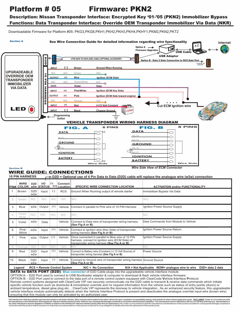
Platform # 05 Firmware: PKN2 Description: Nissan Transponder Interface: Encrypted Key ‘01-’05 (PKN2) Immobilizer Bypass
Functions: Data Transponder Interface: Override OEM Transponder Immobilizer Via Data (NKR)
Downloadable Firmware for Platform #05: PKG3,PKG8,PKH1,PKH2,PKH3,PKH4,PKHY1,PKM2,PKN2,PKT2
Red
Green
Blue
Violet
Black
Violet/White
Pink
Pink/White
Chassis Ground
(+)12 Volt Constant
N/C
Brown Ground When Running
D2D
INPUT
INPUT
INPUT
DATA
(-)
(+)
(-)
4 PIN DATA TO DATA (D2D) CABLE (OPTIONAL ACCESSORY)
Data
See Wire Connection Guide for detailed information regarding wire functionality
P.C.
USB Adaptor
USB Cable
Option A
Firmware Upgrades
Blu
e
Brow
n
CLEARCODE VIP DATA PORT
Option B - Data 2 Data Connection to RCS Data Port
Section A
N/CN/C
N/CN/CN/C
Ignition (ECM Key Side)
Ignition (ECM Side toward engine)
Orange
DATA
N/C
N/C
N/C
N/C
GROUND
IGNITION
BATTERY
8 PINS
DATA
GROUND
IGNITION
BATTERY
N/C
6 PINS
Wire SideWire Side
FIG. A FIG. B
VEHICLE TRANSPONDER WIRING HARNESS DIAGRAM
LEDProgramming button
D2D
Internet
Section B
OUTPUT (+)
(+)
DATA to DATA PORT (D2D): of D2D Cable plugs into the upgradeable vehicle interface module.
OPTION A: - D2D Port used to connect to USB Bootloader adaptor & computer to download & flash vehicle interface firmware.OPTION B: - D2D Port used to connect to the data port of a remote control system equipped with ClearCode Vehicle Interface Protocol.Remote control systems designed with ClearCode VIP can securely communicate via the D2D cable to transmit & receive data commands which initiate specific vehicle function such as doorlocks & immobilizer override and /or request information from the vehicle such as status of entry points (doors) or ambiant température, diesel glow plug etc… ClearCode VIP represents the doorway to vehicle integration...As an enhanced security feature, this upgradeablevehicle interface module automatically detects when the Vehicle Interface Protocol is present and deactivates the analogue override input wire (brown wire) ensuring that this module can only be activated by an authorized user.
Blue connector
Legend RCS = Remote Control System N/C = No Connection N/A = Not Applicable W2W= analogue wire to wire D2D= data 2 data
(-) /(+)
(-)Input
Input
Input
Data
I/O STATUS
WIRECOLOR
Brown
Green
Blue
Violet/White
Violet
Pink/White
Pink
Orange
Red
Black (-)
(+)
SPECIFIC WIRE CONNECTION LOCATION
Connect to Battery wire (Constant (+) 12 Volt Source) oftransponder wiring harness (See Fig A or B)
Connect to Ground wire of transponder wiring harness(See Fig A or B)
ConnectLocation
Vehicle
Vehicle
Vehicle
ACTIVATION and/or FUNCTIONALITY
RCS
Power Source
Ground Source
WIRE GUIDE: CONNECTIONS
Data Commands from Module to Vehicle
PIN#
1
2
3
4
5
6
7
8
9
10
Ground When Running output of remote starter
10 PIN HARNESS
D2D w2w
D2Dw2w
w2w
w2w
w2w
D2Dw2w
D2Dw2w
w2w
Output
N/C N/C N/C N/C N/C N/C
N/CN/CN/CN/CN/CN/C
Vehicle
Vehicle(+)
(+)
Output
Immobilizer Bypass Via Data
Connect in parallel to Pink wire of 10 PIN Harness
This Interface kit / Data Bus Interface part has been tested on the listed vehicles. Other vehicles will be added to the select vehicle list upon completion of compatibility testing. Visit website for latest vehicle application guide. DISCLAIMER: Under no circumstances shall the manufacturer or the distributors of the bypass kit / data bus interface part(s) be held liable for any consequential damages sustained in connection with the part(s) installation. The manufacturer and it’s distributors will not, nor will they authorize any representative or any other individual to assume obligation or liability in relation to the interface kit / data bus interface part(s) other than its replacement. N.B.:Under no circumstances shall the manufacturer and distributors of this product are liable for consequential damages sustained in connection with this product neither assumes nor authorizes any representative or other person to assume for it any obligation or liability other than the replacement of this product only.
Ignition (ECM Side)
INPUT
OUTPUT (+)
(+)
Input
Vehicle
Connect to Data wire of transponder wiring harness(See Fig A or B)
Connect to Ignition wire (Key Side) of transponder wiring harness (See Fig A or B)
Once connected in parallel to Blue wire of 10 PIN harness, connect to Ignition wire (ECM Side) of transponder wiring harness (See Fig A or B)
Ignition Power Source Supply
Ignition Power Source Supply
Ignition Power Source Return
D2D = Optional use of 4 Pin Data to Data (D2D) cable will replace the analogue wire (w2w) connection
UPGRADEABLEOVERRIDE OEMTRANSPONDER IMMOBILIZER VIA DATA
+12VDC
10 P
IN
HA
RN
ES
S
N/CN/CN/C
N/C N/C N/C N/C N/C N/C
N/C
Cut ECM Ignition wire
B
Wire Side View of ECM Connector
B

Platform # 05 Firmware: PKN2 Description: Nissan Transponder Interface: Encrypted Key ‘01-’05 (PKN2) Immobilizer Bypass
Functions: Data Transponder Interface: Override OEM Transponder Immobilizer Via Data (NKR)
VEHICLES 2004 2003 2002
ALTIMA
MAXIMA
PATHFINDER
*
* *
*
N/A
**
2001
*
*
*
SENTRA
N/AN/A
N/A
2005
*
N/A
N/A
N/A
N/AX-TRAIL
* * * * *
VEHICLE COMPATIBILITY CHART
VEHICLE PROGRAMMING - 1 Valid Key Required
Section D
Section C
1) Once all wires have been properly connected, plug in the module. The module LED should come ON.
2) Turn Ignition key to IGNITION ON position, LED will flash during the programming process. (It could take up to 2 minutes to program) LED will turn ON for 1 second then turn OFF to indicate when programming is complete. Remove Ignition key. Module is now programmed and ready for use.
TO RESET MODULE: Press and hold button while plugging in the module, LED will flash rapidly. When LED turns OFF, release button.
*IF the module has already been programmed, LED will turn OFF immediately after you plug in module.
2006
*
N/A
N/A
N/A
N/A * *

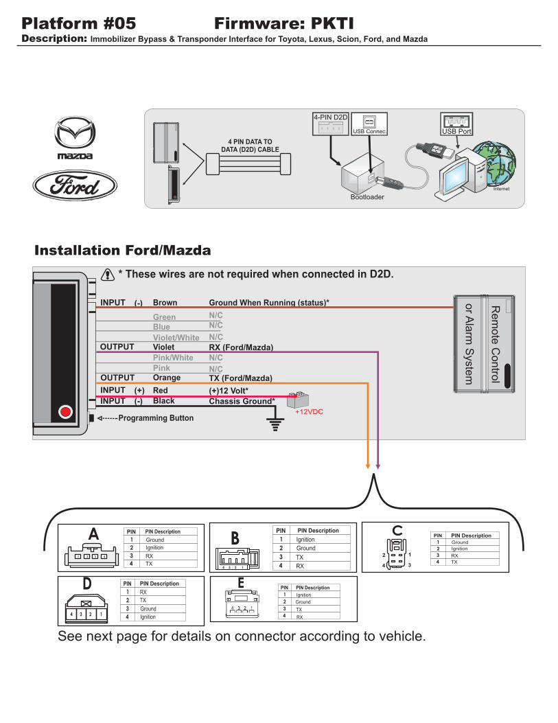
Description: Toyota/Lexus Immobilizer Bypass & Transponder Interface (NO KEY REQUIRED)
Functions: Data Bus Interface: Override OEM Transponder Immobilizer Via Data
Downloadable Firmware for Platform #05: PKG3, PKG8, PKH1, PKH2, PKH3, PKH4, PKHY1, PKM2, PKN2, PKT2
Platform #05 Firmware: PKT2
Red
Orange
Green Blue
Violet
Black
Violet/White
Pink
Pink/White
Data IMO
N/C
N/C
Ignition In (Vehicle)
Security Light (Vehicle)
Brown Ground When Running
D2D
INPUT
INPUT
INPUT
INPUT
INPUT
INPUT (-)
(+)
(-)
( )+
(-)
4 PIN DATA TO DATA (D2D) CABLE (OPTIONAL ACCESSORY)
Data IMI
See Wire Connection Guide for detailed
information regarding wire functionalityB
lue
Bro
wn
Data 2 Data Connection to RCS Data PortOption B -
Data IMI
?Programming Button
CLEARCODE VIP DATA PORT
DA
TA
IM
O
(-) /(+)
WIRECOLOR SPECIFIC WIRE CONNECTION LOCATION
ConnectLocation ACTIVATION and/or FUNCTIONALITY
WIRE GUIDE : CONNECTIONS
Connect to vehicle Security LED wire. *To turn LED off, connect Green wire from module to corresponding Security Light Wire. *See Vehicle Wiring Reference Chart
Ignition
Connect to ECM side of IMI wire*See Vehicle Wiring Reference Chart
Connect in parallel with IMO wire*See Vehicle Wiring Reference Chart Constant (+) 12 Volt Source Chassis Ground
Activate Immobilizer overrideGround When Running output of remote starter.
Connect to vehicle side of IMI wire.*See Vehicle Wiring Reference Chart
Legend RCS = Remote Control System N/C = No Connection N/A = Not Applicable W2W= analogue wire to wire D2D= data 2 data
RC
SEM
OTE
ONTR
OL Y
STEM
KEY
LESS
/ S
TART
ER/ A
LAR
M
RC
S
Prevents Security LED to come on during remote start*See Tech Notes for Camry 4 cyl and Tacoma v6
Ignition Power SourceBlue Input (+)
Green Input (-)
Brown Input (-) RCS
Violet/ White
Data Input
Violet Vehicle
Orange Data Input
Red Input (+) Vehicle
Black Input (-) Vehicle
Pink/ White
N/C
N/C N/C N/C N/C N/C
Pink N/C N/C N/C N/C
Power Source
Ground Source
Vehicle
Vehicle
Vehicle
Vehicle
N/C
N/C
N/C
N/C
Data Commands from Module to Vehicle
Data Commands from Module to Vehicle
DATA to DATA PORT (D2D): of D2D Cable plugs into the upgradeable vehicle interface module.
OPTION A: - D2D Port used to connect to USB Bootloader adaptor & computer to download & flash vehicle interface firmware.OPTION B: - D2D Port used to connect to the data port of a remote control system equipped with ClearCode Vehicle Interface Protocol.Remote control systems designed with ClearCode VIP can securely communicate via the D2D cable to transmit & receive data commands which initiate specific vehicle function such as doorlocks & immobilizer override and /or request information from the vehicle such as status of entry points (doors) or ambiant température, diesel glow plug etc… ClearCode VIP represents the doorway to vehicle integration...As an enhanced security feature, this upgradeablevehicle interface module automatically detects when the Vehicle Interface Protocol is present and deactivates the analogue override input wire (brown wire) ensuring that this module can only be activated by an authorized user.
Blue connector
Data Commands from Module to Vehicle
PIN#
1
2
3
4
5
6
7
8
9
10
I/O STATUS
D2D W2W
Data Output
N/C
D2D
N/C
10 PIN HARNESS D2D = Optional use of 4 Pin Data to Data (D2D) cable will replace the analogue wire (w2w) connection
D2D W2W
W2W
W2W
W2W
W2W
W2W
D2D W2W
D2D W2W
INPUT
OUTPUT
UPGRADEABLEOVERRIDE OEMTRANSPONDER IMMOBILIZER VIA DATA
+12VDC
10 P
IN
HA
RN
ES
S
DA
TA
IM
I
DA
TA
IM
I
IMI
IMI
IMO
(+)12 Volt Constant
Chassis Ground
TO VEHICLE
Internet
USB ADAPTOR
USB CABLE
USB PORTOption A
Firmware Upgrades
See Vehicle Wiring
Reference Chart
(Page 2)
for PIN location & colors

Platform #05 Firmware: PKT2Description: Toyota/Lexus Immobilizer Bypass & Transponder Interface (NO KEY REQUIRED)
VEHICLE WIRING REFERENCE CHART
SECURITY LIGHT CONNECTORS
2005-2006
AVALON
Body ECU
Security LED is a white wire, first connector behind fuse box, PIN 24
D3C10
*Security Light Wire:
ECM CONNECTORS
1 2 320 21 22
31 32 33
4 5 6 7 8 9 10 11
12 13 14 15 16 17 18 19
23 24 25 26 27 28 29 30
34 35 36 37 38 39 40 41
42 43 44 45 46 47 48 49
53 54 55 5756 5958 60525150
A9, A24E5, D41, E7, E6, E8, E9, E2, E46
H12, H29
ECM connectors can be foundbehind glove compartment or at times in engine compartment.
The connection of this wire is not mandatory to the operation of the module. This wire should only be connected if the security light in vehicle is flashing; once the vehicle has been started by key after remote start. (key take-over)
ECU SECUR ITY LIGHT CONN. W IR E LOC ATION
4 Runner 2003-2004 26 Lt B lue/Red 27 W hite/Red E7 5 V iolet/W hite At security light 4 Runner 2005-2009 15 Lt B lue/Red 16 W hite/Red E7 5 V iolet/W hite At security light
A valon 2005-2007 15 Lt Blue 16 Brown D 41 24 W hite At security light
A valon 2008 10 Green 11 Orange
Passeng er K ick pannel, Top connector,
18pins W hite Connector
P ink D river's side Juction
Box, Connector DK
Camry- IMZ-FE 2005-2006 26 Lt Blue/Black 27 Red/Lt B lue E7 Violet At security light
Cam ry-2A Z-FE 2005-2006 15 Lt Blue/Black 16 Red/Lt B lue E7 Violet At security light Camry-2GR-2A Z-FE 2007 10 Green 11 Yellow E15 Yellow At security light
Camry 2GR-FE 2008 10 Green 11 Yellow A55 Yellow At security light
Camry 2AZ-FE 2008 10 Green 11 Yellow A24 Yellow At security light
Solara-Coupe 2004-2007 26 B rown/W hite 27 Violet/Green E5 2 Red/W hite At security light
Solara-Conv. 2004-2007 26 B rown/W hite 27 Brown/Red E5 2 Violet At security light Solara-2AZ-FE 2006-2007 26 B rown/W hite 27 Violet/Green E5 2 Red or Violet At security light Solara-3MZ-FE 2006-2007 15 B rown/W hite 16 Violet/Green E5 2 Red or Violet At security light
Corolla 2005-2007 26 Black 27 W hite E5 Red/W hite At security light Corolla 2009 10 Lt Green/B lack 11 Pink A50
ES 330 2004-2006 26 Lt Blue/Yellow 27 Red/Lt B lue E7 4 Violet At security light
FJ Cruiser 2008 15 Blue/Orange 16 W hite/Red E46 V iolet/W hite At security light
GX 470 2003-2004 26 Lt B lue/Red 27 W hite/Red E8 20 V iolet/W hite At security light GX 470 2005-2007 15 Lt B lue/Red 16 W hite/Red E8 20 V iolet/W hite At securi ty light
Highlander H ybrid 2006-2007 28 Violet 22 Orange H 12 2 Black At security light Highlander H ybrid 2008-2009 28 B rown 22 Blue D 36
Highlander 2004-2007 26 Violet 27 B lack E6 2 Black At security light Highlander 2008-2009 15 B rown 16 Blue D 36
Land Cruiser 2003-2005 26 Yellow 27 W hite E8 Green/Red At security light Land Cruiser 2006-2007 15 Yellow 16 W hite E8 Green/Red At security light Land Cruiser 2008-2009 29 W hite/Red 40 R ed/Green A38
LS 430 2001-2003 23 Grey/R ed 24 Grey/Green E2 3 Red At security light LS 430 2004-2006 7 Grey/R ed 6 Grey/Green E2 3 Red At security light
LX 470 2003-2005 26 Yellow 27 W hite E9 3 Green/Red At security light LX 470 2006-2007 15 Yellow 16 W hite E9 3 Green/Red At security light
Matrix 2005-2007 26 Black 27 W hite E5 Red/W hite At security light Matrix 2009 10 Lt Green/B lack 11 Pink A50
R av4 2004-2005 26 R ed 27 R ed/Green E7 3 Green/Red At security light R av4 2006-2008 10 Lt Green 11 Pink A9 8 Yellow At security light
R X 330 2004-2006 26 Lt Blue 27 Grey E6 P ink At security light RX 400 hybrid 2006-2007 28 Lt Blue 22 Grey H 29 P ink At security light
R X 350 2007 15 Lt Blue 18 Grey E6 P ink At security light
SC 430 2002-2004 23 W hite/Lt B lue 24 Black/Red E5 3 Black At security light S C 430 2005-2007 7 W hite/Lt B lue 6 Black/Red E5 3 Black At security light
Sequoia 2003-2004 26 Lt Blue/Yellow 27 P ink/Green E5 16 Lt Green/Black At security light Sequoia 2005-2007 15 Lt Blue/Yellow 16 P ink/Green E5 16 Lt Green/Black At security light
Sequoia 2008-2009 29 Pink 40 B lack A27 Violet At security light
Sienna 2004-2006 26 B rown/W hite 27 Brown/Red E5 4 Black At security light Sienna 2007-2009 15 B rown/W hite 16 Brown/Red E5 Black At security light
S cion tC 2005-2006 26 Grey 27 Orange E5 Black At security light S cion tC 2007 15 Grey 16 Orange E5 Black At security light
Tacoma 2005-2009 15 Lt Green/B lack 16 Lt B lue/W hite E7 6 V iolet/W hite At security light
Tundra 2006 15 Lt Green 16 Green/Black E4 17 W hite At security light Tundra 2007-2009 29 Pink 40 B lack A24 Violet At security light
Vibe 2009 10 Lt Green/B lack 11 Pink A50
Yaris 2007 10 Orange 11 W hite A21 2 Lt Green At security light
MODE L Y EAR PIN DATA IMO DATA IM I PIN S EC. LIGH T W IR E*P IN

Platform #05 Firmware: PKT2Description: Toyota/Lexus Immobilizer Bypass & Transponder Interface (NO KEY REQUIRED)
ECM
Red
Orange
Green
Blue
Violet
Black
Violet/White
Pink
Pink/White
Chassis Ground
(+)12 Volt Constant
Data IMO
N/C
N/C
Ignition In (Vehicle)
Security Light (Vehicle)
Brown Ground When Running
INPUT
INPUT
INPUT
INPUT
INPUT
INPUT (-)
(+)
(-)
( )+
(-)
Data IMI
Data IMI
RAV4 2006-2007: A9 Black Connector (Smallest connector)
1 2 320 21 22
31 32 33
4 5 6 7 8 9 10 11
12 13 14 15 16 17 18 19
23 24 25 26 27 28 29 30
34 35 36 37 38 39 40 41
42 43 44 45 46 47 48 49
53 54 55 5756 5958 60525150
?
To Vehicle
Red
Green
Blue
Violet
Black
Violet/White
Pink
Pink/White
Chassis Ground
(+)12 Volt Constant
Data IMO
N/C
N/C
Ignition In (Vehicle)
Security Light (Vehicle)
Brown Ground When Running
INPUT
INPUT
INPUT
INPUT
INPUT
INPUT (-)
(+)
(-)
(-)
Data IMI
Data IMI
?
To Vehicle
1 2 320 21 22
31 32 33
4 5 6 7 8 9 11
12 13 14 15 16 17 18 19
23 24 25 26 27 28 29 30
34 35 36 37 38 39 40 41
42 43 44 45 46 47 48 49
53 54 55 5756 5958 60525150
ECM
Yaris 2007
Red
Green
Blue
Violet
Black
Violet/White
Pink
Pink/White
Chassis Ground
(+)12 Volt Constant
Data IMO (Vehicle)
N/C
N/C
Ignition In (Vehicle)
Security Light (Vehicle)
Brown Ground When Running
INPUT
INPUT
INPUT
INPUT
INPUT
INPUT (-)
(+)
(-)
(-)
Data IMI
TECH NOTE:
Connector from ECM must be
unplugged to verify the shape.Data IMI
?
IMO
(P
IN 2
8)
Lexus Hybrid 2006, Highlander HV (Hybrid) 2006-2007
1 2 3 4 5 6 78 9 1011 12 13 14 15 16 17
18 19 20 21 22 23 24 25
26 27 29 30 31
Orange IMO (PIN 10)
Pink IMI (PIN 11)
RAV 4
2006-2007
A21
A9
(+)
N/C N/C
N/CN/C
(+)
Orange
N/C
N/C
N/C
N/C
N/C
N/C
N/C
N/C
Orange
White IMI (PIN 11)
10
28
Light Green IMO (PIN 10)
INPUT
OUTPUT
INPUT
OUTPUTOUTPUT
OUTPUT
INPUT
OUTPUT
10 P
IN
HA
RN
ES
S10 P
IN
HA
RN
ES
S
10 P
IN H
AR
NE
SS
IMI (
PIN
22)
IMI (
PIN
22)
Violet IMO (PIN 28)
Orange IMI (PIN 22)
To Vehicle
To Vehicle
Violet IMI (PIN 11)
IMI (PIN 11)
To Vehicle
To Vehicle
Violet IMI (PIN 11)
IMI (PIN 11)
To Vehicle
PLUG SIDE VIEW OF ECM CONNECTOR
PLUG SIDE VIEW OF ECM CONNECTOR
PLUG SIDE VIEW OF ECM CONNECTOR
TECH NOTE:
Connector from ECM must be
unplugged to verify the shape.

Platform #05 Firmware: PKT2Description: Toyota/Lexus Immobilizer Bypass & Transponder Interface (NO KEY REQUIRED)
Green
Blue
Violet
Violet/White
Pink
Pink/White
Data IMO
N/C
N/C
Ignition In (Vehicle)
Security Light (Vehicle)
Brown Ground When Running
INPUT
INPUT
INPUT
INPUT (-)
(-)
Data IMI
Data IMI
?
To Vehicle
1 2 320 21 22
31 32 33
4 5 6 7 8 9 11
12 13 14 15 16 17 18 19
23 24 25 26 27 28 29 30
34 35 36 37 38 39 40 41
42 43 44 45 46 47 48 49
53 54 55 5756 5958 60525150
Green IMO (PIN 10)
A21
N/C N/C
N/CN/C
(+)
Orange
Yellow IMI (PIN 11)
10
Toyota Camry 2007
1) Connect the module and turn key to ignition position. LED will come ON solid; start vehicle.2) LED turns off. Module is now programmed.3) If the LED does not turn off, check all wiring and reset kit. Repeat steps 1 & 2.
*To RESET, press and hold button and plug in module. LED comes on. When LED goes off, release button.
VEHICLE PROGRAMMING:
Red
Black Chassis Ground
(+)12 Volt ConstantINPUT (+)
(-)
Camry 2007
INPUT
OUTPUT
INPUT
10 P
IN H
AR
NE
SS
Violet IMI (PIN 11)
IMI (PIN 11)
To Vehicle
PLUG SIDE VIEW OF ECM CONNECTOR
FOR CAMRY 4 CYL AND TACOMA V6:Wiring can be found in position 15 and 16 (PIN 15 instead of PIN 26 and PIN 16 instead of PIN 27). This connector is located behind glove compartment at ECM. The connector should match the diagram as see above.FOR 2007 TUNDRA: ECM located under hood, passenger side - firewallFOR LS430: ECM located under hood, driver’s side, left of headlight
IF SECURITY LIGHT STAYS ON:Once you’ve remote started the car, security light will turn off only with key in ignition switch and brakes applied. (Remote starter off)
TECH NOTES:

Platform #05 Firmware: PKT2Description: Toyota/Lexus Immobilizer Bypass & Transponder Interface (NO KEY REQUIRED)
IM-05Compatibility Chart
Lexus 2007 2006 2005 2004 2003 2002
ES
330
GS
300
GX
470
LS
430
LX
470
RX 330
RX 350
RX
400h
SC
430
Scion 2007 2006 2005 2004 2003 2002
tC
Toyota 2007 2006 2005 2004 2003 2002
4Runner
Avalon
Camry
Corolla
Highlander
Highlander Hybrid
Land Cruiser
Matrix
RAV4
Sequoia
Sienna
Solara
Tacoma
Tundra
Yaris
Number of keys required to program kit: 1
Number of keys required for kit operation: 0
PROTECTED
BY U.S. PATENTS: 5,719,551; 6,011,460 B1 *;6,243,004 B1; 6,249,216 B1; 6,275,147 B1; 6,297,731 B1; 6,346,876 B1; 6,392,534 B1; 6,529,124 B2; 6,696,927 B2; 6,756,885 B1; 6,756,886 B2; 6,771,167 B1; 6,812,829 B1; 6,924,750 B1; 7,010,402 B1; 7,015,830 B1; 7,031,826 B1; 7,046,126 B1; 7,061,137 B1; 7,068,153 B1; 7,205,679 B1; CDN. PATENT: 2,320,248; 2,414,991; 2,415,011; 2,415,023; 2,415,027; 2,415,038; 2,415,041; 2,420,947; 2,426,670; 2,454,089 EUROPEAN PATENT:1,053,128 PAT. PENDING: 2,291,306; MADE
IN
CANADA
OMEGA REMOTE STARTERS CAR SECURITY SYSTEM