omicron rel ay (voltage protection relay ... - …€¦ · omicron va true rms digital protection...
TRANSCRIPT
SUBJECT TO CHANGE WITHOUT NOTICEThis manual superseded all previous versions – please keep for future reference
TRUE RMS DIGITAL PROTECTION RELAYOMICRON VA
www.sifamtinsley.co.uk
Multifunction Meters
Transducers & Isolators
Temperature Controllers
Converters & Recorders
Digital Panel Meters
Current Transformers
Analogue Panel Meters
Shunts
Digital Multimeters
Clamp Meters
Insulation Testers
OMICRON REL AY
(VOLTAGE PROTECTION RELAY &CURRENT PROTECTION RELAY)
User Manual - Issue 1.0
OMICRON VA TRUE RMS DIGITAL PROTECTION RELAY
OMICRON VA 3Issue 1.0
DIGITAL PROTECTION RELAYProgrammable Multi-function RelayInstallation & Operating Instructions
Section Contents
1. Introduction
1.1 Display and Operating Elements
2. Measurement Parameters
3. Flow Diagrams
3.1 Voltage Protection Relay
3.1.1 Set up Parameters screen
3.1.2 Measuring Parameters screens
3.2 Current Protection Relay
3.2.1 Set up Parameters screen
3.2.2 Measuring Parameters screens
3.3 Timing Diagrams
4. Programming
4.1 Menu selection
4.1.2 System Parameter selection menu
4.1.2.1 System Type
4.1.2.2 Potential Transformer (PT) Primary V-Line to Line
4.1.2.3 Potential Transformer (PT) Secondary V-Line to Line
4.1.2.4 Current Transformer (CT) Primary
4.1.2.5 Current Transformer (CT) Secondary
4.1.2.6 System Frequency
4.1.2.7 System Phase Sequence
4.1.2.8 Auto Scroll
4.1.2.9 Factory Reset
4.1.3 Parameters Selection menu
4.1.3.1 Parameter Selection
4.1.1 Password Protection
4.1.3.2 YES / NO
4.1.3.5 Hysteresis
4.1.3.4 Trip Delay
4.1.3.3 Trip Point
OMICRON VA TRUE RMS DIGITAL PROTECTION RELAY
OMICRON VA Issue 1.04
4.1.3.6 Relay Assignment
4.1.3.7 Quit
4.1.3.8 IDMT
4.1.3.8.1 TMS (Time Multiplier Setting)
4.1.3.8.2 Curve selection
4.1.4 Relay Set Up Menu
4.1.4.1 Power ON Delay
4.1.4.2 Reset Delay
4.1.4.3 Reset control
4.1.4.4 Relay Configuration
4.1.4.5 Relay control
4.1.4.6 AND
4.1.4.7 Quit
4.1.5 Reset Menu
4.1.6 Quit Screen
4.2 Faults
4.2.1 Fault Number
4.2.2 Quit
4.3 Other Indications
5. Other Features
5.1 Test Relay operations
5.2 Manual Reset
6. Default Setting \ ON Factory RESET
7. ModBus Output
7.1 Accessing 3X register for Reading Measured values
7.2 Accessing 4X register for Reading & Writing Settings
8. Installation.
8.1 EMC Installation Requirements
8.2 Case Dimensions and Panel Cut-out
8.3 Wiring
8.4 Auxiliary Supply
8.5 Fusing
8.6 Earth / Ground Connections
9. Connection Diagrams
10. Technical Specifications
OMICRON VA TRUE RMS DIGITAL PROTECTIONRELAY
OMICRON VA 5Issue 1.0
1. INTRODUCTION
Voltage Protection Relay: -
The Multifunction Voltage Protection Relay measures electrical parameters like AC voltage,Frequency in 3 ph 4 wire, 3 ph 3 wire, 1 ph 2 wire Network and can be used to protect against Overvoltage, Under voltage, Phase unbalance, Phase sequence detection, Phase failure detection, Underfrequency, Over frequency conditions.
Current Protection Relay: -
The Multifunction Current Protection Relay measures electrical parameters like AC Current,Frequency in 3 ph 4 wire, 3 ph 3 wire, 1 ph 2 wire Network and can be used to protect against OverCurrent, Under Current, Current unbalance, Current loss.
The Voltage / Current Protection relay integrates accurate measurement technology & measuresdistorted waveform up to 15th harmonics with 4 Digit 7 Segment LED Display.
Voltage / Current Protection Relay can be configured & Programmed on site for system type, PT / CTPrimary, PT / CT Secondary in 3 Phase 3W, 3 Phase 4W, 1 Phase 2W System.
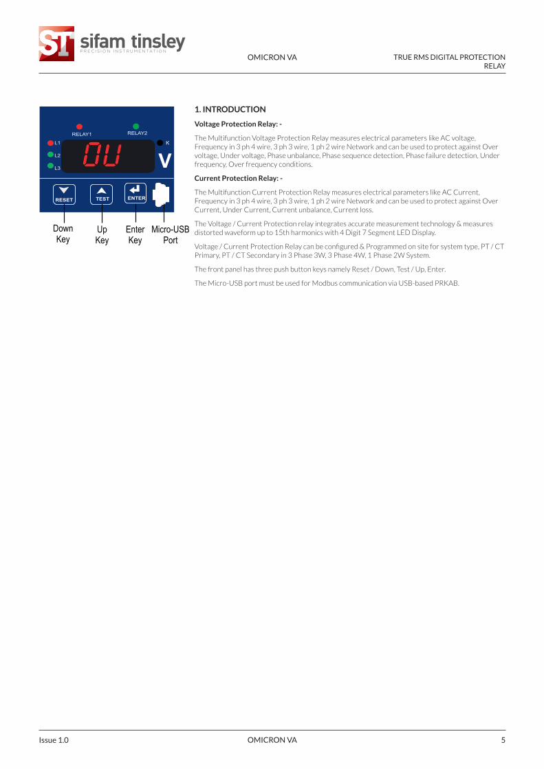
The front panel has three push button keys namely Reset / Down, Test / Up, Enter.
The Micro-USB port must be used for Modbus communication via USB-based PRKAB.
DownKey
UpKey
EnterKey
Micro-USBPort
L3
L2
L1
RELAY1 RELAY2
ENTERTESTRESET
K
V
OMICRON VA TRUE RMS DIGITAL PROTECTION RELAY
OMICRON VA Issue 1.06
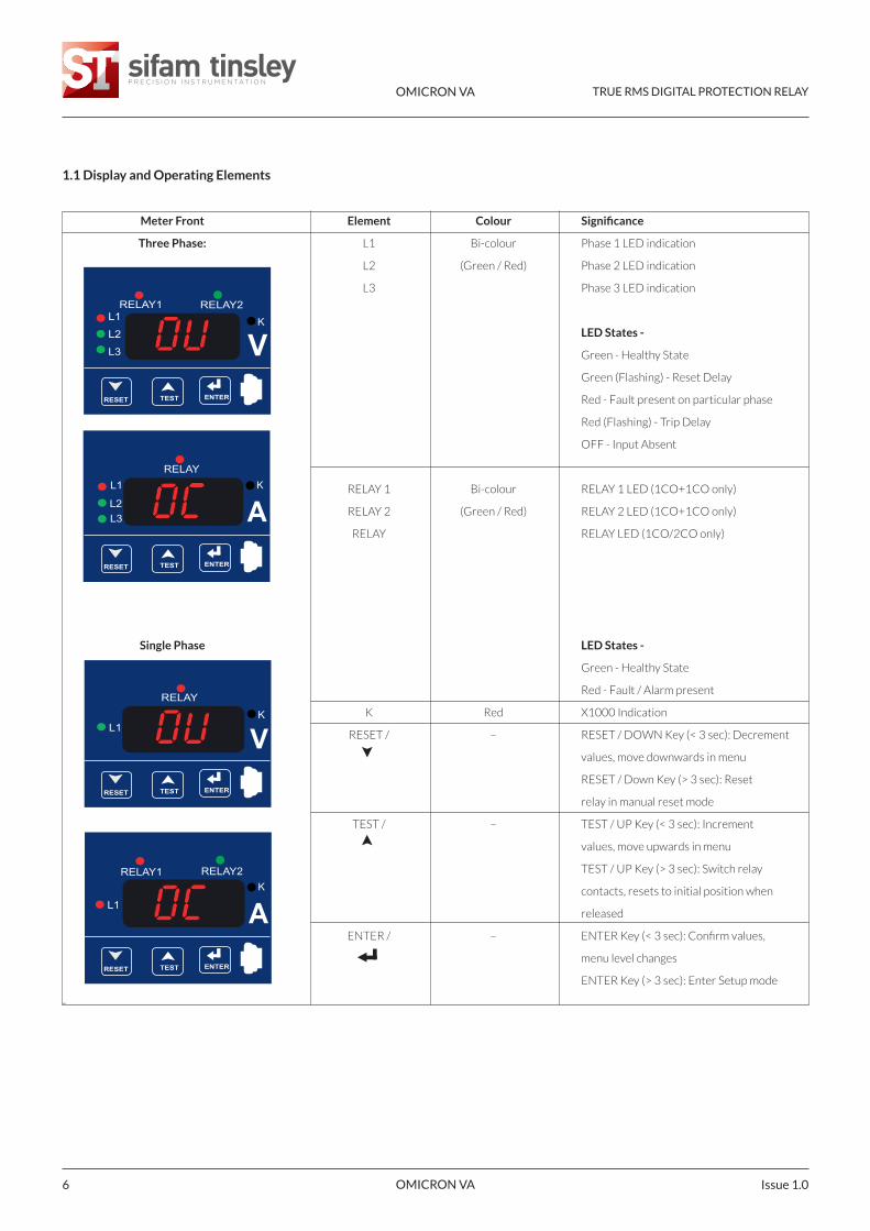
1.1 Display and Operating Elements
Meter Front Element Colour Significance
Three Phase: L1 Bi-colour Phase 1 LED indication
L2 (Green / Red) Phase 2 LED indication
L3 Phase 3 LED indication
LED States -
Green - Healthy State
Green (Flashing) - Reset Delay
Red - Fault present on particular phase
Red (Flashing) - Trip Delay
OFF - Input Absent
RELAY 1 Bi-colour RELAY 1 LED (1CO+1CO only)
RELAY 2 (Green / Red) RELAY 2 LED (1CO+1CO only)
RELAY RELAY LED (1CO/2CO only)
Single Phase LED States -
Green - Healthy State
Red - Fault / Alarm present
K Red X1000 Indication
RESET / – RESET / DOWN Key (< 3 sec): Decrement
values, move downwards in menu
RESET / Down Key (> 3 sec): Reset
relay in manual reset mode
TEST / – TEST / UP Key (< 3 sec): Increment
values, move upwards in menu
TEST / UP Key (> 3 sec): Switch relay
contacts, resets to initial position when
released
ENTER / – ENTER Key (< 3 sec): Confirm values,
menu level changes
ENTER Key (> 3 sec): Enter Setup mode
-
L3
L2
L1RELAY1 RELAY2
ENTERTESTRESET
K
V
L3L2
L1RELAY
AK
ENTERTESTRESET
L1
RELAY
K
VENTERTESTRESET
L1
RELAY1 RELAY2
AK
ENTERTESTRESET
OMICRON VA TRUE RMS DIGITAL PROTECTION RELAY
OMICRON VA 7Issue 1.0
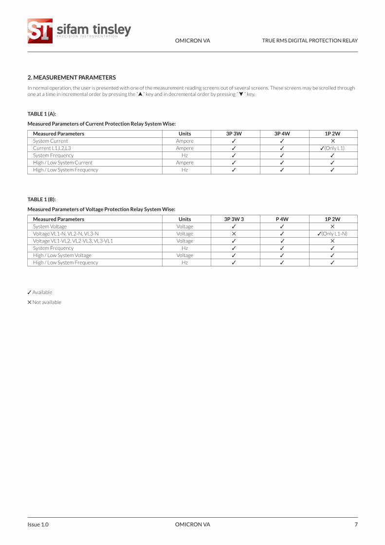
2. MEASUREMENT PARAMETERS
In normal operation, the user is presented with one of the measurement reading screens out of several screens. These screens may be scrolled throughone at a time in incremental order by pressing the “ “ key and in decremental order by pressing “ ” key.
TABLE 1 (A):
Measured Parameters of Current Protection Relay System Wise:
Measured Parameters Units 3P 3W 3P 4W 1P 2WSystem Current Ampere ✓ ✓ ✕
Current L1,L2,L3 Ampere ✓ ✓ ✓(Only L1)
System Frequency Hz ✓ ✓ ✓
High / Low System Current Ampere ✓ ✓ ✓
High / Low System Frequency Hz ✓ ✓ ✓
TABLE 1 (B):
Measured Parameters of Voltage Protection Relay System Wise:
Measured Parameters Units 3P 3W 3 P 4W 1P 2WSystem Voltage Voltage ✓ ✓ ✕
Voltage VL1-N, VL2-N, VL3-N Voltage ✕ ✓ ✓(Only L1-N)
Voltage VL1-VL2, VL2-VL3, VL3-VL1 Voltage ✓ ✓ ✕
System Frequency Hz ✓ ✓ ✓
High / Low System Voltage Voltage ✓ ✓ ✓
High / Low System Frequency Hz ✓ ✓ ✓
✓ Available
✕ Not available
OMICRON VA TRUE RMS DIGITAL PROTECTION RELAY
OMICRON VA Issue 1.08
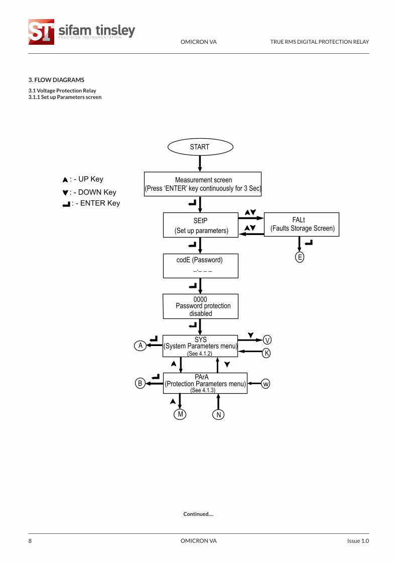
3. FLOW DIAGRAMS
3.1 Voltage Protection Relay3.1.1 Set up Parameters screen
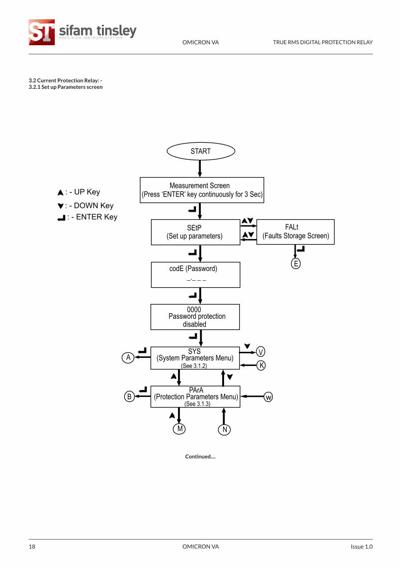
START
Measurement screen(Press ‘ENTER’ key continuously for 3 Sec)
SEtP(Set up parameters)
FALt (Faults Storage Screen)
codE (Password) _._ _ _
0000Password protection
disabled
SYS(System Parameters menu) (See 4.1.2)
A VK
E
B
M N
: - UP Key
: - DOWN Key: - ENTER Key
wPArA
(Protection Parameters menu) (See 4.1.3)
Continued....
OMICRON VA TRUE RMS DIGITAL PROTECTION RELAY
OMICRON VA 9Issue 1.0
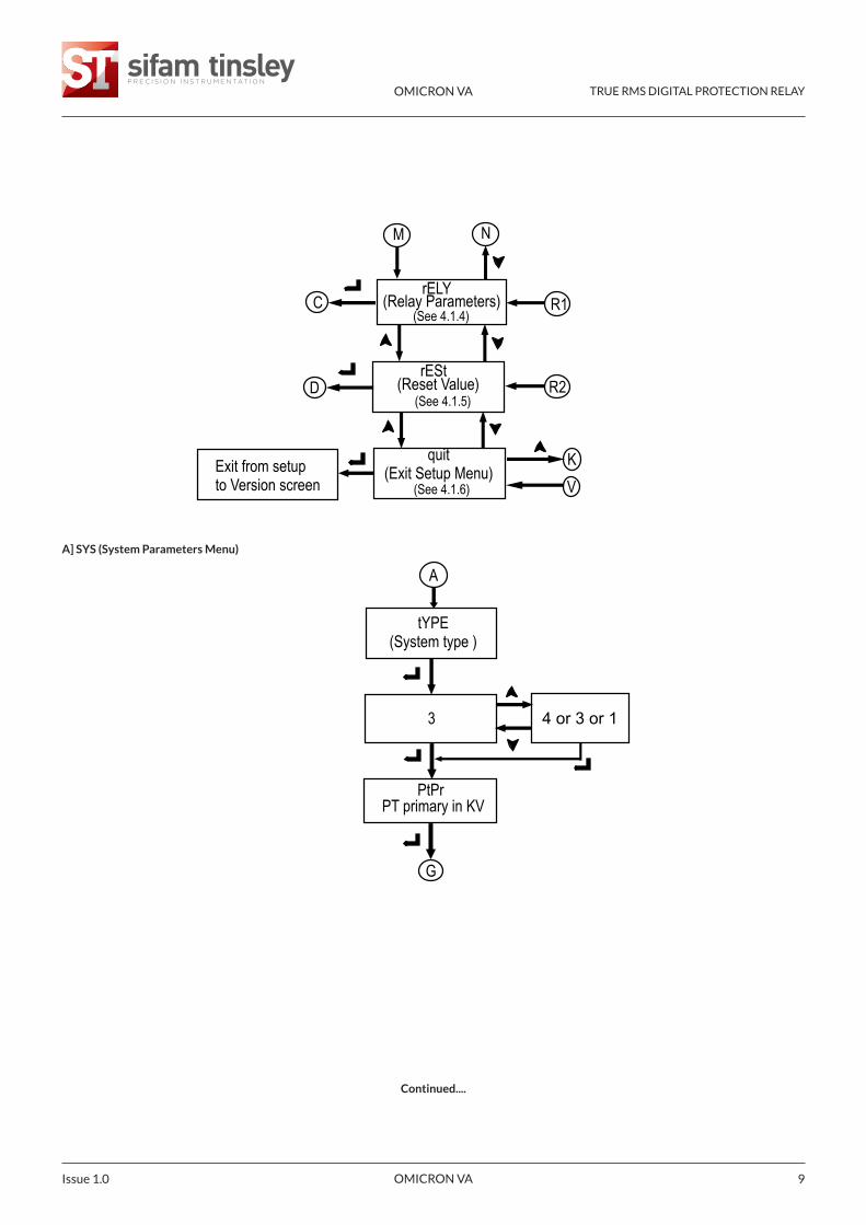
Continued....
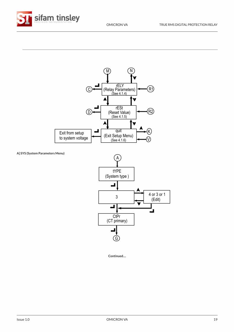
Exit from setup to Version screen
C
D
KV
A
tYPE(System type )
3
PT primary in KVPtPr
G
4 or 3 or 1
M N
R1
R2
rELY(Relay Parameters)
(See 4.1.4)
rESt(Reset Value)
(See 4.1.5)
quit (Exit Setup Menu)
(See 4.1.6)
A] SYS (System Parameters Menu)
OMICRON VA TRUE RMS DIGITAL PROTECTION RELAY
OMICRON VA Issue 1.010
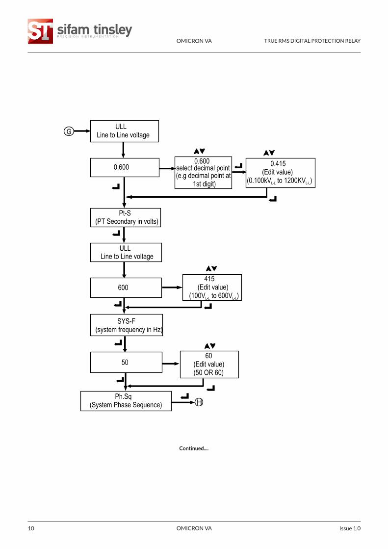
Continued....
ULLLine to Line voltage
0.6000.600
select decimal point(e.g decimal point at 1st digit)
0.415 (Edit value)(0.100kV to 1200KV )L-L L-L
Pt-S(PT Secondary in volts)
ULLLine to Line voltage
600 415 (Edit value)(100V to 600V )L-L L-L
SYS-F(system frequency in Hz)
50
G
Ph.Sq(System Phase Sequence) H
60(Edit value)(50 OR 60)
OMICRON VA TRUE RMS DIGITAL PROTECTION RELAY
OMICRON VA 11Issue 1.0
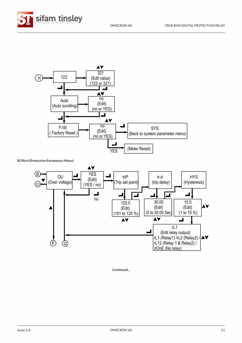
Auto (Auto scrolling)
no (Edit) (no or YES)
H 123 321 (Edit value) (123 or 321)
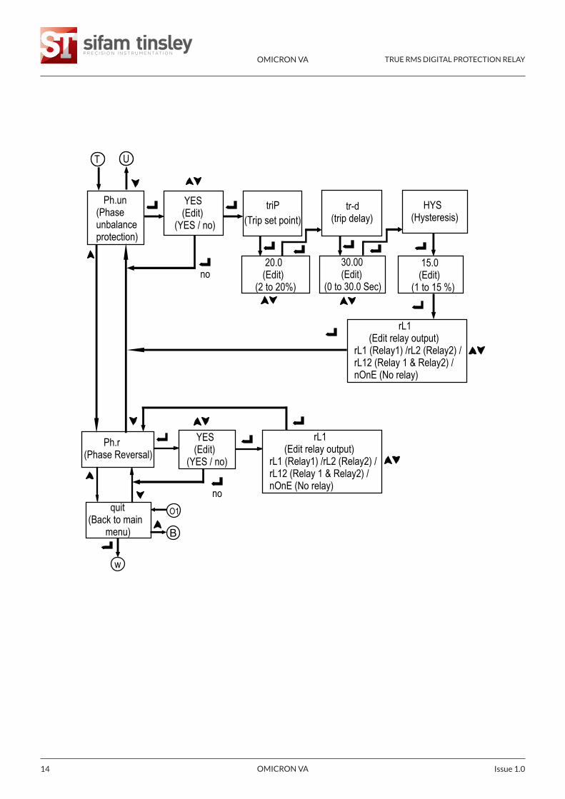
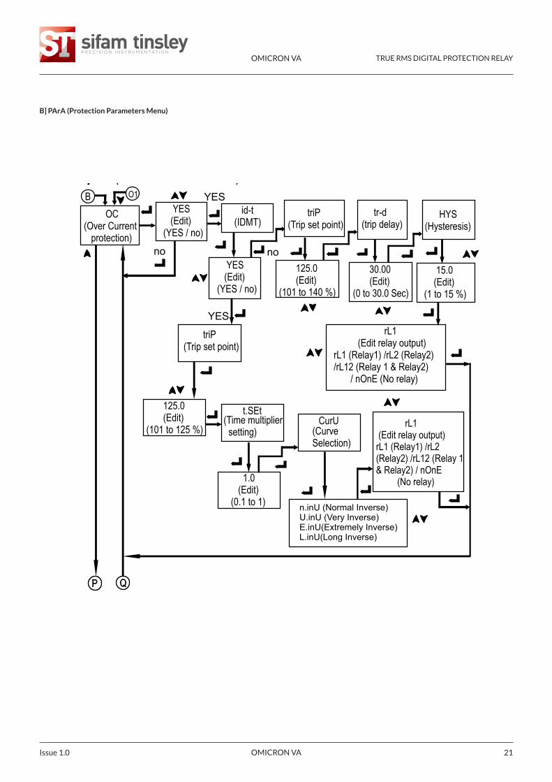
OU (Over voltage)
B YES (Edit) (YES / no)
triP(Trip set point)
tr-d(trip delay)
HYS (Hysteresis)
rL1 (Edit relay output) rL1 (Relay1) /rL2 (Relay2) / rL12 (Relay 1 & Relay2) / nOnE (No relay)
125.0 (Edit)(101 to 125 %)
30.00 (Edit)(0 to 30.00 Sec)
15.0 (Edit)(1 to 15 %)
P Q
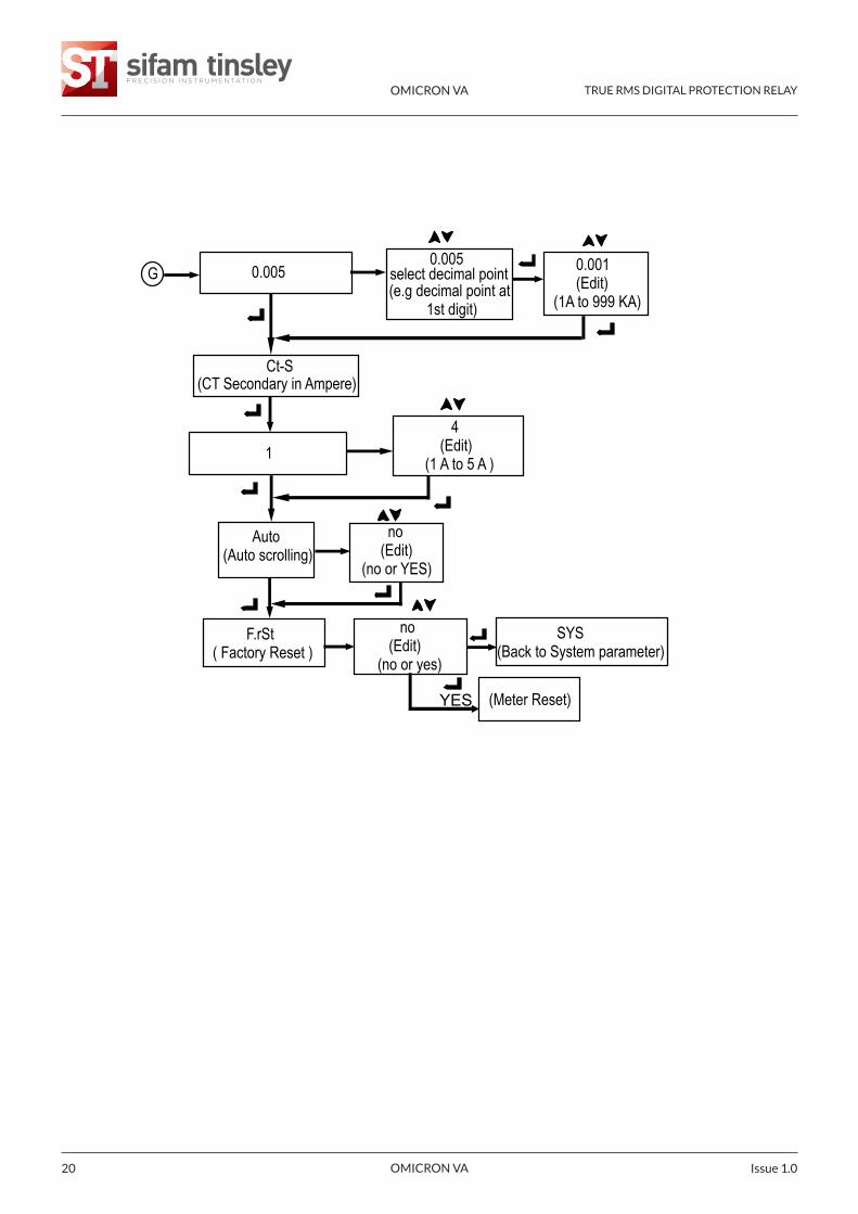
F.rSt ( Factory Reset )
SYS (Back to system parameter menu)
(Meter Reset)
no (Edit)(no or YES)
YES
no
O1
B] PArA (Protection Parameters Menu)
Continued...
OMICRON VA TRUE RMS DIGITAL PROTECTION RELAY
OMICRON VA Issue 1.012
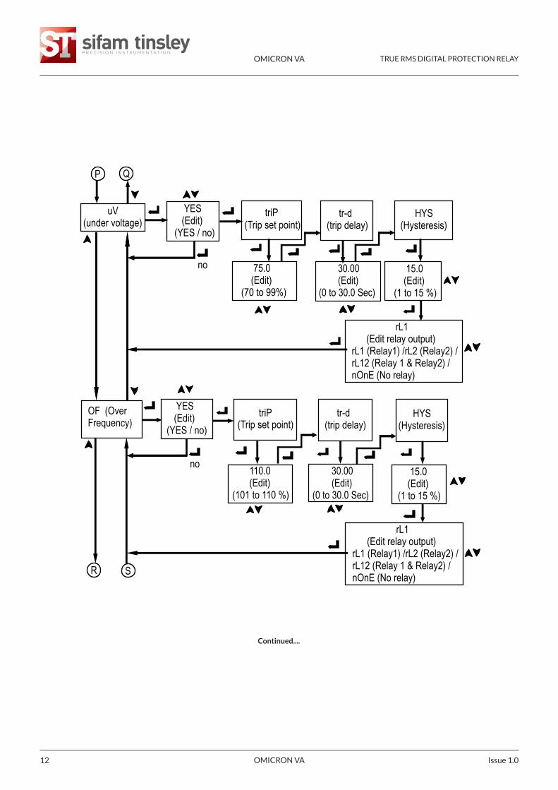
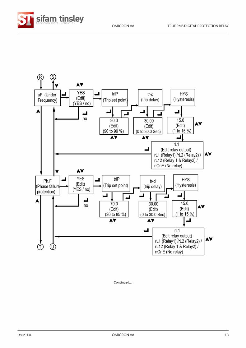
Continued....
uV(under voltage)
YES (Edit) (YES / no)
(Trip set point)triP tr-d
(trip delay) HYS (Hysteresis)
75.0 (Edit) (70 to 99%)
30.00 (Edit) (0 to 30.0 Sec)
P Q
OF (Over Frequency)
triP
110.0 (Edit) (101 to 110 %)
P Q
R SR S
15.0 (Edit)(1 to 15 %)
15.0 (Edit)(1 to 15 %)
rL1 (Edit relay output) rL1 (Relay1) /rL2 (Relay2) / rL12 (Relay 1 & Relay2) / nOnE (No relay)
YES (Edit) (YES / no)
(Trip set point) tr-d(trip delay)
HYS (Hysteresis)
30.00 (Edit) (0 to 30.0 Sec)
rL1 (Edit relay output) rL1 (Relay1) /rL2 (Relay2) / rL12 (Relay 1 & Relay2) / nOnE (No relay)
no
no
OMICRON VA TRUE RMS DIGITAL PROTECTION RELAY
OMICRON VA 13Issue 1.0
Continued....
OMICRON VA TRUE RMS DIGITAL PROTECTION RELAY
OMICRON VA Issue 1.014
OMICRON VA TRUE RMS DIGITAL PROTECTION RELAY
OMICRON VA 15Issue 1.0
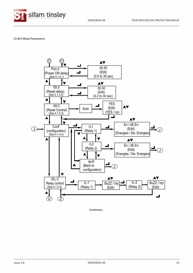
C] rELY (Relay Parameters)
Continued....
C
00.50 (Edit) (0.5 to 30 sec)
00.50 (Edit) (0.2 to 30 sec)
Auto
En / dE.En (Edit)(Energies / De- Energies)
rEL.CRelay control rL-1
(Relay 1)
YES (Edit) (YES / no)
rL1 (Relay 1)
rL2 (Relay 2)
quit(Back to configuration)
En / dE.En (Edit)(Energies / De- Energies)
J J
J
BuZZ / trip (Edit)
rL-2 (Relay 2)
BuZZ / trip (Edit)
U Z
Pon.d(Power ON delay)
(See 4.1.4.1)
rSt.d(Reset delay)
(See 4.1.4.2)
rSt.C(Reset Control)
(See 4.1.4.3)
ConF (configuration)
(See 4.1.4.4)
(See 4.1.4.5)
J
P1
OMICRON VA TRUE RMS DIGITAL PROTECTION RELAY
OMICRON VA Issue 1.016
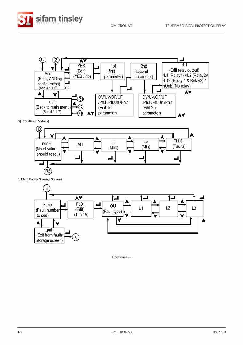
Continued....
E
Ft.no (Fault number to see)
OU(Fault type) L1 L2 L3
quit (Exit from faults storage screen)
D
nonE(No of value should reset )
ALL Hi (Max)
Lo (Min)
FLt.S(Faults)
R2
Ft.01 (Edit)(1 to 15)
R1
1st (first parameter)
2nd (second parameter)
OV/UV/OF/UF/Ph.F/Ph.Un /Ph.r(Edit 1st parameter)
OV/UV/OF/UF/Ph.F/Ph.Un /Ph.r(Edit 2nd parameter)
U Z YES (Edit) (YES / no)
no
C
X
rL1 (Edit relay output) rL1 (Relay1) /rL2 (Relay2)/ rL12 (Relay 1 & Relay2) / nOnE (No relay)
And(Relay ANDingconfiguration)(See 4.1.4.6)
quit(Back to main menu)
(See 4.1.4.7) P1
D] rESt (Reset Values)
E] FALt (Faults Storage Screen)
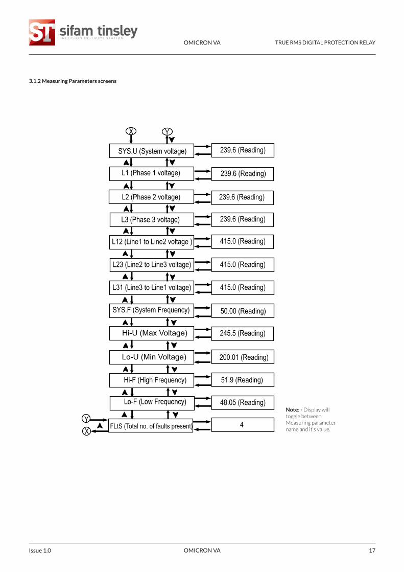
SYS.U (System voltage)
L1 (Phase 1 voltage)
L3 (Phase 3 voltage)
L2 (Phase 2 voltage)
L12 (Line1 to Line2 voltage )
L31 (Line3 to Line1 voltage)
L23 (Line2 to Line3 voltage)
SYS.F (System Frequency)
Hi-U (Max Voltage)
Lo-U (Min Voltage)
Hi-F (High Frequency)
Lo-F (Low Frequency)
239.6 (Reading)
239.6 (Reading)
239.6 (Reading)
415.0 (Reading)
415.0 (Reading)
239.6 (Reading)
415.0 (Reading)
200.01 (Reading)
51.9 (Reading)
48.05 (Reading)
50.00 (Reading)
245.5 (Reading)
X Y
XY
FLtS (Total no. of faults present) 4
OMICRON VA TRUE RMS DIGITAL PROTECTION RELAY
OMICRON VA 17Issue 1.0
3.1.2 Measuring Parameters screens
Note: - Display willtoggle betweenMeasuring parametername and it's value.
OMICRON VA TRUE RMS DIGITAL PROTECTION RELAY
OMICRON VA Issue 1.018
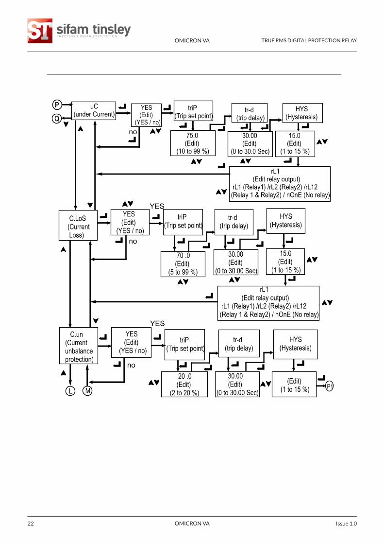
3.2 Current Protection Relay: -3.2.1 Set up Parameters screen
Continued....
OMICRON VA TRUE RMS DIGITAL PROTECTION RELAY
OMICRON VA 19Issue 1.0
Continued....
A] SYS (System Parameters Menu)
OMICRON VA TRUE RMS DIGITAL PROTECTION RELAY
OMICRON VA Issue 1.020
OMICRON VA TRUE RMS DIGITAL PROTECTION RELAY
OMICRON VA 21Issue 1.0
B] PArA (Protection Parameters Menu)
OMICRON VA TRUE RMS DIGITAL PROTECTION RELAY
OMICRON VA Issue 1.022
C
00.50 (Edit) (0.5 to 30 sec)
00.50 (Edit) (0.2 to 30 sec)
Auto
En / dE.En (Edit)(Energies / De- Energies)
YES (Edit) (YES / no)
rL1 (Relay 1)
rL2 (Relay 2) quit(Back to configuration)
En / dE.En (Edit)(Energies / De- Energies)
J J
J
U Z
Pon.d(Power ON delay)
(See 4.1.4.1)
rSt.d(Reset delay)
(See 4.1.4.2)
rSt.C(Reset Control)
(See 4.1.4.3)
COnF (configuration)
(See 4.1.4.4)
quit(Back to main menu)
W
rL1 (Edit relay output) rL1 (Relay1) /rL2 (Relay2) /rL12 (Relay 1 & Relay2) / nOnE (No relay) B
P1
L M
V1
O1
OMICRON VA TRUE RMS DIGITAL PROTECTION RELAY
OMICRON VA 23Issue 1.0
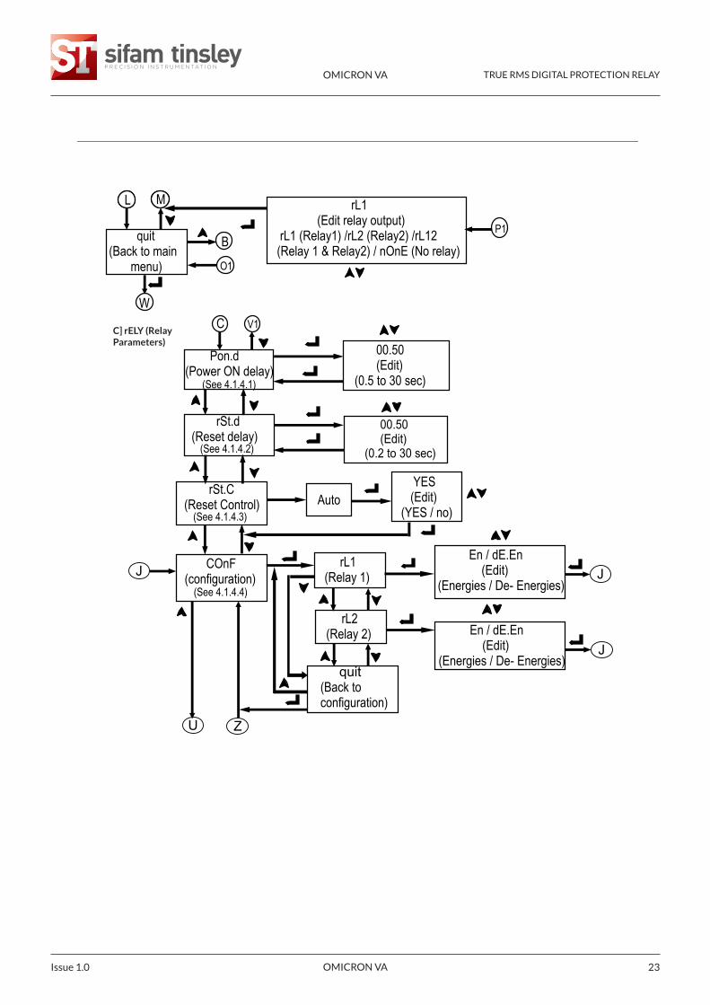
C] rELY (RelayParameters)
OMICRON VA TRUE RMS DIGITAL PROTECTION RELAY
OMICRON VA Issue 1.024
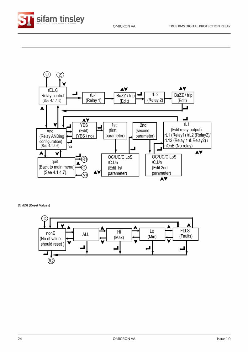
D] rESt (Reset Values)
OMICRON VA TRUE RMS DIGITAL PROTECTION RELAY
OMICRON VA 25Issue 1.0
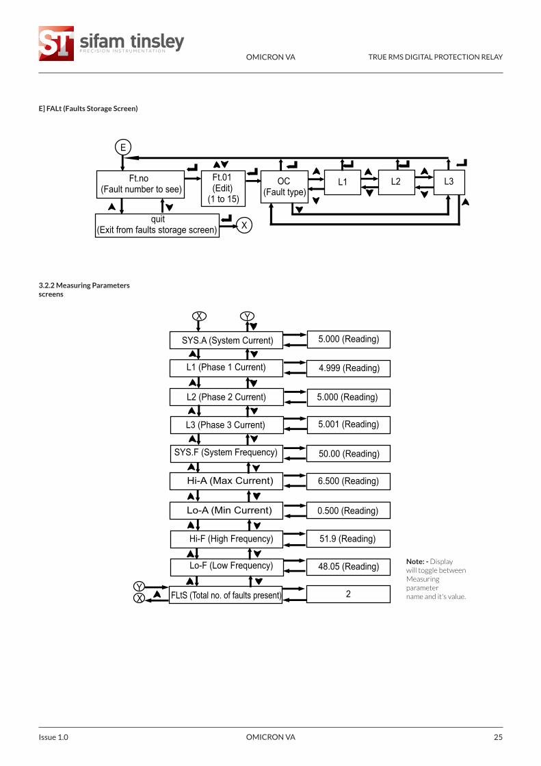
E] FALt (Faults Storage Screen)
3.2.2 Measuring Parametersscreens
E
Ft.no (Fault number to see)
OC(Fault type)
L1 L2 L3
quit (Exit from faults storage screen)
Ft.01 (Edit)(1 to 15)
X
SYS.A (System Current)
L1 (Phase 1 Current)
L3 (Phase 3 Current)
L2 (Phase 2 Current)
SYS.F (System Frequency)
Hi-A (Max Current)
Lo-A (Min Current)
Hi-F (High Frequency)
Lo-F (Low Frequency)
5.000 (Reading)
5.000 (Reading)
4.999 (Reading)
5.001 (Reading)
0.500 (Reading)
51.9 (Reading)
48.05 (Reading)
50.00 (Reading)
6.500 (Reading)
X Y
XY
2 FLtS (Total no. of faults present)
Note: - Displaywill toggle betweenMeasuringparametername and it's value.
OMICRON VA TRUE RMS DIGITAL PROTECTION RELAY
OMICRON VA Issue 1.026
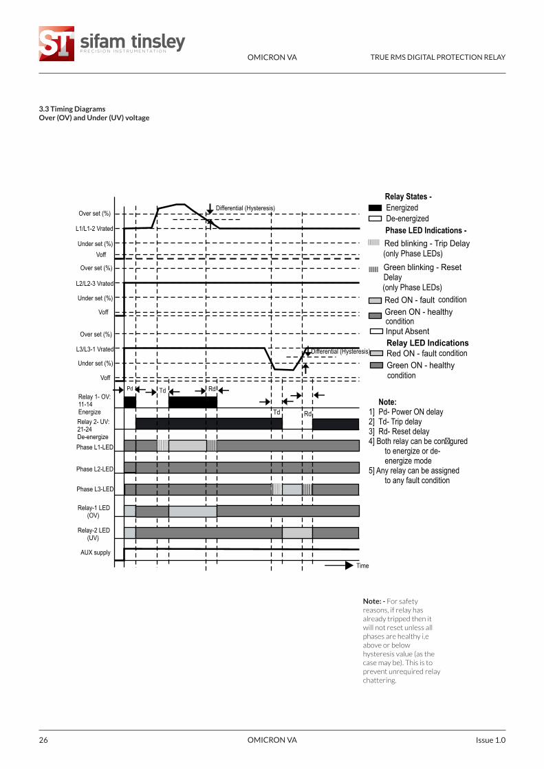
3.3 Timing DiagramsOver (OV) and Under (UV) voltage
Note: - For safetyreasons, if relay hasalready tripped then itwill not reset unless allphases are healthy i.eabove or belowhysteresis value (as thecase may be). This is toprevent unrequired relaychattering.
Note:1] Pd- Power ON delay2] Td- Trip delay3] Rd- Reset delay4] Both relay can be con�gured
to energize or de-energize mode
5] Any relay can be assigned to any fault condition
Red blinking - Trip Delay
Green blinking - Reset
Red ON - fault Green ON - healthy
Red ON - fault Green ON - healthy
Relay LED Indications Input Absent
condition
condition
condition
condition(only Phase LEDs)Delay
(only Phase LEDs)
Over set (%)
L1/L1-2 Vrated
Under set (%) Voff
Over set (%)
L2/L2-3 Vrated
Under set (%)
Voff
Over set (%)
L3/L3-1 Vrated
Voff
Phase L1-LED
Phase L2-LED
Phase L3-LED
Relay-1 LED (OV)
Relay-2 LED (UV)
AUX supply
Relay 2- UV: 21-24De-energize
Relay 1- OV: 11-14 Energize
Differential (Hysteresis)
Differential (Hysteresis)
Pd Td Rd
Td Rd
Time
EnergizedDe-energized
Relay States -
Phase LED Indications -
Under set (%)
27 of 68
L1/L1-2 Vrated
Phase fail set (%) Voff
Phase fail set (%) Voff
L2/L2-3 Vrated
L3/L3-1 Vrated
Phase fail set (%)
Voff
Relay 1- Ph.F:11-14 EnergizeRelay 2- Ph.un:21-24De-energizePhase L1-LED
Phase L2-LED
Phase L3-LED
Relay-1 LED (Ph.F)
Relay-2 LED (Ph.un)
AUX supply
Differential (Hysteresis)
Differential (Hysteresis)
Unbalance
Unbalance
Pd Td Rd Td Rd
Time
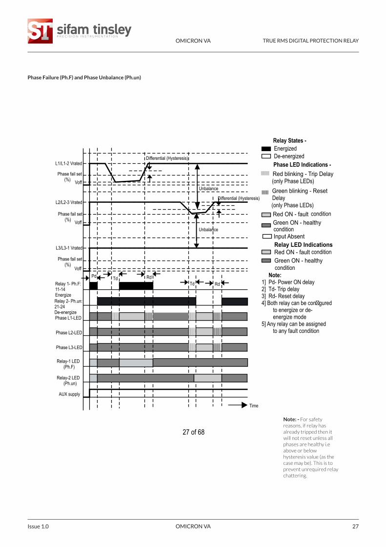
Note:1] Pd- Power ON delay2] Td- Trip delay3] Rd- Reset delay4] Both relay can be con�gured
to energize or de-energize mode
5] Any relay can be assigned to any fault condition
Red blinking - Trip Delay
Green blinking - Reset
Red ON - fault Green ON - healthy
Red ON - fault Green ON - healthy
Relay LED Indications Input Absent
condition
condition
condition
condition(only Phase LEDs)Delay
(only Phase LEDs)
EnergizedDe-energized
Relay States -
Phase LED Indications -
OMICRON VA TRUE RMS DIGITAL PROTECTION RELAY
OMICRON VA 27Issue 1.0
Phase Failure (Ph.F) and Phase Unbalance (Ph.un)
Note: - For safetyreasons, if relay hasalready tripped then itwill not reset unless allphases are healthy i.eabove or belowhysteresis value (as thecase may be). This is toprevent unrequired relaychattering.
OMICRON VA TRUE RMS DIGITAL PROTECTION RELAY
OMICRON VA Issue 1.028
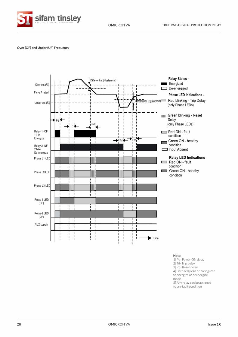
Over (OF) and Under (UF) Frequency
Note:1] Pd- Power ON delay2] Td- Trip delay3] Rd- Reset delay4] Both relay can be configuredto energize or deenergizemode5] Any relay can be assignedto any fault condition
Red blinking - Trip Delay
Green blinking - Reset
Red ON - fault
Green ON - healthy
Red ON - fault
Green ON - healthy
Relay LED Indications
Input Absent
condition
condition
condition
condition
(only Phase LEDs)Delay
(only Phase LEDs)
EnergizedDe-energized
Relay States -
Phase LED Indications -
Over set (%)
F sys F rated
Under set (%)
Relay 1- OF: 11-14Energize
Relay 2- UF: 21-24De-energize
Phase L1-LED
Phase L2-LED
Phase L3-LED
Relay-1 LED (OF)
Relay-2 LED (UF)
AUX supply
Time
Differential (Hysteresis)
Differential (Hysteresis)
Pd
Td Rd
Td Rd
OMICRON VA TRUE RMS DIGITAL PROTECTION RELAY
OMICRON VA 29Issue 1.0
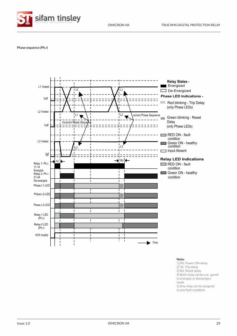
Phase sequence (Ph.r)
Note:1] Pd- Power ON delay2] Td- Trip delay3] Rd- Reset delay4] Both relay can be conguredto energize or deenergizemode5] Any relay can be assignedto any fault condition
Voff
EnergizedDe-Energized
Red blinking - Trip Delay
Green blinking - Reset
RED ON - fault
Green ON - healthy
Relay States -
Phase LED Indications -
RED ON - fault
Green ON - healthy
Relay LED Indications
Input Absent
condition
condition
condition
condition
(only Phase LEDs)Delay
(only Phase LEDs)
L1 Vrated
Voff
L2 Vrated
Voff
L3 Vrated
Relay 1- Ph.r: 11-14EnergizeRelay 2- Ph.r: 21-24De-energize
Phase L2-LED
Phase L3-LED
Relay-1 LED (Ph.r)
Relay-2 LED (Ph.r)
AUX supply
Phase L1-LED
L2
L1
L1
L2
Incorrect Phase Sequence
correct Phase Sequence
L3 L3
Pd Rd
Time
OMICRON VA TRUE RMS DIGITAL PROTECTION RELAY
OMICRON VA Issue 1.030
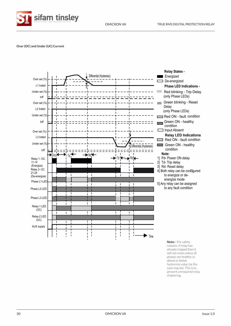
Over (OC) and Under (UC) Current
Differential (Hysteresis)
Pd Td Rd Td Rd
Time
Differential (Hysteresis) Over set (%)
L1 Irated
Under set (%)
Ioff
Over set (%)
L2 Irated
Under set (%)
Ioff
Over set (%)
L3 Irated
Under set (%)
Ioff
Relay 1- OC: 11-14(Energize)Relay 2- UC: 21-24(De-energize)
Phase L2-LED
Phase L3-LED
Relay-1 LED (OC)
Relay-2 LED (UC)
AUX supply
Phase L1-LED
Note:1] Pd- Power ON delay2] Td- Trip delay3] Rd- Reset delay4] Both relay can be con�gured
to energize or de-energize mode
5] Any relay can be assigned to any fault condition
Red blinking - Trip Delay
Green blinking - Reset
Red ON - fault Green ON - healthy
Red ON - fault Green ON - healthy
Relay LED Indications Input Absent
condition
condition
condition
condition(only Phase LEDs)Delay
(only Phase LEDs)
EnergizedDe-energized
Relay States -
Phase LED Indications -
Note: - For safetyreasons, if relay hasalready tripped then itwill not reset unless allphases are healthy i.eabove or belowhysteresis value (as thecase may be). This is toprevent unrequired relaychattering.
OMICRON VA TRUE RMS DIGITAL PROTECTION RELAY
OMICRON VA 31Issue 1.0
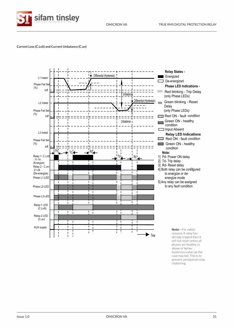
Current Loss (C.LoS) and Current Unbalance (C.un)
Pd Td Rd Td Rd
Time
Differential (Hysteresis)
Unbalance
Differential (Hysteresis)
Unbalance
L1 Irated
Phase Fail Set(%)
Ioff
L2 Irated
Phase Fail Set(%)
Ioff
L3 Irated
Phase Fail Set(%)
Ioff
Relay 1- C.LoS: 11-14(Energize)Relay 2 - C.un: 21-24(De-energize)
Phase L2-LED
Phase L3-LED
Relay-1 LED (C.LoS)
Relay-2 LED (C.un)
AUX supply
Phase L1-LED
Note:1] Pd- Power ON delay2] Td- Trip delay3] Rd- Reset delay4] Both relay can be con�gured
to energize or de-energize mode
5] Any relay can be assigned to any fault condition
Red blinking - Trip Delay
Green blinking - Reset
Red ON - fault Green ON - healthy
Red ON - fault Green ON - healthy
Relay LED Indications Input Absent
condition
condition
condition
condition(only Phase LEDs)Delay
(only Phase LEDs)
EnergizedDe-energized
Relay States -
Phase LED Indications -
Note: - For safetyreasons, if relay hasalready tripped then itwill not reset unless allphases are healthy i.eabove or belowhysteresis value (as thecase may be). This is toprevent unrequired relaychattering.
OMICRON VA TRUE RMS DIGITAL PROTECTION RELAY
OMICRON VA Issue 1.032
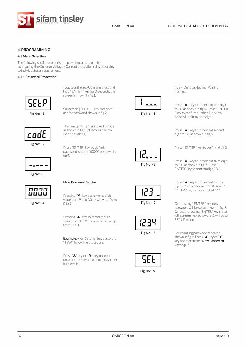
4. PROGRAMMING
4.1 Menu Selection
The following sections comprise step by step procedures forconfiguring the Omicron Voltage / Current protection relay accordingto individual user requirement.
4.1.1 Password Protection
To access the Set-Up menu press andhold “ ENTER ” key for 3 Seconds, thescreen is shown in fig 1.
On pressing “ENTER” key, meter willask for password shown in fig 2.
Then meter will enter into edit modeas shown in fig 3 (*Denotes decimalPoint is flashing).
Press “ENTER” key, by defaultpassword is set to “0000" as shown infig 4.
New Password Setting
Pressing “ ” key decrements digitvalue from 9 to 0. Value will wrap from0 to 9.
Pressing “ ” key increments digitvalue from 0 to 9, then value will wrapfrom 9 to 0.
Example: - For Setting New password“1234" follow the procedure.
Press “ ” key or “ ” key once, toenter into password edit mode, screenis shown in
Fig No: - 1
Fig No: - 2
Fig No: - 3
Fig No: - 4
fig 3 (*Denotes decimal Point isflashing).
Press “ ” key to increment first digitto ‘ 1 ‘ as shown in fig 5. Press “ ENTER” key to confirm number 1, decimalpoint will shift to next digit.
Press “ ” key to increment seconddigit to ‘ 2 ’ as shown in fig 6.
Press “ ENTER “ key to confirm digit 2.
Press “ ” key to increment third digitto “ 3 “ as shown in fig 7. Press “ENTER” key to confirm digit “ 3 “.
Press “ ” key to increment fourthdigit to “ 4 ” as shown in fig 8. Press “ENTER ” key to confirm digit “ 4 ”.
On pressing “ ENTER ” key newpassword will be set as shown in fig 9.On again pressing “ENTER” key meterwill confirm new password & will go toSET UP menu.
For changing password at screenshown in fig 9, Press “ ” key or “ ”key and start from “New PasswordSetting: -”
Fig No: - 5
Fig No: - 6
Fig No: - 7
Fig No: - 8
Fig No: - 9
**
OMICRON VA TRUE RMS DIGITAL PROTECTION RELAY
OMICRON VA 33Issue 1.0
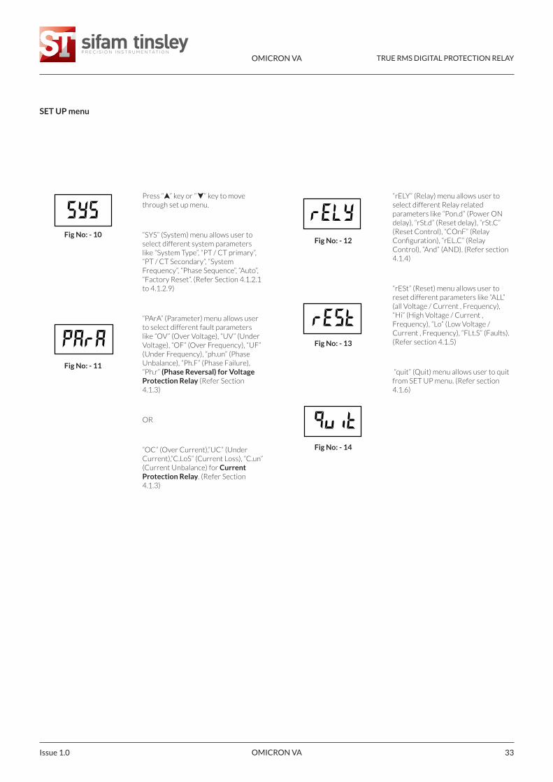
SET UP menu
Press “ ” key or “ ” key to movethrough set up menu.
“SYS” (System) menu allows user toselect different system parameterslike “System Type”, “PT / CT primary”,“PT / CT Secondary”, “SystemFrequency”, “Phase Sequence”, “Auto”,“Factory Reset”. (Refer Section 4.1.2.1to 4.1.2.9)
“PArA” (Parameter) menu allows userto select different fault parameterslike “OV” (Over Voltage), “UV” (UnderVoltage), “OF” (Over Frequency), “UF”(Under Frequency), “ph.un” (PhaseUnbalance), “Ph.F” (Phase Failure),“Ph.r” (Phase Reversal) for VoltageProtection Relay (Refer Section4.1.3)
OR
“OC” (Over Current),”UC” (UnderCurrent),”C.LoS” (Current Loss), “C.un”(Current Unbalance) for CurrentProtection Relay. (Refer Section4.1.3)
Fig No: - 10
Fig No: - 11
“rELY” (Relay) menu allows user toselect different Relay relatedparameters like “Pon.d” (Power ONdelay), “rSt.d” (Reset delay), “rSt.C”(Reset Control), “COnF” (RelayConfiguration), “rEL.C” (RelayControl), “And” (AND). (Refer section4.1.4)
“rESt” (Reset) menu allows user toreset different parameters like “ALL”(all Voltage / Current , Frequency),“Hi” (High Voltage / Current ,Frequency), “Lo” (Low Voltage /Current , Frequency), “FLt.S” (Faults).(Refer section 4.1.5)
“quit” (Quit) menu allows user to quitfrom SET UP menu. (Refer section4.1.6)
Fig No: - 12
Fig No: - 13
Fig No: - 14

OMICRON VA TRUE RMS DIGITAL PROTECTION RELAY
OMICRON VA Issue 1.034
4.1.2 System Parameter Selection Menu
4.1.2.1 System Type
“SYS” (System) menu allows user toset system parameters.
On pressing “ENTER” key meter willenter into system parameters & askfor system type selection as shown infig 16.
This screen is used to set the systemtype (only for 3 phase meter), 3 for3P3W, 4 for 3P4W & 1 for 1P2W.
Now the screen will show previouslystored system type “4” as shown in fig:- 17.
Setting New system Type: -
Pressing “ ” or “ ” key, meter willenter into edit mode.
Pressing “ ” key increments digitvalue & Pressing “ ” key decrementsdigit value.
Example: -
For Setting new system type “3"follow the procedure: - Press “ ” keyor “ ” key to get number “3 “ asshown in fig 18.
Fig No: - 15
Fig No: - 16
Fig No: - 17
Fig No: - 18
Fig No: - 19
On pressing “ ENTER ” key newsystem type will be set as shown in fig19. On again pressing “ENTER” keymeter will confirm new system type &will go to PT primary setting (forVoltage Protection Relay) (referSection 4.1.2.2) or to CT primarysetting (for Current protection relay)(refer Section 4.1.2.4)
Fig No: - 20
Fig No: - 21
Fig No: - 22
Fig No: - 23
4.1.2.2 Potential Transformer (PT) PrimaryV-Line to LineVoltage Protection Relay: -
This Screen allows user toset Potential Transformer’sprimary value in KV. K isindicated by annunciation of‘K’ LED.The PT primary can be set from0.100 KV to 1200 KV . L-L L-L
“ PtPr ” (Potential transformerprimary) is shown in fig 20 &“VLL” (Line to Line Voltage) isshown in fig 21.
After VLL, meter will showpreviously stored PtPr value“ 0.415 “ (415 VL-L) as shown infig 22 and “ K ” LED will be litwhich indicate that the PTprimary is in KV .*
OMICRON VA TRUE RMS DIGITAL PROTECTION RELAY
OMICRON VA 35Issue 1.0
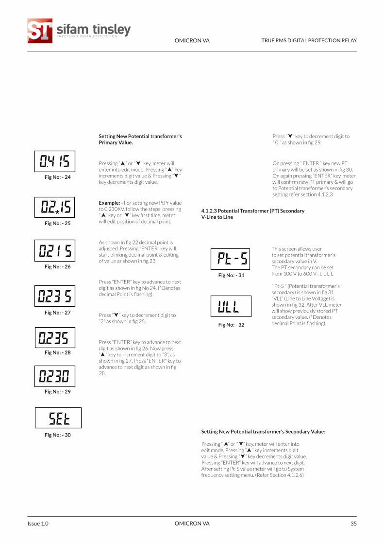
Setting New Potential transformer'sPrimary Value.
Pressing “ ” or “ ” key, meter willenter into edit mode. Pressing “ ” keyincrements digit value & Pressing “ ”key decrements digit value.
Example: - For setting new PtPr valueto 0.230KV, follow the steps: pressing“ ” key or “ ” key first time, meterwill edit position of decimal point.
As shown in fig 22 decimal point isadjusted. Pressing “ENTER” key willstart blinking decimal point & editingof value as shown in fig 23.
Press “ENTER” key to advance to nextdigit as shown in fig No 24. (*Denotesdecimal Point is flashing).
Press “ ” key to decrement digit to“2” as shown in fig 25.
Press “ENTER” key to advance to nextdigit as shown in fig 26. Now press “ ” key to increment digit to “3”, asshown in fig 27. Press “ENTER” key toadvance to next digit as shown in fig28.
Fig No: - 24
Fig No: - 25
Fig No: - 26
Fig No: - 27
Fig No: - 28
Fig No: - 29
Fig No: - 30
Press “ ” key to decrement digit to “ 0 ” as shown in fig 29.
On pressing “ ENTER ” key new PTprimary will be set as shown in fig 30.On again pressing “ENTER” key, meterwill confirm new PT primary & will goto Potential transformer’s secondarysetting refer section 4.1.2.3
Fig No: - 31
Fig No: - 32
4.1.2.3 Potential Transformer (PT) SecondaryV-Line to Line
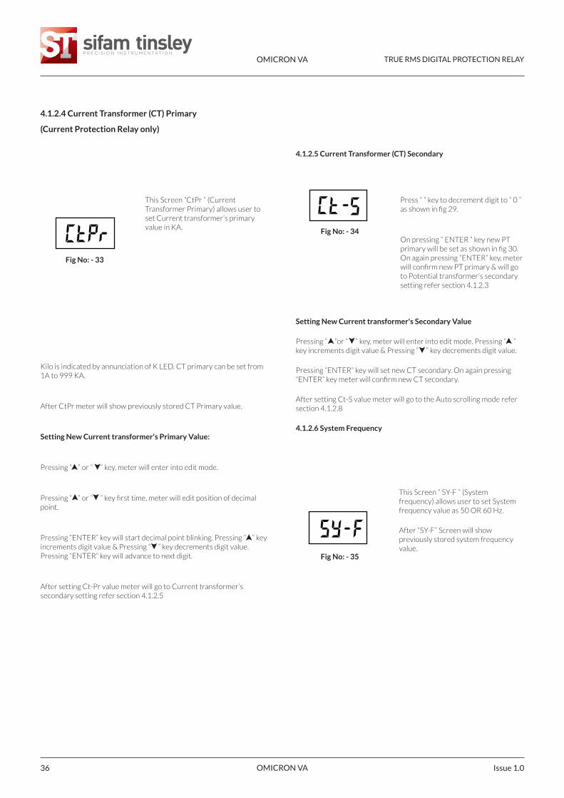
Setting New Potential transformer's Secondary Value:
Pressing “ ” or “ ” key, meter will enter intoedit mode. Pressing “ ” key increments digitvalue & Pressing “ ” key decrements digit value.Pressing “ENTER” key will advance to next digit.After setting Pt-S value meter will go to Systemfrequency setting menu. (Refer Section 4.1.2.6)
This screen allows userto set potential transformer’ssecondary value in V.The PT secondary can be setfrom 100 V to 600 V . L-L L-L
“ Pt-S ” (Potential transformer‘ssecondary) is shown in fig 31“VLL” (Line to Line Voltage) isshown in fig 32. After VLL meterwill show previously stored PTsecondary value. (*Denotesdecimal Point is flashing).
*
OMICRON VA TRUE RMS DIGITAL PROTECTION RELAY
OMICRON VA Issue 1.036
4.1.2.4 Current Transformer (CT) Primary
(Current Protection Relay only)
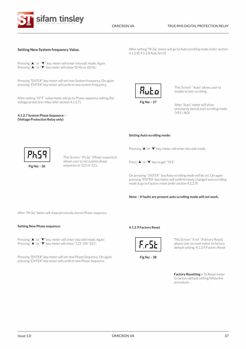
This Screen “CtPr ” (CurrentTransformer Primary) allows user toset Current transformer’s primaryvalue in KA.
Fig No: - 33
Press “ ” key to decrement digit to “ 0 ”as shown in fig 29.
On pressing “ ENTER ” key new PTprimary will be set as shown in fig 30.On again pressing “ENTER” key, meterwill confirm new PT primary & will goto Potential transformer’s secondarysetting refer section 4.1.2.3
Fig No: - 34
Fig No: - 35
4.1.2.5 Current Transformer (CT) Secondary
Setting New Current transformer's Secondary Value
Pressing “ ”or “ ” key, meter will enter into edit mode. Pressing “ ”key increments digit value & Pressing “ ” key decrements digit value.
Pressing “ENTER” key will set new CT secondary. On again pressing“ENTER” key meter will confirm new CT secondary.
After setting Ct-S value meter will go to the Auto scrolling mode refersection 4.1.2.8
4.1.2.6 System Frequency
This Screen “ SY-F ” (Systemfrequency) allows user to set Systemfrequency value as 50 OR 60 Hz.
After “SY-F” Screen will showpreviously stored system frequencyvalue.
Kilo is indicated by annunciation of K LED. CT primary can be set from1A to 999 KA.
After CtPr meter will show previously stored CT Primary value.
Setting New Current transformer's Primary Value:
Pressing “ ” or “ ” key, meter will enter into edit mode.
Pressing “ ” or “ ” key first time, meter will edit position of decimalpoint.
Pressing “ENTER” key will start decimal point blinking. Pressing “ ” keyincrements digit value & Pressing “ ” key decrements digit value.Pressing “ENTER” key will advance to next digit.
After setting Ct-Pr value meter will go to Current transformer’ssecondary setting refer section 4.1.2.5
OMICRON VA TRUE RMS DIGITAL PROTECTION RELAY
OMICRON VA 37Issue 1.0
Setting New System frequency Value.
Pressing “ ” or “ ” key, meter will enter into edit mode. AgainPressing “ ” or “ ” key meter will show 50 Hz or 60 Hz.
Pressing “ENTER” key meter will set new System frequency. On againpressing “ENTER” key meter will confirm new system frequency.
After setting “SY-F” value meter will go to Phase sequence setting (forvoltage protection relay refer section 4.1.2.7).
4.1.2.7 System Phase Sequence: -(Voltage Protection Relay only)
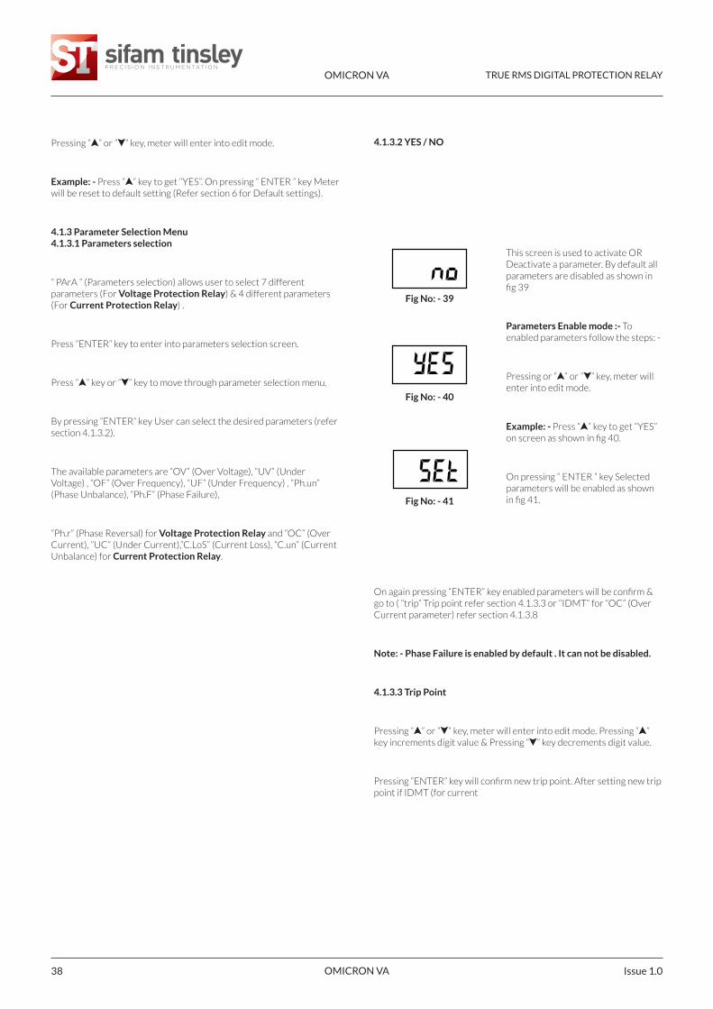
This Screen “ Ph.Sq ” (Phase sequence)allows user to set system phasesequence as 123 or 321.Fig No: - 36
This Screen “ Auto” allows user toenable screen scrolling.
After “Auto” meter will showpreviously stored auto scrolling mode.(YES \ NO)
Fig No: - 37
Fig No: - 38
Setting Auto scrolling mode:
Pressing “ ” or “ ” key, meter will enter into edit mode.
Press “ ” or “ ” key to get “YES”.
On pressing “ ENTER ” key Auto scrolling mode will be set. On againpressing “ENTER” key meter will confirm newly changed auto scrollingmode & go to Factory reset (refer section 4.1.2.9)
Note: - If faults are present auto scrolling mode will not work.
This Screen “ F.rst ” (Factory Reset)allows user to reset meter to factorydefault setting. 4.1.2.9 Factory Reset
Factory Resetting :- To Reset meterto factory default setting follow theprocedure: -
After “Ph.Sq” meter will show previously stored Phase sequence.
Setting New Phase sequence:
Pressing “ ” or “ ” key, meter will enter into edit mode. AgainPressing “ ” or “ ” key meter will show “123” OR “321”.
Pressing “ENTER” key meter will set new Phase Sequence. On againpressing “ENTER” key meter will confirm new Phase Sequence.
After setting “Ph.Sq” meter will go to Auto scrolling mode (refer section4.1.2.8) 4.1.2.8 Auto Scroll
4.1.2.9 Factory Reset
OMICRON VA TRUE RMS DIGITAL PROTECTION RELAY
OMICRON VA Issue 1.038
Pressing “ ” or “ ” key, meter will enter into edit mode.
Example: - Press “ ” key to get “YES”. On pressing “ ENTER ” key Meterwill be reset to default setting (Refer section 6 for Default settings).
4.1.3 Parameter Selection Menu4.1.3.1 Parameters selection
“ PArA ” (Parameters selection) allows user to select 7 differentparameters (For Voltage Protection Relay) & 4 different parameters(For Current Protection Relay) .
Press “ENTER” key to enter into parameters selection screen.
Press “ ” key or “ ” key to move through parameter selection menu.
By pressing “ENTER“ key User can select the desired parameters (refersection 4.1.3.2).
The available parameters are “OV” (Over Voltage), “UV” (UnderVoltage) , “OF” (Over Frequency), “UF” (Under Frequency) , “Ph.un”(Phase Unbalance), “Ph.F” (Phase Failure),
“Ph.r” (Phase Reversal) for Voltage Protection Relay and “OC” (OverCurrent), ”UC” (Under Current),”C.LoS” (Current Loss), “C.un” (CurrentUnbalance) for Current Protection Relay.
This screen is used to activate ORDeactivate a parameter. By default allparameters are disabled as shown infig 39
Parameters Enable mode :- Toenabled parameters follow the steps: -
Pressing or “ ” or “ ” key, meter willenter into edit mode.
Example: - Press “ ” key to get “YES”on screen as shown in fig 40.
On pressing “ ENTER ” key Selectedparameters will be enabled as shownin fig 41.
Fig No: - 39
Fig No: - 40
Fig No: - 41
On again pressing “ENTER” key enabled parameters will be confirm &go to ( “trip” Trip point refer section 4.1.3.3 or “IDMT” for “OC” (OverCurrent parameter) refer section 4.1.3.8
Note: - Phase Failure is enabled by default . It can not be disabled.
4.1.3.3 Trip Point
Pressing “ ” or “ ” key, meter will enter into edit mode. Pressing “ ”key increments digit value & Pressing “ ” key decrements digit value.
Pressing “ENTER” key will confirm new trip point. After setting new trippoint if IDMT (for current
4.1.3.2 YES / NO
OMICRON VA TRUE RMS DIGITAL PROTECTION RELAY
OMICRON VA 39Issue 1.0
protection relay) is enabled meter will goto TMS setting refer section4.1.3.9.1 & if IDMT is disabled meter will go to Trip delay (refer section4.1.3.4)
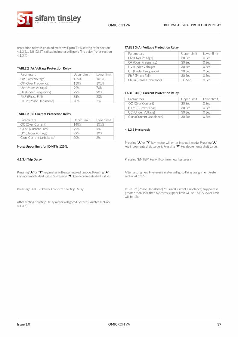
TABLE 2 (A): Voltage Protection Relay
Parameters Upper Limit Lower limit
OV (Over Voltage) 125% 101%
OF (Over Frequency) 110% 101%
UV (Under Voltage) 99% 70%
UF (Under Frequency) 99% 90%
Ph.F (Phase Fail) 85% 20%
Ph.un (Phase Unbalance) 20% 2%
TABLE 2 (B): Current Protection Relay
Parameters Upper Limit Lower limit
OC (Over Current) 140% 101%
C.LoS (Current Loss) 99% 5%
UC (Under Voltage) 99% 10%
C.un (Current Unbalance) 20% 2%
Note: Upper limit for IDMT is 125%.
4.1.3.4 Trip Delay
Pressing “ ” or “ ” key, meter will enter into edit mode. Pressing “ ”key increments digit value & Pressing “ ” key decrements digit value.
Pressing “ENTER” key will confirm new trip Delay.
After setting new trip Delay meter will goto Hysteresis (refer section4.1.3.5)
TABLE 3 (A): Voltage Protection Relay
Parameters Upper Limit Lower limit
OV (Over Voltage) 30 Sec 0 Sec
OF (Over Frequency) 30 Sec 0 Sec
UV (Under Voltage) 30 Sec 0 Sec
UF (Under Frequency) 30 Sec 0 Sec
Ph.F (Phase Fail) 30 Sec 0 Sec
Ph.un (Phase Unbalance) 30 Sec 0 Sec
TABLE 3 (B): Current Protection Relay
Parameters Upper Limit Lower limit
OC (Over Current) 30 Sec 0 Sec
C.LoS (Current Loss) 30 Sec 0 Sec
UC (Under Voltage) 30 Sec 0 Sec
C.un (Current Unbalance) 30 Sec 0 Sec
4.1.3.5 Hysteresis
Pressing “ ” or “ ” key, meter will enter into edit mode. Pressing “ ”key increments digit value & Pressing “ ” key decrements digit value.
Pressing “ENTER” key will confirm new hysteresis.
After setting new Hysteresis meter will goto Relay assignment (refersection 4.1.3.6)
If “Ph.un” (Phase Unbalance) / “C.un” (Current Unbalance) trip point isgreater than 15% then hysteresis upper limit will be 15% & lower limitwill be 1%.
OMICRON VA TRUE RMS DIGITAL PROTECTION RELAY
OMICRON VA Issue 1.040
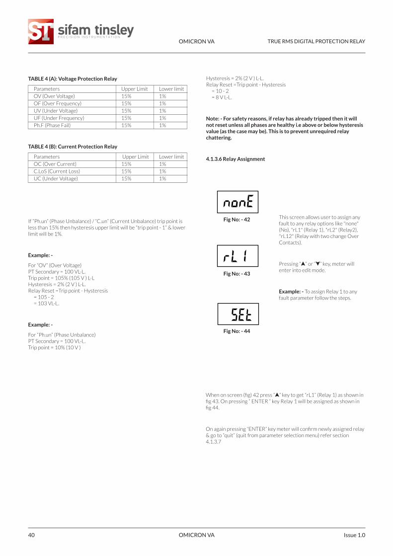
TABLE 4 (A): Voltage Protection Relay
Parameters Upper Limit Lower limit
OV (Over Voltage) 15% 1%
OF (Over Frequency) 15% 1%
UV (Under Voltage) 15% 1%
UF (Under Frequency) 15% 1%
Ph.F (Phase Fail) 15% 1%
TABLE 4 (B): Current Protection Relay
Parameters Upper Limit Lower limit
OC (Over Current) 15% 1%
C.LoS (Current Loss) 15% 1%
UC (Under Voltage) 15% 1%
If “Ph.un” (Phase Unbalance) / “C.un” (Current Unbalance) trip point isless than 15% then hysteresis upper limit will be “trip point - 1” & lowerlimit will be 1%.
Example: -
For “OV” (Over Voltage)PT Secondary = 100 VL-L.Trip point = 105% (105 V ) L-LHysteresis = 2% (2 V ) L-L.Relay Reset =Trip point - Hysteresis
= 105 - 2= 103 VL-L.
Example: -
For “Ph.un” (Phase Unbalance)PT Secondary = 100 VL-L.Trip point = 10% (10 V )
Hysteresis = 2% (2 V ) L-L.Relay Reset =Trip point - Hysteresis
= 10 - 2= 8 V L-L.
Note: - For safety reasons, if relay has already tripped then it willnot reset unless all phases are healthy i.e above or below hysteresisvalue (as the case may be). This is to prevent unrequired relaychattering.
4.1.3.6 Relay Assignment
When on screen (fig) 42 press “ ” key to get “rL1” (Relay 1) as shown infig 43. On pressing “ ENTER ” key Relay 1 will be assigned as shown infig 44.
On again pressing “ENTER” key meter will confirm newly assigned relay& go to “quit” (quit from parameter selection menu) refer section4.1.3.7
This screen allows user to assign anyfault to any relay options like "none"(No), "rL1" (Relay 1), "rL2" (Relay2),"rL12" (Relay with two change OverContacts).
Pressing “ ” or “ ” key, meter willenter into edit mode.
Example: - To assign Relay 1 to anyfault parameter follow the steps.
Fig No: - 42
Fig No: - 43
Fig No: - 44
OMICRON VA TRUE RMS DIGITAL PROTECTION RELAY
OMICRON VA 41Issue 1.0
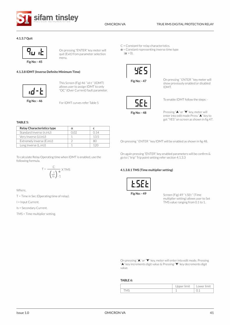
TABLE 5:
Relay Characteristics type α cStandard Inverse (n.inU) 0.02 0.14
Very Inverse (U.inU) 1 13.5
Extremely Inverse (E.inU) 2 80
Long Inverse (L.inU) 1 120
To calculate Relay Operating time when IDMT is enabled, use thefollowing formula.
Where,
T = Time in Sec (Operating time of relay).
I = Input Current.
Is = Secondary Current.
TMS = Time multiplier setting.
C = Constant for relay characteristics.α = Constant representing inverse time type
(α > 0).
On pressing “ ” or “ ” key, meter will enter into edit mode. Pressing “ ” key increments digit value & Pressing “ ” key decrements digitvalue.
TABLE 6:
Upper limit Lower limit
TMS 1 0.1
On pressing “ ENTER ” key meter willshow previously enabled or disabledIDMT.
To enable IDMT follow the steps: -
Pressing “ ” or “ ” key, meter willenter into edit mode Press “ ” key toget “YES” on screen as shown in fig 47.
Fig No: - 47
Fig No: - 48
Fig No: - 49
On pressing “ENTER” key meter willquit (Exit) from parameter selectionmenu.
Fig No: - 45
Fig No: - 46
4.1.3.7 Quit
4.1.3.8 IDMT (Inverse Definite Minimum Time)
This Screen (Fig) 46 “ id-t ” (IDMT)allows user to assign IDMT to only“OC” (Over Current) fault parameter.
For IDMT curves refer Table 5
X TMS
On pressing “ ENTER ” key IDMT will be enabled as shown in fig 48.
On again pressing “ENTER” key enabled parameters will be confirm &go to ( “trip” Trip point setting refer section 4.1.3.3
4.1.3.8.1 TMS (Time multiplier setting)
Screen (Fig) 49 “ t.SEt ” (Timemultiplier setting) allows user to SetTMS value ranging from 0.1 to 1.
T =C
IIs - 1( )
α
OMICRON VA TRUE RMS DIGITAL PROTECTION RELAY
OMICRON VA Issue 1.042
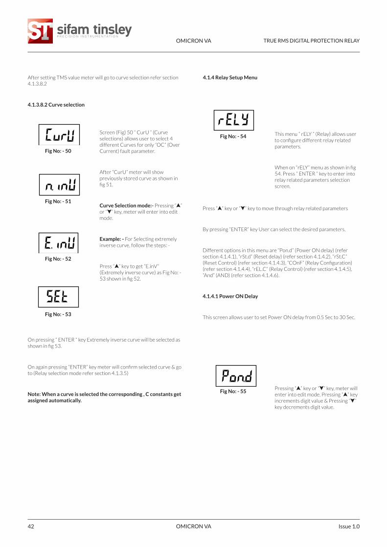
On pressing “ ENTER ” key Extremely inverse curve will be selected asshown in fig 53.
On again pressing “ENTER” key meter will confirm selected curve & goto (Relay selection mode refer section 4.1.3.5)
Note: When a curve is selected the corresponding , C constants getassigned automatically.
4.1.4 Relay Setup Menu
This menu “ rELY ” (Relay) allows userto configure different relay relatedparameters.
When on “rELY” menu as shown in fig54. Press “ ENTER ” key to enter intorelay related parameters selectionscreen.
Fig No: - 54
Fig No: - 55
After setting TMS value meter will go to curve selection refer section4.1.3.8.2
4.1.3.8.2 Curve selection
Fig No: - 50
Screen (Fig) 50 “ CurU ” (Curveselections) allows user to select 4different Curves for only “OC” (OverCurrent) fault parameter.
After “CurU” meter will showpreviously stored curve as shown infig 51.
Curve Selection mode:- Pressing “ ”or “ ” key, meter will enter into editmode.
Example: - For Selecting extremelyinverse curve, follow the steps: -
Press “ ” key to get “E.inV”(Extremely inverse curve) as Fig No: -53 shown in fig 52.
Press “ ” key or “ ” key to move through relay related parameters
By pressing “ENTER“ key User can select the desired parameters.
Different options in this menu are “Pon.d” (Power ON delay) (refersection 4.1.4.1), “rSt.d” (Reset delay) (refer section 4.1.4.2), “rSt.C”(Reset Control) (refer section 4.1.4.3), “COnF” (Relay Configuration)(refer section 4.1.4.4), “rEL.C” (Relay Control) (refer section 4.1.4.5),“And” (AND) (refer section 4.1.4.6).
4.1.4.1 Power ON Delay
This screen allows user to set Power ON delay from 0.5 Sec to 30 Sec.
Pressing “ ” key or “ ” key, meter willenter into edit mode. Pressing “ ” keyincrements digit value & Pressing “ ”key decrements digit value.
Fig No: - 51
Fig No: - 52
Fig No: - 53
OMICRON VA TRUE RMS DIGITAL PROTECTION RELAY
OMICRON VA 43Issue 1.0
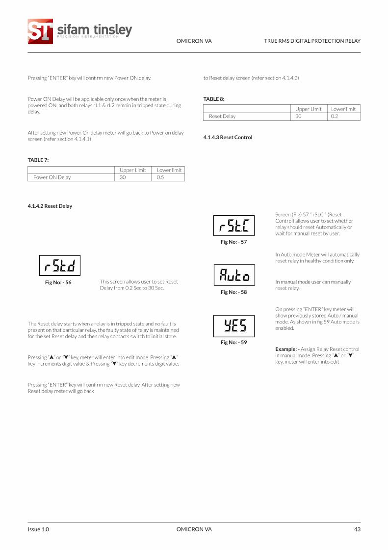
The Reset delay starts when a relay is in tripped state and no fault ispresent on that particular relay, the faulty state of relay is maintainedfor the set Reset delay and then relay contacts switch to initial state.
Pressing “ ” or “ ” key, meter will enter into edit mode. Pressing “ ”key increments digit value & Pressing “ ” key decrements digit value.
Pressing “ENTER” key will confirm new Reset delay. After setting newReset delay meter will go back
to Reset delay screen (refer section 4.1.4.2)
TABLE 8:
Upper Limit Lower limit
Reset Delay 30 0.2
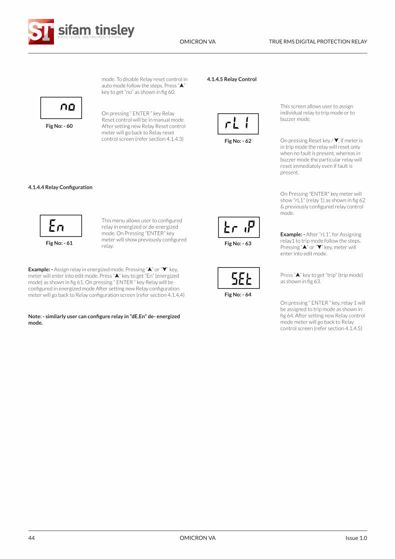
4.1.4.3 Reset Control
Screen (Fig) 57 “ rSt.C ” (ResetControl) allows user to set whetherrelay should reset Automatically orwait for manual reset by user.
In Auto mode Meter will automaticallyreset relay in healthy condition only.
In manual mode user can manuallyreset relay.
On pressing “ENTER” key meter willshow previously stored Auto / manualmode. As shown in fig 59 Auto mode isenabled.
Example: - Assign Relay Reset controlin manual mode. Pressing “ ” or “ ”key, meter will enter into edit
Fig No: - 57
Fig No: - 58
Pressing “ENTER” key will confirm new Power ON delay.
Power ON Delay will be applicable only once when the meter ispowered ON, and both relays rL1 & rL2 remain in tripped state duringdelay.
After setting new Power On delay meter will go back to Power on delayscreen (refer section 4.1.4.1)
TABLE 7:
Upper Limit Lower limit
Power ON Delay 30 0.5
4.1.4.2 Reset Delay
Fig No: - 56 This screen allows user to set ResetDelay from 0.2 Sec to 30 Sec.
Fig No: - 59
OMICRON VA TRUE RMS DIGITAL PROTECTION RELAY
OMICRON VA Issue 1.044
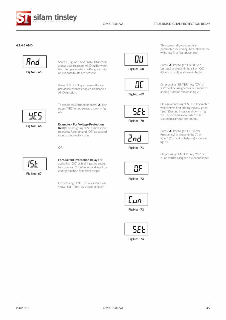
Example: - Assign relay in energized mode. Pressing “ ” or “ ” key,meter will enter into edit mode. Press “ ” key to get “En” (energizedmode) as shown in fig 61. On pressing “ ENTER ” key Relay will beconfigured in energized mode After setting new Relay configurationmeter will go back to Relay configuration screen (refer section 4.1.4.4)
Note: - similarly user can configure relay in “dE.En” de- energizedmode.
4.1.4.5 Relay Control
This screen allows user to assignindividual relay to trip mode or tobuzzer mode.
On pressing Reset key / , if meter isin trip mode the relay will reset onlywhen no fault is present, whereas inbuzzer mode the particular relay willreset immediately even if fault ispresent.
On Pressing "ENTER" key meter willshow "rL1" (relay 1) as shown in fig 62& previously configured relay controlmode.
Example: - After “rL1”, for Assigningrelay1 to trip mode follow the steps.Pressing “ ” or “ ” key, meter willenter into edit mode.
Press “ ” key to get “trip” (trip mode)as shown in fig 63.
On pressing “ ENTER ” key, relay 1 willbe assigned to trip mode as shown infig 64. After setting new Relay controlmode meter will go back to Relaycontrol screen (refer section 4.1.4.5)
Fig No: - 62
Fig No: - 63
Fig No: - 60
mode. To disable Relay reset control inauto mode follow the steps. Press “ ”key to get “no” as shown in fig 60.
On pressing “ ENTER ” key RelayReset control will be in manual mode.After setting new Relay Reset controlmeter will go back to Relay resetcontrol screen (refer section 4.1.4.3)
Fig No: - 64
Fig No: - 61
4.1.4.4 Relay Configuration
This menu allows user to configuredrelay in energized or de-energizedmode. On Pressing "ENTER" keymeter will show previously configuredrelay.
OMICRON VA TRUE RMS DIGITAL PROTECTION RELAY
OMICRON VA 45Issue 1.0
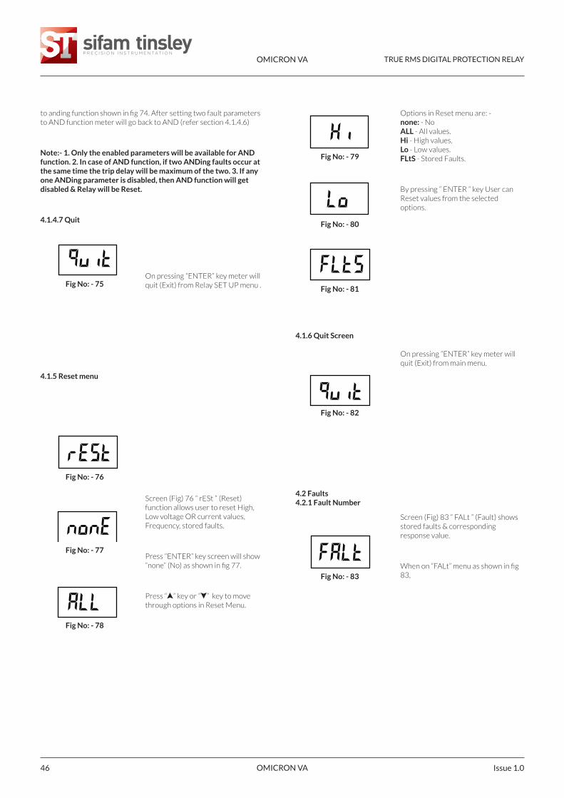
This screen allows to set firstparameter for anding. After this meterwill show first fault parameter
Press “ ” key to get “OV” (OverVoltage) as shown in fig 68 or “OC”(Over current) as shown in fig 69.
On pressing “ ENTER ” key “OV” or“OC” will be assigned as first input toanding function shown in fig 70.
On again pressing “ENTER” key meterwill confirm first anding input & go to“2nd” (Second input) as shown in fig71. This screen allows user to setsecond parameter for anding.
Press “ ” key to get “OF” (OverFrequency) as shown in fig 72 or“C.un” (Current unbalance) shown infig 73.
On pressing “ ENTER ” key “OF” or“C.un”will be assigned as second input
Fig No: - 68
Fig No: - 70
Fig No: - 69
Fig No: - 65
Screen (Fig) 65 “ And ” (AND) functionallows user to assign ANDing betweentwo fault parameters i.e Relay will triponly if both faults are present.
Press “ENTER” key screen will showpreviously stored enabled or disabledAND function.
To enable AND function press “ ” keyto get “YES” on screen as shown in fig66.
Example: - For Voltage ProtectionRelay For assigning “OV” as first inputto anding function and “OF” as secondinput to anding function
OR
For Current Protection Relay Forassigning “OC” as first input to andingfunction and “C.un” as second input toanding function follow the steps: -
On pressing “ ENTER ” key screen willshow “1St” (First) as shown in fig 67.
Fig No: - 71
Fig No: - 72
Fig No: - 73
Fig No: - 74
Fig No: - 66
4.1.4.6 AND
Fig No: - 67
OMICRON VA TRUE RMS DIGITAL PROTECTION RELAY
OMICRON VA Issue 1.046
Options in Reset menu are: -none: - NoALL - All values.Hi - High values.Lo - Low values.FLtS - Stored Faults.
By pressing “ ENTER “ key User canReset values from the selectedoptions.
On pressing “ENTER” key meter willquit (Exit) from main menu.
Screen (Fig) 83 “ FALt ” (Fault) showsstored faults & correspondingresponse value.
When on “FALt” menu as shown in fig83,
Fig No: - 79
Fig No: - 81
Fig No: - 80
Fig No: - 75On pressing “ENTER” key meter willquit (Exit) from Relay SET UP menu .
Screen (Fig) 76 “ rESt ” (Reset)function allows user to reset High,Low voltage OR current values,Frequency, stored faults.
Press “ENTER” key screen will show“none” (No) as shown in fig 77.
Press “ ” key or “ ” key to movethrough options in Reset Menu.
Fig No: - 82
4.1.6 Quit Screen
4.2 Faults4.2.1 Fault Number
Fig No: - 83
Fig No: - 76
to anding function shown in fig 74. After setting two fault parametersto AND function meter will go back to AND (refer section 4.1.4.6)
Note:- 1. Only the enabled parameters will be available for ANDfunction. 2. In case of AND function, if two ANDing faults occur atthe same time the trip delay will be maximum of the two. 3. If anyone ANDing parameter is disabled, then AND function will getdisabled & Relay will be Reset.
4.1.4.7 Quit
Fig No: - 77
Fig No: - 78
4.1.5 Reset menu
OMICRON VA TRUE RMS DIGITAL PROTECTION RELAY
OMICRON VA 47Issue 1.0
Note: - Faults are stored in First InFirst Out (FIFO) order which meansthe latest fault is always stored onfirst location and previous faults getshifted downwards.
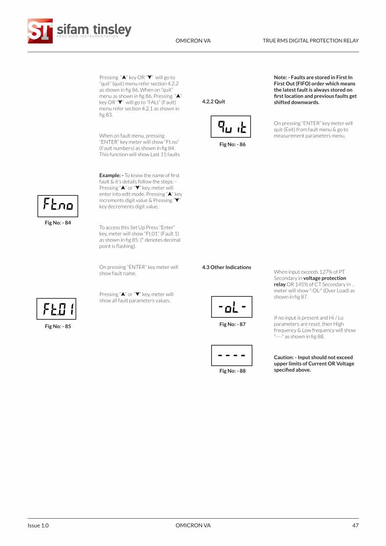
On pressing “ENTER” key meter willquit (Exit) from fault menu & go tomeasurement parameters menu.
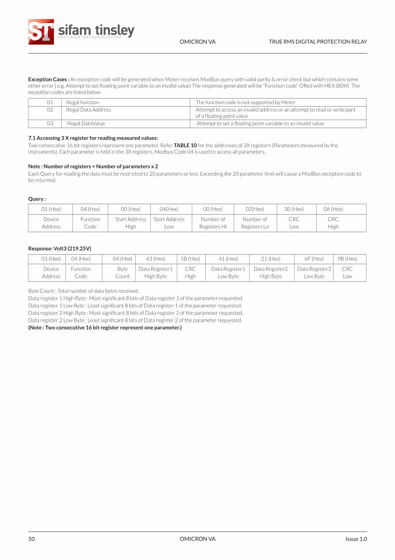
When input exceeds 127% of PTSecondary in voltage protectionrelay OR 145% of CT Secondary in ,meter will show "-OL-" (Over Load) asshown in fig 87.
If no input is present and Hi / Loparameters are reset, then Highfrequency & Low frequency will show"----" as shown in fig 88.
Caution: - Input should not exceedupper limits of Current OR Voltagespecified above.
Fig No: - 86
Fig No: - 88
Fig No: - 87
Fig No: - 84
Pressing “ ” key OR “ ” will go to“quit” (quit) menu refer section 4.2.2as shown in fig 86. When on “quit”menu as shown in fig 86. Pressing “ ”key OR “ ” will go to “FALt” (Fault)menu refer section 4.2.1 as shown infig 83.
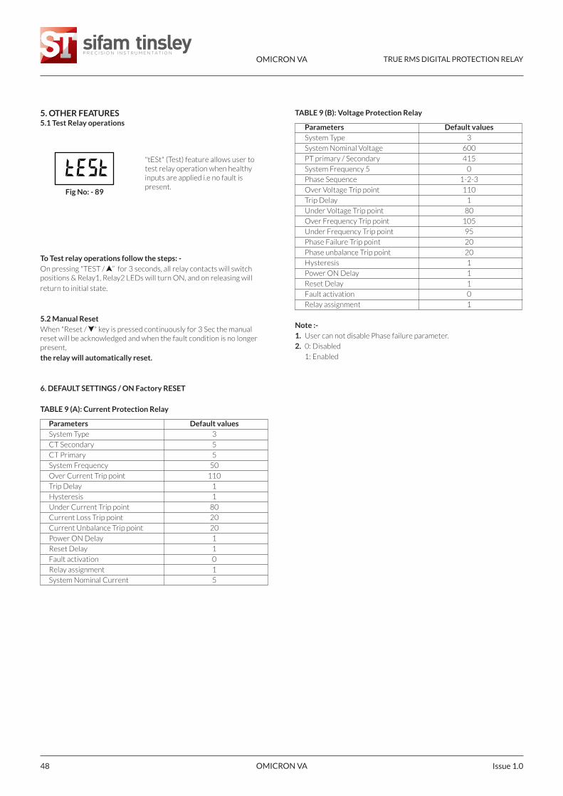
When on fault menu, pressing“ENTER” key meter will show “Ft.no”(Fault numbers) as shown in fig 84.This function will show Last 15 faults
Example: - To know the name of firstfault & it’s details follow the steps: -Pressing “ ” or “ ” key, meter willenter into edit mode. Pressing “ ” keyincrements digit value & Pressing “ ”key decrements digit value.
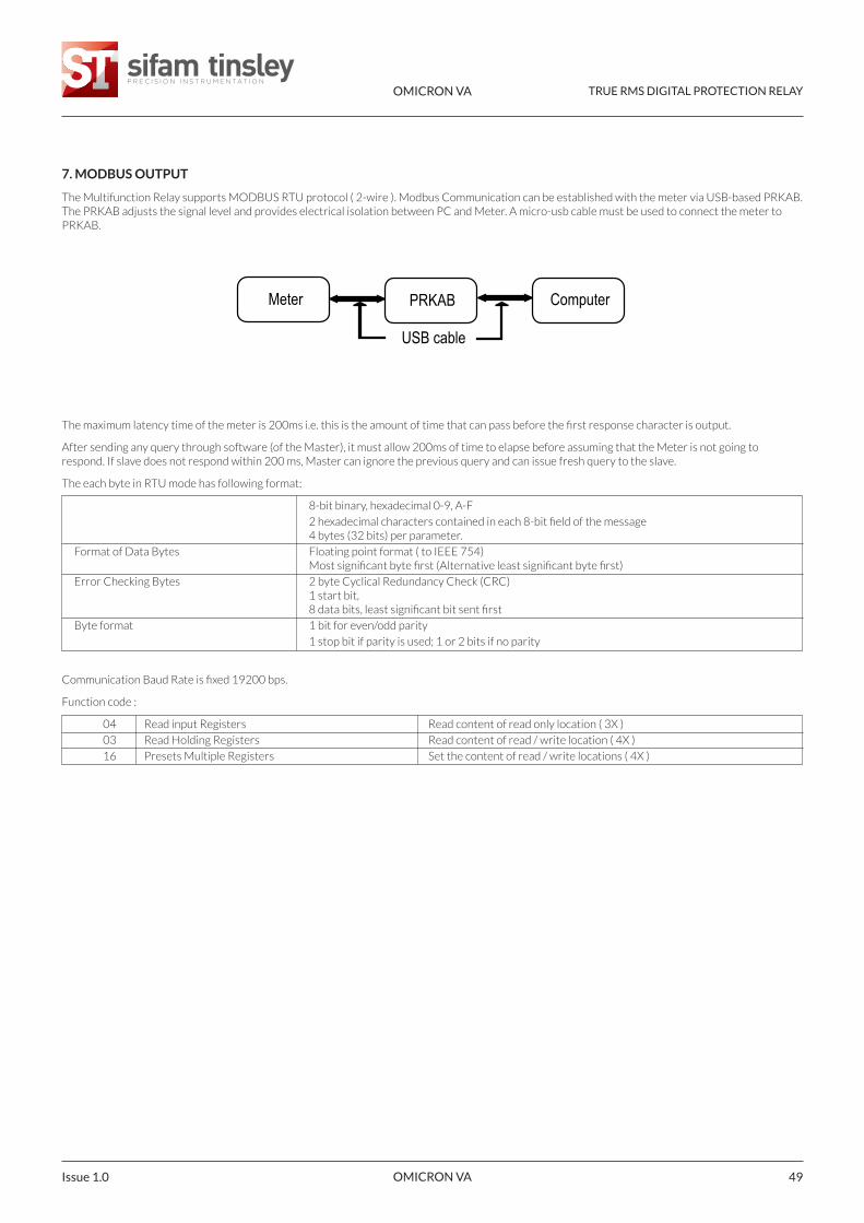
To access this Set Up Press “Enter”key, meter will show “Ft.01” (Fault 1)as shown in fig 85. (* denotes decimalpoint is flashing).
On pressing “ENTER” key meter willshow fault name.
Pressing “ ” or “ ” key, meter willshow all fault parameters values.
4.2.2 Quit
4.3 Other Indications
Fig No: - 85
OMICRON VA TRUE RMS DIGITAL PROTECTION RELAY
OMICRON VA Issue 1.048
"tESt" (Test) feature allows user totest relay operation when healthyinputs are applied i.e no fault ispresent.
5. OTHER FEATURES5.1 Test Relay operations
To Test relay operations follow the steps: -On pressing "TEST / ” for 3 seconds, all relay contacts will switchpositions & Relay1, Relay2 LEDs will turn ON, and on releasing will
return to initial state.
5.2 Manual ResetWhen "Reset / " key is pressed continuously for 3 Sec the manualreset will be acknowledged and when the fault condition is no longerpresent,
the relay will automatically reset.
6. DEFAULT SETTINGS / ON Factory RESET
TABLE 9 (A): Current Protection Relay
Parameters Default valuesSystem Type 3
CT Secondary 5
CT Primary 5
System Frequency 50
Over Current Trip point 110
Trip Delay 1
Hysteresis 1
Under Current Trip point 80
Current Loss Trip point 20
Current Unbalance Trip point 20
Power ON Delay 1
Reset Delay 1
Fault activation 0
Relay assignment 1
System Nominal Current 5
TABLE 9 (B): Voltage Protection Relay
Parameters Default valuesSystem Type 3
System Nominal Voltage 600
PT primary / Secondary 415
System Frequency 5 0
Phase Sequence 1-2-3
Over Voltage Trip point 110
Trip Delay 1
Under Voltage Trip point 80
Over Frequency Trip point 105
Under Frequency Trip point 95
Phase Failure Trip point 20
Phase unbalance Trip point 20
Hysteresis 1
Power ON Delay 1
Reset Delay 1
Fault activation 0
Relay assignment 1
Note :-1. User can not disable Phase failure parameter.
2. 0: Disabled
1: Enabled
Fig No: - 89
OMICRON VA TRUE RMS DIGITAL PROTECTION RELAY
OMICRON VA 49Issue 1.0
7. MODBUS OUTPUT
The Multifunction Relay supports MODBUS RTU protocol ( 2-wire ). Modbus Communication can be established with the meter via USB-based PRKAB.The PRKAB adjusts the signal level and provides electrical isolation between PC and Meter. A micro-usb cable must be used to connect the meter toPRKAB.
The maximum latency time of the meter is 200ms i.e. this is the amount of time that can pass before the first response character is output.
After sending any query through software (of the Master), it must allow 200ms of time to elapse before assuming that the Meter is not going torespond. If slave does not respond within 200 ms, Master can ignore the previous query and can issue fresh query to the slave.
The each byte in RTU mode has following format:
8-bit binary, hexadecimal 0-9, A-F
2 hexadecimal characters contained in each 8-bit field of the message4 bytes (32 bits) per parameter.
Format of Data Bytes Floating point format ( to IEEE 754)Most significant byte first (Alternative least significant byte first)
Error Checking Bytes 2 byte Cyclical Redundancy Check (CRC)1 start bit,8 data bits, least significant bit sent first
Byte format 1 bit for even/odd parity
1 stop bit if parity is used; 1 or 2 bits if no parity
Communication Baud Rate is fixed 19200 bps.
Function code :
04 Read input Registers Read content of read only location ( 3X )
03 Read Holding Registers Read content of read / write location ( 4X )
16 Presets Multiple Registers Set the content of read / write locations ( 4X )
Meter PRKAB Computer
USB cable
OMICRON VA TRUE RMS DIGITAL PROTECTION RELAY
OMICRON VA Issue 1.050
Exception Cases : An exception code will be generated when Meter receives ModBus query with valid parity & error check but which contains someother error ( e.g. Attempt to set floating point variable to an invalid value) The response generated will be “Function code” ORed with HEX (80H). Theexception codes are listed below
01 Illegal function The function code is not supported by Meter
02 Illegal Data Address Attempt to access an invalid address or an attempt to read or write part of a floating point value
03 Illegal DataValue Attempt to set a floating point variable to an invalid value
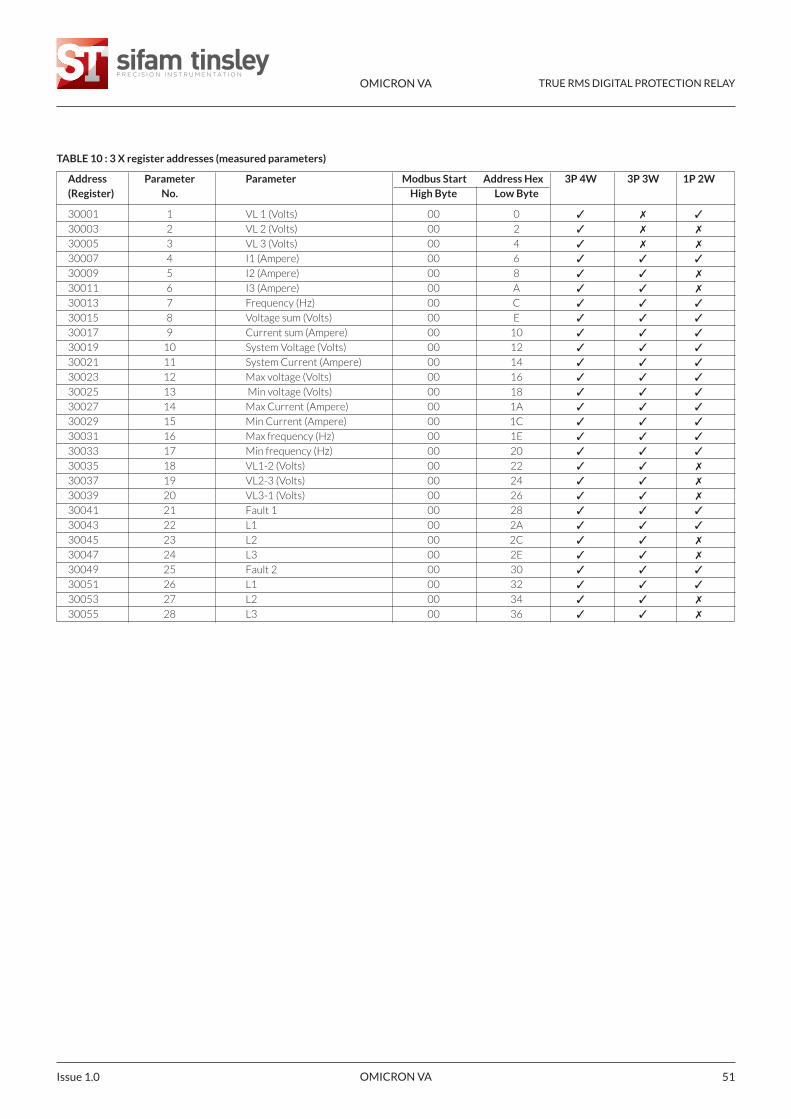
7.1 Accessing 3 X register for reading measured values:Two consecutive 16 bit registers represent one parameter. Refer TABLE 10 for the addresses of 3X registers (Parameters measured by theinstruments). Each parameter is held in the 3X registers. Modbus Code 04 is used to access all parameters.
Note : Number of registers = Number of parameters x 2Each Query for reading the data must be restricted to 20 parameters or less. Exceeding the 20 parameter limit will cause a ModBus exception code tobe returned.
Query :
01 (Hex) 04 (Hex) 00 (Hex) 04(Hex) 00 (Hex) 02(Hex) 30 (Hex) 0A (Hex)
Device Function Start Address Start Address Number of Number of CRC CRC
Address Code High Low Registers Hi Registers Lo Low High
Response: Volt3 (219.25V)
01 (Hex) 04 (Hex) 04 (Hex) 43 (Hex) 5B (Hex) 41 (Hex) 21 (Hex) 6F (Hex) 9B (Hex)
Device Function Byte Data Register1 CRC Data Register1 Data Register2 Data Register2 CRC
Address Code Count High Byte High Low Byte High Byte Low Byte Low
Byte Count : Total number of data bytes received.
Data register 1 High Byte : Most significant 8 bits of Data register 1 of the parameter requested.
Data register 1 Low Byte : Least significant 8 bits of Data register 1 of the parameter requested.
Data register 2 High Byte : Most significant 8 bits of Data register 2 of the parameter requested.
Data register 2 Low Byte : Least significant 8 bits of Data register 2 of the parameter requested.
(Note : Two consecutive 16 bit register represent one parameter.)
OMICRON VA TRUE RMS DIGITAL PROTECTION RELAY
OMICRON VA 51Issue 1.0
TABLE 10 : 3 X register addresses (measured parameters)
Address Parameter Parameter Modbus Start Address Hex 3P 4W 3P 3W 1P 2W(Register) No. High Byte Low Byte
30001 1 VL 1 (Volts) 00 0 ✓ ✗ ✓
30003 2 VL 2 (Volts) 00 2 ✓ ✗ ✗
30005 3 VL 3 (Volts) 00 4 ✓ ✗ ✗
30007 4 I1 (Ampere) 00 6 ✓ ✓ ✓
30009 5 I2 (Ampere) 00 8 ✓ ✓ ✗
30011 6 I3 (Ampere) 00 A ✓ ✓ ✗
30013 7 Frequency (Hz) 00 C ✓ ✓ ✓
30015 8 Voltage sum (Volts) 00 E ✓ ✓ ✓
30017 9 Current sum (Ampere) 00 10 ✓ ✓ ✓
30019 10 System Voltage (Volts) 00 12 ✓ ✓ ✓
30021 11 System Current (Ampere) 00 14 ✓ ✓ ✓
30023 12 Max voltage (Volts) 00 16 ✓ ✓ ✓
30025 13 Min voltage (Volts) 00 18 ✓ ✓ ✓
30027 14 Max Current (Ampere) 00 1A ✓ ✓ ✓
30029 15 Min Current (Ampere) 00 1C ✓ ✓ ✓
30031 16 Max frequency (Hz) 00 1E ✓ ✓ ✓
30033 17 Min frequency (Hz) 00 20 ✓ ✓ ✓
30035 18 VL1-2 (Volts) 00 22 ✓ ✓ ✗
30037 19 VL2-3 (Volts) 00 24 ✓ ✓ ✗
30039 20 VL3-1 (Volts) 00 26 ✓ ✓ ✗
30041 21 Fault 1 00 28 ✓ ✓ ✓
30043 22 L1 00 2A ✓ ✓ ✓
30045 23 L2 00 2C ✓ ✓ ✗
30047 24 L3 00 2E ✓ ✓ ✗
30049 25 Fault 2 00 30 ✓ ✓ ✓
30051 26 L1 00 32 ✓ ✓ ✓
30053 27 L2 00 34 ✓ ✓ ✗
30055 28 L3 00 36 ✓ ✓ ✗
OMICRON VA TRUE RMS DIGITAL PROTECTION RELAY
OMICRON VA Issue 1.052
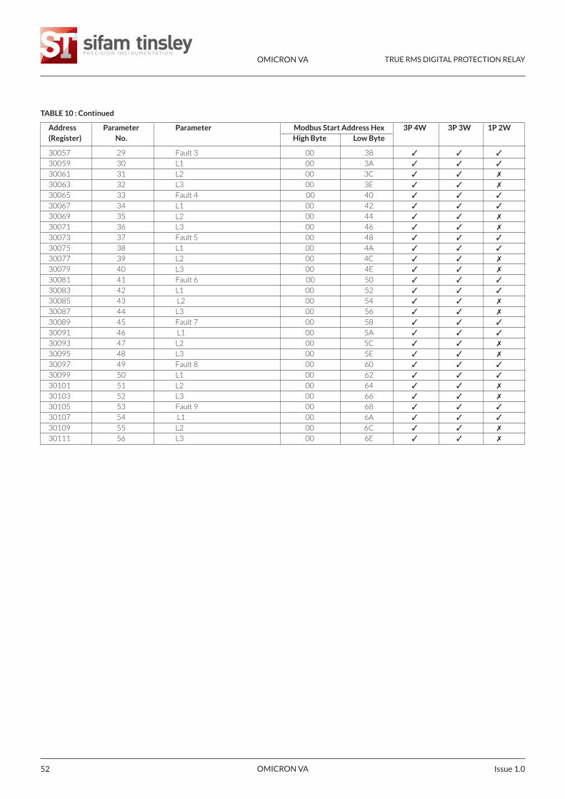
TABLE 10 : Continued
Address Parameter Parameter Modbus Start Address Hex 3P 4W 3P 3W 1P 2W(Register) No. High Byte Low Byte
30057 29 Fault 3 00 38 ✓ ✓ ✓
30059 30 L1 00 3A ✓ ✓ ✓
30061 31 L2 00 3C ✓ ✓ ✗
30063 32 L3 00 3E ✓ ✓ ✗
30065 33 Fault 4 00 40 ✓ ✓ ✓
30067 34 L1 00 42 ✓ ✓ ✓
30069 35 L2 00 44 ✓ ✓ ✗
30071 36 L3 00 46 ✓ ✓ ✗
30073 37 Fault 5 00 48 ✓ ✓ ✓
30075 38 L1 00 4A ✓ ✓ ✓
30077 39 L2 00 4C ✓ ✓ ✗
30079 40 L3 00 4E ✓ ✓ ✗
30081 41 Fault 6 00 50 ✓ ✓ ✓
30083 42 L1 00 52 ✓ ✓ ✓
30085 43 L2 00 54 ✓ ✓ ✗
30087 44 L3 00 56 ✓ ✓ ✗
30089 45 Fault 7 00 58 ✓ ✓ ✓
30091 46 L1 00 5A ✓ ✓ ✓
30093 47 L2 00 5C ✓ ✓ ✗
30095 48 L3 00 5E ✓ ✓ ✗
30097 49 Fault 8 00 60 ✓ ✓ ✓
30099 50 L1 00 62 ✓ ✓ ✓
30101 51 L2 00 64 ✓ ✓ ✗
30103 52 L3 00 66 ✓ ✓ ✗
30105 53 Fault 9 00 68 ✓ ✓ ✓
30107 54 L1 00 6A ✓ ✓ ✓
30109 55 L2 00 6C ✓ ✓ ✗
30111 56 L3 00 6E ✓ ✓ ✗
OMICRON VA TRUE RMS DIGITAL PROTECTION RELAY
OMICRON VA 53Issue 1.0
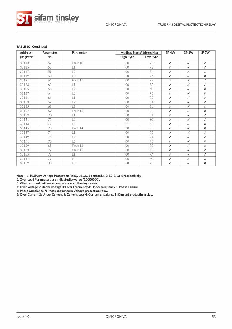
TABLE 10 : Continued
Address Parameter Parameter Modbus Start Address Hex 3P 4W 3P 3W 1P 2W(Register) No. High Byte Low Byte
30113 57 Fault 10 00 70 ✓ ✓ ✓
30115 58 L1 00 72 ✓ ✓ ✓
30117 59 L2 00 74 ✓ ✓ ✗
30119 60 L3 00 76 ✓ ✓ ✗
30121 61 Fault 11 00 78 ✓ ✓ ✓
30123 62 L1 00 7A ✓ ✓ ✓
30125 63 L2 00 7C ✓ ✓ ✗
30127 64 L3 00 7E ✓ ✓ ✗
30131 66 L1 00 82 ✓ ✓ ✓
30133 67 L2 00 84 ✓ ✓ ✓
30135 68 L3 00 86 ✓ ✓ ✗
30137 69 Fault 13 00 88 ✓ ✓ ✗
30139 70 L1 00 8A ✓ ✓ ✓
30141 71 L2 00 8C ✓ ✓ ✓
30143 72 L3 00 8E ✓ ✓ ✗
30145 73 Fault 14 00 90 ✓ ✓ ✗
30147 74 L1 00 92 ✓ ✓ ✓
30149 75 L2 00 94 ✓ ✓ ✓
30151 76 L3 00 96 ✓ ✓ ✗
30129 65 Fault 12 00 80 ✓ ✓ ✗
30153 77 Fault 15 00 98 ✓ ✓ ✓
30155 78 L1 00 9A ✓ ✓ ✓
30157 79 L2 00 9C ✓ ✓ ✗
30159 80 L3 00 9E ✓ ✓ ✗
Note: - 1. In 3P3W Voltage Protection Relay, L1,L2,L3 denote L1-2, L2-3, L3-1 respectively.2. Over Load Parameters are indicated by value "10000000".3. When any fault will occur, meter shows following values.1: Over voltage 2: Under voltage 3: Over Frequency 4: Under frequency 5: Phase Failure6: Phase Unbalance 7: Phase sequence in Voltage protection relay.1: Over Current 2: Under Current 3: Current Loss 4: Current unbalance in Current protection relay.
OMICRON VA TRUE RMS DIGITAL PROTECTION RELAY
OMICRON VA Issue 1.054
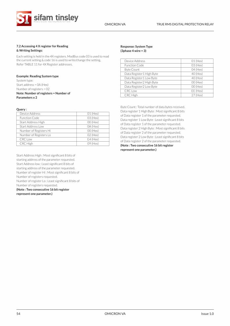
7.2 Accessing 4 X register for Reading& Writing Settings:
Each setting is held in the 4X registers. ModBus code 03 is used to readthe current setting & code 16 is used to write/change the setting.
Refer TABLE 11 for 4X Register addresses.
Example: Reading System typeSystem type:
Start address = 0A (Hex)
Number of registers = 02
Note: Number of registers = Number ofParameters x 2
Query :Device Address 01 (Hex)
Function Code 03 (Hex)
Start Address High 00 (Hex)
Start Address Low 0A (Hex)
Number of Registers Hi 00 (Hex)
Number of Registers Lo 02 (Hex)
CRC Low E4 (Hex)
CRC High 09 (Hex)
Start Address High : Most significant 8 bits of
starting address of the parameter requested.
Start Address low : Least significant 8 bits of
starting address of the parameter requested.
Number of register Hi : Most significant 8 bits of
Number of registers requested.
Number of register Lo : Least significant 8 bits of
Number of registers requested.
(Note : Two consecutive 16 bit registerrepresent one parameter.)
Response: System Type(3phase 4 wire = 3)
Device Address 01 (Hex)
Function Code 03 (Hex)
Byte Count 04 (Hex)
Data Register1 High Byte 40 (Hex)
Data Register1 Low Byte 40 (Hex)
Data Register2 High Byte 00 (Hex)
Data Register2 Low Byte 00 (Hex)
CRC Low EE (Hex)
CRC High 27 (Hex)
Byte Count : Total number of data bytes received.
Data register 1 High Byte : Most significant 8 bits
of Data register 1 of the parameter requested.
Data register 1 Low Byte : Least significant 8 bits
of Data register 1 of the parameter requested.
Data register 2 High Byte : Most significant 8 bits
of Data register 2 of the parameter requested.
Data register 2 Low Byte : Least significant 8 bits
of Data register 2 of the parameter requested.
(Note : Two consecutive 16 bit registerrepresent one parameter.)
OMICRON VA TRUE RMS DIGITAL PROTECTION RELAY
OMICRON VA 55Issue 1.0
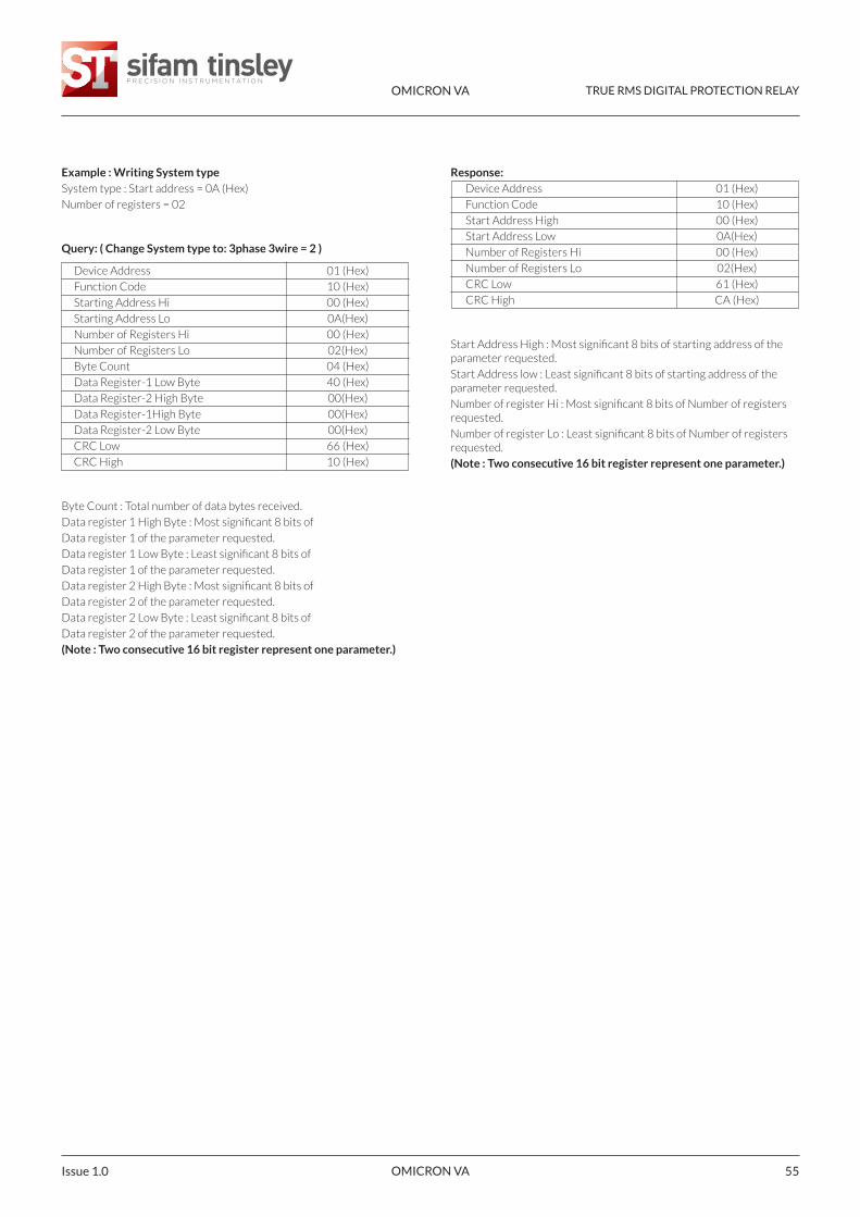
Example : Writing System typeSystem type : Start address = 0A (Hex)
Number of registers = 02
Query: ( Change System type to: 3phase 3wire = 2 )
Device Address 01 (Hex)
Function Code 10 (Hex)
Starting Address Hi 00 (Hex)
Starting Address Lo 0A(Hex)
Number of Registers Hi 00 (Hex)
Number of Registers Lo 02(Hex)
Byte Count 04 (Hex)
Data Register-1 Low Byte 40 (Hex)
Data Register-2 High Byte 00(Hex)
Data Register-1High Byte 00(Hex)
Data Register-2 Low Byte 00(Hex)
CRC Low 66 (Hex)
CRC High 10 (Hex)
Byte Count : Total number of data bytes received.
Data register 1 High Byte : Most significant 8 bits of
Data register 1 of the parameter requested.
Data register 1 Low Byte : Least significant 8 bits of
Data register 1 of the parameter requested.
Data register 2 High Byte : Most significant 8 bits of
Data register 2 of the parameter requested.
Data register 2 Low Byte : Least significant 8 bits of
Data register 2 of the parameter requested.
(Note : Two consecutive 16 bit register represent one parameter.)
Response: Device Address 01 (Hex)
Function Code 10 (Hex)
Start Address High 00 (Hex)
Start Address Low 0A(Hex)
Number of Registers Hi 00 (Hex)
Number of Registers Lo 02(Hex)
CRC Low 61 (Hex)
CRC High CA (Hex)
Start Address High : Most significant 8 bits of starting address of theparameter requested.
Start Address low : Least significant 8 bits of starting address of theparameter requested.
Number of register Hi : Most significant 8 bits of Number of registersrequested.
Number of register Lo : Least significant 8 bits of Number of registersrequested.
(Note : Two consecutive 16 bit register represent one parameter.)
OMICRON VA TRUE RMS DIGITAL PROTECTION RELAY
OMICRON VA Issue 1.056
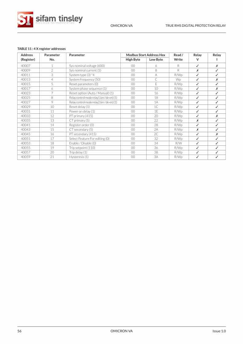
TABLE 11 : 4 X register addresses
Address Parameter Parameter Modbus Start Address Hex Read / Relay Relay(Register) No. High Byte Low Byte Write V I
40007 1 Sys nominal voltage (600) 00 6 R ✓ ✗
40009 2 Sys nominal current (5) 00 8 R ✗ ✓
40011 3 System type (3) *4 00 A R/Wp ✓ ✓
40013 4 System frequency (50) 00 C Wp ✓ ✗
40015 5 Reset parameters (0) 00 E R/Wp ✓ ✓
40017 6 System phase sequence (1) 00 10 R/Wp ✓ ✗
40023 7 Reset option (Auto / Manual) (1) 00 16 R/Wp ✓ ✓
40025 8 Relay control mode relay1 (en / de-en) (1) 00 18 R/Wp ✓ ✓
40027 9 Relay control mode relay2 (en / de-en) (1) 00 1A R/Wp ✓ ✓
40029 10 Reset delay (1) 00 1C R/Wp ✓ ✓
40031 11 Power on delay (1) 00 1E R/Wp ✓ ✓
40033 12 PT primary (415) 00 20 R/Wp ✓ ✗
40035 13 CT primary (5) 00 22 R/Wp ✗ ✓
40041 14 Register order (0) 00 28 R/Wp ✓ ✓
40043 15 CT secondary (5) 00 2A R/Wp ✗ ✓
40045 16 PT secondary (415) 00 2C R/Wp ✓ ✗
40051 17 Select Feature For editing (0) 00 32 R/Wp ✓ ✓
40053 18 Enable / Disable (0) 00 34 R/W ✓ ✓
40055 19 Trip setpoint (110) 00 36 R/Wp ✓ ✓
40057 20 Trip delay (1) 00 38 R/Wp ✓ ✓
40059 21 Hysteresis (1) 00 3A R/Wp ✓ ✓
OMICRON VA TRUE RMS DIGITAL PROTECTION RELAY
OMICRON VA 57Issue 1.0
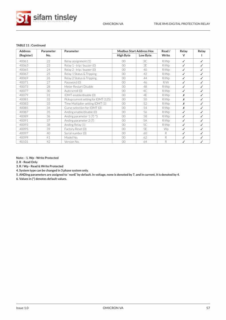
TABLE 11 : Continued
Address Parameter Parameter Modbus Start Address Hex Read / Relay Relay(Register) No. High Byte Low Byte Write V I
40061 22 Relay assignment (1) 00 3C R/Wp ✓ ✓
40063 23 Relay 1 - trip / buzzer (0) 00 3E R/Wp ✓ ✓
40065 24 Relay 2 - trip / buzzer (0) 00 40 R/Wp ✓ ✓
40067 25 Relay 1 Status & Tripping 00 42 R/Wp ✓ ✓
40069 26 Relay 2 Status & Tripping 00 44 R/Wp ✓ ✓
40071 27 Password (0) 00 46 R/W ✓ ✓
40073 28 Meter Restart Disable 00 48 R/Wp ✓ ✓
40077 30 Auto scroll (0) 00 4C R/Wp ✓ ✓
40079 31 IDMT enable/disable (0) 00 4E R/Wp ✗ ✓
40081 32 Pickup current setting for IDMT (125) 00 50 R/Wp ✗ ✓
40083 33 Time Multiplier setting IDMT (1) 00 52 R/Wp ✗ ✓
40085 34 Curve selection for IDMT (0) 00 54 R/Wp ✗ ✓
40087 35 Anding enable/disable (0) 00 56 R/Wp ✓ ✓
40089 36 Anding parameter 1 (7) *5 00 58 R/Wp ✓ ✓
40091 37 Anding parameter 2 (7) 00 5A R/Wp ✓ ✓
40093 38 Anding Relay (1) 00 5C R/Wp ✓ ✓
40095 39 Factory Reset (0) 00 5E Wp ✓ ✓
40097 40 Serial number (0) 00 60 R ✓ ✓
40099 41 Model No. 00 62 R ✓ ✓
40101 42 Version No. 00 64 R ✓ ✓
Note: - 1. Wp - Write Protected2. R - Read Only3. R / Wp - Read & Write Protected4. System type can be changed in 3 phase system only.5. ANDing parameters are assigned to ‘ nonE‘ by default. In voltage, none is denoted by 7, and in current, it is denoted by 4.6. Values in (*) denotes default values.
OMICRON VA TRUE RMS DIGITAL PROTECTION RELAY
OMICRON VA Issue 1.058
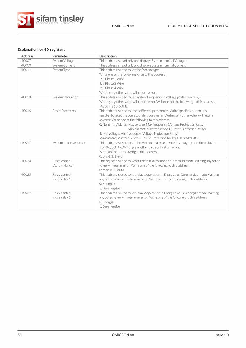
Explanation for 4 X register :
Address Parameter Description40007 System Voltage This address is read only and displays System nominal Voltage
40009 System Current This address is read only and displays System nominal Current
40011 System Type This address is used to set the System type.
Write one of the following value to this address.
1: 1 Phase 2 Wire
2: 3 Phase 3 Wire
3: 3 Phase 4 Wire.
Writing any other value will return error .
40013 System frequency This address is used to set System Frequency in voltage protection relay.
Writing any other value will return error. Write one of the following to this address.
50: 50 Hz 60: 60 Hz
40015 Reset Paramters This address is used to reset different parameters. Write specific value to this
register to reset the corresponding parameter. Writing any other value will return
an error. Write one of the following to this address.
0: None 1: ALL 2: Max voltage, Max frequency (Voltage Protection Relay)
Max current, Max frequency (Current Protection Relay)
3: Min voltage, Min frequency (Voltage Protection Relay)
Min current, Min frequency (Current Protection Relay) 4: stored faults
40017 System Phase sequence This address is used to set the System Phase sequence in voltage protection relay in
3 ph 3w, 3ph 4w. Writing any other value will return error.
Write one of the following to this address.
0: 3-2-1 1: 1-2-3
40023 Reset option This register is used to Reset relays in auto mode or in manual mode. Writing any other
(Auto / Manual) value will return error. Write one of the following to this address.
0: Manual 1: Auto
40025 Relay control This address is used to set relay 1 operation in Energize or De-energize mode. Writing
mode relay 1 any other value will return an error. Write one of the following to this address.
0: Energize
1: De-energize
40027 Relay control This address is used to set relay 2 operation in Energize or De-energize mode. Writing
mode relay 2 any other value will return an error. Write one of the following to this address.
0: Energize
1: De-energize
OMICRON VA TRUE RMS DIGITAL PROTECTION RELAY
OMICRON VA 59Issue 1.0
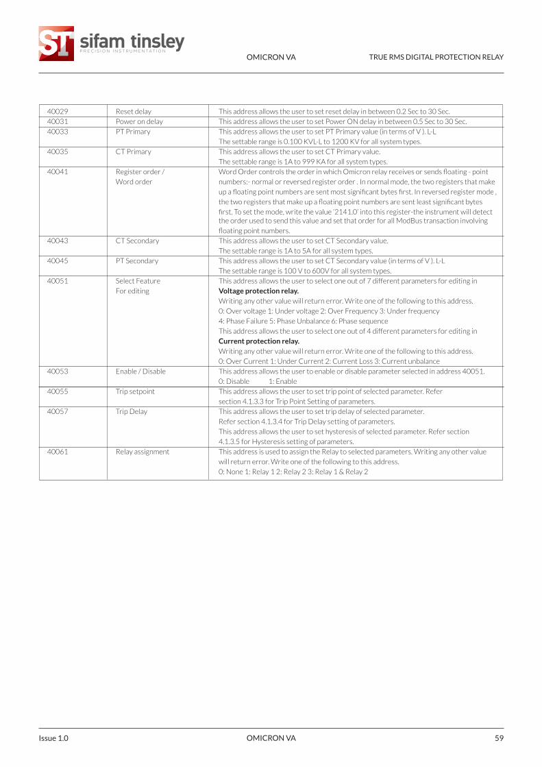
40029 Reset delay This address allows the user to set reset delay in between 0.2 Sec to 30 Sec.
40031 Power on delay This address allows the user to set Power ON delay in between 0.5 Sec to 30 Sec.
40033 PT Primary This address allows the user to set PT Primary value (in terms of V ). L-L
The settable range is 0.100 KVL-L to 1200 KV for all system types.
40035 CT Primary This address allows the user to set CT Primary value.
The settable range is 1A to 999 KA for all system types.
40041 Register order / Word Order controls the order in which Omicron relay receives or sends floating - point
Word order numbers:- normal or reversed register order . In normal mode, the two registers that make
up a floating point numbers are sent most significant bytes first. In reversed register mode ,
the two registers that make up a floating point numbers are sent least significant bytes
first. To set the mode, write the value ‘2141.0’ into this register-the instrument will detect the order used to send this value and set that order for all ModBus transaction involving
floating point numbers.
40043 CT Secondary This address allows the user to set CT Secondary value.
The settable range is 1A to 5A for all system types.
40045 PT Secondary This address allows the user to set CT Secondary value (in terms of V ). L-L
The settable range is 100 V to 600V for all system types.
40051 Select Feature This address allows the user to select one out of 7 different parameters for editing in
For editing Voltage protection relay.Writing any other value will return error. Write one of the following to this address.
0: Over voltage 1: Under voltage 2: Over Frequency 3: Under frequency
4: Phase Failure 5: Phase Unbalance 6: Phase sequence
This address allows the user to select one out of 4 different parameters for editing in
Current protection relay.Writing any other value will return error. Write one of the following to this address.
0: Over Current 1: Under Current 2: Current Loss 3: Current unbalance
40053 Enable / Disable This address allows the user to enable or disable parameter selected in address 40051.
0: Disable 1: Enable
40055 Trip setpoint This address allows the user to set trip point of selected parameter. Refer
section 4.1.3.3 for Trip Point Setting of parameters.
40057 Trip Delay This address allows the user to set trip delay of selected parameter.
Refer section 4.1.3.4 for Trip Delay setting of parameters.
This address allows the user to set hysteresis of selected parameter. Refer section
4.1.3.5 for Hysteresis setting of parameters.
40061 Relay assignment This address is used to assign the Relay to selected parameters. Writing any other value
will return error. Write one of the following to this address.
0: None 1: Relay 1 2: Relay 2 3: Relay 1 & Relay 2
OMICRON VA TRUE RMS DIGITAL PROTECTION RELAY
OMICRON VA Issue 1.060
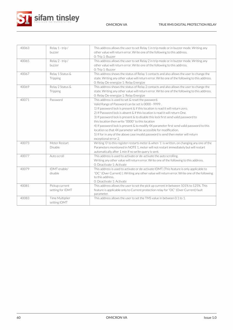
40063 Relay 1 - trip / This address allows the user to set Relay 1 in trip mode or in buzzer mode. Writing any
buzzer other value will return error. Write one of the following to this address.
0: Trip 1: Buzzer
40065 Relay 2 - trip / This address allows the user to set Relay 2 in trip mode or in buzzer mode. Writing any
buzzer other value will return error. Write one of the following to this address.
0: Trip 1: Buzzer
40067 Relay 1 Status & This address shows the status of Relay 1 contacts and also allows the user to change the
Tripping state. Writing any other value will return error. Write one of the following to this address.
0: Relay De-energize 1: Relay Energize
40069 Relay 2 Status & This address shows the status of Relay 2 contacts and also allows the user to change the
Tripping state. Writing any other value will return error. Write one of the following to this address.
0: Relay De-energize 1: Relay Energize
40071 Password This address is used to set & reset the password.
Valid Range of Password can be set is 0000 - 9999 .
1) If password lock is present & if this location is read it will return zero.
2) If Password lock is absent & if this location is read it will return One.
3) If password lock is present & to disable this lock first send valid password to
this location then write “0000” to this location
4) If password lock is present & to modify 4X parameter first send valid password to this
location so that 4X parameter will be accessible for modification.
5) If for in any of the above case invalid password is send then meter will return
exceptional error 2.
40073 Meter Restart Writing ‘0' to this register restarts meter & when ‘1’ is written, on changing any one of the
Disable Parameters mentioned in NOTE 1, meter will not restart immediately but will restart
automatically after 1 min if no write query is sent.
40077 Auto scroll This address is used to activate or de-activate the auto scrolling.
Writing any other value will return error. Write one of the following to this address.
0: Deactivate 1: Activate
40079 IDMT enable/ This address is used to activate or de-activate IDMT. (This feature is only applicable to
disable “OC” (Over Current) ). Writing any other value will return error. Write one of the following to this address.
0: Deactivate 1: Activate
40081 Pickup current This address allows the user to set the pick up current in between 101% to 125%. This
setting for IDMT feature is applicable only to Current protection relay for “OC” (Over Current) fault parameter.
40083 Time Multiplier This address allows the user to set the TMS value in between 0.1 to 1.
setting IDMT
OMICRON VA TRUE RMS DIGITAL PROTECTION RELAY
OMICRON VA 61Issue 1.0
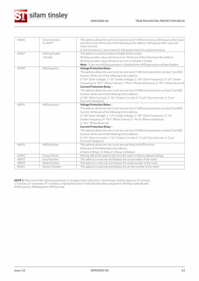
40085 Curve selection This address allows the user to set any one out of 4 different curves. Writing any other value for IDMT will return error. Write one of the following to this address. Writing any other value will
return an error.
0: Normal inverse 1: Very inverse 2: Extremely Inverse 3: Long time Inverse
40087 ANDing Enable This address is used to enable or disable AND function.
/ Disable Writing any other value will return error. Write one of the following to this address.
Writing any other value will return an error. 0: Disable 1: Enable
Note: - if any one ANDing parameter is disabled then ANDing function will get disabled
40089 ANDing para1 Voltage Protection Relay: -This address allows the user to set any one out of 7 different parameters as input 1 to AND
function. Write one of the following to this address.
0: “OV” (Over Voltage), 1: “UV” (Under Voltage), 2: “OF” (Over Frequency), 3: “UF” (Under
Frequency), 4: “Ph.F” (Phase Failure), 5: “Ph.un” (Phase Unbalance), 6: “Ph.r” (Phase Reversal)
Current Protection Relay: -This address allows the user to set any one out of 4 different parameters as input 1 to AND
function. Write one of the following to this address.
0: “OC” (Over Current), 1: “UC” (Under Current), 2: “C.LoS” (Current Loss), 3: “C.un” (Current Unbalance)
40091 ANDing para 2 Voltage Protection Relay: -This address allows the user to set any one out of 7 different parameters as input 2 to AND
function. Write one of the following to this address.
0: “OV” (Over Voltage), 1: “UV” (Under Voltage), 2: “OF” (Over Frequency), 3: “UF”
(Under Frequency), 4: “Ph.F” (Phase Failure), 5: “Ph.un” (Phase Unbalance),
6: “Ph.r” (Phase Reversal)
Current Protection Relay: -This address allows the user to set any one out of 4 different parameters as input 2 to AND
function. Write one of the following to this address.
0: “OC” (Over Current), 1: “UC” (Under Current), 2: “C.LoS” (Current Loss), 3: “C.un” (Current Unbalance)
40093 ANDing Relay This address allows the user to set any one Relay to AND function.
Write one of the following to this address.
0: None 1: Relay 1 2: Relay 2 3: Relay 1 & Relay 2
40095 Factory Reset Writing 100 at this address will reset the meter to factory default settings.
40097 Serial Number This address is read only and displays the serial number of the meter.
40099 Model Number This address is read only and displays the model number of the meter.
40101 Version Number This address is read only and displays the version number of the meter.
NOTE 1: When one of the following parameter is changed, meter will restart : System type, System sequence, PT primary,CT primary, CT secondary, PT secondary, Tripping Parameter Enable/Disable, Relay assignment, ANDing enable/disable,ANDing para1, ANDing para2, ANDing relay.
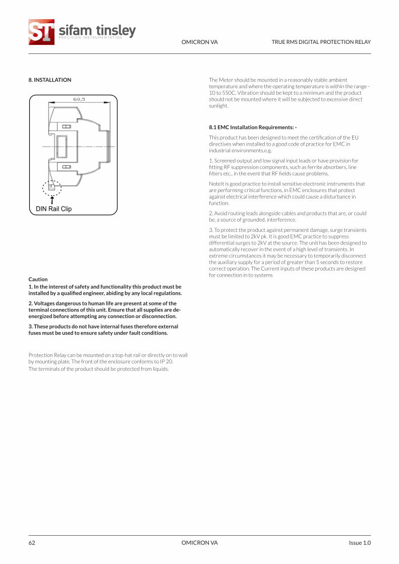
OMICRON VA TRUE RMS DIGITAL PROTECTION RELAY
OMICRON VA Issue 1.062
8. INSTALLATION
Caution1. In the interest of safety and functionality this product must beinstalled by a qualified engineer, abiding by any local regulations.
2. Voltages dangerous to human life are present at some of theterminal connections of this unit. Ensure that all supplies are de-energized before attempting any connection or disconnection.
3. These products do not have internal fuses therefore externalfuses must be used to ensure safety under fault conditions.
Protection Relay can be mounted on a top-hat rail or directly on to wallby mounting plate. The front of the enclosure conforms to IP 20.
The terminals of the product should be protected from liquids.
The Meter should be mounted in a reasonably stable ambienttemperature and where the operating temperature is within the range -10 to 550C. Vibration should be kept to a minimum and the productshould not be mounted where it will be subjected to excessive directsunlight.
8.1 EMC Installation Requirements: -
This product has been designed to meet the certification of the EUdirectives when installed to a good code of practice for EMC inindustrial environments,e.g.
1. Screened output and low signal input leads or have provision forfitting RF suppression components, such as ferrite absorbers, linefilters etc., in the event that RF fields cause problems.
NoteIt is good practice to install sensitive electronic instruments thatare performing critical functions, in EMC enclosures that protectagainst electrical interference which could cause a disturbance infunction.
2. Avoid routing leads alongside cables and products that are, or couldbe, a source of grounded. interference.
3. To protect the product against permanent damage, surge transientsmust be limited to 2kV pk. It is good EMC practice to suppressdifferential surges to 2kV at the source. The unit has been designed toautomatically recover in the event of a high level of transients. Inextreme circumstances it may be necessary to temporarily disconnectthe auxiliary supply for a period of greater than 5 seconds to restorecorrect operation. The Current inputs of these products are designedfor connection in to systems
DIN Rail Clip
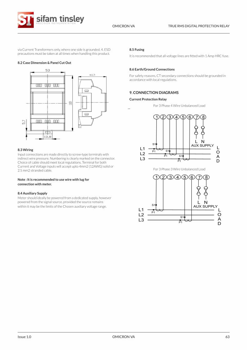
OMICRON VA TRUE RMS DIGITAL PROTECTION RELAY
OMICRON VA 63Issue 1.0
via Current Transformers only, where one side is grounded. 4. ESDprecautions must be taken at all times when handling this product.
8.2 Case Dimension & Panel Cut Out
8.3 WiringInput connections are made directly to screw-type terminals withindirect wire pressure. Numbering is clearly marked on the connector.Choice of cable should meet local regulations. Terminal for bothCurrent and Voltage inputs will accept upto 4mm2 (12AWG) solid or2.5 mm2 stranded cable.
Note : It is recommended to use wire with lug forconnection with meter.
8.4 Auxiliary SupplyMeter should ideally be powered from a dedicated supply, howeverpowered from the signal source, provided the source remains
within it may be the limits of the Chosen auxiliary voltage range.
1 2 3 4 5 6 7 8
L NAUX SUPPLY
L1 L2L3
L OAD
P1
S1
P1
S1
P1
S1
1 2 3 4 5 6 7 8
L NAUX SUPPLY
L1 L2L3
L OADP1
S1
P1
S1
8.5 Fusing
It is recommended that all voltage lines are fitted with 1 Amp HRC fuse.
8.6 Earth/Ground Connections
For safety reasons, CT secondary connections should be grounded inaccordance with local regulations.
9. CONNECTION DIAGRAMS
Current Protection Relay
For 3 Phase 4 Wire Unbalanced Load
For 3 Phase 3 Wire Unbalanced Load
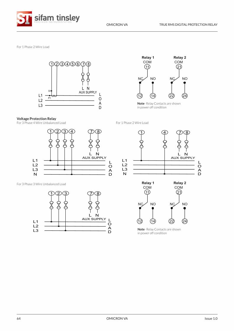
1 2 3 4 5 6 7 8
L NAUX SUPPLY
L1 L2L3
L OAD
P1
S1
1 2 3 7 8
L NAUX SUPPLY
L1 L2L3
L OAD
1 4 7 8
L NAUX SUPPLY
L1 L2L3N
L OAD
Relay 1 Relay 2COM COM11
12 14
NC NO
21
22 24
NC NO
Relay 1 Relay 2COM COM11
12 14
NC NO
21
22 24
NC NO
1 2 3 4 7 8
L NAUX SUPPLY
L1 L2L3N
L OAD
OMICRON VA TRUE RMS DIGITAL PROTECTION RELAY
OMICRON VA Issue 1.064
For 1 Phase 2 Wire Load
Voltage Protection RelayFor 3 Phase 4 Wire Unbalanced Load For 1 Phase 2 Wire Load
For 3 Phase 3 Wire Unbalanced Load
Note- Relay Contacts are shownin power off condition
Note- Relay Contacts are shownin power off condition
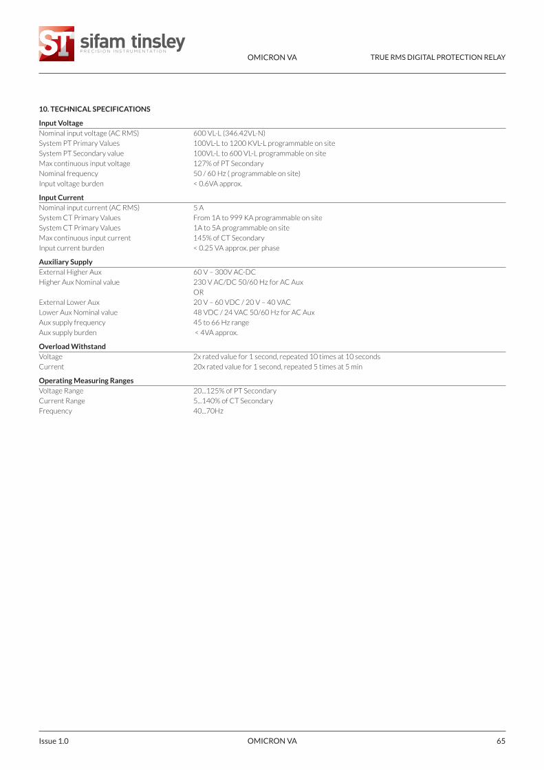
OMICRON VA TRUE RMS DIGITAL PROTECTION RELAY
OMICRON VA 65Issue 1.0
10. TECHNICAL SPECIFICATIONS
Input VoltageNominal input voltage (AC RMS) 600 VL-L (346.42VL-N)
System PT Primary Values 100VL-L to 1200 KVL-L programmable on site
System PT Secondary value 100VL-L to 600 VL-L programmable on site
Max continuous input voltage 127% of PT Secondary
Nominal frequency 50 / 60 Hz ( programmable on site)
Input voltage burden < 0.6VA approx.
Input CurrentNominal input current (AC RMS) 5 A
System CT Primary Values From 1A to 999 KA programmable on site
System CT Primary Values 1A to 5A programmable on site
Max continuous input current 145% of CT Secondary
Input current burden < 0.25 VA approx. per phase
Auxiliary SupplyExternal Higher Aux 60 V – 300V AC-DC
Higher Aux Nominal value 230 V AC/DC 50/60 Hz for AC Aux
OR
External Lower Aux 20 V – 60 VDC / 20 V – 40 VAC
Lower Aux Nominal value 48 VDC / 24 VAC 50/60 Hz for AC Aux
Aux supply frequency 45 to 66 Hz range
Aux supply burden < 4VA approx.
Overload WithstandVoltage 2x rated value for 1 second, repeated 10 times at 10 seconds
Current 20x rated value for 1 second, repeated 5 times at 5 min
Operating Measuring RangesVoltage Range 20...125% of PT Secondary
Current Range 5...140% of CT Secondary
Frequency 40...70Hz
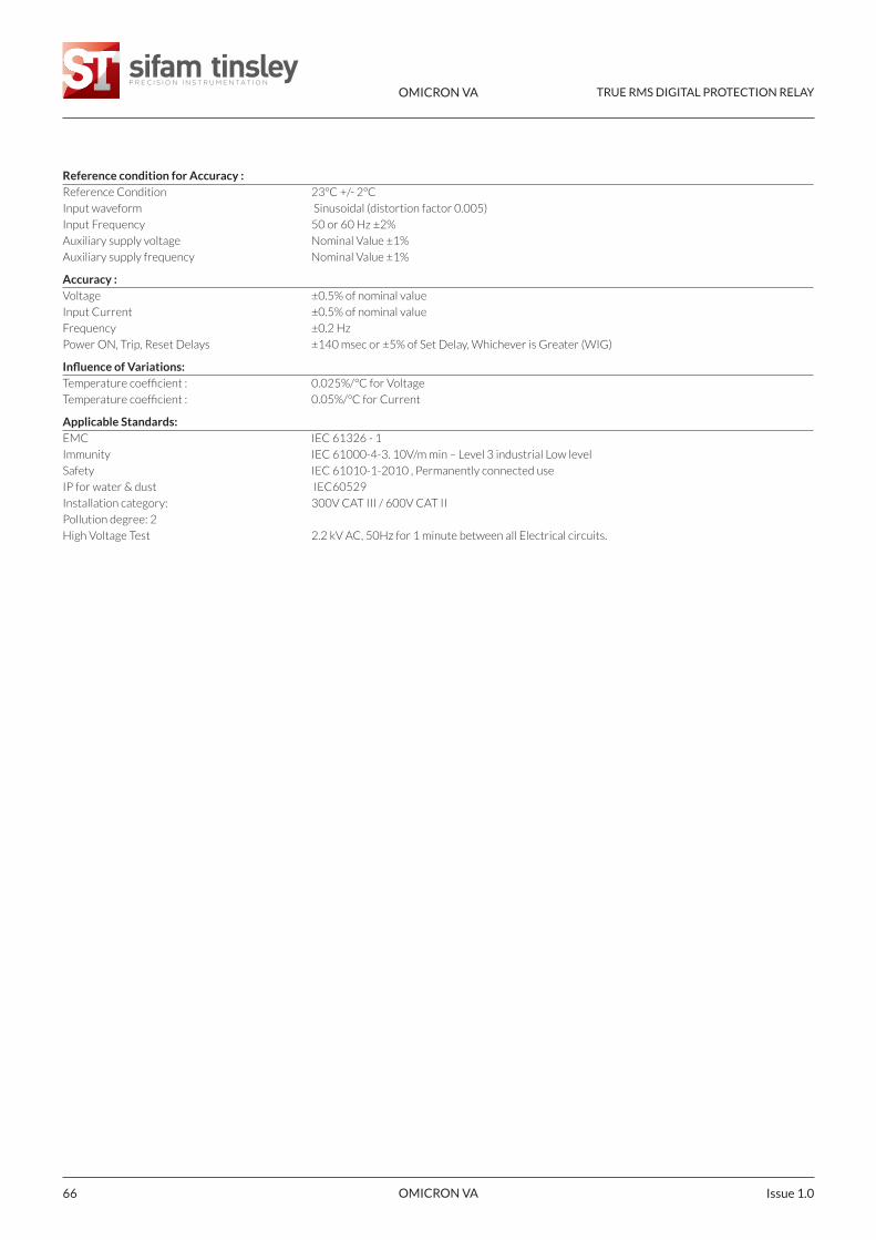
OMICRON VA TRUE RMS DIGITAL PROTECTION RELAY
OMICRON VA Issue 1.066
Reference condition for Accuracy :Reference Condition 23°C +/- 2°C
Input waveform Sinusoidal (distortion factor 0.005)
Input Frequency 50 or 60 Hz ±2%
Auxiliary supply voltage Nominal Value ±1%
Auxiliary supply frequency Nominal Value ±1%
Accuracy :Voltage ±0.5% of nominal value
Input Current ±0.5% of nominal value
Frequency ±0.2 Hz
Power ON, Trip, Reset Delays ±140 msec or ±5% of Set Delay, Whichever is Greater (WIG)
Influence of Variations:Temperature coefficient : 0.025%/°C for Voltage
Temperature coefficient : 0.05%/°C for Current
Applicable Standards:EMC IEC 61326 - 1
Immunity IEC 61000-4-3. 10V/m min – Level 3 industrial Low level
Safety IEC 61010-1-2010 , Permanently connected use
IP for water & dust IEC60529
Installation category: 300V CAT III / 600V CAT II
Pollution degree: 2
High Voltage Test 2.2 kV AC, 50Hz for 1 minute between all Electrical circuits.
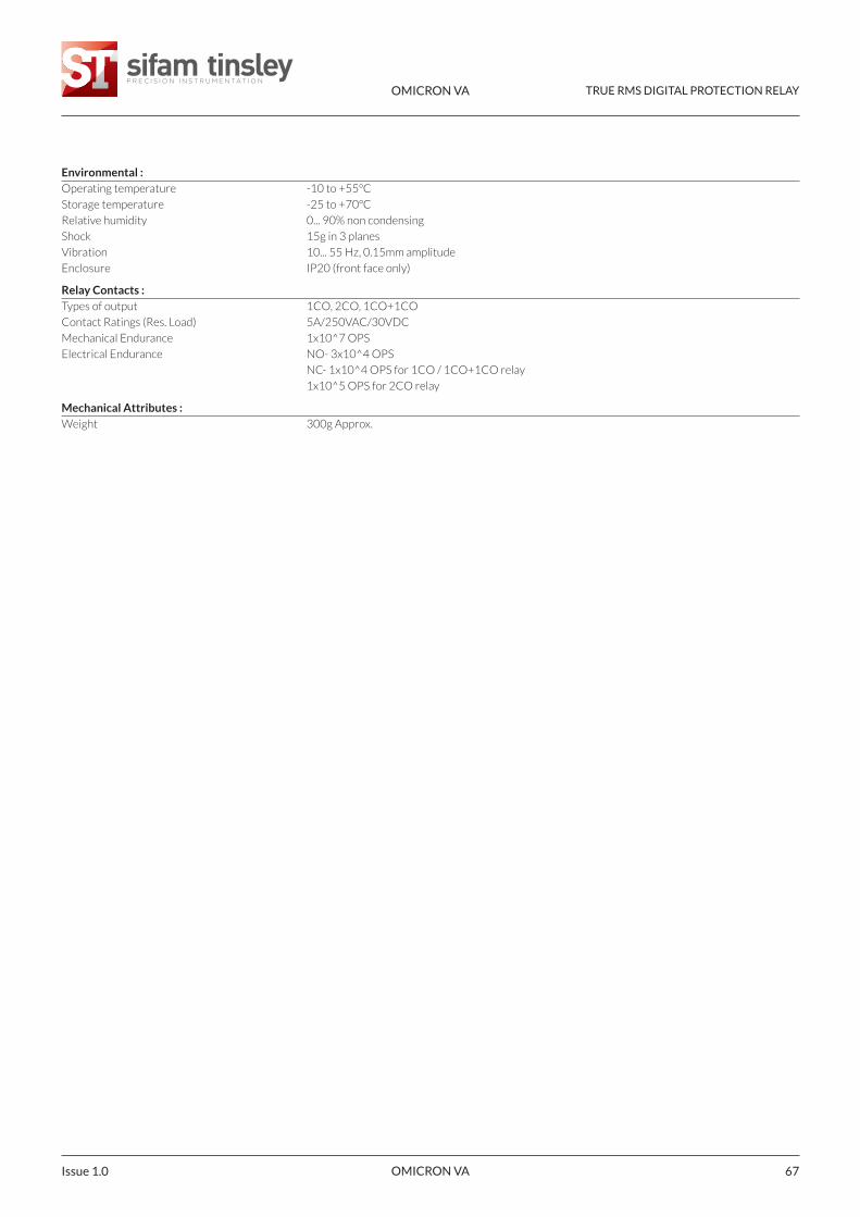
OMICRON VA TRUE RMS DIGITAL PROTECTION RELAY
OMICRON VA 67Issue 1.0
Environmental :Operating temperature -10 to +55°C
Storage temperature -25 to +70°C
Relative humidity 0... 90% non condensing
Shock 15g in 3 planes
Vibration 10... 55 Hz, 0.15mm amplitude
Enclosure IP20 (front face only)
Relay Contacts :Types of output 1CO, 2CO, 1CO+1CO
Contact Ratings (Res. Load) 5A/250VAC/30VDC
Mechanical Endurance 1x10^7 OPS
Electrical Endurance NO- 3x10^4 OPS
NC- 1x10^4 OPS for 1CO / 1CO+1CO relay
1x10^5 OPS for 2CO relay
Mechanical Attributes :Weight 300g Approx.
OMICRON VA TRUE RMS DIGITAL PROTECTION RELAY
OMICRON VA Issue 1.068
The information contained in these installation instructions is for use only by installers trained to make electrical power installations and is intended todescribe the correct method of installation for this product. However, 'manufacturer' has no control over the field conditions which influence productinstallation. It is user's responcibility to determine the suitability of installation method in the user's field condition, 'manufacturer' only obligations areresponcibility to determine suitability of the installation method in the user's field conditions.'Manufacturer' only obligations are those in manufacturerstandard conditions. 'Manufacturer' only obligations are those in 'Manufacturer' standard condition of sale for this product and in no case will'Manufacturer' be liable for any other incidental, indirect or consequential damages arising from the use or misuse of the products.
1 Warner DriveSpringwood Industrial EstateBraintree, EssexCM7 2YW
Tel: 01376 335271E-mail: [email protected]
Sifam Tinsley Instrumentation Ltd
www.sifamtinsley.co.uk
Contact
NOTE: