omicron rev s4 - western.nl manual... · omicron rev s4 he 20 ... oil equalization line and...
TRANSCRIPT
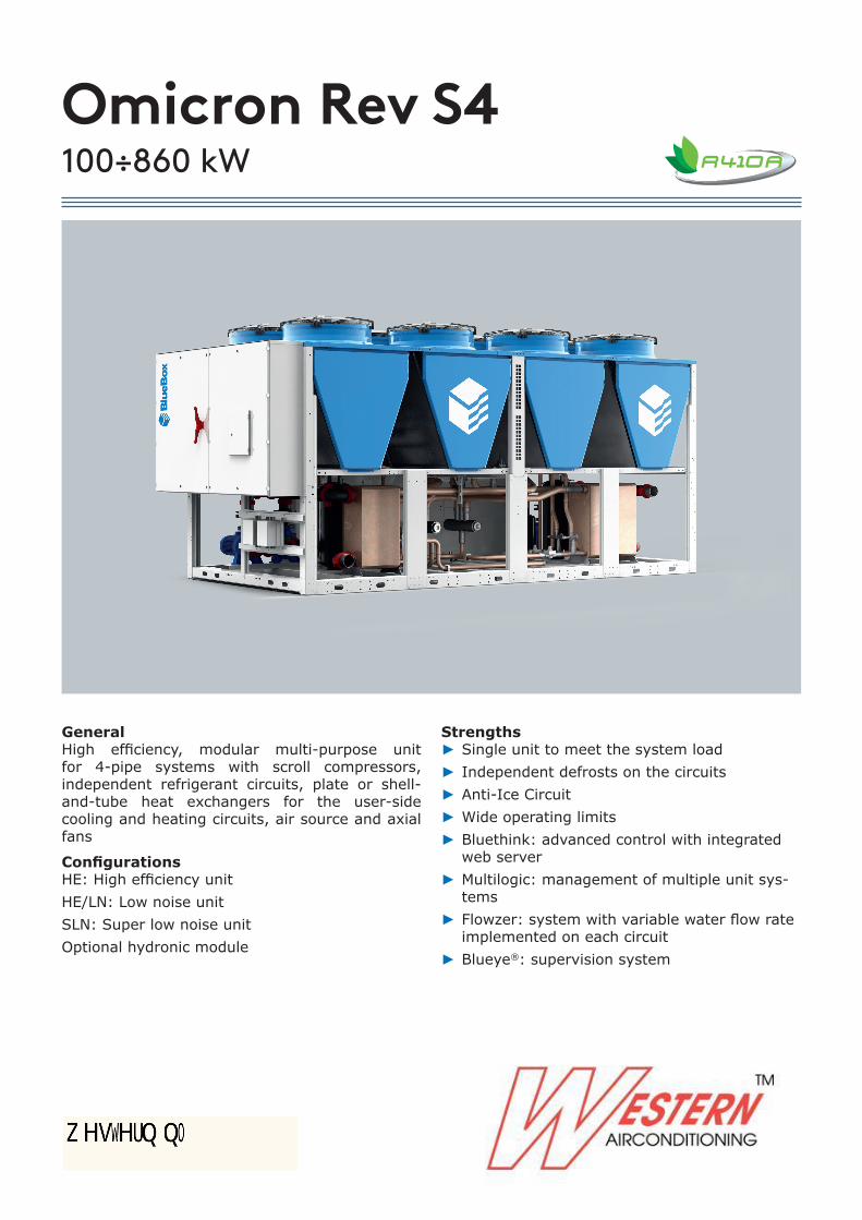
Omicron Rev S4100÷860 kW
GeneralHigh efficiency, modular multi-purpose unit for 4-pipe systems with scroll compressors, independent refrigerant circuits, plate or shell-and-tube heat exchangers for the user-side cooling and heating circuits, air source and axial fans
ConfigurationsHE: High efficiency unitHE/LN: Low noise unitSLN: Super low noise unitOptional hydronic module
Strengths ► Single unit to meet the system load ► Independent defrosts on the circuits ► Anti-Ice Circuit ► Wide operating limits ► Bluethink: advanced control with integrated web server
► Multilogic: management of multiple unit sys-tems
► Flowzer: system with variable water flow rate implemented on each circuit
► Blueye®: supervision system

1
Application and operating principle 3Omicron Rev S4
Product description 4
Description of accessories 8Refrigerant circuit accessories 8Fan accessories 9Hydraulic circuit accessories 10Electrical accessories 14Other accessories 18
Technical specifications 20Omicron Rev S4 HE 20Omicron Rev S4 SLN 22
Electrical specifications 24
Pump data 25
User-side exchanger flow rate fields 26
Operating limits 27
Noise levels 28Omicron Rev S4 HE 28Omicron Rev S4 SLN 29
Installation advice 30Water characteristics 30Glycol mixtures 30Minimum water content in the system 31Installation site 32Installations that require the use of treated coils 33Aeraulic head losses and options available for the ventilating section 34
Dimensional diagrams 36

2
3
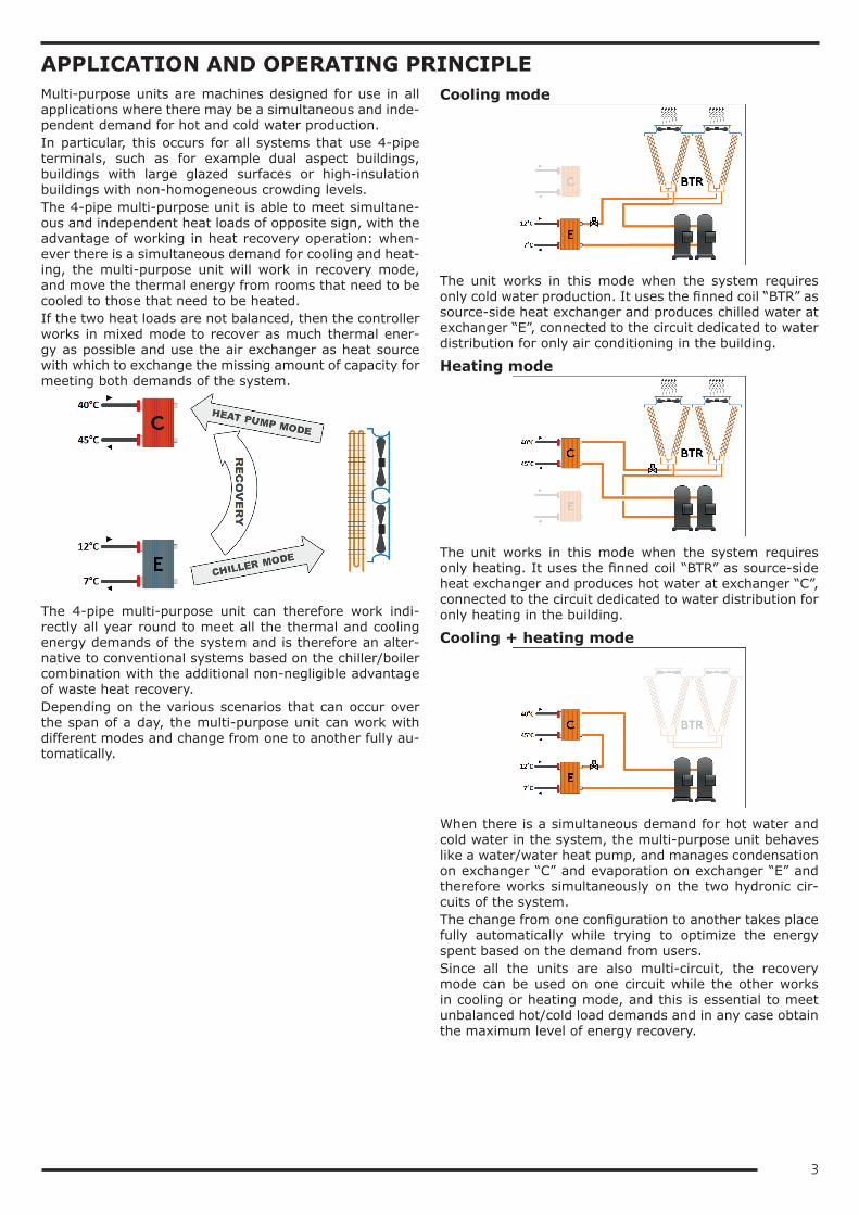
APPLICATION AND OPERATING PRINCIPLEMulti-purpose units are machines designed for use in all applications where there may be a simultaneous and inde-pendent demand for hot and cold water production.In particular, this occurs for all systems that use 4-pipe terminals, such as for example dual aspect buildings, buildings with large glazed surfaces or high-insulation buildings with non-homogeneous crowding levels.The 4-pipe multi-purpose unit is able to meet simultane-ous and independent heat loads of opposite sign, with the advantage of working in heat recovery operation: when-ever there is a simultaneous demand for cooling and heat-ing, the multi-purpose unit will work in recovery mode, and move the thermal energy from rooms that need to be cooled to those that need to be heated.If the two heat loads are not balanced, then the controller works in mixed mode to recover as much thermal ener-gy as possible and use the air exchanger as heat source with which to exchange the missing amount of capacity for meeting both demands of the system.
The 4-pipe multi-purpose unit can therefore work indi-rectly all year round to meet all the thermal and cooling energy demands of the system and is therefore an alter-native to conventional systems based on the chiller/boiler combination with the additional non-negligible advantage of waste heat recovery.Depending on the various scenarios that can occur over the span of a day, the multi-purpose unit can work with different modes and change from one to another fully au-tomatically.
Cooling mode
The unit works in this mode when the system requires only cold water production. It uses the finned coil “BTR” as source-side heat exchanger and produces chilled water at exchanger “E”, connected to the circuit dedicated to water distribution for only air conditioning in the building.
Heating mode
The unit works in this mode when the system requires only heating. It uses the finned coil “BTR” as source-side heat exchanger and produces hot water at exchanger “C”, connected to the circuit dedicated to water distribution for only heating in the building.
Cooling + heating mode
When there is a simultaneous demand for hot water and cold water in the system, the multi-purpose unit behaves like a water/water heat pump, and manages condensation on exchanger “C” and evaporation on exchanger “E” and therefore works simultaneously on the two hydronic cir-cuits of the system.The change from one configuration to another takes place fully automatically while trying to optimize the energy spent based on the demand from users.Since all the units are also multi-circuit, the recovery mode can be used on one circuit while the other works in cooling or heating mode, and this is essential to meet unbalanced hot/cold load demands and in any case obtain the maximum level of energy recovery.
4
Omicron Rev S4High efficiency, modular multi-purpose unit for 4-pipe systems with scroll compressors, independent refrigerant circuits, plate or shell-and-tube heat exchangers for the user-side cooling and heating circuits, air source and axial fans
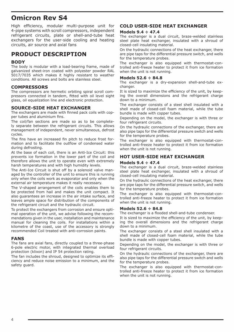
PRODUCT DESCRIPTIONBODYThe body is modular with a load-bearing frame, made of galvanized sheet-iron coated with polyester powder RAL 5017/7035 which makes it highly resistant to weather conditions. All screws and bolts are stainless steel.
COMPRESSORSThe compressors are hermetic orbiting spiral scroll com-pressors connected in tandem, fitted with oil level sight glass, oil equalization line and electronic protection.
SOURCE-SIDE HEAT EXCHANGERThe exchangers are made with finned pack coils with cop-per tubes and aluminium fins.The coil/fan sections are made so as to be complete-ly separate between the refrigerant circuits. This allows management of independent, never simultaneous, defrost cycles.The fins have an increased fin pitch to reduce frost for-mation and to facilitate the outflow of condensed water during defrosting.At the base of each coil, there is an Anti-Ice Circuit: this prevents ice formation in the lower part of the coil and therefore allows the unit to operate even with extremely harsh temperatures and with high humidity levels.The Anti-Ice Circuit is shut off by a solenoid valve man-aged by the controller of the unit to ensure this is running only when the coils work as evaporator and only when the external air temperature makes it really necessary.The V-shaped arrangement of the coils enables them to be protected from hail and makes the unit compact. It also guarantees an increase in the air intake surface, and leaves ample space for distribution of the components of the refrigerant circuit and the hydraulic circuit.To protect the exchangers from corrosion and ensure opti-mal operation of the unit, we advise following the recom-mendations given in the user, installation and maintenance manual for cleaning the coils. For installations within a kilometre of the coast, use of the accessory is strongly recommended Coil treated with anti-corrosion paints.
FANSThe fans are axial fans, directly coupled to a three-phase 6-pole electric motor, with integrated thermal overload protection (klixon) and IP 54 protection rating.The fan includes the shroud, designed to optimize its effi-ciency and reduce noise emission to a minimum, and the safety guard.
COLD USER-SIDE HEAT EXCHANGERModels 9.4 ÷ 47.4The exchanger is a dual circuit, braze-welded stainless steel plate heat exchanger, insulated with a shroud of closed-cell insulating material.On the hydraulic connections of the heat exchanger, there are pipe taps for the differential pressure switch, and wells for the temperature probes.The exchanger is also equipped with thermostat-con-trolled anti-freeze heater to protect it from ice formation when the unit is not running.
Models 52.6 ÷ 84.8The exchanger is a dry-expansion shell-and-tube ex-changer.It is sized to maximize the efficiency of the unit, by keep-ing the overall dimensions and the refrigerant charge down to a minimum.The exchanger consists of a steel shell insulated with a shell made of closed-cell foam material, while the tube bundle is made with copper tubes.Depending on the model, the exchanger is with three or four refrigerant circuits.On the hydraulic connections of the exchanger, there are also pipe taps for the differential pressure switch and wells for the temperature probes.The exchanger is also equipped with thermostat-con-trolled anti-freeze heater to protect it from ice formation when the unit is not running.
HOT USER-SIDE HEAT EXCHANGERModels 9.4 ÷ 47.4The exchanger is a dual circuit, braze-welded stainless steel plate heat exchanger, insulated with a shroud of closed-cell insulating material.On the hydraulic connections of the heat exchanger, there are pipe taps for the differential pressure switch, and wells for the temperature probes.The exchanger is also equipped with thermostat-con-trolled anti-freeze heater to protect it from ice formation when the unit is not running.
Models 52.6 ÷ 84.8The exchanger is a flooded shell-and-tube condenser.It is sized to maximize the efficiency of the unit, by keep-ing the overall dimensions and the refrigerant charge down to a minimum.The exchanger consists of a steel shell insulated with a shell made of closed-cell foam material, while the tube bundle is made with copper tubes.Depending on the model, the exchanger is with three or four refrigerant circuits.On the hydraulic connections of the exchanger, there are also pipe taps for the differential pressure switch and wells for the temperature probes.The exchanger is also equipped with thermostat-con-trolled anti-freeze heater to protect it from ice formation when the unit is not running.
5
REFRIGERANT CIRCUITThe unit uses refrigerant gas R410A.Each refrigerant circuit of the unit comprises:• shut-off valve in the liquid line• 5/16” charging valves• liquid sight glass• replaceable solid cartridge dehydrator filter• two electronic expansion valves per circuit• mechanical thermostatic valve dedicated to defrosting• 4-way reversing valve• suction separator• fluid accumulator• pressure transducers for reading high and low pressure
values• high pressure switches• safety valves• Anti-Ice Circuit with solenoid valveThe pipes of the circuit and the exchanger are insulated with extruded closed-cell expanded elastomer that is re-sistant to UV rays.
ELECTRICAL CONTROL PANELThe electrical control panel is made in a painted galva-nized sheet-iron box with forced ventilation and IP54 pro-tection rating.The electrical control panel of the basic unit comprises:• main disconnect switch• automatic circuit breakers for compressors with fixed
calibration• fuses for protecting the fans and auxiliary circuits• fan contactors• phase-cutting fan speed adjuster• thermal magnetic circuit breakers for pumps (if pres-
ent)• phase monitor• potential-free general alarm contacts• single potential free operating contacts for compres-
sors, fans and pumps (when present)• digital input for general ON/OFF• digital input for cold circuit ON/OFF• digital input for hot circuit ON/OFF• external air temperature probe• microprocessor controller with display accessible from
the outsideAll the electrical cables inside the panel are numbered and the terminal board dedicated to the customer's connec-tions is coloured blue so that it can be quickly identified in the panel.Standard power supply of the unit is 400V/3~/50Hz
CONTROL BLUETHINKMain controller functionsThe microprocessor control allows the following functions:• water temperature control, with control of water at the
outlet on the cold exchanger and on the hot exchanger• freeze protection• compressor timings• automatic rotation of compressor starting sequence• recording of the log of all machine inputs, outputs and
states• automatic rotation of compressor starting sequence• recording of the alarm log• sliding defrost management• sliding defrost management• management of independent, never simultaneous, de-
frosts on the various refrigerant circuits• digital input for general ON/OFF• digital input for cold circuit ON/OFF• digital input for hot circuit ON/OFF• digital input for hot circuit ON/OFF• Ethernet serial port with Modbus protocol and integrat-
ed web server preloaded web pageFor further details on available functions and on displayed information, you can refer to the specific documentation of the control.By default, the serial connections present as standard are enabled only for reading from BMS. Enabling of writing from BMS is to be requested when ordering.
Main functions of the webserverAs standard, the Bluethink controller integrates a web-server with a preloaded web page that is accessed via password.The web page allows the following functions to be carried out (some of these are available only for users with ad-vanced level rights):• display of the main information on the unit, such as
serial n°, size, type of refrigerant• display of the general status of the machine: water inlet
and outlet temperatures, external air temperature, op-erating mode, evaporating and condensing pressures, suction and discharge temperatures
• display of the status of compressors, fans, pumps, elec-tronic expansion valves
• display in real time of the graphs of the main quantities• display of the graphs of logged quantities• display of alarm log• display of the status of all the I/Os of the controller• management of users on several levels• remote ON/OFF• remote set point change• remote time band change• remote summer winter mode selection

6
Human-Machine InterfaceThe control has a graphic display that allows the following information to be displayed:• water inlet and outlet temperature of the cold circuit• water inlet and outlet temperature of the hot circuit• set temperature and differential set points• description of alarms• hour meter of operation and number of start-ups of the
unit, the compressors and the pumps (if present)• high and low pressure values, and relevant condensing
and evaporating temperatures• external air temperature• superheating at compressor suction.
Management of defrost cyclesFor defrost management, the control of the unit uses a sliding intervention threshold, depending on the pressures inside the unit and the external air temperature. By put-ting together all this information, the control can identify the presence of ice on the coil and activates the defrosting sequence only when necessary, so as to maximize the en-ergy efficiency of the unit.Sliding management of the defrost threshold ensures that, as the absolute humidity of outdoor air decreases, the fre-quency of the defrost cycles gradually decreases because they are carried out only when the ice formed on the coil actually penalizes performance.The defrost cycle is fully automatic and is carried out using a patented defrost system (patent n° 1335232): during the initial stage, a defrost is carried out by cycle reversal with fans stopped. When the frost on the coil has melted sufficiently, reverse ventilation is activated, that is, with air flow in the opposite direction to that of normal oper-ation, so as to facilitate the ejection of condensed water and detached ice. When the coil is clean, ventilation is reversed again and the unit resumes operation in heat pump mode.The combination of the sliding intervention threshold and the patented defrost system allows the number and dura-tion of defrost cycles to be optimized and reduced to the minimum.
CONTROLS AND SAFETY DEVICESAll the units are fitted with the following control and safety components:• high pressure switch with manual reset• high pressure safety device with automatic reset, for a
limited number of occurrences, managed by the con-troller
• low pressure safety device with automatic reset and limited tripping managed by the controller
• high pressure safety valves• antifreeze probe at the outlet of the user-side heat ex-
changers• differential pressure switch already fitted on the us-
er-side heat exchangers• overtemperature protection for compressors and fans
TESTINGAll the units are factory-tested and supplied complete with oil and refrigerant.
PACKAGINGThere are yellow lifting brackets at the base of the unit to allow lifting with lifting beam.The unit is wrapped in a protective transparent polyethyl-ene stretch film.
VERSIONSOmicron Rev S4 HEThese units involve the use of exchangers with high ex-change surface area in order to make high efficiency units.
Omicron Rev S4 SLNThese units involve the use of a soundproofed compressor compartment and fans with speed adjuster calibrated with a reduced air flow rate. The speed reduction of the fans is such that, under nominal operating conditions in chill-er mode, the air flow rate and noise level are lower than those of the high efficiency version of the unit.In any case, the use of the speed adjuster to reduce the air flow rate allows rotation of the fans at maximum speed when external air temperature conditions are particularly critical and therefore guarantees the same operating lim-its as the high efficiency versions.In heat pump mode, the fans always operate at 100% speed and therefore guarantee the same performance lev-els as the high efficiency version.
7
OPTIONS/LN: low noise unitIn the unit with /LN option, all the compressors are en-closed in a compartment that is fully soundproofed with sound absorbing material and soundproofing material.
/HAT: unit for high external air temperaturesThe unit fitted with this accessory adopts an electrical con-trol panel made using specific components to withstand high temperatures, special cables and oversize protection parts.The accessory enables the unit to work with external air temperatures of over 46°C as indicated in the section on operating limits.With this accessory, operation is guaranteed with external air temperature up to 50°C.For higher temperatures up to about 55°C, a set-up with air conditioning of the electrical control panel is neces-sary; the unit works in capacity reduction mode. The fea-sibility of this set-up must be assessed: please contact our sales department.
HYDRAULIC MODULESAll units can be fitted with hydraulic module in various configurations:• /1P/1R: hydraulic module with one pump on the cold
circuit and one pump on the hot circuit• /2P/2R: hydraulic module with two pumps on the cold
circuit and two pumps on the hot circuitThe hydraulic modules with one pump per circuit (/1P/1R) have:• one pump on the cooling circuit and one pump on the
heating circuit• a gate valve on the delivery side of each pump• a safety valve on each hydraulic circuit set to 6barThe hydraulic modules with two pumps per circuit (/2P/2R) have:• two pumps on the cooling circuit and two pumps on the
heating circuit• a check valve on the delivery side of each pump• a safety valve on each hydraulic circuit set to 6barIn the version with 2 pumps, these are always with one on standby while the other is working. Switching over be-tween the pumps is automatic and is done by time (to balance the hours of operation of each one) or in the event of failure.
8
DESCRIPTION OF ACCESSORIESRefrigerant circuit accessoriesThe "(S)" symbol indicates that the option is present as standard in the unit, provided this is not in conflict with other selected accessories.
BC Capacitive backup battery for electronic expansion valveWhen the compressors stop, the controller always closes the electronic expansion valve to prevent dangerous refrigerant migration. The presence of the backup battery ensures that the electronic valve is kept in closed position even when there is no power supplyThis accessory uses a condenser, and not an ordinary battery, as energy storage: this allows it to be unaffected by the memory effect of normal batteries and eliminates its need for maintenance.
BK Brine KitThis accessory is compulsory if a water temperature set point lower than +3°C is used (if the unit is provided with double set point or variable set point, the lower set point is considered).The accessory consists of increased insulation and suitable sizing and calibration of some components.The inlet and outlet temperatures of the user-side exchanger must be given on ordering to allow correct set-ting of the alarm parameters and verification of the sizing of the expansion valve.The cooling set point can then be changed by the customer in an interval that, compared to the set point given on ordering, ranges from -1K up to the maximum temperature allowed by the above-stated operating limits.The unit will be optimized to work at the set point temperature given on ordering. For different set points, the cooling capacity provided and the level of efficiency of the machine could decrease and move away from these conditions.
DVS Double safety valveWith this accessory, instead of each individual safety valve per circuit, there is a "candelabrum" with two safety valves and a diverter valve for choosing the valve in operation. This allows the safety valves to be replaced without having to drain the machine and without having to stop it.
MAFR Pressure gaugesThe operating pressures of each circuit of the unit can be displayed on the control by accessing the relevant screens. Also, the machine can be fitted with pressure gauges (two for each circuit) installed in a clearly visible position. These allow reading in real time of the working pressures of the refrigerant gas on the low pressure side and on the high pressure side of each refrigerant circuit.
RG Fan speed adjuster (S)The control manages the speed of the fans through a phase cutting speed governor, in order to optimize the operating conditions and efficiency of the unit.This control also has the effect of reducing the noise level of the unit: in fact, the typical conditions under which the control will be modulating the speed of the fans are those of the night, spring and autumn.For units equipped with EC fans, the same function is carried out using the electronically commutated motor of the fans and is supplied as standard.
RPP Refrigerant leak detector with automatic pump downWith this accessory, a refrigerant leak detector is placed inside each compressor compartment. Detection of a refrigerant leak is managed by the control through a specific alarm and display of a specific icon on the display of the control. For all the circuits of the unit, the alarm also starts the machine stopping procedure with pump down, confining all the refrigerant in the coils.The accessory includes the capacitive backup battery.The accessory can be applied only to units in LN or SLN set-up.
RPR Refrigerant leak detectorWith this accessory, a refrigerant leak detector is placed inside each compressor compartment. Detection of a refrigerant leak is managed by the controller through a specific alarm and display of a specific icon on the display of the controller. This alarm stops the unit.The accessory can be applied only to units in LN or SLN set-up.
RUB Compressor suction and delivery valvesThe valves situated on the delivery side and on the suction side of the compressors allow the compressor to be isolated from the rest of the refrigerant circuit, so making the maintenance operations quicker and less invasive
9
Fan accessoriesVEC EC fans
With this accessory, EC fans, with electronically commutated brushless motor, are used for the ventilating section. These guarantee very high efficiency levels for all working conditions and allow a 15% saving on the power absorbed by each fan working at full capacity.Also, through a 0-10V analogue signal sent to each fan, the microprocessor carries out condensation/evapo-ration control by continuous adjustment of the air flow rate as the external air temperature changes, with a further reduction in electrical absorption and noise emission.
VEM Oversize EC fansWith this accessory, oversize EC fans, with electronically commutated brushless motor, are used for the ven-tilating section. These guarantee very high efficiency levels for all working conditions. Through a 0-10V ana-logue signal sent to each fan, the microprocessor carries out condensation/evaporation control by continuous adjustment of the air flow rate as the external air temperature changes, with a further reduction in electrical absorption and noise emission.Oversize EC fans allow a residual available discharge head of about 100Pa to be obtained.
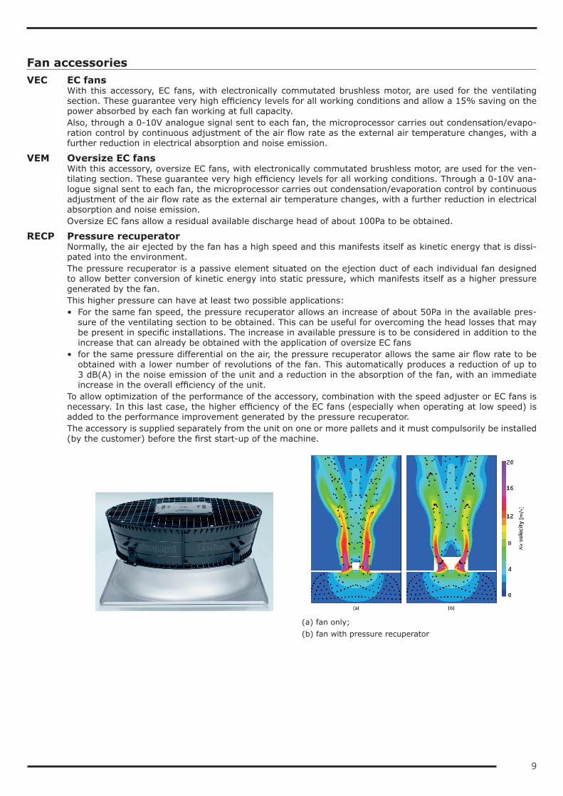
RECP Pressure recuperatorNormally, the air ejected by the fan has a high speed and this manifests itself as kinetic energy that is dissi-pated into the environment.The pressure recuperator is a passive element situated on the ejection duct of each individual fan designed to allow better conversion of kinetic energy into static pressure, which manifests itself as a higher pressure generated by the fan.This higher pressure can have at least two possible applications:• For the same fan speed, the pressure recuperator allows an increase of about 50Pa in the available pres-
sure of the ventilating section to be obtained. This can be useful for overcoming the head losses that may be present in specific installations. The increase in available pressure is to be considered in addition to the increase that can already be obtained with the application of oversize EC fans
• for the same pressure differential on the air, the pressure recuperator allows the same air flow rate to be obtained with a lower number of revolutions of the fan. This automatically produces a reduction of up to 3 dB(A) in the noise emission of the unit and a reduction in the absorption of the fan, with an immediate increase in the overall efficiency of the unit.
To allow optimization of the performance of the accessory, combination with the speed adjuster or EC fans is necessary. In this last case, the higher efficiency of the EC fans (especially when operating at low speed) is added to the performance improvement generated by the pressure recuperator.The accessory is supplied separately from the unit on one or more pallets and it must compulsorily be installed (by the customer) before the first start-up of the machine.
(a) fan only;(b) fan with pressure recuperator
10
Hydraulic circuit accessoriesThe "(S)" symbol indicates that the option is present as standard in the unit, provided this is not in conflict with other selected accessories.
FVPF FLOWZER VP - Inverter for manual pump adjustment cold circuitFVPC FLOWZER VP - Inverter for manual pump adjustment hot circuit
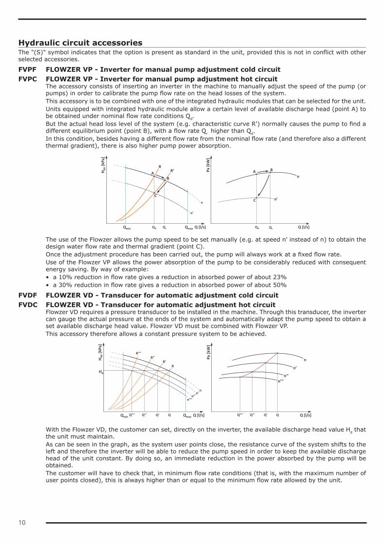
The accessory consists of inserting an inverter in the machine to manually adjust the speed of the pump (or pumps) in order to calibrate the pump flow rate on the head losses of the system.This accessory is to be combined with one of the integrated hydraulic modules that can be selected for the unit.Units equipped with integrated hydraulic module allow a certain level of available discharge head (point A) to be obtained under nominal flow rate conditions Qd.But the actual head loss level of the system (e.g. characteristic curve R') normally causes the pump to find a different equilibrium point (point B), with a flow rate Qr higher than Qd.In this condition, besides having a different flow rate from the nominal flow rate (and therefore also a different thermal gradient), there is also higher pump power absorption.
QrQd Q [l/s]
n’
Qmin
n
Qmax
HAV
[kPa
]
n
n’
Pa [k
W]
Q [l/s]
RR’
Qd Qr
A B
C
AB
C
The use of the Flowzer allows the pump speed to be set manually (e.g. at speed n' instead of n) to obtain the design water flow rate and thermal gradient (point C).Once the adjustment procedure has been carried out, the pump will always work at a fixed flow rate.Use of the Flowzer VP allows the power absorption of the pump to be considerably reduced with consequent energy saving. By way of example:• a 10% reduction in flow rate gives a reduction in absorbed power of about 23%• a 30% reduction in flow rate gives a reduction in absorbed power of about 50%
FVDF FLOWZER VD - Transducer for automatic adjustment cold circuitFVDC FLOWZER VD - Transducer for automatic adjustment hot circuit
Flowzer VD requires a pressure transducer to be installed in the machine. Through this transducer, the inverter can gauge the actual pressure at the ends of the system and automatically adapt the pump speed to obtain a set available discharge head value. Flowzer VD must be combined with Flowzer VP.This accessory therefore allows a constant pressure system to be achieved.
Q [l/s]
R
n’’’n’’
n’
Qmin
n
Qmax
HAV
[kPa
]
Hd
R’R’’
R’’’
Q’’’ Q’’ Q’ Q
Pa [k
W]
Q’’’ Q’’ Q’ Q
n
n’
n’’n’’’
Q [l/s]
With the Flowzer VD, the customer can set, directly on the inverter, the available discharge head value Hd that the unit must maintain.As can be seen in the graph, as the system user points close, the resistance curve of the system shifts to the left and therefore the inverter will be able to reduce the pump speed in order to keep the available discharge head of the unit constant. By doing so, an immediate reduction in the power absorbed by the pump will be obtained.The customer will have to check that, in minimum flow rate conditions (that is, with the maximum number of user points closed), this is always higher than or equal to the minimum flow rate allowed by the unit.
11
This accessory is useful when the total head losses of the circuit are slightly variable or when they change depending on the seasons (for example, some user points are active only during summer operation and not during winter operation).The use of this accessory also allows the pump speed to be adapted to possible fouling of the filter on the hydraulic circuit.
FVFF FLOWZER VFPP – Kit for variable flow rate primary circuit pump with bypass valve included cold circuit
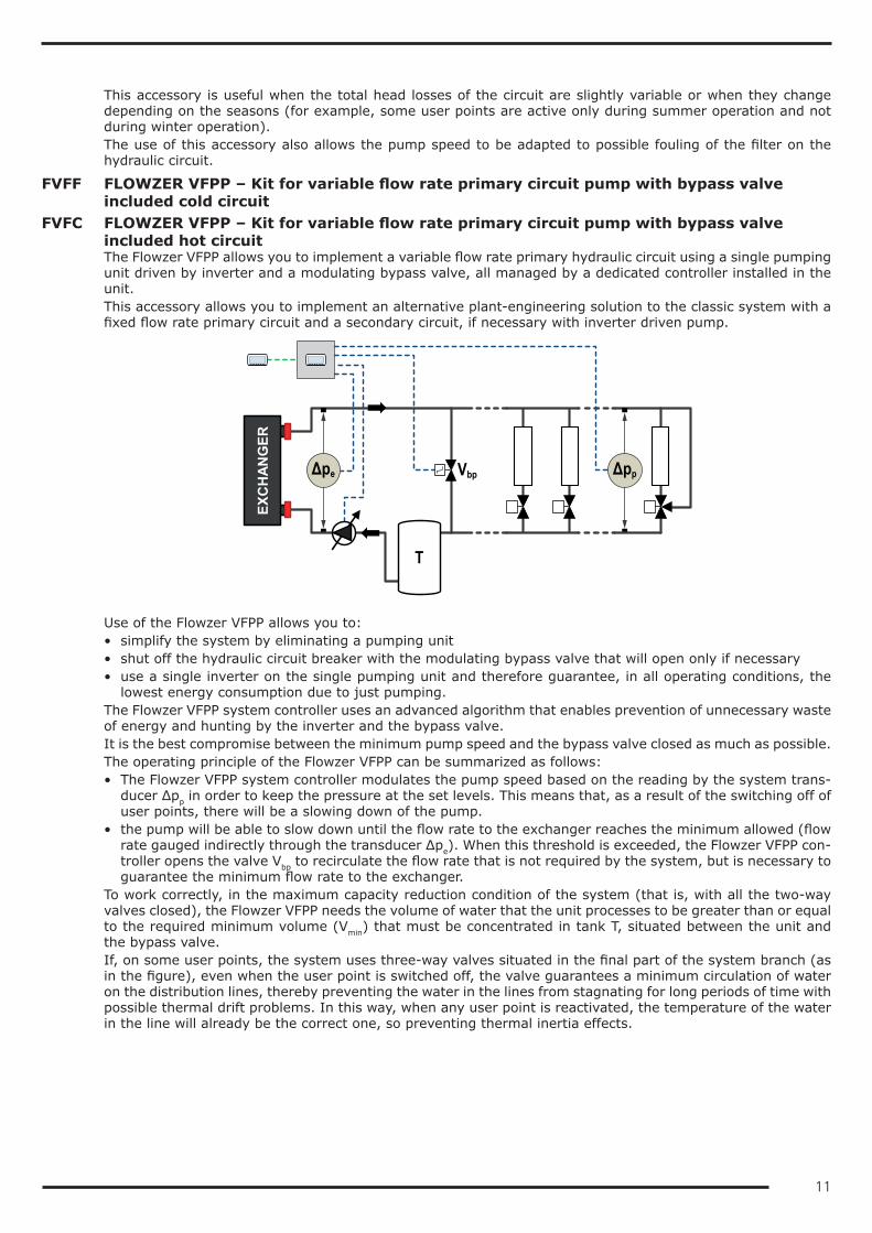
FVFC FLOWZER VFPP – Kit for variable flow rate primary circuit pump with bypass valve included hot circuitThe Flowzer VFPP allows you to implement a variable flow rate primary hydraulic circuit using a single pumping unit driven by inverter and a modulating bypass valve, all managed by a dedicated controller installed in the unit.This accessory allows you to implement an alternative plant-engineering solution to the classic system with a fixed flow rate primary circuit and a secondary circuit, if necessary with inverter driven pump.
ΔppΔpe
EXC
HAN
GER
Vbp
T
Use of the Flowzer VFPP allows you to:• simplify the system by eliminating a pumping unit• shut off the hydraulic circuit breaker with the modulating bypass valve that will open only if necessary• use a single inverter on the single pumping unit and therefore guarantee, in all operating conditions, the
lowest energy consumption due to just pumping.The Flowzer VFPP system controller uses an advanced algorithm that enables prevention of unnecessary waste of energy and hunting by the inverter and the bypass valve.It is the best compromise between the minimum pump speed and the bypass valve closed as much as possible.The operating principle of the Flowzer VFPP can be summarized as follows:• The Flowzer VFPP system controller modulates the pump speed based on the reading by the system trans-
ducer Δpp in order to keep the pressure at the set levels. This means that, as a result of the switching off of user points, there will be a slowing down of the pump.
• the pump will be able to slow down until the flow rate to the exchanger reaches the minimum allowed (flow rate gauged indirectly through the transducer Δpe). When this threshold is exceeded, the Flowzer VFPP con-troller opens the valve Vbp to recirculate the flow rate that is not required by the system, but is necessary to guarantee the minimum flow rate to the exchanger.
To work correctly, in the maximum capacity reduction condition of the system (that is, with all the two-way valves closed), the Flowzer VFPP needs the volume of water that the unit processes to be greater than or equal to the required minimum volume (Vmin) that must be concentrated in tank T, situated between the unit and the bypass valve.If, on some user points, the system uses three-way valves situated in the final part of the system branch (as in the figure), even when the user point is switched off, the valve guarantees a minimum circulation of water on the distribution lines, thereby preventing the water in the lines from stagnating for long periods of time with possible thermal drift problems. In this way, when any user point is reactivated, the temperature of the water in the line will already be the correct one, so preventing thermal inertia effects.
12
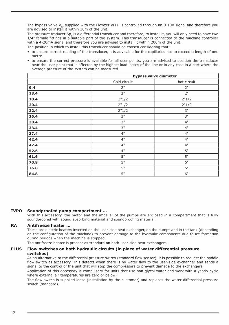
The bypass valve Vbp supplied with the Flowzer VFPP is controlled through an 0-10V signal and therefore you are advised to install it within 30m of the unit.The pressure traducer Δpp is a differential transducer and therefore, to install it, you will only need to have two 1/4" female fittings in a suitable part of the system. This transducer is connected to the machine controller with a 4-20mA signal and therefore you are advised to install it within 200m of the unit.The position in which to install this transducer should be chosen considering that:• to ensure correct reading of the transducer, it is advisable for the capillaries not to exceed a length of one
metre• to ensure the correct pressure is available for all user points, you are advised to position the transducer
near the user point that is affected by the highest load losses of the line or in any case in a part where the average pressure of the system can be measured.
Bypass valve diameter Cold circuit hot circuit9.4 2" 2"13.4 2" 2"18.4 2"1/2 2"1/220.4 2"1/2 2"1/222.4 2"1/2 3"26.4 3" 3"30.4 3" 4"33.4 3" 4"37.4 4" 4"42.4 4" 4"47.4 4" 4"52.6 4" 5"61.6 5" 5"70.8 5" 6"76.8 5" 6"84.8 5" 6"
IVPO Soundproofed pump compartment …With this accessory, the motor and the impeller of the pumps are enclosed in a compartment that is fully soundproofed with sound absorbing material and soundproofing material.
RA Antifreeze heater …These are electric heaters inserted on the user-side heat exchanger, on the pumps and in the tank (depending on the configuration of the machine) to prevent damage to the hydraulic components due to ice formation during periods when the machine is stopped.The antifreeze heater is present as standard on both user-side heat exchangers.
FLUS Flow switches on both hydraulic circuits (in place of water differential pressure switches)As an alternative to the differential pressure switch (standard flow sensor), it is possible to request the paddle flow switch as accessory. This detects when there is no water flow to the user-side exchanger and sends a signal to the control of the unit that will stop the compressors to prevent damage to the exchangers.Application of this accessory is compulsory for units that use non-glycol water and work with a yearly cycle where external air temperatures are zero or below.The flow switch is supplied loose (installation by the customer) and replaces the water differential pressure switch (standard).

13
PFPF User-side pump with Pulse function cold circuitPFPC User-side pump with Pulse function hot circuit
As standard, the unit is set to keep the system-side circulation pump on all the time, even when the set point temperature is reached.But when the unit is provided with this accessory, on reaching the set point, the controller will switch off the pump and start it again at regular intervals for a sufficient time to measure the water temperature. If the controller verifies that the water temperature is still in set point condition, it will switch off the pump again. Otherwise the controller will start the compressors again to meet the requirements of the system.This accessory therefore allows electrical absorption due to pumping to be drastically reduced, especially in spring and autumn when the load is extremely low.
V3MC 3-way modulating valve on hot circuitThe accessory involves the supply of a 3-way modulating valve to be inserted on the hot circuit in order to check that the temperature of the water entering the exchanger is always higher than the minimum allowed.This accessory obligatorily requires the option "Signal for 3-way modulating valve"Accessory supplied loose.
VSIW Safety valve on both circuits (S)With this accessory, a safety valve is inserted in the hydraulic circuit of the unit: when the calibration pressure is reached, the valve opens and, by discharging (to be routed by the customer), prevents the system pressure from reaching limits that are dangerous for the components present in the system. The valves have positive action, that is, performance is guaranteed even if the diaphragm deteriorates or breaks.The safety valve is inserted as standard on both hydraulic circuits.
14
Electrical accessoriesThe "(S)" symbol indicates that the option is present as standard in the unit, provided this is not in conflict with other selected accessories.
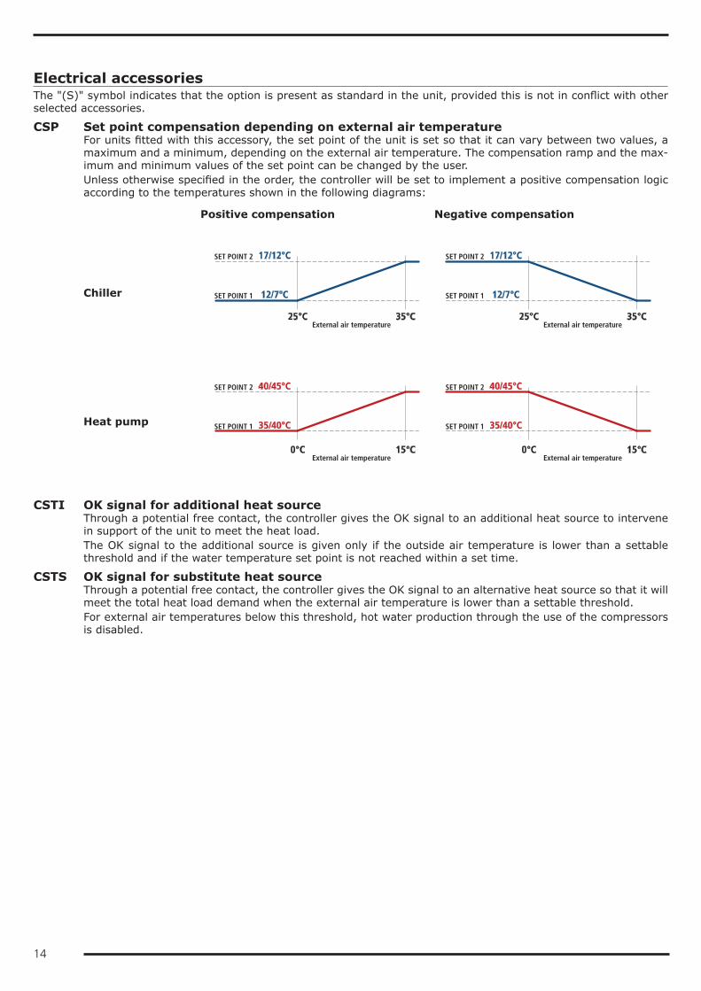
CSP Set point compensation depending on external air temperatureFor units fitted with this accessory, the set point of the unit is set so that it can vary between two values, a maximum and a minimum, depending on the external air temperature. The compensation ramp and the max-imum and minimum values of the set point can be changed by the user.Unless otherwise specified in the order, the controller will be set to implement a positive compensation logic according to the temperatures shown in the following diagrams:
Positive compensation Negative compensation
Chiller
Heat pump
SET POINT 2 17/12°C
SET POINT 1 12/7°C
25°C 35°C
SET POINT 2 17/12°C
SET POINT 1 12/7°C
25°C 35°C
SET POINT 2 40/45°C
SET POINT 1 35/40°C
0°C 15°C
SET POINT 2 40/45°C
SET POINT 1 35/40°C
0°C 15°C External air temperature External air temperature
External air temperature External air temperature
CSTI OK signal for additional heat sourceThrough a potential free contact, the controller gives the OK signal to an additional heat source to intervene in support of the unit to meet the heat load.The OK signal to the additional source is given only if the outside air temperature is lower than a settable threshold and if the water temperature set point is not reached within a set time.
CSTS OK signal for substitute heat sourceThrough a potential free contact, the controller gives the OK signal to an alternative heat source so that it will meet the total heat load demand when the external air temperature is lower than a settable threshold.For external air temperatures below this threshold, hot water production through the use of the compressors is disabled.
15
GLO Modbus Lonworks GatewayWith this accessory, a RS485/Lon gateway is installed inside the electrical control panel.By default, the programming gives read-only access to the control of the unit. Enabling of read/write access should be requested when ordering.
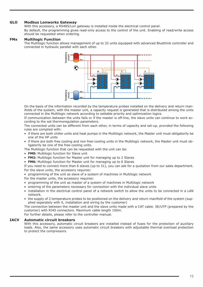
FMx Multilogic FunctionThe Multilogic function allows management of up to 32 units equipped with advanced Bluethink controller and connected in hydraulic parallel with each other.
On the basis of the information recorded by the temperature probes installed on the delivery and return man-ifolds of the system, with the master unit, a capacity request is generated that is distributed among the units connected in the Multilogic network according to settable priority and optimization logics.If communication between the units fails or if the master is off-line, the slave units can continue to work ac-cording to the set thermoregulation parameters.The connected units can be different from each other, in terms of capacity and set-up, provided the following rules are complied with:• if there are both chiller units and heat pumps in the Multilogic network, the Master unit must obligatorily be
one of the HP units• if there are both free cooling and non free-cooling units in the Multilogic network, the Master unit must ob-
ligatorily be one of the free-cooling units.The Multilogic function that can be requested with the unit can be:• FM0: Multilogic function for Slave unit• FM2: Multilogic function for Master unit for managing up to 2 Slaves• FM6: Multilogic function for Master unit for managing up to 6 SlavesIf you need to connect more than 6 slaves (up to 31), you can ask for a quotation from our sales department.For the slave units, the accessory requires:• programming of the unit as slave of a system of machines in Multilogic networkFor the master units, the accessory requires:• programming of the unit as master of a system of machines in Multilogic network• entering of the parameters necessary for connection with the individual slave units• installation in the electrical control panel of a network switch to allow the units to be connected in a LAN
network.• the supply of 2 temperature probes to be positioned on the delivery and return manifold of the system (sup-
plied separately with it, installation and wiring by the customer)The connection between the master unit and the slave units made with a CAT cable. 5E/UTP (prepared by the customer) with RJ45 connectors. Maximum cable length 100m.For further details, please refer to the controller manual.
IACV Automatic circuit breakersWith this accessory, automatic circuit breakers are installed instead of fuses for the protection of auxiliary loads. Also, the same accessory uses automatic circuit breakers with adjustable thermal overload protection to protect the compressors.
16
PBA BACnet protocol over IP (Ethernet)The controller is set for use, in read and write mode, of the BACnet port on IP protocol.By default, the programming gives read-only access to the control of the unit. Enabling of read/write access should be requested when ordering.
RE1P Relay for management of 1 external pumpR1PC Relay for management of 1 external pump hot circuit
This accessory can be requested for units without pumps and allows a pump outside the machine to be con-trolled.
R2PF Relay for management of 2 external pumps, cold circuitR2PC Relay for management of 2 external pumps, hot circuit
This accessory can be requested for units without pumps and allows two pumps outside the machine to be controlled with a running/stand-by logic by implementing a rotation on the hours of operation.
RIF Power factor correction to cosφ ≥ 0.9With this accessory, an electrical control panel, containing power factor correction condensers to bring the cosφ of the unit to being greater than 0.95, is supplied loose. The condensers should be connected (by the customer) to the electrical control panel of the unit in the specially prepared terminal board.Besides reducing the absorbed reactive power, the use of this accessory also allows the maximum absorbed current to be lowered.
RMMT Maximum and minimum voltage relayThis accessory constantly monitors the voltage value and the unit's power supply phase sequence. If the sup-ply voltage does not fall within the set parameters or there is a phase reversal, an alarm is generated that stops the machine to prevent damage to its main parts
SEDC Double set point from digital input hot circuitThe accessory allows you to preset two different operating set points and manage the change from one to the other through a digital signal.The set point temperatures must be specified when ordering. For optimization of the unit, reference will be made to the highest set point.Unless otherwise specified in the order, the controller will be set at the factory with the following temperatures:• set point 1 at 45°C• set point 2 at 40°C
SEDF Double set point from digital input cold circuitThe accessory allows you to preset two different operating set points and manage the change from one to the other through a digital signal.The set point temperatures must be specified when ordering. For optimization of the unit, reference will be made to the lowest set point.Unless otherwise specified in the order, the controller will be set at the factory with the following temperatures:• set point 1 at 7°C• set point 2 at 12°C
17
SEVC Variable set point with remote signal hot circuitThe accessory allows the set point to be varied continuously between two preset values, a maximum and a minimum, depending on an external signal that can be of the 0-1V, 0-10V or 4-20mA type.The set point temperatures and the type of signal to use for the adjustment must be specified when ordering. For optimization of the unit, reference will be made to the highest set point.Unless otherwise specified in the order, the controller will be set at the factory with 0-10V analogue input and with the following temperatures:• 0V will correspond to a set point of 45°C• 10V will correspond to a set point of 40°C
SEVF Variable set point with remote signal cold circuitThe accessory allows the set point to be varied continuously between two preset values, a maximum and a minimum, depending on an external signal that can be of the 0-1V, 0-10V or 4-20mA type.The set point temperatures and the type of signal to use for the adjustment must be specified when ordering. For optimization of the unit, reference will be made to the lowest set point.Unless otherwise specified in the order, the controller will be set at the factory with 0-10V analogue input and with the following temperatures:• 0V will correspond to a set point of 7°C• 10V will correspond to a set point of 12°C
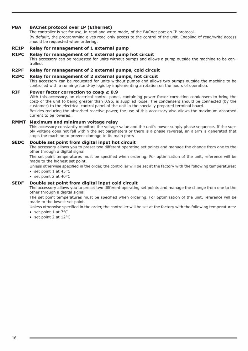
SOFT Electronic soft-starterThe scroll compressors have DOL (Direct On Line) starting and therefore the maximum inrush current IMIC will be 4/5 times its nominal current Inom.If the unit is equipped with the electronic soft-starter accessory, the starting of each compressor is done with an acceleration ramp that allows the effective value (rms value) of the inrush current of the individual com-pressor to be lowered.
rpm
I [A]
Inom
IMIC
rpm
I [A]
IMIC
Inom
Current trend without accessory Electronic soft-starter
Current trend with accessory Electronic soft-starter
If the unit is equipped with accessory "Power factor correction to cosφ ≥ 0.9", this last will be electro-mechan-ically connected only at the end of the acceleration ramp of the soft-starter.
TERM Remote-controlled user terminal panelThis accessory allows the terminal normally situated on the machine to be replicated on a support situated at a distance. It is particularly suitable when the unit is placed in an area that is not easily accessible.The accessory is supplied loose and is to be installed by the customer at a maximum distance of 120m from the unit.
SV5 Signal for 3-way modulating valveIn the electrical control panel, a 0-10V output is preset to be used to control a 3-way modulating valve inserted on the hot circuit.If the temperature of the water entering the hot exchanger is too low (for example, after the machine has been stopped for an extended period), through this signal, the controller of the unit will control the valve so as to recirculate part of the flow rate at the outlet and ensure that the unit always works within the operating limits.The 3-way modulating valve is not included in this accessory, but can be requested as further accessory.
18
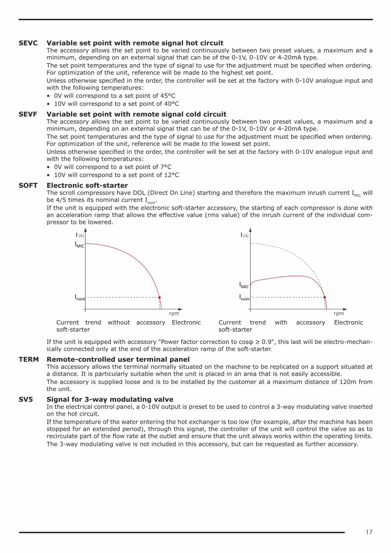
Other accessoriesAG Rubber anti-vibration mounts
These allow you to reduce the vibrations transmitted from the unit to the surface it is standing on.Accessory supplied loose.
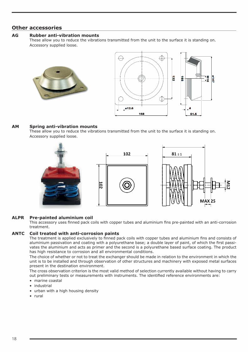
AM Spring anti-vibration mountsThese allow you to reduce the vibrations transmitted from the unit to the surface it is standing on.Accessory supplied loose.
ALPR Pre-painted aluminium coilThis accessory uses finned pack coils with copper tubes and aluminium fins pre-painted with an anti-corrosion treatment.
ANTC Coil treated with anti-corrosion paintsThe treatment is applied exclusively to finned pack coils with copper tubes and aluminium fins and consists of aluminium passivation and coating with a polyurethane base; a double layer of paint, of which the first passi-vates the aluminium and acts as primer and the second is a polyurethane based surface coating. The product has high resistance to corrosion and all environmental conditions.The choice of whether or not to treat the exchanger should be made in relation to the environment in which the unit is to be installed and through observation of other structures and machinery with exposed metal surfaces present in the destination environment.The cross observation criterion is the most valid method of selection currently available without having to carry out preliminary tests or measurements with instruments. The identified reference environments are:• marine coastal• industrial• urban with a high housing density• rural
19
Please note that in cases where different conditions co-exist, even for short periods, the choice must be suit-able for preserving the exchanger in the harsher environmental conditions and not in conditions between the worst and best situation.Particular attention must be given to cases where an environment that is not particularly aggressive becomes aggressive as a consequence of a local and/or temporal concomitant cause such as, for example, due to the presence of a heating flue outlet or an industrial kitchen or a solvent extraction fan in a small craft business.Protective treatment of the exchanger is strongly recommended if at least one of the points below is verified:• there are obvious signs of corrosion of the exposed metal surfaces in the installation area• the distance from the coast is less than 20 km• the prevailing winds come from the sea towards the unit• the environment is industrial with a significant concentration of pollutants• the environment is urban with a high population density• the environment is rural with the presence of organic discharges and effluents.For chiller units, this accessory also includes the “Cu/Al coil” accessory.
KFW Water filter kitTo protect the elements of the hydraulic circuit (in particular, the exchangers), there are Y filters that can stop and settle the particles that are normally present in the water flow and would otherwise settle in the more delicate parts of the hydraulic circuit and damage its heat exchange capacity.The kit involves the supply of a filter for each exchanger present in the machine.Installation of the water filter is mandatory even when it is not supplied as an accessory.Accessory supplied separately with the unit.
PREA Unit suitable to be disassembled on siteThe unit is delivered so that it can be disassembled easily on site if this makes the installation operations easier.A unit requested with this option is supplied:• screwed instead of riveted• with plugged and not welded pipes• without refrigerant charge• untested• covered by the warranty only if reassembled and screwed together by personnel authorized by the factory
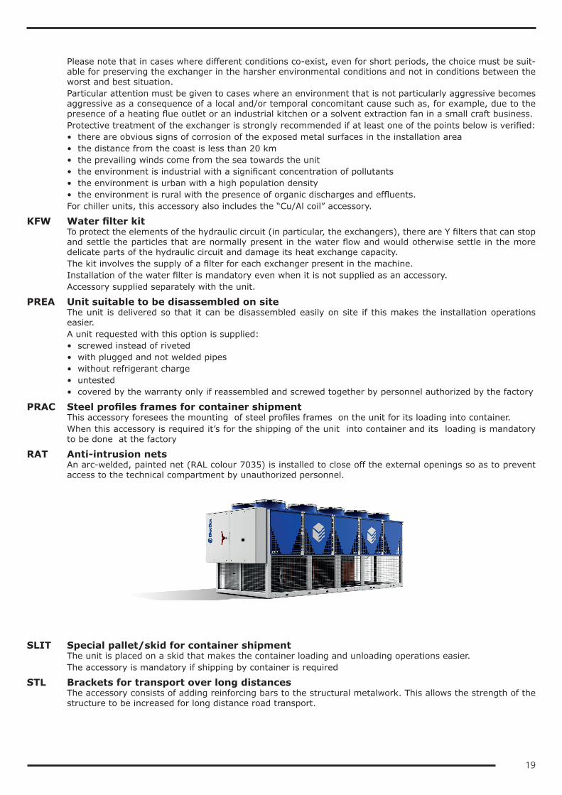
PRAC Steel profiles frames for container shipmentThis accessory foresees the mounting of steel profiles frames on the unit for its loading into container.When this accessory is required it’s for the shipping of the unit into container and its loading is mandatory to be done at the factory
RAT Anti-intrusion netsAn arc-welded, painted net (RAL colour 7035) is installed to close off the external openings so as to prevent access to the technical compartment by unauthorized personnel.
SLIT Special pallet/skid for container shipmentThe unit is placed on a skid that makes the container loading and unloading operations easier.The accessory is mandatory if shipping by container is required
STL Brackets for transport over long distancesThe accessory consists of adding reinforcing bars to the structural metalwork. This allows the strength of the structure to be increased for long distance road transport.
20
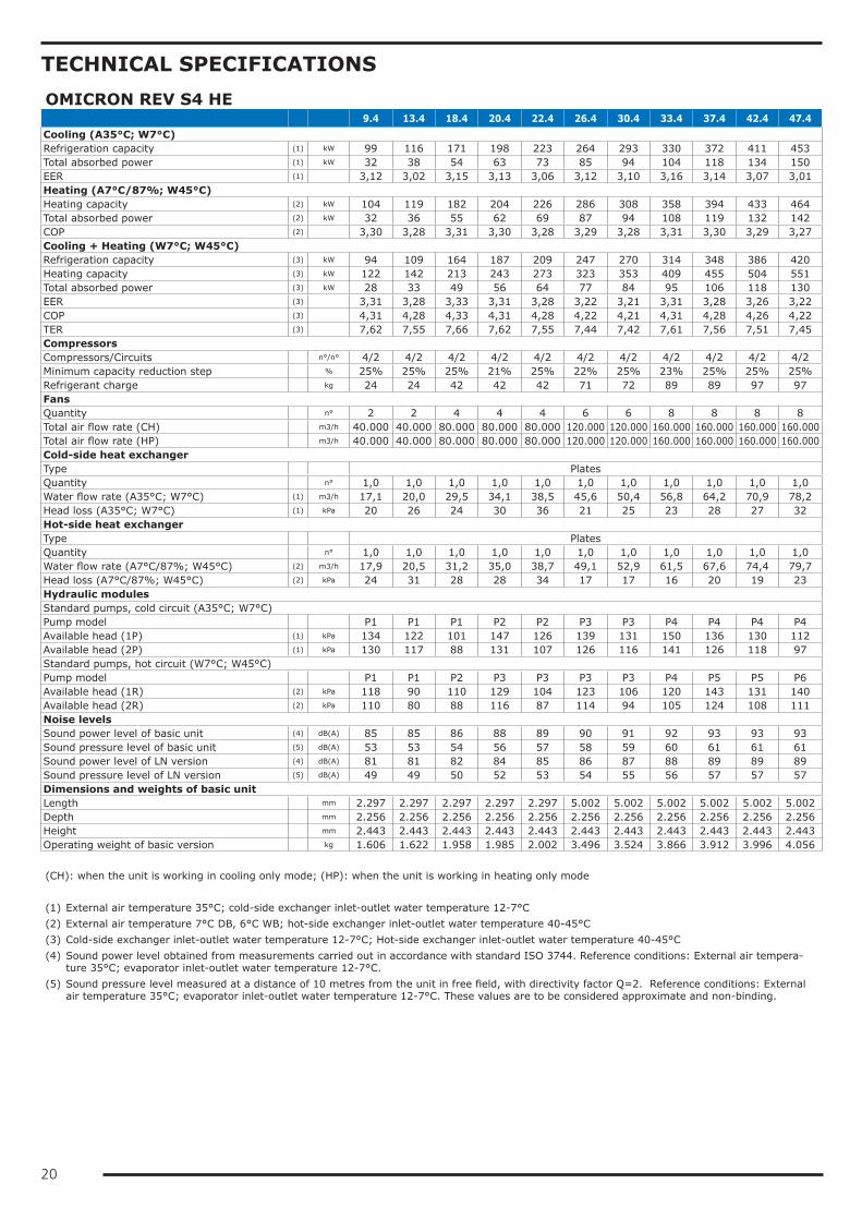
TECHNICAL SPECIFICATIONSOMICRON REV S4 HE 9.4 13.4 18.4 20.4 22.4 26.4 30.4 33.4 37.4 42.4 47.4Cooling (A35°C; W7°C)Refrigeration capacity (1) kW 99 116 171 198 223 264 293 330 372 411 453Total absorbed power (1) kW 32 38 54 63 73 85 94 104 118 134 150EER (1) 3,12 3,02 3,15 3,13 3,06 3,12 3,10 3,16 3,14 3,07 3,01Heating (A7°C/87%; W45°C)Heating capacity (2) kW 104 119 182 204 226 286 308 358 394 433 464Total absorbed power (2) kW 32 36 55 62 69 87 94 108 119 132 142COP (2) 3,30 3,28 3,31 3,30 3,28 3,29 3,28 3,31 3,30 3,29 3,27Cooling + Heating (W7°C; W45°C)Refrigeration capacity (3) kW 94 109 164 187 209 247 270 314 348 386 420Heating capacity (3) kW 122 142 213 243 273 323 353 409 455 504 551Total absorbed power (3) kW 28 33 49 56 64 77 84 95 106 118 130EER (3) 3,31 3,28 3,33 3,31 3,28 3,22 3,21 3,31 3,28 3,26 3,22COP (3) 4,31 4,28 4,33 4,31 4,28 4,22 4,21 4,31 4,28 4,26 4,22TER (3) 7,62 7,55 7,66 7,62 7,55 7,44 7,42 7,61 7,56 7,51 7,45CompressorsCompressors/Circuits n°/n° 4/2 4/2 4/2 4/2 4/2 4/2 4/2 4/2 4/2 4/2 4/2Minimum capacity reduction step % 25% 25% 25% 21% 25% 22% 25% 23% 25% 25% 25%Refrigerant charge kg 24 24 42 42 42 71 72 89 89 97 97FansQuantity n° 2 2 4 4 4 6 6 8 8 8 8Total air flow rate (CH) m3/h 40.000 40.000 80.000 80.000 80.000 120.000 120.000 160.000 160.000 160.000 160.000Total air flow rate (HP) m3/h 40.000 40.000 80.000 80.000 80.000 120.000 120.000 160.000 160.000 160.000 160.000Cold-side heat exchangerType PlatesQuantity n° 1,0 1,0 1,0 1,0 1,0 1,0 1,0 1,0 1,0 1,0 1,0Water flow rate (A35°C; W7°C) (1) m3/h 17,1 20,0 29,5 34,1 38,5 45,6 50,4 56,8 64,2 70,9 78,2Head loss (A35°C; W7°C) (1) kPa 20 26 24 30 36 21 25 23 28 27 32Hot-side heat exchangerType PlatesQuantity n° 1,0 1,0 1,0 1,0 1,0 1,0 1,0 1,0 1,0 1,0 1,0Water flow rate (A7°C/87%; W45°C) (2) m3/h 17,9 20,5 31,2 35,0 38,7 49,1 52,9 61,5 67,6 74,4 79,7Head loss (A7°C/87%; W45°C) (2) kPa 24 31 28 28 34 17 17 16 20 19 23Hydraulic modulesStandard pumps, cold circuit (A35°C; W7°C)Pump model P1 P1 P1 P2 P2 P3 P3 P4 P4 P4 P4Available head (1P) (1) kPa 134 122 101 147 126 139 131 150 136 130 112Available head (2P) (1) kPa 130 117 88 131 107 126 116 141 126 118 97Standard pumps, hot circuit (W7°C; W45°C)Pump model P1 P1 P2 P3 P3 P3 P3 P4 P5 P5 P6Available head (1R) (2) kPa 118 90 110 129 104 123 106 120 143 131 140Available head (2R) (2) kPa 110 80 88 116 87 114 94 105 124 108 111Noise levelsSound power level of basic unit (4) dB(A) 85 85 86 88 89 90 91 92 93 93 93Sound pressure level of basic unit (5) dB(A) 53 53 54 56 57 58 59 60 61 61 61Sound power level of LN version (4) dB(A) 81 81 82 84 85 86 87 88 89 89 89Sound pressure level of LN version (5) dB(A) 49 49 50 52 53 54 55 56 57 57 57Dimensions and weights of basic unitLength mm 2.297 2.297 2.297 2.297 2.297 5.002 5.002 5.002 5.002 5.002 5.002Depth mm 2.256 2.256 2.256 2.256 2.256 2.256 2.256 2.256 2.256 2.256 2.256Height mm 2.443 2.443 2.443 2.443 2.443 2.443 2.443 2.443 2.443 2.443 2.443Operating weight of basic version kg 1.606 1.622 1.958 1.985 2.002 3.496 3.524 3.866 3.912 3.996 4.056 (CH): when the unit is working in cooling only mode; (HP): when the unit is working in heating only mode (1) External air temperature 35°C; cold-side exchanger inlet-outlet water temperature 12-7°C(2) External air temperature 7°C DB, 6°C WB; hot-side exchanger inlet-outlet water temperature 40-45°C(3) Cold-side exchanger inlet-outlet water temperature 12-7°C; Hot-side exchanger inlet-outlet water temperature 40-45°C(4) Sound power level obtained from measurements carried out in accordance with standard ISO 3744. Reference conditions: External air tempera-
ture 35°C; evaporator inlet-outlet water temperature 12-7°C.(5) Sound pressure level measured at a distance of 10 metres from the unit in free field, with directivity factor Q=2. Reference conditions: External
air temperature 35°C; evaporator inlet-outlet water temperature 12-7°C. These values are to be considered approximate and non-binding.
21
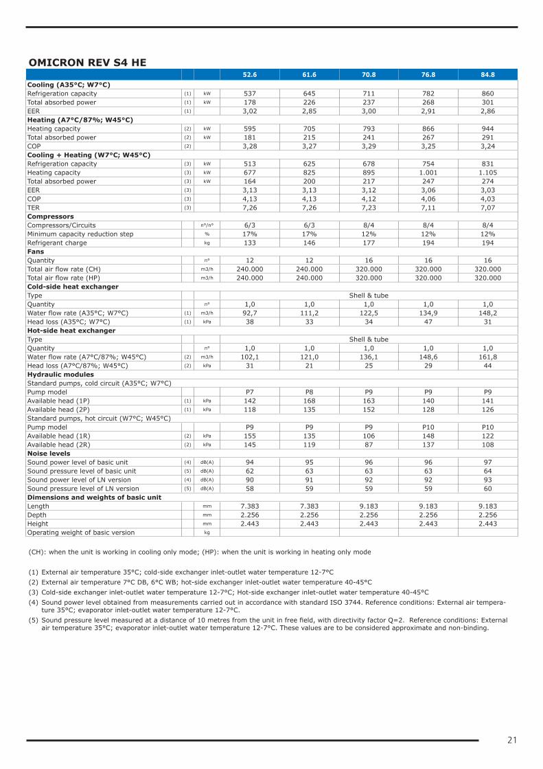
OMICRON REV S4 HE 52.6 61.6 70.8 76.8 84.8Cooling (A35°C; W7°C)Refrigeration capacity (1) kW 537 645 711 782 860Total absorbed power (1) kW 178 226 237 268 301EER (1) 3,02 2,85 3,00 2,91 2,86Heating (A7°C/87%; W45°C)Heating capacity (2) kW 595 705 793 866 944Total absorbed power (2) kW 181 215 241 267 291COP (2) 3,28 3,27 3,29 3,25 3,24Cooling + Heating (W7°C; W45°C)Refrigeration capacity (3) kW 513 625 678 754 831Heating capacity (3) kW 677 825 895 1.001 1.105Total absorbed power (3) kW 164 200 217 247 274EER (3) 3,13 3,13 3,12 3,06 3,03COP (3) 4,13 4,13 4,12 4,06 4,03TER (3) 7,26 7,26 7,23 7,11 7,07CompressorsCompressors/Circuits n°/n° 6/3 6/3 8/4 8/4 8/4Minimum capacity reduction step % 17% 17% 12% 12% 12%Refrigerant charge kg 133 146 177 194 194FansQuantity n° 12 12 16 16 16Total air flow rate (CH) m3/h 240.000 240.000 320.000 320.000 320.000Total air flow rate (HP) m3/h 240.000 240.000 320.000 320.000 320.000Cold-side heat exchangerType Shell & tubeQuantity n° 1,0 1,0 1,0 1,0 1,0Water flow rate (A35°C; W7°C) (1) m3/h 92,7 111,2 122,5 134,9 148,2Head loss (A35°C; W7°C) (1) kPa 38 33 34 47 31Hot-side heat exchangerType Shell & tubeQuantity n° 1,0 1,0 1,0 1,0 1,0Water flow rate (A7°C/87%; W45°C) (2) m3/h 102,1 121,0 136,1 148,6 161,8Head loss (A7°C/87%; W45°C) (2) kPa 31 21 25 29 44Hydraulic modulesStandard pumps, cold circuit (A35°C; W7°C)Pump model P7 P8 P9 P9 P9Available head (1P) (1) kPa 142 168 163 140 141Available head (2P) (1) kPa 118 135 152 128 126Standard pumps, hot circuit (W7°C; W45°C)Pump model P9 P9 P9 P10 P10Available head (1R) (2) kPa 155 135 106 148 122Available head (2R) (2) kPa 145 119 87 137 108Noise levelsSound power level of basic unit (4) dB(A) 94 95 96 96 97Sound pressure level of basic unit (5) dB(A) 62 63 63 63 64Sound power level of LN version (4) dB(A) 90 91 92 92 93Sound pressure level of LN version (5) dB(A) 58 59 59 59 60Dimensions and weights of basic unitLength mm 7.383 7.383 9.183 9.183 9.183Depth mm 2.256 2.256 2.256 2.256 2.256Height mm 2.443 2.443 2.443 2.443 2.443Operating weight of basic version kg (CH): when the unit is working in cooling only mode; (HP): when the unit is working in heating only mode (1) External air temperature 35°C; cold-side exchanger inlet-outlet water temperature 12-7°C(2) External air temperature 7°C DB, 6°C WB; hot-side exchanger inlet-outlet water temperature 40-45°C(3) Cold-side exchanger inlet-outlet water temperature 12-7°C; Hot-side exchanger inlet-outlet water temperature 40-45°C(4) Sound power level obtained from measurements carried out in accordance with standard ISO 3744. Reference conditions: External air tempera-
ture 35°C; evaporator inlet-outlet water temperature 12-7°C.(5) Sound pressure level measured at a distance of 10 metres from the unit in free field, with directivity factor Q=2. Reference conditions: External
air temperature 35°C; evaporator inlet-outlet water temperature 12-7°C. These values are to be considered approximate and non-binding.
22
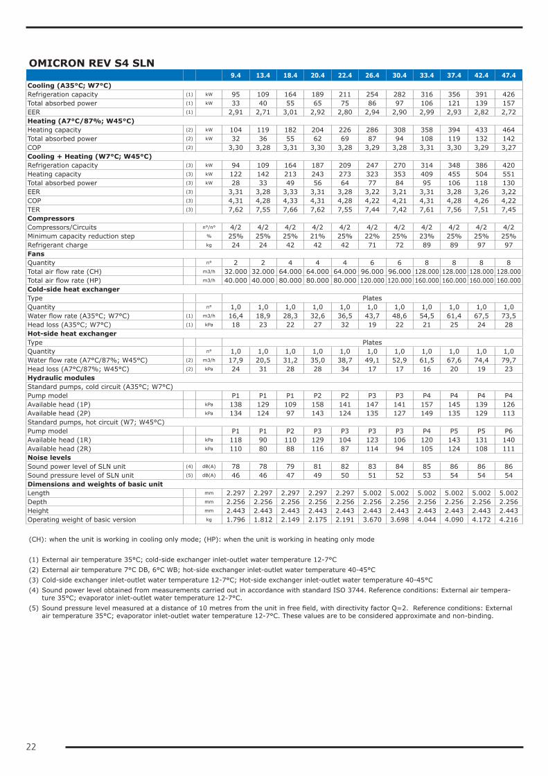
OMICRON REV S4 SLN 9.4 13.4 18.4 20.4 22.4 26.4 30.4 33.4 37.4 42.4 47.4Cooling (A35°C; W7°C)Refrigeration capacity (1) kW 95 109 164 189 211 254 282 316 356 391 426Total absorbed power (1) kW 33 40 55 65 75 86 97 106 121 139 157EER (1) 2,91 2,71 3,01 2,92 2,80 2,94 2,90 2,99 2,93 2,82 2,72Heating (A7°C/87%; W45°C)Heating capacity (2) kW 104 119 182 204 226 286 308 358 394 433 464Total absorbed power (2) kW 32 36 55 62 69 87 94 108 119 132 142COP (2) 3,30 3,28 3,31 3,30 3,28 3,29 3,28 3,31 3,30 3,29 3,27Cooling + Heating (W7°C; W45°C)Refrigeration capacity (3) kW 94 109 164 187 209 247 270 314 348 386 420Heating capacity (3) kW 122 142 213 243 273 323 353 409 455 504 551Total absorbed power (3) kW 28 33 49 56 64 77 84 95 106 118 130EER (3) 3,31 3,28 3,33 3,31 3,28 3,22 3,21 3,31 3,28 3,26 3,22COP (3) 4,31 4,28 4,33 4,31 4,28 4,22 4,21 4,31 4,28 4,26 4,22TER (3) 7,62 7,55 7,66 7,62 7,55 7,44 7,42 7,61 7,56 7,51 7,45CompressorsCompressors/Circuits n°/n° 4/2 4/2 4/2 4/2 4/2 4/2 4/2 4/2 4/2 4/2 4/2Minimum capacity reduction step % 25% 25% 25% 21% 25% 22% 25% 23% 25% 25% 25%Refrigerant charge kg 24 24 42 42 42 71 72 89 89 97 97FansQuantity n° 2 2 4 4 4 6 6 8 8 8 8Total air flow rate (CH) m3/h 32.000 32.000 64.000 64.000 64.000 96.000 96.000 128.000 128.000 128.000 128.000Total air flow rate (HP) m3/h 40.000 40.000 80.000 80.000 80.000 120.000 120.000 160.000 160.000 160.000 160.000Cold-side heat exchangerType PlatesQuantity n° 1,0 1,0 1,0 1,0 1,0 1,0 1,0 1,0 1,0 1,0 1,0Water flow rate (A35°C; W7°C) (1) m3/h 16,4 18,9 28,3 32,6 36,5 43,7 48,6 54,5 61,4 67,5 73,5Head loss (A35°C; W7°C) (1) kPa 18 23 22 27 32 19 22 21 25 24 28Hot-side heat exchangerType PlatesQuantity n° 1,0 1,0 1,0 1,0 1,0 1,0 1,0 1,0 1,0 1,0 1,0Water flow rate (A7°C/87%; W45°C) (2) m3/h 17,9 20,5 31,2 35,0 38,7 49,1 52,9 61,5 67,6 74,4 79,7Head loss (A7°C/87%; W45°C) (2) kPa 24 31 28 28 34 17 17 16 20 19 23Hydraulic modulesStandard pumps, cold circuit (A35°C; W7°C)Pump model P1 P1 P1 P2 P2 P3 P3 P4 P4 P4 P4Available head (1P) kPa 138 129 109 158 141 147 141 157 145 139 126Available head (2P) kPa 134 124 97 143 124 135 127 149 135 129 113Standard pumps, hot circuit (W7; W45°C)Pump model P1 P1 P2 P3 P3 P3 P3 P4 P5 P5 P6Available head (1R) kPa 118 90 110 129 104 123 106 120 143 131 140Available head (2R) kPa 110 80 88 116 87 114 94 105 124 108 111Noise levelsSound power level of SLN unit (4) dB(A) 78 78 79 81 82 83 84 85 86 86 86Sound pressure level of SLN unit (5) dB(A) 46 46 47 49 50 51 52 53 54 54 54Dimensions and weights of basic unitLength mm 2.297 2.297 2.297 2.297 2.297 5.002 5.002 5.002 5.002 5.002 5.002Depth mm 2.256 2.256 2.256 2.256 2.256 2.256 2.256 2.256 2.256 2.256 2.256Height mm 2.443 2.443 2.443 2.443 2.443 2.443 2.443 2.443 2.443 2.443 2.443Operating weight of basic version kg 1.796 1.812 2.149 2.175 2.191 3.670 3.698 4.044 4.090 4.172 4.216 (CH): when the unit is working in cooling only mode; (HP): when the unit is working in heating only mode (1) External air temperature 35°C; cold-side exchanger inlet-outlet water temperature 12-7°C(2) External air temperature 7°C DB, 6°C WB; hot-side exchanger inlet-outlet water temperature 40-45°C(3) Cold-side exchanger inlet-outlet water temperature 12-7°C; Hot-side exchanger inlet-outlet water temperature 40-45°C(4) Sound power level obtained from measurements carried out in accordance with standard ISO 3744. Reference conditions: External air tempera-
ture 35°C; evaporator inlet-outlet water temperature 12-7°C.(5) Sound pressure level measured at a distance of 10 metres from the unit in free field, with directivity factor Q=2. Reference conditions: External
air temperature 35°C; evaporator inlet-outlet water temperature 12-7°C. These values are to be considered approximate and non-binding.
23
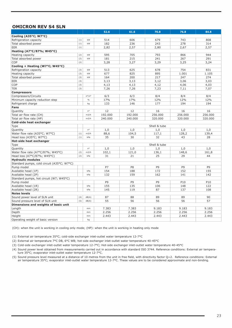
OMICRON REV S4 SLN 52.6 61.6 70.8 76.8 84.8Cooling (A35°C; W7°C)Refrigeration capacity (1) kW 514 606 679 743 808Total absorbed power (1) kW 182 236 243 278 314EER (1) 2,82 2,57 2,80 2,67 2,57Heating (A7°C/87%; W45°C)Heating capacity (2) kW 595 705 793 866 944Total absorbed power (2) kW 181 215 241 267 291COP (2) 3,28 3,27 3,29 3,25 3,24Cooling + Heating (W7°C; W45°C)Refrigeration capacity (3) kW 513 625 678 754 831Heating capacity (3) kW 677 825 895 1.001 1.105Total absorbed power (3) kW 164 200 217 247 274EER (3) 3,13 3,13 3,12 3,06 3,03COP (3) 4,13 4,13 4,12 4,06 4,03TER (3) 7,26 7,26 7,23 7,11 7,07CompressorsCompressors/Circuits n°/n° 6/3 6/3 8/4 8/4 8/4Minimum capacity reduction step % 17% 17% 12% 12% 12%Refrigerant charge kg 133 146 177 194 194FansQuantity n° 12 12 16 16 16Total air flow rate (CH) m3/h 192.000 192.000 256.000 256.000 256.000Total air flow rate (HP) m3/h 240.000 240.000 320.000 320.000 320.000Cold-side heat exchangerType Shell & tubeQuantity n° 1,0 1,0 1,0 1,0 1,0Water flow rate (A35°C; W7°C) (1) m3/h 88,6 104,5 117,1 128,2 139,4Head loss (A35°C; W7°C) (1) kPa 35 30 32 43 28Hot-side heat exchangerType Shell & tubeQuantity n° 1,0 1,0 1,0 1,0 1,0Water flow rate (A7°C/87%; W45°C) (2) m3/h 102,1 121,0 136,1 148,6 161,8Head loss (A7°C/87%; W45°C) (2) kPa 31 21 25 29 44Hydraulic modulesStandard pumps, cold circuit (A35°C; W7°C)Pump model P7 P8 P9 P9 P9Available head (1P) kPa 154 188 172 152 155Available head (2P) kPa 132 159 162 141 142Standard pumps, hot circuit (W7; W45°C)Pump model P9 P9 P9 P10 P10Available head (1R) kPa 155 135 106 148 122Available head (2R) kPa 145 119 87 137 108Noise levelsSound power level of SLN unit (4) dB(A) 87 88 89 89 90Sound pressure level of SLN unit (5) dB(A) 55 56 56 56 57Dimensions and weights of basic unitLength mm 7.383 7.383 9.183 9.183 9.183Depth mm 2.256 2.256 2.256 2.256 2.256Height mm 2.443 2.443 2.443 2.443 2.443Operating weight of basic version kg (CH): when the unit is working in cooling only mode; (HP): when the unit is working in heating only mode (1) External air temperature 35°C; cold-side exchanger inlet-outlet water temperature 12-7°C(2) External air temperature 7°C DB, 6°C WB; hot-side exchanger inlet-outlet water temperature 40-45°C(3) Cold-side exchanger inlet-outlet water temperature 12-7°C; Hot-side exchanger inlet-outlet water temperature 40-45°C(4) Sound power level obtained from measurements carried out in accordance with standard ISO 3744. Reference conditions: External air tempera-
ture 35°C; evaporator inlet-outlet water temperature 12-7°C.(5) Sound pressure level measured at a distance of 10 metres from the unit in free field, with directivity factor Q=2. Reference conditions: External
air temperature 35°C; evaporator inlet-outlet water temperature 12-7°C. These values are to be considered approximate and non-binding.
24
ELECTRICAL SPECIFICATIONSOMICRON REV S4 HE - OMICRON REV S4 SLN 9.4 13.4 18.4 20.4 22.4 26.4General electrical specificationsMax. absorbed power (FLI) (1) kW 44 52 82 95 108 128Max. absorbed current (FLA) (1) A 78 91 138 151 163 202Nominal current (Inom) (2) A 66 75 120 128 138 145cosφ standard unit (2) 0,79 0,79 0,76 0,81 0,82 0,86Nominal current with power factor correction (Inom)
(2) A 54 62 99 109 109 128
cosφ unit with power factor correction (2) 0,97 0,96 0,95 0,95 0,95 0,97Maximum inrush current (MIC) (3) A 172 189 282 339 352 364Maximum inrush current with soft-starter (MIC) (4) A 127 142 213 249 262 280Power supply 400/3~/52Power supply for auxiliary circuits 230-24/1~/52Suggested line section (5) mm² 3x25+1G18 3x35+1G27 3x50+1G27 3x70+1G37 3x70+1G37 3x120+1G72Suggested line protection (6) NH00gG 100A NH00gG 125A NH00gG 160A NH1gG 200A NH1gG 200A NH1gG 250AElectrical specifications for fansRated power of standard fan n° x kW 2 x 2,0 2 x 2,0 4 x 2,0 4 x 2,0 4 x 2,0 6 x 2,0Rated current of standard fan n° x A 2 x 4,3 2 x 4,3 4 x 4,3 4 x 4,3 4 x 4,3 6 x 4,3Rated power of EC fan n° x kW 2 x 1,9 2 x 1,9 4 x 1,9 4 x 1,9 4 x 1,9 6 x 1,9Rated current of EC fan n° x A 2 x 2,9 2 x 2,9 4 x 2,9 4 x 2,9 4 x 2,9 6 x 2,9Rated power of oversize EC fans n° x kW 2 x 3,0 2 x 3,0 4 x 3,0 4 x 3,0 4 x 3,0 6 x 3,0Rated current of oversize EC fans n° x A 2 x 4,5 2 x 4,5 4 x 4,5 4 x 4,5 4 x 4,5 6 x 4,5
30.4 33.4 37.4 42.4 47.4General electrical specificationsMax. absorbed power (FLI) (1) kW 140 157 170 190 204Max. absorbed current (FLA) (1) A 218 254 282 320 341Nominal current (Inom) (2) A 152 193 226 258 273cosφ standard unit (2) 0,87 0,87 0,88 0,85 0,86Nominal current with power factor correction (Inom)
(2) A 137 176 208 228 244
cosφ unit with power factor correction (2) 0,97 0,96 0,95 0,96 0,96Maximum inrush current (MIC) (3) A 380 479 507 515 563Maximum inrush current with soft-starter (MIC) (4) A 296 365 392 409 443Power supply 400/3~/52Power supply for auxiliary circuits 230-24/1~/52Suggested line section (5) mm² 3x120+1G72 3x150+1G97 3x150+1G97 2x(3x70) +1G97 2x(3x70) +1G97Suggested line protection (6) NH1gG 250A NH2gG 315A NH2gG 315A NH2gG 400A NH2gG 400AElectrical specifications for fansRated power of standard fan n° x kW 6 x 2,0 8 x 2,0 8 x 2,0 8 x 2,0 8 x 2,0Rated current of standard fan n° x A 6 x 4,3 8 x 4,3 8 x 4,3 8 x 4,3 8 x 4,3Rated power of EC fan n° x kW 6 x 1,9 8 x 1,9 8 x 1,9 8 x 1,9 8 x 1,9Rated current of EC fan n° x A 6 x 2,9 8 x 2,9 8 x 2,9 8 x 2,9 8 x 2,9Rated power of oversize EC fans n° x kW 6 x 3,0 8 x 3,0 8 x 3,0 8 x 3,0 8 x 3,0Rated current of oversize EC fans n° x A 6 x 4,5 8 x 4,5 8 x 4,5 8 x 4,5 8 x 4,5 (1) Data regarding the unit without accessories working in maximum power absorption conditions(2) Datum related to the unit without accessories working in standard conditions (A35°C; W12-7°C)(3) Maximum effective RMS value of the current when the last compressor starts (FLA of the entire unit - FLA of the largest compressor + LRA of the
largest compressor)(4) Maximum effective RMS value of the current when the last compressor starts (FLA of the entire unit - FLA of the largest compressor + 0.6 x LRA
of the largest compressor)(5) These values are determined for cables with operating temperature of 40°C, EPR insulation and a line with a maximum length of 50m. The line
section must be determined by a qualified technician based on the protection devices, the length of the line, the type of cable used and the type of installation.
(6) The correct line protection part must be determined by a qualified technician based on the length of the line, the type of cable used and the type of installation.
25
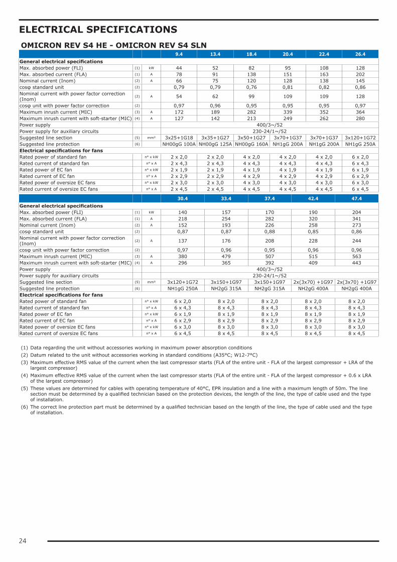
OMICRON REV S4 HE - OMICRON REV S4 SLN 52.6 61.6 70.8 76.8 84.8General electrical specificationsMax. absorbed power (FLI) (1) kW 255 307 340 380 409Max. absorbed current (FLA) (1) A 423 512 564 639 682Nominal current (Inom) (2) A cosφ standard unit (2) Nominal current with power factor correction (Inom)
(2) A
cosφ unit with power factor correction (2) Maximum inrush current (MIC) (3) A 648 733 789 835 904Maximum inrush current with soft-starter (MIC) (4) A 533 614 674 728 785Power supply 400/3~/52Power supply for auxiliary circuits 230-24/1~/52Suggested line section (5) mm² Suggested line protection (6) Electrical specifications for fansRated power of standard fan n° x kW 12 x 2,0 12 x 2,0 16 x 2,0 16 x 2,0 16 x 2,0Rated current of standard fan n° x A 12 x 4,3 12 x 4,3 16 x 4,3 16 x 4,3 16 x 4,3Rated power of EC fan n° x kW 12 x 1,9 12 x 1,9 16 x 1,9 16 x 1,9 16 x 1,9Rated current of EC fan n° x A 12 x 2,9 12 x 2,9 16 x 2,9 16 x 2,9 16 x 2,9Rated power of oversize EC fans n° x kW 12 x 3,0 12 x 3,0 16 x 3,0 16 x 3,0 16 x 3,0Rated current of oversize EC fans n° x A 12 x 4,5 12 x 4,5 16 x 4,5 16 x 4,5 16 x 4,5 (1) Data regarding the unit without accessories working in maximum power absorption conditions(2) Datum related to the unit without accessories working in standard conditions (A35°C; W12-7°C)(3) Maximum effective RMS value of the current when the last compressor starts (FLA of the entire unit - FLA of the largest compressor + LRA of the
largest compressor)(4) Maximum effective RMS value of the current when the last compressor starts (FLA of the entire unit - FLA of the largest compressor + 0.6 x LRA
of the largest compressor)(5) These values are determined for cables with operating temperature of 40°C, EPR insulation and a line with a maximum length of 50m. The line
section must be determined by a qualified technician based on the protection devices, the length of the line, the type of cable used and the type of installation.
(6) The correct line protection part must be determined by a qualified technician based on the length of the line, the type of cable used and the type of installation.
PUMP DATAModel Rated power Rated current Qmin Qmax
kW A m3/h m3/h
P1 1,5 3,2 12 42
P2 2,2 4,5 12 42
P3 3,0 6,4 24 72
P4 4,0 8,7 38 110
P5 5,5 10,6 42 126
P6 7,5 13,6 42 132
P7 7,5 13,6 42 126
P8 9,2 17,2 42 132
P9 11,0 20,2 58 237
P10 15,0 26,6 76 290
26
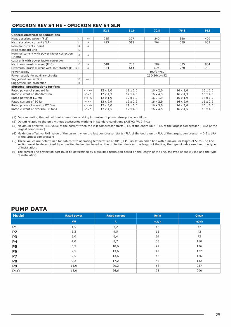
USER-SIDE EXCHANGER FLOW RATE FIELDSThe units are sized and optimized for the following nominal conditions: external air 35°C, inlet-outlet of the user-side exchanger 12/7°C.The units can work at design conditions different from nominal conditions, provided that:• the design condition falls within the operating limits specified below• the unit is equipped with all the accessories necessary for operation (e.g. brine kit, fan speed adjuster, HAT)• the flow rate at design conditions (that is, of the specific application) must always come within the allowed flow rate
ranges specified below. If the design conditions require a water flow rate that does not come within the allowed operating range, you must contact our sales department that will identify the most suitable solution for the specific application.
OMICRON REV S4 HE Cold-side heat exchanger Hot-side heat exchanger
Qmin Qmax Qmin Qmax
m³/h m³/h m³/h m³/h
9.4 8,5 25,6 8,9 26,8
13.4 10,0 30,0 10,2 30,7
18.4 14,7 44,2 15,6 46,7
20.4 17,1 51,2 17,5 52,5
22.4 19,2 57,7 19,4 58,1
26.4 22,8 68,3 24,5 73,6
30.4 25,2 75,7 26,5 79,4
33.4 28,4 85,2 30,7 92,2
37.4 32,1 96,3 33,8 101,3
42.4 35,5 106,4 37,2 111,6
47.4 39,1 117,2 39,9 119,6
52.6 46,4 139,1 51,0 153,1
61.6 55,6 166,8 60,5 181,5
70.8 61,3 183,8 68,0 204,1
76.8 67,5 202,4 74,3 222,9
84.8 74,1 222,4 80,9 242,7
OMICRON REV S4 SLN Cold-side heat exchanger Hot-side heat exchanger
Qmin Qmax Qmin Qmax
m³/h m³/h m³/h m³/h
9.4 8,2 24,6 8,9 26,8
13.4 9,4 28,3 10,2 30,7
18.4 14,2 42,5 15,6 46,7
20.4 16,3 48,9 17,5 52,5
22.4 18,2 54,7 19,4 58,1
26.4 21,9 65,6 24,5 73,6
30.4 24,3 73,0 26,5 79,4
33.4 27,3 81,8 30,7 92,2
37.4 30,7 92,0 33,8 101,3
42.4 33,7 101,2 37,2 111,6
47.4 36,7 110,2 39,9 119,6
52.6 44,3 132,9 51,0 153,1
61.6 52,3 156,8 60,5 181,5
70.8 58,6 175,7 68,0 204,1
76.8 64,1 192,3 74,3 222,9
84.8 69,7 209,0 80,9 242,7
27
OPERATING LIMITS
HEATING
40
45
50
25
30
35
55
60
65
70
-25 -20 -15 -10 -5 0 5 10 15 20 25 30 35 40 45 50 55
Ta [°C]
LWTu
[°C]
FU
COOLING
0
5
-10
-5
10
15
20
-25 -20 -15 -10 -5 0 5 10 15 20 25 30 35 40 45 50 55
Ta [°C]
LWTu
[°C]
HATLW FU
BK
COOLING+HEATING
-10
-5
10
15
20
0
5
25 30 35 40 45 50 55 60 65
LWTr [°C]
LWTu
[°C]
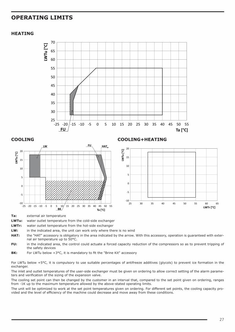
Ta: external air temperatureLWTu: water outlet temperature from the cold-side exchangerLWTr: water outlet temperature from the hot-side exchangerLW: in the indicated area, the unit can work only where there is no windHAT: the "HAT" accessory is obligatory in the area indicated by the arrow. With this accessory, operation is guaranteed with exter-
nal air temperature up to 50°C.FU: in the indicated area, the control could actuate a forced capacity reduction of the compressors so as to prevent tripping of
the safety devicesBK: For LWTu below +3°C, it is mandatory to fit the "Brine Kit" accessory For LWTu below +5°C, it is compulsory to use suitable percentages of antifreeze additives (glycols) to prevent ice formation in the exchanger.The inlet and outlet temperatures of the user-side exchanger must be given on ordering to allow correct setting of the alarm parame-ters and verification of the sizing of the expansion valve.The cooling set point can then be changed by the customer in an interval that, compared to the set point given on ordering, ranges from -1K up to the maximum temperature allowed by the above-stated operating limits.The unit will be optimized to work at the set point temperatures given on ordering. For different set points, the cooling capacity pro-vided and the level of efficiency of the machine could decrease and move away from these conditions.
28
NOISE LEVELSOMICRON REV S4 HE
Octave bands [dB] Total
[dB(A)]63 Hz 125 Hz 250 Hz 500 Hz 1000 Hz 2000 Hz 4000 Hz 8000 HzLw Lp Lw Lp Lw Lp Lw Lp Lw Lp Lw Lp Lw Lp Lw Lp Lw Lp
9.4 89 57 78 46 77 45 81 49 79 47 79 47 76 44 71 39 85 5313.4 89 57 78 46 77 45 81 49 80 48 79 47 75 43 70 38 85 5318.4 90 58 79 47 78 46 80 48 81 49 81 49 76 44 72 40 86 5420.4 89 57 79 47 80 48 82 50 81 49 84 52 77 45 71 39 88 5622.4 89 57 79 47 81 49 82 50 82 50 85 53 78 46 69 37 89 5726.4 92 59 82 49 82 49 85 53 86 53 84 52 78 46 73 41 90 5830.4 93 60 83 50 82 50 86 53 86 54 86 53 79 47 74 42 91 5933.4 94 61 84 51 83 51 88 55 87 55 86 54 81 48 78 45 92 6037.4 94 62 84 52 84 51 89 57 88 56 87 54 82 49 80 48 93 6142.4 94 62 84 52 86 54 89 56 88 55 85 53 80 48 87 55 93 6147.4 93 60 83 50 87 54 90 57 90 57 85 52 80 48 77 44 93 6152.6 95 63 85 53 85 52 90 58 89 57 88 55 83 50 81 49 94 6261.6 95 62 85 52 89 56 92 59 92 59 87 54 82 50 78 46 95 6370.8 97 64 87 54 87 54 92 59 91 58 90 57 85 52 83 50 96 6376.8 97 64 87 54 89 56 92 59 91 58 88 55 83 50 90 57 96 6384.8 97 64 87 54 90 57 94 61 94 61 89 56 84 51 80 47 97 64
OMICRON REV S4 HE/LN
Octave bands [dB] Total
[dB(A)]63 Hz 125 Hz 250 Hz 500 Hz 1000 Hz 2000 Hz 4000 Hz 8000 HzLw Lp Lw Lp Lw Lp Lw Lp Lw Lp Lw Lp Lw Lp Lw Lp Lw Lp
9.4 84 52 74 42 73 41 77 45 75 43 75 43 72 40 67 35 81 4913.4 84 52 74 42 73 41 77 45 76 44 75 43 71 39 67 35 81 4918.4 85 53 75 43 74 42 76 44 77 45 77 45 73 41 68 36 82 5020.4 85 53 75 43 76 44 78 46 78 46 80 48 73 41 67 35 84 5222.4 85 53 75 43 78 46 78 46 78 46 81 49 74 42 66 34 85 5326.4 87 55 78 45 78 46 81 49 82 49 80 48 75 42 70 37 86 5430.4 88 56 79 46 79 46 82 49 82 50 82 49 76 43 71 38 87 5533.4 89 57 80 47 79 47 84 51 83 51 82 50 77 44 74 42 88 5637.4 90 57 80 48 80 47 85 53 84 52 83 50 78 46 76 44 89 5742.4 90 57 80 48 82 50 85 52 84 51 81 49 77 44 83 51 89 5747.4 89 56 79 47 83 50 86 53 86 53 81 48 77 44 73 40 89 5752.6 91 58 81 49 81 48 86 53 85 53 84 51 79 47 77 45 90 5861.6 91 58 81 49 85 52 88 55 88 55 83 50 79 46 75 43 91 5970.8 93 60 83 50 83 50 88 55 87 54 86 53 81 48 79 46 92 5976.8 93 60 84 51 85 52 88 55 87 54 84 51 80 47 86 53 92 5984.8 93 60 83 50 87 54 90 57 90 57 85 52 81 48 77 44 93 60
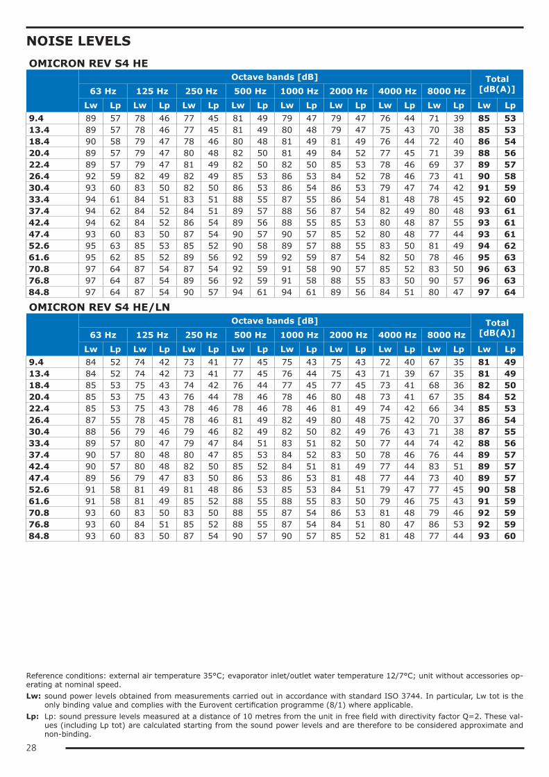
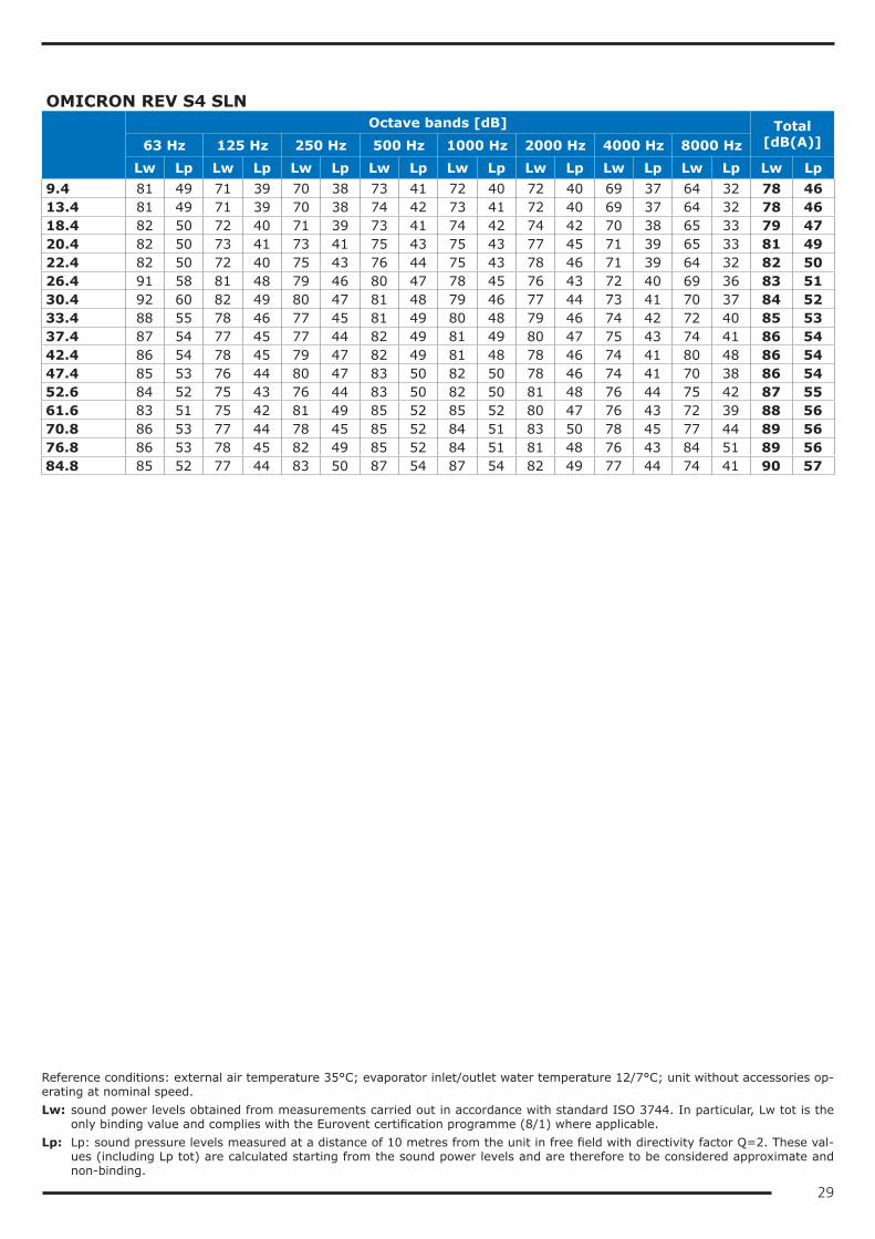
Reference conditions: external air temperature 35°C; evaporator inlet/outlet water temperature 12/7°C; unit without accessories op-erating at nominal speed.Lw: sound power levels obtained from measurements carried out in accordance with standard ISO 3744. In particular, Lw tot is the
only binding value and complies with the Eurovent certification programme (8/1) where applicable.Lp: Lp: sound pressure levels measured at a distance of 10 metres from the unit in free field with directivity factor Q=2. These val-
ues (including Lp tot) are calculated starting from the sound power levels and are therefore to be considered approximate and non-binding.
29
OMICRON REV S4 SLN
Octave bands [dB] Total
[dB(A)]63 Hz 125 Hz 250 Hz 500 Hz 1000 Hz 2000 Hz 4000 Hz 8000 HzLw Lp Lw Lp Lw Lp Lw Lp Lw Lp Lw Lp Lw Lp Lw Lp Lw Lp
9.4 81 49 71 39 70 38 73 41 72 40 72 40 69 37 64 32 78 4613.4 81 49 71 39 70 38 74 42 73 41 72 40 69 37 64 32 78 4618.4 82 50 72 40 71 39 73 41 74 42 74 42 70 38 65 33 79 4720.4 82 50 73 41 73 41 75 43 75 43 77 45 71 39 65 33 81 4922.4 82 50 72 40 75 43 76 44 75 43 78 46 71 39 64 32 82 5026.4 91 58 81 48 79 46 80 47 78 45 76 43 72 40 69 36 83 5130.4 92 60 82 49 80 47 81 48 79 46 77 44 73 41 70 37 84 5233.4 88 55 78 46 77 45 81 49 80 48 79 46 74 42 72 40 85 5337.4 87 54 77 45 77 44 82 49 81 49 80 47 75 43 74 41 86 5442.4 86 54 78 45 79 47 82 49 81 48 78 46 74 41 80 48 86 5447.4 85 53 76 44 80 47 83 50 82 50 78 46 74 41 70 38 86 5452.6 84 52 75 43 76 44 83 50 82 50 81 48 76 44 75 42 87 5561.6 83 51 75 42 81 49 85 52 85 52 80 47 76 43 72 39 88 5670.8 86 53 77 44 78 45 85 52 84 51 83 50 78 45 77 44 89 5676.8 86 53 78 45 82 49 85 52 84 51 81 48 76 43 84 51 89 5684.8 85 52 77 44 83 50 87 54 87 54 82 49 77 44 74 41 90 57
Reference conditions: external air temperature 35°C; evaporator inlet/outlet water temperature 12/7°C; unit without accessories op-erating at nominal speed.Lw: sound power levels obtained from measurements carried out in accordance with standard ISO 3744. In particular, Lw tot is the
only binding value and complies with the Eurovent certification programme (8/1) where applicable.Lp: Lp: sound pressure levels measured at a distance of 10 metres from the unit in free field with directivity factor Q=2. These val-
ues (including Lp tot) are calculated starting from the sound power levels and are therefore to be considered approximate and non-binding.
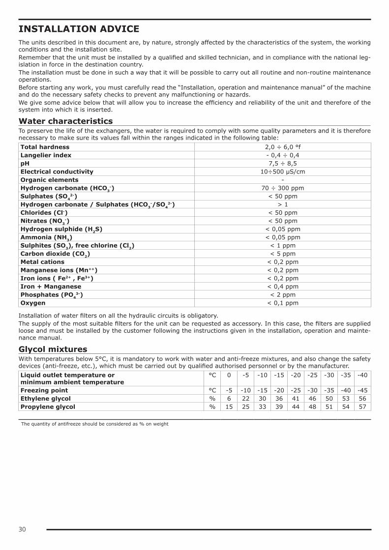
30
INSTALLATION ADVICEThe units described in this document are, by nature, strongly affected by the characteristics of the system, the working conditions and the installation site.Remember that the unit must be installed by a qualified and skilled technician, and in compliance with the national leg-islation in force in the destination country.The installation must be done in such a way that it will be possible to carry out all routine and non-routine maintenance operations.Before starting any work, you must carefully read the “Installation, operation and maintenance manual” of the machine and do the necessary safety checks to prevent any malfunctioning or hazards.We give some advice below that will allow you to increase the efficiency and reliability of the unit and therefore of the system into which it is inserted.
Water characteristicsTo preserve the life of the exchangers, the water is required to comply with some quality parameters and it is therefore necessary to make sure its values fall within the ranges indicated in the following table:Total hardness 2,0 ÷ 6,0 °fLangelier index - 0,4 ÷ 0,4pH 7,5 ÷ 8,5Electrical conductivity 10÷500 µS/cmOrganic elements -Hydrogen carbonate (HCO3
-) 70 ÷ 300 ppmSulphates (SO4
2-) < 50 ppmHydrogen carbonate / Sulphates (HCO3
-/SO42-) > 1
Chlorides (Cl-) < 50 ppmNitrates (NO3
-) < 50 ppmHydrogen sulphide (H2S) < 0,05 ppmAmmonia (NH3) < 0,05 ppmSulphites (SO3), free chlorine (Cl2) < 1 ppmCarbon dioxide (CO2) < 5 ppmMetal cations < 0,2 ppmManganese ions (Mn++) < 0,2 ppmIron ions ( Fe2+ , Fe3+) < 0,2 ppmIron + Manganese < 0,4 ppmPhosphates (PO4
3-) < 2 ppmOxygen < 0,1 ppm
Installation of water filters on all the hydraulic circuits is obligatory.The supply of the most suitable filters for the unit can be requested as accessory. In this case, the filters are supplied loose and must be installed by the customer following the instructions given in the installation, operation and mainte-nance manual.
Glycol mixturesWith temperatures below 5°C, it is mandatory to work with water and anti-freeze mixtures, and also change the safety devices (anti-freeze, etc.), which must be carried out by qualified authorised personnel or by the manufacturer.Liquid outlet temperature or minimum ambient temperature
°C 0 -5 -10 -15 -20 -25 -30 -35 -40
Freezing point °C -5 -10 -15 -20 -25 -30 -35 -40 -45Ethylene glycol % 6 22 30 36 41 46 50 53 56Propylene glycol % 15 25 33 39 44 48 51 54 57
The quantity of antifreeze should be considered as % on weight
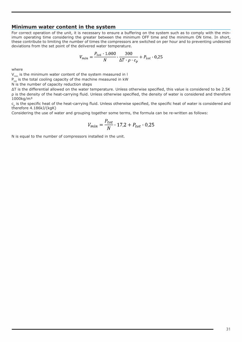
31
Minimum water content in the systemFor correct operation of the unit, it is necessary to ensure a buffering on the system such as to comply with the min-imum operating time considering the greater between the minimum OFF time and the minimum ON time. In short, these contribute to limiting the number of times the compressors are switched on per hour and to preventing undesired deviations from the set point of the delivered water temperature.
whereVmin is the minimum water content of the system measured in lPtot is the total cooling capacity of the machine measured in kWN is the number of capacity reduction stepsΔΤ is the differential allowed on the water temperature. Unless otherwise specified, this value is considered to be 2.5Kρ is the density of the heat-carrying fluid. Unless otherwise specified, the density of water is considered and therefore 1000kg/m³cp is the specific heat of the heat-carrying fluid. Unless otherwise specified, the specific heat of water is considered and therefore 4.186kJ/(kgK)Considering the use of water and grouping together some terms, the formula can be re-written as follows:
N is equal to the number of compressors installed in the unit.
32
Installation siteTo determine the best installation site for the unit and its orientation, you should pay attention to the following points:• compliance with the clearance spaces indicated in the official dimensional drawing of the unit must be guaranteed so
as to ensure accessibility for routine and non-routine maintenance operations• you should consider the origin of the hydraulic pipes and their diameters because these affect the radiuses of curva-
ture and therefore the spaces needed for installing them• you should consider the position of the cable inlet on the electrical control panel of the unit as regards the origin of
the power supply• if the installation includes several units side by side, you should consider the position and dimensions of the manifolds
of the user-side exchangers and of any recovery exchangers• if the installation includes several units side by side, you should consider that the minimum distance between units
is 3 metres• you should avoid all obstructions that can limit air circulation to the source-side exchanger or that can cause recircu-
lation between air supply and intake• you should consider the orientation of the unit to limit, as far as possible, exposure of the source-side exchanger to
solar radiation• if the installation area is particularly windy, the orientation and positioning of the unit must be such as to avoid air
recirculation on the coils. If necessary, we advise making windbreak barriers in order to prevent malfunctioning.Once the best position for the unit has been identified, you must check that the support slab has the following charac-teristics:• its dimensions must be proportionate to those of the unit: if possible, longer and wider than the unit by at least 30
cm and 15/20cm higher than the surrounding surface• it must be able to bear at least 4 times the operating weight of the unit• it must allow level installation of the unit: although the unit is installed on a horizontal base, make slopes in the sup-
port surface to convey rain water or defrost water to drains, wells or in any case to places where it cannot generate an accident hazard due to ice formation. All heat pump version units are equipped with discharge manifolds for the condensed water; these can be manifolded to facilitate condensate discharge.
The units are designed and built to reduce to a minimum the level of vibration transmitted to the ground, but it is in any case advisable to use rubber or spring anti-vibration mounts, which are available as accessory and should be requested when ordering.The anti-vibration mounts must be fixed on before positioning the unit on the ground.In the event of installation on roofs or intermediate floors, the pipes must be isolated from the walls and ceilings.It is advisable to avoid installation in cramped places, to prevent reverberations, reflections, resonances and acoustic interactions with elements outside the unit.It is essential that any work done to soundproof the unit does not affect its correct installation or correct operation and, in particular, does not reduce the air flow rate to the source-side exchanger.

33
Installations that require the use of treated coilsIf the unit has to be installed in an environment with a particularly aggressive atmosphere, coils with special treatments are available as options.• pre-painted aluminium coils• coils with anti-corrosion treatmentA description of the individual accessories is available in the “Description of accessories” section.The type of coil treatment should be chosen with regard to the environment in which the unit is to be installed, through observation of other structures and machinery with exposed metal surfaces present in the destination environment.The cross observation criterion is the most valid method of selection currently available without having to carry out preliminary tests or measurements with instruments. The identified reference environments are:• coastal/marine• industrial• urban with a high housing density• ruralPlease note that in cases where different conditions co-exist, even for short periods, the choice must be suitable for preserving the exchanger in the harsher environmental conditions and not in conditions between the worst and best situation.Particular attention must be given in cases where an environment that is not particularly aggressive becomes aggressive as a consequence of a concomitant cause, for example, the presence of a flue outlet or an extraction fan.We strongly suggest choosing one of the treatment options if at least one of the points listed below is verified:• there are obvious signs of corrosion of the exposed metal surfaces in the installation area• the prevailing winds come from the sea towards the unit• the environment is industrial with a significant concentration of pollutants• the environment is urban with a high population density• the environment is rural with the presence of organic discharges and effluentsIn particular, for installations near the coast, the following instructions apply:for installations between 1 and 20 km from the coast of reversible units or units with Cu/Al coils, we strongly recom-mend using the accessory "Coil treated with anti-corrosion paints"for distances within a kilometre of the coast, we strongly recommend using the accessory "Coil treated with anti-corro-sion paints" for all units.To protect the exchangers from corrosion and ensure optimal operation of the unit, we advise following the recommen-dations given in the user, installation and maintenance manual for cleaning the coils.
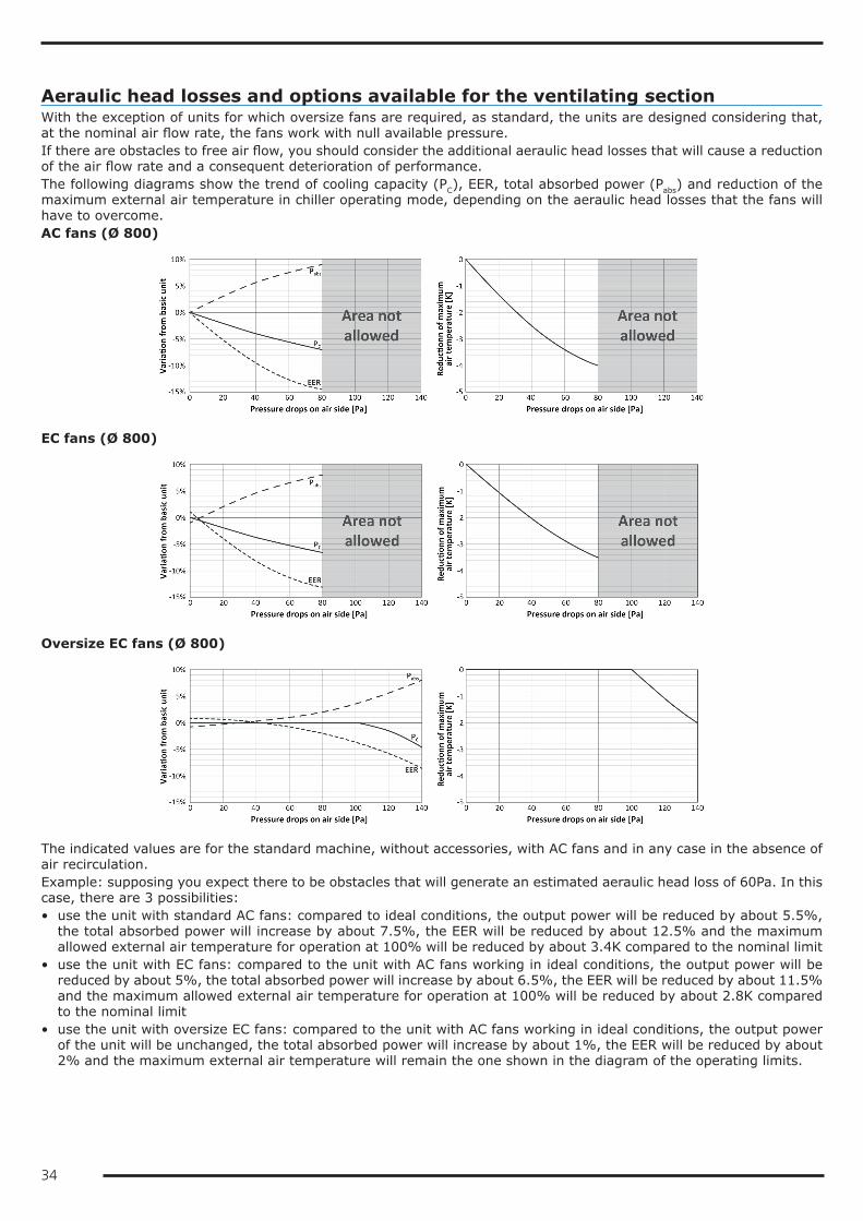
34
Aeraulic head losses and options available for the ventilating sectionWith the exception of units for which oversize fans are required, as standard, the units are designed considering that, at the nominal air flow rate, the fans work with null available pressure.If there are obstacles to free air flow, you should consider the additional aeraulic head losses that will cause a reduction of the air flow rate and a consequent deterioration of performance.The following diagrams show the trend of cooling capacity (PC), EER, total absorbed power (Pabs) and reduction of the maximum external air temperature in chiller operating mode, depending on the aeraulic head losses that the fans will have to overcome.AC fans (Ø 800)
EC fans (Ø 800)
Oversize EC fans (Ø 800)
The indicated values are for the standard machine, without accessories, with AC fans and in any case in the absence of air recirculation.Example: supposing you expect there to be obstacles that will generate an estimated aeraulic head loss of 60Pa. In this case, there are 3 possibilities:• use the unit with standard AC fans: compared to ideal conditions, the output power will be reduced by about 5.5%,
the total absorbed power will increase by about 7.5%, the EER will be reduced by about 12.5% and the maximum allowed external air temperature for operation at 100% will be reduced by about 3.4K compared to the nominal limit
• use the unit with EC fans: compared to the unit with AC fans working in ideal conditions, the output power will be reduced by about 5%, the total absorbed power will increase by about 6.5%, the EER will be reduced by about 11.5% and the maximum allowed external air temperature for operation at 100% will be reduced by about 2.8K compared to the nominal limit
• use the unit with oversize EC fans: compared to the unit with AC fans working in ideal conditions, the output power of the unit will be unchanged, the total absorbed power will increase by about 1%, the EER will be reduced by about 2% and the maximum external air temperature will remain the one shown in the diagram of the operating limits.

35
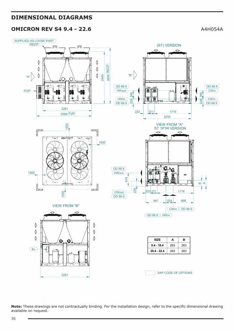
36
DIMENSIONAL DIAGRAMS
OMICRON REV S4 9.4 - 22.6 A4H054A
(ST) VERSION
1500
1500
1500
1500
"A"
2250
VIEW FROM "A" ST 1P1R VERSION
223 311 1716
229
390
2440
2291
968334947A
619
229
229
390
223 311 1716
CWin
CWinHWout
HWin
HWout
CWout
HWin
CWin
OD 88.9
OD 88.9
OD 88.9
OD 88.9
OD 88.9
OD 88.9 OD 88.9
OD 88.9
VIEW FROM "B"
Es
2291
"B"
B
SIZE A B
9.4 - 18.4 263 263
20.4 - 22.4 283 263
2580
FVP
FVP
SAP CODE OF OPTIONS
2620
REC
P
RECPSUPPLIED AS LOOSE PART
Note: These drawings are not contractually binding. For the installation design, refer to the specific dimensional drawing available on request.
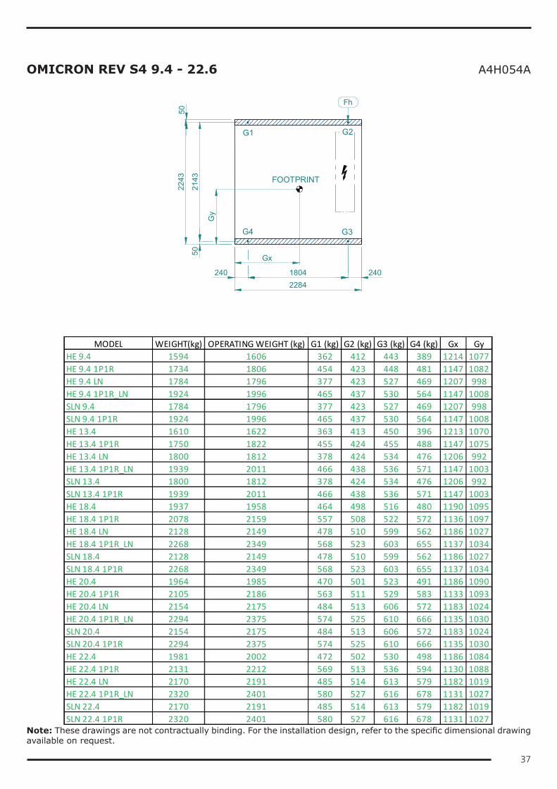
37
OMICRON REV S4 9.4 - 22.6 A4H054A
FOOTPRINT
G1 G2
G4 G3
240 1804 240
5021
43
5022
43
2284
Fh
Gx
Gy
MODEL WEIGHT(kg) OPERATING WEIGHT (kg) G1 (kg) G2 (kg) G3 (kg) G4 (kg) Gx GyHE 9.4 1594 1606 362 412 443 389 1214 1077HE 9.4 1P1R 1734 1806 454 423 448 481 1147 1082HE 9.4 LN 1784 1796 377 423 527 469 1207 998HE 9.4 1P1R_LN 1924 1996 465 437 530 564 1147 1008SLN 9.4 1784 1796 377 423 527 469 1207 998SLN 9.4 1P1R 1924 1996 465 437 530 564 1147 1008HE 13.4 1610 1622 363 413 450 396 1213 1070HE 13.4 1P1R 1750 1822 455 424 455 488 1147 1075HE 13.4 LN 1800 1812 378 424 534 476 1206 992HE 13.4 1P1R_LN 1939 2011 466 438 536 571 1147 1003SLN 13.4 1800 1812 378 424 534 476 1206 992SLN 13.4 1P1R 1939 2011 466 438 536 571 1147 1003HE 18.4 1937 1958 464 498 516 480 1190 1095HE 18.4 1P1R 2078 2159 557 508 522 572 1136 1097HE 18.4 LN 2128 2149 478 510 599 562 1186 1027HE 18.4 1P1R_LN 2268 2349 568 523 603 655 1137 1034SLN 18.4 2128 2149 478 510 599 562 1186 1027SLN 18.4 1P1R 2268 2349 568 523 603 655 1137 1034HE 20.4 1964 1985 470 501 523 491 1186 1090HE 20.4 1P1R 2105 2186 563 511 529 583 1133 1093HE 20.4 LN 2154 2175 484 513 606 572 1183 1024HE 20.4 1P1R_LN 2294 2375 574 525 610 666 1135 1030SLN 20.4 2154 2175 484 513 606 572 1183 1024SLN 20.4 1P1R 2294 2375 574 525 610 666 1135 1030HE 22.4 1981 2002 472 502 530 498 1186 1084HE 22.4 1P1R 2131 2212 569 513 536 594 1130 1088HE 22.4 LN 2170 2191 485 514 613 579 1182 1019HE 22.4 1P1R_LN 2320 2401 580 527 616 678 1131 1027SLN 22.4 2170 2191 485 514 613 579 1182 1019SLN 22.4 1P1R 2320 2401 580 527 616 678 1131 1027
Note: These drawings are not contractually binding. For the installation design, refer to the specific dimensional drawing available on request.
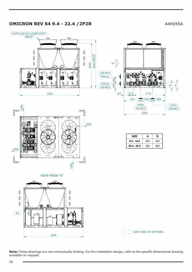
38
OMICRON REV S4 9.4 - 22.4 /2P2R A4H055A15
00
1500
1500
1500
2250
223 311 1716
229
390
2440
3246
CWinHWin
HWout
CWoutOD 88.9
OD 88.9
OD 88.9 OD 88.9
VIEW FROM "A"
Es
3246
"A"
916 638 695
B A
SIZE A B
9.4 - 18.4 263 263
20.4 - 22.4 283 263
2620
REC
P
RECPSUPPLIED AS LOOSE PART
SAP CODE OF OPTIONS
Note: These drawings are not contractually binding. For the installation design, refer to the specific dimensional drawing available on request.
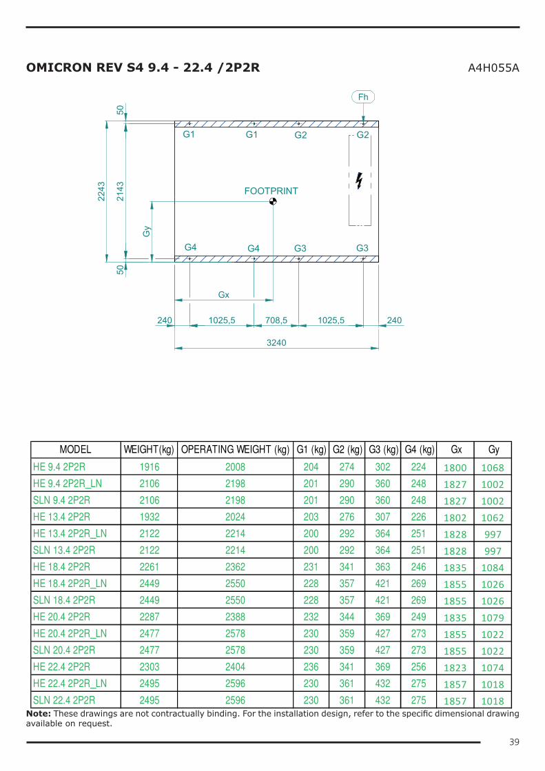
39
OMICRON REV S4 9.4 - 22.4 /2P2R A4H055A
FOOTPRINT
G1 G2
G4 G3
G1
G4
G2
G3
5021
4350
2243
240 1025,5 240
3240
708,5 1025,5
Fh
Gx
Gy
MODEL WEIGHT(kg) OPERATING WEIGHT (kg) G1 (kg) G2 (kg) G3 (kg) G4 (kg) Gx Gy
HE 9.4 2P2R 1916 2008 204 274 302 224 1800 1068HE 9.4 2P2R_LN 2106 2198 201 290 360 248 1827 1002SLN 9.4 2P2R 2106 2198 201 290 360 248 1827 1002HE 13.4 2P2R 1932 2024 203 276 307 226 1802 1062HE 13.4 2P2R_LN 2122 2214 200 292 364 251 1828 997SLN 13.4 2P2R 2122 2214 200 292 364 251 1828 997HE 18.4 2P2R 2261 2362 231 341 363 246 1835 1084HE 18.4 2P2R_LN 2449 2550 228 357 421 269 1855 1026SLN 18.4 2P2R 2449 2550 228 357 421 269 1855 1026HE 20.4 2P2R 2287 2388 232 344 369 249 1835 1079HE 20.4 2P2R_LN 2477 2578 230 359 427 273 1855 1022SLN 20.4 2P2R 2477 2578 230 359 427 273 1855 1022HE 22.4 2P2R 2303 2404 236 341 369 256 1823 1074HE 22.4 2P2R_LN 2495 2596 230 361 432 275 1857 1018SLN 22.4 2P2R 2495 2596 230 361 432 275 1857 1018
Note: These drawings are not contractually binding. For the installation design, refer to the specific dimensional drawing available on request.
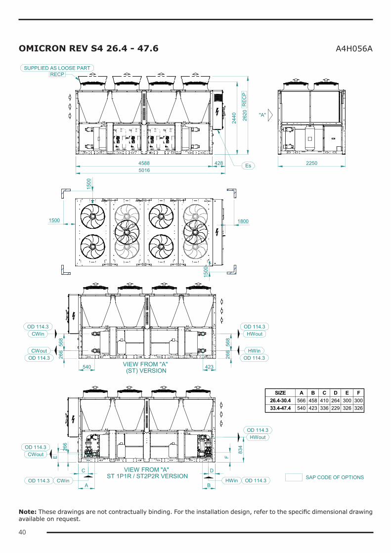
40
OMICRON REV S4 26.4 - 47.6 A4H056A
VIEW FROM "A" (ST) VERSION
VIEW FROM "A" ST 1P1R / ST2P2R VERSION
1800
1500
1500
1500
4588 428
2440 "A"
22505016
540 423
266
568
266
568
C D
F
CWout
CWin
HWin
HWout
Es
HWin
HWout
834
CWout
266
E
CWinBA
OD 114.3
OD 114.3
OD 114.3
OD 114.3
OD 114.3
OD 114.3
OD 114.3
OD 114.3
SIZE A B C D E F26.4-30.4 566 458 410 264 300 30033.4-47.4 540 423 336 229 326 326
2620
RECPSUPPLIED AS LOOSE PART
REC
P
SAP CODE OF OPTIONS
Note: These drawings are not contractually binding. For the installation design, refer to the specific dimensional drawing available on request.
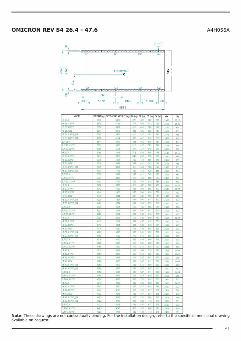
41
OMICRON REV S4 26.4 - 47.6 A4H056A
G1 G1 G2 G2
G4 G4 G3 G3
FOOTPRINT
330 1572 1349 1000 330
4581
5021
4350
2243
Fh
Gx
Gy
MODEL WEIGHT(kg) OPERATING WEIGHT (kg) G1 (kg) G2 (kg) G3 (kg) G4 (kg) Gx GyHE 26.4 3440 3496 376 422 502 448 2511 1015HE 26.4 1P1R 3670 3766 379 493 572 439 2596 1026HE 26.4 2P2R 3892 3978 418 443 580 548 2474 968HE 26.4 LN 3614 3670 385 425 538 487 2500 983HE 26.4 1P1R_LN 3864 3950 410 437 582 546 2478 959HE 26.4 2P2R_LN 4068 4154 427 447 615 588 2466 942SLN 26.4 3614 3670 385 425 538 487 2500 983SLN 26.4 1P1R 3864 3950 410 437 582 546 2478 959SLN 26.4 2P2R 4068 4154 427 447 615 588 2466 942HE 30.4 3465 3524 378 428 508 448 2516 1016HE 30.4 1P1R 3713 3802 403 439 552 507 2492 989HE 30.4 2P2R 3915 4004 420 449 585 548 2478 969HE 30.4 LN 3639 3698 387 431 543 488 2505 985HE 30.4 1P1R_LN 3891 3980 412 443 588 547 2483 961HE 30.4 2P2R_LN 4091 4180 429 453 620 588 2471 943SLN 30.4 3639 3698 387 431 543 488 2505 985SLN 30.4 1P1R 3891 3980 412 443 588 547 2483 961SLN 30.4 2P2R 4091 4180 429 453 620 588 2471 943HE 33.4 3792 3866 412 482 560 479 2538 1026HE 33.4 1P1R 4042 4146 438 493 605 537 2514 1000HE 33.4 2P2R 4246 4350 455 503 639 578 2501 982HE 33.4 LN 3970 4044 422 486 596 518 2527 996HE 33.4 1P1R_LN 4220 4324 447 497 641 577 2505 973HE 33.4 2P2R_LN 4420 4524 464 506 674 618 2493 957SLN 33.4 3970 4044 422 486 596 518 2527 996SLN 33.4 1P1R 4220 4324 447 497 641 577 2505 973SLN 33.4 2P2R 4420 4524 464 506 674 618 2493 957HE 37.4 3838 3912 416 485 568 487 2535 1022HE 37.4 1P1R 4110 4214 444 497 616 550 2511 995HE 37.4 2P2R 4310 4414 461 506 649 591 2498 977HE 37.4 LN 4016 4090 426 489 604 526 2525 993HE 37.4 1P1R_LN 4286 4390 453 501 652 589 2502 969HE 37.4 2P2R_LN 4486 4590 470 510 685 630 2490 953SLN 37.4 4016 4090 426 489 604 526 2525 993SLN 37.4 1P1R 4286 4390 453 501 652 589 2502 969SLN 37.4 2P2R 4486 4590 470 510 685 630 2490 953HE 42.4 3910 3996 429 504 575 490 2538 1033HE 42.4 1P1R 4184 4300 457 516 624 553 2514 1006HE 42.4 2P2R 4382 4498 474 525 657 593 2501 988HE 42.4 LN 4086 4172 439 507 611 529 2528 1004HE 42.4 1P1R_LN 4356 4472 466 519 659 592 2505 980HE 42.4 2P2R_LN 4556 4672 483 528 692 633 2493 963SLN 42.4 4086 4172 439 507 611 529 2528 1004SLN 42.4 1P1R 4356 4472 466 519 659 592 2505 980SLN 42.4 2P2R 4556 4672 483 528 692 633 2493 963HE 47.4 3970 4056 432 505 588 503 2535 1023HE 47.4 1P1R 4247 4370 456 517 644 568 2517 991HE 47.4 2P2R 4447 4570 473 526 677 609 2504 974HE 47.4 LN 4133 4216 436 507 627 538 2531 992HE 47.4 1P1R_LN 4423 4546 465 521 680 607 2508 966HE 47.4 2P2R_LN 4623 4746 482 530 713 648 2496 951SLN 47.4 4133 4216 436 507 627 538 2531 992SLN 47.4 1P1R 4423 4546 465 521 680 607 2508 966SLN 47.4 2P2R 4623 4746 482 530 713 648 2496 951
Note: These drawings are not contractually binding. For the installation design, refer to the specific dimensional drawing available on request.
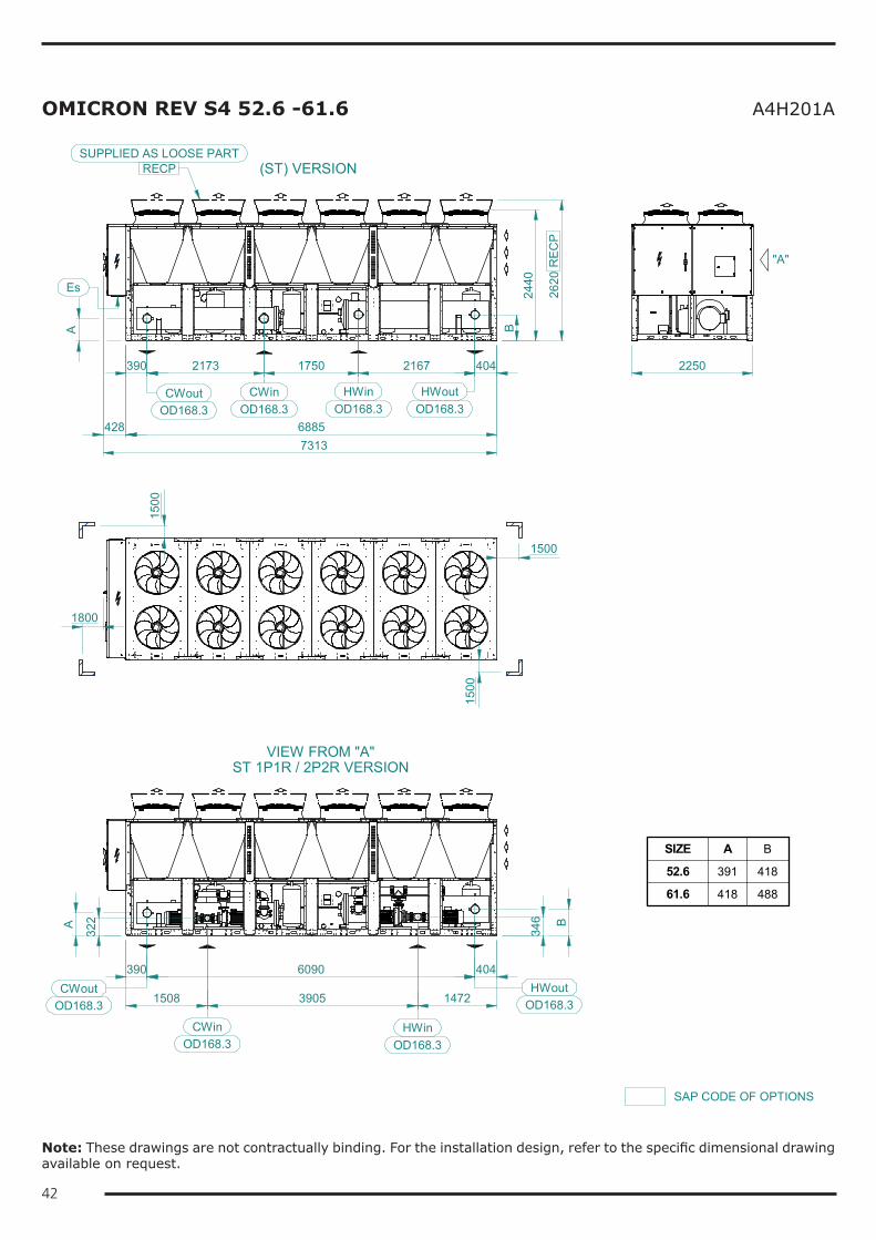
42
OMICRON REV S4 52.6 -61.6 A4H201A
(ST) VERSION
428 6885
390 2173 1750 2167 404
7313
2250
"A"
1500
1500
1500
1800
VIEW FROM "A"ST 1P1R / 2P2R VERSION
CWout CWin HWoutHWinOD168.3 OD168.3 OD168.3 OD168.3
390
1508 3905 1472
6090 404
BA
CWoutOD168.3
CWinOD168.3
HWin
HWoutOD168.3
OD168.3
A
322
346 B
2440
2620
REC
P
SIZE A B
52.6 391 418
61.6 418 488
Es
RECPSUPPLIED AS LOOSE PART
SAP CODE OF OPTIONS
Note: These drawings are not contractually binding. For the installation design, refer to the specific dimensional drawing available on request.
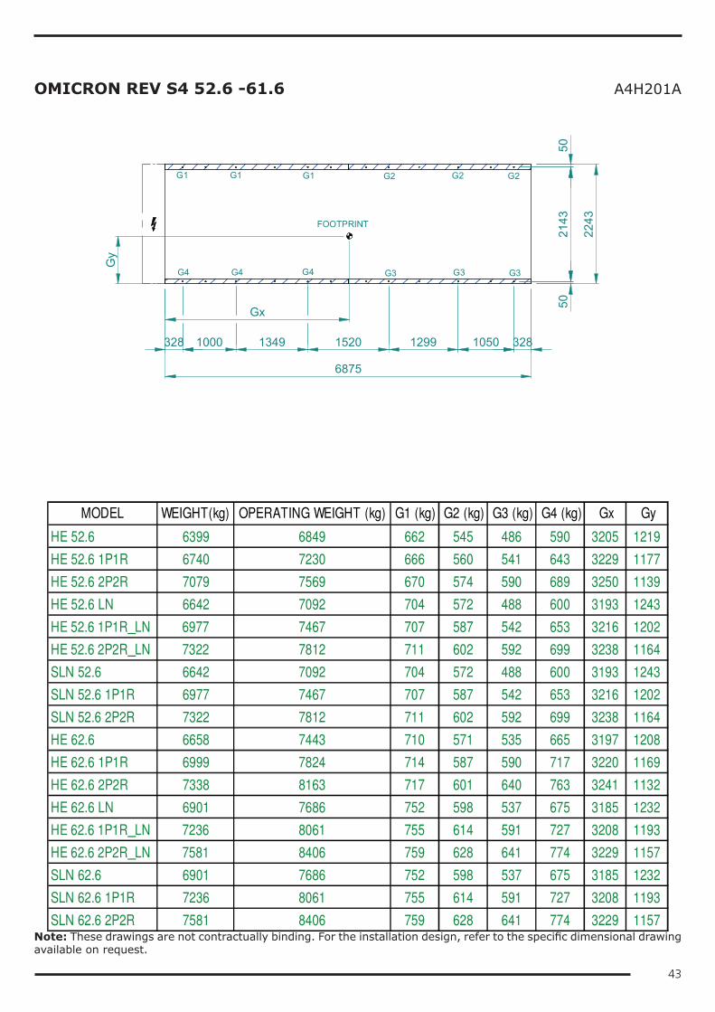
43
OMICRON REV S4 52.6 -61.6 A4H201A
G1 G1 G1 G2 G2
G4 G4 G4 G3 G3
FOOTPRINT
G2
G3
328 1000 1349 1520 1299 328
6875
5021
4350
2243
1050
MODEL WEIGHT(kg) OPERATING WEIGHT (kg) G1 (kg) G2 (kg) G3 (kg) G4 (kg) Gx Gy
HE 52.6 6399 6849 662 545 486 590 3205 1219
HE 52.6 1P1R 6740 7230 666 560 541 643 3229 1177
HE 52.6 2P2R 7079 7569 670 574 590 689 3250 1139
HE 52.6 LN 6642 7092 704 572 488 600 3193 1243
HE 52.6 1P1R_LN 6977 7467 707 587 542 653 3216 1202
HE 52.6 2P2R_LN 7322 7812 711 602 592 699 3238 1164
SLN 52.6 6642 7092 704 572 488 600 3193 1243
SLN 52.6 1P1R 6977 7467 707 587 542 653 3216 1202
SLN 52.6 2P2R 7322 7812 711 602 592 699 3238 1164
HE 62.6 6658 7443 710 571 535 665 3197 1208
HE 62.6 1P1R 6999 7824 714 587 590 717 3220 1169
HE 62.6 2P2R 7338 8163 717 601 640 763 3241 1132
HE 62.6 LN 6901 7686 752 598 537 675 3185 1232
HE 62.6 1P1R_LN 7236 8061 755 614 591 727 3208 1193
HE 62.6 2P2R_LN 7581 8406 759 628 641 774 3229 1157
SLN 62.6 6901 7686 752 598 537 675 3185 1232
SLN 62.6 1P1R 7236 8061 755 614 591 727 3208 1193
SLN 62.6 2P2R 7581 8406 759 628 641 774 3229 1157
Gx
Gy
Note: These drawings are not contractually binding. For the installation design, refer to the specific dimensional drawing available on request.
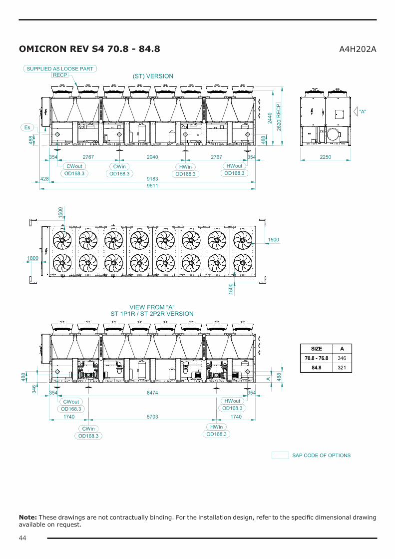
44
OMICRON REV S4 70.8 - 84.8 A4H202A
(ST) VERSION
428 91839611
354
VIEW FROM "A"ST 1P1R / ST 2P2R VERSION
2767 2940 2767 354
488
2440
2620
HWin HWoutCWinCWout
RECPSUPPLIED AS LOOSE PART
1500
1500
1800
1500
2250
OD168.3
354 8474 354
1740 5703 1740
488
A
346
488
SIZE A
70.8 - 76.8 346
84.8 321
OD168.3 OD168.3 OD168.3
SAP CODE OF OPTIONS
Es
488
REC
P
"A"
HWinOD168.3
HWoutOD168.3
CWoutOD168.3
CWinOD168.3
Note: These drawings are not contractually binding. For the installation design, refer to the specific dimensional drawing available on request.
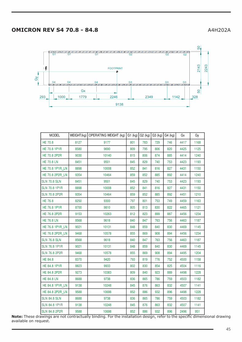
45
OMICRON REV S4 70.8 - 84.8 A4H202A
G1 G1 G2 G2G1 G2
G4 G4 G3 G3G4 G3
FOOTPRINT
293
9138
1000 1779 2246 2349 1142 328
5021
4350
2243
Gx
Gy
MODEL WEIGHT(kg) OPERATING WEIGHT (kg) G1 (kg) G2 (kg) G3 (kg) G4 (kg) Gx Gy
HE 70.8 8127 9177 801 783 729 746 4417 1168
HE 70.8 1P1R 8580 9690 809 795 806 820 4425 1125
HE 70.8 2P2R 9030 10140 815 806 874 885 4414 1240
HE 70.8 LN 8451 9501 845 829 740 753 4423 1193
HE 70.8 1P1R_LN 8898 10008 852 841 816 827 4431 1150
HE 70.8 2P2R_LN 9354 10464 859 852 885 892 4414 1240
SLN 70.8 SLN 8451 9501 845 829 740 753 4423 1193
SLN 70.8 1P1R 8898 10008 852 841 816 827 4431 1150
SLN 70.8 2P2R 9354 10464 859 852 885 892 4451 1210
HE 76.8 8250 9300 797 801 753 749 4459 1163
HE 76.8 1P1R 8700 9810 805 813 830 822 4465 1121
HE 76.8 2P2R 9153 10263 812 823 899 887 4456 1234
HE 76.8 LN 8568 9618 840 847 763 756 4463 1187
HE 76.8 1P1R_LN 9021 10131 848 859 840 830 4469 1145
HE 76.8 2P2R_LN 9468 10578 855 869 908 894 4456 1234
SLN 76.8 SLN 8568 9618 840 847 763 756 4463 1187
SLN 76.8 1P1R 9021 10131 848 859 840 830 4469 1145
SLN 76.8 2P2R 9468 10578 855 869 908 894 4495 1204
HE 84.8 8370 9420 793 819 776 752 4500 1158
HE 84.8 1P1R 8823 9933 802 830 854 825 4504 1116
HE 84.8 2P2R 9273 10383 809 840 923 889 4498 1228
HE 84.8 LN 8688 9738 836 865 786 759 4503 1182
HE 84.8 1P1R_LN 9138 10248 845 876 863 832 4507 1141
HE 84.8 2P2R_LN 9588 10698 852 886 932 896 4498 1228
SLN 84.8 SLN 8688 9738 836 865 786 759 4503 1182
SLN 84.8 1P1R 9138 10248 845 876 863 832 4507 1141
SLN 84.8 2P2R 9588 10698 852 886 932 896 2496 951
Note: These drawings are not contractually binding. For the installation design, refer to the specific dimensional drawing available on request.