omicron test universe - measurement package v 2gemtaelektronik.com.tr/uploads/documents/1128.pdf ·...
TRANSCRIPT

MeasurementP A C K A G E User Manual
OMICRON Test Universe
2
Article Number VESD4004 - Manual Version: MEAS.AE.10
© OMICRON electronics 2008. All rights reserved.
This manual is a publication of OMICRON electronics GmbH.
All rights including translation reserved. Reproduction of any kind, e.g., photocopying, microfilming, optical character recognition and/or storage in electronic data processing systems, requires the explicit consent of OMICRON electronics.
Reprinting, wholly or in part, is not permitted.The product information, specifications, and technical data embodied in this manual represent the technical status at the time of writing and are subject to change without prior notice.
We have done our best to ensure that the information given in this manual is useful, accurate and entirely reliable. However, OMICRON electronics does not assume responsibility for any inaccuracies which may be present.
The user is responsible for every application that makes use of an OMICRON product.
OMICRON electronics translates this manual from the source language English into a number of other languages. Any translation of this manual is done for local requirements, and in the event of a dispute between the English and a non-English version, the English version of this manual shall govern.
Table of Contents
3
Table of Contents
Introduction . . . . . . . . . . . . . . . . . . . . . . . . . . . . . . . . . . . . . . . . . . . . . . . . . . .7Preface . . . . . . . . . . . . . . . . . . . . . . . . . . . . . . . . . . . . . . . . . . . . . . . . .8Scope of Measurement . . . . . . . . . . . . . . . . . . . . . . . . . . . . . . . . . . . . .9
1 QuickCMC. . . . . . . . . . . . . . . . . . . . . . . . . . . . . . . . . . . . . . . . . . . . . . . . . . . .131.1 QuickCMC Features . . . . . . . . . . . . . . . . . . . . . . . . . . . . . . . . . . . . . . . .14
1.2 QuickCMC Example: Frequency Trip Contact of a Multifunctional Transducer. . . . . . . . . . . . .151.2.1 Connecting a Transducer to the CMC Test Set . . . . . . . . . . . . .161.2.2 Starting QuickCMC. . . . . . . . . . . . . . . . . . . . . . . . . . . . . . . . . . .161.2.3 Configuring the Hardware. . . . . . . . . . . . . . . . . . . . . . . . . . . . . .161.2.4 Defining the Test. . . . . . . . . . . . . . . . . . . . . . . . . . . . . . . . . . . . .16
2 Meter . . . . . . . . . . . . . . . . . . . . . . . . . . . . . . . . . . . . . . . . . . . . . . . . . . . . . . . .212.1 About Meter . . . . . . . . . . . . . . . . . . . . . . . . . . . . . . . . . . . . . . . . . . . . . . .21
2.2 Time Sequence of a Meter Test . . . . . . . . . . . . . . . . . . . . . . . . . . . . . . .222.3 Meter Example 1: Testing a Static CT/PT-Operated Meter. . . . . . . . . . .24
2.3.1 Considerations Prior to the Test: . . . . . . . . . . . . . . . . . . . . . . . .252.3.2 Test Setup . . . . . . . . . . . . . . . . . . . . . . . . . . . . . . . . . . . . . . . . .252.3.3 Starting Meter in Stand-alone Mode . . . . . . . . . . . . . . . . . . . . . .262.3.4 Setting up the Test Object . . . . . . . . . . . . . . . . . . . . . . . . . . . . .262.3.5 Configuring the Hardware. . . . . . . . . . . . . . . . . . . . . . . . . . . . . .262.3.6 Defining the Test. . . . . . . . . . . . . . . . . . . . . . . . . . . . . . . . . . . . .272.3.7 Defining the Test Report. . . . . . . . . . . . . . . . . . . . . . . . . . . . . . .352.3.8 Saving the Test Report . . . . . . . . . . . . . . . . . . . . . . . . . . . . . . . .35
OMICRON Test Universe
4
2.4 Meter Example 2: Testing an Electromechanical Meter . . . . . . . . . . . . .362.4.1 Considerations Prior to the Test . . . . . . . . . . . . . . . . . . . . . . . . .372.4.2 Test Setup . . . . . . . . . . . . . . . . . . . . . . . . . . . . . . . . . . . . . . . . .382.4.3 Starting Meter in Stand-alone Mode . . . . . . . . . . . . . . . . . . . . . .392.4.4 Setting up the Test Object . . . . . . . . . . . . . . . . . . . . . . . . . . . . .392.4.5 Configuring the Hardware. . . . . . . . . . . . . . . . . . . . . . . . . . . . . .392.4.6 Defining the Test Steps . . . . . . . . . . . . . . . . . . . . . . . . . . . . . . .402.4.7 Defining the Test Report. . . . . . . . . . . . . . . . . . . . . . . . . . . . . . .512.4.8 Saving the Test Report . . . . . . . . . . . . . . . . . . . . . . . . . . . . . . . .52
2.5 Meter Example 3: Testing a Multifunctional Electronical Meter. . . . . . . .532.5.1 Considerations Prior to the Test . . . . . . . . . . . . . . . . . . . . . . . . .542.5.2 Test Setup . . . . . . . . . . . . . . . . . . . . . . . . . . . . . . . . . . . . . . . . .552.5.3 Starting Meter in Stand-alone Mode . . . . . . . . . . . . . . . . . . . . . .552.5.4 Setting up the Test Object . . . . . . . . . . . . . . . . . . . . . . . . . . . . .552.5.5 Configuring the Hardware. . . . . . . . . . . . . . . . . . . . . . . . . . . . . .562.5.6 Defining the Test. . . . . . . . . . . . . . . . . . . . . . . . . . . . . . . . . . . . .572.5.7 Defining the Test Report. . . . . . . . . . . . . . . . . . . . . . . . . . . . . . .662.5.8 Saving the Test Report . . . . . . . . . . . . . . . . . . . . . . . . . . . . . . . .67
3 Transducer . . . . . . . . . . . . . . . . . . . . . . . . . . . . . . . . . . . . . . . . . . . . . . . . . . .693.1 About Transducer . . . . . . . . . . . . . . . . . . . . . . . . . . . . . . . . . . . . . . . . . .693.2 Transducers and Multifunctional Transducers. . . . . . . . . . . . . . . . . . . . .71
3.3 Transducer example: Active Power Transducer . . . . . . . . . . . . . . . . . . .733.3.1 Connecting a Transducer to the CMC Test Set . . . . . . . . . . . . .743.3.2 Starting Transducer . . . . . . . . . . . . . . . . . . . . . . . . . . . . . . . . . .753.3.3 Setting up the Test Object . . . . . . . . . . . . . . . . . . . . . . . . . . . . .753.3.4 Configuring the Hardware. . . . . . . . . . . . . . . . . . . . . . . . . . . . . .753.3.5 Performing a Manual Calibration Test . . . . . . . . . . . . . . . . . . . .763.3.6 Defining an Automatic Test. . . . . . . . . . . . . . . . . . . . . . . . . . . . .783.3.7 Defining the Test Report Format . . . . . . . . . . . . . . . . . . . . . . . .793.3.8 Running a Test . . . . . . . . . . . . . . . . . . . . . . . . . . . . . . . . . . . . . .80
5
Table of Contents
4 CMEngine . . . . . . . . . . . . . . . . . . . . . . . . . . . . . . . . . . . . . . . . . . . . . . . . . . . .83
5 Test Tools . . . . . . . . . . . . . . . . . . . . . . . . . . . . . . . . . . . . . . . . . . . . . . . . . . . .855.1 TransPlay . . . . . . . . . . . . . . . . . . . . . . . . . . . . . . . . . . . . . . . . . . . . . . . .85
5.1.1 TransPlay Features . . . . . . . . . . . . . . . . . . . . . . . . . . . . . . . . . .855.1.2 TransPlay Example. . . . . . . . . . . . . . . . . . . . . . . . . . . . . . . . . . .86
5.2 Harmonics . . . . . . . . . . . . . . . . . . . . . . . . . . . . . . . . . . . . . . . . . . . . . . . .98
5.3 Binary I/O Monitor . . . . . . . . . . . . . . . . . . . . . . . . . . . . . . . . . . . . . . . . . .995.3.1 Features of the Binary I/O Monitor . . . . . . . . . . . . . . . . . . . . . .1005.3.2 Using Binary I/O Monitor. . . . . . . . . . . . . . . . . . . . . . . . . . . . . .1005.3.3 Context Menu . . . . . . . . . . . . . . . . . . . . . . . . . . . . . . . . . . . . . .1015.3.4 Options Menu . . . . . . . . . . . . . . . . . . . . . . . . . . . . . . . . . . . . . .102
5.4 Polarity Checker . . . . . . . . . . . . . . . . . . . . . . . . . . . . . . . . . . . . . . . . . .103
5.5 AuxDC . . . . . . . . . . . . . . . . . . . . . . . . . . . . . . . . . . . . . . . . . . . . . . . . . .104
5.6 License Manager . . . . . . . . . . . . . . . . . . . . . . . . . . . . . . . . . . . . . . . . . .1065.6.1 About License Files in General. . . . . . . . . . . . . . . . . . . . . . . . .1065.6.2 Finding License Files . . . . . . . . . . . . . . . . . . . . . . . . . . . . . . . .1065.6.3 Contents of a License File . . . . . . . . . . . . . . . . . . . . . . . . . . . .1075.6.4 Merging License Files into the Master License File . . . . . . . . .1075.6.5 Merging Single Devices and Keys Into the Master License File. . .
1085.6.6 Context Menus . . . . . . . . . . . . . . . . . . . . . . . . . . . . . . . . . . . . .1085.6.7 Sorting the Displayed Data . . . . . . . . . . . . . . . . . . . . . . . . . . . .1085.6.8 Show Only Licenses With Version . . . . . . . . . . . . . . . . . . . . . .1095.6.9 Sending Your Master License File to OMICRON by E-Mail . . .109
File Name Extensions within OMICRON Test Universe . . . . . . . . . . . . . .111
Contact Information / Technical Support . . . . . . . . . . . . . . . . . . . . . . . . .115
Index . . . . . . . . . . . . . . . . . . . . . . . . . . . . . . . . . . . . . . . . . . . . . . . . . . . . . . .117

OMICRON Test Universe
6
Introduction
7
IntroductionThe Measurement manual describes application areas for measurement technology and contains information and - where applicable - examples for the test modules and test tools.
Measurement’s test modules are suitable for handling various hardware configurations, as shown in their examples.
Refer to the associated hardware manuals for detailed information about the hardware employed.
A comprehensive online help system is available for the OMCRON Test Universe. The help files explain in detail the entire functionality of the OMICRON Control Center (OCC), the hardware configuration, and of all test modules and test tools.
The provided examples describe typical applications. However, the examples can only show a small part of the wide spectrum of the possible application areas where the OMICRON Test Universe can be employed.
This manual is intended to guide the initial steps in using the equipment and to serve as a reference for later. Therefore, it is recommended that it be present during on-site tests.
OMICRON Test Universe
8
PrefaceWe assume that you understand and are comfortable using the Windows™ operating system1. Please take time to become familiar with your computer's operating system before using OMICRON Test Universe.
This manual uses the following conventions:
MouseClick Press and release the primary mouse button. The primary
mouse button is the button you use most often. For most people, this is the left mouse button.
Right-click Press and release the secondary mouse button. The secondary button is the button you use least often. For most people, this is the right button.
Double-click Press and release the primary mouse button twice.
Drag Move the mouse while you hold down the primary mouse button.
Release Remove your finger from a mouse button.
Scroll Scroll bars along the right and bottom sides of a window can be used to move the contents up and down and left and right within the window. To use a scrollbar, either click and hold one of the arrow buttons at either end of the bar, or drag the scroll bar slider.
1. Windows is a US registered trademark of Microsoft Corporation.
9
Introduction
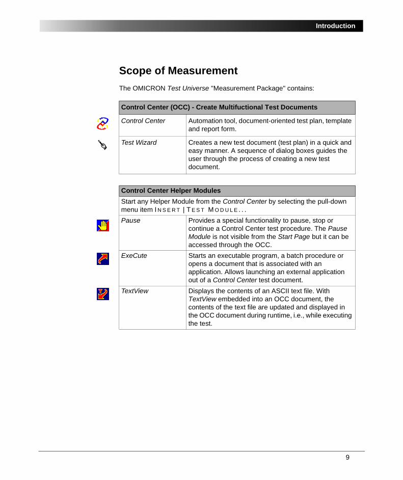
Scope of MeasurementThe OMICRON Test Universe "Measurement Package" contains:
Control Center (OCC) - Create Multifuctional Test Documents
Control Center Automation tool, document-oriented test plan, template and report form.
Test Wizard Creates a new test document (test plan) in a quick and easy manner. A sequence of dialog boxes guides the user through the process of creating a new test document.
Control Center Helper ModulesStart any Helper Module from the Control Center by selecting the pull-down menu item I N S E R T | T E S T M O D U L E . . . Pause Provides a special functionality to pause, stop or
continue a Control Center test procedure. The Pause Module is not visible from the Start Page but it can be accessed through the OCC.
ExeCute Starts an executable program, a batch procedure or opens a document that is associated with an application. Allows launching an external application out of a Control Center test document.
TextView Displays the contents of an ASCII text file. With TextView embedded into an OCC document, the contents of the text file are updated and displayed in the OCC document during runtime, i.e., while executing the test.
OMICRON Test Universe
10
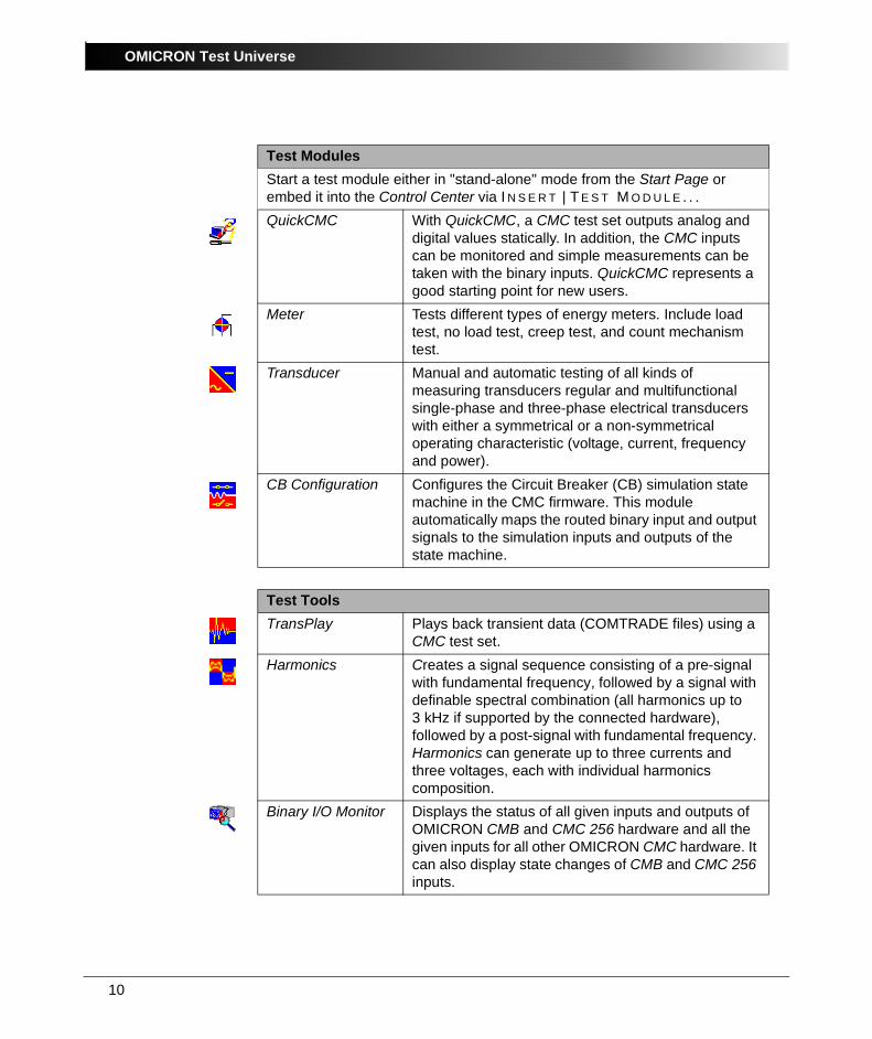
Test ModulesStart a test module either in "stand-alone" mode from the Start Page or embed it into the Control Center via I N S E R T | T E S T M O D U L E . . . QuickCMC With QuickCMC, a CMC test set outputs analog and
digital values statically. In addition, the CMC inputs can be monitored and simple measurements can be taken with the binary inputs. QuickCMC represents a good starting point for new users.
Meter Tests different types of energy meters. Include load test, no load test, creep test, and count mechanism test.
Transducer Manual and automatic testing of all kinds of measuring transducers regular and multifunctional single-phase and three-phase electrical transducers with either a symmetrical or a non-symmetrical operating characteristic (voltage, current, frequency and power).
CB Configuration Configures the Circuit Breaker (CB) simulation state machine in the CMC firmware. This module automatically maps the routed binary input and output signals to the simulation inputs and outputs of the state machine.
Test ToolsTransPlay Plays back transient data (COMTRADE files) using a
CMC test set.Harmonics Creates a signal sequence consisting of a pre-signal
with fundamental frequency, followed by a signal with definable spectral combination (all harmonics up to 3 kHz if supported by the connected hardware), followed by a post-signal with fundamental frequency. Harmonics can generate up to three currents and three voltages, each with individual harmonics composition.
Binary I/O Monitor Displays the status of all given inputs and outputs of OMICRON CMB and CMC 256 hardware and all the given inputs for all other OMICRON CMC hardware. It can also display state changes of CMB and CMC 256 inputs.
11
Introduction
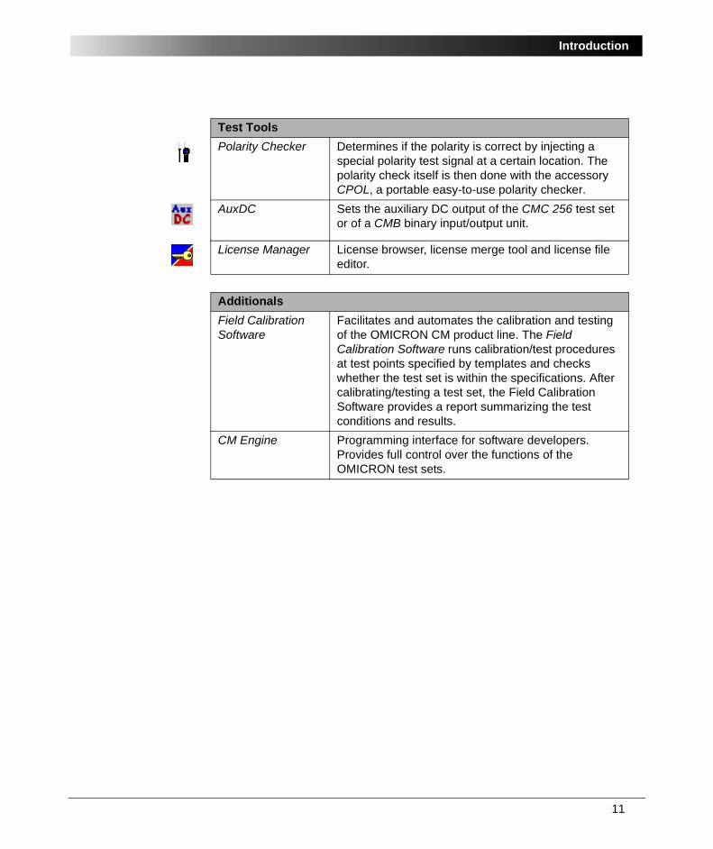
Polarity Checker Determines if the polarity is correct by injecting a special polarity test signal at a certain location. The polarity check itself is then done with the accessory CPOL, a portable easy-to-use polarity checker.
AuxDC Sets the auxiliary DC output of the CMC 256 test set or of a CMB binary input/output unit.
License Manager License browser, license merge tool and license file editor.
AdditionalsField Calibration Software
Facilitates and automates the calibration and testing of the OMICRON CM product line. The Field Calibration Software runs calibration/test procedures at test points specified by templates and checks whether the test set is within the specifications. After calibrating/testing a test set, the Field Calibration Software provides a report summarizing the test conditions and results.
CM Engine Programming interface for software developers. Provides full control over the functions of the OMICRON test sets.
Test Tools

OMICRON Test Universe
12
13
QuickCMC
1 QuickCMCQuickCMC controls an OMICRON CMC test set in the way a front panel control would do.
You can output voltages, currents and frequencies statically or as ramped output signals, work with binary (digital) outputs and inputs and take simple measurements at the anlog inputs. Applications such as the manual testing of an inrush blocking or a synchronizer function can be done with QuickCMC. It is not necessary to start other modules like Ramping or State Sequencer to perform quick manual checks.
There is no upper limit regarding the number of outputs (generators) that can be controlled. In order to test a busbar protection, for example, a CMC 256 test set and two CMA 156 amplifiers are connected. QuickCMC allows the simultaneous control of all 16 generators.
QuickCMC represents a good starting point for new users.
QuickCMC can be used with the following test equipment:
• CMC 56
• CMC 156
• CMC 151
• CMC 256
• CMC 256plus
OMICRON Test Universe
14
1.1 QuickCMC Features• Numeric or graphic control of analog CMC output values (absolute or relative
to nominal) for up to 16 voltage or current generators in terms of amplitude, phase angle and frequency.
• Integrated fault calculator for 2 or 3 phase networks introducing new set modes of operation (setting of voltage and current generators directly or as impedances, symmetrical components, powers and fault values).
• Manual setting of binary outputs.• Display of measured values at the analog CMC inputs (±20 mA / ±10 VDC).• Manual or automatic stepping of the analog output quantities.• Step Function for all values accessible in the "multifunctional input gid1"
(i.e., powers, impedances, etc.). • Pulse ramp function as valuable enhancement of the step/ramp function.• Control of the step function by mouse wheel.• Measurement of binary input with status and timer, i.e., the first state
transition at any binary input after the last change of an output. Shows slope and time.
• "Switch off on trigger" feature to turn off the analog CMC outputs the moment a trigger signal occurs at the binary input (with defineable delay time).
• "Switch off on time" feature to set the maximum time span that has to elapse before QuickCMC turns off the analog CMC outputs in case no trigger signals occurs.
• "Unit Manager" to switch the units between seconds and cycles, secondary and primary values, absolute and relative.
• "Prefault" button to output a prefault state at the analog CMC outputs, i.e., nominal voltage (U = Unom) and zero current output (I = 0 A).
• "Hold" button to switch from prefault to fault state.• Context menus for a quick setting of values.• Impedance plane for manual tests of distance relays.• Vector diagram to show the specified quantities graphically.• Vectors can be set in the Vector View by dragging with the mouse.• User-defined reports and assessment.• "Add to report" button to add all data and actual values at the time the trigger
signal occurs at a binary input to the test report.
1. For information on the "multifunctional input gid" and the fault calculator check the Test Universeonline help. Go to the index and enter "multifunctional...".
15
QuickCMC
1.2 QuickCMC Example: Frequency Trip Contact of a Multifunctional TransducerSample files:
• QuickCMC-Threshold.qcm
• QuickCMC-Threshold.ohc
Stored at:
...OTU installation path\Test Library\Samples\SW Manual Examples\ Measurement
TaskTo test the pick-up and drop-off value of a multifunctional transducer’ binary trip contact. The transducer used in this example is the SIMEAS 7 KG6000-8AB/KK. The transducer’s pick-up value is set to 49.800Hz and must be verified.
SolutionWith QuickCMC, OMICRON Test Universe offers a dedicated test module to easily and quickly perform manual tests.
QuickCMC offers the advantage that it is simple operate, yet provides the functionality to independently adjust up to 16 voltage or current generators in terms of amplitude, phase angle and frequency, to manually step or automatically ramp or pulse ramp all quantities and to perform simple timing tests. A vector diagram uses a graphical display of the specified quantities. Also a reporting function is incorporated.
QuickCMC is typically used in stand-alone mode, although it can also be used as part of the OMICRON Control Center.
OMICRON Test Universe
16
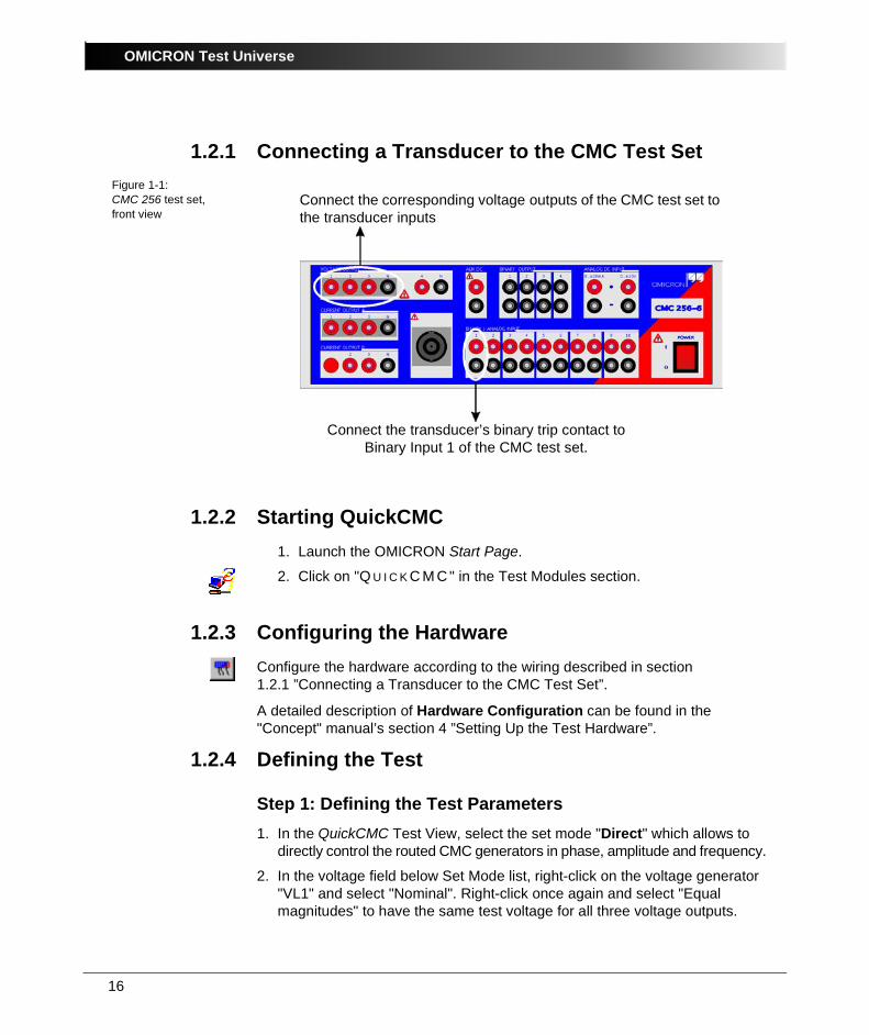
1.2.1 Connecting a Transducer to the CMC Test SetFigure 1-1:CMC 256 test set, front view
1.2.2 Starting QuickCMC1. Launch the OMICRON Start Page.
2. Click on "Q U I C K C M C " in the Test Modules section.
1.2.3 Configuring the HardwareConfigure the hardware according to the wiring described in section 1.2.1 ”Connecting a Transducer to the CMC Test Set”.
A detailed description of Hardware Configuration can be found in the "Concept" manual’s section 4 ”Setting Up the Test Hardware”.
1.2.4 Defining the Test
Step 1: Defining the Test Parameters1. In the QuickCMC Test View, select the set mode "Direct" which allows to
directly control the routed CMC generators in phase, amplitude and frequency.
2. In the voltage field below Set Mode list, right-click on the voltage generator "VL1" and select "Nominal". Right-click once again and select "Equal magnitudes" to have the same test voltage for all three voltage outputs.
Connect the transducer’s binary trip contact to Binary Input 1 of the CMC test set.
Connect the corresponding voltage outputs of the CMC test set to the transducer inputs
17
QuickCMC
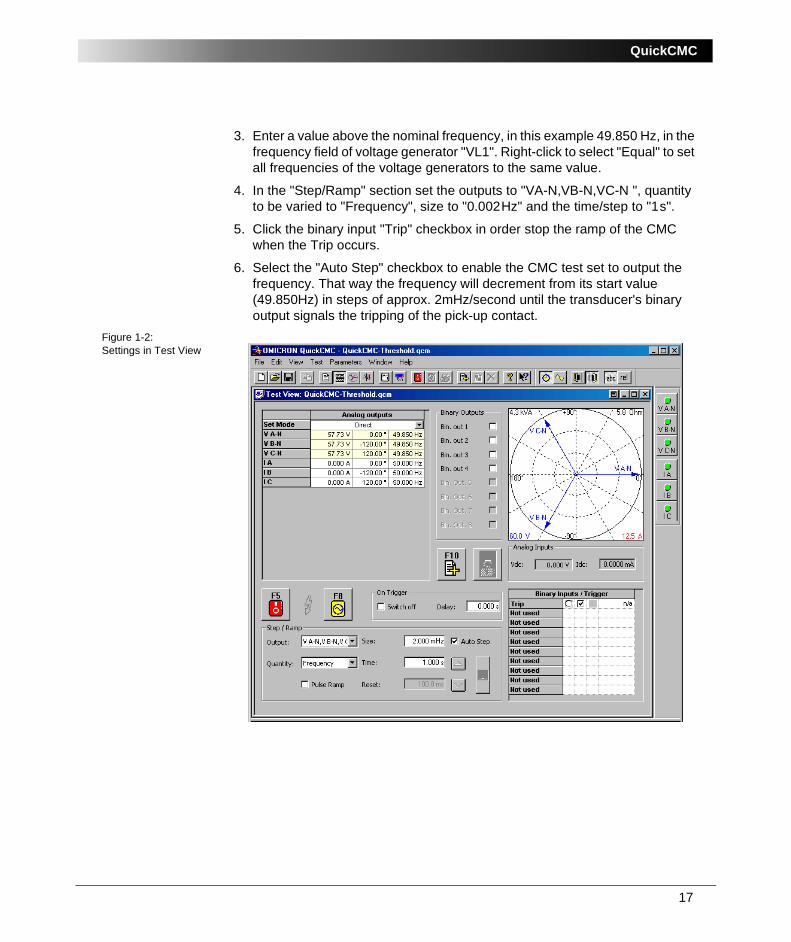
3. Enter a value above the nominal frequency, in this example 49.850 Hz, in the frequency field of voltage generator "VL1". Right-click to select "Equal" to set all frequencies of the voltage generators to the same value.
4. In the "Step/Ramp" section set the outputs to "VA-N,VB-N,VC-N ", quantity to be varied to "Frequency", size to "0.002Hz" and the time/step to "1s".
5. Click the binary input "Trip" checkbox in order stop the ramp of the CMC when the Trip occurs.
6. Select the "Auto Step" checkbox to enable the CMC test set to output the frequency. That way the frequency will decrement from its start value (49.850Hz) in steps of approx. 2mHz/second until the transducer's binary output signals the tripping of the pick-up contact.
Figure 1-2:Settings in Test View
OMICRON Test Universe
18
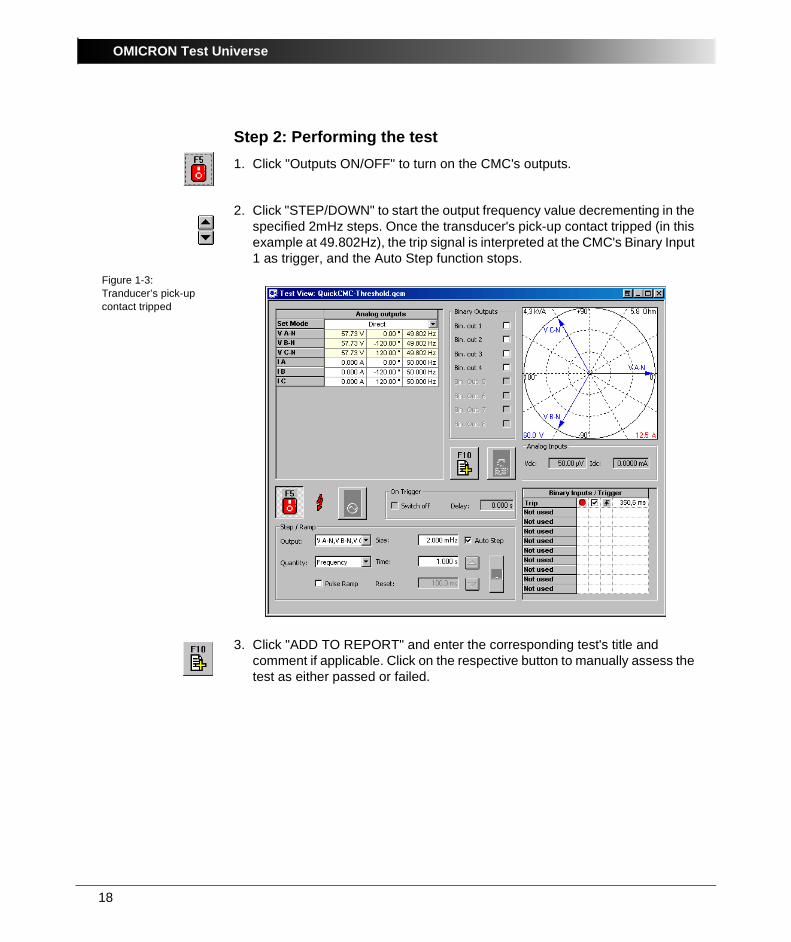
Step 2: Performing the test1. Click "Outputs ON/OFF" to turn on the CMC's outputs.
2. Click "STEP/DOWN" to start the output frequency value decrementing in the specified 2mHz steps. Once the transducer's pick-up contact tripped (in this example at 49.802Hz), the trip signal is interpreted at the CMC's Binary Input 1 as trigger, and the Auto Step function stops.
Figure 1-3:Tranducer’s pick-up contact tripped
3. Click "ADD TO REPORT" and enter the corresponding test's title and comment if applicable. Click on the respective button to manually assess the test as either passed or failed.
19
QuickCMC
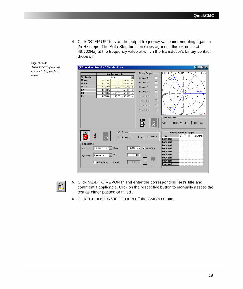
4. Click "STEP UP" to start the output frequency value incrementing again in 2mHz steps. The Auto Step function stops again (in this example at 49.900Hz) at the frequency value at which the transducer's binary contact drops off.
Figure 1-4:Tranducer’s pick-up contact dropped-off again
5. Click "ADD TO REPORT" and enter the corresponding test's title and comment if applicable. Click on the respective button to manually assess the test as either passed or failed .
6. Click "Outputs ON/OFF" to turn off the CMC's outputs.

OMICRON Test Universe
20
21
Meter
2 Meter
2.1 About MeterMeter is a test module for testing electronic and electro-mechanical energy meters with a meter class of up to 0.2S1 for the following types:
• Watt-hours (Wh)
• var-hours (varh)
• VA-hours (VAh)
• V-hours (Vh)
• V2-hours (V2h)
• I-hours (Ih)
• I2-hours (I2h)
• Q-hours (Qh)
The Q-hour meter is a regular watt-hour meter that is installed with the potential circuits wired one phase behind the standard watt-hour connection (lagging the watt-hour connection by 60 degrees).
• Multifunctional, i.e., meters with more than one pulse output and various physical quantities of the above-mentioned types.
Once the parameters for a particular meter have been entered in the module's test object parameter section, the data can be saved to be used again later. For the test, a meter is connected to the OMICRON CMC test set and its corresponding data file is reloaded.
Meter can be used with the following test equipment:
• CMC 56
• CMC 156
• CMC 151
• CMC 256
• CMC 256plus
If the meter under test has more than one output, all of these outputs can be connected to the CMC's binary inputs at the same time. Meter is then configured accordingly and measures these outputs sequentially.
1. Depends on the test hardware used
OMICRON Test Universe
22
The meter tests can be carried out in four different modes:
• load test (meter error test with or without a reference meter; in the case of a load test without a reference meter, a correction table can be used to compensate for CMC measurement errors)
• mechanism test (test of total meter error, i.e., test of both the meter's measurement and counting unit)
• injection test
• no-load test
• creep test.
The same report functionality that is available for the other test modules of the OMICRON Test Universe is used by the Meter module to format the test reports and to document the test results. In addition, a condensed test report format is available.
The reports are user-defined, serve as verification of a successful test, and can later be used as a template for repeating the test.
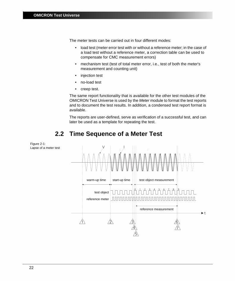
2.2 Time Sequence of a Meter TestFigure 2-1:Lapse of a meter test
t
1 2 34
5
6
7
V I
0 1 2 3 4 5 6 7 8 9
warm-up time start-up time test object measurement
reference measurement
test object
reference meter
23
Meter
1. Warm-up time:
– If the test is started with the icon, the specified warm-up time precedes the actual test.
– If the button N O M I N A L V O L T A G E O N is pressed prior to the test and the test is started later, the specified warm-up time is ignored. In this case the warm-up time is the time period between switching on the nominal voltage manually and the start of the test.
2. Start-up time: Here the values that are set in the following test line are output but pulses are not yet recorded.
3. The specified start-up time has elapsed: The start-up time is delayed until the meter under test outputs a pulse.
4. The first pulse received after the specified start-up time has elapsed is the initialization pulse that starts the actual test. However, this pulse is not counted.
The time measurement for the meter under test is started.
5. If the test is carried out with a reference meter, the time measurement for the reference meter is started with the first pulse received from the reference meter after the initialization pulse of the meter under test.
6. When the pulse specified under "Pulses | Nominal" (here pulse number 9) is received, the end of the first test line (line 1 in the test table) has been reached and the program goes to line 2. The time measurement stops when the last pulse is received. Now the time for the test object measurement is known. Independently of the mode, the next test line starts with the start-up time again (topic 2).
7. If the test is performed with a reference meter, the first pulse of the reference meter received after the stop pulse of the meter under test is the stop criterion. Until this moment, the generators remain switched on. Now the time for the reference measurement is known. Normally this time will differ slightly from the time of the test object measurement. To obtain exactly the same time base for both measurements, the energy value of the reference meter is corrected by calculating the meter error by the factor tTO / tRef.
The test continues with the next test line with no interruption of the voltage.
When the last test line is reached, the voltage remains switched on if the button "Nominal Voltage ON" was set.
Otherwise the voltage is switched off after the last test line is passed.
OMICRON Test Universe
24
2.3 Meter Example 1: Testing a Static CT/PT-Operated MeterSample files:
• Meter1-7ED62.met
• Meter1-7ED62.ohc
• Meter1-7ED62.rio
Stored at:
...OTU installation path\Test Library\Samples\SW Manual Examples\ Measurement
TaskThe electronic meter 7 ED 62 71-1A A00-8AA0 (Siemens) is to be tested.
This is a multifunctional meter with four pulse outputs (semiconductor relays). However, in this example, only the "active power import" (WV+) quantity is tested. Therefore, only one pulse output (IMPW+, terminals 20 +, 21 -) is used.
The meter is used in a three-phase four-wire system and is connected to the test set accordingly. It receives the secondary quantities from the instrument transformers. The specifications of the meter are:
• Three-phase four-wire meter for active and reactive power
• Two energy directions
• Accuracy: Class 1 for active and reactive power
• 4 pulse outputs
• VN (nominal voltage): 3 x 57.74 / 100 V
• IN (nominal current): 1 A
• Pulse rate: 10,000 pulses / kWh
• Pulse width: approx. 100 ms
The following test steps are carried out, based on the PTB standard:
• Accuracy test for a number of specified test points
• Test the creep behaviour
• Test the no-load behaviour
• Check the counting mechanism
The CMC156 EP test set with the Meter test module is available for the test.

25
Meter
2.3.1 Considerations Prior to the Test:The power resulting from the nominal values is:
P = 57.74 x 1 x 3 = 173.20W.
According to the pulse rate, one pulse corresponds to 0.1 Wh or 360 Ws. Thus, one pulse at nominal power is counted approximately every two seconds. One of the 10 binary inputs can be used for this test, because each can be used for a frequency of up to 3 kHz and a minimum pulse width of 0.15 ms.
For higher pulse rates and shorter pulse widths, two counter inputs at the rear are available ("ext. Interf.", up to 100 kHz).
2.3.2 Test SetupFigure 2-2:Connecting the meter to the CMC 156 test set
Pule outputs
OMICRON Test Universe
26
2.3.3 Starting Meter in Stand-alone ModeStart Meter in stand-alone mode from the OMICRON Start Page by clicking M E T E R .
2.3.4 Setting up the Test ObjectTo configure the relay you are testing, use the Test Object software function. Open Test Object either by using the pull-down menu item P A R A M E T E R S | T E S T O B J E C T or by clicking the Test Object icon in the toolbar. In Test Object you can browse, access and edit the test object parameters.
A detailed description of Test Object and the closely related subject "XRIO" can be found in section 3 ”Setting up the Test Object” of the "Concept" manual.
2.3.5 Configuring the HardwareSelect P A R A M E T E R S | H A R D W A R E C O N F I G U R A T I O N , and then click the Binary / Analog Inputs tab. Here, define binary input 1 (Bin. In. 1) as a pulse input for "Wh exp." to reflect the hardware setup shown in the connection diagram figure 2-2.
To do so, clear the "Binary" check box and select "Counter" instead for binary input 1. You may have to scroll horizontally all the way to the end to find the Counter check box. Then click the table cell "1" right underneath Counter, and select the test module input signal "WH exp." for binary input 1.
In this example, the binary input 1 could also be assigned to "Common" because only one pulse output is used.
27
Meter
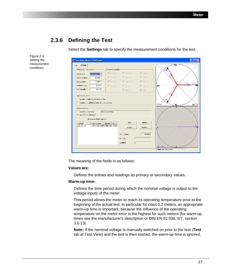
2.3.6 Defining the TestSelect the Settings tab to specify the measurement conditions for the test.
Figure 2-3:Setting the measurement conditions
The meaning of the fields is as follows:
Values are:
Defines the entries and readings as primary or secondary values.
Warm-up time:
Defines the time period during which the nominal voltage is output to the voltage inputs of the meter.
This period allows the meter to reach its operating temperature prior to the beginning of the actual test. In particular for class 0.2 meters, an appropriate warm-up time is important, because the influence of the operating temperature on the meter error is the highest for such meters (for warm-up times see the manufacturer's description or DIN EN 61 036, 5/7, section 3.6.13).
Note: If the nominal voltage is manually switched on prior to the test (Test tab at Test View) and the test is then started, the warm-up time is ignored.
OMICRON Test Universe
28
Start-up time:
Defines the time that immediately follows the warm-up time without any interruption of the voltage. During the start-up time, the quantities defined for the subsequent test line are output. The meter starts to output pulses. The first pulse after the start-up time has elapsed is the initialization pulse (number 0) for the start of the test.
Ambient Temperature and Relative Humidity:
Define the values of the ambient temperature and the relative humidity. These values later appear in the test report.
The current and voltage sources of the CMC 156 EP are used as references for the test.
Test ConfigurationThe two options at Test Configuration influence the test behaviour of no-load and creep tests.
Accept one pulse in the no-load test
Applies to no-load tests. If this option is cleared, a no-load test is a "definite no motion" test, i.e., the meter must not carry out a complete rotation. The Meter test module will assess the test as "meter started" when it detects one pulse.
If the option is selected, one pulse (which may only be a slight movement of the meter disc), is tolerated and still assessed as "meter not started".
Require one additional pulse in the Creep Test
Applies to creep tests. If this option is cleared, a creep test checks whether or not the meter disc starts moving at a specifed current, and expects the exact number of set pulses (set at "Pulses / Rotation" on the Meter Parameters tab at Test Object) within the creep test time. Generally this will be one pulse since most meters have discs that provide exactly one pulse per rotation.
If the option is selected, the creep test requires one additional pulse to consider the meter "started", for example two pulses. With the option selected, detecting only one pulse will not assess the test as "meter started".
Switch to the Test tab in order to define the test lines.
29
Meter
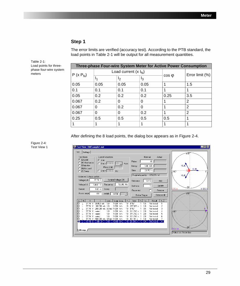
Step 1The error limits are verified (accuracy test). According to the PTB standard, the load points in Table 2-1 will be output for all measurement quantities.
Table 2-1:Load points for three-phase four-wire system meters
After defining the 8 load points, the dialog box appears as in Figure 2-4.
Figure 2-4:Test View 1
Three-phase Four-wire System Meter for Active Power Consumption
P (x PN)Load current (x IN)
cos ϕ Error limit (%)I1 I2 I3
0.05 0.05 0.05 0.05 1 1.50.1 0.1 0.1 0.1 1 10.05 0.2 0.2 0.2 0.25 3.50.067 0.2 0 0 1 20.067 0 0.2 0 1 20.067 0 0 0.2 1 20.25 0.5 0.5 0.5 0.5 11 1 1 1 1 1
OMICRON Test Universe
30
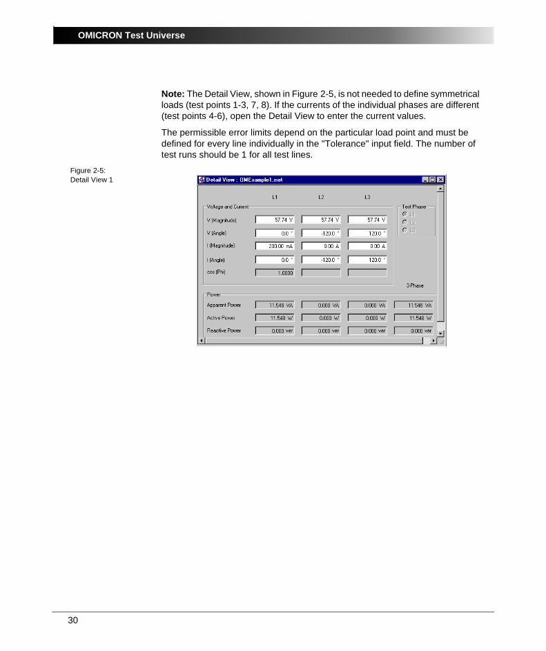
Note: The Detail View, shown in Figure 2-5, is not needed to define symmetrical loads (test points 1-3, 7, 8). If the currents of the individual phases are different (test points 4-6), open the Detail View to enter the current values.
The permissible error limits depend on the particular load point and must be defined for every line individually in the "Tolerance" input field. The number of test runs should be 1 for all test lines.
Figure 2-5:Detail View 1

31
Meter
Step 2The next step is testing the creep behaviour, i.e., testing whether the meter starts or not. The "Creep" test mode must be selected and, according to the PTB standard, a load current of 0,005 x IN = 5 mA must be output at cos ϕ = 1.
This test can be performed with either a single pulse as passed/failed criteria or the necessitiy of an additional pulse. See "Test Configuration" on page 28, "Require one additional pulse in the Creep Test", for more information.
This test line is inserted into the test table as line 9 shown below.Figure 2-6:Test View 2
The setting of the creep current is defined as a percentage of the nominal current. The default value is 1 %. Therefore the setting for a current of 5 mA is 0.5 %.
OMICRON Test Universe
32
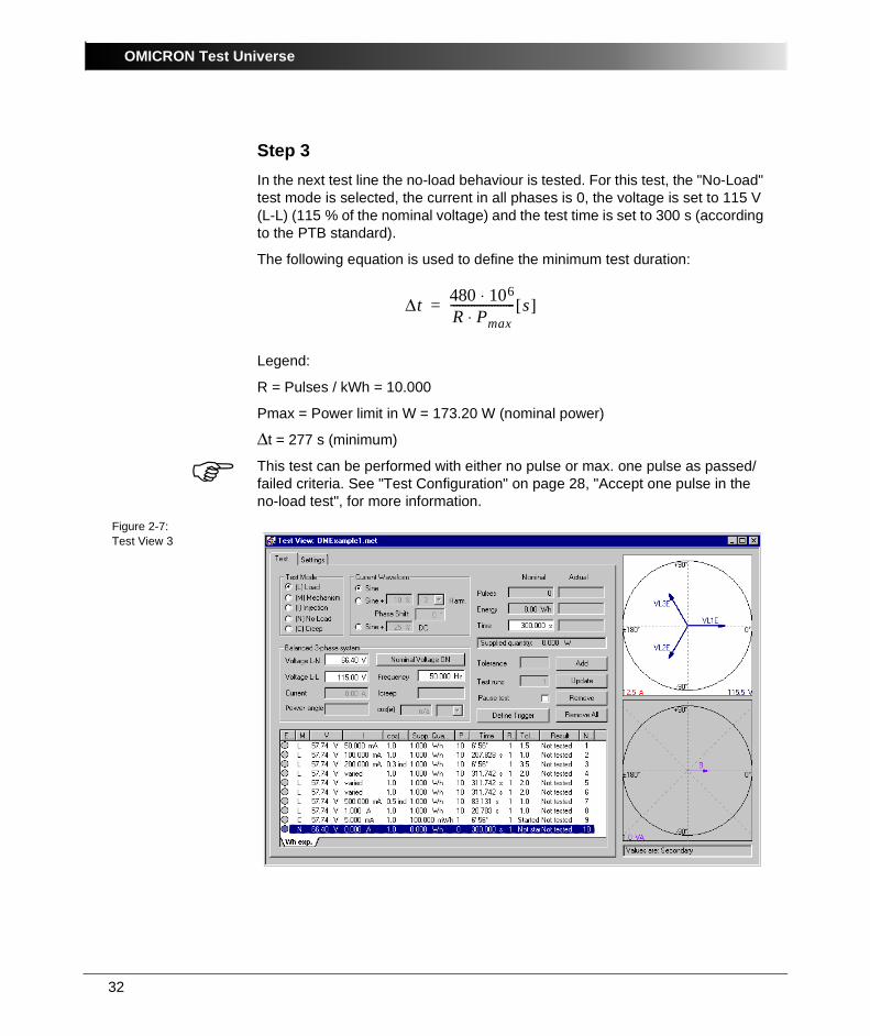
Step 3In the next test line the no-load behaviour is tested. For this test, the "No-Load" test mode is selected, the current in all phases is 0, the voltage is set to 115 V (L-L) (115 % of the nominal voltage) and the test time is set to 300 s (according to the PTB standard).
The following equation is used to define the minimum test duration:
Legend:
R = Pulses / kWh = 10.000
Pmax = Power limit in W = 173.20 W (nominal power)
Δt = 277 s (minimum)
This test can be performed with either no pulse or max. one pulse as passed/failed criteria. See "Test Configuration" on page 28, "Accept one pulse in the no-load test", for more information.
Figure 2-7:Test View 3
Δt 480 106⋅R Pmax⋅---------------------- s[ ]=
33
Meter
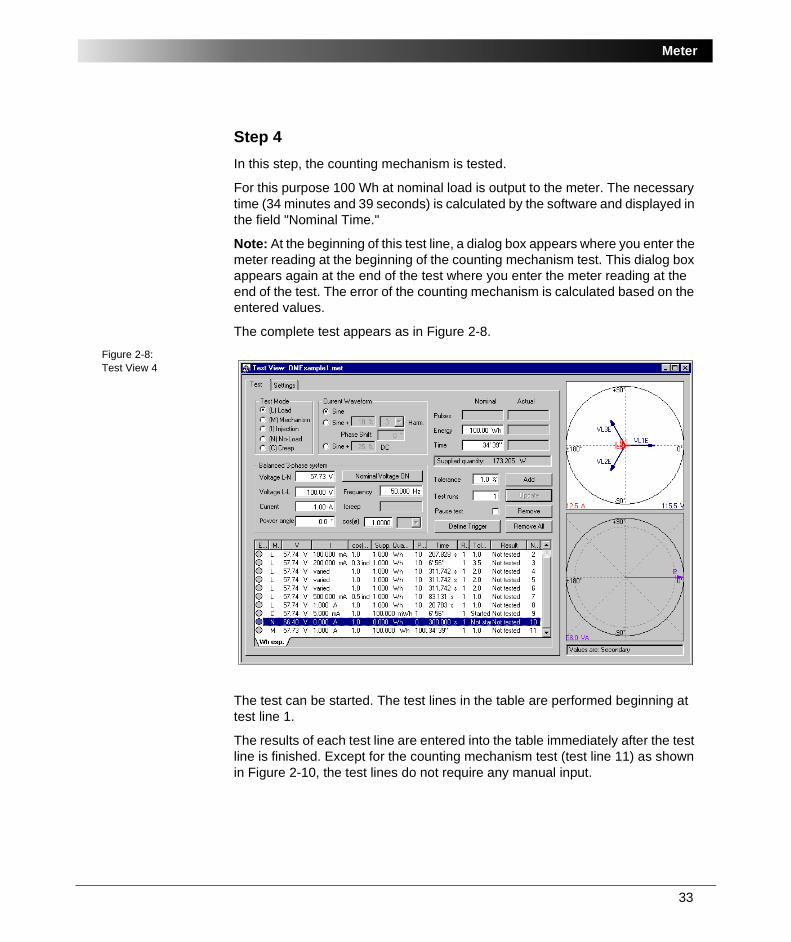
Step 4In this step, the counting mechanism is tested.
For this purpose 100 Wh at nominal load is output to the meter. The necessary time (34 minutes and 39 seconds) is calculated by the software and displayed in the field "Nominal Time."
Note: At the beginning of this test line, a dialog box appears where you enter the meter reading at the beginning of the counting mechanism test. This dialog box appears again at the end of the test where you enter the meter reading at the end of the test. The error of the counting mechanism is calculated based on the entered values.
The complete test appears as in Figure 2-8.Figure 2-8:Test View 4
The test can be started. The test lines in the table are performed beginning at test line 1.
The results of each test line are entered into the table immediately after the test line is finished. Except for the counting mechanism test (test line 11) as shown in Figure 2-10, the test lines do not require any manual input.
OMICRON Test Universe
34
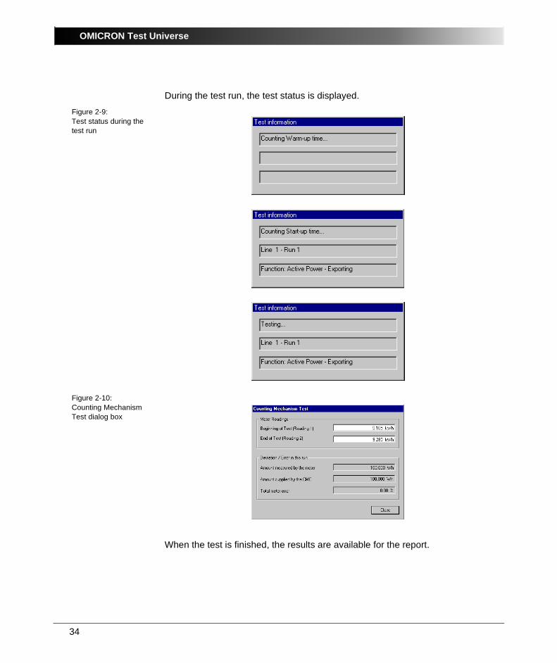
During the test run, the test status is displayed.
Figure 2-9:Test status during the test run
Figure 2-10:Counting Mechanism Test dialog box
When the test is finished, the results are available for the report.
35
Meter
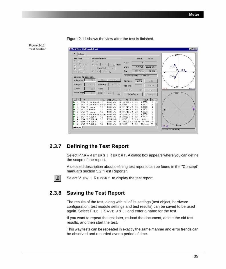
Figure 2-11 shows the view after the test is finished.
Figure 2-11:Test finished
2.3.7 Defining the Test ReportSelect P A R A M E T E R S | R E P O R T . A dialog box appears where you can define the scope of the report.
A detailed description about defining test reports can be found in the "Concept" manual’s section 5.2 ”Test Reports”.
Select V I E W | R E P O R T to display the test report.
2.3.8 Saving the Test ReportThe results of the test, along with all of its settings (test object, hardware configuration, test module settings and test results) can be saved to be used again. Select F I L E | S A V E A S . . . and enter a name for the test.
If you want to repeat the test later, re-load the document, delete the old test results, and then start the test.
This way tests can be repeated in exactly the same manner and error trends can be observed and recorded over a period of time.
OMICRON Test Universe
36
2.4 Meter Example 2: Testing an Electromechanical MeterSample files:
• Meter2-ML266.met
• Meter2-ML266.ohc
• Meter2-ML266.rio
Stored at:
...OTU installation path\Test Library\Samples\SW Manual Examples\ Measurement
TaskA three-phase meter with the ML266 (Landis & Gyr) induction measuring element is to be tested.
The meter measures "active power import" (Wh.-exp.) and has a backstop for the other energy direction. The rotations of the meter disk are read optically with a photoelectric pick-up head.
The meter is used in a three-phase four-wire system and is connected to the test set accordingly. The meter is connected directly to the voltages (3 x 220 V L-N) and via a 100/5 current instrument transformer.
The specifications of the meter are as follows:
• Three-phase four-wire meter for active power
• One energy direction
• Accuracy: class 0.5 s
• Meter disk for a pick-up of the rotations
• Vnom: 3 x 220 V / 380 V
• Inom: 5 A
• Primary pulse rate: 37.5 rotations / kWh which results in 750 pulses / kWh secondary
• Pulse width of the pick-up head: approx. 1 ms
37
Meter
The following test steps are carried out, based on the PTB standard:
• Accuracy test for a number of specified test points
• Test the creep behaviour
• Test the no-load behaviour
• Check the counting mechanism
A CMC 256 test set with the Meter software module and accessory equipment (consisting of CMLIB B, power supply for CMLIB B, photoelectric pick-up head SH2003 and connecting cables) is available for the test.
According to the test procedures of the user, a reference meter must be used. For this purpose the three-phase TVE 102/3 (Landis & Gyr) meter is available.
SolutionThe test is carried out with the following steps:
2.4.1 Considerations Prior to the TestThe power resulting from the nominal values is:
P = 220 V x 5 A x 3 = 3300 W
According to the meter constant, one rotation of the meter disk corresponds to 1.333 Wh or 4800 Ws. Thus, at nominal power, there is one rotation approximately every 1.5 seconds and one pulse is output from the pick-up head. One of the 10 binary inputs can be used to monitor this, because they can be used for frequencies of up to 3 kHz and a minimum pulse width of 0.15 ms.
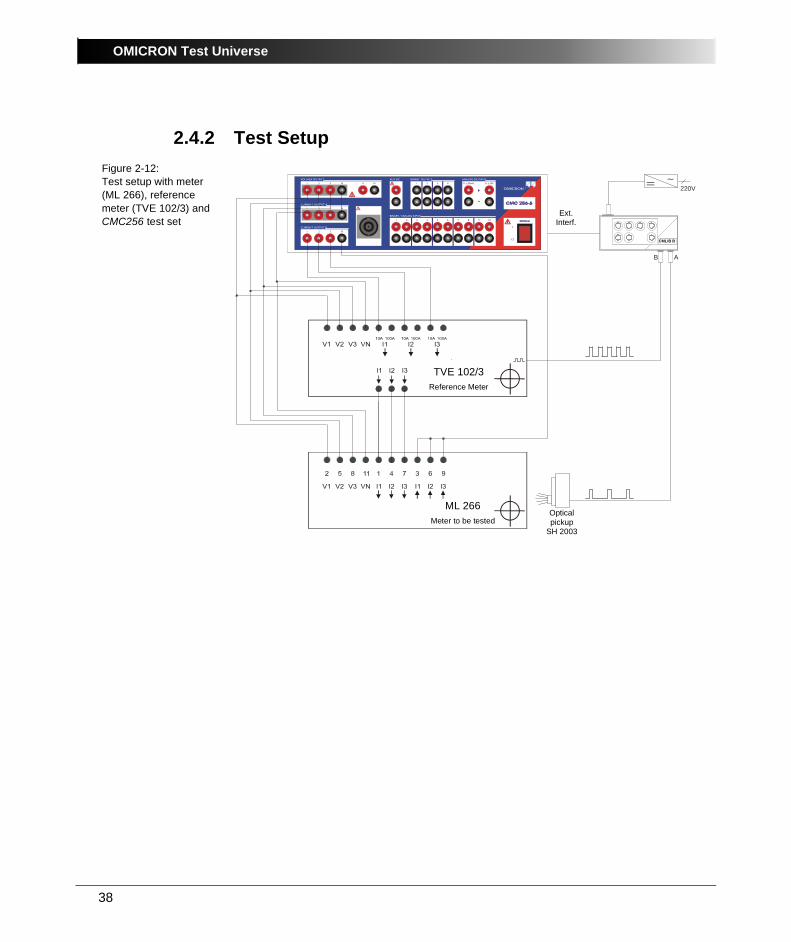
Because the pick-up head uses a connecting cable with a five-pole connector to connect to the CMLIB B, connect the pick-up head via CMLIB B (socket A) to counter input 1 (see Figure 2-12: "Test setup with meter (ML 266), reference meter (TVE 102/3) and CMC256 test set" on page 38).
The reference meter has a similar connection and is connected to counter input 2 via socket B. In this example, the reference meter must be connected via socket B of CMLIB B because the meter constant of the reference meter is 50 x 106 pulses / kWh which would exceed the capacity of the CMC 256. For the current input range of 0 ... 1 A at 220 V, this corresponds to a relatively high pulse rate of 9 kHz.
Only the RF counter input of the CMLIB B is able to read such a high pulse frequency correctly.
OMICRON Test Universe
38
2.4.2 Test SetupFigure 2-12:Test setup with meter (ML 266), reference meter (TVE 102/3) and CMC256 test set 1 2 3
1
4
2
5
3
6
4
7 8
0..±20mA
9 10
0..±10V
BINARY / ANALOG INPUT
BINARY OUTPUTAUX DC ANALOG DC INPUT
1 2 3 N
CURRENT OUTPUT B
1 2 3 4N N
VOLTAGE OUTPUT
1 2 3 N
CURRENT OUTPUT A
∼= 220V
B A
TVE 102/3Reference Meter
ML 266Meter to be tested
Ext. Interf.
Opticalpickup
SH 2003
CMLIB B
39
Meter
2.4.3 Starting Meter in Stand-alone ModeStart Meter in stand-alone mode from the OMICRON Start Page by clicking M E T E R .
2.4.4 Setting up the Test ObjectTo configure the meter you are testing, use the Test Object software function. Open Test Object either by using the pull-down menu item P A R A M E T E R S | T E S T O B J E C T or by clicking the Test Object icon in the toolbar. In Test Object you can browse, access and edit the test object parameters.
A detailed description of Test Object and the closely related subject "XRIO" can be found in section 3 ”Setting up the Test Object” of the "Concept" manual.
2.4.5 Configuring the HardwareSelect P A R A M E T E R S | H A R D W A R E C O N F I G U R A T I O N and then click the Binary / Analog Inputs tab to define counter input 1 as a pulse input for "Wh exp." of the meter being tested.
Define the counter input 2 as a pulse input for the reference meter.
OMICRON Test Universe
40
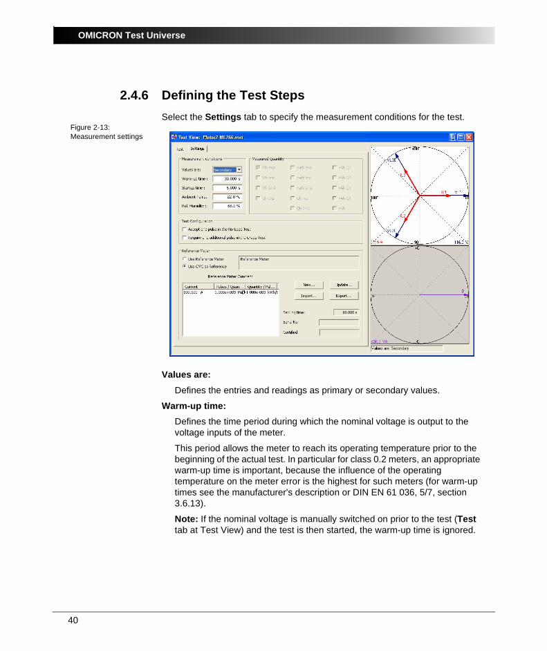
2.4.6 Defining the Test StepsSelect the Settings tab to specify the measurement conditions for the test.
Figure 2-13:Measurement settings
Values are:Defines the entries and readings as primary or secondary values.
Warm-up time:Defines the time period during which the nominal voltage is output to the voltage inputs of the meter.
This period allows the meter to reach its operating temperature prior to the beginning of the actual test. In particular for class 0.2 meters, an appropriate warm-up time is important, because the influence of the operating temperature on the meter error is the highest for such meters (for warm-up times see the manufacturer's description or DIN EN 61 036, 5/7, section 3.6.13).
Note: If the nominal voltage is manually switched on prior to the test (Test tab at Test View) and the test is then started, the warm-up time is ignored.

41
Meter
Start-up time:Defines the time that immediately follows the warm-up time without any interruption of the voltage. During the start-up time, the quantities defined for the subsequent test line are output. The meter starts to output pulses. The first pulse after the start-up time has elapsed is the initialization pulse (number 0) for the start of the test.
Ambient Temperature and Relative Humidity:
Define the values of the ambient temperature and the relative humidity. These values later appear in the test report.
The TVE 102/103 meter is used as the reference for the test. Select "Use Reference Meter" and click the N E W button to define the reference meter.
Figure 2-14:Defining a new reference meter
In this example, the reference meter has three different meter constants based on the current input range.
When you have finished defining the reference meter, click O K to return to the Settings tab.
Note: To make the settings of this reference meter available for other tests, save them to a text file (*.rmf). You can do this with the E X P O R T button in the Settings tab.
The settings of several meters can be saved together in one .rmf file. The data of the reference meter you have just defined are shown in Figure 2-15.
OMICRON Test Universe
42
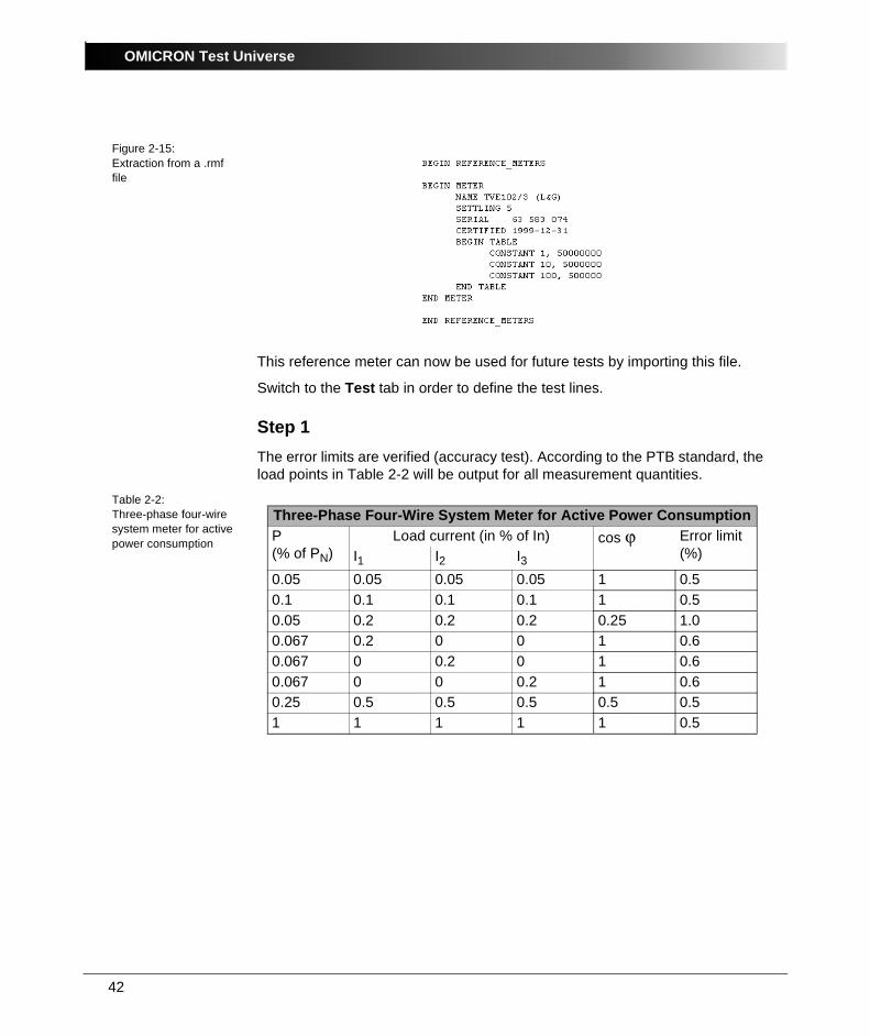
Figure 2-15:Extraction from a .rmf file
This reference meter can now be used for future tests by importing this file.
Switch to the Test tab in order to define the test lines.
Step 1The error limits are verified (accuracy test). According to the PTB standard, the load points in Table 2-2 will be output for all measurement quantities.
Table 2-2:Three-phase four-wire system meter for active power consumption
Three-Phase Four-Wire System Meter for Active Power ConsumptionP(% of PN)
Load current (in % of In) cos ϕ Error limit (%)I1 I2 I3
0.05 0.05 0.05 0.05 1 0.50.1 0.1 0.1 0.1 1 0.50.05 0.2 0.2 0.2 0.25 1.00.067 0.2 0 0 1 0.60.067 0 0.2 0 1 0.60.067 0 0 0.2 1 0.60.25 0.5 0.5 0.5 0.5 0.51 1 1 1 1 0.5
43
Meter
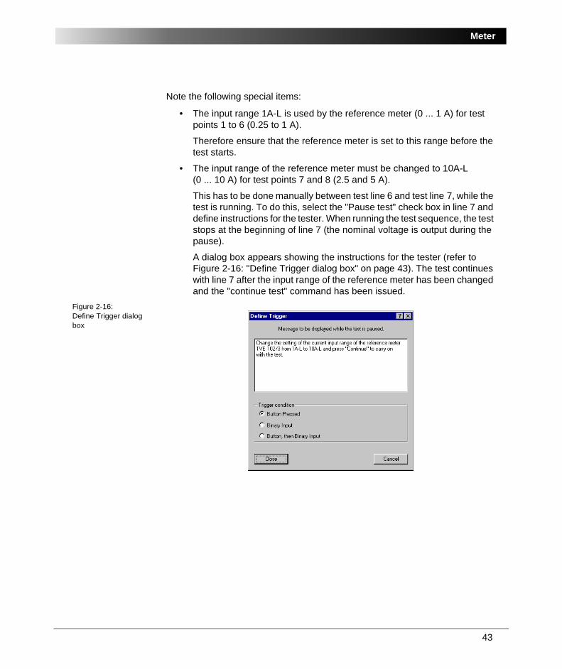
Note the following special items:
• The input range 1A-L is used by the reference meter (0 ... 1 A) for test points 1 to 6 (0.25 to 1 A).
Therefore ensure that the reference meter is set to this range before the test starts.
• The input range of the reference meter must be changed to 10A-L (0 ... 10 A) for test points 7 and 8 (2.5 and 5 A).
This has to be done manually between test line 6 and test line 7, while the test is running. To do this, select the "Pause test" check box in line 7 and define instructions for the tester. When running the test sequence, the test stops at the beginning of line 7 (the nominal voltage is output during the pause).
A dialog box appears showing the instructions for the tester (refer to Figure 2-16: "Define Trigger dialog box" on page 43). The test continues with line 7 after the input range of the reference meter has been changed and the "continue test" command has been issued.
Figure 2-16:Define Trigger dialog box
OMICRON Test Universe
44
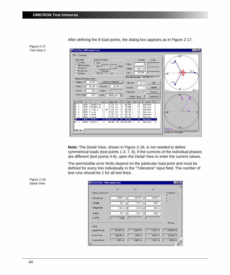
After defining the 8 load points, the dialog box appears as in Figure 2-17.
Figure 2-17:Test View 1
Note: The Detail View, shown in Figure 2-18, is not needed to define symmetrical loads (test points 1-3, 7, 8). If the currents of the individual phases are different (test points 4-6), open the Detail View to enter the current values.
The permissible error limits depend on the particular load point and must be defined for every line individually in the "Tolerance" input field. The number of test runs should be 1 for all test lines.
Figure 2-18:Detail View
45
Meter
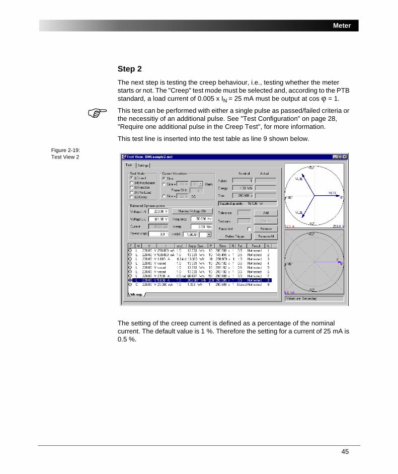
Step 2The next step is testing the creep behaviour, i.e., testing whether the meter starts or not. The "Creep" test mode must be selected and, according to the PTB standard, a load current of 0.005 x IN = 25 mA must be output at cos ϕ = 1.
This test can be performed with either a single pulse as passed/failed criteria or the necessitiy of an additional pulse. See "Test Configuration" on page 28, "Require one additional pulse in the Creep Test", for more information.
This test line is inserted into the test table as line 9 shown below.Figure 2-19:Test View 2
The setting of the creep current is defined as a percentage of the nominal current. The default value is 1 %. Therefore the setting for a current of 25 mA is 0.5 %.
OMICRON Test Universe
46
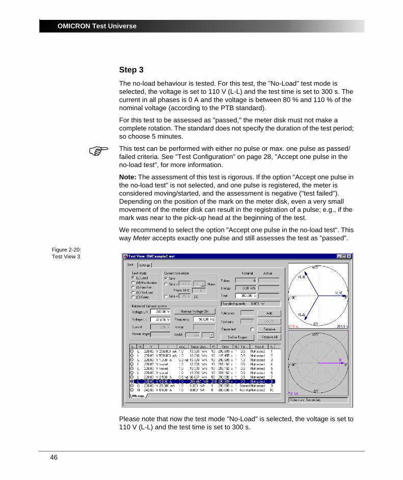
Step 3The no-load behaviour is tested. For this test, the "No-Load" test mode is selected, the voltage is set to 110 V (L-L) and the test time is set to 300 s. The current in all phases is 0 A and the voltage is between 80 % and 110 % of the nominal voltage (according to the PTB standard).
For this test to be assessed as "passed," the meter disk must not make a complete rotation. The standard does not specify the duration of the test period; so choose 5 minutes.
This test can be performed with either no pulse or max. one pulse as passed/failed criteria. See "Test Configuration" on page 28, "Accept one pulse in the no-load test", for more information.
Note: The assessment of this test is rigorous. If the option "Accept one pulse in the no-load test" is not selected, and one pulse is registered, the meter is considered moving/started, and the assessment is negative ("test failed"). Depending on the position of the mark on the meter disk, even a very small movement of the meter disk can result in the registration of a pulse; e.g., if the mark was near to the pick-up head at the beginning of the test.
We recommend to select the option "Accept one pulse in the no-load test". This way Meter accepts exactly one pulse and still assesses the test as "passed".
Figure 2-20:Test View 3
Please note that now the test mode "No-Load" is selected, the voltage is set to 110 V (L-L) and the test time is set to 300 s.
47
Meter
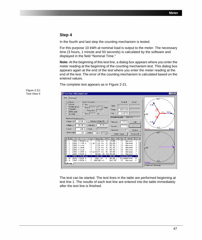
Step 4In the fourth and last step the counting mechanism is tested.
For this purpose 10 kWh at nominal load is output to the meter. The necessary time (3 hours, 1 minute and 50 seconds) is calculated by the software and displayed in the field "Nominal Time."
Note: At the beginning of this test line, a dialog box appears where you enter the meter reading at the beginning of the counting mechanism test. This dialog box appears again at the end of the test where you enter the meter reading at the end of the test. The error of the counting mechanism is calculated based on the entered values.
The complete test appears as in Figure 2-21.Figure 2-21:Test View 4
The test can be started. The test lines in the table are performed beginning at test line 1. The results of each test line are entered into the table immediately after the test line is finished.
OMICRON Test Universe
48
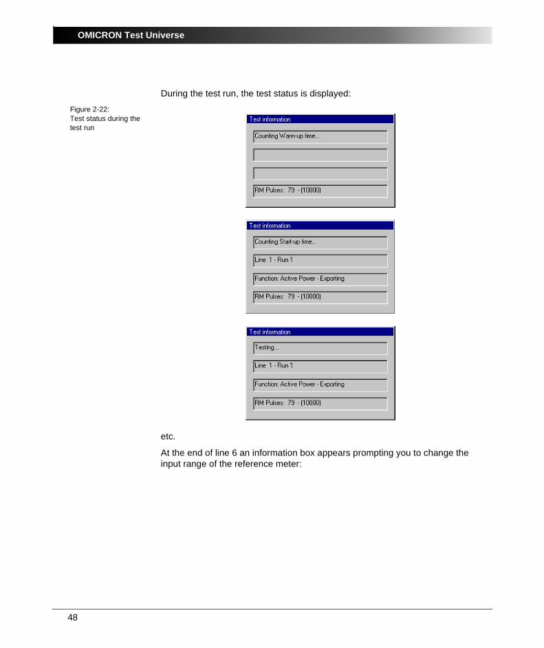
During the test run, the test status is displayed:
Figure 2-22:Test status during the test run
etc.
At the end of line 6 an information box appears prompting you to change the input range of the reference meter:
49
Meter
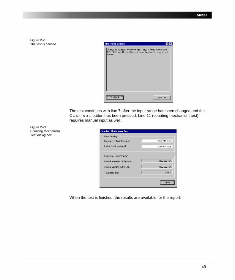
Figure 2-23:The test is paused
The test continues with line 7 after the input range has been changed and the C O N T I N U E button has been pressed. Line 11 (counting mechanism test) requires manual input as well.
Figure 2-24:Counting Mechanism Test dialog box
When the test is finished, the results are available for the report.
OMICRON Test Universe
50
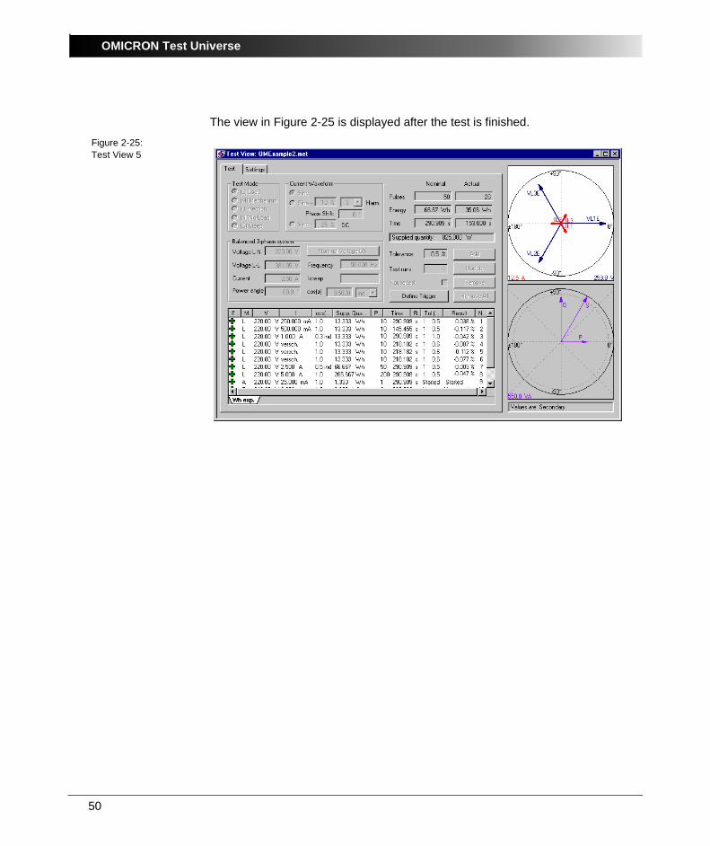
The view in Figure 2-25 is displayed after the test is finished.
Figure 2-25:Test View 5

51
Meter
2.4.7 Defining the Test ReportSelect P A R A M E T E R S | R E P O R T | R E P O R T S E T T I N G S and click D E F I N E . A dialog box appears where you can define the scope of the report.
Choose the "Condensed Report."
Figure 2-26:Defining the test report
The condensed test report appears as in Figure 2-27.
Figure 2-27:Condensed test report (extract)
The report can either be printed or exported to a file in RTF format (Rich Text Format). The file is later available for further processing with other programs (e.g., Word for Windows).
OMICRON Test Universe
52
2.4.8 Saving the Test ReportThe results of the test, along with all of its settings (test object, hardware configuration, test module settings and test results) can be saved to be used again.
Select F I L E | S A V E A S . . . and enter a name for the test.
If you want to repeat the test later, re-load the document, delete the old test results, and then start the test.
This way tests can be repeated in exactly the same manner and error trends can be observed and recorded over a period of time.

53
Meter
2.5 Meter Example 3: Testing a Multifunctional Electronical MeterSample files:
• Meter3-7ED62Multifunctional.met
• Meter3-7ED62Multifunctional.ohc
• Meter3-7ED62Multifunctional.rio
...OTU installation path\Test Library\Samples\SW Manual Examples\ Measurement
TaskThe electronic transformer-operated electricity meter 7 ED 62 24-4E E82-8BC1 (Siemens) is to be tested.
The test meter is is a multifunctional meter with 4 pulse outputs (semiconductor relays) that is parameterized as follows:
• "active power import" (WV+), output IMPW+, terminals 20 +, 21 -
• "reactive power import" (BV+), output IMPB+, terminals 22 +, 21 -
• "active power export" (WV-), output IMPW-, terminals 23 +, 21 -
• "reactive power export" (BV-), output IMPB-, terminals 24 +, 21 -
The meter is used in a three-phase four-wire system and is connected to the test set accordingly. It is connected directly to the voltages (3 x 230 V L-N) and via a current instrument transformer (In = 5 A).
The specifications of the meter are as follows:
• Three-phase four-wire meter for active and reactive power
• Two energy directions
• Accuracy: class 0.2 s for active and reactive power
• 4 pulse outputs
• Vnom: 3 x 230 V / 400 V
• Inom: 5 A
• Pulse rate: 2000 pulses / kWh
• Pulse width: approx. 100 ms
OMICRON Test Universe
54
The following test steps are carried out, based on the PTB standard:
• Accuracy test for a number of specified test points
• Test the creep behaviour
• Test the no-load behaviour
• Check the counting mechanism
The CMC 156 EP test set with the CMS 156 voltage amplifier and the Meter software module are available for the test.
Solution:
The test is carried out with the following steps:
2.5.1 Considerations Prior to the TestThe power resulting from the nominal values is:
P = 230V x 5A x 3 = 3.450 W
According to the pulse rate, one pulse corresponds to 0.5 Wh (0.5 varh) or 1800 Ws (vars). Thus, one pulse at nominal power is counted approximately every two seconds. For such purposes, 4 of the 10 binary inputs can be used (they can be used for a frequency of up to 3 kHz and a minimum pulse width of 0.15 ms).
55
Meter
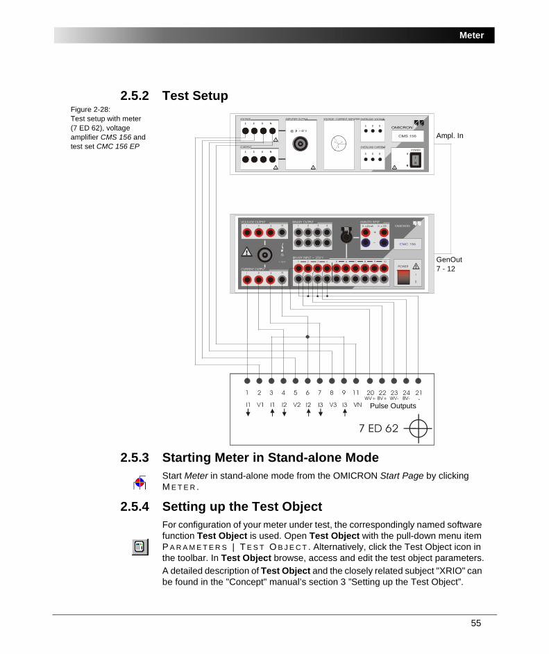
2.5.2 Test SetupFigure 2-28:Test setup with meter (7 ED 62), voltage amplifier CMS 156 and test set CMC 156 EP
2.5.3 Starting Meter in Stand-alone ModeStart Meter in stand-alone mode from the OMICRON Start Page by clicking M E T E R .
2.5.4 Setting up the Test ObjectFor configuration of your meter under test, the correspondingly named software function Test Object is used. Open Test Object with the pull-down menu item P A R A M E T E R S | T E S T O B J E C T . Alternatively, click the Test Object icon in the toolbar. In Test Object browse, access and edit the test object parameters.A detailed description of Test Object and the closely related subject "XRIO" can be found in the "Concept" manual’s section 3 ”Setting up the Test Object”.
+
_
I
0
VOLTAGE
CURRENT
1 2 3 N
1 2 3 N
AMPLIFIER OUTPUT VOLTAGE / CURRENT AMPLIFIER OVERLOAD VOLTAGE
OVERLOAD CURRENT
1 2 3
POWER1 2 3
> 42 V
Pulse Outputs
Ampl. In
GenOut 7 - 12
OMICRON Test Universe
56
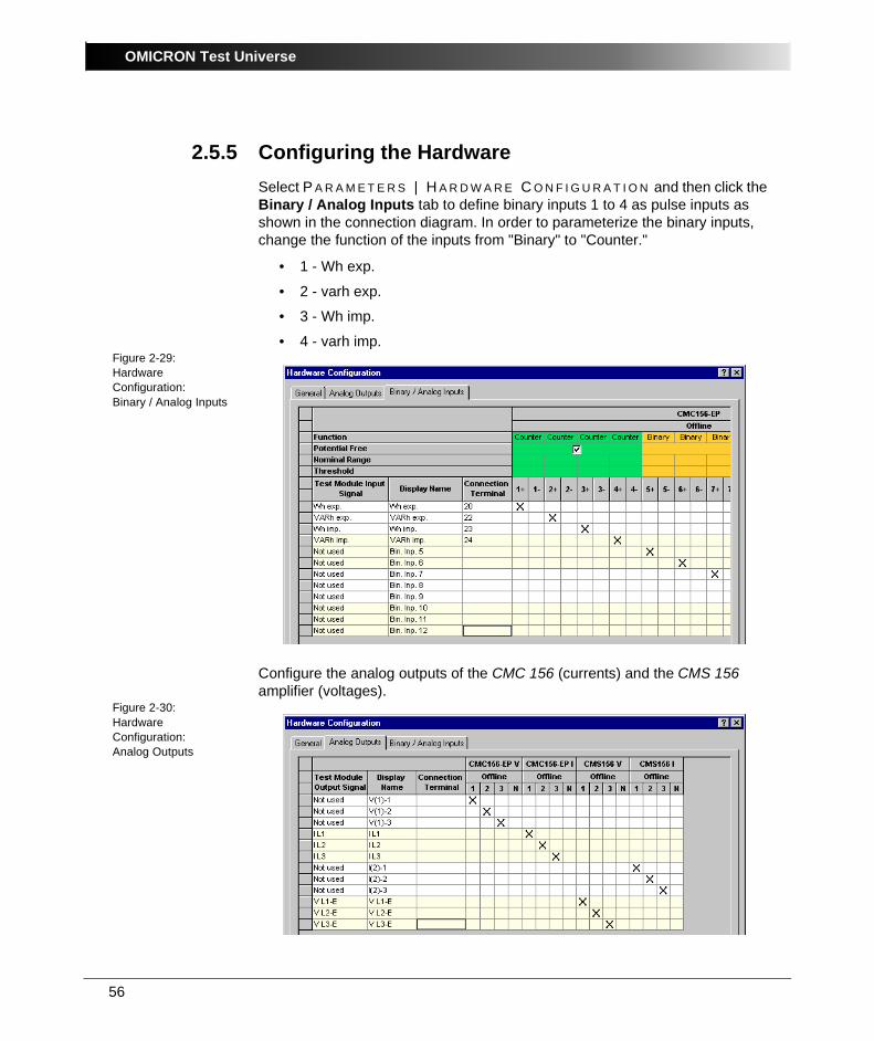
2.5.5 Configuring the HardwareSelect P A R A M E T E R S | H A R D W A R E C O N F I G U R A T I O N and then click the Binary / Analog Inputs tab to define binary inputs 1 to 4 as pulse inputs as shown in the connection diagram. In order to parameterize the binary inputs, change the function of the inputs from "Binary" to "Counter."
• 1 - Wh exp.
• 2 - varh exp.
• 3 - Wh imp.
• 4 - varh imp.Figure 2-29:Hardware Configuration:Binary / Analog Inputs
Configure the analog outputs of the CMC 156 (currents) and the CMS 156 amplifier (voltages).
Figure 2-30:Hardware Configuration: Analog Outputs
57
Meter
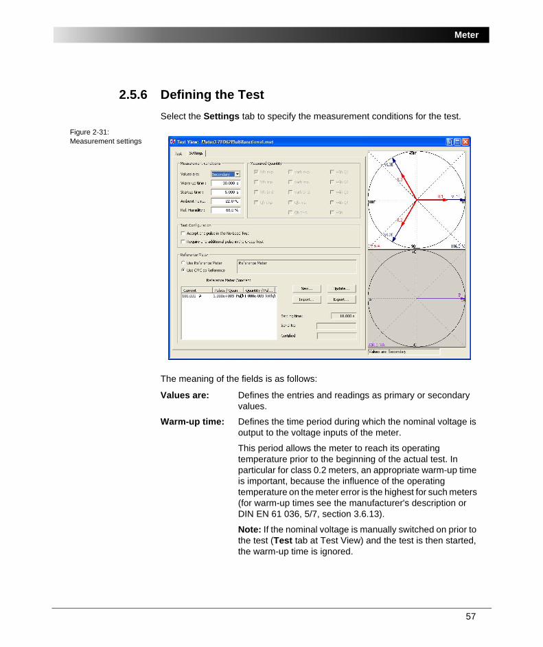
2.5.6 Defining the TestSelect the Settings tab to specify the measurement conditions for the test.
Figure 2-31:Measurement settings
The meaning of the fields is as follows:
Values are: Defines the entries and readings as primary or secondary values.
Warm-up time: Defines the time period during which the nominal voltage is output to the voltage inputs of the meter.
This period allows the meter to reach its operating temperature prior to the beginning of the actual test. In particular for class 0.2 meters, an appropriate warm-up time is important, because the influence of the operating temperature on the meter error is the highest for such meters (for warm-up times see the manufacturer's description or DIN EN 61 036, 5/7, section 3.6.13).
Note: If the nominal voltage is manually switched on prior to the test (Test tab at Test View) and the test is then started, the warm-up time is ignored.
OMICRON Test Universe
58
Start-up time: Defines the time that immediately follows the warm-up time without any interruption of the voltage. During the start-up time, the quantities defined for the subsequent test line are output. The meter starts to output pulses. The first pulse after the start-up time has elapsed is the initialization pulse (number 0) for the start of the test.
Ambient Temperature and Relative Humidity:
Define the values of the ambient temperature and the relative humidity. These values later appear in the test report.
Measured Quantity:When the "Multifunctional" meter type is selected in the test object parameters, the "Measured Quantity" group box is activated and is used to select the various measurement functions.
The current and voltage sources of the CMC 156 EP and the CMS 156 are used as references for the test.
Switch to the Test tab in order to define the test lines.
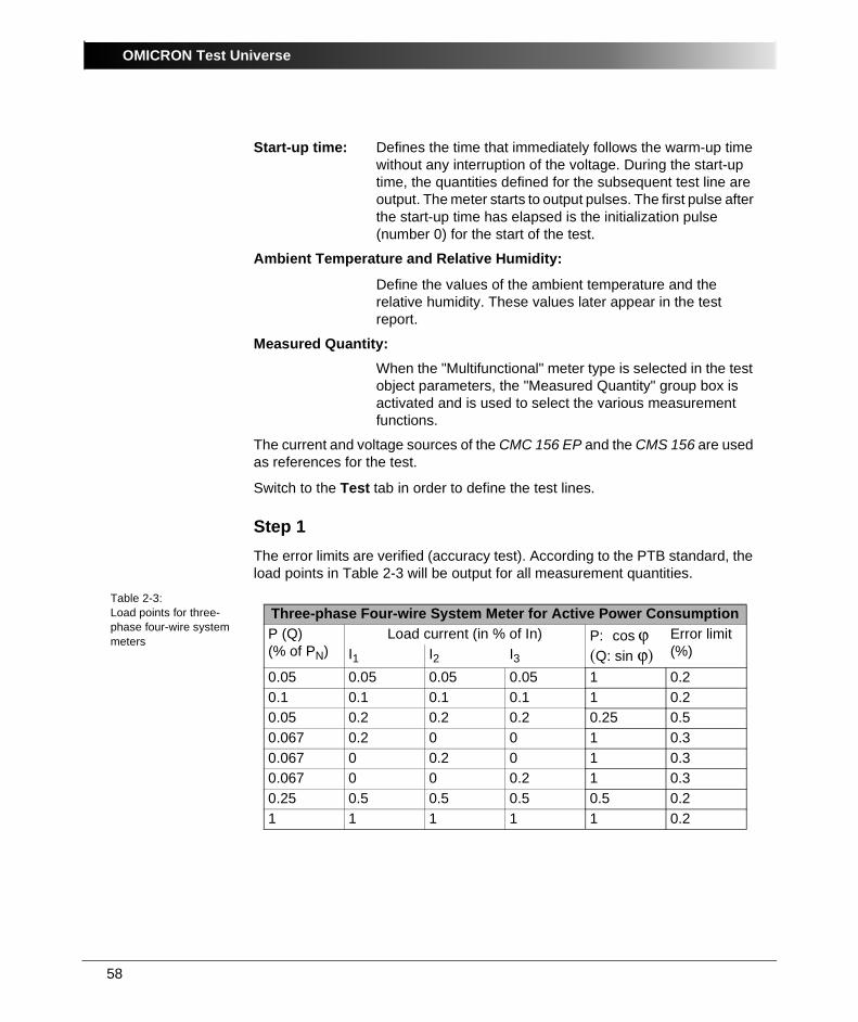
Step 1The error limits are verified (accuracy test). According to the PTB standard, the load points in Table 2-3 will be output for all measurement quantities.
Table 2-3:Load points for three-phase four-wire system meters
Three-phase Four-wire System Meter for Active Power ConsumptionP (Q) (% of PN)
Load current (in % of In) P: cos ϕ (Q: sin ϕ)
Error limit (%)I1 I2 I3
0.05 0.05 0.05 0.05 1 0.20.1 0.1 0.1 0.1 1 0.20.05 0.2 0.2 0.2 0.25 0.50.067 0.2 0 0 1 0.30.067 0 0.2 0 1 0.30.067 0 0 0.2 1 0.30.25 0.5 0.5 0.5 0.5 0.21 1 1 1 1 0.2

59
Meter
After defining the 8 load points for "Wh-exp.":Figure 2-32:Test View 1
Note: The Detail View, shown in Figure 2-33, is not needed to define symmetrical loads (test points 1-3, 7, 8). If the currents of the individual phases are different (test points 4-6), open the Detail View to enter the current values.
The permissible error limits depend on the particular load point and must be defined for every line individually in the "Tolerance" input field. The number of test runs should be 1 for all test lines.
Figure 2-33:Detail View
OMICRON Test Universe
60
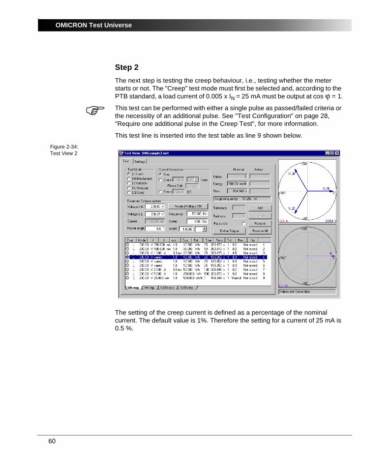
Step 2The next step is testing the creep behaviour, i.e., testing whether the meter starts or not. The "Creep" test mode must first be selected and, according to the PTB standard, a load current of 0.005 x IN = 25 mA must be output at cos ϕ = 1.
This test can be performed with either a single pulse as passed/failed criteria or the necessitiy of an additional pulse. See "Test Configuration" on page 28, "Require one additional pulse in the Creep Test", for more information.
This test line is inserted into the test table as line 9 shown below.Figure 2-34:Test View 2
The setting of the creep current is defined as a percentage of the nominal current. The default value is 1%. Therefore the setting for a current of 25 mA is 0.5 %.
61
Meter
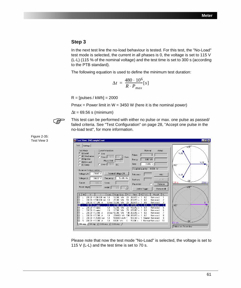
Step 3In the next test line the no-load behaviour is tested. For this test, the "No-Load" test mode is selected, the current in all phases is 0, the voltage is set to 115 V (L-L) (115 % of the nominal voltage) and the test time is set to 300 s (according to the PTB standard).
The following equation is used to define the minimum test duration:
R = [pulses / kWh] = 2000
Pmax = Power limit in W = 3450 W (here it is the nominal power)
Δt = 69.56 s (minimum)
This test can be performed with either no pulse or max. one pulse as passed/failed criteria. See "Test Configuration" on page 28, "Accept one pulse in the no-load test", for more information.
Figure 2-35:Test View 3
Please note that now the test mode "No-Load" is selected, the voltage is set to 115 V (L-L) and the test time is set to 70 s.
Δt 480 106⋅R Pmax⋅---------------------- s[ ]=
OMICRON Test Universe
62
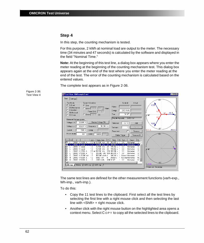
Step 4In this step, the counting mechanism is tested.
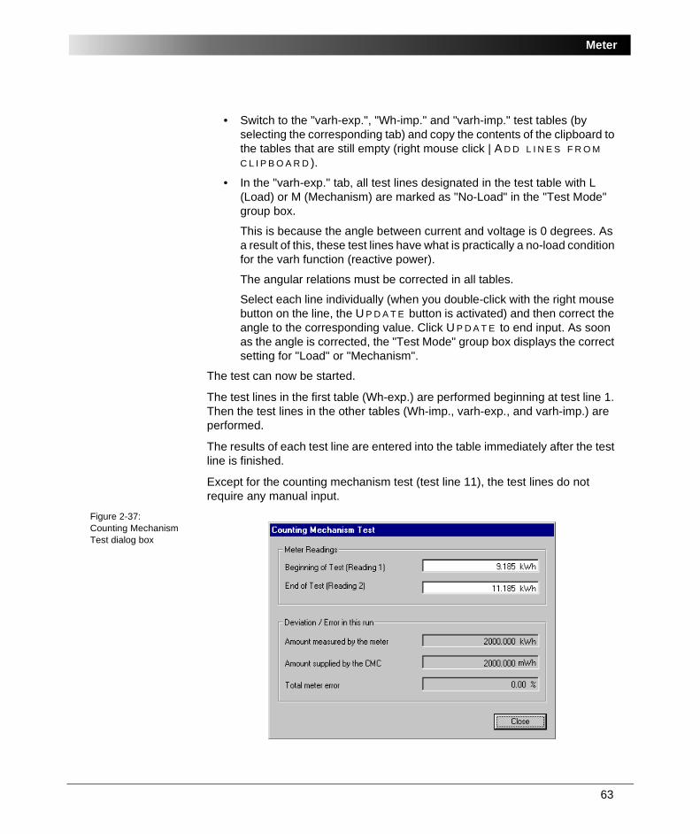
For this purpose, 2 kWh at nominal load are output to the meter. The necessary time (34 minutes and 47 seconds) is calculated by the software and displayed in the field "Nominal Time."
Note: At the beginning of this test line, a dialog box appears where you enter the meter reading at the beginning of the counting mechanism test. This dialog box appears again at the end of the test where you enter the meter reading at the end of the test. The error of the counting mechanism is calculated based on the entered values.
The complete test appears as in Figure 2-36.Figure 2-36:Test View 4
The same test lines are defined for the other measurement functions (varh-exp., Wh-imp., varh-imp.).
To do this:
• Copy the 11 test lines to the clipboard. First select all the test lines by selecting the first line with a right mouse click and then selecting the last line with <Shift> + right mouse click.
• Another click with the right mouse button on the highlighted area opens a context menu. Select C O P Y to copy all the selected lines to the clipboard.
63
Meter
• Switch to the "varh-exp.", "Wh-imp." and "varh-imp." test tables (by selecting the corresponding tab) and copy the contents of the clipboard to the tables that are still empty (right mouse click | A D D L I N E S F R O M C L I P B O A R D ).
• In the "varh-exp." tab, all test lines designated in the test table with L (Load) or M (Mechanism) are marked as "No-Load" in the "Test Mode" group box.
This is because the angle between current and voltage is 0 degrees. As a result of this, these test lines have what is practically a no-load condition for the varh function (reactive power).
The angular relations must be corrected in all tables.
Select each line individually (when you double-click with the right mouse button on the line, the U P D A T E button is activated) and then correct the angle to the corresponding value. Click U P D A T E to end input. As soon as the angle is corrected, the "Test Mode" group box displays the correct setting for "Load" or "Mechanism".
The test can now be started.
The test lines in the first table (Wh-exp.) are performed beginning at test line 1. Then the test lines in the other tables (Wh-imp., varh-exp., and varh-imp.) are performed.
The results of each test line are entered into the table immediately after the test line is finished.
Except for the counting mechanism test (test line 11), the test lines do not require any manual input.
Figure 2-37:Counting Mechanism Test dialog box
OMICRON Test Universe
64
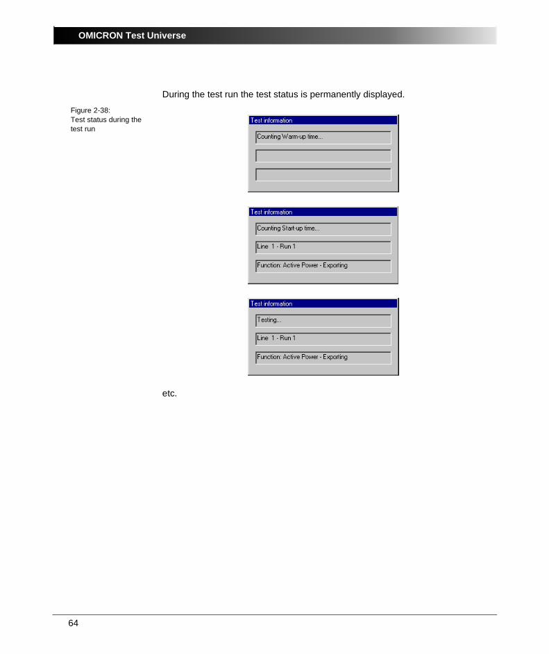
During the test run the test status is permanently displayed.
Figure 2-38:Test status during the test run
etc.
65
Meter
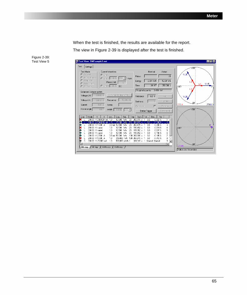
When the test is finished, the results are available for the report.
The view in Figure 2-39 is displayed after the test is finished.
Figure 2-39:Test View 5
OMICRON Test Universe
66
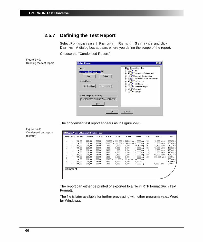
2.5.7 Defining the Test ReportSelect P A R A M E T E R S | R E P O R T | R E P O R T S E T T I N G S and click D E F I N E . A dialog box appears where you define the scope of the report.
Choose the "Condensed Report."
Figure 2-40:Defining the test report
The condensed test report appears as in Figure 2-41.
Figure 2-41:Condensed test report (extract)
The report can either be printed or exported to a file in RTF format (Rich Text Format).
The file is later available for further processing with other programs (e.g., Word for Windows).
67
Meter
2.5.8 Saving the Test ReportThe results of the test, along with all of its settings (test object, hardware configuration, test module settings and test results) can be saved to be used again.
Select F I L E | S A V E A S . . . and enter a name for the test.
If you want to repeat the test later, re-load the document, delete the old test results, and then start the test.
This way tests can be repeated in exactly the same manner and error trends can be observed and recorded over a period of time.

OMICRON Test Universe
68
69
Transducer
3 Transducer
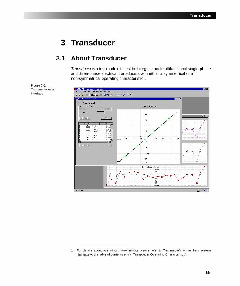
3.1 About TransducerTransducer is a test module to test both regular and multifunctional single-phase and three-phase electrical transducers with either a symmetrical or a non-symmetrical operating characteristic1.
Figure 3-1:Transducer user interface
1. For details about operating characteristics please refer to Transducer’s online help system.Navigate to the table of contents entry "Transducer Operating Characteristic".
OMICRON Test Universe
70
Single-phase electrical transducers that can be tested:• AC voltage (L-N, L-L)
• AC current
• Frequency
• Active power (W)
• Reactive power (var)
• Apparent power (VA)
• DC voltage
• DC current
• DC power
• Phase [V-V], [V-I], [I-I] in degrees
Three-phase electrical transducers that can be tested• Active power (W)
• Reactive power (var)
• Apparent power (VA)
• AC voltage (L-L)
• Power factor (Phi)
• Load Factor (of GMC, Switzerland) (1-P/S) x sgnQ
For these tests, Transducer supports the following OMICRON CMC test sets:
• CMC 56 (serial number > DAxxx)
• CMC 156
• CMC 151
• CMC 256
• CMC 256plus
Additionally, any external voltage or current amplifiers can be used.

71
Transducer
3.2 Transducers and Multifunctional Transducers.Transducers are used for precision electrical measurement and control. They are used across industry sectors such as electrical utilities, switchgear / switchboard manufacturers, energy management, building management and control, process control, and instrumentation. They provide local and remote indication in conjunction with instruments, recorders, and data loggers.
Moreover, transducers with high accuracy and reliability are becoming increasingly important features in the provision of cost effective system control.
Figure 3-2:Scheme about a typical transducer application
Transducers are designed to monitor currents, voltages, power, phase angles, or frequencies.
Multifunctional transducersDepending on the manufacturer, some programmable multifunctional transducers are capable of acquiring multiple input quantities simultaneously. A transducer converts these inputs into a proportional analog signal. These transducer outputs are then used as local and/or remote indications.
Figure 3-3:Scheme about a multifunctional transducer
Additionally, some types of multifunctional transducers provide a binary output that reacts when a threshold is exceeded. In other cases, the binary signal can be used as a counter, because it emits pulses based on the energy.
OMICRON Test Universe
72
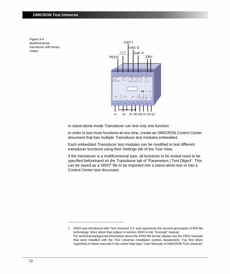
Figure 3-4:Multifunctional transducer with binary output
In stand-alone mode Transducer can test only one function.
In order to test more functions at one time, create an OMICRON Control Center document that has multiple Transducer test modules embedded.
Each embedded Transducer test modules can be modified to test different transducer functions using their Settings tab of the Test View.
If the transducer is a multifunctional type, all functions to be tested need to be specified beforehand on the Transducer tab of "Parameters | Test Object". This can be saved as a XRIO1 file to be imported into a stand-alone test or into a Control Center test document.
1. XRIO was introduced with Test Universe 2.0, and represents the second generation of RIO filetechnology. More about that subject in section XRIO in the "Concept" manual.For technical background information about the XRIO file format, please see the XRIO manualsthat were installed with the Test Universe installation (unless deselected). You find directhyperlinks to these manuals in the online help topic "User Manuals of OMICRON Test Universe"
73
Transducer
3.3 Transducer example: Active Power Transducer
Calibrating the load dependencySample file: Active Power Transducer.trd
Stored at:
...OTU installation path\Test Library\Samples\SW Manual Examples\ Measurement
TaskA Measuretronic active power transducer is to be tested.
The automatic test should verify the calibration of the transducer at a minimum of 20 test points for a variety of importing and exporting load conditions with unity power factor. In particular the full-scale error graph in dependency of load should be established.
The following settings are given for the transducer:
• General Settings:
- Inom: 1 A
- Vnom: 110 V (L-L)
- fnom: 50 Hz
- Input range: -200W .. 0W .. +200W
- Output range: -5mA .. 0mA .. +5mA
- Class: 0.5
- Type: 3 element / 4 wire
SolutionThe OMICRON Test Universe offers a dedicated test module Transducer, which is recommended to be used to test this transducer.
Individual calibration test points can be defined. An automatic test, where all test points are sequentially tested, can be run. For multi-function transducers, the various output functions of the transducer can be calibrated, by embedding multiple tests into an OMICRON Control Center document.
To simplify this example, however, the Transducer module is used stand-alone.
OMICRON Test Universe
74
3.3.1 Connecting a Transducer to the CMC Test SetPlease ensure that the correct operating procedures and test instructions for your company with respect to testing of measurement devices are followed and adhered to.
For this example the transducer is assumed to be tested stand-alone, i.e. it is not connected to the electrical system in any way. It is also assumed, that a CMC 156 is used to inject the voltages and currents to the device.
1. Connect the voltage inputs of the transducer to the corresponding voltage outputs of the CMC test set.
If a two element transducer is calibrated, the neutral voltage output (VN) of the CMC is not connected to the transducer.
2. Connect all three current inputs of the transducer to the corresponding current outputs of the CMC test set. Ensure that the current “outputs” of the transducer, i.e. the output side of the current transformers, are connected together in a starpoint, which is connected to the neutral current output (IN) of the CMC test set.
If a two element transducer is calibrated, only the current inputs for phase A and phase C need to be connected to the current outputs of the CMC. Current output 2 of the CMC (normally for phase B) must be shorted to the neutral point.
3. Connect the analog output signal of the transducer to the DC analog input (current or voltage) of the CMC.

75
Transducer
3.3.2 Starting TransducerStart Transducer in stand-alone mode from the OMICRON Start Page by clicking T R A N S D U C E R .
3.3.3 Setting up the Test ObjectFor configuration of your transducer under test, the correspondingly named software function Test Object is used. Open Test Object with the pull-down menu item P A R A M E T E R S | T E S T O B J E C T . Alternatively, click the Test Object icon in the toolbar. In Test Object browse, access and edit the test object parameters.
A detailed description of Test Object and the closely related subject "XRIO" can be found in the "Concept" manual’s section 4 ”Setting up the Test Object”.
3.3.4 Configuring the HardwareSelect P A R A M E T E R S | H A R D W A R E C O N F I G U R A T I O N to open the Hardware Configuration and to specify any hardware-related configuration of the CMC.
The configuration of the CMC amplifiers and any external OMICRON amplifiers can be specified by clicking on D E T A I L S .
Which outputs are used and how they are connected, e.g. in a three phase configuration, or connected in either parallel or series to boost the output range, can be set here.
Special signal names and connection configurations for the analog outputs and DC analog inputs can be specified on the respective pages.
For more details refer to
• the chapter “Setting up the Test Hardware” in “The Concept” manual
• the OMICRON Test Universe online help. In its table of contents you will find an entry named "Hardware Configuration".
OMICRON Test Universe
76
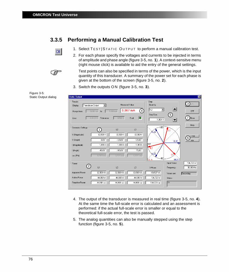
3.3.5 Performing a Manual Calibration Test1. Select T E S T | S T A T I C O U T P U T to perform a manual calibration test.
2. For each phase specify the voltages and currents to be injected in terms of amplitude and phase angle (figure 3-5, no. 1). A context-sensitve menu (right mouse click) is available to aid the entry of the general settings.
Test points can also be specified in terms of the power, which is the input quantity of this transducer. A summary of the power set for each phase is given at the bottom of the screen (figure 3-5, no. 2).
3. Switch the outputs O N (figure 3-5, no. 3).Figure 3-5:Static Output dialog
4. The output of the transducer is measured in real time (figure 3-5, no. 4). At the same time the full-scale error is calculated and an assessment is performed: if the actual full-scale error is smaller or equal to the theoretical full-scale error, the test is passed.
5. The analog quantities can also be manually stepped using the step function (figure 3-5, no. 5).
4
2
1
57
3
6
77
Transducer
6. The shortcut buttons can also be used to set the system to certain useful values in the selected characteristic (figure 3-5, no. 6). • +max:The +max button sets the system to output the maximum value
of the characteristic.
• min: The min button sets the system to output the minimum value of the characteristic.
• -max: The -max button sets the system to output the negative maximum value of the characteristic (this button is only displayed for symmetric characteristics).
Note: If the characteristic is a compound characteristic, a +knee button, to set the system to output the value of the kneepoint of the characteristic, is also available (with a corresponding -knee button if the compound characteristic is symmetric).
7. After the manual tests are finished, close the Static Output dialog box (figure 3-5, no. 7).
OMICRON Test Universe
78
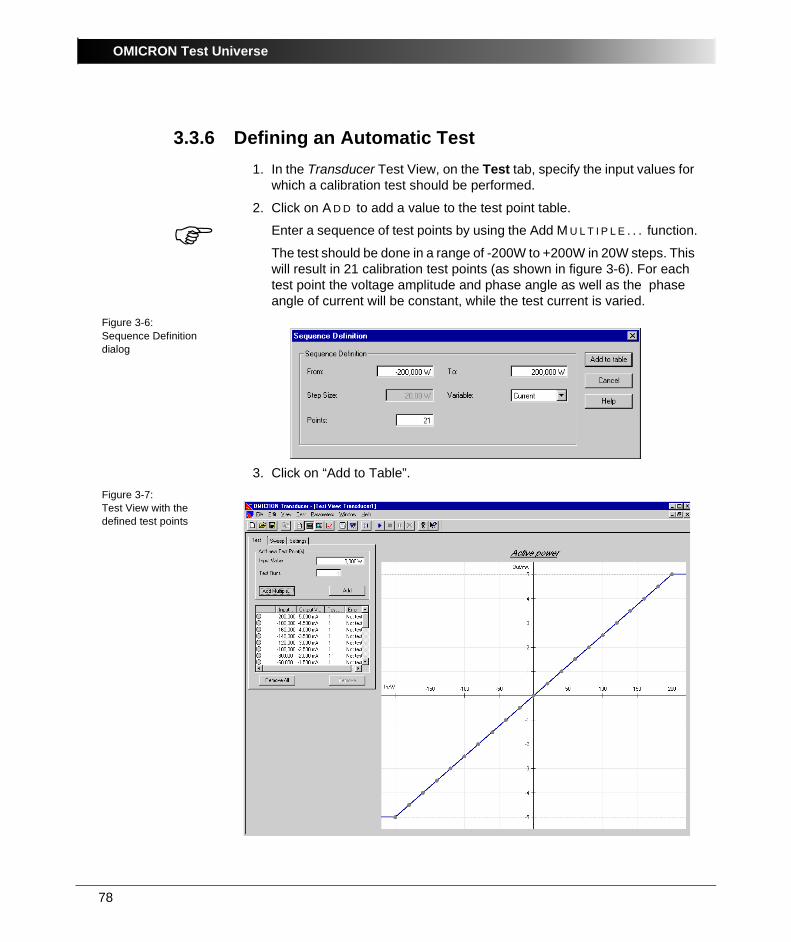
3.3.6 Defining an Automatic Test1. In the Transducer Test View, on the Test tab, specify the input values for
which a calibration test should be performed.
2. Click on A D D to add a value to the test point table.
Enter a sequence of test points by using the Add M U L T I P L E . . . function.
The test should be done in a range of -200W to +200W in 20W steps. This will result in 21 calibration test points (as shown in figure 3-6). For each test point the voltage amplitude and phase angle as well as the phase angle of current will be constant, while the test current is varied.
Figure 3-6:Sequence Definition dialog
3. Click on “Add to Table”.Figure 3-7:Test View with the defined test points
79
Transducer
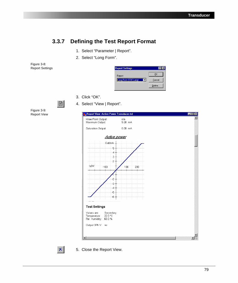
3.3.7 Defining the Test Report Format1. Select “Parameter | Report”.
2. Select “Long Form”.Figure 3-8:Report Settings
3. Click “OK”.
4. Select “View | Report”.Figure 3-9:Report View
5. Close the Report View.
OMICRON Test Universe
80
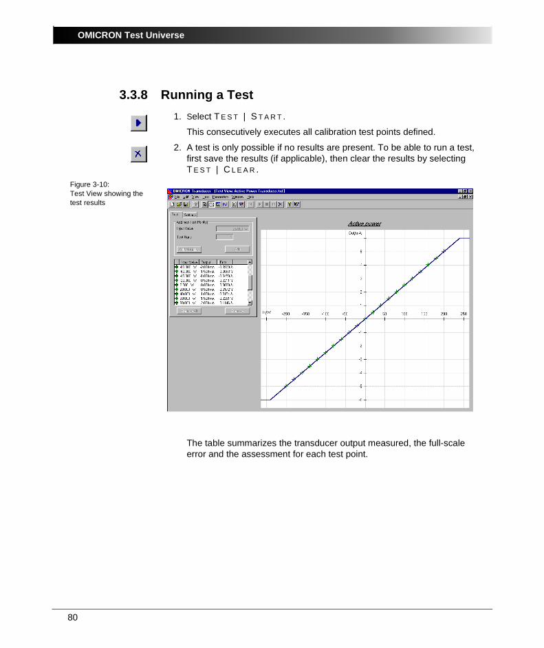
3.3.8 Running a Test1. Select T E S T | S T A R T .
This consecutively executes all calibration test points defined.
2. A test is only possible if no results are present. To be able to run a test, first save the results (if applicable), then clear the results by selecting T E S T | C L E A R .
Figure 3-10:Test View showing the test results
The table summarizes the transducer output measured, the full-scale error and the assessment for each test point.
81
Transducer
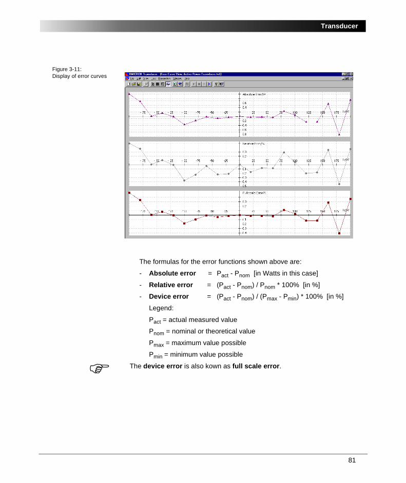
Figure 3-11:Display of error curves
The formulas for the error functions shown above are:
- Absolute error = Pact - Pnom [in Watts in this case]
- Relative error = (Pact - Pnom) / Pnom * 100% [in %]
- Device error = (Pact - Pnom) / (Pmax - Pmin) * 100% [in %]
Legend:
Pact = actual measured value
Pnom = nominal or theoretical value
Pmax = maximum value possible
Pmin = minimum value possible
The device error is also kown as full scale error.

OMICRON Test Universe
82
83
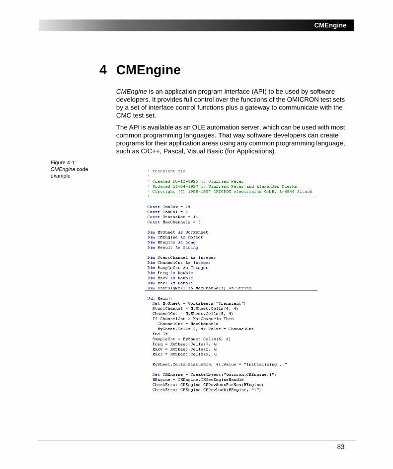
CMEngine
4 CMEngineCMEngine is an application program interface (API) to be used by software developers. It provides full control over the functions of the OMICRON test sets by a set of interface control functions plus a gateway to communicate with the CMC test set.
The API is available as an OLE automation server, which can be used with most common programming languages. That way software developers can create programs for their application areas using any common programming language, such as C/C++, Pascal, Visual Basic (for Applications).
Figure 4-1:CMEngine code example
OMICRON Test Universe
84
In this application program, the CMEngine library is used to communicate with one or more CMC test sets connected to the PC or notebook by means of exchanging string commands.
CMEngine contains string commands to set a CMC to a specific state (e.g. to output a certain voltage) as well as commands to get measurement data or other information from a CMC. The returned information may be analyzed and processed further by the application program.
Since CMEngine is a specific application that is only used by a limited number of advanced users with particular application needs as well as programming knowledge, this Measurement manual does not focus on CMEngine details.
There is an "electronic manual" available, a PDF file named CMEngine.pdf, that was installed with Test Universe (unless deselected during installation). This comprehensive reference documentation describes in detail the CM Engine commands, their syntax and usage.
In the course of the installation of the OMICRON Test Universe software, CMEngine.pdf is copied to your hard disk. If you accepted the default installation folder, it will be situated in
\Program Files\OMICRON\Test Universe\Doc
If you chose a different installation folder, the document is situated in a subfolder named Doc underneath your installation folder.
To read the electronic manual, either
• change to the Windows Explorer, navigate to the Doc folder, and double-click CMengine.PDF
• or
- start the OMICRON Test Universe online help
- in the table of contents navigate to "CMEngine"
- open the topic "About CMEngine" and click the "Click here to view the CM Engine user manual... " hyperlink.
85
Test Tools
5 Test ToolsThe OMICRON Test Universe Test Tools provide additional stand-alone applications for specific testing tasks. You can find them on the Start Page under "Test Tools".
5.1 TransPlayTransPlay is a program that runs independently from the OMICRON Test Universe and its embedded test module concept. It performs playbacks of transient data using a CMC test set. Files of any duration can be played back. The only limitation is the capacity of the hard disk of the PC.
Note: EnerLyzer and TransPlay cannot run in parallel because TransPlay is constantly downloading data and requires all available resources. It is possible to run EnerLyzer and Advanced TransPlay in parallel because Advanced TransPlay downloads the entire signal and then all further processing is done in the test set.
5.1.1 TransPlay Features• Multiple file playback
• Support for transient file formats 16 bit WAV and Comtrade
• Display of transient files data in a time Signal View
• Specification of (external) trigger conditions for starting the playback
• Specification of the playback sampling rate in a range of 1 to 10 kHz
• Specification of transformation ratios and scaling for amplitudes
• Recording of the binary inputs
• Inversion of each channel
OMICRON Test Universe
86
5.1.2 TransPlay ExampleSample files:
• Aa12zf.cfg
• Aa12zf.dat
Stored at:
...OTU installation path\Test Library\Samples\SW Manual Examples\Protection
TaskThe output of a transient signal with three voltage channels and three current channels is required.
The signal is available as a file in COMTRADE format (CFG and DAT file).
SolutionThis example is based on a failure report. The recorded signal has a maximum current of approximately 30 A. Because of this, the current amplifier CMA 156 must be used. This amplifier allows the output of the following maximum current values in one current triple (A or B):
• 25 Arms x = 35.355 Apeak
• or, 70.71 Apeak if both current triples are connected in parallel.
2
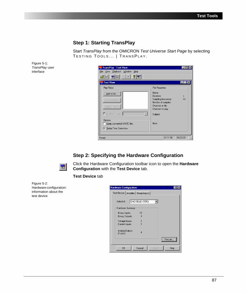
87
Test Tools
Step 1: Starting TransPlayStart TransPlay from the OMICRON Test Universe Start Page by selecting T E S T I N G T O O L S . . . | T R A N S P L A Y .
Figure 5-1:TransPlay user interface
Step 2: Specifying the Hardware ConfigurationClick the Hardware Configuration toolbar icon to open the Hardware Configuration with the Test Device tab.
Test Device tab
Figure 5-2:Hardware configuration: information about the test device
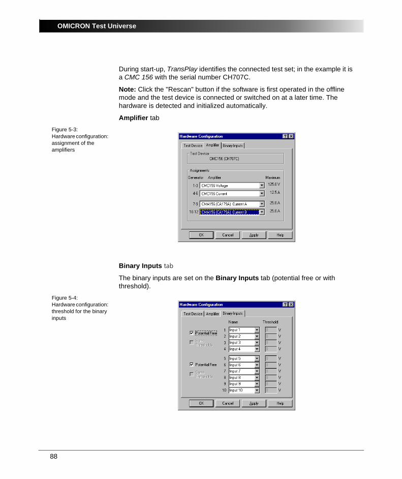
OMICRON Test Universe
88
During start-up, TransPlay identifies the connected test set; in the example it is a CMC 156 with the serial number CH707C.
Note: Click the "Rescan" button if the software is first operated in the offline mode and the test device is connected or switched on at a later time. The hardware is detected and initialized automatically.
Amplifier tabFigure 5-3:Hardware configuration: assignment of the amplifiers
Binary Inputs tab
The binary inputs are set on the Binary Inputs tab (potential free or with threshold).
Figure 5-4:Hardware configuration: threshold for the binary inputs
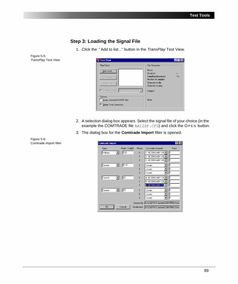
89
Test Tools
Step 3: Loading the Signal File1. Click the " Add to list..." button in the TransPlay Test View.
Figure 5-5:TransPlay Test View
2. A selection dialog box appears. Select the signal file of your choice (in the example the COMTRADE file AA12ZF.CFG) and click the O P E N button.
3. The dialog box for the Comtrade Import filter is opened.Figure 5-6: Comtrade import filter
OMICRON Test Universe
90
In this dialog box you perform the following settings:
• The voltage and current signals (channels) of the Comtrade file have to be assigned to the physical amplifier outputs.
• In the shown example there are one voltage triple with 125 V, one current triple with 12.5 A, and two further current triples with 25 A each.
• Furthermore you may have to enter the transforming ratio of the voltage and/or the current transformer.
This is necessary, if the COMTRADE file contains primary values. In this case, the software already suggests a value.
This example uses secondary values which the selected amplifiers can output over the complete range. Therefore the transforming ratio is 1.
4. Clicking the O K button applies the settings. Now the file is loaded.
During the loading process the signal is converted from the COMTRADE format to the WAV format which is used for audio applications. From now on, this file format is used for all further processes internal to the PC.
5. The file name AA12ZF.WAV is now displayed (see figure 5-7).
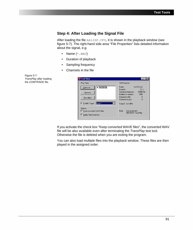
91
Test Tools
Step 4: After Loading the Signal FileAfter loading the file AA12ZF.CFG, it is shown in the playback window (see figure 5-7). The right-hand side area "File Properties" lists detailed information about the signal, e.g.
• Name (*.WAV)
• Duration of playback
• Sampling frequency
• Channels in the fileFigure 5-7:TransPlay after loading the COMTRADE file.
If you activate the check box "Keep converted WAVE files", the converted WAV file will be also available even after terminating the TransPlay test tool. Otherwise the file is deleted when you are exiting the program.
You can also load multiple files into the playback window. These files are then played in the assigned order.

OMICRON Test Universe
92
Step 5: Preparing the Signal OutputBecause the amplifier CMA 156 is being used for the current output in this example, you have to activate the check box "Delay Time Correction" before you play the file.
Without this correction, a phase fault may appear of approximately 2° between the voltage (CMC test set) and the current (amplifier).
Note: This phase fault is corrected automatically and without any user action for the sine-wave output signals of the remaining test modules.
For this example, the signal output should occur on a specific trigger condition.
1. Mark the check box "Enable Trigger" and define "Input 1" as the trigger condition.
If you define the trigger condition "Ext. Trigger", TransPlay waits for a trigger signal from the external CMGPS synchronization unit which is connected to the circular plug on the rear of the CMC test device before it starts the output of the transient signal.
2. Open the Playback Properties dialog box by clicking its toolbar icon.Figure 5-8:TransPlay Playback Properties: General tab
93
Test Tools
General tab
Here you can set the playback frequency of the output. The default setting is the frequency with which the signal was recorded. In most cases the signal will be output with the same frequency. Therefore you can leave this value unchanged.
In practice this could be used for example to adapt a fault occurrence in a 60 Hz mains supply to a 50 Hz mains supply by stretching the time axis with the factor 60/50.
Note: The playback frequency is adjustable between 1 and 100 kHz. But the signals are limited to a maximum of 10 kHz by the test device.
Due to the conversion, values calculated by linear interpolations are added or the sample frequency is reduced to 10,000 per second if the recording frequency was higher.
If there were frequencies higher than 5 kHz included, aliasing effects can occur.
TransPlay loads the converted files (*.WAV) to the transient memory of the CMC test set which outputs the signals.
Note: The file to play should be stored on the hard disk, if possible, to guarantee best load time. Loading from a floppy disk or via a PC network could result in speed problems.
Marking the check box "No Stop on Data Underflow" always continues the signal output even if the connected PC is not able to load the output values to the sample buffer in time.
This is only relevant for very long files or slow computers. The transient memory is able to store temporarily
• 2 k of samples (2048 samples) with 6 output channels or
• 1 k of samples (1024 samples) with 12 output channels.
Marking the check box "Binary Input Recording... Enable" logs all changes on one of the 10 binary inputs to a defined text file, when the signal is played back (e.g. test file BIN.TXT in figure 5-15).

OMICRON Test Universe
94
Invert tab
On the Invert tab you can set a phase shift of 180 degrees for a channel. In this manner, a signal can be inverted.
Figure 5-9:TransPlay Playback Properties: inverting signals
Practical use of this feature: inverting the current flow by changing the starpoint connection (e.g. from Towards Busbar to Towards Line).
This inversion is not used in our example.
CMx15x tabs
On the tabs CMC156 U, CMC156 I, CMA156 IA and CMA156 IB you can change the signal assignment to the amplifier outputs which was initially defined when loading the file.
For this example, the signals were assigned as follows:
• Voltage signals to CMC156 V.
• Current signals to triple A of CMA156 I.Figure 5-10:TransPlay Playback Properties: signal assignment to CMC 156 V

95
Test Tools
Figure 5-11:TransPlay Playback Properties: signal assignment to CMC 156 I
Figure 5-12:TransPlay Playback Properties: signal assignment to CMA 156 IA
Figure 5-13:TransPlay Playback Properties: signal assignment to CMA 156 IB
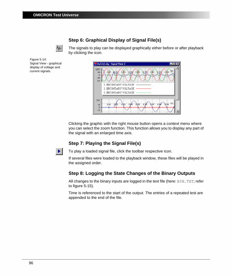
OMICRON Test Universe
96
Step 6: Graphical Display of Signal File(s)The signals to play can be displayed graphically either before or after playback by clicking the icon.
Figure 5-14:Signal View - graphical display of voltage and current signals.
Clicking the graphic with the right mouse button opens a context menu where you can select the zoom function. This function allows you to display any part of the signal with an enlarged time axis.
Step 7: Playing the Signal File(s)To play a loaded signal file, click the toolbar respective icon.
If several files were loaded to the playback window, these files will be played in the assigned order.
Step 8: Logging the State Changes of the Binary OutputsAll changes to the binary inputs are logged in the text file (here: BIN.TXT; refer to figure 5-15).
Time is referenced to the start of the output. The entries of a repeated test are appended to the end of the file.
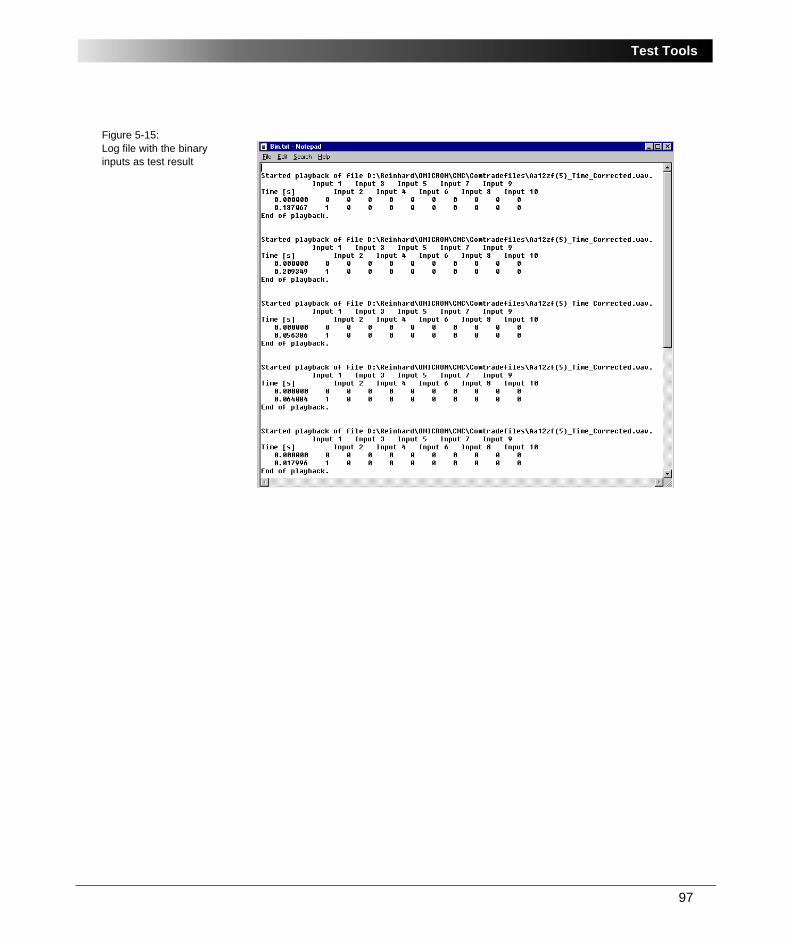
97
Test Tools
Figure 5-15:Log file with the binary inputs as test result
OMICRON Test Universe
98
5.2 HarmonicsHarmonics allows to create a signal sequence consisting of a pre-signal with fundamental frequency, followed by a signal with definable spectral combination (all harmonics up to 3 kHz if supported by the connected hardware), followed by a post-signal with fundamental frequency.
Harmonics can generate up to three currents and three voltages, each with individual harmonics composition.
The duration of all three parts of the signal sequence can be defined. Furthermore, the middle part can react on a binary input signal ('trip signal') that leads to a direct transition to the post-signal and a time measurement of the trip time.
Besides generating this signal sequence live you may also output the harmonics composition as static state, i.e. manually controlled duration, or export it as Comtrade file set for separate playback, e.g. with the TransPlay tool or the Advanced TransPlay test module.
For more detailled information about Harmonics, please refer to its online help. Start Harmonics and click the Help Topics command on the H E L P pull-down menu.
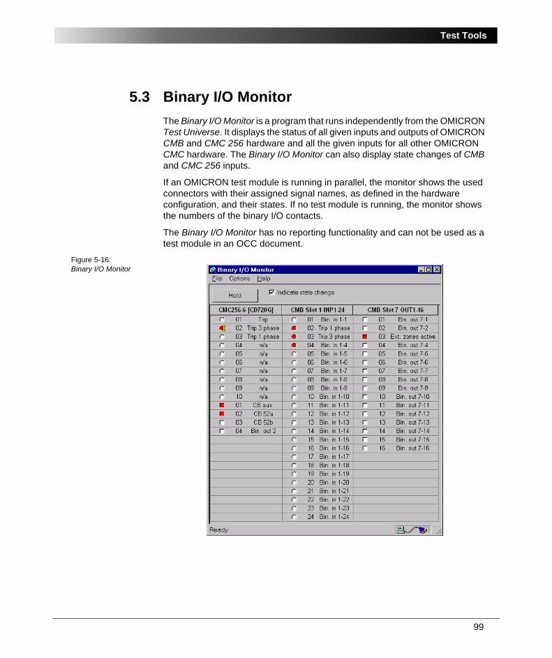
99
Test Tools
5.3 Binary I/O MonitorThe Binary I/O Monitor is a program that runs independently from the OMICRON Test Universe. It displays the status of all given inputs and outputs of OMICRON CMB and CMC 256 hardware and all the given inputs for all other OMICRON CMC hardware. The Binary I/O Monitor can also display state changes of CMB and CMC 256 inputs.
If an OMICRON test module is running in parallel, the monitor shows the used connectors with their assigned signal names, as defined in the hardware configuration, and their states. If no test module is running, the monitor shows the numbers of the binary I/O contacts.
The Binary I/O Monitor has no reporting functionality and can not be used as a test module in an OCC document.
Figure 5-16:Binary I/O Monitor
OMICRON Test Universe
100
5.3.1 Features of the Binary I/O MonitorBinary I/O Monitor provides the following functions:
• It displays the status of all given inputs and outputs of OMICRON CMB and CMC 256 hardware and all the given inputs for all other OMICRON CMC hardware.
• It displays as many I/O connectors as are detected.
• Binary I/O Monitor displays all available inputs and outputs in a grid: one column for the CMC I/O connectors and one column for each CMB card. Each column has one row for each connector.
• The columns are manually resizable, and Binary I/O Monitor will save these settings from session to session.
• If the user does not specify column settings, the columns are automatically resized at start-up to fit the length of the connector label.
• The user can zoom in and out on the display on the context-sensitive menu.
• Each input and output is identified with the same name given in the hardware configuration from the test module that runs in parallel (e.g., 01 Start L1, 04 Trip L1, etc.).
• The state of each connector is indicated with a small symbol: a circle indicates an input and a square indicates an output. If the symbol is white, it means that the connector is inactive (0); if it is red, it means that the connector is active (1); if it is grey, it means that the state is not available. If the check box "Indicate state changes" has been selected, a small yellow arrow is shown to indicate that a change of the binary status was detected.
5.3.2 Using Binary I/O MonitorBinary I/O Monitor has one button, labelled H O L D , which freezes the display of the current states, and a check box, "Indicate state changes." At start-up, the H O L D button is released and the check box is cleared.
When the "Indicate state changes" check box is selected, each change of a CMB or CMC 256 input (from 0 to 1 or from 1 to 0) is indicated by a yellow arrow beside the current state information. Each change will continue to be indicated until the H O L D button is pressed, or until the check box is cleared.
Note: Only the state changes of CMB or CMC 256 inputs can be displayed; the state changes of any other CMC inputs are never indicated by a yellow arrow.
101
Test Tools
Pressing the H O L D button freezes the display of the current states and state change information. As well, if the "Indicate state changes" checkbox has been selected, pressing the H O L D button will clear and disable it. Once pressed, the H O L D button label changes to R E S E T . Pressing the H O L D / R E S E T button a second time releases the display and Binary I/O Monitor once again displays the current states of the connectors.
5.3.3 Context MenuBinary I/O Monitor offers several options via the context-sensitive menu. This menu can be displayed by right-clicking anywhere on the I/O grid. The context-sensitive menu offers two display options: zoom and automatic resize of the columns.
ZoomZ O O M allows the user either to shrink the display (Z O O M O U T ) so that more columns and inputs/outputs are visible in the Binary I/O Monitor window, or to enlarge the display (Z O O M I N ). When the display is enlarged, fewer columns may be visible, but the information displayed will be more legible. This is useful on screens with a very high resolution.
By right-clicking anywhere on the I/O grid, the user can access the zoom menu’s three options: I N , O U T and 1 0 0 % . Selecting "I N " zooms in on the display. Selecting "O U T " zooms out on the display. Selecting "1 0 0 % " restores the display to the default view.
The last zoom setting is saved when the program exits. The next time the Binary I/O Monitor is launched it will display the I/O grid with the same zoom setting.
Automatic ResizeThe A U T O M A T I C R E S I Z E option is used to fit the width of the columns of the I/O grid table to the length of the longest input/output label. This ensures that all labels are completely displayed.
The A U T O M A T I C R E S I Z E option is located at the bottom of the context-sensitive menu. This option can be activated by right-clicking anywhere on the I/O grid and then selecting A U T O M A T I C R E S I Z E . A checkmark will appear next to the option to indicate that it is active.
The column widths can also be adjusted manually. When the pointer is moved over the line between two columns, it changes to a double-headed arrow.
OMICRON Test Universe
102
Clicking the column boundary and dragging in the wanted direction will resize the column. When the column sizes are resized manually, the A U T O M A T I C R E S I Z E option is deselected and the columns sizes are saved when the the program exits. The next time Binary I/O Monitor is launched it will display the columns with the same width.
5.3.4 Options MenuThe O P T I O N S menu, the second of the Binary I/O Monitor’s three pull-down menus, has two display-related choices: A L W A Y S O N T O P , and U P D A T E S P E E D .
Always on TopThe A L W A Y S O N T O P option is used to keep the Binary I/O Monitor always in the foreground of the screen, even if another window has the focus. This option is useful if the user wishes to work in another window but continue to monitor the activity of Binary I/O Monitor.
The A L W A Y S O N T O P option can be activated by clicking the A L W A Y S O N T O P option on the O P T I O N S pull-down menu. A checkmark will appear next to the option to indicate that it is active.
Update SpeedThe U P D A T E S P E E D option allows the user to set the speed at which the Binary I/O Monitor is updated. The Binary I/O Monitor, like all applications, draws on the computer’s resources. If the PC slows down because of insufficient resources, reducing the speed at which Binary I/O Monitor is updated can free system resources for other tasks.
The update speed can be changed by clicking U P D A T E on the O P T I O N S pull-down menu. This will open a submenu with three update speeds: low, medium (the default update speed) and high. The current update speed is indicated by a checkmark.
Note: The CPU load of the PC depends on the number of displayed inputs and outputs and on the update speed. Therefore, the update speed can be improved, while at the same time reducing the use of system resources, by zooming in or reducing the window size to display only the columns necessary.
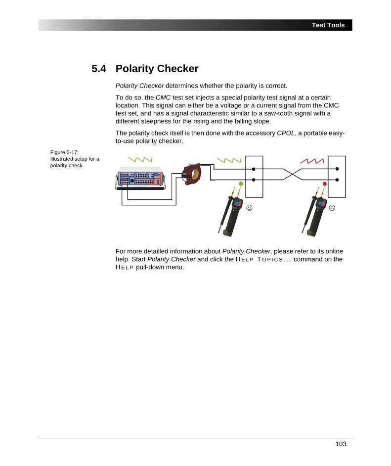
103
Test Tools
5.4 Polarity CheckerPolarity Checker determines whether the polarity is correct.
To do so, the CMC test set injects a special polarity test signal at a certain location. This signal can either be a voltage or a current signal from the CMC test set, and has a signal characteristic similar to a saw-tooth signal with a different steepness for the rising and the falling slope.
The polarity check itself is then done with the accessory CPOL, a portable easy-to-use polarity checker.
Figure 5-17:Illustrated setup for a polarity check
For more detailled information about Polarity Checker, please refer to its online help. Start Polarity Checker and click the H E L P T O P I C S . . . command on the H E L P pull-down menu.
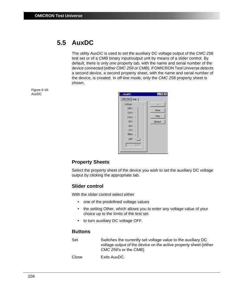
OMICRON Test Universe
104
5.5 AuxDCThe utility AuxDC is used to set the auxiliary DC voltage output of the CMC 256 test set or of a CMB binary input/output unit by means of a slider control. By default, there is only one property tab, with the name and serial number of the device connected (either CMC 256 or CMB). If OMICRON Test Universe detects a second device, a second property sheet, with the name and serial number of the device, is created. In off-line mode, only the CMC 256 property sheet is shown.
Figure 5-18:AuxDC
Property SheetsSelect the property sheet of the device you wish to set the auxiliary DC voltage output by clicking the appropriate tab.
Slider controlWith the slider control select either
• one of the predefined voltage values
• the setting Other, which allows you to enter any voltage value of your choice up to the limits of the test set
• to turn auxiliary DC voltage OFF.
ButtonsSet Switches the currently set voltage value to the auxiliary DC
voltage output of the device on the active property sheet (either CMC 256's or the CMB).
Close Exits AuxDC.
105
Test Tools
Help Calls up the AuxDC online help.
Default Makes the currently set voltage value the power-up default for the device on the active page (either CMC 256 or CMB). When CMC 256 or CMB is powered-up the next time, the auxiliary DC output is automatically set to this default value.
This default values applies until it is deliberately changed again.
Setting a power-up default value means, that immediately after CMC 256 or CMB is switched on, this voltage is applied to the auxiliary DC voltage output, regardless whether a PC is connected to it or not.
Caution: This voltage can be life-threatening!
OMICRON Test Universe
106
5.6 License ManagerLicense Manager combines the functionality of a license browser, a merge tool and a license file editor. It searches for OMICRON license files stored on the computer's hard disk(s) and displays their contents. It merges license information from different files into the master license file Omicron.lic. It furthermore allows to add license keys manually.
To start License Manager, click the License Manager link on the Start Page under "Setup".
5.6.1 About License Files in GeneralThe OMICRON Test Universe software is protected from unauthorized installation and use by a license file.
The license file codes specify both the individual test modules and the hardware serial numbers, i.e., each code specifies a pair of "test module X to work with test set A". The license code enabling test module X to work with test set A will differ from the code for test set B, even though A and B might be the same CMC model.
The master license file Omicron.lic is automatically installed to [Common Files]\OMICRON.
[Common Files] holds the full path to the folder defined by Windows to store files shared by applications that are installed on the system. In English Windows, that folder is named "Common Files" and is located in the [Program Files] folder. In other language versions of Windows, the common files folder name is localized appropriately by default.
Omicron.lic is an ASCII text file that can be viewed with any text editor.
If you purchase additional OMICRON test sets at a later point of time, you need to add their license codes, provided in separate license files, to the master license file. To do so, use the utility License Manger.
5.6.2 Finding License Files• Enter the search path into the entry field "Search in" and click "Search".
License Manager automatically searches through this folder and all of its subfolders. If you want to search through an entire hard disk, just enter its drive letter, e.g., C:\. The "Search in" combo box saves the most recent selections.
or
• Click "Browse" to navigate through the folder structure. Select a folder of your choice and click "Search".
107
Test Tools
All found license files(s) is / are listed in the upper list field.
The master license file does not have to be searched. As long as it is physically present on the hard disk, it is always displayed.
5.6.3 Contents of a License FileClick a license file of your choice in the upper list field.
• The lower left-hand side list field shows the devices (test sets) the file contains, and their according serial numbers.
• The lower right-hand side list field displays the keys that belong to each device selected in the left-hand side list field. Each key represents exactly one test module licensed to work with the selected device.
5.6.4 Merging License Files into the Master License FileCorresponding menu item: F I L E | O P E N F I L E A N D M E R G E …
Navigate through the folder structure and select a license file of your choice. The selected file as a whole is merged into the master license file Omicron.lic; the new keys are appended. Double entries in the master license file are prevented: if a key already exists, the new one replaces it.
Corresponding menu item: E D I T | M E R G E F I L E
In the upper list field select any license file of your choice but the master license file. The selected license file as a whole is merged into the master license file; the new keys are appended. Double entries in the master license file are prevented: if a key already exists, the new one replaces it.
Note: Contents merging is unidirectional, i.e., only merging from any license file into the master license file is possible, not vice versa. Therefore, depending on the selected license file, this button and the corresponding menu items may be disabled.
Corresponding menu item: E D I T | D E L E T E F I L E
Deletes the selected license file. Caution: Also the master license file can be deleted that way. Deleted files cannot be restored from the Windows Recycle Bin.
OMICRON Test Universe
108
5.6.5 Merging Single Devices and Keys Into the Master License FileCorresponding menu items: E D I T | M E R G E D E V I C E ( M E R G E K E Y )
Select either a device in the lower left-hand side list field or a key in the lower right-hand side list field and click the according icon. The selected device or key is merged into the master license file. Double entries in the master license file are prevented: if a device with that serial number or a key with that license code already exists, the new one replaces it.
Corresponding menu item: E D I T | D E L E T E D E V I C E ( D E L E T E K E Y )
Deletes the selected device or key from the master license file. Caution: Deleted items cannot be restored.
Note: Only master license file entries can be deleted. Therefore, depending on the selected license file, this button and the corresponding menu items may be disabled.
5.6.6 Context MenusIn all list fields, a right mouse click opens a context-menu. The context-menu items correspond to the toolbar and pull-down menu commands. They either merge entire license files (in the upper list field), or selected devices or keys (lower list fields) into the master license files. Deletion is also provided.
With the context-menu item A D D L I C E N S E K E Y (corresponding pull-down menu item: E D I T | A D D L I C E N S E K E Y … ) you specify a new pair "test set A licensed to work with test module X". To do so, you need a valid device serial number and test module license code. Note: A new license key can only be added to the master license file. Therefore, depending on the selected license file, the respective menu items may be disabled.
5.6.7 Sorting the Displayed DataIn the two lower list fields the displayed data can be sorted to show the data in ascending order by device type, serial numbers or module names. To do so, click the respective header (e.g., Device).
109
Test Tools
5.6.8 Show Only Licenses With VersionStarting with Test Universe 2.0, a "license code versioning" is introduced. Adding the TU version number to a license key permits the user to store identical license keys for different TU versions in one master license file. This master license file can then be used on different computers with different TU versions without the necessity to exchange master license files beforehand.
This combo box represents a display filter: Specify whether all available license keys of the particular file are displayed (default) or just the ones according to your version selection.
5.6.9 Sending Your Master License File to OMICRON by E-MailIn case you need to send you master license file to the OMICRON support for an analysis, select the pull-down menu item F I L E | S E N D M A S T E R L I C E N S E F I L E … . This hands over a copy of your master license file to the standard e-mail application of this computer. If there isn't such an application, the Windows Internet Connection Wizard will start.

OMICRON Test Universe
110
File Name Extensions within OMICRON Test Universe
File Name Extensions within OMICRON Test Universe
Control Center OCCfilename.OCC OMICRON Control Center test document
OCC Helper Modulesfilename.PAU Pause Module
filename.EXQ ExeCute
filename.TXV TextView
Hardware Configurationfilename.OHC OMICRON Hardware Configuration (import/export
from HCW’s General tab)
Test Objectfilename.RIO The term RIO stands for Relay Interface by
OMICRON.
RIO, was developed out of a need for a uniform data format for parameters of protective relays produced by different manufacturers. RIO provides a common structure to allow functionally similar relays from diverse manufacturers to be tested with similar test procedures. Moreover, RIO permits relay characteristics to be imported into the Test Universe software from external sources.
filename.XRIO XRIO represents the second generation of RIO file technology. The term RIO stands for Relay Interface by OMICRON, a technology that was already available with previous Test Universe versions. The X denotes "extended".
125
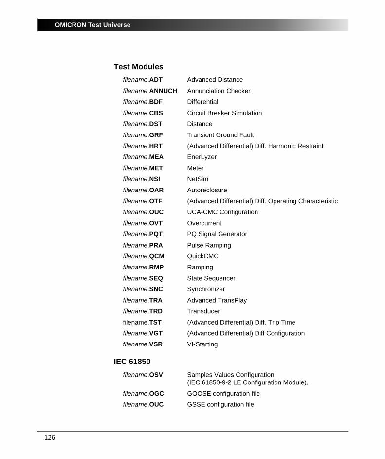
OMICRON Test Universe
Test Modulesfilename.ADT Advanced Distance
filename ANNUCH Annunciation Checker
filename.BDF Differential
filename.CBS Circuit Breaker Simulation
filename.DST Distance
filename.GRF Transient Ground Fault
filename.HRT (Advanced Differential) Diff. Harmonic Restraint
filename.MEA EnerLyzer
filename.MET Meter
filename.NSI NetSim
filename.OAR Autoreclosure
filename.OTF (Advanced Differential) Diff. Operating Characteristic
filename.OUC UCA-CMC Configuration
filename.OVT Overcurrent
filename.PQT PQ Signal Generator
filename.PRA Pulse Ramping
filename.QCM QuickCMC
filename.RMP Ramping
filename.SEQ State Sequencer
filename.SNC Synchronizer
filename.TRA Advanced TransPlay
filename.TRD Transducer
filename.TST (Advanced Differential) Diff. Trip Time
filename.VGT (Advanced Differential) Diff Configuration
filename.VSR VI-Starting
IEC 61850filename.OSV Samples Values Configuration
(IEC 61850-9-2 LE Configuration Module).
filename.OGC GOOSE configuration file
filename.OUC GSSE configuration file
126

File Name Extensions within OMICRON Test Universe
Test Toolsfilename.BIO Binary I/O Monitor
filename.HOU Harmonics
filename.LST TransPlay
filename.TYP TypConverter
Other file name extension to know aboutfilename.CFG COMTRADE configuration file for the description of
the failure report channels (signal names, sample frequency etc.). Can be imported with the test module Advanced TransPlay, and loaded with the (optional) test tool TransView.
filename.CML Comtrade file. Can be loaded with the (optional) test tool TransView.
filename.CSV Comma Separated Value. This file format is readable by any common database. Data is written in simple a table format. A selectable field delimiter separates the individual values.
If a certain value is a text string, the value needs to have a text qualifier (the text may contain the character which is used a field delimiter). As the naming of Boolean values is not consistent throughout different database programs, the True and False values need to be defined as well.
filename.DAT COMTRADE file with the sample values of the failure report channels. Can be imported with the test module Advanced TransPlay, and loaded with the (optional) test tool TransView.
filename.HDR "Header file" that contains any data-related text that is not used by the software. Can be loaded with the test module Advanced TransPlay
127
OMICRON Test Universe
filename.PDF Invented by Adobe, Portable Document Format became the standard format for the electronic document distribution and exchange. PDF files look exactly like original documents and preserve the fonts, images, graphics, and layout of any source file - regardless of the application and platform used to create it.
To view a PDF file, either the Adobe Reader © or the Foxit Reader (both freeware) is required. If you have no PDF reader on your computer yet, OMICRON Test Universe installs the Foxit Reader.
filename.PL4 PL4 file. Can be imported with the test module Advanced TransPlay, and loaded with the (optional) test tool TransView.
filename.RTF Rich Text Format. File format used by Microsoft Word or other word processing applications.
filename.TPL Template file for the test reports (based on RTF)
filename.TRF TRF file. Can be imported with the test module Advanced TransPlay, and loaded with the (optional) test tool TransView.
filename.XML XML (eXtensible Markup Language) became accepted as a standard for data exchange, particularly between different platforms. XML and related technologies are W3C (World Wide Web Consortium) recommendations.
If you want to learn more about XML, the W3C site http://www.w3.org/XML/ may be a good starting point.
128
41
Contact Information / Technical Support
Contact Information / Technical Support
Europe, Africa, Middle EastOMICRON electronics GmbH
Phone: + 43 5523 507-333
E-Mail: [email protected]
Web: www.omicron.at
Asia, PacificOMICRON electronics Asia Ltd, Hong Kong
Phone: +852 2634 0377
E-Mail: [email protected]
Web: www.omicron.at
North and South AmericaOMICRON electronics Corp. USA
Phone: +1 713 830-4660 or 1 800 OMICRON
E-Mail: [email protected]
Web: www.omicronusa.com
For addresses of OMICRON offices with customer service centers, regional sales offices or offices for training, consulting and commissioning please see our website.

Contact Information / Technical Support
42

117
Index
Index
Aabsolute error
Transducer . . . . . . . . . . . . . . . . . . . . . . . . 81Active Power Transducer
test example . . . . . . . . . . . . . . . . . . . . . . 73address
OMICRON address . . . . . . . . . . . . . . . . 115API
CMEngine . . . . . . . . . . . . . . . . . . . . . . . . 83Application program interface
CMEngine . . . . . . . . . . . . . . . . . . . . . . . . 83AuxDC (test tool) . . . . . . . . . . . . . . . . . . . . . 104AuxDC Utility . . . . . . . . . . . . . . . . . . . . . . . . . 11
BBinary I/O Monitor test tool . . . . . . . . . . . . . . 10
CCB Configuration. Refer to Circuit Breaker ConfigurationCFG file format . . . . . . . . . . . . . . . . . . . . . . . 91Circuit Breaker Configuration . . . . . . . . . . . . 10CM Engine . . . . . . . . . . . . . . . . . . . . . . . . . . 11CMC 256
AuxDC voltage . . . . . . . . . . . . . . . . . . . . 104CMC256
testing a multifunctional electronic meter with the Meter module . . . . . . . . . . . . . . . 38
CMEngineintroduction . . . . . . . . . . . . . . . . . . . . . . . 83location of electronic manual . . . . . . . . . . 84
COMTRADEfile name extension CML . . . . . . . . . . . . 113TransPlay test tool . . . . . . . . . . . . . . . . . 86
contact informationOMICRON address . . . . . . . . . . . . . . . . 115
Control Center (OCC)overview . . . . . . . . . . . . . . . . . . . . . . . . . . 9
CPOL polarity checker . . . . . . . . . . . . . . . . 103
Ddevice error
Transducer . . . . . . . . . . . . . . . . . . . . . . . 81
Ee-mail
OMICRON address . . . . . . . . . . . . . . . . 115Error curves
in Transducer . . . . . . . . . . . . . . . . . . . . . 81examples
Active Power Transducer . . . . . . . . . . . . 73ExeCute (OCC Helper Module) . . . . . . . . . . . 9
Ffile
CFG format (Transplay test tool) . . . . . . . 91file name extensions . . . . . . . . . . . . . . . 111format WAV (Transplay test tool) . . . . . . 91
Frequency Trip Contact of a Multifunctional Transducer . . . . . . . . . . . . . . . . . . . . . . . . . . 15
OMICRON Test Universe
118
Hhardware configuration . . . . . . . . . . . . . . . . . 16
for Active Power transducer example . . . 75for testing a multifunctional electronic meter with the Meter module . . . . . . . . . . 56for testing an electromechanical meter with a reference meter with the Meter module . . . . . . . . . . . . . . . . . . . . . . . . . . . 39
Harmonics test tool . . . . . . . . . . . . . . . . . . . . 10hotline . . . . . . . . . . . . . . . . . . . . . . . . . . . . . 115
LLicense Manager . . . . . . . . . . . . . . . . . . . . . . 11
MMeter
lapse of a meter test . . . . . . . . . . . . . . . . 22multifunctional meter . . . . . . . . . . . . . . . . 21types of meters that can be tested . . . . . . 21
meter class . . . . . . . . . . . . . . . . . . . . . . . . . . 21meter test
lapse . . . . . . . . . . . . . . . . . . . . . . . . . . . . 22various test modes . . . . . . . . . . . . . . . . . . 22
Meter test module . . . . . . . . . . . . . . . . . . . . . 10modes for the Meter module . . . . . . . . . . . . . 22
Oonline help . . . . . . . . . . . . . . . . . . . . . . . . . . . 84
PPause Module (OCC Helper Module) . . . . . . . 9PDF
file name extension . . . . . . . . . . . . . . . . 114Polarity Checker . . . . . . . . . . . . . . . . . . . . . 103Polarity Checker test tool . . . . . . . . . . . . . . . 11
QQuickCMC . . . . . . . . . . . . . . . . . . . . . . . 13, 15
measurement example . . . . . . . . . . . . . . 15nature of the test task . . . . . . . . . . . . . . . 15wiring . . . . . . . . . . . . . . . . . . . . . . . . . . . . 16
QuickCMC test module . . . . . . . . . . . . . . . . 10
Rrelative error
Transducer . . . . . . . . . . . . . . . . . . . . . . . 81report format
State Sequencer . . . . . . . . . . . . . . . . . . . 35RIO
file name extension . . . . . . . . . . . . . . . . 111
119
Index
SSample file
Frequency Trip Contact of a Multifunctional Transducer example . . . . . . . . . . . . . . . . 15Testing a Multifunctional Electronical Meter example . . . . . . . . . . . . . . . . . . . . . 53Testing a Static CT/PT - Operated Meter 24Testing an Electromechanical Meter . . . . 36Transducer example . . . . . . . . . . . . . . . . 73
sample fileTransPlay example . . . . . . . . . . . . . . . . . 86
startTransducer . . . . . . . . . . . . . . . . . . . . . . . . 75
State Sequencerreport format . . . . . . . . . . . . . . . . . . . . . . 35
Ttechnical support . . . . . . . . . . . . . . . . . . . . . 115test
Active Power Transducer . . . . . . . . . . . . . 73Meter examples . . . . . . . . . . . . . . . . . . . . 24testing a multifunctional electronic meter with the Meter module . . . . . . . . . . . . . . . 53testing an electromechanical meter with a reference meter with the Meter module 36
test modes for the Meter module . . . . . . . . . 22test report
saving the test report for later use 35, 52, 67test set-up
for testing a multifunctional electronic meter with the Meter module . . . . . . . . . . 55for testing an electromechanical meter with a reference meter with the Meter module . . . . . . . . . . . . . . . . . . . . . . . . . . . 38
test toolAuxDC . . . . . . . . . . . . . . . . . . . . . . . . . . 104
test toolsTransPlay . . . . . . . . . . . . . . . . . . . . . . 10, 85
Test Wizard . . . . . . . . . . . . . . . . . . . . . . . . . . . 9
Testing a Multifunctional Electronical Meter example . . . . . . . . . . . . . . . . . . . . . . . . . . . . 53Testing a Static CT/PT - Operated Meter example . . . . . . . . . . . . . . . . . . . . . . . . . . . . 24Testing an Electromechanical Meter example . . . . . . . . . . . . . . . . . . . . . . . . . . . . 36TextView (OCC Helper Module) . . . . . . . . . . . 9Transducer
Active Power Transducer test . . . . . . . . . 73automatic test . . . . . . . . . . . . . . . . . . . . . 78error curves . . . . . . . . . . . . . . . . . . . . . . . 81hardware configuration . . . . . . . . . . . . . . 75introduction . . . . . . . . . . . . . . . . . . . . . . . 69manual calibration test . . . . . . . . . . . . . . 76running the Active Power Transducer test 80sample file for Active Power Transducer example . . . . . . . . . . . . . . . . . . . . . . . . . . 73start . . . . . . . . . . . . . . . . . . . . . . . . . . . . . 75starting Transducer . . . . . . . . . . . . . . . . . 75wiring to CMC test set . . . . . . . . . . . . . . . 74
Transducer test module . . . . . . . . . . . . . . . . 10transient signal
with 3 voltage & 4 current channels (TransPlay) . . . . . . . . . . . . . . . . . . . . . . . 86
TransPlaytest tool . . . . . . . . . . . . . . . . . . . . . . . 10, 85
WWAV file (Transplay test tool) . . . . . . . . . . . . 91wiring
QuickCMC . . . . . . . . . . . . . . . . . . . . . . . . 16
XXML
file name extension . . . . . . . . . . . . . . . . 114XRIO
file name extension . . . . . . . . . . . . . . . . 111

OMICRON Test Universe
120