omnivergent stereo - waypoint
TRANSCRIPT

Omnivergent Stereo
Heung-Yeung ShumVision Technology Group
Microsoft ResearchRedmond, WA 98052
Adam KalaiDepartment of Computer Science
Carnegie Mellon UniversityPittsburgh, PA 15213
Steven M. Seitz�
The Robotics InstituteCarnegie Mellon University
Pittsburgh, PA 15213
AbstractThe notion of a virtual sensor for optimal 3D reconstruc-tion is introduced. Instead of planar perspective images thatcollect many rays at a fixed viewpoint, omnivergent cam-eras collect a small number of rays at many different view-points. The resulting 2D manifold of rays are arranged intotwo multiple-perspective images for stereo reconstruction.We call such images omnivergent images, and the processof reconstructing the scene from such images omnivergentstereo. This procedure is shown to produce 3D scene mod-els with minimal reconstruction error, due to the fact thatfor any point in the 3D scene, two rays with maximum ver-gence angle can be found in the omnivergent images. Fur-thermore, omnivergent images are shown to have horizontalepipolar lines, enabling the application of traditional stereomatching algorithms, without modification. Three types ofomnivergent virtual sensors are presented: spherical om-nivergent cameras, center-strip cameras and dual-strip cam-eras.
1 IntroductionPlanar perspective images have long been the primary sub-strate of computer vision algorithms, due to the ease of ac-quiring such images from conventional cameras. The lastfew years, however, have seen a growing interest in funda-mentally new types of image representations for a varietyof applications in computer vision and computer graphics.Such new representations include mosaics [1, 2, 3, 4] thatencode radiance information from all angles converging ata single optical center, as well as non-perspective represen-tations like light fields [5], lumigraphs [6], multiperspec-tive panoramas [7], and manifold mosaics [8]. These newimage representations can be derived from one or more con-ventional images or acquired directly from new imaging de-vices, e.g., catadioptic cameras [9]. In the former case, wecan think of derived images as representing the output of avirtual sensor with certain characteristics.
� The support of a grant from the Microsoft Corporation is gratefully ac-knowleged. Part of this work was conducted while Steven Seitz was em-ployed by the Vision Technology Group at Microsoft Research.
The emergence of these new types of images suggestsa powerful new paradigm for solving computer visionproblems–rather than adapting the algorithm to suit the im-age, we can modify the image to best suit the algorithm.This approach has a powerful advantage: it becomes possi-ble to boost the performance of a specific vision algorithmor even an entire class of algorithms by providing inputdata that is carefully crafted to improve the performanceof the target algorithm(s). To demonstrate this approach, inthis paper we formulate a new type of virtual sensor that isspecifically designed to optimize the performance of stereoreconstruction algorithms.
Our approach is motivated by the fact that perspectiveimage sequences are poorly suited as input for 3D recon-struction tasks for a variety of reasons. First, image se-quences are highly redundant and represent scene appear-ance in a form that is difficult to process. Second, stor-ing, transmitting, and processing long image sequences athigh-resolution is cumbersome and computationally expen-sive on today’s computer workstations. Third, traditionaland multi-baseline stereo algorithms do not easily scale tohandle hundreds or thousands of input images. In contrast,an ideal sensor would sample scene radiance in a mannerthat is designed to optimize the task of scene reconstruction.Furthermore, images from such a sensor would be amenableto efficient processing with scanline stereo algorithms.
To accomplish these objectives, we introduce a virtualsensor called an omnivergent camera that has the followingproperties:
� Omnivergence: every point in the scene is imagedfrom two cameras that are vergent on that point (seeFig. 1) with maximum vergence angle. This strategy isshown to simultaneously optimize the reconstructionaccuracy of every point in the scene.
� Uniform Accuracy: scene radiance is sampled uni-formly in all directions, yielding isotropic depth res-olution. In contrast, stereo reconstructions obtainedfrom planar or panoramic [10, 11] images are shownto generate strongly biased (non-isotropic) scene re-constructions.

� Compactness: radiance information from hundreds orthousands of input images is distilled into two or morecomposite images, thereby reducing an N-view recon-struction problem to a binocular stereo matching task,with minimal loss of accuracy.
� Boosting Property: due to their linear epipolar geom-etry, omnivergent images may be used directly as inputto existing stereo algorithms, providing an algorithm-independent mechanism for optimizing reconstructionaccuracy.
The idea behind the omnivergent camera is as follows,suppose you are given the task of providing two images asinput to a binocular stereo matching algorithm, with the ob-jective of obtaining the most accurate possible scene recon-struction. Suppose further that you can acquire images fromas many viewpoints as you like, but may store at most a two-dimensional set of pixels (viewing rays) from which to con-struct the two images (note that the space of all viewing raysis five-dimensional [10]). Finally, you should construct im-ages that satisfy the constraints of most stereo algorithms,i.e., epipolar lines should correspond to horizontal lines inthe image.
Given this objective, which viewpoints and viewing rayswould you select to form your images? In this paper, wedemonstrate that the answer can be obtained on a point-by-point basis: for each 3D scene point P, we wish to choosethe best pair of views from which to reconstruct P. Givencertain assumptions, these views correspond to the twocameras that are vergent on P and for which the vergenceangle is maximized. This strategy can be shown to yielda 2D manifold of rays that, when arranged into two im-ages, produce the best possible stereo reconstruction. Thesetwo images can be thought of as an omnivergent stereo pair,output from a virtual sensor that is simultaneously vergenton every point in the scene. We call such images omniver-gent panoramas, and the process of reconstructing the scenefrom such images omnivergent stereo.
This work was inspired by recent work on stereo frompanoramas [10, 11]. The beauty of the panoramic stereo ap-proach is that the same class of algorithms that have proveneffective for binocular stereo reconstruction can also pro-duce 360Æ reconstructions, simply by changing the input tothe algorithm. However, stereo on panoramas has some crit-ical shortcomings–first the epipolar geometry for cylindri-cal panoramas is nonlinear, significantly complicating thestereo search procedure [10]. Second, and more important,we shall see that stereo on panoramic images does not pro-duce a fair reconstruction (accuracy is good in some regionsbut extremely poor in others). These two limitations areremedied by the omnivergent approach set forth in this pa-per.
Two of the mosaic representations presented in this pa-
Voxel
Beam
Vergenceangle
Pixel
P
Figure 1: To reconstruct a point P with minimal uncer-tainty, the omnivergent sensor captures two beams of maxi-mal vergence angle that contain P .
per, namely the center-strip and dual-strip varieties, wereindependently discovered by Peleg and Ben-Ezra [12] forthe purpose of creating stereo panoramas for scene visual-ization. A similar stereo panorama representation based onrotating a stereo head was previously proposed by Huangand Hung [13]. In both of these approaches, an explicit 3Dmodel is not computed, rather the images are visually fusedwith stereo glasses to achieve a stereo effect. In contrast,our objective is to obtain an explicit 3D scene reconstruc-tion using stereo matching algorithms.
In the remainder of this paper, we describe the omniver-gent stereo approach in detail. Section 2 introduces the om-nivergent approach for the case of a 2D camera confinedto move within a circular region of the plane. Sections 3and 4 generalize the analysis to 3D where a camera movesalong a sphere and a circle, respectively. Section 5 presentsa practical implementation by taking two symmetrical off-centered slit images from a regular camera rotating arounda circle. Several examples of omnivergent images are given,with results of processing these images with existing stereoalgorithms. The paper concludes with a summary and fu-ture work.
2 Omnivergent Imaging
Suppose you can move a camera anywhere within somefixed region of space, with the objective of reconstructingthe scene outside of that region as accurately as possible.Suppose further that you can acquire images from as manyviewpoints as you like, but may store only a fixed num-ber of pixels, due to limitations in resources. Which pixelswould you save and from which cameras? In this section,we study the case of a camera moving within a circular re-gion of the plane, depicted in Fig. 1. In order to accuratelylocalize a point P , we argue that it is best to choose a pairof cameras that are vergent on P with maximum vergenceangle. By choosing different cameras to reconstruct differ-ent scene points, it is possible to model virtual sensor that

is simultaneously vergent on every point on the scene.In this section, we introduce the omnivergent virtual sen-
sor, which maximizes the vergence angle for all points inthe scene, and compare its performance to other plausiblesensors for the specific case of a camera viewpoints withina circle. A theoretical justification for why maximizing ver-gence angle is desirable is given in the appendix. In ourterminology, a pixel captures a beam of rays, as shown inFig. 1, and the direction of the beam is defined to be its an-gle bisector. The intersection of two beams is a voxel and avirtual sensor with resolution N denotes a collection of Nbeams.
The central idea behind binocular stereo algorithms isthat the location of a point in the world is identified bytriangulation from corresponding pixels in two input im-ages. Each pixel corresponds to a beam of viewing raysthat project to a finite region of the image plane. Given twopixels in correspondence, one can deduce that the true lo-cation of the point is in a particular voxel, corresponding tothe intersections of the two pixel beams (Fig. 1). This voxelrepresents the uncertainty of the reconstruction, since thepoint may lie anywhere within the voxel region. For pur-poses of visualization, it is convenient to assume that thepoint is at the center of the voxel, corresponding to the in-tersection of the two beam directions.
By plotting the voxel centers for a specified camera con-figuration, we can visualize the spatial sampling of a par-ticular virtual sensor and the quality of the resulting recon-struction. Note that if we limit the number of beams (pixels)toN , there is a finite number of possible beam intersectionsand thus a finite number of voxels. To begin with, con-sider the traditional binocular stereo configuration, of twocameras oriented in a parallel or vergent configuration. Acritical shortcoming of this configuration is that it enablesreconstructing only the subset of the scene that is in front ofthe cameras. A recently proposed solution is to use two ormore panoramic cameras [10, 11] instead. We can modelsuch a pair of panoramic images as representing the outputof a single sensor with two focal points.
Fig. 2(b) shows the voxel centers for the binocularpanoramic sensor used in [10, 11], with 180 beams total.Clearly, this approach yields very biased reconstructions, asthe voxels are distributed highly non-uniformly. In particu-lar, the portion of the scene that lies near the line betweenthe two camera centers is reconstructed with relatively pooraccuracy, where the distance between voxel centers is muchhigher than in other parts of the scene.
To improve uniformity, a natural idea would be to usethree cameras, as shown in Fig. 2(c-d). While the resultingdistribution of voxels is somewhat more uniform than thebinocular case, some portions of the plane are now coveredby three beams and others by two, yielding an uneven dis-tribution of voxels. Fig. 2(e-f) captures only the rays of the
VoxelCenter
Camera 1
Camera 2
−30 −20 −10 0 10 20 30−30
−20
−10
0
10
20
30
(a) (b)
−20 0 20
−20
0
20
(c) (d)
−20 0 20
−20
0
20
(e) (f)
−20 0 20
−20
0
20
(g) (h)
Figure 2: Each virtual sensor at left represents a configura-tion of pixel ray directions from cameras on a circle. Theintersections of these rays define a lattice of voxels whosecenters are shown at right. In each case, the sensor has 180pixels total. (a) corresponds to a panoramic binocular cam-era rig and (g) to an omnivergent sensor. (g) Incoming lightsensed along the rays tangent to a circle can be recorded intwo separate 1D images, one for the clockwise and one forthe counter-clockwise rays. Performing stereo matching onthese two omnivergent images yields a reconstruction withoptimal characteristics.

P
φ
Cφ
Πφ
L
(a) (b)
L X
Y
Figure 3: Construction of spherical omnivergent images.For any scene point P , we wish to choose a pair of camerasin the sphere vergent on P with maximal vergence angle.To achieve this goal, it is sufficient choose a revolute axisL of the sphere and capture rays along the longitude lines(a). (b) For any scene point P , there exists a pair of lon-gitude rays vergent on P for which the vergence angle ismaximized over the entire sphere.
exterior angles of the triangle spanned by the three opticalcenters. This configuration covers every point in the sceneby exactly two beams, and its voxel centers are more evenlydistributed. If we extend this idea to a regular n-gon insteadof a triangle, then for n = N we get the omnivergent sensor.Note that for a fixed number of beams, the number of voxelscan vary for different sensors, due to the fact that not everypair of beams will intersect. For the four sensors depictedin the figure, the total number of voxels are approximately2000, 3000, 3200, and 4000, respectively.
2.1 Omnivergent Images
The omnivergent sensor of resolution N captures two setsof N=2 beams, evenly spaced around the circle, pointing inthe direction of the tangents. Half of these we call forwardand the other half backward tangents, according to whetherthe ray points in the clockwise or counter clockwise direc-tion, respectively (Fig. 2(g)). Recording the forward tan-gents in one image and the backward tangents in anotheryields two one-dimensional omnivergent images. A corre-spondence between pixels in these two images can be ob-tained using standard stereo matching algorithms (restrictedto a 1D search). For any two pixels that correspond, weknow precisely which two beams are stored in these pixels,and straightforward trigonometry locates the voxel of theintersection between these two beams, yielding the recon-struction and its associated uncertainty.
The omnivergent sensor has three key advantages: first, itgives uniform angular accuracy over the entire scene. Sec-ond, it reduces the N -view stereo problem to a binocu-lar stereo problem, amenable to conventional stereo algo-rithms. Third, it provides a mechanism for maximizing thevergence angle for every point in the scene.
3 Spherical Omnivergent Stereo
In this section we generalize the analysis of 2D camera mo-tion to 3D camera motion within a spherical volume. Thestatement of the problem is similar to the planar case: sup-pose you could move a camera anywhere within a closedsphere and acquire as many images as you like. For anygiven point P in the scene, you would like to choose a pairof rays vergent on P such that the vergence angle is maxi-mized. For any two pointsX and Y in the sphere, we definethe vergence angle to be 6 PXY .
It is easily seen that the desired set of rays are tangent tothe sphere. For any given point P , the set of all rays from P
that graze the sphere defines a circle KP where these raysintersect the sphere. The vergence angle is maximized bychoosing any pair of rays on opposite poles of KP :
Spherical Vergence Property: Let S be a spherewith center C and let P be a point outside S.6 PXY is maximized for all points X and Y inS when X and Y are on KP and X;Y; P; and Care co-planar.
If we allow P to vary over the entire scene, it is evidentthat capturing the incoming light along all tangent rays tothe sphere is sufficient to image every point in the scenewith two rays having maximum vergence angle. Note thatthe set of all tangent rays is three-dimensional—in contrast,the set of all rays from points within the sphere is four-dimensional. Therefore, we can obtain a 3D omnivergentimage by storing tangent rays in a volumetric data struc-ture. While some stereo algorithms have been developed toprocess 3D image volumes [14, 15], storing and processing3D images poses a daunting task. Fortunately, it is possi-ble to further reduce the dimensionality to a 2D set of rays,which we demonstrate next using a constructive argument.
Observe that a sphere can be generated by rotating a cir-cle 180
Æ about an axis L passing through the center of thecircle. The resulting set of circles correspond to the longi-tude lines of a globe with polar axisL, as shown in Fig. 3(a).Each circle C� lies in a plane ��, and the set of all suchplanes defines a one-parameter family of circles about Lcalled a pencil [14]. Now consider a point P outside thesphere. P must lie in at least one plane in the pencil; let ��
be one such plane1. Consider the two rays from P that aretangent to C�. Let X and Y be the two tangency points onC�. Note that these two rays are also tangent to the sphereand thereforeX and Y lie onKP . Since,X;Y and P all lieon ��, a plane that passes through the center of the sphere,it follows from the vergence property that these two raysyield the maximum possible vergence angle for all rays inthe sphere.
1Points on L lie on all planes in the pencil.
C
P0
P
V1
V2
(a) (b)
forwardrays
backwardrays φ
θ
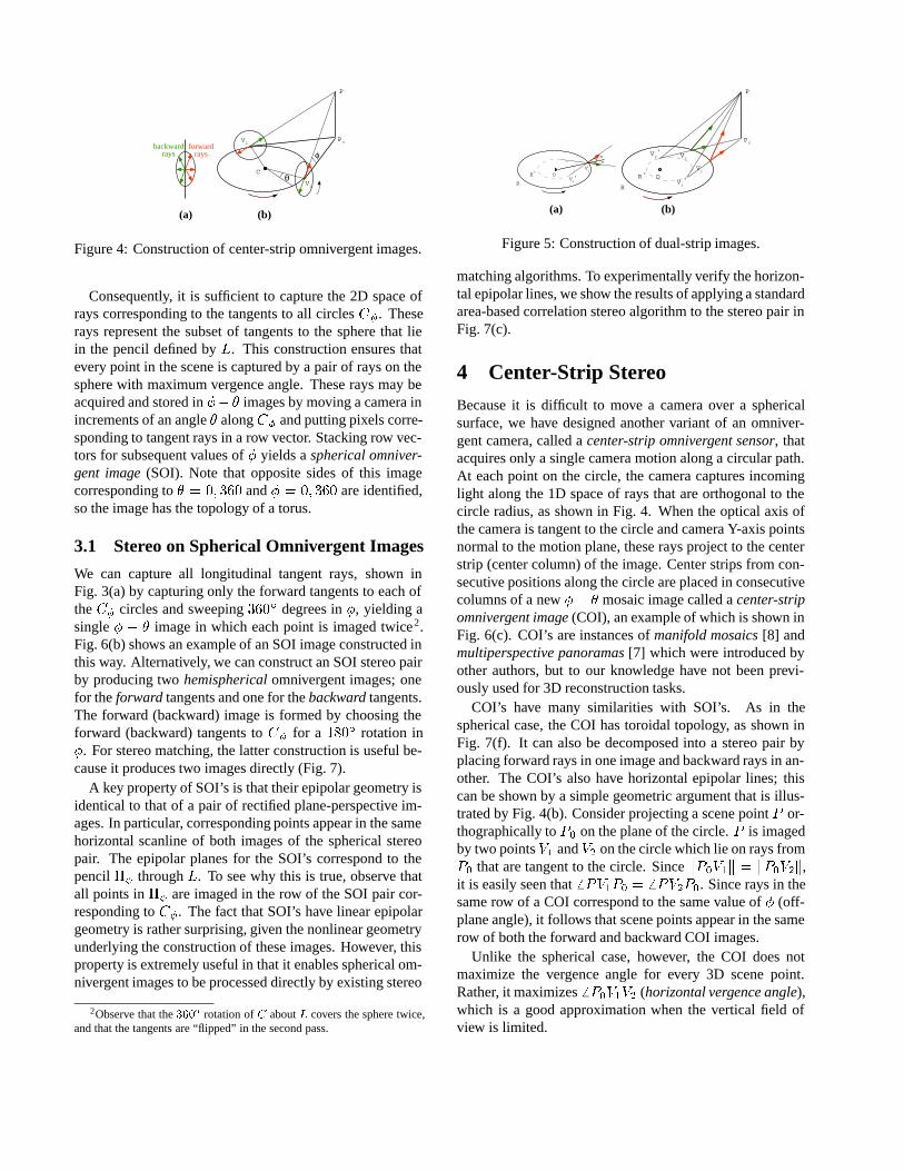
Figure 4: Construction of center-strip omnivergent images.
Consequently, it is sufficient to capture the 2D space ofrays corresponding to the tangents to all circles C�. Theserays represent the subset of tangents to the sphere that liein the pencil defined by L. This construction ensures thatevery point in the scene is captured by a pair of rays on thesphere with maximum vergence angle. These rays may beacquired and stored in �� � images by moving a camera inincrements of an angle � along C� and putting pixels corre-sponding to tangent rays in a row vector. Stacking row vec-tors for subsequent values of � yields a spherical omniver-gent image (SOI). Note that opposite sides of this imagecorresponding to � = 0; 360 and � = 0; 360 are identified,so the image has the topology of a torus.
3.1 Stereo on Spherical Omnivergent Images
We can capture all longitudinal tangent rays, shown inFig. 3(a) by capturing only the forward tangents to each ofthe C� circles and sweeping 360
Æ degrees in �, yielding asingle � � � image in which each point is imaged twice2.Fig. 6(b) shows an example of an SOI image constructed inthis way. Alternatively, we can construct an SOI stereo pairby producing two hemispherical omnivergent images; onefor the forward tangents and one for the backward tangents.The forward (backward) image is formed by choosing theforward (backward) tangents to C� for a 180
Æ rotation in�. For stereo matching, the latter construction is useful be-cause it produces two images directly (Fig. 7).
A key property of SOI’s is that their epipolar geometry isidentical to that of a pair of rectified plane-perspective im-ages. In particular, corresponding points appear in the samehorizontal scanline of both images of the spherical stereopair. The epipolar planes for the SOI’s correspond to thepencil �� through L. To see why this is true, observe thatall points in �� are imaged in the row of the SOI pair cor-responding to C�. The fact that SOI’s have linear epipolargeometry is rather surprising, given the nonlinear geometryunderlying the construction of these images. However, thisproperty is extremely useful in that it enables spherical om-nivergent images to be processed directly by existing stereo
2Observe that the 360Æ rotation of C about L covers the sphere twice,and that the tangents are “flipped” in the second pass.
O
P0
P
V1
V2
V2'
V1'R'
R
OV1
V1'R'
R
aa
(a) (b)
Figure 5: Construction of dual-strip images.
matching algorithms. To experimentally verify the horizon-tal epipolar lines, we show the results of applying a standardarea-based correlation stereo algorithm to the stereo pair inFig. 7(c).
4 Center-Strip Stereo
Because it is difficult to move a camera over a sphericalsurface, we have designed another variant of an omniver-gent camera, called a center-strip omnivergent sensor, thatacquires only a single camera motion along a circular path.At each point on the circle, the camera captures incominglight along the 1D space of rays that are orthogonal to thecircle radius, as shown in Fig. 4. When the optical axis ofthe camera is tangent to the circle and camera Y-axis pointsnormal to the motion plane, these rays project to the centerstrip (center column) of the image. Center strips from con-secutive positions along the circle are placed in consecutivecolumns of a new � � � mosaic image called a center-stripomnivergent image (COI), an example of which is shown inFig. 6(c). COI’s are instances of manifold mosaics [8] andmultiperspective panoramas [7] which were introduced byother authors, but to our knowledge have not been previ-ously used for 3D reconstruction tasks.
COI’s have many similarities with SOI’s. As in thespherical case, the COI has toroidal topology, as shown inFig. 7(f). It can also be decomposed into a stereo pair byplacing forward rays in one image and backward rays in an-other. The COI’s also have horizontal epipolar lines; thiscan be shown by a simple geometric argument that is illus-trated by Fig. 4(b). Consider projecting a scene point P or-thographically to P0 on the plane of the circle. P is imagedby two points V1 and V2 on the circle which lie on rays fromP0 that are tangent to the circle. Since kP0V1k = kP0V2k,it is easily seen that 6 PV1P0 = 6 PV2P0. Since rays in thesame row of a COI correspond to the same value of � (off-plane angle), it follows that scene points appear in the samerow of both the forward and backward COI images.
Unlike the spherical case, however, the COI does notmaximize the vergence angle for every 3D scene point.Rather, it maximizes 6 P0V1V2 (horizontal vergence angle),which is a good approximation when the vertical field ofview is limited.
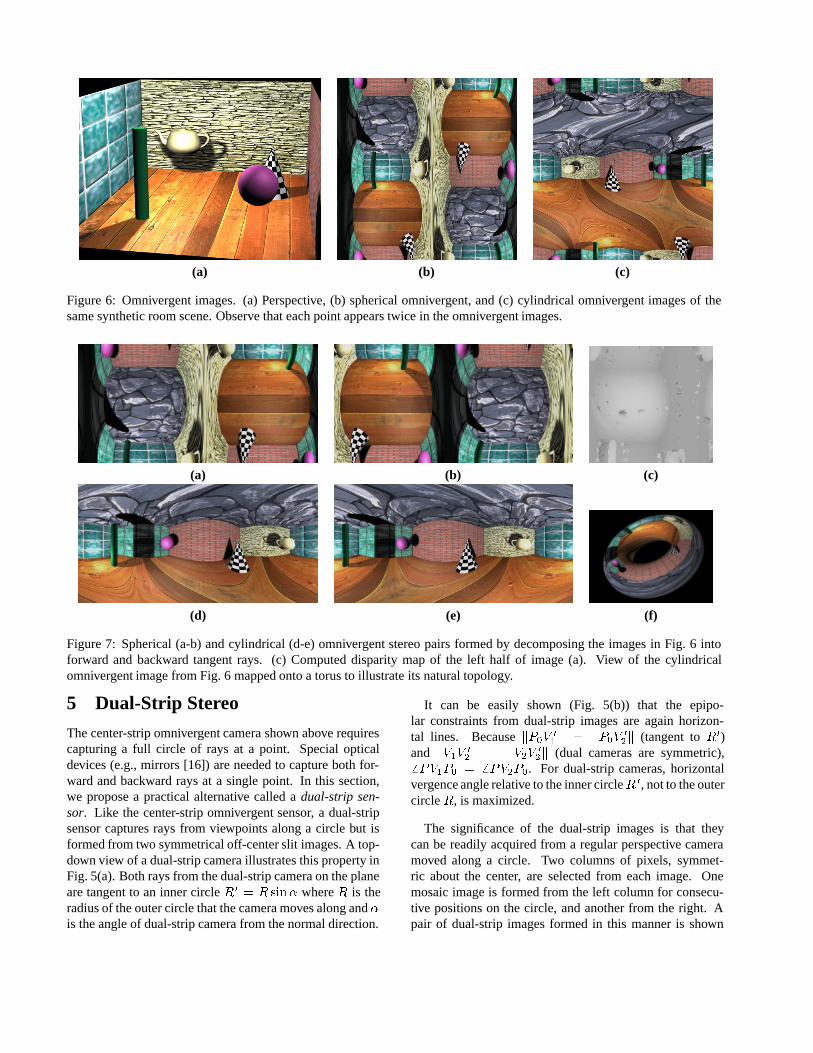
(a) (b) (c)
Figure 6: Omnivergent images. (a) Perspective, (b) spherical omnivergent, and (c) cylindrical omnivergent images of thesame synthetic room scene. Observe that each point appears twice in the omnivergent images.
(a) (b) (c)
(d) (e) (f)
Figure 7: Spherical (a-b) and cylindrical (d-e) omnivergent stereo pairs formed by decomposing the images in Fig. 6 intoforward and backward tangent rays. (c) Computed disparity map of the left half of image (a). View of the cylindricalomnivergent image from Fig. 6 mapped onto a torus to illustrate its natural topology.
5 Dual-Strip Stereo
The center-strip omnivergent camera shown above requirescapturing a full circle of rays at a point. Special opticaldevices (e.g., mirrors [16]) are needed to capture both for-ward and backward rays at a single point. In this section,we propose a practical alternative called a dual-strip sen-sor. Like the center-strip omnivergent sensor, a dual-stripsensor captures rays from viewpoints along a circle but isformed from two symmetrical off-center slit images. A top-down view of a dual-strip camera illustrates this property inFig. 5(a). Both rays from the dual-strip camera on the planeare tangent to an inner circle R 0
= R sin� where R is theradius of the outer circle that the camera moves along and �is the angle of dual-strip camera from the normal direction.
It can be easily shown (Fig. 5(b)) that the epipo-lar constraints from dual-strip images are again horizon-tal lines. Because kP0V
0
1k = kP0V
0
2k (tangent to R0)
and kV1V0
2k = kV2V
0
2k (dual cameras are symmetric),
6 PV1P0 = 6 PV2P0. For dual-strip cameras, horizontalvergence angle relative to the inner circleR 0, not to the outercircle R, is maximized.
The significance of the dual-strip images is that theycan be readily acquired from a regular perspective cameramoved along a circle. Two columns of pixels, symmet-ric about the center, are selected from each image. Onemosaic image is formed from the left column for consecu-tive positions on the circle, and another from the right. Apair of dual-strip images formed in this manner is shown

Figure 8: Dual-strip images formed by moving a single perspective camera 360 Æ on a circle and building mosaics from the60th column (top) and 260th column (bottom) of the input image sequence.
in Fig. 8. These images were created by stacking the 60th
and 260th columns, respectively, from a sequence of 1350frames (with resolution of 320 � 240) taken by a regulardigital video camera. These two images have significanthorizontal parallax but no vertical parallax due to the linearepipolar geometry.
6 Conclusions
Based on the belief that traditional perspective images arenot best suited for solving many computer vision tasks, thispaper introduced the concept of a virtual sensor. A key ideabehind this approach is that it enables optimizing the inputto computer vision algorithms in order to produce superiorresults. Toward this end, we introduced a new family ofsensor called omnivergent sensors that are simultaneouslyvergent on every point in the scene, with maximum ver-gence angle. These sensors are ideally suited for the task of3D reconstruction. Rather than physically construct thesesensors, we described how to create omnivergent images byprocessing a sequence of perspective input images.
Omnivergent images represent scene appearance simulta-neously from numerous perspective viewpoints, as opposedto traditional single perspective images, and are constructedso that the vergence angle for any 3D point is maximized.Consequently, omnivergent stereo produces accurate 3Dscene models with minimal reconstruction error. Further-more, omnivergent images have horizontal epipolar geome-try, enabling the direct application of conventional binocu-lar stereo algorithms for determining pixel correspondence.
We presented three different flavors of omnivergent sen-sors. The first is a spherical omnivergent sensor that sat-isfies the maximum vergence angle property. The secondis a center-strip sensor that maximizes only the horizontalvergence angle, but is more straightforward to implementin practice. The center-strip omnivergent sensor is a goodchoice when the scene is relatively far away and the verti-cal field of view is limited. We also presented a dual-strip
sensor that can be easily implemented by moving a regularcamera on a circle.
There remain several important topics to be further stud-ied. First, in this paper we considered only the problem ofbinocular stereo–better results may be obtained in practiceby formulating an N -ocular stereo problem [17]. Becausethe omnivergent cameras have maximum vergence angle,stereo matching with omnivergent images is more sensitiveto lighting changes than narrow baseline stereo images. Ad-ditional images may be generated by choosing more off-tangent rays and/or choosing different sets of input view-points [18]. Second, the generalization of the circle andsphere case to arbitrary camera paths and surfaces is an im-portant topic of future work. Some of the analysis gen-eralizes to any smooth surface–i.e., saving tangent rays issufficient to maximize the vergence angle. The choice ofcamera path should ideally depend on a priori informationabout scene occupancy. Lastly, we are investigating how tobuild real devices that implement the omnivergent sensorspresented in this paper in hardware, using mirrors to collectfront and backwards rays with a single CCD.
References[1] R. Kumar, P. Anandan, M. Irani, J. Bergen, and K. Hanna,
“Representation of scenes from collections of images,” inProc. IEEE Workshop on Representation of Visual Scenes,pp. 10–17, 1995.
[2] S. Mann and R. Picard, “Virtual bellows: Constructing high-quality images from video,” in Proc. First Int. Conf. on Im-age Processing, 1994.
[3] R. Szeliski, “Video mosaics for virtual environments,” IEEEComputer Graphics and Applications, vol. 16, no. 2, pp. 22–30, 1996.
[4] S. E. Chen, “Quicktime VR — An image-based approachto virtual environment navigation,” in Proc. SIGGRAPH 95,pp. 29–38, 1995.
[5] M. Levoy and P. Hanrahan, “Light field rendering,” in Proc.SIGGRAPH 96, 1996.

[6] S. J. Gortler, R. Grzeszczuk, R. Szeliski, and M. F. Cohen,“The lumigraph,” in Proc. SIGGRAPH 96, pp. 43–54, 1996.
[7] D. N. Wood, A. Finkelstein, J. F. Hughes, C. E. Thayer, andD. H. Salesin, “Multiperspective panoramas for cel anima-tion,” in Proc. SIGGRAPH 97, pp. 243–250, 1997.
[8] S. Peleg and J. Herman, “Panoramic mosaics by manifoldprojection,” in Proc. Computer Vision and Pattern Recogni-tion Conf., pp. 338–343, 1997.
[9] S. Baker and S. Nayar, “A theory of catadioptric imageformation,” in Proc. Sixth Int. Conf. on Computer Vision,pp. 35–42, 1998.
[10] L. McMillan and G. Bishop, “Plenoptic modeling,” in Proc.SIGGRAPH 95, pp. 39–46, 1995.
[11] S. B. Kang and R. Szeliski, “3-D scene data recovery usingomnidirectional multibaseline stereo,” in Proc. ComputerVision and Pattern Recognition Conf., pp. 364–370, 1996.
[12] S. Peleg and M. Ben-Ezra, “Stereo panorama with a singlecamera,” in Proc. Computer Vision and Pattern RecognitionConf., pp. 395–401, 1999.
[13] H. C. Huang and Y. P. Hung, “Panoramic stereo imaging sys-tem with automatic disparity warping and seaming,” Graph-ical Models and Image Processing, vol. 60, no. 3, pp. 196–208, 1998.
[14] R. C. Bolles, H. H. Baker, and D. H. Marimont, “Epipolar-plane image analysis: An approach to determining structurefrom motion,” Int. J. of Computer Vision, vol. 1, no. 1, pp. 7–55, 1987.
[15] A. Katayama, K. Tanaka, T. Oshino, and H. Tamura, “Aviewpoint dependent stereoscopic display using interpola-tion of multi-viewpoint images,” in Proc. SPIE Vol. 2409A,pp. 21–30, 1995.
[16] V. Nalwa, “A true omnidirectional viewer,” tech. rep., BellLabs, Holmodel, NJ, Feb 1996.
[17] M. Okutomi and T. Kanade, “A multiple-baseline stereo,”IEEE Trans. on Pattern Analysis and Machine Intelligence,vol. 15, no. 4, pp. 353–363, 1985.
[18] H.-Y. Shum and R. Szeliski, “Stereo reconstruction frommultiperspective panoramas,” in Proc. Seventh Int. Conf. onComputer Vision, (Kerkyra, Greece), September 1999.
[19] E. Krotkov, K. Henriksen, and R. Kories, “Stereo rangingwith verging cameras,” IEEE Trans. on Pattern Analysis andMachine Intelligence, vol. 12, no. 12, pp. 1200–1205, 1990.
[20] S. Kang, J. Webb, L. Zitnick, and T. Kanade, “A multibase-line stereo system with active illumination and real-time im-age acquisition,” in Proc. Fifth Int. Conf. on Computer Vi-sion, pp. 88–93, 1995.
AppendixVergent stereo rigs have been shown to obtain better stereoreconstructions than parallel rigs for objects near the ver-gence point (e.g., [19, 20]). But why is maximizing ver-gence angle desirable? In this section we provide justifi-cation for maximizing the vergence angle that holds for anarbitrarily shaped connected region X of camera positions.
Suppose two beams intersect at points P and Q, defin-ing two corners of a voxel, and that both P and Q lie out-
QP
X
Top Bottom
S
R
D
B CA
P Q
Figure 9: Maximum vergence gives the smallest voxel withcorners P and Q.
side the convex hull of X , as shown in Fig. 9. We claimthat maximizing vergence angle approximately minimizesthe area and perimeter among voxels with corners P andQ,and this approximation becomes perfect as the number ofbeams goes to infinity. While this does not prove that theomnivergent sensor is optimal for a finite set of beams, itdemonstrates that it performs extremely well as the resolu-tion increases.
We can choose many different pairs of beams from withinX that result in a voxel with P and Q as corners, and eachof these voxels actually has two different vergence angles:one at the top corner (R) and one at the bottom corner (S),as shown in the figure. Now if we decrease the distance be-tween P and Q, i.e., by decreasing the width of the beams,the top and bottom vergence angles become closer, and, inthe limit, are equal. Thus, if we chose to maximize the ver-gence angle between the two angle bisectors of the beams,we are approximately maximizing the top and bottom ver-gence angles, and this approximation gets better as the num-ber of pixels increases.
Let the two tangents to X that pass through P intersectX at A and C. Similarly, let the two tangents to X thatpass through Q intersect X at B and D. By construction,PRQS is the intersection of all beams from points in Xthat contain both P and Q. Consequently, PRQS musthave smaller area and perimeter than any voxel containingP andQ. Note, however, that PRQS is not the intersectionof two pixel beams originating from within the circle. Alsonotice that 6 PRQ is the maximum top vergence angle forany voxel, while 6 PSQ is the maximum bottom vergenceangle. So, we see that placing the beams’ bases at A andD maximizes the top vergence angle, while placing themat B and D maximize the bottom vergence angle. Thesecorrespond to minimizing the areas of triangles PRQ andPSQ, respectively. As the number of pixels in increased,P and Q converge to the same point, as do A and B, sothat in the limit, maximizing the vergence angle producesthe smallest possible voxel.