omniview remote ip manager - belkin · 1-2 features overview overview • remote access the ripm...
TRANSCRIPT
User Manual
Control your computer or KVM switch through a web browser—from anywhere
OmniView® Remote IP Manager
F1DE101H
Control
1. Overview ........................................................................................................................1
1-1 Introduction and Package Contents ..................................................................1
1-2 Features Overview .............................................................................................2
1-3 Equipment Requirements ..................................................................................4
1-4 Systems Supported ...........................................................................................5
1-5 Specifications ....................................................................................................6
1-6 Remote IP Manager Diagram ............................................................................7
2. Installation ....................................................................................................................8
2-1 Hardware Installation .........................................................................................9
2-2 Device Setup ...................................................................................................12
2-3 Software Installation ........................................................................................13
2-4 Configuration via Serial Interface .....................................................................14
2-5 Using your Remote IP Manager .......................................................................15
3. The Remote Console ....................................................................................................16
3-1 Login to the Remote IP Manager .....................................................................16
3-2 Remote IP Manager Interface ..........................................................................17
3-3 Mouse, Keyboard, and Video Configuration ....................................................18
• Remote IP Manager USB Interface ..............................................................18
• Remote IP Manager Keyboard Settings .......................................................18
• Remote-Mouse Settings ..............................................................................18
• Auto-Mouse-Speed and Mouse Synchronization ........................................19
• Host System Mouse Settings ......................................................................20
• Recommended Mouse Settings ..................................................................21
• Navigation ...................................................................................................22
3-4 Remote Console Control Bar ...........................................................................22
3-5 Remote Console Status Line ...........................................................................23
• Resetting the Remote IP Manager to Factory Settings ................................31
• Logout of the Remote IP Manager ..............................................................31
4. Menu Options ...............................................................................................................32
4-1 Remote Control ...............................................................................................32
• KVM Console ...............................................................................................32
• Telnet Console .............................................................................................32
4-2 Virtual Media ....................................................................................................34
• Floppy Disk ..................................................................................................34
• CD-ROM Image ...........................................................................................35
• Drive Redirection .........................................................................................38
• Options ........................................................................................................40
4-3 User Management ...........................................................................................42
• Change Password .......................................................................................43
• Users ...........................................................................................................44
Table of Contents
4-4 KVM Settings ...................................................................................................44
• User Console ...............................................................................................45
• Keyboard/Mouse .........................................................................................48
• Video ...........................................................................................................50
• KVM Ports ...................................................................................................51
4-5 Device Settings ................................................................................................52
• Network .......................................................................................................52
• Dynamic DNS ..............................................................................................54
• Security .......................................................................................................56
• Certificate ....................................................................................................58
• Serial Port ....................................................................................................60
• Intelligent Platform Management Interface (IPMI) ........................................62
• Date and Time .............................................................................................63
• Authentication ..............................................................................................64
• Event Log ....................................................................................................67
• SNMP Settings ............................................................................................68
4-6 Maintenance ....................................................................................................69
• Device Information .......................................................................................69
• Event Log ....................................................................................................70
• Update Firmware .........................................................................................71
• Unit Reset ....................................................................................................72
5. Troubleshooting Guide ................................................................................................73
6. Information ..................................................................................................................75
Table of Contents
1
Registration Card
One 5V DC, 2A Power Supply
PS/2 Cable Kit
OmniView Remote IP Manager
DB9 Null Cable
VGA Cable
Mini-USB Cable Software Installation CD
Rack-Mount Bracket with Screws
Quick Installation Guide
User Manual
1
1-1 Introduction and Package Contents Overview
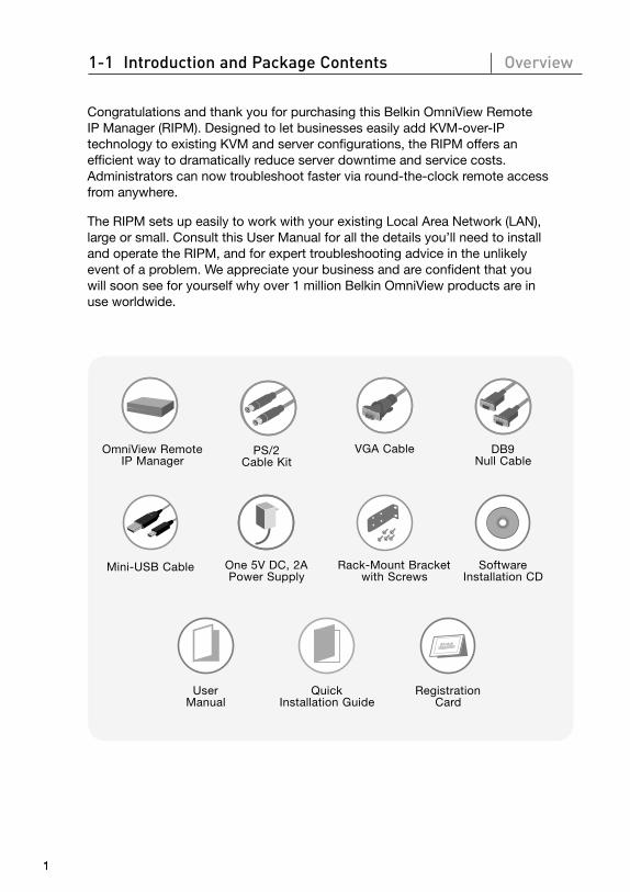
Congratulations and thank you for purchasing this Belkin OmniView Remote IP Manager (RIPM). Designed to let businesses easily add KVM-over-IP technology to existing KVM and server configurations, the RIPM offers an efficient way to dramatically reduce server downtime and service costs. Administrators can now troubleshoot faster via round-the-clock remote access from anywhere.
The RIPM sets up easily to work with your existing Local Area Network (LAN), large or small. Consult this User Manual for all the details you’ll need to install and operate the RIPM, and for expert troubleshooting advice in the unlikely event of a problem. We appreciate your business and are confident that you will soon see for yourself why over 1 million Belkin OmniView products are in use worldwide.
1
2
3
4
5
6
section
2
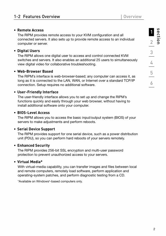
1-2 Features Overview Overview
• Remote AccessThe RIPM provides remote access to your KVM configuration and all connected servers. It also sets up to provide remote access to an individual computer or server.
• Digital UsersThe RIPM allows one digital user to access and control connected KVM switches and servers. It also enables an additional 25 users to simultaneously view digital video for collaborative troubleshooting.
• Web-Browser BasedThe RIPM’s interface is web-browser-based; any computer can access it, as long as it is connected to the LAN, WAN, or Internet over a standard TCP/IP connection. Setup requires no additional software.
• User-Friendly InterfaceThe user-friendly interface allows you to set up and change the RIPM’s functions quickly and easily through your web browser, without having to install additional software onto your computer.
• BIOS-Level AccessThe RIPM allows you to access the basic input/output system (BIOS) of your servers to make adjustments and perform reboots.
• Serial Device SupportThe RIPM provides support for one serial device, such as a power distribution unit (PDU), so you can perform hard reboots of your servers remotely.
• Enhanced SecurityThe RIPM provides 256-bit SSL encryption and multi-user password protection to prevent unauthorized access to your servers.
• Virtual Media* With virtual-media capability, you can transfer images and files between local and remote computers, remotely load software, perform application and operating-system patches, and perform diagnostic testing from a CD.
*Available on Windows®-based computers only.
3
• Account ManagementThe RIPM allows the administrator to create multiple user accounts and control access to servers.
• Event LogThe Event Log captures and stores all user activity on the RIPM.
• Email NotificationThe RIPM enables the administrator to monitor user activity and sends email notification of logins, invalid logins, and logouts.
• Multiple Platform SupportThe RIPM works with KVM switches or servers with PS/2 or USB console connections.
• Video ResolutionWith a 117MHz bandwidth, the RIPM is able to support video resolutions of up to 1600x1200@75Hz.
• 0U Rack-MountableThe RIPM is compact enough to be positioned on your desktop or mounted on the back of your server rack for 0U installation.
• Firmware UpdatesFlash upgrades allow you to obtain the latest firmware updates for your RIPM. These firmware updates ensure that the RIPM is compatible with the latest devices and hardware and are free for the life of the RIPM. Visit www.belkin.com for upgrade information and support.
1-2 Features Overview Overview
1
2
3
4
5
6
section
444
1-3 Equipment Requirements Overview
Hardware Requirements• OmniView Series Remote IP Manager (included)
• PS/2 Cable Kit (included)
• VGA Cable (included)
• Mini-USB Cable (included)
• 5V DC, 2A Power Supply (included)
• Keyboard, monitor, and mouse
• Connection to network using 10/100Base-T Ethernet port (RJ45)
• CAT5 cable
• Rack-mount bracket with screws (included in box for rack-mount-install option)
5
1-4 Systems Supported Overview
Windows 2000, 2003, XP; Red Hat® Linux® 7.x and above; UNIX®; Mac OS® X v10.0 and above (requires KVM); Sun™ Solaris™ 8.x and above (with Sun adapter—Belkin part# F1DE083)
Browsers Supported• Microsoft® Internet Explorer 6.0 and above
• Netscape® Navigator® 7.0

1
2
3
4
5
6
section
6
1-5 Specifications Overview
Part Number: F1DE101H
Power: 5V DC, 2A
No. of Users Supported: 1 local, 1 digital (1 simultaneous user)
Keyboard Emulation: PS/2 and USB
Mouse Emulation: PS/2 and USB
Monitors Supported: CRT and LCD (with VGA support)
Resolution Support: Up to 1600x1200@75Hz
Maximum Remote Bandwidth: 5MB
Keyboard Input: MiniDIN6 (PS/2)
Mouse Input: MiniDIN6 (PS/2)
Monitor Port: HDDB15 female (VGA)
CPU USB Port: Mini USB
Network Connection: RJ45
Encryption Modes: 256-bit SSL, 128-bit, AES, DES, 3DES
Authentication Support: LDAP (via local LDAP client), RADIUS, AD
Protocol Support: SNMP v1, IPv4
Serial Device Port: DB9
LED Indicators: 2
Enclosure: Metal
Dimensions: 6.75 (W) x 1.75 (H) x 4.5 (L) in. (171 x 44 x 114mm)
Weight: 1.65 lbs. (0.75kg.)
Operating Temp: 32° F to 120° F (0° C to 48.89° C)
Storage Temp: -4° F to 140° F (-20° C to 60° C)
Humidity: 5% to 80%
Warranty: 2 years
Note: Specifications are subject to change without notice.
7
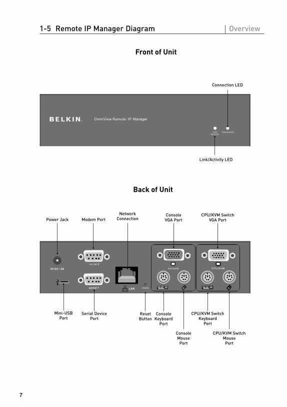
1-5 Remote IP Manager Diagram Overview
7
Link/Activity LED
Connection LED
Front of Unit
Back of Unit
Power Jack Modem PortNetwork
ConnectionConsole VGA Port
CPU/KVM Switch VGA Port
Serial Device Port
Mini-USB Port
CPU/KVM Switch Keyboard
Port
CPU/KVM Switch Mouse
Port
Console Mouse
Port
Console Keyboard
Port
Reset Button
1
2
3
4
5
6
section
8
2-1 Hardware Installation Installation
8
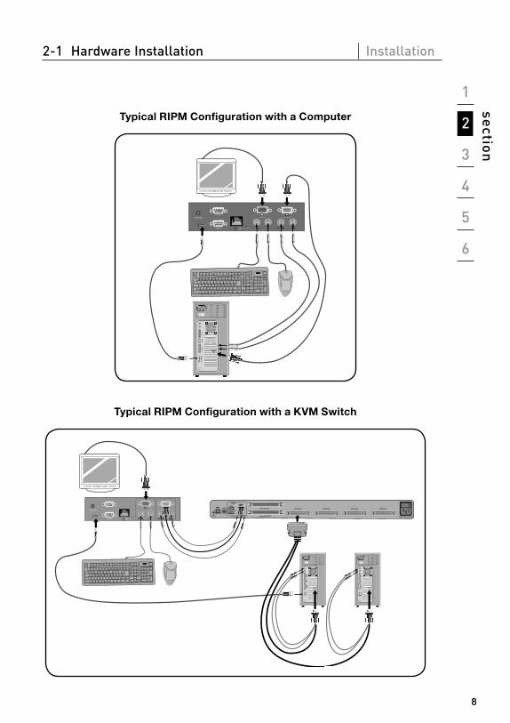
Typical RIPM Configuration with a Computer
Typical RIPM Configuration with a KVM Switch
�������
��������
����������
���������
���������������
�������������� ��������� ��������� ��������� ���������
��������������������
������������

9
2-1 Hardware Installation Installation
Step 1 Installing the RIPM into a Server Rack
The RIPM includes mounting brackets for installation in 19-inch racks.
1.1 Attach the included bracket to the top or bottom of the RIPM with the provided screws.
Fig. 1
1.2 Mount the RIPM to the rack. See Fig. 1.
Note: Mounting screws for the rack are not included. Please use the specified screws from your rack’s manufacturer.
Warning: Before attempting to connect anything to the RIPM or your computer(s), please ensure that all your computer equipment and devices are powered off. Belkin Corporation is not responsible for damage caused by your failure to do so.
Step 2 Connecting your Console to the RIPM
Fig. 2
2.1 Connect your keyboard and mouse to the “Console” keyboard and mouse ports on the RIPM.
2.2 Connect your monitor to the “Console” VGA port on the RIPM. See Fig. 2.
1
2
3
4
5
6
section
10
2-1 Hardware Installation Installation
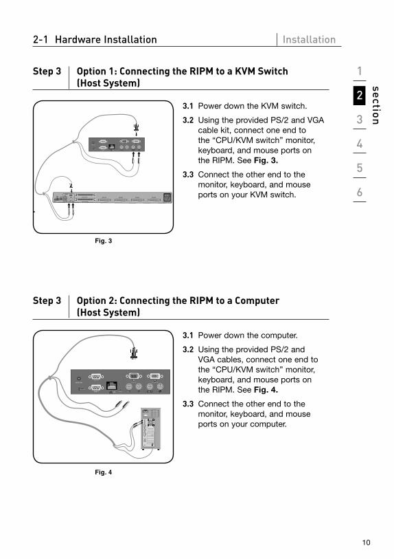
Step 3 Option 1: Connecting the RIPM to a KVM Switch (Host System)
�������
��������
����������
���������
���������������
�������������� ��������� ��������� ��������� ���������
��������������������
������������
Fig. 3
3.1 Power down the KVM switch.
3.2 Using the provided PS/2 and VGA cable kit, connect one end to the “CPU/KVM switch” monitor, keyboard, and mouse ports on the RIPM. See Fig. 3.
3.3 Connect the other end to the monitor, keyboard, and mouse ports on your KVM switch.
.
Step 3 Option 2: Connecting the RIPM to a Computer (Host System)
Fig. 4
3.1 Power down the computer.
3.2 Using the provided PS/2 and VGA cables, connect one end to the “CPU/KVM switch” monitor, keyboard, and mouse ports on the RIPM. See Fig. 4.
3.3 Connect the other end to the monitor, keyboard, and mouse ports on your computer.
11
2-1 Hardware Installation Installation
11
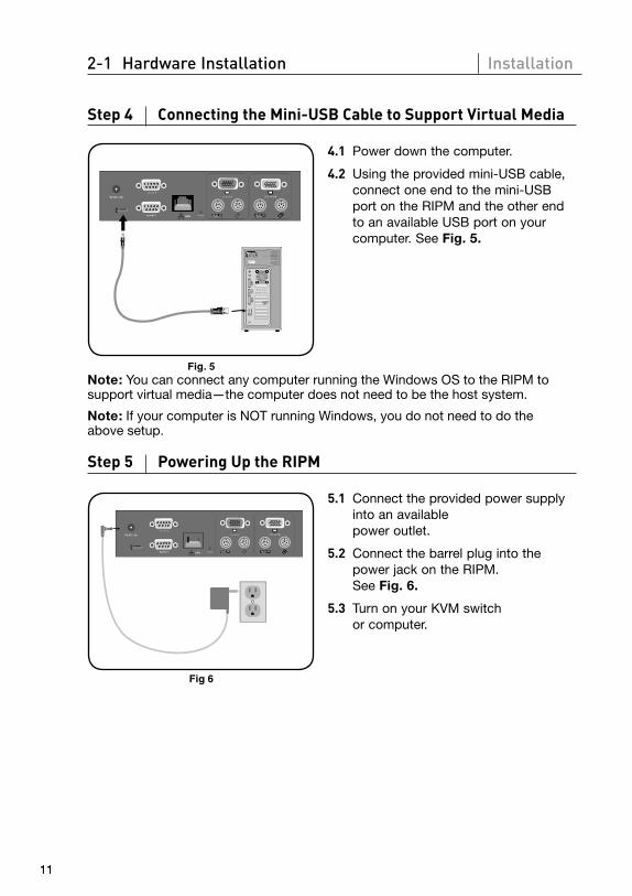
Step 4 Connecting the Mini-USB Cable to Support Virtual Media
4.1 Power down the computer.
Fig. 5
4.2 Using the provided mini-USB cable, connect one end to the mini-USB port on the RIPM and the other end to an available USB port on your computer. See Fig. 5.
Note: You can connect any computer running the Windows OS to the RIPM to support virtual media—the computer does not need to be the host system.
Note: If your computer is NOT running Windows, you do not need to do the above setup.
Step 5 Powering Up the RIPM
Fig 6
5.1 Connect the provided power supply into an available power outlet.
5.2 Connect the barrel plug into the power jack on the RIPM. See Fig. 6.
5.3 Turn on your KVM switch or computer.
1
2
3
4
5
6
section
12
2-2 Device Setup Installation
12
There are two ways to set up and configure the RIPM. You can use the device-setup software provided on the CD enclosed in the box, or you can connect a serial interface cable to the RIPM and use terminal software (e.g., HyperTerminal®).
Note: Belkin recommends using the device-setup software provided.
13
2-3 Software Installation Installation
13
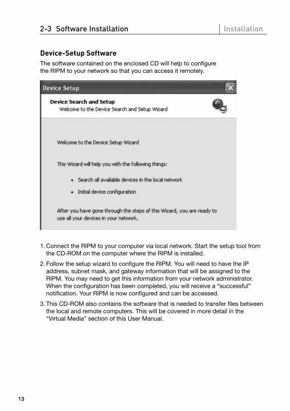
Device-Setup SoftwareThe software contained on the enclosed CD will help to configure the RIPM to your network so that you can access it remotely.
1. Connect the RIPM to your computer via local network. Start the setup tool from the CD-ROM on the computer where the RIPM is installed.
2. Follow the setup wizard to configure the RIPM. You will need to have the IP address, subnet mask, and gateway information that will be assigned to the RIPM. You may need to get this information from your network administrator. When the configuration has been completed, you will receive a “successful” notification. Your RIPM is now configured and can be accessed.
3. This CD-ROM also contains the software that is needed to transfer files between the local and remote computers. This will be covered in more detail in the “Virtual Media” section of this User Manual.

1
2
3
4
5
6
section
14
2-4 Configuration via Serial Interface Installation
To configure the RIPM via serial interface, a null modem cable is required (provided). Connect the null modem cable to the “Serial 01” port on the RIPM and the other end to the serial port on the computer. The serial interface needs to be adjusted with the parameters as shown below:
Parameter Value
Bits/second 115200
Data bits 8
Parity no
Stop bits 1
Flow control none
Use a terminal software program (e.g., HyperTerminal) to connect to the RIPM. Reset the RIPM and immediately press the “ESC” key. You will see a “=>” prompt. Enter the command “config” and press the “ENTER” key. You will be asked to adjust the IP auto configuration, the IP address, the net mask, and the default gateway. Pressing the “ENTER” key without entering values does not change settings. The gateway value has to be set to “0.0.0.0” (for no gateway) or any other value for the IP address of the gateway. After the confirmation, the RIPM performs a reset using the new values as set before.
15
2-5 Using your Remote IP Manager Installation
Web InterfaceThe RIPM may be accessed using a standard Java™-enabled web browser. You may use the HTTP protocol or a secure encrypted connection via HTTPS. Just enter the configured IP address of the RIPM into your web browser. The initial login settings are:
Parameter Value
Login administrator
Password belkin
Changing these settings to user-specific values is strongly recommended and can be done on the “User Management” page.
Telnet A standard Telnet client can be used to access an arbitrary device connected to the RIPM serial port via a terminal mode.
The primary interface of the RIPM is the HTTP interface. In order to use the Remote Console window of your managed host system, the browser has to come with a Java Runtime Environment version 1.1 or higher. If the browser has no Java support (such as on a small handheld device), you are still able to maintain your remote host system using the administration forms displayed by the browser itself.
For an unsecured connection to the RIPM, we can recommend the following web browsers:
• Microsoft Internet Explorer version 5.0 or higher on Windows 2000 and XP
• Netscape Navigator 7.0 on Windows 2000 and XP
In order to access the remote host system using a securely encrypted connection, you need a browser that supports the HTTPS protocol. Strong security is only ensured by using a 128-bit key length.
1
2
3
4
5
6
section
16
3-1 Login to the Remote IP Manager The Remote Console
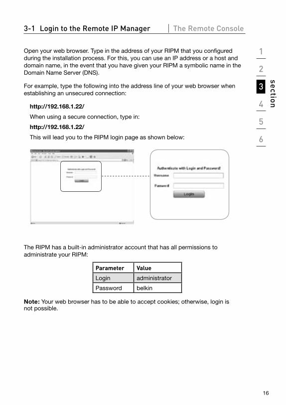
Open your web browser. Type in the address of your RIPM that you configured during the installation process. For this, you can use an IP address or a host and domain name, in the event that you have given your RIPM a symbolic name in the Domain Name Server (DNS).
For example, type the following into the address line of your web browser when establishing an unsecured connection:
http://192.168.1.22/
When using a secure connection, type in:
http://192.168.1.22/
This will lead you to the RIPM login page as shown below:
The RIPM has a built-in administrator account that has all permissions to administrate your RIPM:
Parameter Value
Login administrator
Password belkin
Note: Your web browser has to be able to accept cookies; otherwise, login is not possible.
17
3-2 Remote IP Manager Interface The Remote Console
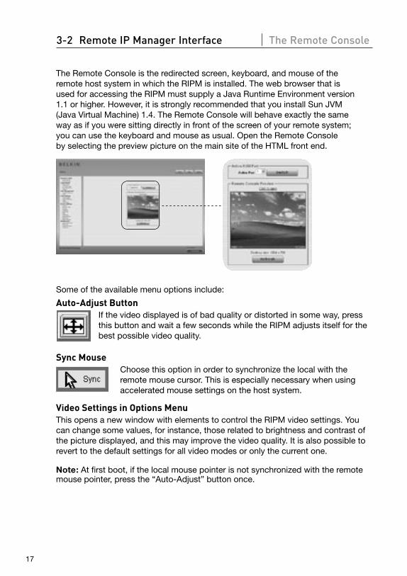
The Remote Console is the redirected screen, keyboard, and mouse of the remote host system in which the RIPM is installed. The web browser that is used for accessing the RIPM must supply a Java Runtime Environment version 1.1 or higher. However, it is strongly recommended that you install Sun JVM (Java Virtual Machine) 1.4. The Remote Console will behave exactly the same way as if you were sitting directly in front of the screen of your remote system; you can use the keyboard and mouse as usual. Open the Remote Console by selecting the preview picture on the main site of the HTML front end.
Some of the available menu options include:
Auto-Adjust Button If the video displayed is of bad quality or distorted in some way, press this button and wait a few seconds while the RIPM adjusts itself for the best possible video quality.
Sync MouseChoose this option in order to synchronize the local with the remote mouse cursor. This is especially necessary when using accelerated mouse settings on the host system.
Video Settings in Options Menu This opens a new window with elements to control the RIPM video settings. You can change some values, for instance, those related to brightness and contrast of the picture displayed, and this may improve the video quality. It is also possible to revert to the default settings for all video modes or only the current one.
Note: At first boot, if the local mouse pointer is not synchronized with the remote mouse pointer, press the “Auto-Adjust” button once.
1
2
3
4
5
6
section
18
3-3 Mouse, Keyboard, and Video Configuration The Remote Console
Between the RIPM and the host, there are two interfaces available for transmitting keyboard and mouse data: USB and PS/2 (available separately). The correct operation of the remote mouse depends on several settings, which will be discussed in the following subsections.
Remote IP Manager USB Interface To use the USB interface, you need to use correct cabling between the managed host and the managing device. For example, if the managed host has no USB keyboard support in the BIOS and you have connected the USB cable only, then you will have no remote-keyboard access during the boot process of the host. Please see the “Keyboard/Mouse” section on page 48.
Remote IP Manager Keyboard SettingsThe RIPM settings for the host’s keyboard type must be correct in order to make the remote keyboard work properly. Check the settings in the RIPM front end. See the “Keyboard/Mouse” section on page 48.
Remote-Mouse Settings A common problem with KVM devices is the synchronization between the local- and remote-mouse cursors. The RIPM addresses this situation with an intelligent synchronization algorithm. There are three mouse modes available on the RIPM.
• Auto-Mouse Speed The automatic-mouse-speed mode tries to detect the speed and acceleration
settings of the host system automatically. See the section below for a more detailed explanation.
• Fixed-Mouse Speed This mode translates the mouse movements from the
Remote Console in such a way that one pixel move will lead to pixel moves on the remote system. This parameter
is adjustable with the scaling. It should be noted that this works only when mouse acceleration is turned off on the remote system.
• Single-/Double-Mouse Modes This mode is described in the “Single- and Double-Mouse Modes” section on
page 20.
19
3-3 Mouse, Keyboard, and Video Configuration The Remote Console
Auto-Mouse-Speed and Mouse Synchronization The automatic-mouse-speed mode performs the speed detection during mouse synchronization. Whenever the mouse does not move correctly, there are two ways for re-synchronizing the local and remote mouse:
• Fast Sync The fast sync is used to correct a temporary but fixed skew. Choose this option
from the Remote Console Options menu. If defined, you may also press the mouse-synchronization hot-key sequence (see the “Remote Console Control Bar” section on page 23).
• Intelligent Sync If the fast sync does not work or the mouse settings have been changed on
the host system, use the intelligent sync instead. This method adjusts the parameters for the actual movement of the mouse pointer so that the mouse pointer is displayed at the correct position on the screen. This method takes more time than the fast sync and can be accessed with the appropriate item in the Remote Console Options menu. The intelligent sync requires a correctly adjusted picture. Use the auto-adjustment function or the manual correction in the Video Settings panel to set up the picture. The shape of the mouse pointer has a significant influence on the pointer detection. Belkin recommends that you use a simple, but common, pointer shape. In most cases, the detection and synchronization of animated pointer shapes is likely to fail. In general, pointer shapes that change during the pointer-detection process are almost impossible to figure out in the transferred video picture. Using a standard mouse-pointer shape ensures that the detection process is rather simple, and that the synchronization is at its best.
The “Mouse” button on top of the Remote Console can behave differently, depending on the current state of mouse synchronization. Usually, pressing this button leads to a fast sync, except in situations where the video mode has recently changed. See also the “Remote Console Control Bar” section on page 23.
Note: At first startup, if the local-mouse pointer is not synchronized with the remote-mouse pointer, press the “Auto-Adjust” button once.
1
2
3
4
5
6
section
20
3-3 Mouse, Keyboard, and Video Configuration The Remote Console
Host System Mouse SettingsThe host’s operating system knows various settings for the mouse driver.
While the RIPM works with accelerated mice and is able to synchronize the local- with the remote-mouse pointer, the following limitations may prevent this synchronization from working properly:
• Special Mouse Driver There are mouse drivers that influence the synchronization process and lead
to de-synchronized mouse pointers. If this happens, make sure you do not use a special vendor-specific mouse driver on your host system.
• Windows 2003 Server/XP Mouse Settings Windows XP has a setting named “improve mouse acceleration” that must
be deactivated.
• Active Desktop If the “Active Desktop” feature of Microsoft Windows is enabled, do not use a
plain background. Instead, use some kind of wallpaper. As an alternative, you could also disable the Active Desktop completely.
Navigate your mouse pointer into the upper-left corner of the applet screen and move it slightly back and forth. This will re-synchronize the mouse. If re-synchronizing fails, disable the mouse acceleration and repeat the procedure.
• Single- and Double-Mouse Modes The information above applies to the double-mouse mode where
remote- and local-mouse pointers are visible and need to be synchronized. The RIPM features another mode, the single-mouse mode, where only the remote-mouse pointer is visible. Activate this mode in the Remote Console (see the “Remote Console Control Bar” section on page 23) and click into the window area. The local-mouse pointer will be hidden, and the remote one can be controlled directly. To leave this mode, it is necessary to define a mouse hot key in the Remote Console Settings panel. Press this key to free the captured local-mouse pointer.
21
3-3 Mouse, Keyboard, and Video Configuration The Remote Console
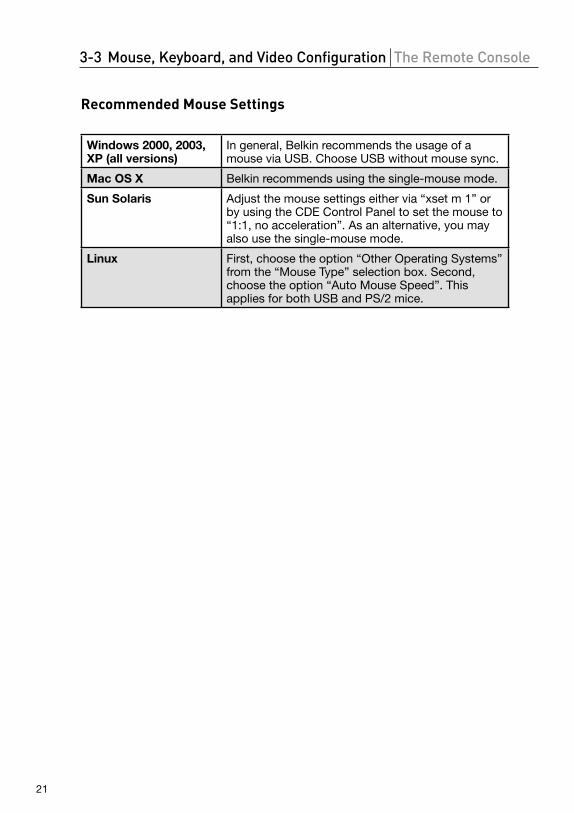
Recommended Mouse Settings
Windows 2000, 2003, XP (all versions)
In general, Belkin recommends the usage of a mouse via USB. Choose USB without mouse sync.
Mac OS X Belkin recommends using the single-mouse mode.
Sun Solaris Adjust the mouse settings either via “xset m 1” or by using the CDE Control Panel to set the mouse to “1:1, no acceleration”. As an alternative, you may also use the single-mouse mode.
Linux First, choose the option “Other Operating Systems” from the “Mouse Type” selection box. Second, choose the option “Auto Mouse Speed”. This applies for both USB and PS/2 mice.
1
2
3
4
5
6
section
22
3-3 Mouse, Keyboard, and Video Configuration The Remote Console
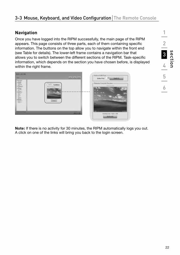
Navigation Once you have logged into the RIPM successfully, the main page of the RIPM appears. This page consists of three parts, each of them containing specific information. The buttons on the top allow you to navigate within the front end (see Table for details). The lower-left frame contains a navigation bar that allows you to switch between the different sections of the RIPM. Task-specific information, which depends on the section you have chosen before, is displayed within the right frame.
Note: If there is no activity for 30 minutes, the RIPM automatically logs you out. A click on one of the links will bring you back to the login screen.
23
3-4 Remote Console Control Bar The Remote Console
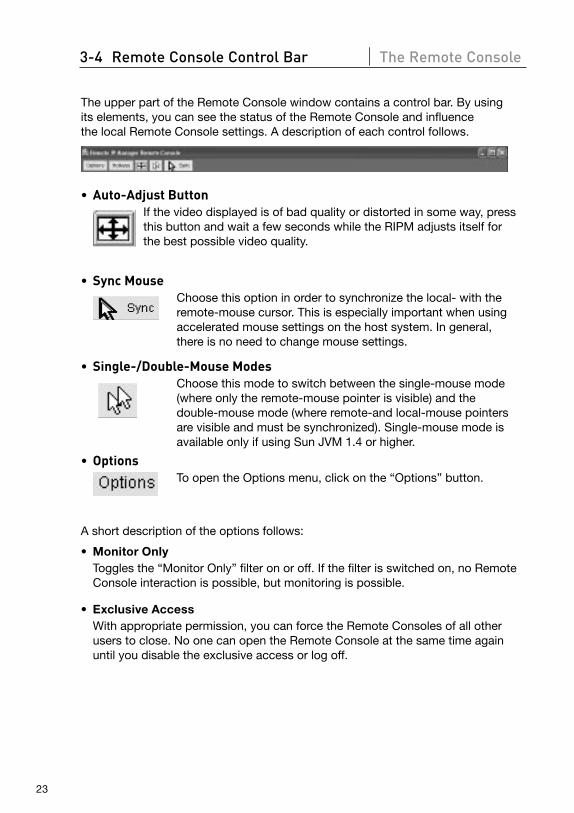
The upper part of the Remote Console window contains a control bar. By using its elements, you can see the status of the Remote Console and influence the local Remote Console settings. A description of each control follows.
• Auto-Adjust Button If the video displayed is of bad quality or distorted in some way, press
this button and wait a few seconds while the RIPM adjusts itself for the best possible video quality.
• Sync Mouse Choose this option in order to synchronize the local- with the
remote-mouse cursor. This is especially important when using accelerated mouse settings on the host system. In general, there is no need to change mouse settings.
• Single-/Double-Mouse Modes Choose this mode to switch between the single-mouse mode
(where only the remote-mouse pointer is visible) and the double-mouse mode (where remote-and local-mouse pointers are visible and must be synchronized). Single-mouse mode is available only if using Sun JVM 1.4 or higher.
• Options To open the Options menu, click on the “Options” button.
A short description of the options follows:
• Monitor Only Toggles the “Monitor Only” filter on or off. If the filter is switched on, no Remote
Console interaction is possible, but monitoring is possible.
• Exclusive Access With appropriate permission, you can force the Remote Consoles of all other
users to close. No one can open the Remote Console at the same time again until you disable the exclusive access or log off.
1
2
3
4
5
6
section
24
3-4 Remote Console Control Bar The Remote Console
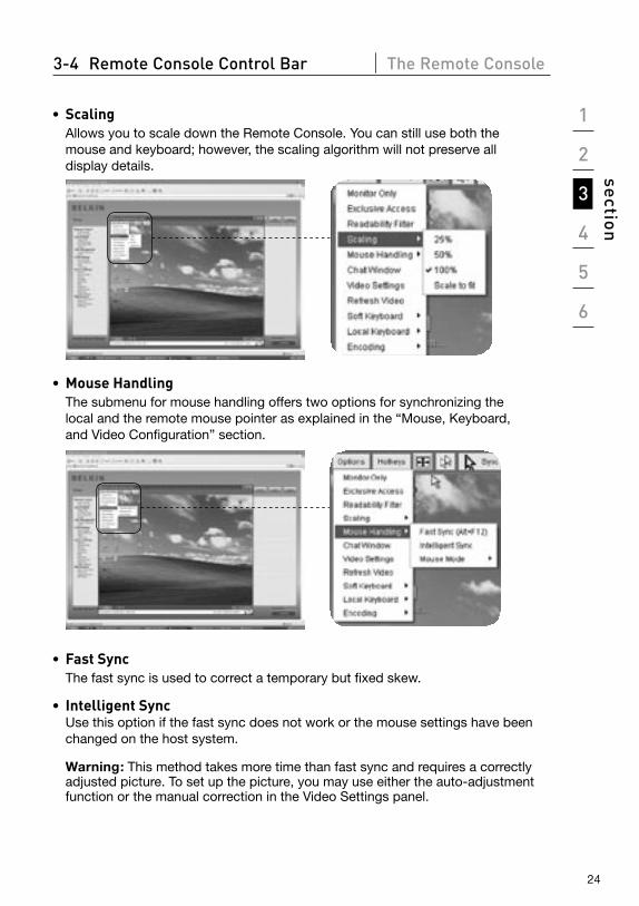
• Scaling Allows you to scale down the Remote Console. You can still use both the
mouse and keyboard; however, the scaling algorithm will not preserve all display details.
• Mouse Handling The submenu for mouse handling offers two options for synchronizing the
local and the remote mouse pointer as explained in the “Mouse, Keyboard, and Video Configuration” section.
• Fast Sync The fast sync is used to correct a temporary but fixed skew.
• Intelligent Sync Use this option if the fast sync does not work or the mouse settings have been changed on the host system.
Warning: This method takes more time than fast sync and requires a correctly adjusted picture. To set up the picture, you may use either the auto-adjustment function or the manual correction in the Video Settings panel.
25
3-4 Remote Console Control Bar The Remote Console
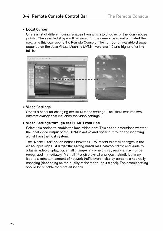
• Local Cursor Offers a list of different cursor shapes from which to choose for the local-mouse
pointer. The selected shape will be saved for the current user and activated the next time this user opens the Remote Console. The number of available shapes depends on the Java Virtual Machine (JVM)—versions 1.2 and higher offer the full list.
• Video Settings Opens a panel for changing the RIPM video settings. The RIPM features two
different dialogs that influence the video settings.
• Video Settings through the HTML Front End Select this option to enable the local video port. This option determines whether
the local video output of the RIPM is active and passing through the incoming signal from the host system.
The “Noise Filter” option defines how the RIPM reacts to small changes in the video-input signal. A large filter setting needs less network traffic and leads to a faster video display, but small changes in some display regions may not be recognized immediately. A small filter displays all changes instantly but may lead to a constant amount of network traffic even if display content is not really changing (depending on the quality of the video-input signal). The default setting should be suitable for most situations.
1
2
3
4
5
6
section
26
3-4 Remote Console Control Bar The Remote Console
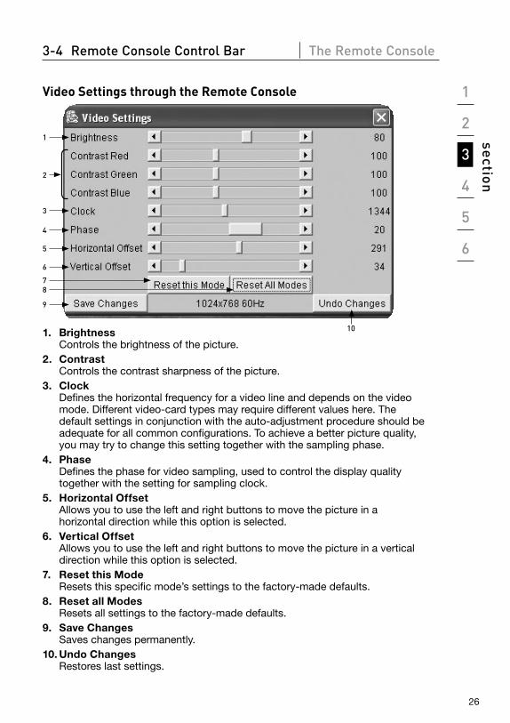
Video Settings through the Remote Console
1
2
3
6
5
9
4
7
10
8
1. Brightness Controls the brightness of the picture.2. Contrast Controls the contrast sharpness of the picture.3. Clock
Defines the horizontal frequency for a video line and depends on the video mode. Different video-card types may require different values here. The default settings in conjunction with the auto-adjustment procedure should be adequate for all common configurations. To achieve a better picture quality, you may try to change this setting together with the sampling phase.
4. Phase Defines the phase for video sampling, used to control the display quality together with the setting for sampling clock.
5. Horizontal Offset Allows you to use the left and right buttons to move the picture in a horizontal direction while this option is selected.
6. Vertical Offset Allows you to use the left and right buttons to move the picture in a vertical direction while this option is selected.
7. Reset this Mode Resets this specific mode’s settings to the factory-made defaults.
8. Reset all Modes Resets all settings to the factory-made defaults.
9. Save Changes Saves changes permanently.
10. Undo Changes Restores last settings.
27
3-4 Remote Console Control Bar The Remote Console
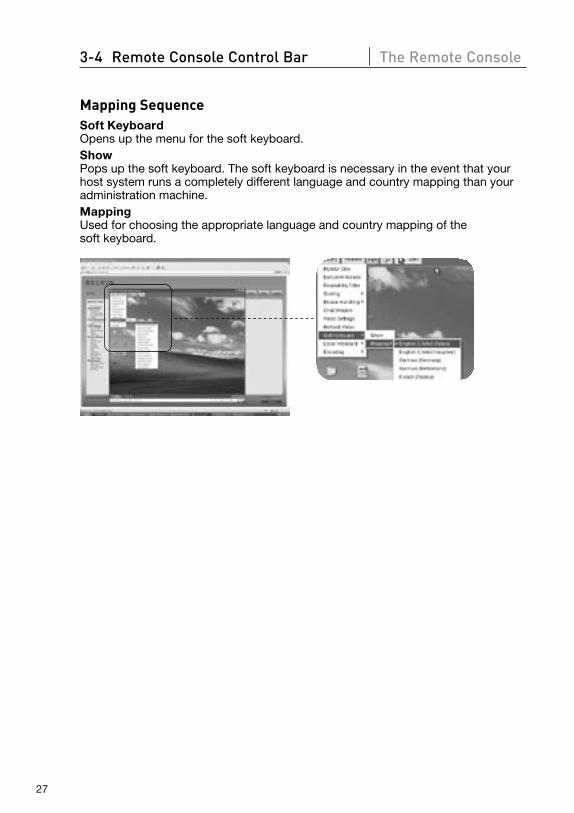
Mapping SequenceSoft Keyboard Opens up the menu for the soft keyboard.Show Pops up the soft keyboard. The soft keyboard is necessary in the event that your host system runs a completely different language and country mapping than your administration machine.Mapping Used for choosing the appropriate language and country mapping of the soft keyboard.
1
2
3
4
5
6
section
28
3-4 Remote Console Control Bar The Remote Console
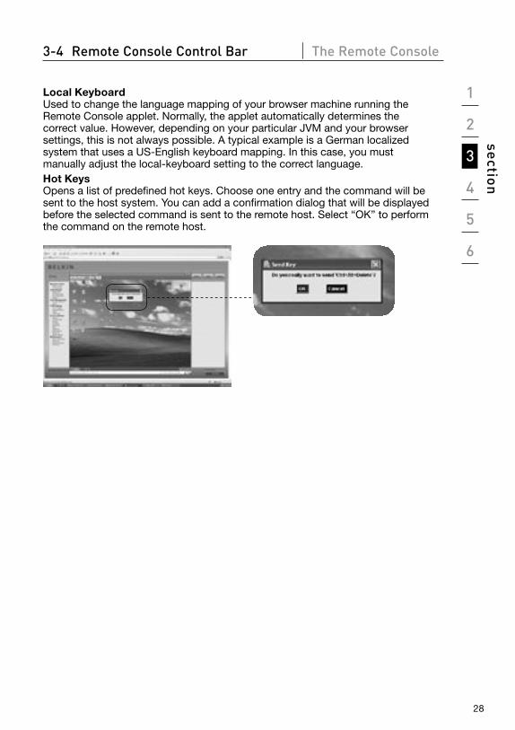
Local Keyboard Used to change the language mapping of your browser machine running the Remote Console applet. Normally, the applet automatically determines the correct value. However, depending on your particular JVM and your browser settings, this is not always possible. A typical example is a German localized system that uses a US-English keyboard mapping. In this case, you must manually adjust the local-keyboard setting to the correct language.Hot Keys Opens a list of predefined hot keys. Choose one entry and the command will be sent to the host system. You can add a confirmation dialog that will be displayed before the selected command is sent to the remote host. Select “OK” to perform the command on the remote host.
29
3-4 Remote Console Control Bar The Remote Console
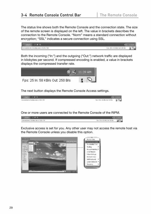
The status line shows both the Remote Console and the connection state. The size of the remote screen is displayed on the left. The value in brackets describes the connection to the Remote Console. “Norm” means a standard connection without encryption; “SSL” indicates a secure connection using SSL.
Both the incoming (“In:”) and the outgoing (“Out:”) network traffic are displayed in kilobytes per second. If compressed encoding is enabled, a value in brackets displays the compressed transfer rate.
The next button displays the Remote Console Access settings.
One or more users are connected to the Remote Console of the RIPM.
Exclusive access is set for you. Any other user may not access the remote host via the Remote Console unless you disable this option.

1
2
3
4
5
6
section
30
3-4 Remote Console Control Bar The Remote Console
A remote user has exclusive access. You may not access the remote host via the Remote Console unless the other user disables this option.
The outer-right button displays the state of the “Monitor Only” settings.
The “Monitor Only” option disabled.
The “Monitor Only” option is enabled.
For more information about Monitor Only and Exclusive Access settings, see the “Remote Console Control Bar” section on page 23 of this User Manual.
31
3-5 Remote Console Status Line The Remote Console
Resetting the Remote IP Manager to Factory SettingsTo reset the RIPM and change the network settings back to the factory defaults:
1. Make a serial connection for initial configuration (HyperTerminal)
Bits per second: 115200
Data bits: 8
Parity: none
Stop bits: 1
Flow control: hardware or none
2. Press the reset button, located between the power DC jack and the network jack. Release the reset button and immediately press the ESC key in the serial terminal program (HyperTerminal) several times until the prompt “=>” appears.
Note: If the prompt does not come up within the first three seconds after releasing the reset button, repeat Steps 1 and 2. The RIPM will detect the ESC key only during the first three seconds of the boot process.
3. When prompted, type “defaults” and press the enter key. The RIPM will then boot and reset back to the factory settings.
4. Power down your server (the computer to which the RIPM is locally connected).
5. Unplug the power supply from the RIPM as well as the “CPU/KVM switch” port cables and the network cable.
6. Reconnect the cables and power up your server.
Now you can reconfigure the RIPM to your network settings through a HyperTerminal connection, or by using the setup software.
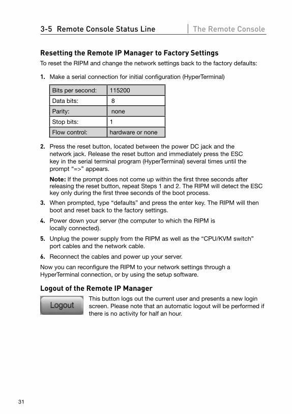
Logout of the Remote IP Manager This button logs out the current user and presents a new login
screen. Please note that an automatic logout will be performed if there is no activity for half an hour.
1
2
3
4
5
6
section
32
4-1 Remote Control Menu Options
KVM Console
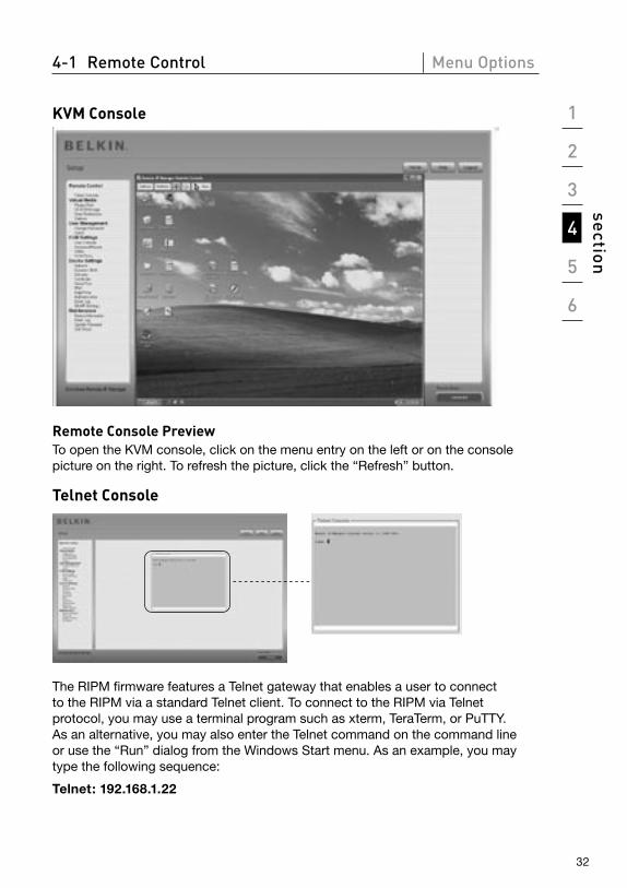
Remote Console Preview To open the KVM console, click on the menu entry on the left or on the console picture on the right. To refresh the picture, click the “Refresh” button.
Telnet Console
The RIPM firmware features a Telnet gateway that enables a user to connect to the RIPM via a standard Telnet client. To connect to the RIPM via Telnet protocol, you may use a terminal program such as xterm, TeraTerm, or PuTTY. As an alternative, you may also enter the Telnet command on the command line or use the “Run” dialog from the Windows Start menu. As an example, you may type the following sequence:
Telnet: 192.168.1.22
33
4-1 Remote Control Menu Options
Replace the IP address with the one that was assigned to the RIPM during installation. You will then be prompted for the username and password information in order to log in to the device. The credentials that need to be entered for authentication are identical to those of the web interface. That means the user management of the Telnet interface is entirely controlled with the appropriate functions of the web interface. Once you have successfully logged in to the RIPM, a command line will be presented and you can enter the appropriate management commands. In general, the Telnet interface supports two operation modes: the command-line mode and the terminal mode. The command-line mode is used to control or display some parameters. In terminal mode, the pass-through access to serial port 1 is activated (if the serial settings were made correctly). To access the RIPM via serial interface, a null modem cable is required. All inputs are redirected to the device on serial port 1, and its answers are displayed on the Telnet interface.
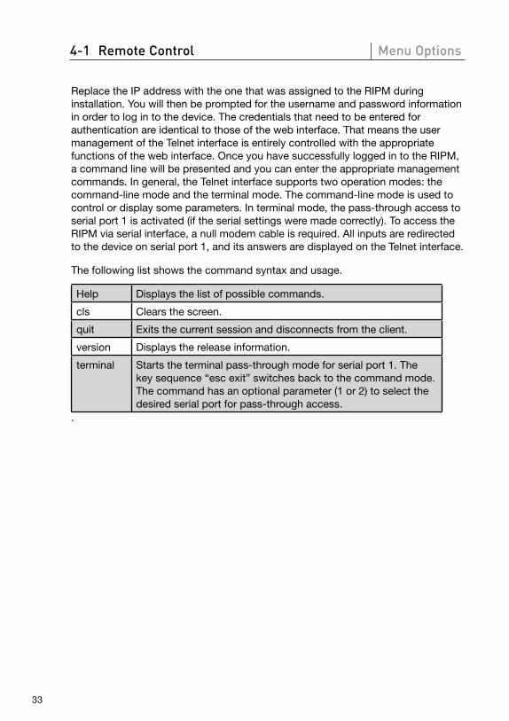
The following list shows the command syntax and usage.
Help Displays the list of possible commands.
cls Clears the screen.
quit Exits the current session and disconnects from the client.
version Displays the release information.
terminal Starts the terminal pass-through mode for serial port 1. The key sequence “esc exit” switches back to the command mode. The command has an optional parameter (1 or 2) to select the desired serial port for pass-through access.
.
1
2
3
4
5
6
section
34
4-2 Virtual Media Menu Options
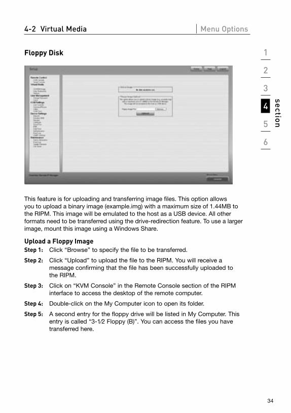
Floppy Disk
This feature is for uploading and transferring image files. This option allows you to upload a binary image (example.img) with a maximum size of 1.44MB to the RIPM. This image will be emulated to the host as a USB device. All other formats need to be transferred using the drive-redirection feature. To use a larger image, mount this image using a Windows Share.
Upload a Floppy Image Step 1: Click “Browse” to specify the file to be transferred.
Step 2: Click “Upload” to upload the file to the RIPM. You will receive a message confirming that the file has been successfully uploaded to the RIPM.
Step 3: Click on “KVM Console” in the Remote Console section of the RIPM interface to access the desktop of the remote computer.
Step 4: Double-click on the My Computer icon to open its folder.
Step 5: A second entry for the floppy drive will be listed in My Computer. This entry is called “3-1⁄2 Floppy (B)”. You can access the files you have transferred here.

35
4-2 Virtual Media Menu Options
CD-ROM ImageUse Image on Windows Share (SAMBA).
To include an image from a Windows Share, select “CD-ROM” from the submenu.
You must provide the following information in order to mount the selected image properly:
12345
1. Share Host The server name or its IP address. (This IP address is obtained by running the drive-redirection software—explained below.)
2. Share Name The name of the share folder to be used.
3. Path to Image The path of the image file on the share.
4. User (Optional) If necessary, specify the username for the share. If unspecified and a guest account is activated, this guest-account information will be used as your login.
5. Password (Optional) If requested to supply a password, specify the password for the given username.
1
2
3
4
5
6
section
36
4-2 Virtual Media Menu Options
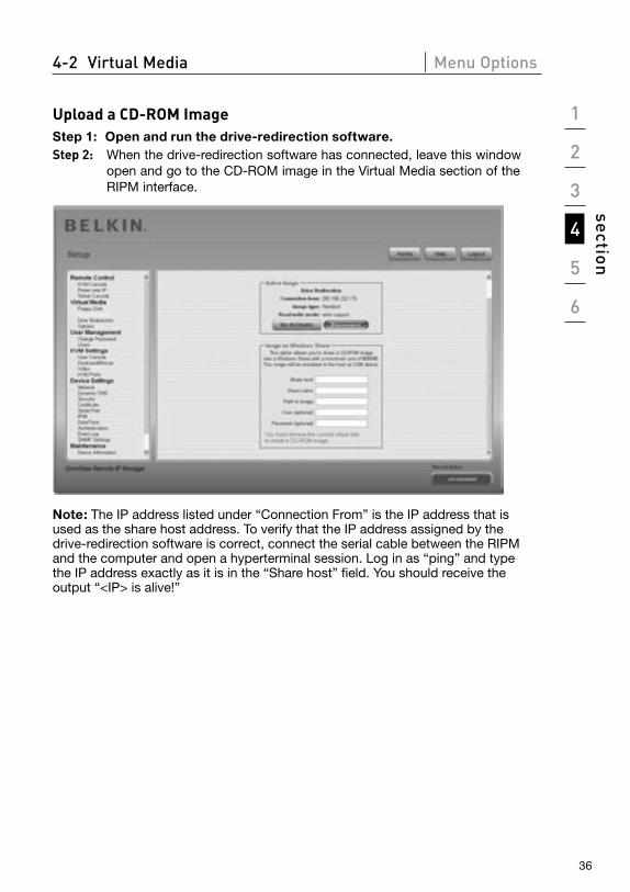
Upload a CD-ROM ImageStep 1: Open and run the drive-redirection software.Step 2: When the drive-redirection software has connected, leave this window
open and go to the CD-ROM image in the Virtual Media section of the RIPM interface.
Note: The IP address listed under “Connection From” is the IP address that is used as the share host address. To verify that the IP address assigned by the drive-redirection software is correct, connect the serial cable between the RIPM and the computer and open a hyperterminal session. Log in as “ping” and type the IP address exactly as it is in the “Share host” field. You should receive the output “<IP> is alive!”
37
4-2 Virtual Media Menu Options
Step 3: Click “Re-Activate” in the Active Image section.
Step 4: Enter the IP Address provided by the drive re-direction software into the “Share Host “ field.
Step 5: Enter the “Share name” and the “Path to Image.”
Step 6: To upload the file, click the “Set” button. The file will be displayed as a USB device on the remote computer.
The specified image file should be accessible from the RIPM. The information above must be given from the point of view of the RIPM. It is important to specify correct IP addresses and device names. Otherwise, the RIPM may not be able to access the referenced image file properly and will leave the given file un-mounted (displays an error message instead). Belkin recommends that you use the correct values and repeat this step, if necessary.
The specified share must be configured correctly. Therefore, administrative permissions are required. As an ordinary user, you may not have these permissions. You should either log in as a system administrator or ask your system administrator for help to complete this task.
1
2
3
4
5
6
section
38
4-2 Virtual Media Menu Options
Drive RedirectionThe drive-redirection feature provides another way to use a virtual disc drive on the remote computer. You can work with a drive on your local computer from the remote machine by sharing the drive over a TCP network connection. Storage devices including floppy and hard discs*, CD-ROMs, and removable media, such as USB sticks, can be redirected. You can even configure your remote machine to be able to write data to a local disc.
*Note: Belkin does not recommend enabling write support when redirecting hard disks and is not responsible for data lost or corrupted during this process.
Please exercise caution when using this feature. Drive redirection works on a level that is far below the operating system, so that neither the local nor the remote operating system can detect that a drive is being redirected at a given time. This can create inconsistent data when one of the operating systems (on either the local machine or the remote host) writes data to the device. With write support enabled, the remote computer can damage data and the file system on the redirected device. If, on the other hand, the local operating system writes data to the redirected device, the drive cache on the remote host’s operating system could contain older data, confusing the remote host’s operating system. We therefore recommend using drive redirection, especially the write-support function, with great care.
Note: To be able to use the drive-redirection feature, you must install the drive-redirection software, which was included with this product, on the computer you are using to access the RIPM remotely.
39
4-2 Virtual Media Menu Options
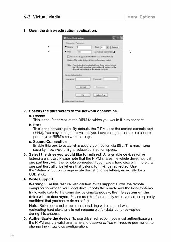
1. Open the drive-redirection application.
c
a
b
2. Specify the parameters of the network connection. a. Device
This is the IP address of the RIPM to which you would like to connect. b. Port
This is the network port. By default, the RIPM uses the remote console port (#443). You may change this value if you have changed the remote console port in your RIPM’s network settings.
c. Secure Connection Enable this box to establish a secure connection via SSL. This maximizes security; however, it might reduce connection speed.
3. Select the drive you would like to redirect. All available devices (drive letters) are shown. Please note that the RIPM shares the whole drive, not just one partition, with the remote computer. If you have a hard disc with more than one partition, all drive letters that belong to it will be redirected. Use the “Refresh” button to regenerate the list of drive letters, especially for a USB stick.
4. Write Support Warning: Use this feature with caution. Write support allows the remote
computer to write to your local drive. If both the remote and the local systems try to write data to the same device simultaneously, the file system on the drive will be destroyed. Please use this feature only when you are completely confident that you can to do so safely.
Note: Belkin does not recommend enabling write support when redirecting hard disks and is not responsible for data lost or corrupted during this process.
5. Authenticate the device. To use drive redirection, you must authenticate on the RIPM using a valid username and password. You will require permission to change the virtual disc configuration.
1
2
3
4
5
6
section
40
4-2 Virtual Media Menu Options
6. Establish drive redirection by pressing the “Connect” button once. If all the settings are correct, the status bar displays that the connection has been established, the “Connect” button is disabled, and the “Disconnect” button is enabled. In the event of an error, the status line shows the error message.
The drive-redirection software tries to lock the local drive before it is redirected. This prevents the local operating system from accessing the drive as long as it is redirected. The attempt will fail if a file on the drive is currently open. In the case of a locking failure, you will be prompted to confirm that you wish to establish the connection. However, remember that if write support is enabled, drive redirection could damage a drive that is not locked.
7. Use the “Disconnect” button to stop a drive redirection after the process has started.
8. Click “Exit” to shut down the drive-redirection program. If a drive-redirection connection is active, the connection will close before the application terminates.
9. Use the “Hide to Tray” button to minimize the application without terminating it completely. An active connection will remain until you close the application. You can access the software by double-clicking on its tray icon. The tray icon also indicates whether or not a connection is established. Right-click on it to access a submenu.
OptionsDisable Drive Redirection This switches off drive redirection.Force Read-Only Connections This switches off write support for drive redirection. Click “Apply” to submit your changes.
41
4-2 Virtual Media Menu Options
Creating an ImageFloppy Images UNIX® and UNIX-Like Operating Systems (OS)
To create an image file, make use of “dd”. This is one of the original UNIX utilities and is included in every UNIX-like OS (UNIX, Sun Solaris, Linux). To create a floppy image file, copy the contents of a floppy to a file. You can use the following command: dd [ if=/dev/fd0 ] [ of=/tmp/floppy.image ]. In this case, “dd” reads the entire disc from the device “/dev/fd0” and saves the output in the specified output file “/tmp/floppy.image”. Adjust both parameters exactly to your needs (input device, etc.).
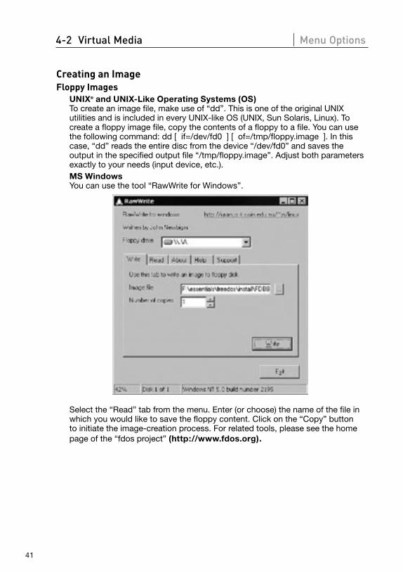
MS Windows You can use the tool “RawWrite for Windows”.
Select the “Read” tab from the menu. Enter (or choose) the name of the file in which you would like to save the floppy content. Click on the “Copy” button to initiate the image-creation process. For related tools, please see the home page of the “fdos project” (http://www.fdos.org).
1
2
3
4
5
6
section
42
4-2 Virtual Media Menu Options
CD-ROM/ISO 9660 Images UNIX and UNIX-Like OS
To create an image file, make use of “dd”. This is one of the original UNIX utilities and is included in every UNIX-like OS (UNIX, Sun Solaris, Linux). To create a CD-ROM image, copy the contents of the CD-ROM to a file. You can use the following command: dd [ if=/dev/cdrom ] [ of=/tmp/cdrom.image ]. In this case, “dd” reads the entire disc from the device “/dev/cdrom” and saves the output in the specified output file “/tmp/cdrom.image”. Adjust both parameters exactly to your needs (input device, etc.).
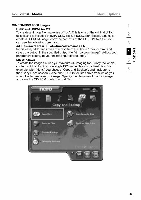
MS Windows To create the image file, use your favorite CD imaging tool. Copy the whole contents of the disc into one single ISO image file on your hard disk. For example, with “Nero,” you choose “Copy and Backup”, and navigate to the “Copy Disc” section. Select the CD-ROM or DVD drive from which you would like to create an ISO image. Specify the file name of the ISO image and save the CD-ROM content in that file.
43
4-3 User Management Menu Options
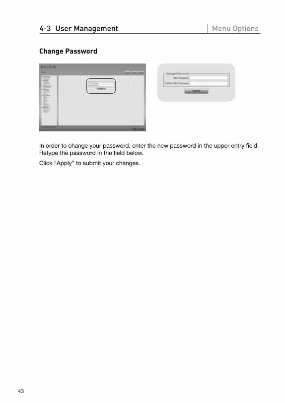
Change Password
In order to change your password, enter the new password in the upper entry field. Retype the password in the field below.
Click “Apply” to submit your changes.
1
2
3
4
5
6
section
44
4-3 User Management Menu Options
Users
12
34567
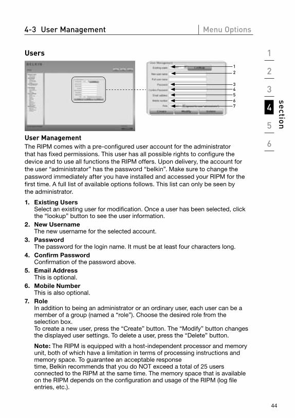
User Management The RIPM comes with a pre-configured user account for the administrator that has fixed permissions. This user has all possible rights to configure the device and to use all functions the RIPM offers. Upon delivery, the account for the user “administrator” has the password “belkin”. Make sure to change the password immediately after you have installed and accessed your RIPM for the first time. A full list of available options follows. This list can only be seen by the administrator.
1. Existing Users Select an existing user for modification. Once a user has been selected, click the “lookup” button to see the user information.
2. New Username The new username for the selected account.
3. Password The password for the login name. It must be at least four characters long.
4. Confirm Password Confirmation of the password above.
5. Email Address This is optional.
6. Mobile Number This is also optional.
7. Role In addition to being an administrator or an ordinary user, each user can be a member of a group (named a “role”). Choose the desired role from the selection box. To create a new user, press the “Create” button. The “Modify” button changes the displayed user settings. To delete a user, press the “Delete” button.
Note: The RIPM is equipped with a host-independent processor and memory unit, both of which have a limitation in terms of processing instructions and memory space. To guarantee an acceptable response time, Belkin recommends that you do NOT exceed a total of 25 users connected to the RIPM at the same time. The memory space that is available on the RIPM depends on the configuration and usage of the RIPM (log file entries, etc.).
45
4-4 KVM Settings Menu Options
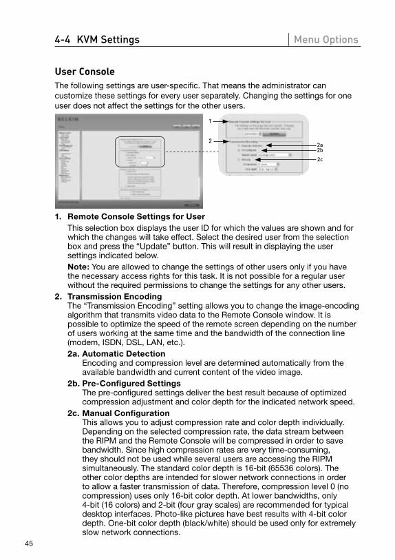
User ConsoleThe following settings are user-specific. That means the administrator can customize these settings for every user separately. Changing the settings for one user does not affect the settings for the other users.
1
22a2b
2c
1. Remote Console Settings for User This selection box displays the user ID for which the values are shown and for
which the changes will take effect. Select the desired user from the selection box and press the “Update” button. This will result in displaying the user settings indicated below.
Note: You are allowed to change the settings of other users only if you have the necessary access rights for this task. It is not possible for a regular user without the required permissions to change the settings for any other users.
2. Transmission Encoding The “Transmission Encoding” setting allows you to change the image-encoding
algorithm that transmits video data to the Remote Console window. It is possible to optimize the speed of the remote screen depending on the number of users working at the same time and the bandwidth of the connection line (modem, ISDN, DSL, LAN, etc.).
2a. Automatic Detection Encoding and compression level are determined automatically from the available bandwidth and current content of the video image.
2b. Pre-Configured Settings The pre-configured settings deliver the best result because of optimized compression adjustment and color depth for the indicated network speed.
2c. Manual Configuration This allows you to adjust compression rate and color depth individually.
Depending on the selected compression rate, the data stream between the RIPM and the Remote Console will be compressed in order to save bandwidth. Since high compression rates are very time-consuming, they should not be used while several users are accessing the RIPM simultaneously. The standard color depth is 16-bit (65536 colors). The other color depths are intended for slower network connections in order to allow a faster transmission of data. Therefore, compression level 0 (no compression) uses only 16-bit color depth. At lower bandwidths, only 4-bit (16 colors) and 2-bit (four gray scales) are recommended for typical desktop interfaces. Photo-like pictures have best results with 4-bit color depth. One-bit color depth (black/white) should be used only for extremely slow network connections.
1
2
3
4
5
6
section
46
4-4 KVM Settings Menu Options
44b
33b3a
4a
5
6
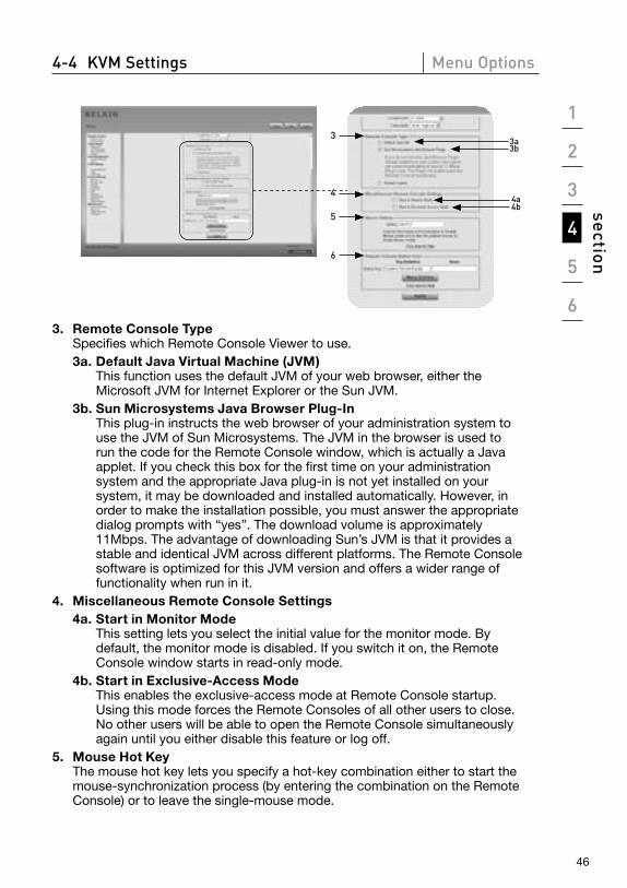
3. Remote Console Type Specifies which Remote Console Viewer to use. 3a. Default Java Virtual Machine (JVM)
This function uses the default JVM of your web browser, either the Microsoft JVM for Internet Explorer or the Sun JVM.
3b. Sun Microsystems Java Browser Plug-In This plug-in instructs the web browser of your administration system to use the JVM of Sun Microsystems. The JVM in the browser is used to run the code for the Remote Console window, which is actually a Java applet. If you check this box for the first time on your administration system and the appropriate Java plug-in is not yet installed on your system, it may be downloaded and installed automatically. However, in order to make the installation possible, you must answer the appropriate dialog prompts with “yes”. The download volume is approximately 11Mbps. The advantage of downloading Sun’s JVM is that it provides a stable and identical JVM across different platforms. The Remote Console software is optimized for this JVM version and offers a wider range of functionality when run in it.
4. Miscellaneous Remote Console Settings 4a. Start in Monitor Mode
This setting lets you select the initial value for the monitor mode. By default, the monitor mode is disabled. If you switch it on, the Remote Console window starts in read-only mode.
4b. Start in Exclusive-Access Mode This enables the exclusive-access mode at Remote Console startup.
Using this mode forces the Remote Consoles of all other users to close. No other users will be able to open the Remote Console simultaneously again until you either disable this feature or log off.
5. Mouse Hot Key The mouse hot key lets you specify a hot-key combination either to start the mouse-synchronization process (by entering the combination on the Remote Console) or to leave the single-mouse mode.
47
4-4 KVM Settings Menu Options
6. Remote Console Button Keys The button keys allow simulating keystrokes on the remote system that cannot be generated locally. This might be necessary if there is a key missing or if the local operating system of the Remote Console is unconditionally catching a keystroke. Typical examples are “Control+Alt+Delete” on Windows and DOS, which are always caught, or the key sequence “Control+Backspace” on Linux, which can be used for terminating the X server. In order to define a new button key, or to adjust an existing one, refer to the rules that describe the setting for a key. In general, the syntax for a key is as follows:
[confirm] <keycode>[+|-|<[*]<keycode>]* A term in brackets is optional. The star at the end means that you must add
further keys as often as required for your case. The term “confirm” adds a confirmation dialogue that is displayed before the keystrokes can be sent to the remote host. The “keycode” is the key to be sent. Multiple key codes can be concatenated with a plus, a minus, or a “<” sign. The plus sign builds key combinations—all the keys will be pressed until a minus sign or the end of the combination is encountered. In such a case, all pressed keys will be released in reversed sequence. So, the minus sign builds single, separate key presses and key releases. The “<” sign releases the last key only. The star inserts a pause with a duration of 100 milliseconds. As an example, the key combination of Ctrl, Alt, and F2 is represented by the sequence “Ctrl+Alt+F2”.
1
2
3
4
5
6
section
48
4-4 KVM Settings Menu Options
Keyboard/Mouse
1
2
34
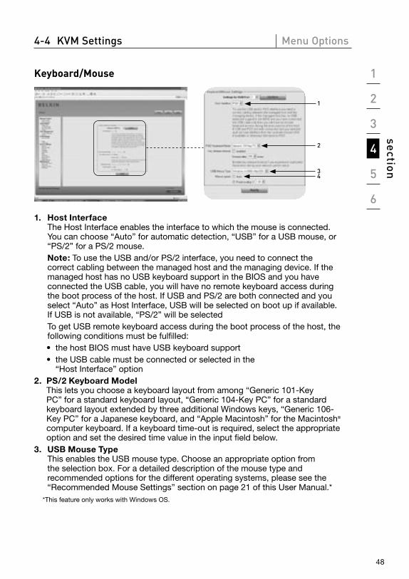
1. Host Interface The Host Interface enables the interface to which the mouse is connected. You can choose “Auto” for automatic detection, “USB” for a USB mouse, or “PS/2” for a PS/2 mouse.
Note: To use the USB and/or PS/2 interface, you need to connect the correct cabling between the managed host and the managing device. If the managed host has no USB keyboard support in the BIOS and you have connected the USB cable, you will have no remote keyboard access during the boot process of the host. If USB and PS/2 are both connected and you select “Auto” as Host Interface, USB will be selected on boot up if available. If USB is not available, “PS/2” will be selected
To get USB remote keyboard access during the boot process of the host, the following conditions must be fulfilled:
• the host BIOS must have USB keyboard support • the USB cable must be connected or selected in the
“Host Interface” option2. PS/2 Keyboard Model
This lets you choose a keyboard layout from among “Generic 101-Key PC” for a standard keyboard layout, “Generic 104-Key PC” for a standard keyboard layout extended by three additional Windows keys, “Generic 106-Key PC” for a Japanese keyboard, and “Apple Macintosh” for the Macintosh® computer keyboard. If a keyboard time-out is required, select the appropriate option and set the desired time value in the input field below.
3. USB Mouse Type This enables the USB mouse type. Choose an appropriate option from the selection box. For a detailed description of the mouse type and recommended options for the different operating systems, please see the “Recommended Mouse Settings” section on page 21 of this User Manual.*
*This feature only works with Windows OS.
49
4-4 KVM Settings Menu Options
4. Mouse Speed • Auto Mouse Speed
Use this option if the mouse settings on the host use an additional acceleration setting. The RIPM detects the acceleration and speed of the mouse during the mouse-sync process.
• Fixed Mouse Speed Use this option for a direct translation of mouse movements between the local and the remote pointer. You may also set a fixed scaling that determines the amount the remote mouse pointer is moved when the local mouse pointer is moved by one pixel. This option works only when the mouse settings on the host are linear, i.e., when there is no mouse acceleration involved.
To set the options, click the “Apply” button.
1
2
3
4
5
6
section
50
4-4 KVM Settings Menu Options
Video
3
1
22a
3b3a3c 3d3e 3f
3g
2b
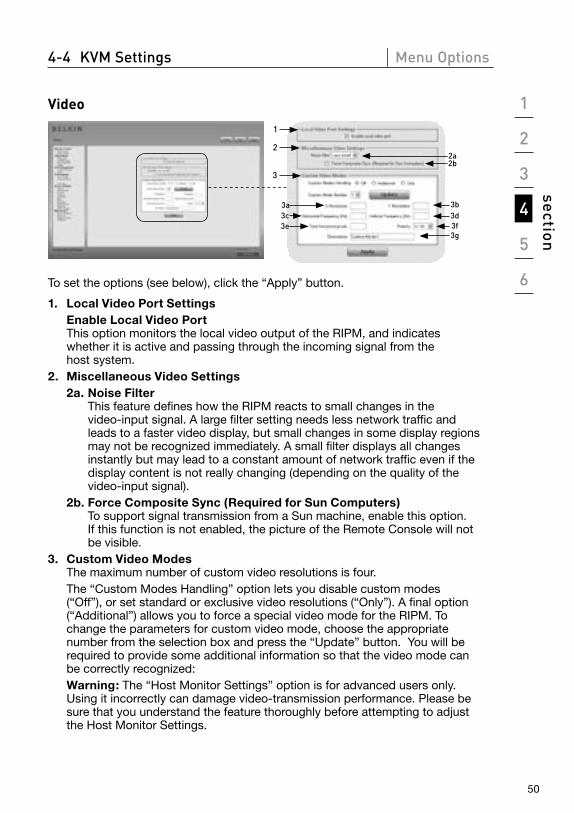
To set the options (see below), click the “Apply” button.
1. Local Video Port Settings Enable Local Video Port
This option monitors the local video output of the RIPM, and indicates whether it is active and passing through the incoming signal from the host system.
2. Miscellaneous Video Settings 2a. Noise Filter
This feature defines how the RIPM reacts to small changes in the video-input signal. A large filter setting needs less network traffic and leads to a faster video display, but small changes in some display regions may not be recognized immediately. A small filter displays all changes instantly but may lead to a constant amount of network traffic even if the display content is not really changing (depending on the quality of the video-input signal).
2b. Force Composite Sync (Required for Sun Computers) To support signal transmission from a Sun machine, enable this option. If this function is not enabled, the picture of the Remote Console will not be visible.
3. Custom Video Modes The maximum number of custom video resolutions is four.
The “Custom Modes Handling” option lets you disable custom modes (“Off”), or set standard or exclusive video resolutions (“Only”). A final option (“Additional”) allows you to force a special video mode for the RIPM. To change the parameters for custom video mode, choose the appropriate number from the selection box and press the “Update” button. You will be required to provide some additional information so that the video mode can be correctly recognized:
Warning: The “Host Monitor Settings” option is for advanced users only. Using it incorrectly can damage video-transmission performance. Please be sure that you understand the feature thoroughly before attempting to adjust the Host Monitor Settings.
51
4-4 KVM Settings Menu Options
3a. X Resolution This refers to the visible number of horizontal pixels.
3b. Y Resolution This refers to the visible number of vertical pixels.
3c. Horizontal Frequency (Hz) This refers to the horizontal (line) frequency in hertz.
3d. Vertical Frequency (Hz) This refers to the vertical (refresh) frequency in hertz.
3e. Total horizontal pixels This refers to the total number of pixels per line, including the non-visible and blanking area.
3f. Polarity This refers to the positive or negative characteristic of the synchronization signals. V indicates vertical polarity; H indicates horizontal polarity.
3g. Description Here you can provide a mode name, which is displayed in the Remote Console if custom mode is activated.
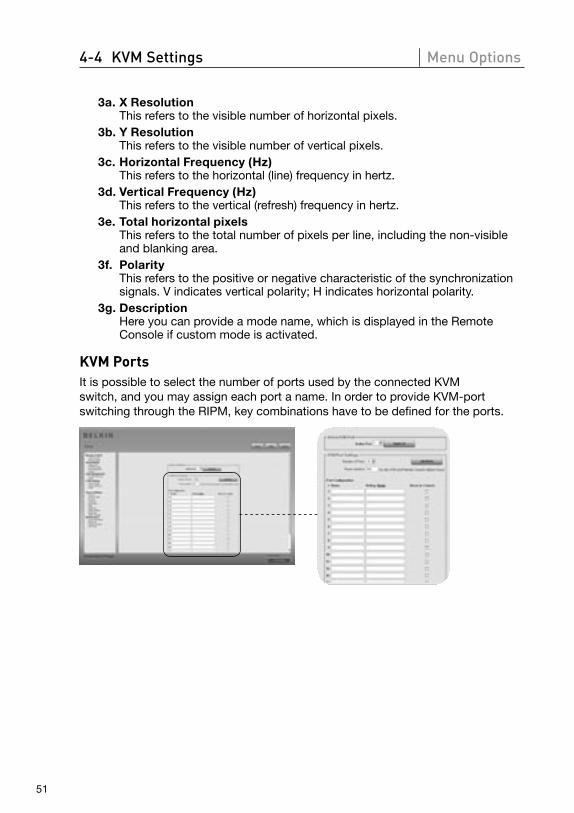
KVM PortsIt is possible to select the number of ports used by the connected KVM switch, and you may assign each port a name. In order to provide KVM-port switching through the RIPM, key combinations have to be defined for the ports.
1
2
3
4
5
6
section
52
4-5 Device Settings Menu Options
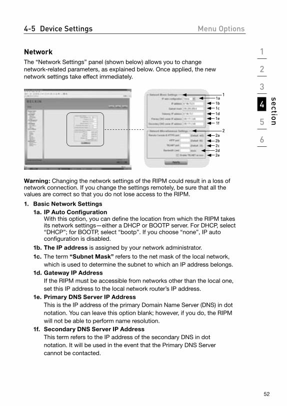
NetworkThe “Network Settings” panel (shown below) allows you to change network-related parameters, as explained below. Once applied, the new network settings take effect immediately.
11a1b1c1d1e1f
22a2b2c2d2e
Warning: Changing the network settings of the RIPM could result in a loss of network connection. If you change the settings remotely, be sure that all the values are correct so that you do not lose access to the RIPM.
1. Basic Network Settings 1a. IP Auto Configuration
With this option, you can define the location from which the RIPM takes its network settings—either a DHCP or BOOTP server. For DHCP, select “DHCP”; for BOOTP, select “bootp”. If you choose “none”, IP auto configuration is disabled.
1b. The IP address is assigned by your network administrator.
1c. The term “Subnet Mask” refers to the net mask of the local network, which is used to determine the subnet to which an IP address belongs.
1d. Gateway IP Address If the RIPM must be accessible from networks other than the local one, set this IP address to the local network router’s IP address.
1e. Primary DNS Server IP Address This is the IP address of the primary Domain Name Server (DNS) in dot notation. You can leave this option blank; however, if you do, the RIPM will not be able to perform name resolution.
1f. Secondary DNS Server IP Address This term refers to the IP address of the secondary DNS in dot notation. It will be used in the event that the Primary DNS Server cannot be contacted.

53
4-5 Device Settings Menu Options
2. Network Miscellaneous Settings 2a. Remote Console and HTTPS Port
This is the port number at which the RIPM’s Remote Console server and HTTPS server are listening. If left empty, the default value will be used.
2b. HTTP Port This is the port number at which the RIPM’s HTTP server is listening. If left empty, the default value will be used.
2c. Telnet Port This refers to the port number at which the RIPM’s Telnet server is listening. If left empty, the default value will be used.
2d. Bandwidth Limit This option refers to the maximum network traffic generated through the RIPM Ethernet device (value in Kbps).
2e. Enable Telnet Access Set this option to allow users to access the RIPM using the Telnet gateway (see the “Telnet Console” section on page 32).
1
2
3
4
5
6
section
54
4-5 Device Settings Menu Options
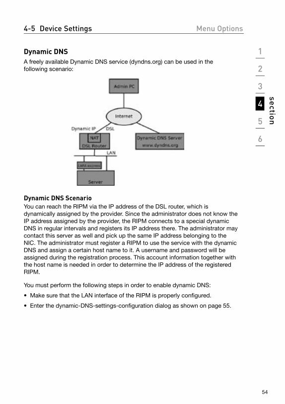
Dynamic DNSA freely available Dynamic DNS service (dyndns.org) can be used in the following scenario:
Dynamic DNS Scenario You can reach the RIPM via the IP address of the DSL router, which is dynamically assigned by the provider. Since the administrator does not know the IP address assigned by the provider, the RIPM connects to a special dynamic DNS in regular intervals and registers its IP address there. The administrator may contact this server as well and pick up the same IP address belonging to the NIC. The administrator must register a RIPM to use the service with the dynamic DNS and assign a certain host name to it. A username and password will be assigned during the registration process. This account information together with the host name is needed in order to determine the IP address of the registered RIPM.
You must perform the following steps in order to enable dynamic DNS:
• Make sure that the LAN interface of the RIPM is properly configured.
• Enter the dynamic-DNS-settings-configuration dialog as shown on page 55.
55
4-5 Device Settings Menu Options
Dynamic DNS Settiings
12
345678
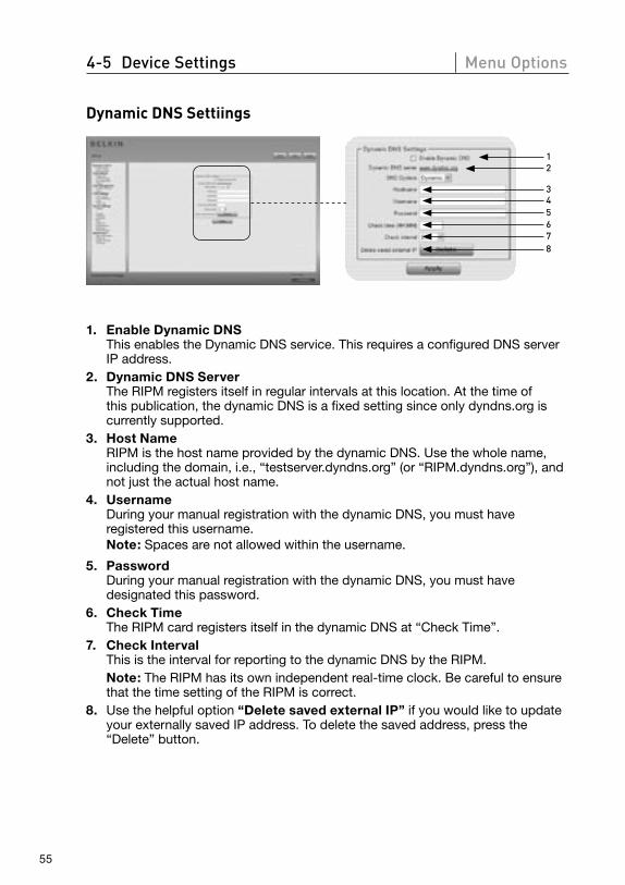
1. Enable Dynamic DNS This enables the Dynamic DNS service. This requires a configured DNS server IP address.
2. Dynamic DNS Server The RIPM registers itself in regular intervals at this location. At the time of this publication, the dynamic DNS is a fixed setting since only dyndns.org is currently supported.
3. Host Name RIPM is the host name provided by the dynamic DNS. Use the whole name, including the domain, i.e., “testserver.dyndns.org” (or “RIPM.dyndns.org”), and not just the actual host name.
4. Username During your manual registration with the dynamic DNS, you must have registered this username. Note: Spaces are not allowed within the username.
5. Password During your manual registration with the dynamic DNS, you must have designated this password.
6. Check Time The RIPM card registers itself in the dynamic DNS at “Check Time”.
7. Check Interval This is the interval for reporting to the dynamic DNS by the RIPM.
Note: The RIPM has its own independent real-time clock. Be careful to ensure that the time setting of the RIPM is correct.
8. Use the helpful option “Delete saved external IP” if you would like to update your externally saved IP address. To delete the saved address, press the “Delete” button.
1
2
3
4
5
6
section
56
4-5 Device Settings Menu Options
Security
1
2
2f 2g 2h 2i3
1a1b
2a2b
3b3a
2c 2d 2e
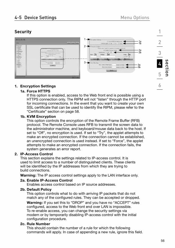
1. Encryption Settings 1a. Force HTTPS
If this option is enabled, access to the Web front end is possible using a HTTPS connection only. The RIPM will not “listen” through the HTTP port for incoming connections. In the event that you want to create your own SSL certificate that can be used to identify the RIPM, please refer to the “Certificate” section on page 58.
1b. KVM Encryption This option controls the encryption of the Remote Frame Buffer (RFB) protocol. The Remote Console uses RFB to transmit the screen data to the administrator machine, and keyboard/mouse data back to the host. If set to “Off”, no encryption is used. If set to “Try”, the applet attempts to make an encrypted connection. If the connection cannot be established, an unencrypted connection is used instead. If set to “Force”, the applet attempts to make an encrypted connection. If the connection fails, the system generates an error report.
2. IP-Access Control This section explains the settings related to IP-access control. It is
used to limit access to a number of distinguished clients. These clients will be identified by the IP addresses from which they are trying to build connections.
Warning: The IP access control settings apply to the LAN interface only. 2a. Enable IP-Access Control
Enables access control based on IP source addresses. 2b. Default Policy
This option controls what to do with arriving IP packets that do not match any of the configured rules. They can be accepted or dropped.
Warning: If you set this to “DROP” and you have no “ACCEPT” rules configured, access to the Web front end over LAN is impossible. To re-enable access, you can change the security settings via modem or by temporarily disabling IP-access control with the initial configuration procedure.
2c. Rule Number This should contain the number of a rule for which the following commands will apply. In case of appending a new rule, ignore this field.
57
4-5 Device Settings Menu Options
2d. IP/Mask Specifies the IP address or IP-address range for which the rule applies. In the following examples, the number concatenated to an IP address with a “ / ” represents the number of valid bits of the given IP address that will be used.
192.168.1.22/32 matches the IP address 192.168.1.22 192.168.1.0/24 matches all IP packets with source addresses from
192.168.1.0 to 192.168.1.255 0.0.0.0/0 matches any IP packet 2e. Policy
The policy determines what to do with matching packets. They can be either accepted or dropped.
Warning: The order of the rules is important. The rules are checked in ascending order until a rule matches. All the rules below the matching one will be ignored. The default policy applies if no match has been found.
2f. Appending a Rule Enter the IP/mask and set the policy. Finally, press the “Append” button.
2g. Inserting a Rule Enter the rule number and the IP/mask. Set the policy. Finally, press the “Insert” button
2h. Replacing a Rule Enter the rule number and the IP/mask. Set the policy. Finally, press the “Replace” button.
2i. Deleting a Rule Enter the rule number and press the “Delete” button.
3. User Blocking The user-blocking mechanism allows the administrator to disable the login of a certain user if his or her password was entered incorrectly a specific number of times. The duration of the blocking is also configurable.
3a. Maximum Number of Failed Logins Enter the maximum number of failed login attempts after which a user should be blocked. Leave this field empty to disable the user-blocking feature.
3b. Block Time The number of minutes the user is blocked after he or she has exceeded the maximum number of failed login attempts. Leave this field empty to block this user until he or she is manually unblocked.
Unblocking Users There are two possibilities to unblock a blocked user:
• A parent user may go to the user-management settings (see the “User Management” section) and press the “Unblock” button for the user.
• An administrator may use the serial console for the initial configuration and log in as the user “unblock”. The RIPM will ask for the administrator password and present a list of blocked users who may be unblocked.
1
2
3
4
5
6
section
58
4-5 Device Settings Menu Options
Certificate
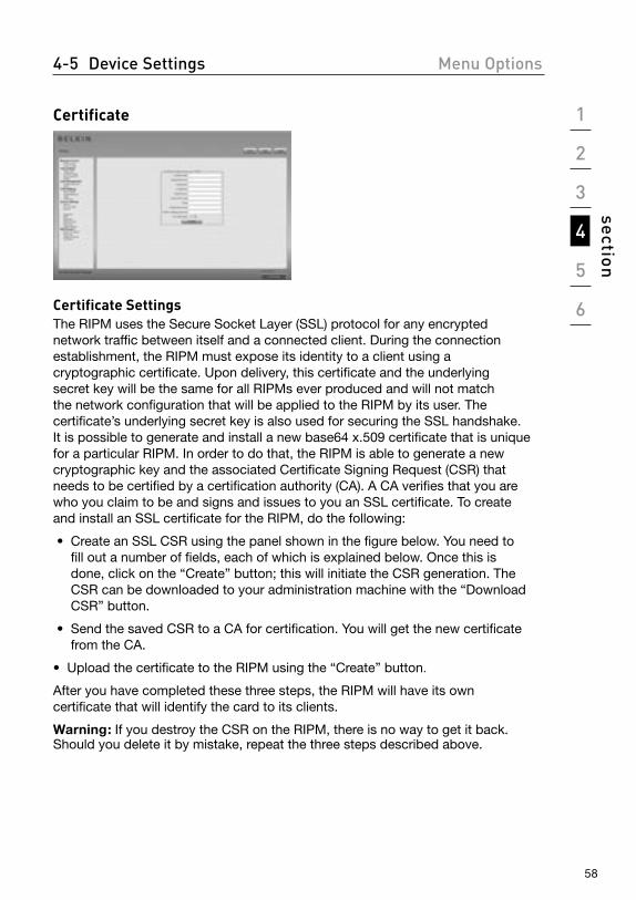
Certificate SettingsThe RIPM uses the Secure Socket Layer (SSL) protocol for any encrypted network traffic between itself and a connected client. During the connection establishment, the RIPM must expose its identity to a client using a cryptographic certificate. Upon delivery, this certificate and the underlying secret key will be the same for all RIPMs ever produced and will not match the network configuration that will be applied to the RIPM by its user. The certificate’s underlying secret key is also used for securing the SSL handshake. It is possible to generate and install a new base64 x.509 certificate that is unique for a particular RIPM. In order to do that, the RIPM is able to generate a new cryptographic key and the associated Certificate Signing Request (CSR) that needs to be certified by a certification authority (CA). A CA verifies that you are who you claim to be and signs and issues to you an SSL certificate. To create and install an SSL certificate for the RIPM, do the following:
• Create an SSL CSR using the panel shown in the figure below. You need to fill out a number of fields, each of which is explained below. Once this is done, click on the “Create” button; this will initiate the CSR generation. The CSR can be downloaded to your administration machine with the “Download CSR” button.
• Send the saved CSR to a CA for certification. You will get the new certificate from the CA.
• Upload the certificate to the RIPM using the “Create” button.
After you have completed these three steps, the RIPM will have its own certificate that will identify the card to its clients.
Warning: If you destroy the CSR on the RIPM, there is no way to get it back. Should you delete it by mistake, repeat the three steps described above.
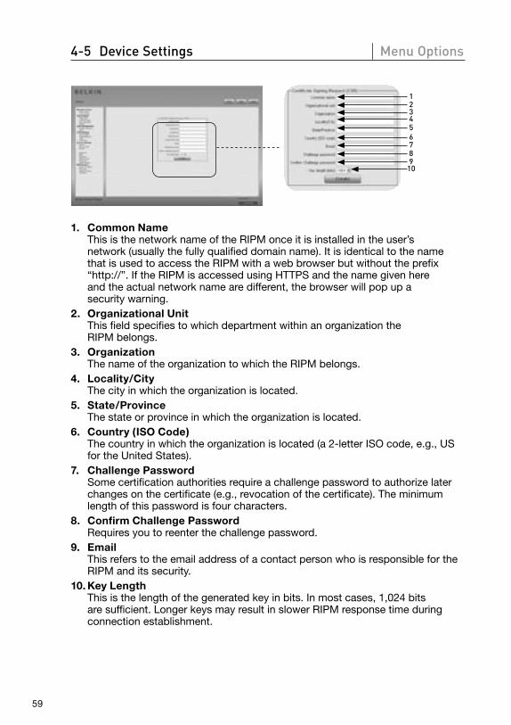
59
4-5 Device Settings Menu Options
123456789
10
1. Common Name This is the network name of the RIPM once it is installed in the user’s network (usually the fully qualified domain name). It is identical to the name that is used to access the RIPM with a web browser but without the prefix “http://”. If the RIPM is accessed using HTTPS and the name given here and the actual network name are different, the browser will pop up a security warning.
2. Organizational Unit This field specifies to which department within an organization the RIPM belongs.
3. Organization The name of the organization to which the RIPM belongs.
4. Locality/City The city in which the organization is located.
5. State/Province The state or province in which the organization is located.
6. Country (ISO Code) The country in which the organization is located (a 2-letter ISO code, e.g., US for the United States).
7. Challenge Password Some certification authorities require a challenge password to authorize later changes on the certificate (e.g., revocation of the certificate). The minimum length of this password is four characters.
8. Confirm Challenge Password Requires you to reenter the challenge password.
9. Email This refers to the email address of a contact person who is responsible for the RIPM and its security.
10. Key Length This is the length of the generated key in bits. In most cases, 1,024 bits are sufficient. Longer keys may result in slower RIPM response time during connection establishment.
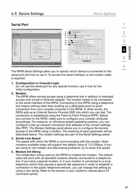
1
2
3
4
5
6
section
60
4-5 Device Settings Menu Options
Serial Port
1234
567
The RIPM Serial Settings allow you to specify which device is connected to the serial port and how to use it. To access the serial interface, a null modem cable is required.
1. Configuration or Console Login Do not use the serial port for any special function; use it only for the initial configuration.
2. Modem The RIPM offers remote access using a telephone line in addition to standard access over a built-in Ethernet adapter. The modem needs to be connected to the serial interface of the RIPM. Connecting to the RIPM using a telephone line means nothing other than building up a dedicated point-to-point connection from your console computer to the RIPM. In other words, the RIPM acts as an Internet Service Provider (ISP) into which you can dial. The connection is established using the Point-to-Point Protocol (PPP). Before you connect to the RIPM, make sure to configure your console computer accordingly. For instance, on Windows-based operating systems, you can configure a dial-up network connection that defaults to the correct settings (like PPP). The Modem Settings panel allows you to configure the remote access to the RIPM using a modem. The meaning of each parameter will be described below. The modem settings are part of the Serial Settings panel.
3. Serial-Line Speed The speed with which the RIPM is communicating with the modem. Most modems available today will support the default value of 115.200bps. If you are using an old modem and discovering problems, try to lower this speed.
4. Modem Init String The initialization string used by the RIPM to initialize the modem. The default value will work with all standard modems directly connected to a telephone line. If you have a special modem, or if your modem is connected to a local telephone switch that requires a special dial sequence in order to establish a connection to the public telephone network, you can change this setting by using a new string. Refer to the section in your modem’s manual about AT command syntax.
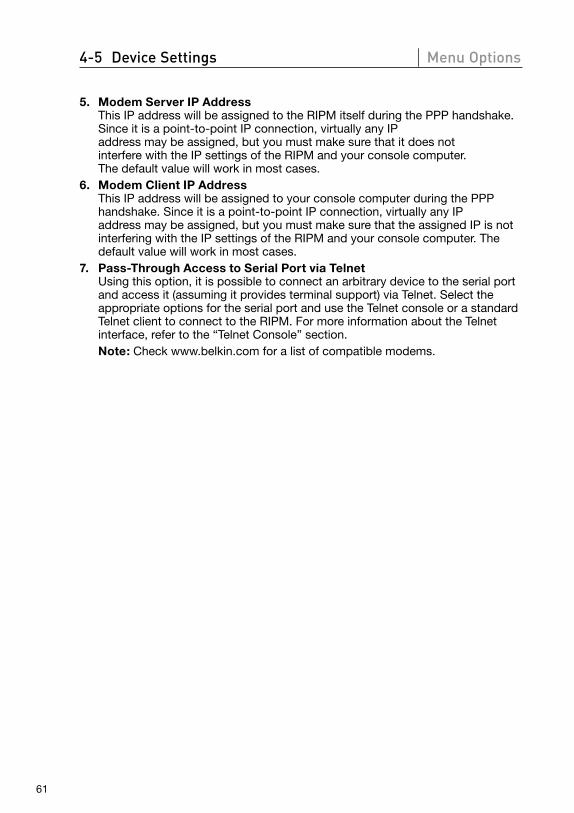
61
4-5 Device Settings Menu Options
5. Modem Server IP Address This IP address will be assigned to the RIPM itself during the PPP handshake. Since it is a point-to-point IP connection, virtually any IP address may be assigned, but you must make sure that it does not interfere with the IP settings of the RIPM and your console computer. The default value will work in most cases.
6. Modem Client IP Address This IP address will be assigned to your console computer during the PPP handshake. Since it is a point-to-point IP connection, virtually any IP address may be assigned, but you must make sure that the assigned IP is not interfering with the IP settings of the RIPM and your console computer. The default value will work in most cases.
7. Pass-Through Access to Serial Port via Telnet Using this option, it is possible to connect an arbitrary device to the serial port and access it (assuming it provides terminal support) via Telnet. Select the appropriate options for the serial port and use the Telnet console or a standard Telnet client to connect to the RIPM. For more information about the Telnet interface, refer to the “Telnet Console” section.
Note: Check www.belkin.com for a list of compatible modems.
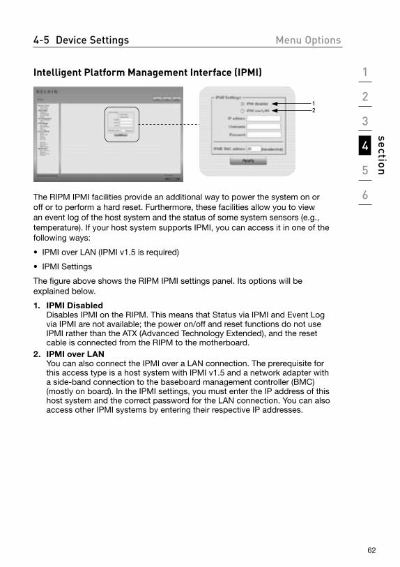
1
2
3
4
5
6
section
62
4-5 Device Settings Menu Options
Intelligent Platform Management Interface (IPMI)
21
The RIPM IPMI facilities provide an additional way to power the system on or off or to perform a hard reset. Furthermore, these facilities allow you to view an event log of the host system and the status of some system sensors (e.g., temperature). If your host system supports IPMI, you can access it in one of the following ways:
• IPMI over LAN (IPMI v1.5 is required)
• IPMI Settings
The figure above shows the RIPM IPMI settings panel. Its options will be explained below.
1. IPMI Disabled Disables IPMI on the RIPM. This means that Status via IPMI and Event Log via IPMI are not available; the power on/off and reset functions do not use IPMI rather than the ATX (Advanced Technology Extended), and the reset cable is connected from the RIPM to the motherboard.
2. IPMI over LAN You can also connect the IPMI over a LAN connection. The prerequisite for this access type is a host system with IPMI v1.5 and a network adapter with a side-band connection to the baseboard management controller (BMC) (mostly on board). In the IPMI settings, you must enter the IP address of this host system and the correct password for the LAN connection. You can also access other IPMI systems by entering their respective IP addresses.
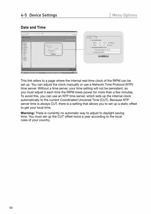
63
4-5 Device Settings Menu Options
Date and Time
This link refers to a page where the internal real-time clock of the RIPM can be set up. You can adjust the clock manually or use a Network Time Protocol (NTP) time server. Without a time server, your time setting will not be persistent, so you must adjust it each time the RIPM loses power for more than a few minutes. To avoid this, you can use an NTP time server, which sets up the internal clock automatically to the current Coordinated Universal Time (CUT). Because NTP server time is always CUT, there is a setting that allows you to set up a static offset to get your local time.
Warning: There is currently no automatic way to adjust to daylight saving time. You must set up the CUT offset twice a year according to the local rules of your country.
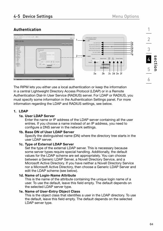
1
2
3
4
5
6
section
64
4-5 Device Settings Menu Options
Authentication
11a1b1c1d1e1f1g
2
2a 2b 2c 2d 2e 2f
The RIPM lets you either use a local authentication or keep the information in a central Lightweight Directory Access Protocol (LDAP) or in a Remote Authentication Dial-In User Service (RADIUS) server. For LDAP or RADIUS, you must specify some information in the Authentication Settings panel. For more information regarding the LDAP and RADIUS settings, see below.
1. LDAP 1a. User LDAP Server
Enter the name or IP address of the LDAP server containing all the user entries. If you choose a name instead of an IP address, you need to configure a DNS server in the network settings.
1b. Base DN of User LDAP Server Specify the distinguished name (DN) where the directory tree starts in the user LDAP server.
1c. Type of External LDAP Server Set the type of the external LDAP server. This is necessary because some server types require special handling. Additionally, the default values for the LDAP scheme are set appropriately. You can choose between a Generic LDAP Server, a Novell Directory Service, and a Microsoft Active Directory. If you have neither a Novell Directory Service nor a Microsoft Active Directory, then choose a Generic LDAP Server and edit the LDAP scheme (see below).
1d. Name of Login-Name Attribute This is the name of the attribute containing the unique login name of a user. To use the default, leave this field empty. The default depends on the selected LDAP server type.
1e. Name of User-Entry Object Class This is the object class that identifies a user in the LDAP directory. To use the default, leave this field empty. The default depends on the selected LDAP server type.

65
4-5 Device Settings Menu Options
1f. User Search Sub-Filter Here you can refine the search for users that should be known to the RIPM.
1g. Active Directory Domain This option represents the active directory domain that is configured in the Microsoft Active Directory server. This option is only valid if you have chosen a Microsoft Active Directory as the LDAP server type.
2. Remote Authentication Dial In User Service (RADIUS) RADIUS is a protocol specified by the Internet Engineering Task Force (IETF) working group. There are two specifications that make up the RADIUS protocol suite: authentication and accounting. These specifications aim to centralize authentication, configuration, and accounting for dial-in services to an independent server. The RADIUS protocol exists in several implementations such as free RADIUS, open-RADIUS, or RADIUS on UNIX systems. The RADIUS protocol is well specified and tested. We can give a recommendation for all products listed above, especially for the free RADIUS implementation.
Note: Currently, we do not support challenge/response. An “Access Challenge” response is seen and evaluated as an “Access Reject”.
To access a remote device using the RADIUS protocol, you must log in. You will be asked to specify your username and password. The RADIUS server will read your input data (Authentication), and the RIPM will look for your profile (Authorization). The profile defines (or limits) your actions and may differ depending on your specific situation. If there is no such profile, your access via RADIUS will be refused. In terms of the remote-activity mechanism, the login via RADIUS works like the Remote Console. If there is no activity for half an hour, your connection to the RIPM will be interrupted and closed.
2a. Server Enter either the IP address or the host name of the RADIUS server to be connected. If you are using the host name, DNS must be configured and enabled.
2b. Shared Secret A shared secret is a text string that serves as a password between the RADIUS client and RADIUS server. The RIPM serves as a RADIUS client. A shared secret is used to verify that RADIUS messages are sent by a RADIUS-enabled device that is configured with the same shared secret and to verify that the RADIUS message has not been modified in transit (i.e., to verify message integrity). For the shared secret, you can use any standard alphanumeric and special characters. A shared secret may consist of up to 128 characters and may contain both lowercase and uppercase letters (A–Z, a–z), numerals (0–9), and other symbols (characters not defined as letters or numerals), such as exclamation points (“ ! ”) or asterisks (“ * ”).
2c. Authentication Port The port the RADIUS server listens to for authentication requests. The default value is #1812.
1
2
3
4
5
6
section
66
4-5 Device Settings Menu Options
2d. Accounting Port The port the RADIUS server listens to for accounting requests. The default value is #1813.
2e. Timeout Sets the request time-to-live in seconds. The time-to-live is the time to wait for the completion of the request. If the request job is not completed within this interval of time, it is canceled. The default value is one second.
2f. Retries Sets the number of retries if a request could not be completed. The default value is three times.
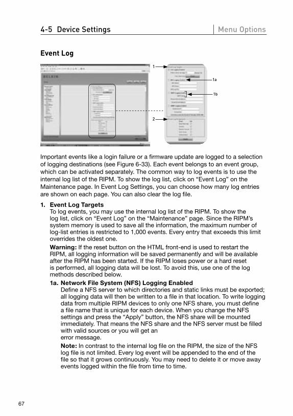
67
4-5 Device Settings Menu Options
Event Log
1
1a
1b
2
Important events like a login failure or a firmware update are logged to a selection of logging destinations (see Figure 6-33). Each event belongs to an event group, which can be activated separately. The common way to log events is to use the internal log list of the RIPM. To show the log list, click on “Event Log” on the Maintenance page. In Event Log Settings, you can choose how many log entries are shown on each page. You can also clear the log file.
1. Event Log Targets To log events, you may use the internal log list of the RIPM. To show the log list, click on “Event Log” on the “Maintenance” page. Since the RIPM’s system memory is used to save all the information, the maximum number of log-list entries is restricted to 1,000 events. Every entry that exceeds this limit overrides the oldest one.
Warning: If the reset button on the HTML front-end is used to restart the RIPM, all logging information will be saved permanently and will be available after the RIPM has been started. If the RIPM loses power or a hard reset is performed, all logging data will be lost. To avoid this, use one of the log methods described below.
1a. Network File System (NFS) Logging Enabled Define a NFS server to which directories and static links must be exported; all logging data will then be written to a file in that location. To write logging data from multiple RIPM devices to only one NFS share, you must define a file name that is unique for each device. When you change the NFS settings and press the “Apply” button, the NFS share will be mounted immediately. That means the NFS share and the NFS server must be filled with valid sources or you will get an error message.
Note: In contrast to the internal log file on the RIPM, the size of the NFS log file is not limited. Every log event will be appended to the end of the file so that it grows continuously. You may need to delete it or move away events logged within the file from time to time.
1
2
3
4
5
6
section
68
4-5 Device Settings Menu Options
1b. SNMP Settings Simple Mail Transfer Protocol (SMTP) Logging Enabled
With this option, the RIPM is able to send email to an address entered into the email-address text field in Event Log Settings. These mails contain the same description strings as the internal log file, and the mail subject is filled with the event group of the occurred log event. In order to use this log destination, you must specify an SMTP server that is both reachable from the RIPM and needs no authentication (<serverip>:<port>).
SNMP Logging Enabled If this is activated, the RIPM sends an SNMP trap to a specified IP address every time a log event occurs. If the receiver requires a community string, you can set it in the appropriate field. Most of the event traps contain only one descriptive string that contains all information about the log event. Authentication and host power have their own standard trap, which they automatically create and which consists of several fields detailing information about the event. To receive this SNMP trap, use any SNMP trap listener.
2. Event Log Assignments You may choose which actions of the RIPM will be saved in the log file. Check the desired box(es) and click “Apply” to confirm your selection.
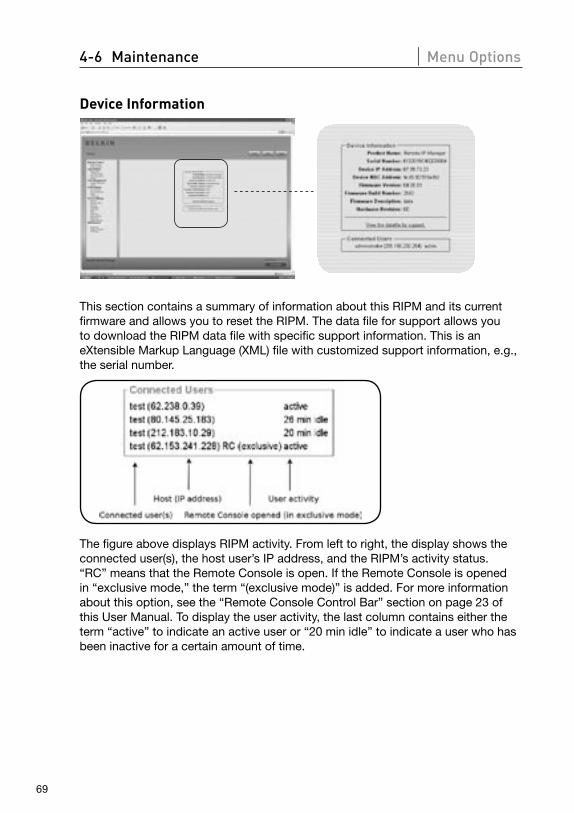
4-6 Maintenance Menu Options
69
Device Information
This section contains a summary of information about this RIPM and its current firmware and allows you to reset the RIPM. The data file for support allows you to download the RIPM data file with specific support information. This is an eXtensible Markup Language (XML) file with customized support information, e.g., the serial number.
The figure above displays RIPM activity. From left to right, the display shows the connected user(s), the host user’s IP address, and the RIPM’s activity status. “RC” means that the Remote Console is open. If the Remote Console is opened in “exclusive mode,” the term “(exclusive mode)” is added. For more information about this option, see the “Remote Console Control Bar” section on page 23 of this User Manual. To display the user activity, the last column contains either the term “active” to indicate an active user or “20 min idle” to indicate a user who has been inactive for a certain amount of time.
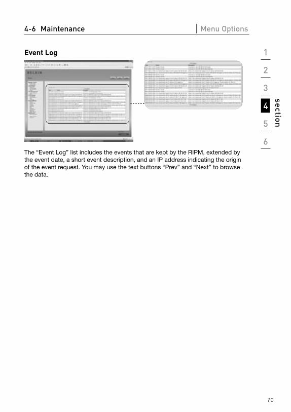
1
2
3
4
5
6
section
4-6 Maintenance Menu Options
70
Event Log
The “Event Log” list includes the events that are kept by the RIPM, extended by the event date, a short event description, and an IP address indicating the origin of the event request. You may use the text buttons “Prev” and “Next” to browse the data.
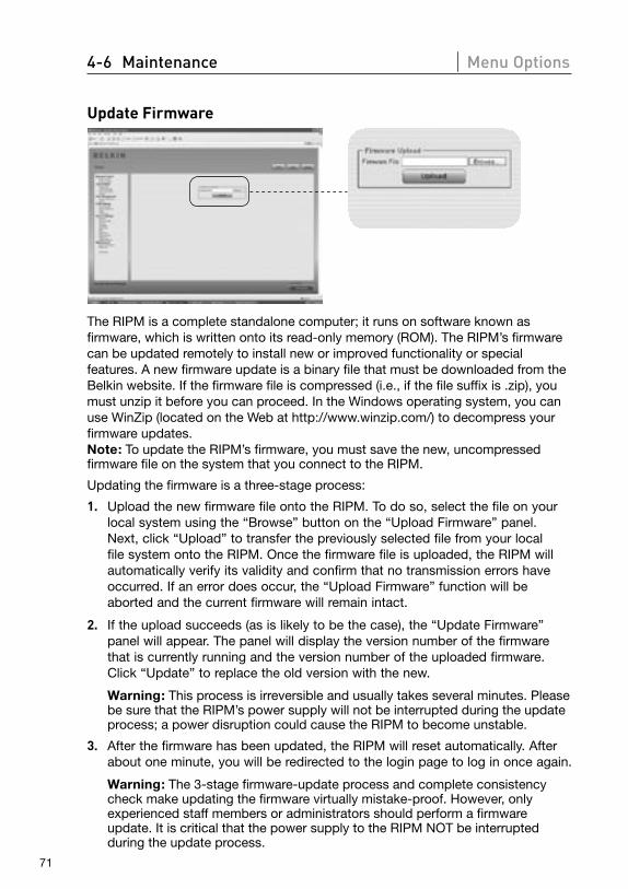
4-6 Maintenance Menu Options
71
Update Firmware
The RIPM is a complete standalone computer; it runs on software known as firmware, which is written onto its read-only memory (ROM). The RIPM’s firmware can be updated remotely to install new or improved functionality or special features. A new firmware update is a binary file that must be downloaded from the Belkin website. If the firmware file is compressed (i.e., if the file suffix is .zip), you must unzip it before you can proceed. In the Windows operating system, you can use WinZip (located on the Web at http://www.winzip.com/) to decompress your firmware updates. Note: To update the RIPM’s firmware, you must save the new, uncompressed firmware file on the system that you connect to the RIPM.
Updating the firmware is a three-stage process:
1. Upload the new firmware file onto the RIPM. To do so, select the file on your local system using the “Browse” button on the “Upload Firmware” panel. Next, click “Upload” to transfer the previously selected file from your local file system onto the RIPM. Once the firmware file is uploaded, the RIPM will automatically verify its validity and confirm that no transmission errors have occurred. If an error does occur, the “Upload Firmware” function will be aborted and the current firmware will remain intact.
2. If the upload succeeds (as is likely to be the case), the “Update Firmware” panel will appear. The panel will display the version number of the firmware that is currently running and the version number of the uploaded firmware. Click “Update” to replace the old version with the new.
Warning: This process is irreversible and usually takes several minutes. Please be sure that the RIPM’s power supply will not be interrupted during the update process; a power disruption could cause the RIPM to become unstable.
3. After the firmware has been updated, the RIPM will reset automatically. After about one minute, you will be redirected to the login page to log in once again.
Warning: The 3-stage firmware-update process and complete consistency check make updating the firmware virtually mistake-proof. However, only experienced staff members or administrators should perform a firmware update. It is critical that the power supply to the RIPM NOT be interrupted during the update process.
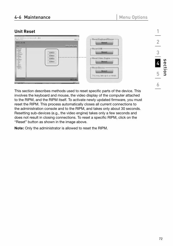
1
2
3
4
5
6
section
4-6 Maintenance Menu Options
72
Unit Reset
This section describes methods used to reset specific parts of the device. This involves the keyboard and mouse, the video display of the computer attached to the RIPM, and the RIPM itself. To activate newly updated firmware, you must reset the RIPM. This process automatically closes all current connections to the administration console and to the RIPM, and takes only about 30 seconds. Resetting sub-devices (e.g., the video engine) takes only a few seconds and does not result in closing connections. To reset a specific RIPM, click on the “Reset” button as shown in the image above.
Note: Only the administrator is allowed to reset the RIPM.
73
5-0 Troubleshooting Guide
The remote mouse does not work or is not synchronous. First, check the VGA connection. Both the RIPM and the local monitor must
support the same video resolution. Make sure that your mouse settings match your mouse model, i.e., PS/2 or USB. Also, the mouse model must be set on both the RIPM and the host (the computer connected to the RIPM) operating system. In some circumstances, the mouse synchronization process can produce errors. Please refer to the “Mouse, Keyboard, and Video Configuration” section in Chapter 3 for further explanation.
The video quality is bad and/or grainy. Use the menu entry “Reset” to set the RIPM to its default values. Then, click
the “Auto-Adjust” button to select an appropriate video output. Check that the video cables are securely connected.
Login on the RIPM fails. Verify both your user login and your password. The default username is
“administrator”, and the default password is “belkin”. Make sure that your web browser is configured to accept cookies.
The RIPM’s Remote Console window does not open. Verify that Java has been loaded. A firewall may prevent access to the Remote
Console. The TCP ports #80 (for HTTP) and #443 (for both HTTPS and RFB) must be open (the server providing the firewall must accept incoming TCP connections on these ports).
The Remote Console is unable to connect and displays a time-out error. Verify your hardware and network setup. If there is a proxy server between
the RIPM and your host, then you may not be able to transfer the video data using RFB. Establish a direct connection between the RIPM and the client. In addition, check the settings of the RIPM and choose a different server port for RFB transfer. If you use a firewall, check the appropriate port for accepting connections. You may restrict these connections to the IP addresses used by the RIPM and your client.
No connection can be established to the RIPM. Inspect your hardware. Is the RIPM attached to a power supply? Verify your
network configuration (IP address, router). Send a “ping” request to the RIPM to find out whether the RIPM is reachable via network.
Special key combinations (e.g., ALT+F2, ALT+F3) are intercepted by the console system and not transmitted to the host. Define a so-called “button key”. This can be done in the Remote Console
settings (see the “Remote Console Control Bar” section on page 23.
1
2
3
4
5
6
section
74
5-0 Troubleshooting Guide
The RIPM web pages are not displayed correctly. Check your browser’s cache settings. Make sure the cache settings are NOT
set to “never check for newer pages”. Under that setting, the RIPM pages could be loaded from your browser cache and not from the RIPM, which may be causing the problem.
Windows XP does not awake from standby mode. This is possibly a Windows XP problem. Try not to move the mouse pointer
while XP switches into standby mode. Please consult the OS manual for additional information.
Every time I reopen the Remote Console dialog box, the mouse pointers are no longer synchronous. Disable the setting “Automatically move mouse pointer to the default button
of dialog boxes” in the mouse settings of your operating system.
The Remote Console remains black. Check whether the RIPM is USB-powered only. If there is not enough power
via USB, the Remote Console opens but remains black. Verify the RIPM settings on page 26 of this User Manual. Check that the video cables are securely connected.
The video data on the local monitor is surrounded by a black border. This is not a failure. The local monitor is programmed to a fixed video mode
that can be selected in the video settings of the RIPM. Refer to the “Remote Console Control Bar” section on page 23 of this User Manual.
I forgot my password. How can I reset the RIPM to factory defaults? You can use the serial interface. For a detailed description, see the
“Resetting the Remote IP Manager to Factory Settings” section on page 31 of this User Manual.
Please check www.belkin.com for additional troubleshooting and a list of hardware that is compatible with the RIPM.
Note: If any of these solutions do not remedy the situation, please call technical support at 1-800-2BELKIN.
75
6-0 Information
FCC Statement
Declaration of Conformity with FCC Rules for Electromagnetic Compatibility
We, Belkin Corporation, of 501 West Walnut Street, Compton, CA 90220, declare under our sole responsibility that the product:
F1DE101H
to which this declaration relates: Complies with Part 15 of the FCC Rules. Operation is subject to the following two conditions: (1) this device may not cause harmful interference, and (2) this device must accept any interference received, including interference that may cause undesired operation.
CE Declaration of ConformityWe, Belkin Corporation, declare under our sole responsibility that the product F1DE101H, to which this declaration relates, is in conformity with Emissions Standard EN55022 and with Immunity Standard EN55024, LVP EN61000-3-2, and EN61000-3-3.
ICESThis Class B digital apparatus complies with Canadian ICES-003. Cet appareil numérique de la classe B est conforme á la norme NMB-003 du Canada.
Belkin Corporation Limited 2-Year Product Warranty
What this warranty covers.Belkin Corporation warrants to the original purchaser of this Belkin product that the product shall be free of defects in design, assembly, material, or workmanship.
What the period of coverage is.Belkin Corporation warrants the Belkin product for two years.
What will we do to correct problems? Product Warranty.Belkin will repair or replace, at its option, any defective product free of charge (except for shipping charges for the product).
What is not covered by this warranty?All above warranties are null and void if the Belkin product is not provided to Belkin Corporation for inspection upon Belkin’s request at the sole expense of the purchaser, or if Belkin Corporation determines that the Belkin product has been improperly installed, altered in any way, or tampered with. The Belkin Product Warranty does not protect against acts of God (other than lightning) such as flood, earthquake, war, vandalism, theft, normal-use wear and tear, erosion, depletion, obsolescence, abuse, damage due to low voltage disturbances (i.e. brownouts or sags), non-authorized program, or system equipment modification or alteration.
How to get service. To get service for your Belkin product you must take the following steps:
1. Contact Belkin Corporation at 501 W. Walnut St., Compton CA 90220, Attn: Customer Service, or call (800)-223-5546, within 15 days of the Occurrence. Be prepared to provide the following information:
a. The part number of the Belkin product.
b. Where you purchased the product.
c. When you purchased the product.
d. Copy of original receipt.
2. Your Belkin Customer Service Representative will then instruct you on how to forward your receipt and Belkin product and how to proceed with your claim.
1
2
3
4
5
6
section
76
6-0 Information
Belkin Corporation reserves the right to review the damaged Belkin product. All costs of shipping the Belkin product to Belkin Corporation for inspection shall be borne solely by the purchaser. If Belkin determines, in its sole discretion, that it is impractical to ship the damaged equipment to Belkin Corporation, Belkin may designate, in its sole discretion, an equipment repair facility to inspect and estimate the cost to repair such equipment. The cost, if any, of shipping the equipment to and from such repair facility and of such estimate shall be borne solely by the purchaser. Damaged equipment must remain available for inspection until the claim is finalized. Whenever claims are settled, Belkin Corporation reserves the right to be subrogated under any existing insurance policies the purchaser may have.
How state law relates to the warranty.THIS WARRANTY CONTAINS THE SOLE WARRANTY OF BELKIN CORPORATION, THERE ARE NO OTHER WARRANTIES, EXPRESSED OR, EXCEPT AS REQUIRED BY LAW, IMPLIED, INCLUDING THE IMPLIED WARRANTY OR CONDITION OF QUALITY, MERCHANTABILITY OR FITNESS FOR A PARTICULAR PURPOSE, AND SUCH IMPLIED WARRANTIES, IF ANY, ARE LIMITED IN DURATION TO THE TERM OF THIS WARRANTY.
Some states do not allow limitations on how long an implied warranty lasts, so the above limitations may not apply to you.
IN NO EVENT SHALL BELKIN CORPORATION BE LIABLE FOR INCIDENTAL, SPECIAL, DIRECT, INDIRECT, CONSEQUENTIAL OR MULTIPLE DAMAGES SUCH AS, BUT NOT LIMITED TO, LOST BUSINESS OR PROFITS ARISING OUT OF THE SALE OR USE OF ANY BELKIN PRODUCT, EVEN IF ADVISED OF THE POSSIBILITY OF SUCH DAMAGES.
This warranty gives you specific legal rights, and you may also have other rights, which may vary from state to state. Some states do not allow the exclusion or limitation of incidental, consequential, or other damages, so the above limitations may not apply to you.
P75075
Belkin Tech SupportUS: 310-898-1100 ext. 2263800-223-5546 ext. 2263Europe: 00 800 223 55 460Australia: 1800 235 546New Zealand: 0800 235 546Singapore: 800 616 1790
Belkin Corporation501 West Walnut StreetLos Angeles, CA 90220-5221, USA310-898-1100310-898-1111 fax
Belkin Ltd.Express Business Park, Shipton Way Rushden, NN10 6GL, United Kingdom+44 (0) 1933 35 2000+44 (0) 1933 31 2000 fax
Belkin Ltd.7 Bowen CrescentWest Gosford, NSW 2250, Australia+61 (0) 2 4372 8600+61 (0) 2 4372 8603 fax
Belkin B.V.Boeing Avenue 3331119 PH Schiphol-Rijk, The Netherlands+31 (0) 20 654 7300+31 (0) 20 654 7349 fax
© 2006 Belkin Corporation. All rights reserved. All trade names are registered trademarks of respective manufacturers listed. Mac OS and Macintosh are trademarks of Apple Computer, Inc., registered in the U.S. and other countries.
OmniView® Remote IP Manager