omron 1 to 5v - omron ipari elektronikai alkatrészek...
TRANSCRIPT
Specific Analog Input Signal Ranges 1 to 5V OMRON
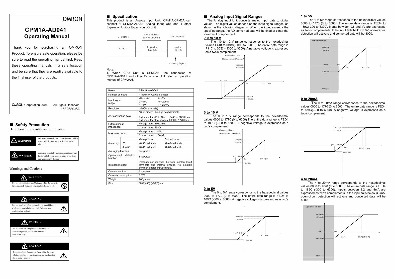
CPM1A-AD041 Operating Manual
Thank you for purchasing an OMRON
Product. To ensure safe operation, please be
sure to read the operating manual first. Keep
these operating manuals in a safe location
and be sure that they are readily available to
the final user of the products.
OMRON Corporation 2004 All Rights Reserved 1632680-6A
The 1 to 5V range corresponds to the hexadecimal values 0000 to 1770 (0 to 6000). The entire data range is FED4 to 189C(-300 to 6300). Inputs between 0.8 and 1V are expressed as two’s complements. If the input falls bellow 0.8V, open-circuit detection will activate and converted data will be 8000.
The Analog Input Unit converts analog input data to digital values. The digital values depend on the input signal ranges, as shown in the following diagrams. When the input exceeds the specified range, the AD converted data will be fixed at either the lower limit or upper limit.
This product is log Input Unit. CPM1A/CPM2A can connect 1 CP 1 Analog Input Unit and 1 other Expansion Unit ion I/O Unit.
CPU UniExpansionI/O Unit
AnalogI/O Unit
CPM1A/CPCPM1A-20EDR 1
PM 1A-20EDT CPM1A-AD041 -10 to 10 V
0.8V
5V 5.2V
FED4(-300)
1770(6000)
189C(6300)
Open circuit detection
1V
0000(0)
The -10 to 10 V range corresponds to the hexadecimal values F448 to 0BB8(-3000 to 3000). The entire data range is F31C to 0CE4(-3300 to 3300). A negative voltage is expressed as a two’s complement. Converted D ata
Hexadecimal(Decimal)
Safety Precaution Definition of Precautionary Information
Indicates a potentially hazardous situation , which if not avoided, could result in death or serious injury.
WARNING
Indicates a potentially hazardous situation, which if not avoided, could result in minor or moderate injury, or property damage.
WARNING
Warnings and Cautions
Dot not attempt to take any Unit apart while the power is being supplied. Doing so may result in electric shock.
WARNING
WARNING
Dot not touch any of the terminals or terminal blocks while the power is being supplied. Doing so may result in electric shock.
Dot not touch the components in any occation in order to prevent any malfunction due to static electricity.
CAUTION
CAUTION
Dot not touch the Connecting Cable while the power is being supplied in order to prevent any malfunction due to static electricity.
4 Analog Inputs
-11V -10V 0000(0)
0BB8(3000)
0CE4(3300)
Note: 1. When CPU Unit is CPM2AH, the connection of CPM1A-AD041 and other Expansion Unit refer to operation manual of CPM2AH.
Items Number of inputs
Input signal range
Resolution
A/D conversion d
External input impedance
Max. rated input
25Accuracy0 to
Averaging functioOpen-circuit defunction
Isolation method
Conversion time Current consumpWeight Size
ation an Ana
M1A-AD04or Expans
C 4
-011
ata 1
FFVCVCV
±55 ±n Stection S
Ptb2
tion 328
or C
t
M2A
8000(open)
0V 10V 11V
F31C(-3300) F448(-3000)
PM1A-AD041 inputs (4 words allocated) 10~10V 0~5V ~10V 0~20mA ~5V 4~20mA /6000(full scale) 6-bit binary (4-digit hexadecimal)
ull scale for -10 to 10V: F448 to 0BB8 Hex ull scale for other ranges: 0000 to 1770 Hex oltage input: 1MΩ min urrent input: 250Ω oltage input: ±15V urrent input: ±30mA oltage Input Current Input 0.3% full scale ±0.4% full scale 0.6% full scale ±0.8% full scale upported
upported
hotocoupler isolation between analog Input erminals and internal circuits. No isolation etween analog Input signals. ms/point .0W
00g max 6(W)×50(H)×90(D)mm
0 to 20mA The 0 to 20mA range corresponds to the hexadecimal values 0000 to 1770 (0 to 6000). The entire data range is FED4 to 189C(-300 to 6300). A negative voltage is expressed as a two’s complement.
0 to 10 V The 0 to 10V range corresponds to the hexadecimal
values 0000 to 1770 (0 to 6000).The entire data range is FED4 to 189C (-300 to 6300). A negative voltage is expressed as a two’s complement.
Converted
(-1mA) 0mA
1770(6000) 189C(6300)
FED4(-300)
(20mA) (21mA) 0000(0)
Data Hexadecimal (Decimal)
-0.5V 0V 10V 10.5V
1770(6000) 189C(6300)
FED4(-300)
0000(0)
4 to 20mA The 4 to 20mA range corresponds to the hexadecimal
values 0000 to 1770 (0 to 6000). The entire data range is FED4 to 189C (-300 to 6300). Inputs between 3.2 and 4mA are expressed as two’s complements. If the input falls below 3.2mA, open-circuit detection will activate and converted data will be 8000.
0 to 5V The 0 to 5V range corresponds to the hexadecimal values
0000 to 1770 (0 to 6000). The entire data range is FED4 to 189C (-300 to 6300). A negative voltage is expressed as a two’s complement.
(3.2mA)
FED4(-300)
1770(6000) 189C(6300)
Open circuit detection
8000(open)
(20mA) (20.8mA)(4mA)
0000(0)
-0.25V 0V 5V 5.25V
1770(6000) 189C(6300)
FED4(-300)
0000(0)
Averaging Function for Analog Inputs The averaging function can be enabled for inputs with
setting the input range. The averaging function stores the average(a moving average) of the last eight input values as the converted value. Use this function to smooth inputs that vary at a short interval.
Open-circuit Detection Function for Analog Inputs
The open-circuit detection function is activated when the input range is set to 1to 5V and the voltage drops below 0.8V, or when the input range is set to 4 to 20mA and the current drops below 3.2mA. When the open-circuit detection function is activated, the converted data will be set to 8000. The open-circuit detection function is enabled or cleared when data is converted. If the input returns to the convertible range, the open-circuit detection is cleared automatically. Using Analog Input Unit Connect the Analog Input Unit.
Analog inputs: 0 to5V, 1 to 5V, 0 to 10V, -10 to 10V,
0 to 20mAm, 4 to 20mA Set inputs as voltage or analog
and set the averaging function .
Connect analog Input devices
Write the range code. Analog inputs: Read converted data
Analog Inputs
Ladder program
MOV instructionMOV(21)
Write the rangecode. Reads the
converted values.
Word(n+1)
Word(n+2)
Word(m+1)
Word(m+2)
Word(m+3)
Word(m+4)
Range code
Analog input 1converted value
Analog input 2converted valueAnalog input 3converted value
Analog input 4converted value
CPU Unit Analog Input Unit
Where ‘m’is the last input word and ‘n’isthe last output word allocated to the CPU Unit,or previous Expansion Unit or Expansion I/O Unit
Analog devicesTemperature sensor
Pressure sensor Speed sensor Voltage/current meter Other
I/O Allocation
I/O is allocated for the Analog Input Unit in the same way as other Expansion Units or Expansion I/O Units starting from the next word following the last allocated word on the CPU Unit or previous Expansion Unit or Expansion I/O Unit. When “m” is the last allocated input word and “n” the last allocated output word on the CPU Unit, or previous Expansion Unit or Expansion I/O Unit, the allocation will be as follows:
Analog input 1: Word m+1Analog input 2: Word m+2Analog input 3: Word m+3Analog input 4: Word m+4
CPM1A-AD041Analog Input Unit
Analog Input ranges setting:Word n+1Word n+2
For example, in the following diagram an Analog Input Unit is connected to a CPU Unit with 30 I/O points.
30-pointCPU Unit
CPM1A-AD041Analog Input Unit
Inputs
Outputs
IR000IR001
IR002IR003
IR010IR011
IR004IR005
IR012IR013
Setting Input Signal Range
Input signal ranges are set by writing a range code to the output word of the Analog Input Unit. The range code must be set for the Analog Input Unit to convert data. The range code settings provide the combinations of signal ranges for the analog inputs, as shown in the following table.
Voltage/current selections for the CPM1A-AD041 are made by connecting the appropriate terminals.
Write the range codes to the Analog Input Unit’s output word (n+1, n+2) in the first cycle of program execution.
ch settingn+1 AD input 1,input 2 range setting
n+2 AD input 3,input 4 range settingAD input setting details:
3 2 1 0
Setting code
AD input allowed 1:open 0:closed
Averaging function 1:used 0:not used
00:-10V~+10V 01:0~10V 10:1~5V(4~20mA) 11:0~5V( 0~20mA)
Note: Be sure to write the correct terminals. “n” is the last output word allocated to the CPU Unit, or
previous Expansion Unit or Expansion I/O Unit.
1 0 0 0 0 0 0 0
Analog input 2 Analog input 1
n+1
15 8 7 6 5 4 3 2 1 0
0 0 0
Analog input 4 Analog input 3
15 8 7 6 5 4 3 2 1 0
Note: 1. The Analog Input Unit will not start converting analog
input values until the range code has been written. Until conversion starts, inputs will be 0000.
2. Once the range code has been set , it is not possible to change the setting while power is being supplied
t. To change the input range, turn the then ON again.
Wiring Analog Input Devices CPM1A-AD041 Terminal Arrangements
V IN3
V IN3V IN1 COM1 I IN2V IN2I IN1 COM2
INCOM2V IN2I IN1
COM1V IN1 I IN2
CH
COM4COM3 I IN4
I IN3 V IN4NC
AG
AGCOM4V IN4I IN3I IN4COM3 NC
Label SignalV IN1 Voltage input 1 I IN1 Current input 1 COM1 Input common 1 V IN2 Voltage input 2 I IN2 Current input 2 COM2 Input common 2 V IN3 Voltage input 3 I IN3 Current input 3 COM3 Input common 3 V IN4 Voltage input 4 I IN4 Current input 4 COM4 Input common 4
Note: For current inputs, short VIN1 to I IN1, VIN2 to I IN2, VIN3to I IN3 and VIN4to I IN4. Wiring for Analog Inputs Note: 1. Use shielded twisted-pair cables, but do not connect
the shield. 2. When an input is not being used, short the V IN and
COM terminals. 3. Separate wiring from power lines (AC power supply
lines, high-voltage lines, etc.) 4. When there is noise in the power supply line, Install a
noise filter on the input section and the Power Supply Unit.
5. Turn ON the power supply for the CPU Unit first, and then turn ON the power supply for the load after confirming correct operation.
Ladder Program Specifying the Range Code
Specify the I/O signal range by writing the range code to the Analog Input Unit’s output word from the ladder program in the first cycle of program execution. The Analog Input Unit will start to convert analog Input values once the range code has been specified. Write the range code to the Analog Input Unit’s output word in the first cycle of operation; the Analog Input Unit’s output word is “n+1”and “n+2” when “n” is the last word allocated to the CPU Unit, or previous Expansion Unit or Expansion I/O Unit in the configuration.
Reading Converted Analog Input Values The ladder program can be used to read the memory area
where the converted values are stored. Values are output to the next four words (m+1, m+2,m+3,m+4) following the last input word (m) allocated to the CPU Unit or previous Expansion Unit or Expansion I/O Unit. Note: After the range code has been written, if no analog signals input, the output values will be 0000 if the range is 0 to 10 V, –10 to 10 V, 0 to 5 V or 0 to 20 mA, or it will be 8000 if the range is1 to 5 V or 4 to 20 mA. Programming Example This programming example uses the following ranges:
Analog Input 1: 0~10V no Averaging function Analog Input 2: 4~20mA no Averaging function Analog Input 3: no use Analog Input 4: -10~10V Averaging function
be used The system is: CPM1A-30CDR-V1+CPM1A-AD041 First_Cycle(25315)P_
MOV(21)
#80A9
12
MOV(21)
#80C0
13
TIM001Executioncondition
TIM001Executioncondition
TIM001Executioncondition
MOV(21)
2
DM0
MOV(21)
3
DM1
MOV(21)
5
CMP(20)
3
#8000
TIM001Executioncondition
25506(=)10.00
P_ON(25313)
TIM
001
#0005
Write the range code80A9 to the Unit
Write the range code80C0 to the Unit
Open-circuit alarm
Read the Analog input1'sconverted value
Read the Analog input2'sconverted value
Read the Analog input4'sconverted value
COM
_ Voltage Input
+
+
_
250E
510K
0V
V IN
I IN
COM
250E
510K
0V
I INCurrent Input
V IN
CPM1A-AD041 Shield line
Program operation inthe ladder program.
Wire the analog Input
Set the input ranges.
Connect the Unit.
3.
0 0 0
Wherangethe V
0
1n+2n an input is not being used, to set OFF the code orresponds the input, and short IN an erminals.
6. Turn OFF the power supply for the load before turning OFF the power supply for the CPU Unit.
DM2
which cd COM tCPU Uninit OFF
the PU U
toC
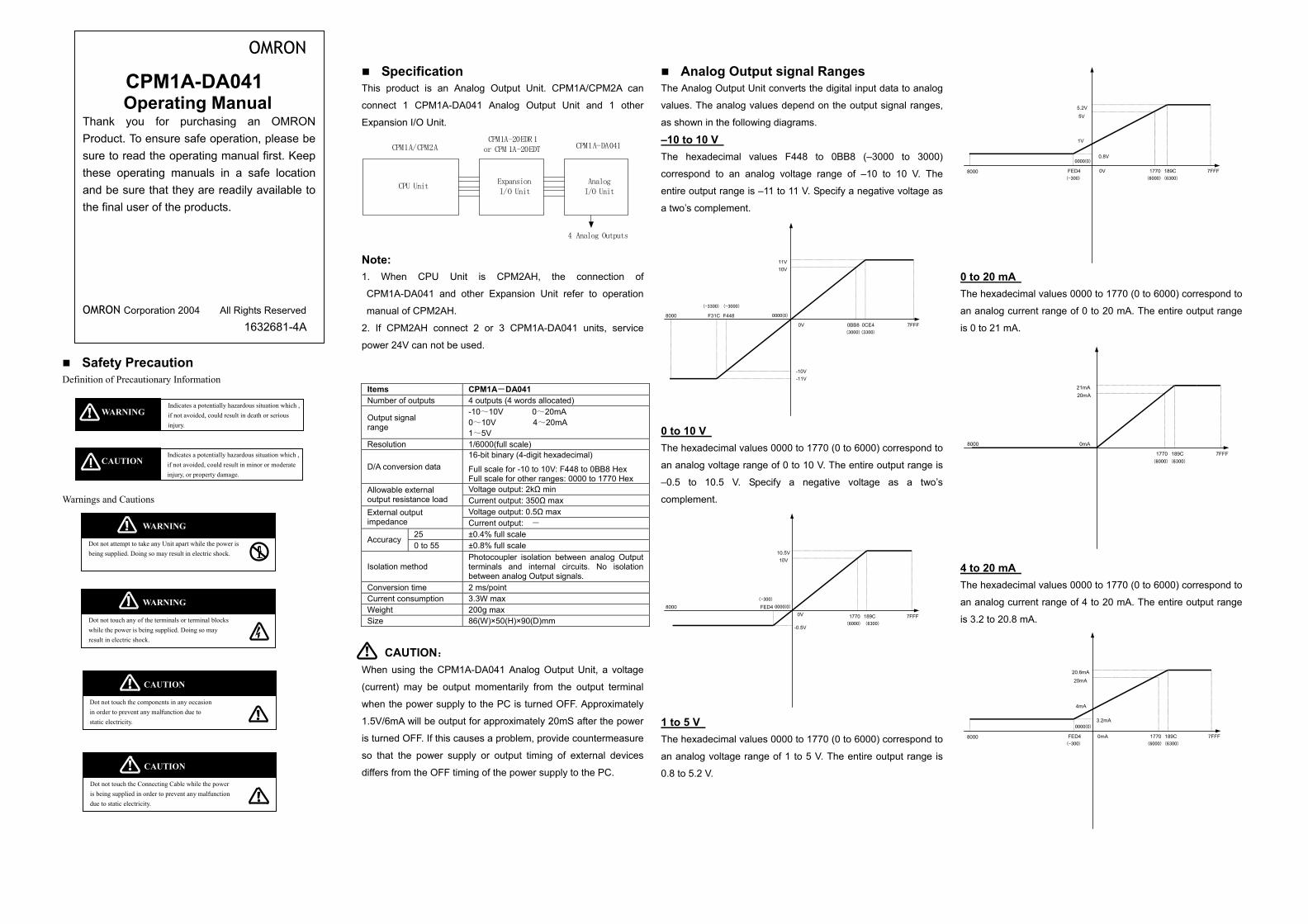
CPM1A-DA041 Operating Manual
Thank you for purchasing an OMRONProduct. To ensure safe operation, please besure to read the operating manual first. Keepthese operating manuals in a safe locationand be sure that they are readily available tothe final user of the products.
OMRON Corporation 2004 All Rights Reserved 1632681-4A
OMRON Specification Analog Output signal Ranges
0V
0.8V
5V
5.2V
1770 189C 7FFFFED48000
1V
(6300)(6000)(-300)
0000(0)
product is an Analog Output Unit. CPM1A/CPM2A can
nect 1 CPM1A-DA041 Analog Output Unit and 1 other
ansion I/O Unit.
The Analog Output Unit converts the digital input data to analog
values. The analog values depend on the output signal ranges,
as shown in the following diagrams.
–10 to 10 V
CPM1A/CPM2ACPM1A-20EDR 1
or CPM 1A-20EDT CPM1A-DA041
The hexadecimal values F448 to 0BB8 (–3000 to 3000)
correspond to an analog voltage range of –10 to 10 V. The Safety Precaution
Definition of Precautionary Information
Warnings and Cautions
WARNING Dot not touch any of the terminals or terminal blocks while the power is being supplied. Doing so may result in electric shock.
Indicates a potentially hazardous situation which , if not avoided, could result in death or serious injury.
WARNING
Indicates a potentially hazardous situation which , if not avoided, could result in minor or moderate injury, or property damage.
CAUTION
WARNING Dot not attempt to take any Unit apart while the power is being supplied. Doing so may result in electric shock.
CAUTION Dot not touch the components in any occasion in order to prevent any malfunction due to static electricity.
CAUTION Dot not touch the Connecting Cable while the power is being supplied in order to prevent any malfunction due to static electricity.
This
con
Exp
CPU UnitExpanI/O
AnalogI/O Unit
4 Analog Outputs
Note:
entire output range is –11 to 11 V. Specify a negative voltage as
a two’s complement.
1. When CPU Uni CPM the connection of
CPM1A-DA041 and o xpan Unit refer to operation
manual of CPM2AH.
10V11V
0 to 20 mA The hexadecimal values 0000 to 1770 (0 to 6000) correspond to
2. If CPM2AH connect 2 or 3 C
power 24V can not be used.
CAUTION:
Items CPM1A-DANumber of outputs 4 outputs (4
Output signal range
-10~10V 0~10V 1~5V
Resolution 1/6000(full s
D/A conversion data 16-bit binary
Full scale forFull scale forVoltage outpAllowable external
output resistance load Current outpVoltage outpExternal output
impedance Current outp25 ±0.4% full scAccuracy0 to 55 ±0.8% full sc
Isolation method Photocoupleterminals abetween ana
Conversion time 2 ms/point Current consumption 3.3W max Weight 200g max Size 86(W)×50(H
When using the CPM1A-DA041 A
(current) may be output momenta
when the power supply to the PC
1.5V/6mA will be output for approx
is turned OFF. If this causes a prob
so that the power supply or outp
differs from the OFF timing of the p
sionUnit
2AH,
sion
t is
ther E
-11V
0V
-10V
0BB8
(-3300) (-3000)
(3000) (3300)
0CE4
F31C F4488000
7
0000(0)
PM1A-DA041 units, service
041 words allocated) 0~20mA 4~20mA
cale) (4-digit hexadecimal)
-10 to 10V: F448 to 0BB8 Hex other ranges: 0000 to 1770 Hex ut: 2kΩ min ut: 350Ω max ut: 0.5Ω max ut: -
aleale r isolation between analog Output nd internal circuits. No isolation log Output signals.
)×90(D)mm
0 to 10 V The hexadecimal values 0000 to 1770 (0 to 6000) corres
an analog voltage range of 0 to 10 V. The entire output r
–0.5 to 10.5 V. Specify a negative voltage as a
complement.
0V
-0.5V
10V10.5V
1770 7
FED48000
189C(6000) (6300)
(-300)
0000(0)
nalog Output Unit, a voltage
rily from the output terminal
is turned OFF. Approximately
imately 20mS after the power
lem, provide countermeasure
ut timing of external devices
ower supply to the PC.
1 to 5 V The hexadecimal values 0000 to 1770 (0 to 6000) corres
an analog voltage range of 1 to 5 V. The entire output r
0.8 to 5.2 V.
FFF
an analog current range of 0 to 20 mA. The entire output range
is 0 to 21 mA.
20mA21mA
1770 189C 7FFF
8000 0mA
(6300)(6000)
pond to
ange is
two’s
FFF
4 to 20 mA The hexadecimal values 0000 to 1770 (0 to 6000) correspond to
an analog current range of 4 to 20 mA. The entire output range
is 3.2 to 20.8 mA.
0mA
3.2mA
20mA
20.8mA
1770 189C 7FFFFED48000
4mA
(6300)(6000)(-300)
0000(0)
pond to
ange is
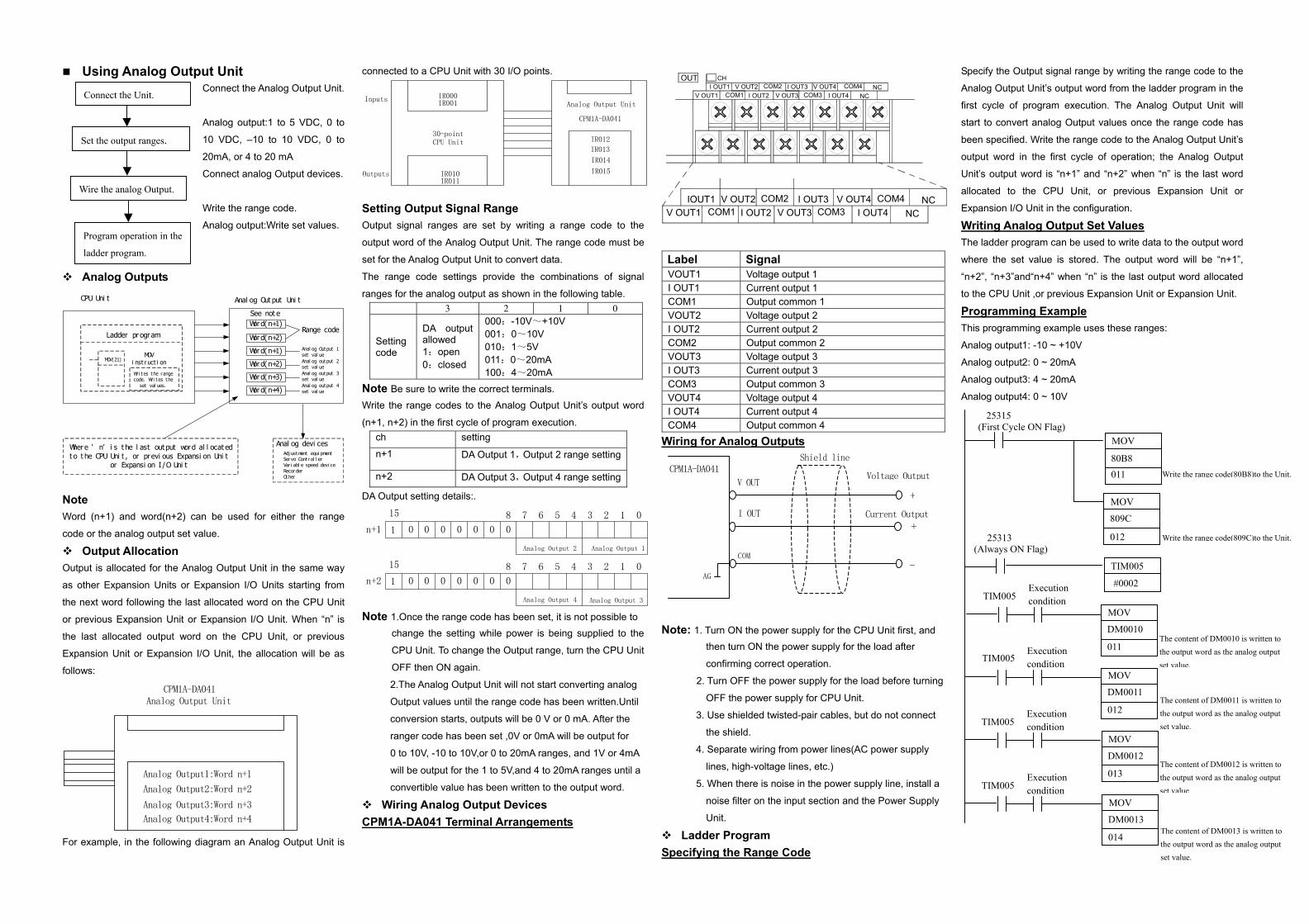
Using Analog Output Unit Connect the Analog Output Unit.
Analog output:1 to 5 VDC, 0 to
10 VDC, –10 to 10 VDC, 0 to
20mA, or 4 to 20 mA
Connect analog Output devices.
Write the range code.
Analog output:Write set values.
Analog Outputs
Ladder pr ogram
MOVi nst r uct i onMOV(21)
Wr i t es t he rangecode. Wr i t es t he
set val ues.
Word(n+1)
Word(n+2)
Word(n+1)
Word(n+2)
Word(n+3)
Word(n+4)
Anal og Out put 1set val ueAnal og out put 2set val ueAnal og out put 3set val ueAnal og out put 4set val ue
CPU Uni t Anal og Out put Uni t
Wher e ‘ n’ i s t he l ast out put word al l ocat edt o t he CPU Uni t , or previ ous Expansi on Uni t
or Expansi on I /O Uni t
Anal og devi cesAdj ust ment equi pmentServo Cont r ol l erVar i abl e speed devi ceRecorderOt her
See not e
Range code
Note Word (n+1) and word(n+2) can be used for either the range
code or the analog output set value. Output Allocation
Output is allocated for the Analog Output Unit in the same way
as other Expansion Units or Expansion I/O Units starting from
the next word following the last allocated word on the CPU Unit
or previous Expansion Unit or Expansion I/O Unit. When “n” is
the last allocated output word on the CPU Unit, or previous
Expansion Unit or Expansion I/O Unit, the allocation will be as
follows: CPM1A-DA041
Analog Output Unit
Analog Output1:Word n+1
Analog Output2:Word n+2
Analog Output3:Word n+3
Analog Output4:Word n+4
For example, in the following diagram an Analog Output Unit is
connected to a CPU Unit with 30 I/O points.
Setting Output Signal Range Output signal ranges are set by writing a range code to the
output word of the Analog Output Unit. The range code must be
set for the Analog Output Unit to convert data.
The range code settings provide the combinations of signal
ranges for the analog output as shown in the following table. 3 2 1 0
Setting code
DA output allowed 1:open 0:closed
000:-10V~+10V 001:0~10V 010:1~5V 011:0~20mA 100:4~20mA
Note Be sure to write the correct terminals. Write the range codes to the Analog Output Unit’s output word
(n+1, n+2) in the first cycle of program execution. ch setting
n+1 DA Output 1,Output 2 range setting
n+2 DA Output 3,Output 4 range setting
DA Output setting details:.
1 0 0 0 0 0 0 0
Analog Output 2 Analog Output 1
n+1
15 8 7 6 5 4 3 2 1 0
1 0 0 0 0 0 0 0
Analog Output 4 Analog Output 3
n+2
15 8 7 6 5 4 3 2 1 0
Note 1.Once the range code has been set, it is not possible to change the setting while power is being supplied to the
CPU Unit. To change the Output range, turn the CPU Unit
OFF then ON again.
2.The Analog Output Unit will not start converting analog
Output values until the range code has been written.Until
conversion starts, outputs will be 0 V or 0 mA. After the
ranger code has been set ,0V or 0mA will be output for
0 to 10V, -10 to 10V,or 0 to 20mA ranges, and 1V or 4mA
will be output for the 1 to 5V,and 4 to 20mA ranges until a
convertible value has been written to the output word.
Wiring Analog Output Devices CPM1A-DA041 Terminal Arrangements
V OUT3
V OUT3V OUT1 I OUT2COM1V OUT2IOUT1 COM2
OUTV OUT2 COM2I OUT1
COM1V OUT1 I OUT2
CH
COM4I OUT4COM3
I OUT3 V OUT4NC
NC
NCV OUT4 COM4I OUT3I OUT4COM3 NC
Label SignalVOUT1 Voltage output 1I OUT1 Current output 1 COM1 Output common 1 VOUT2 Voltage output 2I OUT2 Current output 2 COM2 Output common 2 VOUT3 Voltage output 3I OUT3 Current output 3 COM3 Output common 3 VOUT4 Voltage output 4I OUT4 Current output 4 COM4 Output common 4
Wiring for Analog Outputs Note: 1. Turn ON the power supply for the CPU Unit first, and
then turn ON the power supply for the load after
confirming correct operation. 2. Turn OFF the power supply for the load before turnin
OFF the power supply for CPU Unit. 3. Use shielded twisted-pair cables, but do not connect
the shield.
4. Separate wiring from power lines(AC power supply
lines, high-voltage lines, etc.)
5. When there is noise in the power supply line, install a
noise filter on the input section and the Power Supply
Unit.
Ladder Program Specifying the Range Code
AG
CPM1A-DA041
Current Output
Voltage Output
I OUT
COM
V OUT
+
+
-
Shield line
Analog Output Unit
CPM1A-DA041
IR014
IR015
IR012
IR013
30-pointCPU Unit
IR010IR011
IR000IR001
Outputs
Inputs
Program operation in the
ladder program.
Wire the analog Output.
Set the output ranges.
Connect the Unit.
g
Specify the Output signal range by writing the range code to the
Analog Output Unit’s output word from the ladder program in the
first cycle of program execution. The Analog Output Unit will
start to convert analog Output values once the range code has
been specified. Write the range code to the Analog Output Unit’s
output word in the first cycle of operation; the Analog Output
Unit’s output word is “n+1” and “n+2” when “n” is the last word
allocated to the CPU Unit, or previous Expansion Unit or
Expansion I/O Unit in the configuration. Writing Analog Output Set Values The ladder program can be used to write data to the output word
where the set value is stored. The output word will be “n+1”,
“n+2”, “n+3”and“n+4” when “n” is the last output word allocated
to the CPU Unit ,or previous Expansion Unit or Expansion Unit.
Programming Example This programming example uses these ranges:
Analog output1: -10 ~ +10V
Analog output2: 0 ~ 20mA
Analog output3: 4 ~ 20mA
Analog output4: 0 ~ 10V
Execution condition TIM005
DM0012
013The content of DM0012 is written to the output word as the analog output set value.
The content of DM0013 is written to the output word as the analog output set value.
Execution condition TIM005
014
DM0013
MOV
MOV
Execution condition TIM005
012
DM0011
MOV
(Al s ON Flag) way25313
011
MOV
DM0010
TIM005 Execution condition
TIM005
#0002
25315 (First Cycle ON Flag)
011 80B8
MOV
012
809C
MOV
Write the range code(80B8)to the Unit.
Write the range code(809C)to the Unit.
The content of DM0011 is written to the output word as the analog output set value.
The content of DM0010 is written to the output word as the analog output set value.