on going activities of the ru 8 on the performance ... · pdf fileducted by the sap2000...
TRANSCRIPT

Materiali ed Approcci Innovativi per il Progetto in Zona Sismica e la Mitigazione della Vulnerabilità delle Strutture
Università degli Studi di Salerno – Consorzio ReLUIS, 12-13 Febbraio 2007
On going activities of the RU 8 on the performance evaluation of steel-concrete composite joints and of steel connection details for fatigue performance of
composite bridge decks
A. Bonelli1, O. S. Bursi1, F. Ferrario1, R. Pucinotti2, N. Tondini1, R. Zandonini1
ABSTRACT: This paper deals with the behaviour of steel-concrete composite joints and details of steel-concrete composite bridges. In the first part of the paper, a multi-objective advanced design methodology of composite joints with column systems composed of concrete filled steel tubes subjected to earthquake and fire loadings is considered. A series of experimental tests are going to be carried out at the Laboratory for Materials and Structures of the University of Trento to demonstrate the adequacy of the proposed joint design. The details of the joints are here presented. Whilst the second part reports the results of an effort devoted to the identification of novel design solutions for the most critical details in steel-concrete bridges in order to improve both the high-and low-cycle fatigue strength. In particular, two steel-concrete composite bridges, the Montevideo box-girder viaduct and the Rocchetta truss bridge, are under study since: i) they are a recurrent structural typology for composite bridges; ii) they are not seismically designed. The identification of the critical details from a dynamic point of view by means of Finite Element models is here presented.
1 STEEL-CONCRETE COMPOSITE JOINTS
1.1 Introduction
In the design of steel-concrete composite buildings the seismic safety and the fire safety are considered separately and the sequence of seismic and fire loadings are not taken into account. In reality, the risk of loss of lives increases if a fire occurs within the building after an earthquake. It is obvious therefore, that fire after earthquake is a de-sign scenario that should be properly addressed in any performance-based design in locations where significant earthquakes can occur. A new approach is proposed in this research in order to pursue a multi-objective design criterion instead of a traditional sin-gle-objective design where fire safety and seismic safety are achieved independently. This approach takes into account seismic safety and fire safety with regard to acciden-tal actions as well as fire safety on a structure characterised by stiffness deterioration and strength degradation owing to seismic actions. As a result, the fire design applied to a structure with reduced capacity owing to seismic actions will achieve structural, seismic and fire safety as required; but also structural and fire safety and structural and seismic safety will be guaranteed, respectively. The research activity presented here is mainly concerned with the final design of the proposed bolted beam-to-column joints together with the definition of some structural details for the composite beams, such as
1 Dipartimento di Ingegneria Meccanica e Strutturale, Università di Trento, Trento, Italia 2 Dipartimento di Meccanica e Materiali, Università Mediterranea di Reggio Calabria, Reggio C., Italia

Materiali ed Approcci Innovativi per il Progetto in Zona Sismica e la Mitigazione della Vulnerabilità delle Strutture
Università degli Studi di Salerno – Consorzio ReLUIS, 12-13 Febbraio 2007
the lay-out of structural steel reinforcements inside the slab and the definition of some details for the steel connection and stud connectors around the column. Structural and thermal analyses were performed in order to assess the global behaviour under different load combinations and to obtain the internal temperature distribution. The results of both thermal and mechanical numerical analyses will be calibrated on the basis of the experimental results in order to derive additional information about the behaviour of the proposed joint. Moreover, the FE model used for the design will be de-scribed. 1.2 Composite Buildings
In order to obtain the values of the actions used in the design of the proposed joints, two moment resisting frames having the same structural typology but different slab sys-tems were analysed: a composite steel-concrete slab with structural profiled steel sheeting and a concrete slab composed of electro-welded lattice girders. The composite steel-concrete office-building had 5 floors with 3.5 m storey height. It was made up by three moment resisting frames placed at the distance of 7.5 m each in the longitudinal direction, while it was braced in the transverse direction. Taking into ac-count the different load bearing capacities of the two slab systems as well as the need to avoid propping systems during the construction phase, a different distance between the secondary beams was adopted for the two solutions. As a result, the main moment resisting frame is made up by two bays spanning 7.5 m and 10.0 m in the solution with steel sheeting with a distance between secondary beams equal to 2.5 m; and by two bays spanning 7.0 m and 10.5 m in the solution with lattice steel girders with a distance between secondary beams equal to 3.5 m. The rele-vant plans are depicted in Figure 1a and 1b, respectively.
a) b)
Figure 1. Plain and Structure typology a) slab with prefabricate lattice girder, b) slab with profiled steel sheet-
ing.
All slabs were arranged in the direction parallel to the main frames. The main beams were IPE 400 while the secondary ones were IPE 300. The columns were concrete-filled column with a CFT filled tubular column steel profile with a diameter of 457 mm and a thickness of 12 mm. Thermal analyses of cross sections were performed in order to ob-tain the internal temperature distribution and afterwards structural analyses were per-formed on the whole frames to assess the global behaviour under the combined action of vertical and fire loadings. In detail, structural analyses were performed on two-dimensional frames considering the worst fire design scenario. Moreover, a 3D finite model of the interior joint was implemented in the Abaqus 6.4.1 code (Hibbitt et al. 2000). With reference to seismic analysis, a modal response spectrum analysis was con-
2,52,52,52,52,52,52,5
17,5
10se
cond
ary
beam
7,5se
cond
ary
beam
15
7,5
7,5
main beammain beam
main moment resisting frame
seco
ndar
ybe
am
7,5
15
3,5 3,53,53,5
main beam
3,5
main beam
7,5
7
17,510,5
seco
ndar
ybe
am
main moment resisting frame

Materiali ed Approcci Innovativi per il Progetto in Zona Sismica e la Mitigazione della Vulnerabilità delle Strutture
Università degli Studi di Salerno – Consorzio ReLUIS, 12-13 Febbraio 2007
ducted by the SAP2000 program (Wilson and Habibullah 1988) to estimate seismic ac-tions, while a finite element modelling by the Abaqus 6.4.1code was employed to simu-late beam-to-column joints and to estimate the effective width of the main horizontal plates of the joints. Moreover, the Abaqus 6.4.1 code was employed to conduct the thermal analysis of the joint for different times of fire exposition, 30 min and 60 min, re-spectively; while thermal analyses with different fire scenarios were carried out by the SAFIR (Franssen 2000) code on a two-dimensional frame model. Figure 2 shows the con-siderable reduction of the design capacity moment of the joint as a function of the time of fire exposition. In detail, the hogging capacity moment becomes approximately the 20% of the initial value after 30 minutes of exposition, while it approaches about to 5% of the initial value after 60 minutes. Nevertheless, this time is enough to quit the build-ing after a severe earthquake. The joint endowed with prefabricated slab exhibits a better live behaviour compared to the joint endowed with steel sheeting (see Fig. 3). In fact, the steel portion of the column heats the concrete slab near the joint and the steel elements show elevated temperatures even for short times of fire exposition.
Hogging Moment Resistant of Joint
0
200
400
600
800
1000
0 0.5 1 1.5 2 2.5 3 3.5 4[mrad]
M[k
Nm
]
T=20°C 30' of exposition 60' of exposition
Figure 2. Moment-rotation relationship of the beam-to-
column joint as a function of the time of fire exposition. Figure 3. Abaqus: fire FE modelling.
1.3 Composite beams
Two different types of composite beams were checked according to point 6.1.1 of Eurocode 4 (prEN 1994-1-1 2004). In the first one, the beam section was an IPE400 with steel grade S355 while the deck was a composite slab with a prefabricated lattice girder made by the Pittini Group. In this case, the slab reinforcement was performed by 3+3φ12 longitudinal steel bars and by 5+5φ12@100 mm plus 8+8φ16@200 mm transversal steel bars. A mesh φ6@200x200 mm completes the slab reinforcement. In the second type, the same beam section was adopted and a composite slab with profiled steel sheeting was made following the rules given in Section 9 of Eurocode 4 (prEN 1994-1-1 2004). The slab reinforcement consisted of 3+3φ12 longitudinal steel bars and of 4+4φ12@100 mm and 7+7φ16@250 mm transversal steel bars. Moreover, the same mesh φ6@200x200 mm was adopted. The concrete class was C30/37 while the steel grade S450 was adopted for the reinforcing steel bars. 1.4 Composite columns
Composite columns (steel grade S355) were realized with concrete-filled circular hollow sections all having an external wall 457 mm wide and 12 mm thick. The column reinforcement consisted of 8φ16 longitudinal steel bars and stirrups φ8@150 mm. The concrete class of composite columns was C30/37, while the steel grade S450 was adopted for the reinforcing steel bars. 1.5 Beam-to-column composite joint
A total of 4 specimens was designed and fabricated according to Eurocode 4 (prEN 1994-1-1 2004, prEN 1994-1-2 2003) and Eurocode 8 (prEN 1998-1 2003) provisions.
Materiali ed Approcci Innovativi per il Progetto in Zona Sismica e la Mitigazione della Vulnerabilità delle Strutture
Università degli Studi di Salerno – Consorzio ReLUIS, 12-13 Febbraio 2007
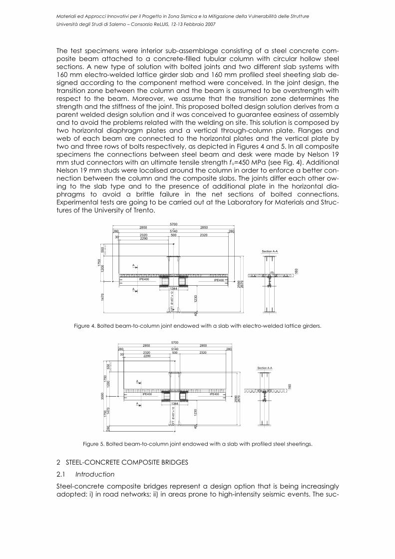
The test specimens were interior sub-assemblage consisting of a steel concrete com-posite beam attached to a concrete-filled tubular column with circular hollow steel sections. A new type of solution with bolted joints and two different slab systems with 160 mm electro-welded lattice girder slab and 160 mm profiled steel sheeting slab de-signed according to the component method were conceived. In the joint design, the transition zone between the column and the beam is assumed to be overstrength with respect to the beam. Moreover, we assume that the transition zone determines the strength and the stiffness of the joint. This proposed bolted design solution derives from a parent welded design solution and it was conceived to guarantee easiness of assembly and to avoid the problems related with the welding on site. This solution is composed by two horizontal diaphragm plates and a vertical through-column plate. Flanges and web of each beam are connected to the horizontal plates and the vertical plate by two and three rows of bolts respectively, as depicted in Figures 4 and 5. In all composite specimens the connections between steel beam and desk were made by Nelson 19 mm stud connectors with an ultimate tensile strength fu=450 MPa (see Fig. 4). Additional Nelson 19 mm studs were localised around the column in order to enforce a better con-nection between the column and the composite slabs. The joints differ each other ow-ing to the slab type and to the presence of additional plate in the horizontal dia-phragms to avoid a brittle failure in the net sections of bolted connections. Experimental tests are going to be carried out at the Laboratory for Materials and Struc-tures of the University of Trento.
A
A
Section A-A
meshHD 620
285028505700
30 229023205002320
2805140280
4012
30
2670
2590
1470
(310
+24
1.3
)55
012
001750
CFT
Ø45
7x
12
1344
IPE400IPE400
160
Figure 4. Bolted beam-to-column joint endowed with a slab with electro-welded lattice girders.
1750
1750
1200
550
(310
+24
1.3
)14
7028
0
2590
2670
1230
40
280 5140 2802320 500 2320229030
57002850 2850
Section A-A
A
A
160
CFT
Ø45
7x
12
IPE400 IPE400
1344
Figure 5. Bolted beam-to-column joint endowed with a slab with profiled steel sheetings.
2 STEEL-CONCRETE COMPOSITE BRIDGES
2.1 Introduction
Steel-concrete composite bridges represent a design option that is being increasingly adopted: i) in road networks; ii) in areas prone to high-intensity seismic events. The suc-

Materiali ed Approcci Innovativi per il Progetto in Zona Sismica e la Mitigazione della Vulnerabilità delle Strutture
Università degli Studi di Salerno – Consorzio ReLUIS, 12-13 Febbraio 2007
cess of this design solution is due both to the advantages that composite elements offer in terms of stiffness, resistance and ductility and to the speed and ease of their erection. In detail, steel-concrete composite bridges represent a competitive design option, both due to the structural effectiveness and costs, for midspans ranging between 50 and 150 m. Numerous advantages can be mentioned but several issues still remain open. A pe-culiar issue is the lack of an accurate knowledge about dynamic effects, in particular in end-diaphragms and bearing regions which result to be very sensitive parts owing to stress concentrations. Moreover, they can be widely damaged when subjected to strong dynamic loadings, like earthquakes; in addition, dynamic effects induce vibra-tions owing to traffic loads, which can amplify fatigue phenomena. This part of the paper is organised as follows. Initially, the work developed on the Mon-tevideo viaduct will be presented: i) description of the structure; ii) features of FE model; iii) results of the seismic analysis and identification of the critical details. Analogously, the second case study, the Rocchetta bridge, will be shown in the same way. 2.2 Montevideo viaduct
2.2.1 Description of the structure
The Montevideo viaduct is a steel-concrete box-girder bridge, built in the eighties, with 7 spans, 75 m each. It is a simply supported bridge with 4 curved spans which have dif-ferent curvature radius: going along the bridge from Trento to Cadine the first three spans have R=350 m, while the 7th and last span has approximately R=200 m. The al-timetric view of the viaduct is shown in Figure 6. The transversal section (Fig. 7) consists of 4 lanes corresponding to 2 carriageways and 2 footpaths with a total width of the deck of 18 m. The total height of the steel box is 4.10 m with a concrete slab of 30 cm. Moreover, the steel box is composed of transversal truss diaphragms which have different stiffness on the basis of their position along the span. The steel grade is S355 and the characteristic compressive strength of the con-crete is Rck=40 MPa. The shear connection system between the steel box and the con-crete slab consists of studs and T connectors. The concrete piers have a box-rectangular form. 2.2.2 The Finite Element model
The Finite Element model was developed by using the SAP2000 program. As the viaduct consists of simply supported spans, the analysis focussed only on a single span, in par-ticular that one with the smallest curvature radius, i.e. the 7th with R=200 m. With regard to the model features, the bridge was discretized with shell elements for modelling the slab and the steel box, while frame elements were used for the truss elements of the transversal diaphragms and of the horizontal bracings. The composite interaction be-tween the concrete slab and the steel box was made effective by body constraints which guarantee a full interaction as established by the in force rules (prEN 1994-2 2005 and CNR 10016 2000). 2.2.3 Analysis of the viaduct
The bridge was analysed both statically and dynamically. Introducing the dynamic analysis developed according to the OPCM 3431 (OPCM 3431 2005), it is opportune to underline that both the case studies are located in a zone of low seismicity, in particular in Zone 3 according to the OPCM 3431. Hence, at first, the bridge was seismically ana-lysed and verified by employing a modal response spectrum analysis with ag=0.15g, af-terwards, in order to identify the critical details the structure was subjected to an earth-quake with ag=0.35g. The first seismic analysis lead to a satisfactory behaviour of the viaduct according to CNR 10011/88 (CNR 10011 1988) and CNR 10016/00 (CNR 10016 2000). Conversely, when the bridge was subjected to a strong earthquake with ag=0.35g it showed an inade-quate behaviour in the bearing regions, above all in the end-diaphragms, see Figure 8 where the clear orange colour corresponds to the 80÷120 MPa range.

Materiali ed Approcci Innovativi per il Progetto in Zona Sismica e la Mitigazione della Vulnerabilità delle Strutture
Università degli Studi di Salerno – Consorzio ReLUIS, 12-13 Febbraio 2007
Figure 6. Altimetric view of the Montevideo viaduct.
4100
1000 16000 1000
60003000 3000
3000 6000 6000 3000
300
Figure 7. Transversal section of the viaduct in correspondence of the end-diaphragm. In particular, the diagonal elements of the end-diaphragm truss do not comply neither the compressive strength, see Tables 1-2 and Figure 9, nor the tensile strength in the joints according to the CNR 10011/88. Moreover, also the fatigue behaviour according to the part 2 of Eurocode 1, Eurocode 2, Eurocode 3 and Eurocode 4 was checked and it resulted satisfactory.
Figure 8. Longitudinal stress at the end-diaphragm of the span under the seismic load
combination with the transversal component as main component and ag=0.35g.
Figure 9. Transversal section of the end-diaphragm diagonal.
2.3 The Rocchetta bridge
2.3.1 Description of the structure
The Rocchetta bridge is a steel-concrete truss bridge of a single 105 m span built in 2001. Its static scheme consists of a double fixed end at the abutments and in order to allow the thermal deformations a Gerber hinge is located at the midspan. The total width of the deck is 10.90 m and its altimetric view is depicted in Figure 10. In order to make the fixed end effective the steel truss continues in the abutments as cage with studs welded on it and also prestressed tendons are provided for. The steel grade is S355.

Materiali ed Approcci Innovativi per il Progetto in Zona Sismica e la Mitigazione della Vulnerabilità delle Strutture
Università degli Studi di Salerno – Consorzio ReLUIS, 12-13 Febbraio 2007
Table 1. Design forces acting on the end-diaphragms diagonals.
Positive Axial Force [kN] Negative Axial Force [kN] 5420 -5789
Table 2. Compressive strength verification according to CNR 10011/88.
σN = N / A ≤ fdA [mm2] N [kN] σN [MPa] fd [MPa] % 20638 5789 280.50 273.21 102.67
The concrete slab is 30 cm high and it is prestressed mainly in correspondence of the abutments in order to limit the tension stresses owing to the negative moment. The characteristic compressive strength of the concrete is Rck=30 MPa. The shear connec-tion system between the slab and the steel truss consists of studs.
Figure 10. Altimetric view of the bridge 2.3.2 Finite Element model
Analogously with the Montevideo viaduct, the Finite Element model of the bridge was developed with the SAP2000 program. In particular, the deck was fixed at both ends with opportune restraints; the slab was modelled with shell elements while for the steel truss frame elements were used as shown in Figure 11. As in the previous case study, the interaction between the slab and the truss was made effective by body constraints.
2.3.3 Analysis of the viaduct
The analysis conducted on the Rocchetta bridge follows the same steps developed for the Montevideo viaduct. The seismic analysis carried out using a modal response spec-trum analysis with ag=0.15g highlighted a satisfactory behaviour of the bridge accord-ing to CNR 10011/88 and CNR 10016/00. Conversely, when the bridge was subjected to an earthquake with ag=0.35g it showed an insufficient bearing resistance in the horizon-tal (Fig. 12 and Tab. 3) and vertical (Fig. 13) end-diaphragm bolt joints. Their location is depicted in the circle of Figure 11. Finally, the fatigue behaviour was checked accord-ing to the Eurocodes and it resulted satisfactory.
Figure 11. FE model of the bridge.
3 CONCLUSIONS
Two new types of bolded steel-concrete composite joints were proposed in order to pursue a multi-objective design criterion based on EC-4 and EC-8 approaches. The de-sign of the joints were based on the component method. Moreover, the thermal analy-ses of each joint by using a proper finite element model were performed to obtain the internal temperature distribution. Experimental tests are going to be carried out at the Laboratory for Materials and Structures of the University of Trento.

Materiali ed Approcci Innovativi per il Progetto in Zona Sismica e la Mitigazione della Vulnerabilità delle Strutture
Università degli Studi di Salerno – Consorzio ReLUIS, 12-13 Febbraio 2007
The on going activity on the performance evaluation of steel connection details for fa-tigue performance of composite bridge decks has shown that from a dynamic point of the view the bearing regions and the end-diaphragms are critical zones if not properly designed. In particular, bolt connections highlighted an unsatisfactory bearing resis-tance. Moreover, also the compressive strength of the diagonals in the Montevideo viaduct was insufficient when the bridge was subjected to a strong earthquake with ag=0.35g.
Figure 12. The bolt joint of the bottom horizontal end-diaphragm.
Figure 13. Transversal end-diaphragm and critical bolt joint.
Table 3. Bearing resistance of the horizontal end-diaphragms joint according to CNR 10011/88.
Fb,Rd=α fyd d t ≥ FV,Sd Element α FV,Sd [kN] Fb,Rd [kN] %
2 L200x20 2.5 683.6 371.6 1.84 Gusset plate 2.2 683.6 641.4 1.07
4 REFERENCES
CNR 10011/88. 1988. “Costruzioni di acciaio: Istruzioni per il calcolo, l’esecuzione, il col-laudo e la manutenzione”. Roma.
CNR 10016/00. 2000. “Strutture composte di acciaio e calcestruzzo: Istruzioni per l'impie-go nelle costruzioni”. Roma.
Franssen J.-M. 2000. “SAFIR; Non linear software for fire design”. Univ. of Liege.
Hibbitt, Karlsson and Sorensen 2000. “ABAQUS User’s manuals”. 1080 Main Street, Paw-tucket, R.I. 02860.
Ordinanza P.C.M. 3431. 2005. “Norme Tecniche per il progetto sismico dei ponti”. Roma.
prEN 1992-1. 2003. “Eurocode 2: Design of concrete. Part 1: general rules and rules for buildings”. Brussels.
prEN 1993-1 (Final Draft). 2003. “Eurocode 3: Design of steel structures. Part 1: general rules”. Brussels.
prEN 1994-1-1 (Final Draft). 2004. “Eurocode 4: Design of composite steel and concrete struc-tures - Part 1.1: General rules and rules for buildings”. Brussels.
prEN 1994-1-2 (Final Draft). 2004. “Eurocode 4: Design of composite steel and concrete struc-tures - Part 1.2: General rules – Structural fire design”. Brussels.
prEN 1994-2 (Final Draft). 2005. “Eurocode 4: Design of composite steel and concrete structures - Part 2: General rules and rules for bridges”. Brussels.
prEN 1998-1: (Final Draft). 2003. “Eurocode 8: Design of structures for earthquake resis-tance - Part 1: General rules, seismic actions and rules for buildings”. Brussels.
Wilson E. L., Habibullah A., Computer & Structures Inc. 1988. “Sap 90 - A Series of Com-puter Program for the Static and Dynamic Finite Element Analysis of Structures, Users Manual”. Berkeley.