on-load tap-changer type cv/sv operating instructions · 4 1.preface this instruction provides...
TRANSCRIPT

HM0.460.001
1
On-Load Tap-Changer Type CV/SVOperating InstructionsHM 0.460.001-02.05/2015
Shanghai Huaming Power Equipment Co., Ltd.

2
Thank you for choosing Huaming on-load tap-changer.
HM0.460.001
3
Content
1. Preface ……………………………………………………………………………………………………………… 4
2. General ……………………………………………………………………………………………………………… 5
3. Transportation and packing the supplied components ………………………………………………………… 9
4. Installation of OLTC on transformer ………………………………………………………………………………11
5. Transformer ratio measurement ………………………………………………………………………………… 18
6. Drying and oil filling ……………………………………………………………………………………………… 19
7. Protection device and drive device installation ……………………………………………………………… 22
8. Tap-changer test and preparation before test ………………………………………………………………… 30
9. Transportation and commissioning at site …………………………………………………………………… 32
10. OLTC maintenance …………………………………………………………………………………………… 33
11. Appendix ………………………………………………………………………………………………………… 35
4
1.Preface
This instruction provides information of on-load tap-changer (OLTC) transportation, installation, adjustment, test and commissioning. It gives detailed instruction for OLTC mounting onto transformer and set forth maintenance interval criteria during product operation. Safety notice is also mentioned for every process.
It is made for transformer production, process, test and inspection staff. Transformer design and commission personnel can also take it as reference.

HM0.460.001
5
2.General
The tap changer type CV is a selector switch type OLTC. The switching principle combines operational features of a diverter switch and a tap selector.
CV/SV OLTC is to be mounted onto the transformer tank cover by its tap changer head. If required, the tap-changer may be equipped with a change-over selector. Tap-changer without change-over selector provides up to 14 operating positions, and with change-over selector provides up to 27 operating positions.
These operating instructions contain all information to install and operate the following tap-changer models (without/with change-over selector for reversing regulation or coarse/fine regulation).
3-phase OLTC for neutral point: CVIII350Y, SVIII500Y
3-phase OLTC for any connections: CVIII350D, SVIII500D
Single-phase OLTC: CVI350, CVI700, CVIII350A, SVIII500A
Figure.1 CVIII350A Figure.2 SVIII500A
6
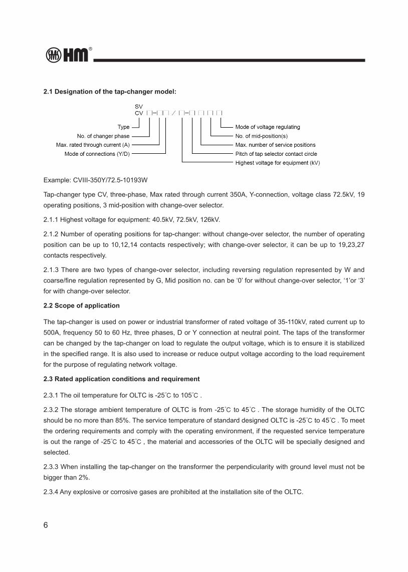
2.1 Designation of the tap-changer model:
Example: CVIII-350Y/72.5-10193W
Tap-changer type CV, three-phase, Max rated through current 350A, Y-connection, voltage class 72.5kV, 19 operating positions, 3 mid-position with change-over selector.
2.1.1 Highest voltage for equipment: 40.5kV, 72.5kV, 126kV.
2.1.2 Number of operating positions for tap-changer: without change-over selector, the number of operating position can be up to 10,12,14 contacts respectively; with change-over selector, it can be up to 19,23,27 contacts respectively.
2.1.3 There are two types of change-over selector, including reversing regulation represented by W and coarse/fine regulation represented by G, Mid position no. can be ‘0’ for without change-over selector, ‘1’or ‘3’ for with change-over selector.
2.2 Scope of application
The tap-changer is used on power or industrial transformer of rated voltage of 35-110kV, rated current up to 500A, frequency 50 to 60 Hz, three phases, D or Y connection at neutral point. The taps of the transformer can be changed by the tap-changer on load to regulate the output voltage, which is to ensure it is stabilized in the specified range. It is also used to increase or reduce output voltage according to the load requirement for the purpose of regulating network voltage.
2.3 Rated application conditions and requirement
2.3.1 The oil temperature for OLTC is -25℃ to 105℃ .
2.3.2 The storage ambient temperature of OLTC is from -25℃ to 45℃ . The storage humidity of the OLTC should be no more than 85%. The service temperature of standard designed OLTC is -25℃ to 45℃ . To meet the ordering requirements and comply with the operating environment, if the requested service temperature is out the range of -25℃ to 45℃ , the material and accessories of the OLTC will be specially designed and selected.
2.3.3 When installing the tap-changer on the transformer the perpendicularity with ground level must not be bigger than 2%.
2.3.4 Any explosive or corrosive gases are prohibited at the installation site of the OLTC.
HM0.460.001
7
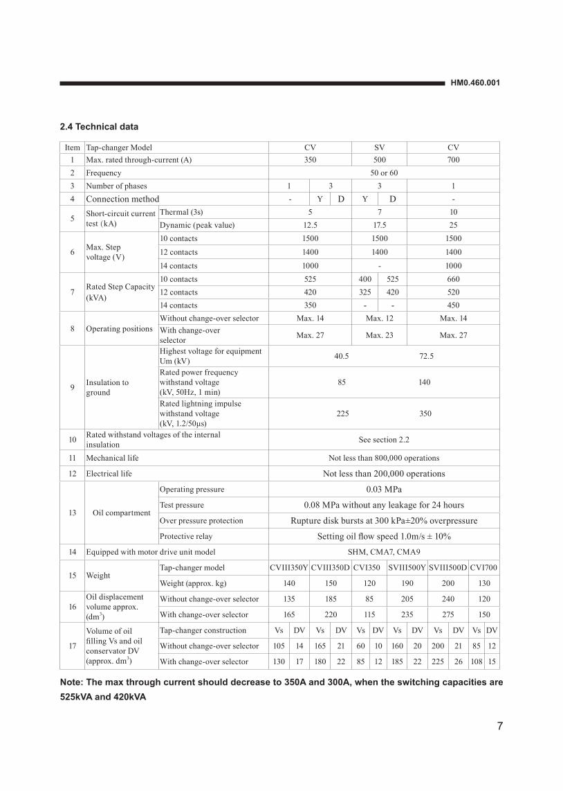
2.4 Technical data
Item Tap-changer Model CV SV CV1 Max. rated through-current (A) 350 500 7002 Frequency 50 or 603 Number of phases 1 3 3 14 Connection method - Y D Y D -
5 Short-circuit current test(kA)
Thermal (3s) 5 7 10Dynamic (peak value) 12.5 17.5 25
6 Max. Step voltage (V)
10 contacts 1500 1500 1500
12 contacts 1400 1400 1400
14 contacts 1000 - 1000
7Rated Step Capacity (kVA)
10 contacts 525 400 525 66012 contacts 420 325 420 52014 contacts 350 - - 450
8 Operating positionsWithout change-over selector Max. 14 Max. 12 Max. 14With change-over selector Max. 27 Max. 23 Max. 27
9 Insulation to ground
Highest voltage for equipment Um (kV) 40.5 72.5
Rated power frequency withstand voltage (kV, 50Hz, 1 min)
85 140
Rated lightning impulse withstand voltage (kV, 1.2/50μs)
225 350
10 Rated withstand voltages of the internal insulation See section 2.2
11 Mechanical life Not less than 800,000 operations
12 Electrical life Not less than 200,000 operations
13 Oil compartment
Operating pressure 0.03 MPa
Test pressure 0.08 MPa without any leakage for 24 hours
Over pressure protection Rupture disk bursts at 300 kPa±20% overpressure
Protective relay Setting oil flow speed 1.0m/s ± 10%
14 Equipped with motor drive unit model SHM, CMA7, CMA9
15 WeightTap-changer model CVIII350Y CVIII350D CVI350 SVIII500Y SVIII500D CVI700
Weight (approx. kg) 140 150 120 190 200 130
16Oil displacement volume approx. (dm3)
Without change-over selector 135 185 85 205 240 120
With change-over selector 165 220 115 235 275 150
17
Volume of oil filling Vs and oil conservator DV (approx. dm3)
Tap-changer construction Vs DV Vs DV Vs DV Vs DV Vs DV Vs DV
Without change-over selector 105 14 165 21 60 10 160 20 200 21 85 12
With change-over selector 130 17 180 22 85 12 185 22 225 26 108 15
Note: The max through current should decrease to 350A and 300A, when the switching capacities are 525kVA and 420kVA
8
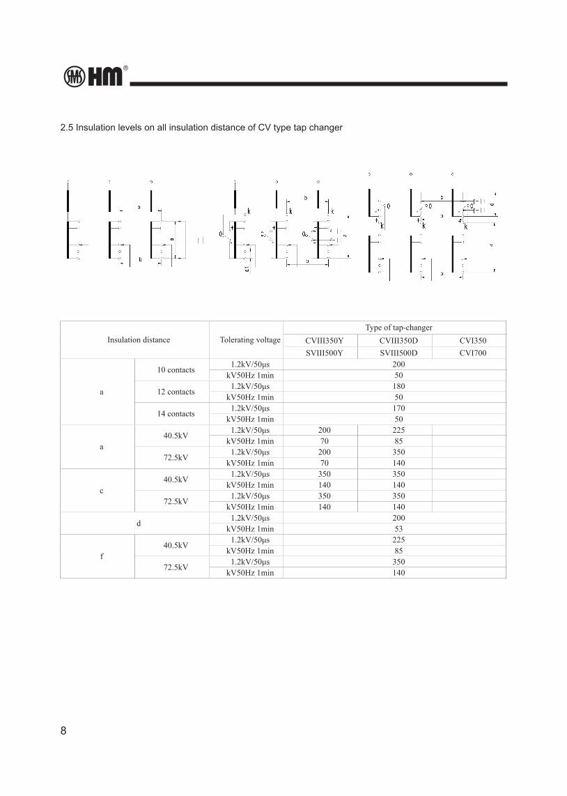
2.5 Insulation levels on all insulation distance of CV type tap changer
Insulation distance Tolerating voltageType of tap-changer
CVIII350Y CVIII350D CVI350SVIII500Y SVIII500D CVI700
a
10 contacts1.2kV/50μs 200
kV50Hz 1min 50
12 contacts1.2kV/50μs 180
kV50Hz 1min 50
14 contacts1.2kV/50μs 170
kV50Hz 1min 50
a40.5kV
1.2kV/50μs 200 225kV50Hz 1min 70 85
72.5kV1.2kV/50μs 200 350
kV50Hz 1min 70 140
c40.5kV
1.2kV/50μs 350 350kV50Hz 1min 140 140
72.5kV1.2kV/50μs 350 350
kV50Hz 1min 140 140
d1.2kV/50μs 200
kV50Hz 1min 53
f40.5kV
1.2kV/50μs 225kV50Hz 1min 85
72.5kV1.2kV/50μs 350
kV50Hz 1min 140
HM0.460.001
9
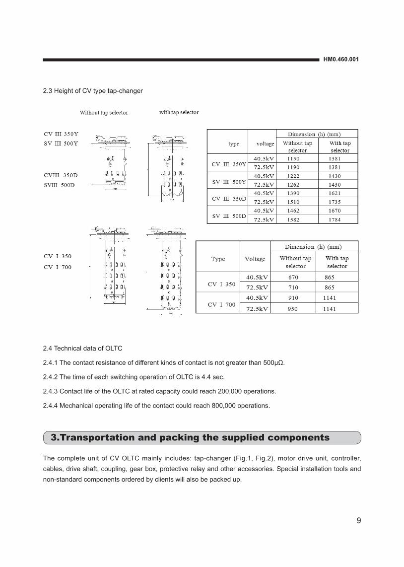
2.3 Height of CV type tap-changer
2.4 Technical data of OLTC
2.4.1 The contact resistance of different kinds of contact is not greater than 500µΩ.
2.4.2 The time of each switching operation of OLTC is 4.4 sec.
2.4.3 Contact life of the OLTC at rated capacity could reach 200,000 operations.
2.4.4 Mechanical operating life of the contact could reach 800,000 operations.
3.Transportation and packing the supplied components
The complete unit of CV OLTC mainly includes: tap-changer (Fig.1, Fig.2), motor drive unit, controller, cables, drive shaft, coupling, gear box, protective relay and other accessories. Special installation tools and non-standard components ordered by clients will also be packed up.
10
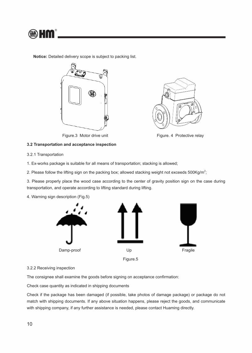
Notice: Detailed delivery scope is subject to packing list.
Figure.3 Motor drive unit Figure. 4 Protective relay
3.2 Transportation and acceptance inspection
3.2.1 Transportation
1. Ex-works package is suitable for all means of transportation; stacking is allowed;
2. Please follow the lifting sign on the packing box; allowed stacking weight not exceeds 500Kg/m2;
3. Please properly place the wood case according to the center of gravity position sign on the case during transportation, and operate according to lifting standard during lifting.
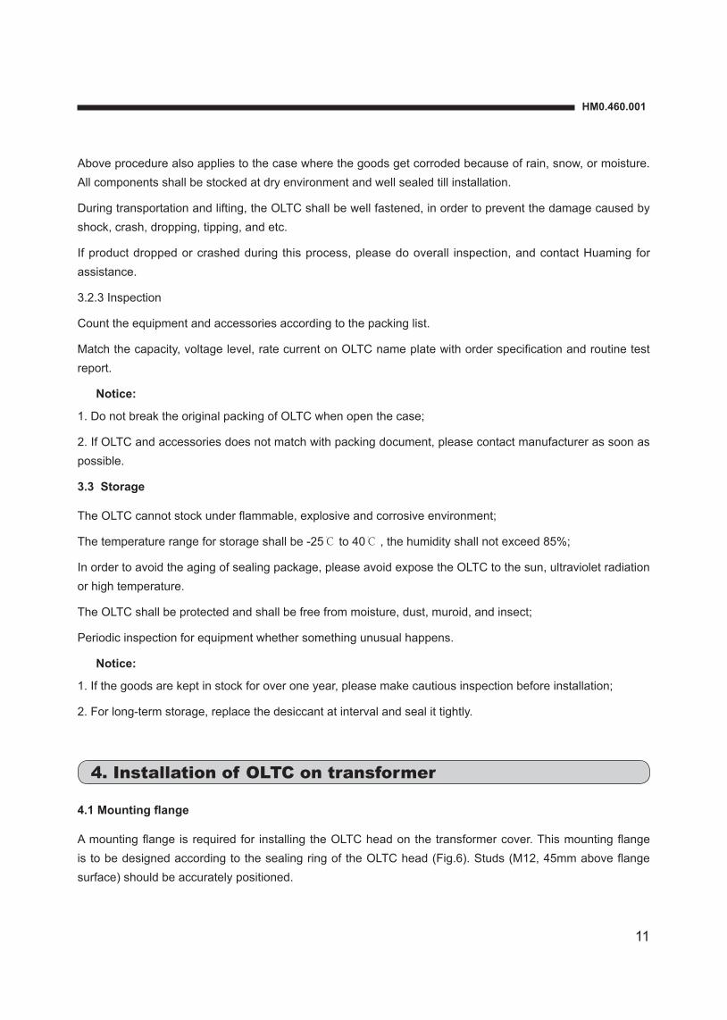
4. Warning sign description (Fig.5)
Damp-proof Up Fragile
Figure.5
3.2.2 Receiving inspection
The consignee shall examine the goods before signing on acceptance confirmation:
Check case quantity as indicated in shipping documents
Check if the package has been damaged (if possible, take photos of damage package) or package do not match with shipping documents. If any above situation happens, please reject the goods, and communicate with shipping company, if any further assistance is needed, please contact Huaming directly.
HM0.460.001
11
Above procedure also applies to the case where the goods get corroded because of rain, snow, or moisture. All components shall be stocked at dry environment and well sealed till installation.
During transportation and lifting, the OLTC shall be well fastened, in order to prevent the damage caused by shock, crash, dropping, tipping, and etc.
If product dropped or crashed during this process, please do overall inspection, and contact Huaming for assistance.
3.2.3 Inspection
Count the equipment and accessories according to the packing list.
Match the capacity, voltage level, rate current on OLTC name plate with order specification and routine test report.
Notice:
1. Do not break the original packing of OLTC when open the case;
2. If OLTC and accessories does not match with packing document, please contact manufacturer as soon as possible.
3.3 Storage
The OLTC cannot stock under flammable, explosive and corrosive environment;
The temperature range for storage shall be -25℃ to 40℃ , the humidity shall not exceed 85%;
In order to avoid the aging of sealing package, please avoid expose the OLTC to the sun, ultraviolet radiation or high temperature.
The OLTC shall be protected and shall be free from moisture, dust, muroid, and insect;
Periodic inspection for equipment whether something unusual happens.
Notice:
1. If the goods are kept in stock for over one year, please make cautious inspection before installation;
2. For long-term storage, replace the desiccant at interval and seal it tightly.
4. Installation of OLTC on transformer
4.1 Mounting flange
A mounting flange is required for installing the OLTC head on the transformer cover. This mounting flange is to be designed according to the sealing ring of the OLTC head (Fig.6). Studs (M12, 45mm above flange surface) should be accurately positioned.

12
Figure.6 head flange Figure.7 sealing gasket
4.2 Installation of the tap-changer head on the transformer cover
Put down the OLTC through transformer head cover mounting flange, and fix OLTC on the mounting flange by using nuts.
Installation procedure as follow:
1. Clean all sealing surfaces (tap-changer head flange, mounting flange and O ring);
2. Put an oil-proof gasket on the mounting flange of the transformer cover;
3. Lift the tap-changer over the transformer cover and lower it carefully into the transformer;
Notice:
Be careful not to damage the tap-changer terminals and tie-in resistor (if the voltage level is higher than 72.5kV, the OLTC might install tie-in resistor).
4. Check whether the position location which is installed on the OLTC head match the design requirement;
5. Fasten the tap-changer head to the mounting flange (24 nuts, with spring gasket; Torque 34 N•m).
Figure.8 standard type OLTC installation diagram
4.3 Tap changer installation on bell type transformer
24XM12
25
45
15
Ø630
Ø 570
7.5°
7.5°
Ø684
EQSTransformer head cover flange
Transformer head cover
Transformer connection flange
Transformer tank cover
Seal gasket
OLTC head flange
11917
6.5
97
Ø570
141
22
HM0.460.001
13
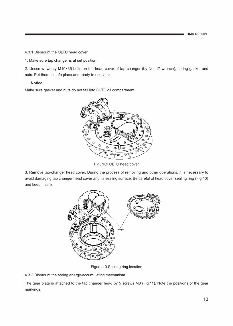
4.3.1 Dismount the OLTC head cover
1. Make sure tap changer is at set position;
2. Unscrew twenty M10×35 bolts on the head cover of tap changer (by No. 17 wrench), spring gasket and nuts. Put them to safe place and ready to use later.
Notice:
Make sure gasket and nuts do not fall into OLTC oil compartment.
Figure.9 OLTC head cover
3. Remove tap-changer head cover. During the process of removing and other operations, it is necessary to avoid damaging tap changer head cover and its sealing surface. Be careful of head cover sealing ring (Fig.10) and keep it safe;
Figure.10 Sealing ring location
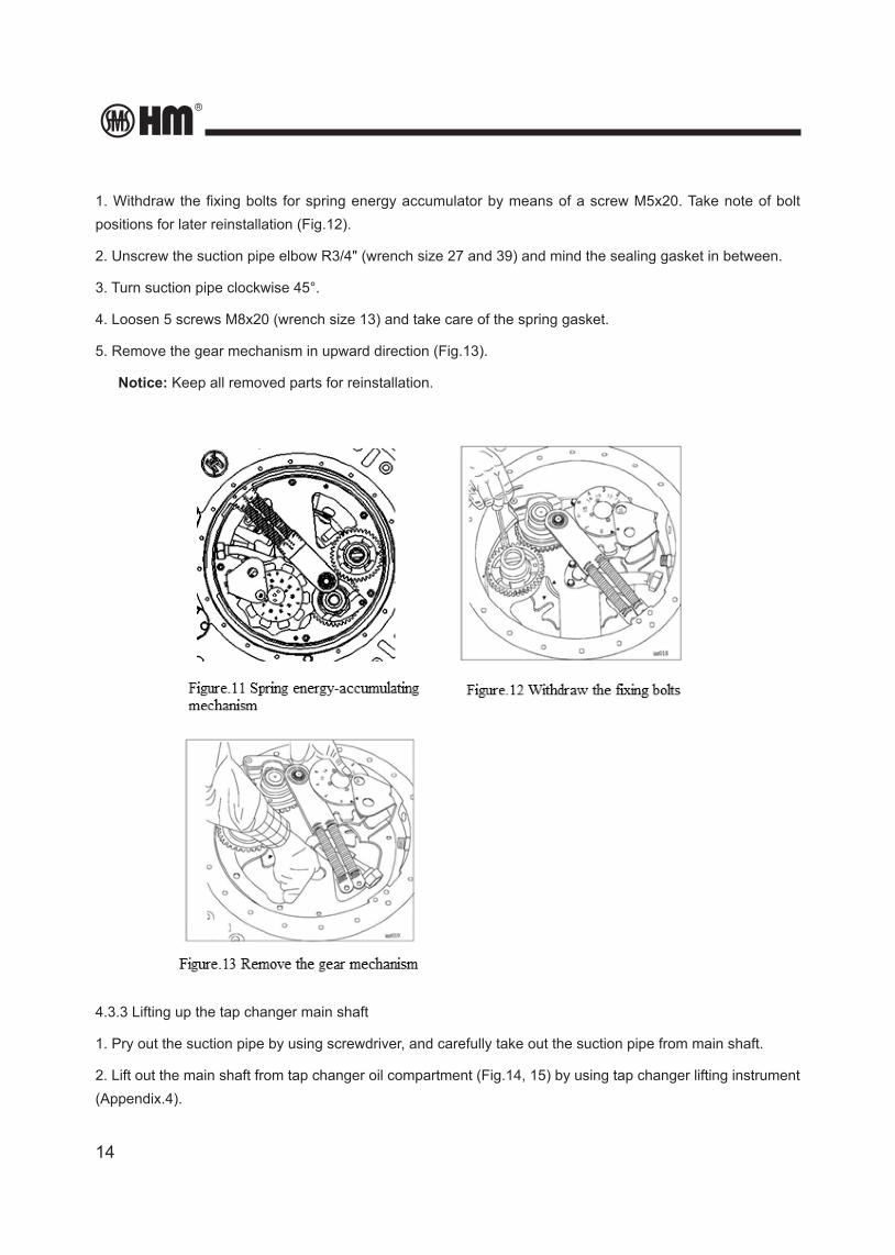
4.3.2 Dismount the spring energy-accumulating mechanism
The gear plate is attached to the tap changer head by 5 screws M8 (Fig.11). Note the positions of the gear markings.
14
1. Withdraw the fixing bolts for spring energy accumulator by means of a screw M5x20. Take note of bolt positions for later reinstallation (Fig.12).
2. Unscrew the suction pipe elbow R3/4" (wrench size 27 and 39) and mind the sealing gasket in between.
3. Turn suction pipe clockwise 45°.
4. Loosen 5 screws M8x20 (wrench size 13) and take care of the spring gasket.
5. Remove the gear mechanism in upward direction (Fig.13).
Notice: Keep all removed parts for reinstallation.
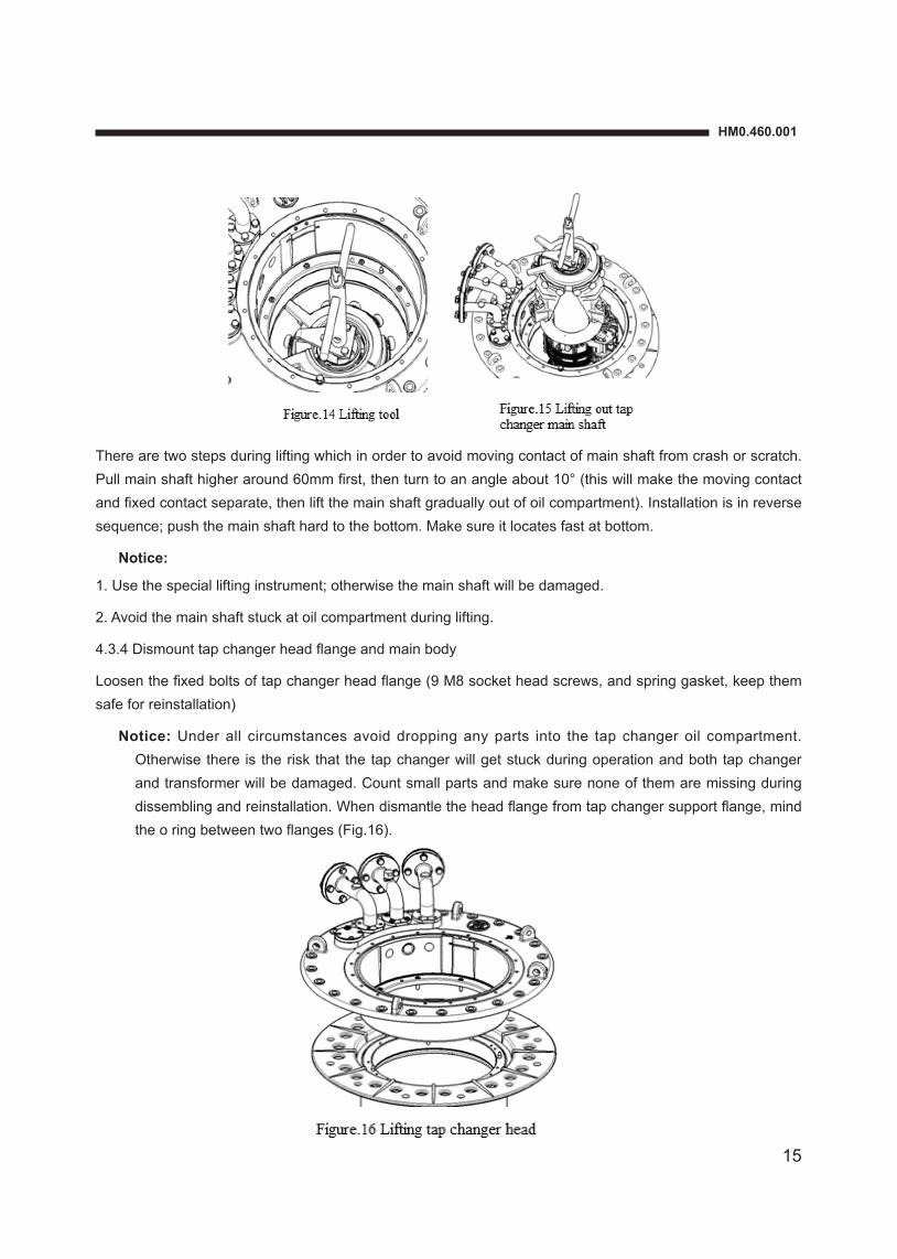
4.3.3 Lifting up the tap changer main shaft
1. Pry out the suction pipe by using screwdriver, and carefully take out the suction pipe from main shaft.
2. Lift out the main shaft from tap changer oil compartment (Fig.14, 15) by using tap changer lifting instrument (Appendix.4).
HM0.460.001
15
There are two steps during lifting which in order to avoid moving contact of main shaft from crash or scratch. Pull main shaft higher around 60mm first, then turn to an angle about 10° (this will make the moving contact and fixed contact separate, then lift the main shaft gradually out of oil compartment). Installation is in reverse sequence; push the main shaft hard to the bottom. Make sure it locates fast at bottom.
Notice:
1. Use the special lifting instrument; otherwise the main shaft will be damaged.
2. Avoid the main shaft stuck at oil compartment during lifting.
4.3.4 Dismount tap changer head flange and main body
Loosen the fixed bolts of tap changer head flange (9 M8 socket head screws, and spring gasket, keep them safe for reinstallation)
Notice: Under all circumstances avoid dropping any parts into the tap changer oil compartment. Otherwise there is the risk that the tap changer will get stuck during operation and both tap changer and transformer will be damaged. Count small parts and make sure none of them are missing during dissembling and reinstallation. When dismantle the head flange from tap changer support flange, mind the o ring between two flanges (Fig.16).
16
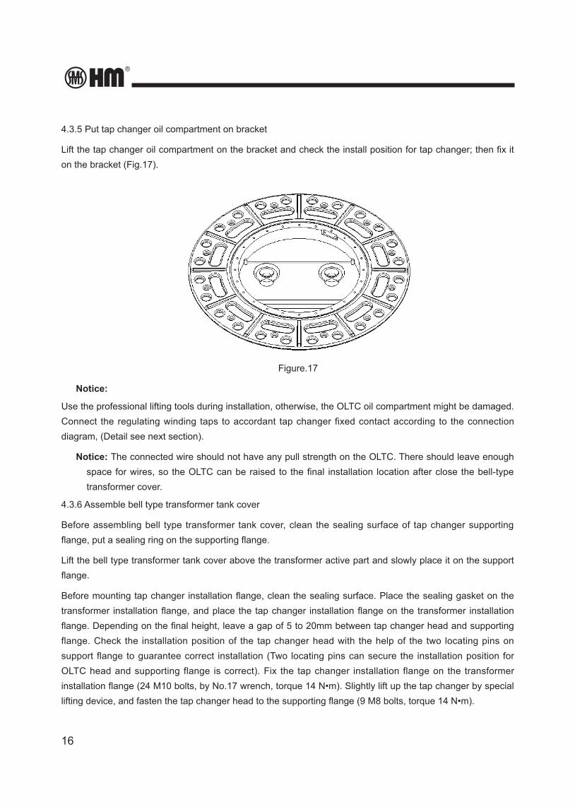
4.3.5 Put tap changer oil compartment on bracket
Lift the tap changer oil compartment on the bracket and check the install position for tap changer; then fix it on the bracket (Fig.17).
Figure.17
Notice:
Use the professional lifting tools during installation, otherwise, the OLTC oil compartment might be damaged. Connect the regulating winding taps to accordant tap changer fixed contact according to the connection diagram, (Detail see next section).
Notice: The connected wire should not have any pull strength on the OLTC. There should leave enough space for wires, so the OLTC can be raised to the final installation location after close the bell-type transformer cover.
4.3.6 Assemble bell type transformer tank cover
Before assembling bell type transformer tank cover, clean the sealing surface of tap changer supporting flange, put a sealing ring on the supporting flange.
Lift the bell type transformer tank cover above the transformer active part and slowly place it on the support flange.
Before mounting tap changer installation flange, clean the sealing surface. Place the sealing gasket on the transformer installation flange, and place the tap changer installation flange on the transformer installation flange. Depending on the final height, leave a gap of 5 to 20mm between tap changer head and supporting flange. Check the installation position of the tap changer head with the help of the two locating pins on support flange to guarantee correct installation (Two locating pins can secure the installation position for OLTC head and supporting flange is correct). Fix the tap changer installation flange on the transformer installation flange (24 M10 bolts, by No.17 wrench, torque 14 N•m). Slightly lift up the tap changer by special lifting device, and fasten the tap changer head to the supporting flange (9 M8 bolts, torque 14 N•m).
HM0.460.001
17
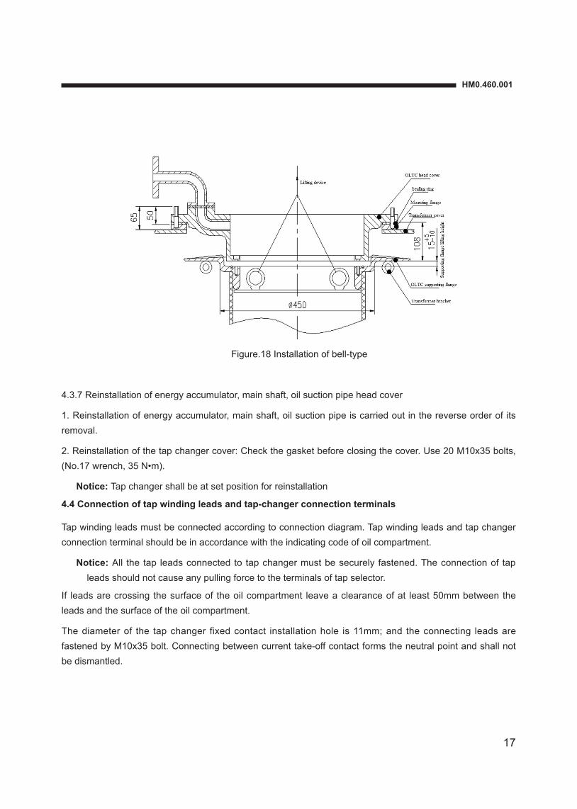
Figure.18 Installation of bell-type
4.3.7 Reinstallation of energy accumulator, main shaft, oil suction pipe head cover
1. Reinstallation of energy accumulator, main shaft, oil suction pipe is carried out in the reverse order of its removal.
2. Reinstallation of the tap changer cover: Check the gasket before closing the cover. Use 20 M10x35 bolts, (No.17 wrench, 35 N•m).
Notice: Tap changer shall be at set position for reinstallation
4.4 Connection of tap winding leads and tap-changer connection terminals
Tap winding leads must be connected according to connection diagram. Tap winding leads and tap changer connection terminal should be in accordance with the indicating code of oil compartment.
Notice: All the tap leads connected to tap changer must be securely fastened. The connection of tap leads should not cause any pulling force to the terminals of tap selector.
If leads are crossing the surface of the oil compartment leave a clearance of at least 50mm between the leads and the surface of the oil compartment.
The diameter of the tap changer fixed contact installation hole is 11mm; and the connecting leads are fastened by M10x35 bolt. Connecting between current take-off contact forms the neutral point and shall not be dismantled.
18
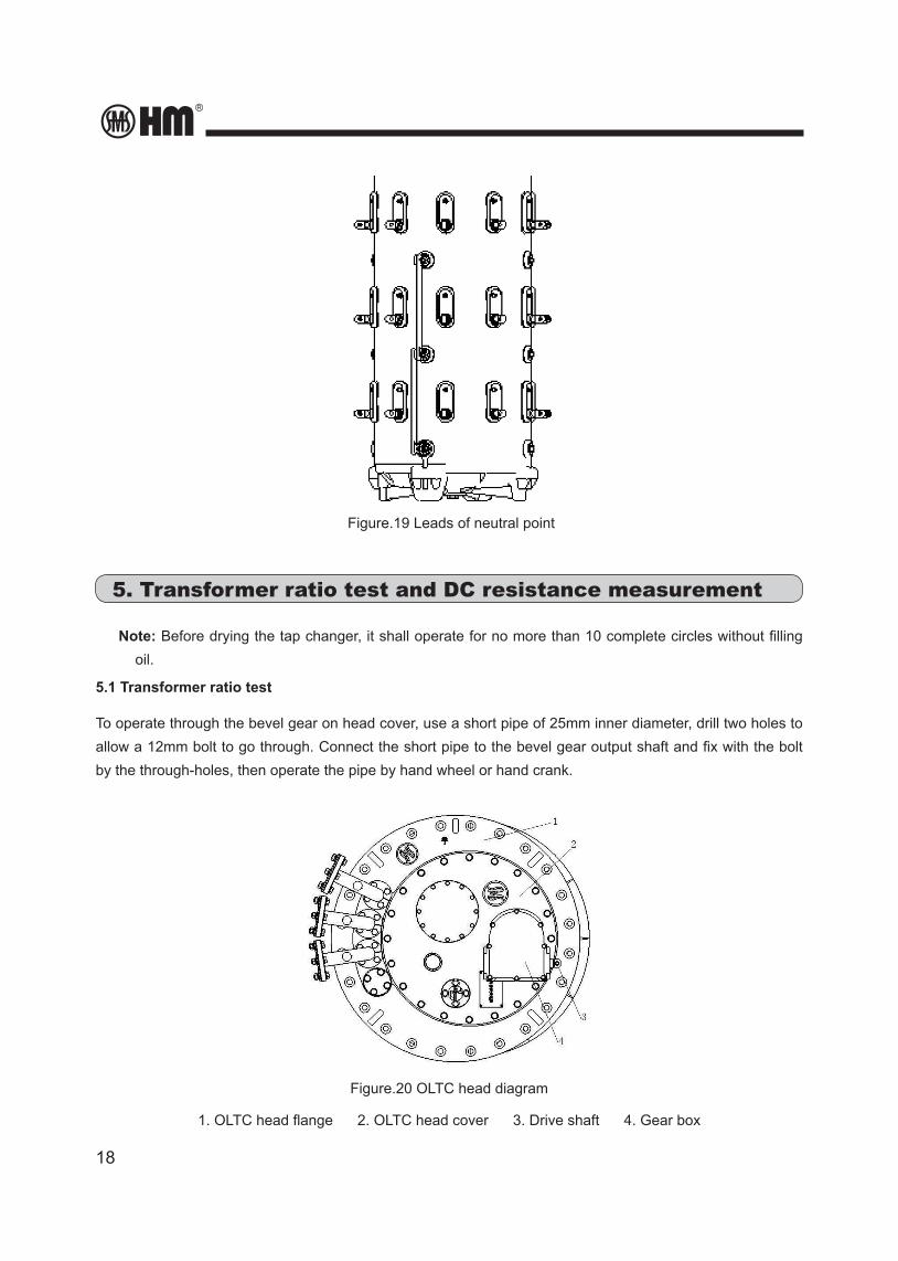
Figure.19 Leads of neutral point
5. Transformer ratio test and DC resistance measurement
Note: Before drying the tap changer, it shall operate for no more than 10 complete circles without filling oil.
5.1 Transformer ratio test
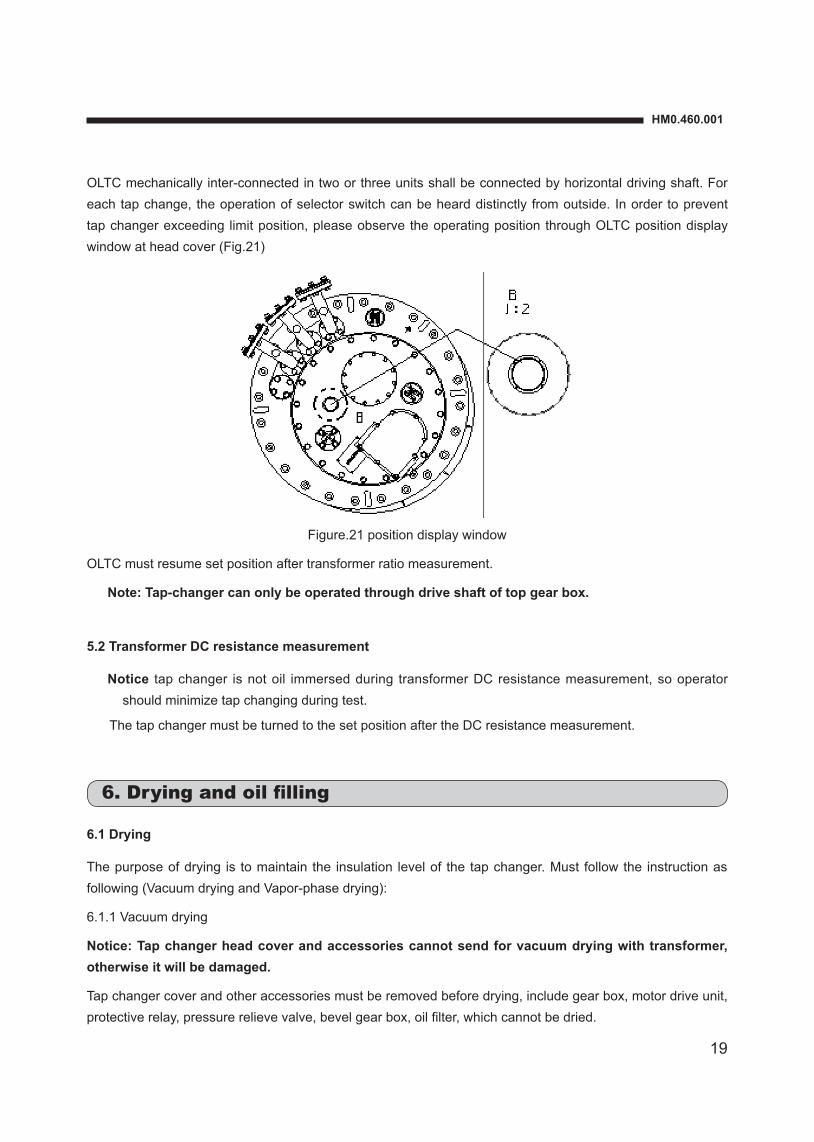
To operate through the bevel gear on head cover, use a short pipe of 25mm inner diameter, drill two holes to allow a 12mm bolt to go through. Connect the short pipe to the bevel gear output shaft and fix with the bolt by the through-holes, then operate the pipe by hand wheel or hand crank.
Figure.20 OLTC head diagram
1. OLTC head flange 2. OLTC head cover 3. Drive shaft 4. Gear box
HM0.460.001
19
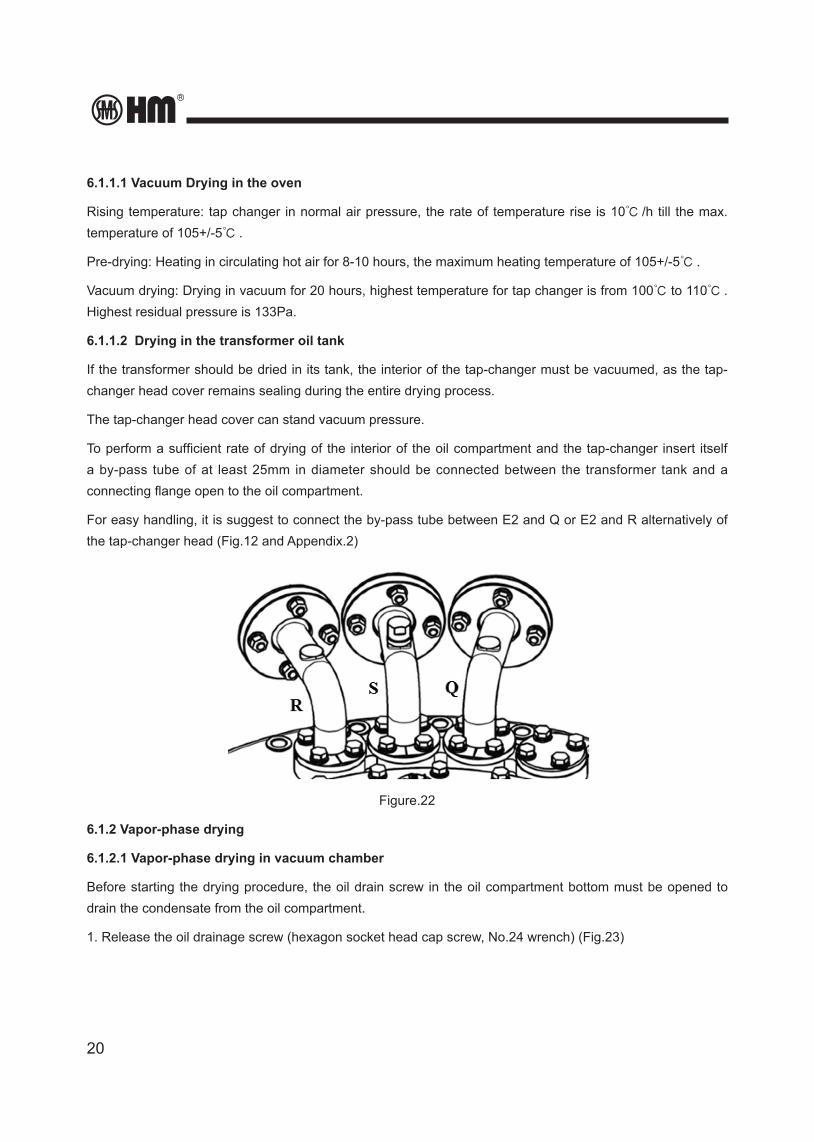
OLTC mechanically inter-connected in two or three units shall be connected by horizontal driving shaft. For each tap change, the operation of selector switch can be heard distinctly from outside. In order to prevent tap changer exceeding limit position, please observe the operating position through OLTC position display window at head cover (Fig.21)
Figure.21 position display window
OLTC must resume set position after transformer ratio measurement.
Note: Tap-changer can only be operated through drive shaft of top gear box.
5.2 Transformer DC resistance measurement
Notice tap changer is not oil immersed during transformer DC resistance measurement, so operator should minimize tap changing during test.
The tap changer must be turned to the set position after the DC resistance measurement.
6. Drying and oil filling
6.1 Drying
The purpose of drying is to maintain the insulation level of the tap changer. Must follow the instruction as following (Vacuum drying and Vapor-phase drying):
6.1.1 Vacuum drying
Notice: Tap changer head cover and accessories cannot send for vacuum drying with transformer, otherwise it will be damaged.
Tap changer cover and other accessories must be removed before drying, include gear box, motor drive unit, protective relay, pressure relieve valve, bevel gear box, oil filter, which cannot be dried.
20
6.1.1.1 Vacuum Drying in the oven
Rising temperature: tap changer in normal air pressure, the rate of temperature rise is 10℃ /h till the max. temperature of 105+/-5℃ .
Pre-drying: Heating in circulating hot air for 8-10 hours, the maximum heating temperature of 105+/-5℃ .
Vacuum drying: Drying in vacuum for 20 hours, highest temperature for tap changer is from 100℃ to 110℃ . Highest residual pressure is 133Pa.
6.1.1.2 Drying in the transformer oil tank
If the transformer should be dried in its tank, the interior of the tap-changer must be vacuumed, as the tap-changer head cover remains sealing during the entire drying process.
The tap-changer head cover can stand vacuum pressure.
To perform a sufficient rate of drying of the interior of the oil compartment and the tap-changer insert itself a by-pass tube of at least 25mm in diameter should be connected between the transformer tank and a connecting flange open to the oil compartment.
For easy handling, it is suggest to connect the by-pass tube between E2 and Q or E2 and R alternatively of the tap-changer head (Fig.12 and Appendix.2)
Figure.22
6.1.2 Vapor-phase drying
6.1.2.1 Vapor-phase drying in vacuum chamber
Before starting the drying procedure, the oil drain screw in the oil compartment bottom must be opened to drain the condensate from the oil compartment.
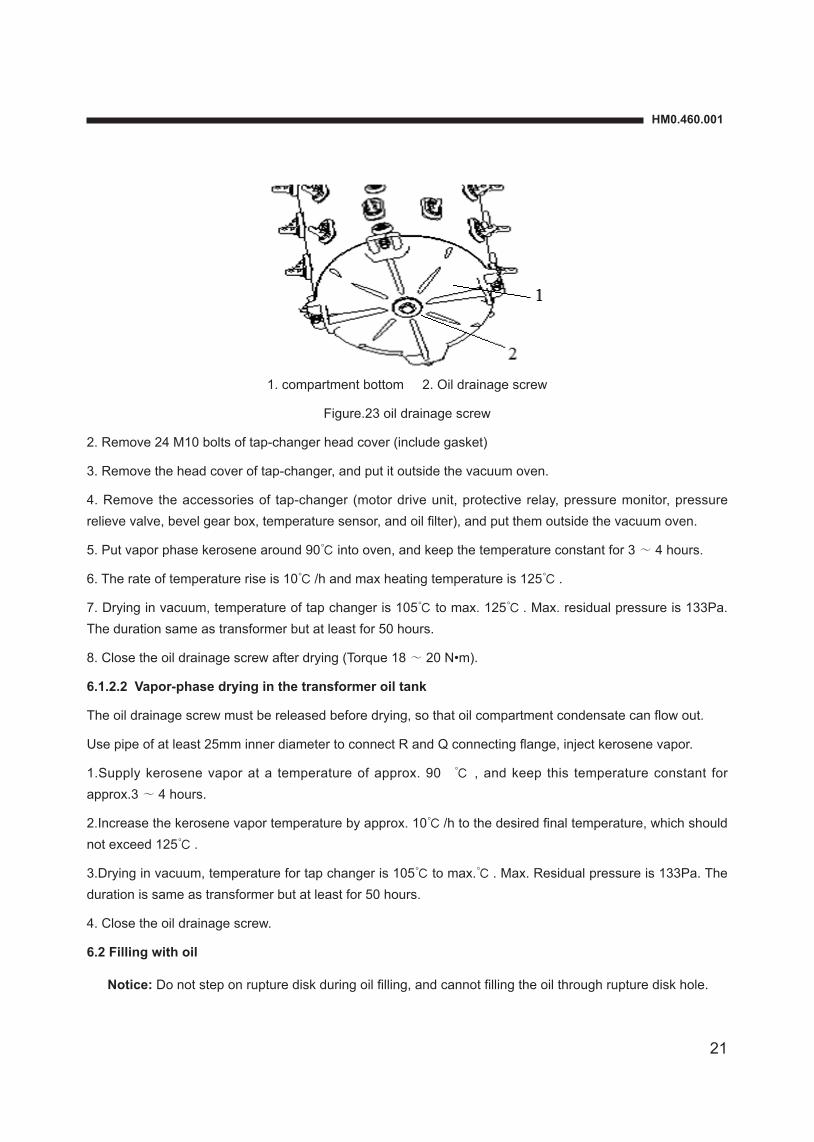
1. Release the oil drainage screw (hexagon socket head cap screw, No.24 wrench) (Fig.23)
HM0.460.001
21
1. compartment bottom 2. Oil drainage screw
Figure.23 oil drainage screw
2. Remove 24 M10 bolts of tap-changer head cover (include gasket)
3. Remove the head cover of tap-changer, and put it outside the vacuum oven.
4. Remove the accessories of tap-changer (motor drive unit, protective relay, pressure monitor, pressure relieve valve, bevel gear box, temperature sensor, and oil filter), and put them outside the vacuum oven.
5. Put vapor phase kerosene around 90℃ into oven, and keep the temperature constant for 3~ 4 hours.
6. The rate of temperature rise is 10℃ /h and max heating temperature is 125℃ .
7. Drying in vacuum, temperature of tap changer is 105℃ to max. 125℃ . Max. residual pressure is 133Pa. The duration same as transformer but at least for 50 hours.
8. Close the oil drainage screw after drying (Torque 18~ 20 N•m).
6.1.2.2 Vapor-phase drying in the transformer oil tank
The oil drainage screw must be released before drying, so that oil compartment condensate can flow out.
Use pipe of at least 25mm inner diameter to connect R and Q connecting flange, inject kerosene vapor.
1.Supply kerosene vapor at a temperature of approx. 90 ℃ , and keep this temperature constant for approx.3~ 4 hours.
2.Increase the kerosene vapor temperature by approx. 10℃ /h to the desired final temperature, which should not exceed 125℃ .
3.Drying in vacuum, temperature for tap changer is 105℃ to max.℃ . Max. Residual pressure is 133Pa. The duration is same as transformer but at least for 50 hours.
4. Close the oil drainage screw.
6.2 Filling with oil
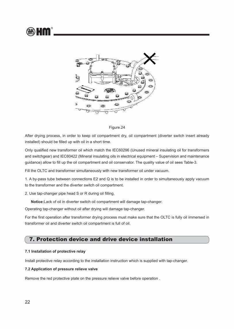
Notice: Do not step on rupture disk during oil filling, and cannot filling the oil through rupture disk hole.
22
Figure.24
After drying process, in order to keep oil compartment dry, oil compartment (diverter switch insert already installed) should be filled up with oil in a short time.
Only qualified new transformer oil which match the IEC60296 (Unused mineral insulating oil for transformers and switchgear) and IEC60422 (Mineral insulating oils in electrical equipment – Supervision and maintenance guidance) allow to fill up the oil compartment and oil conservator. The quality value of oil sees Table-3.
Fill the OLTC and transformer simultaneously with new transformer oil under vacuum.
1. A by-pass tube between connections E2 and Q is to be installed in order to simultaneously apply vacuum to the transformer and the diverter switch oil compartment.
2. Use tap-changer pipe head S or R during oil filling.
Notice:Lack of oil in diverter switch oil compartment will damage tap-changer.
Operating tap-changer without oil after drying will damage tap-changer.
For the first operation after transformer drying process must make sure that the OLTC is fully oil immersed in transformer oil and diverter switch oil compartment is full of oil.
7. Protection device and drive device installation
7.1 Installation of protective relay
Install protective relay according to the installation instruction which is supplied with tap-changer.
7.2 Application of pressure relieve valve
Remove the red protective plate on the pressure relieve valve before operation .
HM0.460.001
23
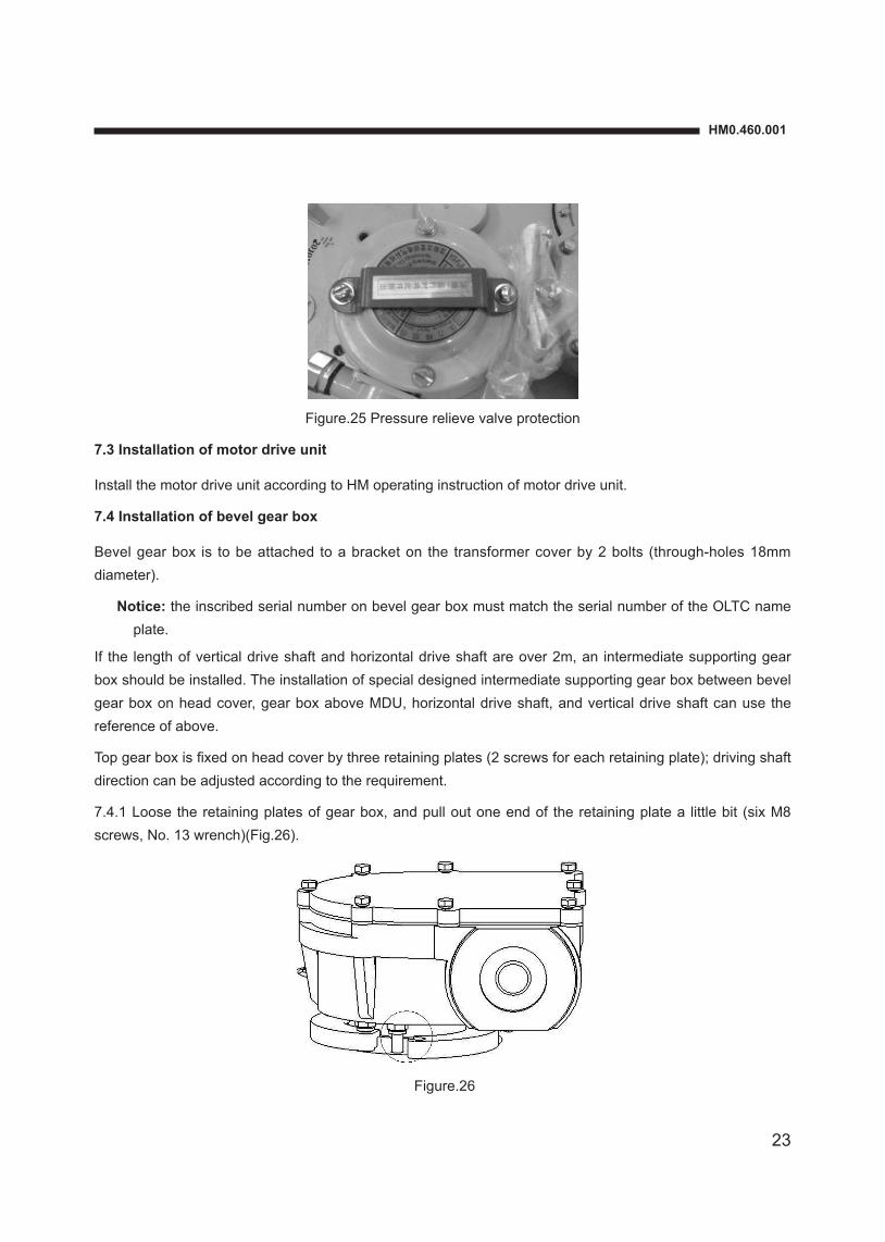
Figure.25 Pressure relieve valve protection
7.3 Installation of motor drive unit
Install the motor drive unit according to HM operating instruction of motor drive unit.
7.4 Installation of bevel gear box
Bevel gear box is to be attached to a bracket on the transformer cover by 2 bolts (through-holes 18mm diameter).
Notice: the inscribed serial number on bevel gear box must match the serial number of the OLTC name plate.
If the length of vertical drive shaft and horizontal drive shaft are over 2m, an intermediate supporting gear box should be installed. The installation of special designed intermediate supporting gear box between bevel gear box on head cover, gear box above MDU, horizontal drive shaft, and vertical drive shaft can use the reference of above.
Top gear box is fixed on head cover by three retaining plates (2 screws for each retaining plate); driving shaft direction can be adjusted according to the requirement.
7.4.1 Loose the retaining plates of gear box, and pull out one end of the retaining plate a little bit (six M8 screws, No. 13 wrench)(Fig.26).
Figure.26
24
7.4.2 Turn top gear box driving shaft to change the direction to meet installation requirement.
Notice: Gear box must not be turned by itself.
7.4.3 Fasten all screws of the retaining plates and fix the gear box tightly (Torque 15 N•m) (Fig.27).
Figure.27
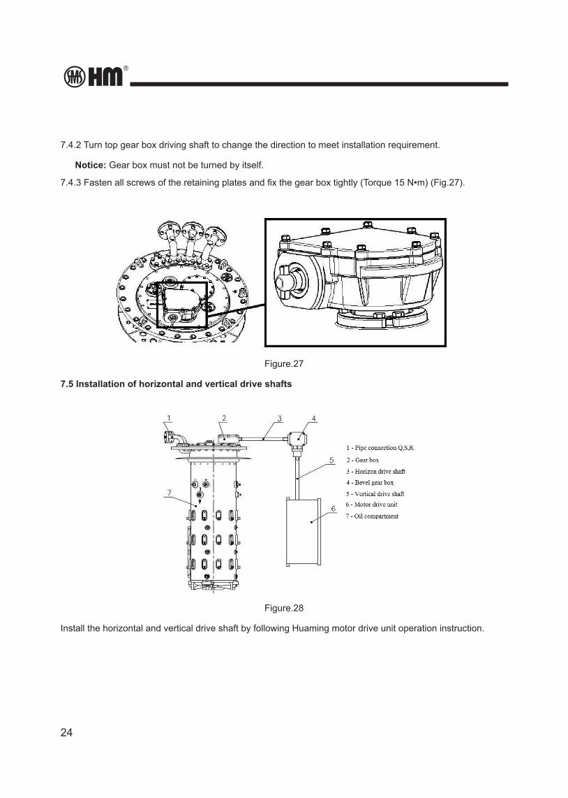
7.5 Installation of horizontal and vertical drive shafts
Figure.28
Install the horizontal and vertical drive shaft by following Huaming motor drive unit operation instruction.
HM0.460.001
25
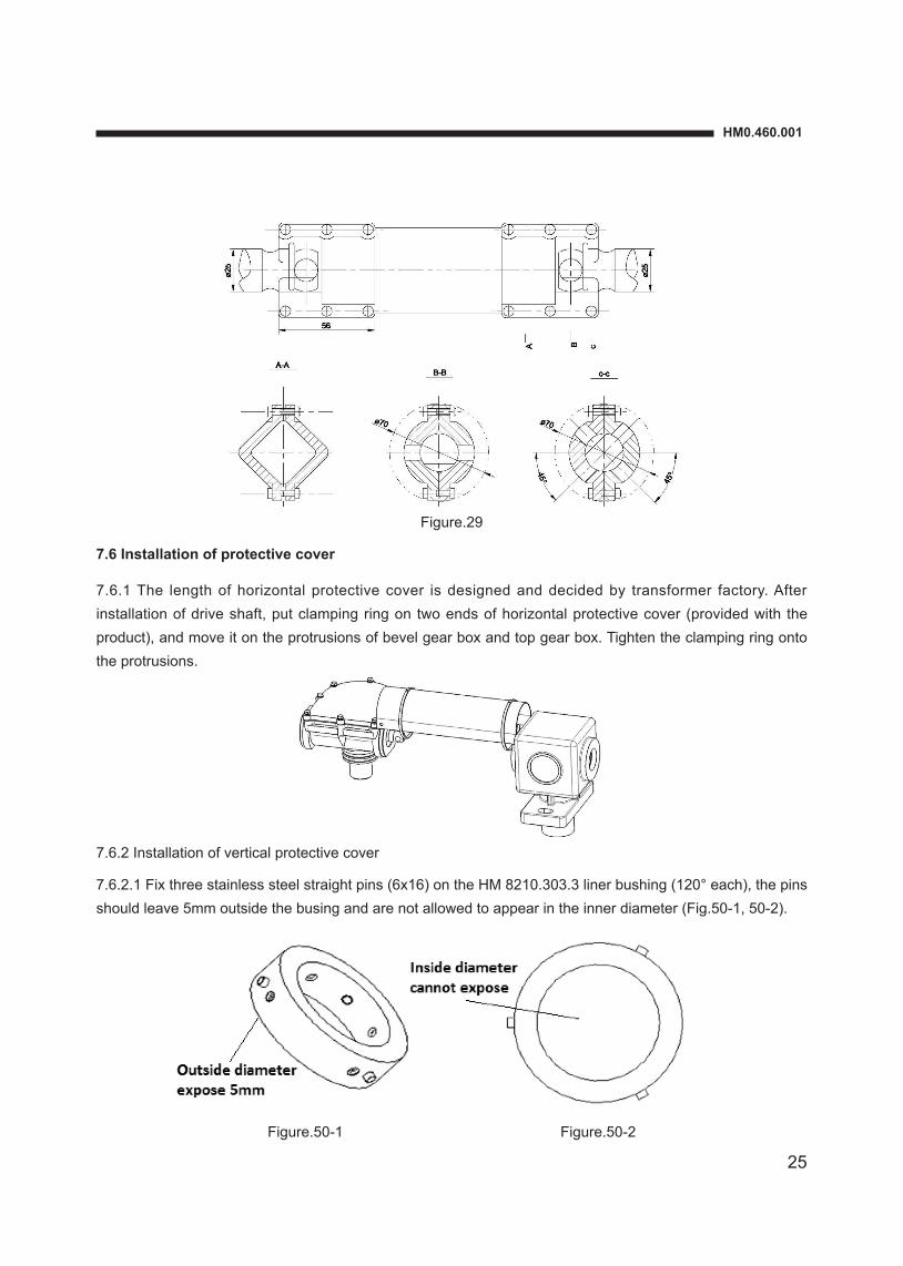
Figure.29
7.6 Installation of protective cover
7.6.1 The length of horizontal protective cover is designed and decided by transformer factory. After installation of drive shaft, put clamping ring on two ends of horizontal protective cover (provided with the product), and move it on the protrusions of bevel gear box and top gear box. Tighten the clamping ring onto the protrusions.
7.6.2 Installation of vertical protective cover
7.6.2.1 Fix three stainless steel straight pins (6x16) on the HM 8210.303.3 liner bushing (120° each), the pins should leave 5mm outside the busing and are not allowed to appear in the inner diameter (Fig.50-1, 50-2).
Figure.50-1 Figure.50-2
26
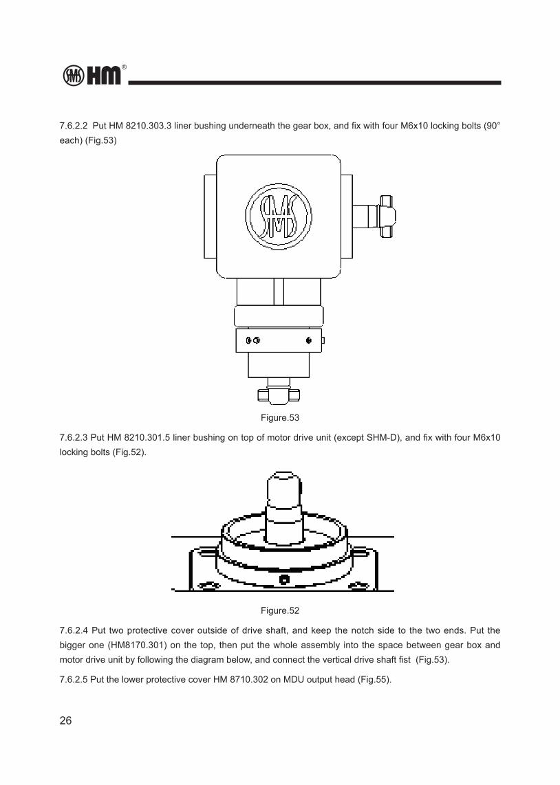
7.6.2.2 Put HM 8210.303.3 liner bushing underneath the gear box, and fix with four M6x10 locking bolts (90° each) (Fig.53)
Figure.53
7.6.2.3 Put HM 8210.301.5 liner bushing on top of motor drive unit (except SHM-D), and fix with four M6x10 locking bolts (Fig.52).
Figure.52
7.6.2.4 Put two protective cover outside of drive shaft, and keep the notch side to the two ends. Put the bigger one (HM8170.301) on the top, then put the whole assembly into the space between gear box and motor drive unit by following the diagram below, and connect the vertical drive shaft fist (Fig.53).
7.6.2.5 Put the lower protective cover HM 8710.302 on MDU output head (Fig.55).
HM0.460.001
27
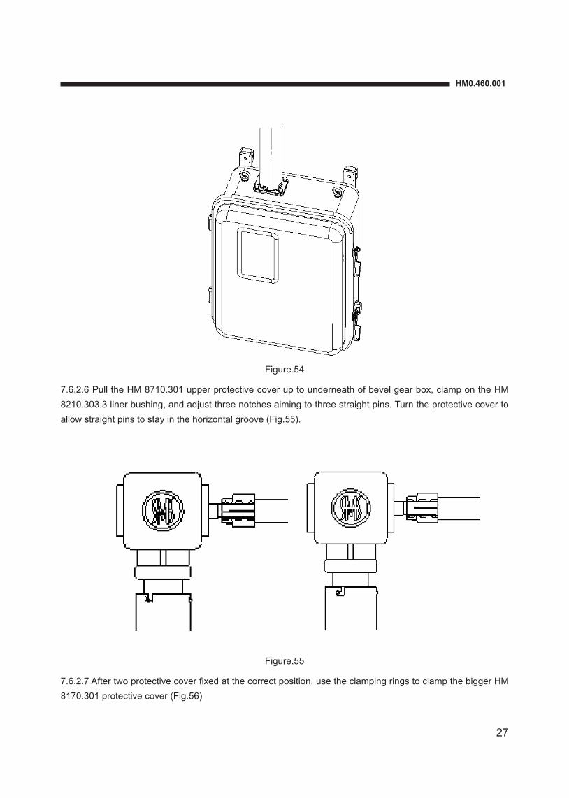
Figure.54
7.6.2.6 Pull the HM 8710.301 upper protective cover up to underneath of bevel gear box, clamp on the HM 8210.303.3 liner bushing, and adjust three notches aiming to three straight pins. Turn the protective cover to allow straight pins to stay in the horizontal groove (Fig.55).
Figure.55
7.6.2.7 After two protective cover fixed at the correct position, use the clamping rings to clamp the bigger HM 8170.301 protective cover (Fig.56)
28
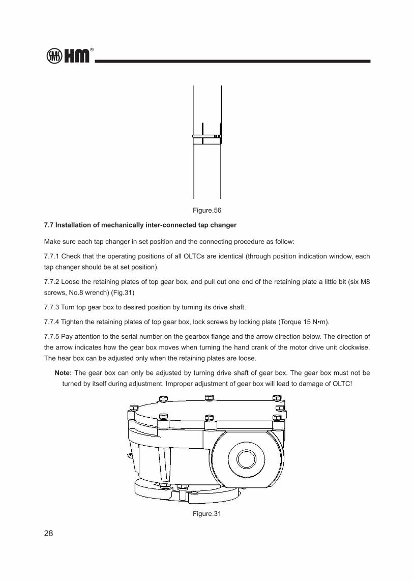
Figure.56
7.7 Installation of mechanically inter-connected tap changer
Make sure each tap changer in set position and the connecting procedure as follow:
7.7.1 Check that the operating positions of all OLTCs are identical (through position indication window, each tap changer should be at set position).
7.7.2 Loose the retaining plates of top gear box, and pull out one end of the retaining plate a little bit (six M8 screws, No.8 wrench) (Fig.31)
7.7.3 Turn top gear box to desired position by turning its drive shaft.
7.7.4 Tighten the retaining plates of top gear box, lock screws by locking plate (Torque 15 N•m).
7.7.5 Pay attention to the serial number on the gearbox flange and the arrow direction below. The direction of the arrow indicates how the gear box moves when turning the hand crank of the motor drive unit clockwise. The hear box can be adjusted only when the retaining plates are loose.
Note: The gear box can only be adjusted by turning drive shaft of gear box. The gear box must not be turned by itself during adjustment. Improper adjustment of gear box will lead to damage of OLTC!
Figure.31
HM0.460.001
29
7.7.6 Turn the output shaft counter-clockwise for one switching of diverter switch for each tap change.
7.7.7 Make sure MDU and tap-changer at the same position.
7.7.8 Install the horizontal drive shaft on each tap changer head. Connect each tap changer by starting from the one closest to motor drive unit.
7.7.9 After installation of all the drive shafts, turn the top gearbox’s drive shaft by 2.5 revolutions more to complete a tap change.
7.7.10 In order to turn OLTC in set position, the drive shaft must operate in clockwise direction. For one complete tap change operation, the bevel gear needs to operate 2.5 circles more after reaching set position and diverter switch acts.
7.7.11 Make sure all tap changers operate at same time (by hearing the diverter switch sound)
7.7.12 Make sure MDU and tap changer at the same tap operation.
7.7.13 Install the vertical drive shaft.
7.8 Position calibration of OLTC drive system
After connecting the tap changer with motor drive unit, manually operate a full cycle of operations before driving by motor. When connecting the tap changer with motor drive unit, the time difference between the completion of diverter switch and the ending of motor drive unit operation should be the same in both direction of rotation. Generally, calibration of tap changer and motor drive connection has been done in the factory. However, for proper operation of the tap changer, the calibration should be performed again by the client before operation. The calibration of connection is carried out according to following procedure:
7.8.1 Turn the crank in the 1→N direction. After the diverter switch has operated (by hearing the switching sound in oil compartment), continue to turn the crank and record the number of turns until a red mark of the green area reaches on the center of the position indication window. Record the number of turns as “m”.
7.8.2 Turn the crank in the reverse direction N→1 to return to its set position. Record the number of turn as “K” in the same ways as mentioned above.
7.8.3 The connection is correct if the m=K. If m≠K and m-K>1, then the difference of turns shall be balanced. Loosen the vertical driving shaft, turn the crank (m-K)/2 turns in the direction of increment of turns, and then connect the vertical driving shaft to the motor drive unit.
7.8.4 Calibrate the difference of turns between the motor drive unit and the tap changer as above, till the same number of turns in both directions, i.e. m=K.
Example:
• Calibration of the connection between CV type tap changer and SHM motor drive unit: Turn from position 10 (setting position) to position 11, m=5 turns, Turn backward from position 11 to position 10 (the original setting position), the K=3 turns. The difference of turns of the handle m-K=5-3=2 turns.
30
• Turns to be adjusted (m-K)/2=(5-3)/2=1 turn.
• Loosen the connection between the vertical driving shaft and the motor drive unit. Turn the crank in the direction 10→11 for one turn.
• Reconnect the driving shaft.
• Check whether the difference of turns in both directions has been balanced.
a. Record number of turns “m” and “K” under connected condition.
b. Turn (m-K)/2 turns in the direction of more recorded turns after loosening of connection.
c. Again make connection and verify until m=K.
8. Tap-changer routine test and pre-test preparation
8.1 Preparation before test
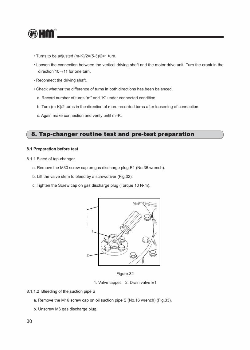
8.1.1 Bleed of tap-changer
a. Remove the M30 screw cap on gas discharge plug E1 (No.36 wrench).
b. Lift the valve stem to bleed by a screwdriver (Fig.32).
c. Tighten the Screw cap on gas discharge plug (Torque 10 N•m).
Figure.32
1. Valve tappet 2. Drain valve E1
8.1.1.2 Bleeding of the suction pipe S
a. Remove the M16 screw cap on oil suction pipe S (No.16 wrench) (Fig.33).
b. Unscrew M6 gas discharge plug.
HM0.460.001
31
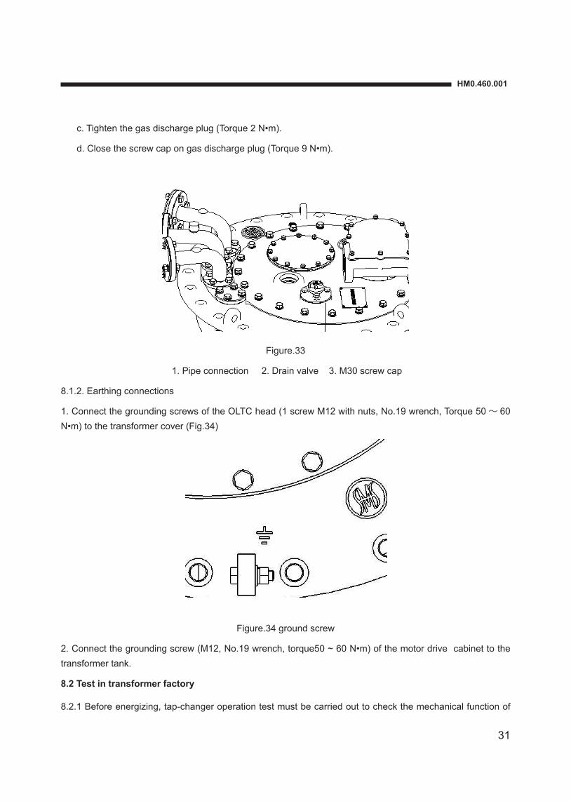
c. Tighten the gas discharge plug (Torque 2 N•m).
d. Close the screw cap on gas discharge plug (Torque 9 N•m).
Figure.33
1. Pipe connection 2. Drain valve 3. M30 screw cap
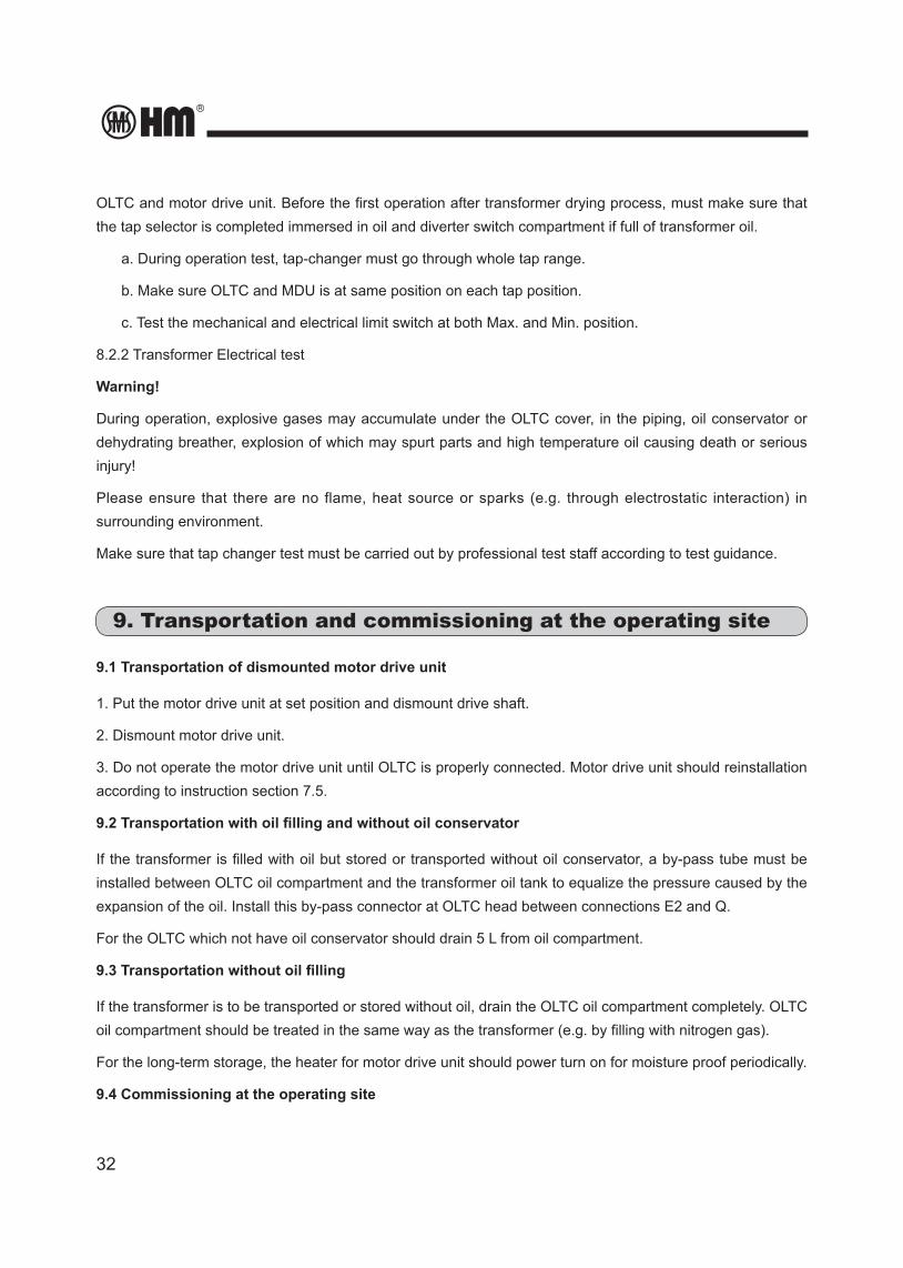
8.1.2. Earthing connections
1. Connect the grounding screws of the OLTC head (1 screw M12 with nuts, No.19 wrench, Torque 50 ~ 60 N•m) to the transformer cover (Fig.34)
Figure.34 ground screw
2. Connect the grounding screw (M12, No.19 wrench, torque50 ~ 60 N•m) of the motor drive cabinet to the transformer tank.
8.2 Test in transformer factory
8.2.1 Before energizing, tap-changer operation test must be carried out to check the mechanical function of
32
OLTC and motor drive unit. Before the first operation after transformer drying process, must make sure that the tap selector is completed immersed in oil and diverter switch compartment if full of transformer oil.
a. During operation test, tap-changer must go through whole tap range.
b. Make sure OLTC and MDU is at same position on each tap position.
c. Test the mechanical and electrical limit switch at both Max. and Min. position.
8.2.2 Transformer Electrical test
Warning!
During operation, explosive gases may accumulate under the OLTC cover, in the piping, oil conservator or dehydrating breather, explosion of which may spurt parts and high temperature oil causing death or serious injury!
Please ensure that there are no flame, heat source or sparks (e.g. through electrostatic interaction) in surrounding environment.
Make sure that tap changer test must be carried out by professional test staff according to test guidance.
9. Transportation and commissioning at the operating site
9.1 Transportation of dismounted motor drive unit
1. Put the motor drive unit at set position and dismount drive shaft.
2. Dismount motor drive unit.
3. Do not operate the motor drive unit until OLTC is properly connected. Motor drive unit should reinstallation according to instruction section 7.5.
9.2 Transportation with oil filling and without oil conservator
If the transformer is filled with oil but stored or transported without oil conservator, a by-pass tube must be installed between OLTC oil compartment and the transformer oil tank to equalize the pressure caused by the expansion of the oil. Install this by-pass connector at OLTC head between connections E2 and Q.
For the OLTC which not have oil conservator should drain 5 L from oil compartment.
9.3 Transportation without oil filling
If the transformer is to be transported or stored without oil, drain the OLTC oil compartment completely. OLTC oil compartment should be treated in the same way as the transformer (e.g. by filling with nitrogen gas).
For the long-term storage, the heater for motor drive unit should power turn on for moisture proof periodically.
9.4 Commissioning at the operating site

HM0.460.001
33
Maker sure that oil compartment is full of oil before commissioning, and the oil should be injected from oil conservator; the oil levels of transformer’s and tap-changer's should more or less the same.
Make sure that tap selector is fully oil immersed in transformer oil and oil compartment is full of oil before commissioning.
1. Bleed of OLTC following the instructions in 8.1.1.
2. Trial operation following the instruction in 8.2.1.
3. Make sure oil conservator Min. oil level signal is connected to circuit breaker’s tripping circuit.
4. Inspect whether the protective relay is functional by following the operation instructions of HM protective relay QJ-25.
5. Remove the red locking plate of pressure relieve valve before operation.
Once the transformer has been switched on, ensure that the inrush current impulse has fully subsided before tap changing. The inrush current impulses are usually several times of the transformer rated current and can overload the OLTC during tap changing. After the transformer has been switched on and the inrush current impulse has subsided, OLTC operations can be performed with or without load.
Before applying voltage to the transformer, trial operations must be carried out to check the mechanical functions of tap changer and motor drive unit. For these test operations the tap changer at least make ten full cycles of operations. Make sure the tap changer and motor drive unit are at same position for each switching.
Check, the electrical and mechanical end position limitation at Max. and Min. positions. According to instruction above, check the function of the protective relay. The protective relay has to be connected into the tripping circuit of the circuit breakers. Make sure that the circuit breakers switch off the transformer when test button “OFF” of the protective relay is pressed. Be sure that they energize the transformer only after test button “IN SERVICE” of the protective relay has been pressed. After energizing transformer, test the tap changer operation on load. The accumulated gas beneath head cover may lead small amount oil leakage.
It is necessary to carried out the periodical inspection for tap changer head cover, protective relay, and motor drive unit.
10. OLTC maintenance
Notice: In order to guarantee the reliability of OLTC, end user should do maintenance at certain interval. The ignorance of maintenance may cause serious accident.
10.1 OLTC maintenance
1. For safety purpose, it is recommended to have first maintenance after two years or 20,000 operations, whichever comes first (For advice only).
2. After that, the tap changer should have routine maintenance for every 7 years or after the number of operations indicated in Table-2, whichever comes first.
34
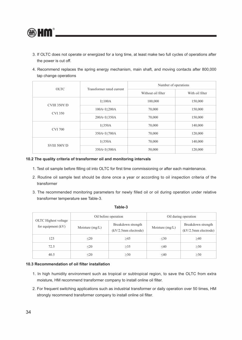
3. If OLTC does not operate or energized for a long time, at least make two full cycles of operations after the power is cut off.
4. Recommend replaces the spring energy mechanism, main shaft, and moving contacts after 800,000 tap change operations
OLTC Transformer rated currentNumber of operations
Without oil filter With oil filter
CVIII 350Y/D
CVI 350
I≤100A 100,000 150,000
100A<I≤200A 70,000 150,000
200A<I≤350A 70,000 150,000
CVI 700I≤350A 70,000 140,000
350A<I≤700A 70,000 120,000
SVIII 500Y/DI≤350A 70,000 140,000
350A<I≤500A 50,000 120,000
10.2 The quality criteria of transformer oil and monitoring intervals
1. Test oil sample before filling oil into OLTC for first time commissioning or after each maintenance.
2. Routine oil sample test should be done once a year or according to oil inspection criteria of the transformer
3. The recommended monitoring parameters for newly filled oil or oil during operation under relative transformer temperature see Table-3.
Table-3
OLTC Highest voltage
for equipment (kV)
Oil before operation Oil during operation
Moisture (mg/L)Breakdown strength
(kV/2.5mm electrode)Moisture (mg/L)
Breakdown strength
(kV/2.5mm electrode)
123 ≤20 ≥45 ≤30 ≥40
72.5 ≤20 ≥35 ≤40 ≥30
40.5 ≤20 ≥30 ≤40 ≥30
10.3 Recommendation of oil filter installation
1. In high humidity environment such as tropical or subtropical region, to save the OLTC from extra moisture, HM recommend transformer company to install online oil filter.
2. For frequent switching applications such as industrial transformer or daily operation over 50 times, HM strongly recommend transformer company to install online oil filter.
HM0.460.001
35
3. For OLTC with highest equipment voltage of 123kV or above, HM strongly recommend transformer company to install online oil filter.
11. Appendix
Appendix 1 Transformer connection flange for CV OLTC, overall dimension .......................................... 36
Appendix 2 CV OLTC head flange for standard tank type, overall dimensions ....................................... 37
Appendix 3 CV OLTC head flange installation for bell-type, overall dimensions ..................................... 38
Appendix 4 OLTC lifting tool diagram ....................................................................................................... 39
Appendix 5 Overall dimension of protective relay .................................................................................... 40
Appendix 6 SHM- III Motor drive unit ....................................................................................................... 41
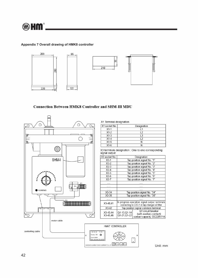
Appendix 7 Overall drawing of HMK8 controller ...................................................................................... 42
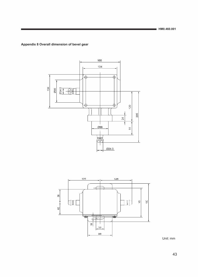
Appendix 8 Overall dimension of bevel gear ........................................................................................... 43
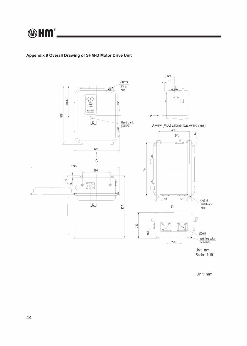
Appendix 9 Overall drawing of SHM-D Motor drive unit .......................................................................... 44
Appendix 10 Overall drawing of SHM-K controller .................................................................................. 45
36
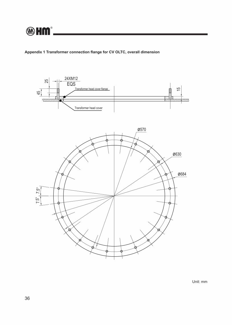
Appendix 1 Transformer connection flange for CV OLTC, overall dimension
Unit: mm
24XM12
25
45
15
ø630
ø570
7.5°
7.5°
ø684
EQSTransformer head cover flange
Transformer head cover
HM0.460.001
37
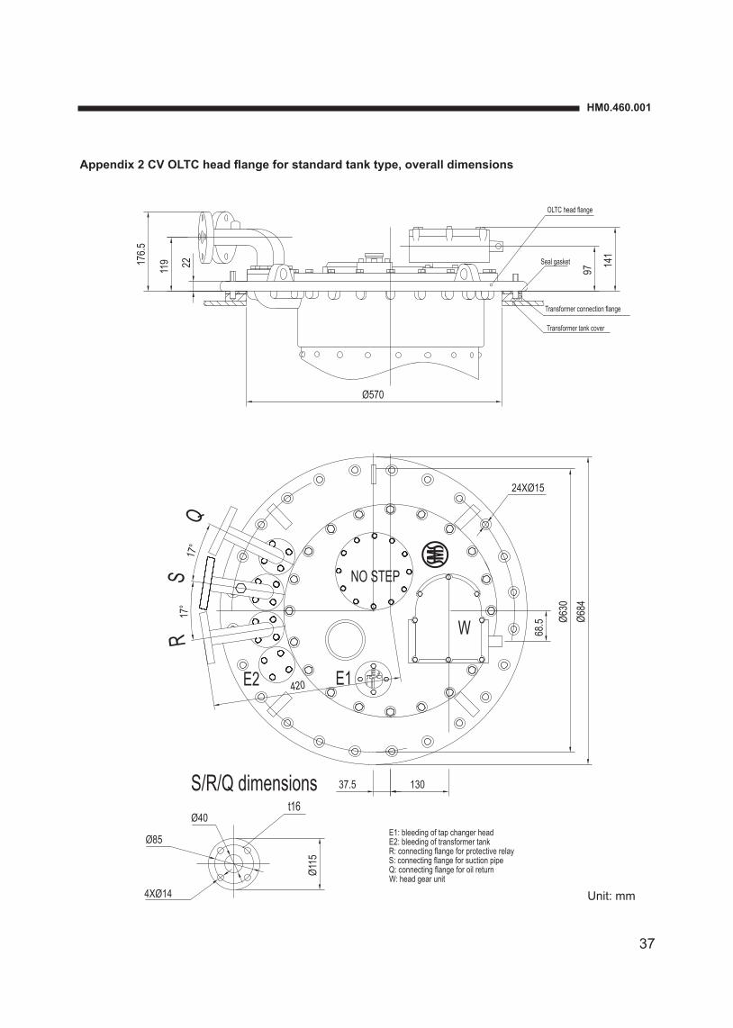
Appendix 2 CV OLTC head flange for standard tank type, overall dimensions
Unit: mm
17°
17°
13037.5
QS
R
NO STEP
E2 E1
68.5
Transformer connection flange
Transformer tank cover
Seal gasket
OLTC head flange
11917
6.5
97
Ø570
420
141
Ø630
24XØ15
W Ø684
22
S/R/Q dimensions
4XØ14
Ø115
Ø40
Ø85
t16
E1: bleeding of tap changer headE2: bleeding of transformer tankR: connecting flange for protective relayS: connecting flange for suction pipeQ: connecting flange for oil returnW: head gear unit
Unit: mm
38
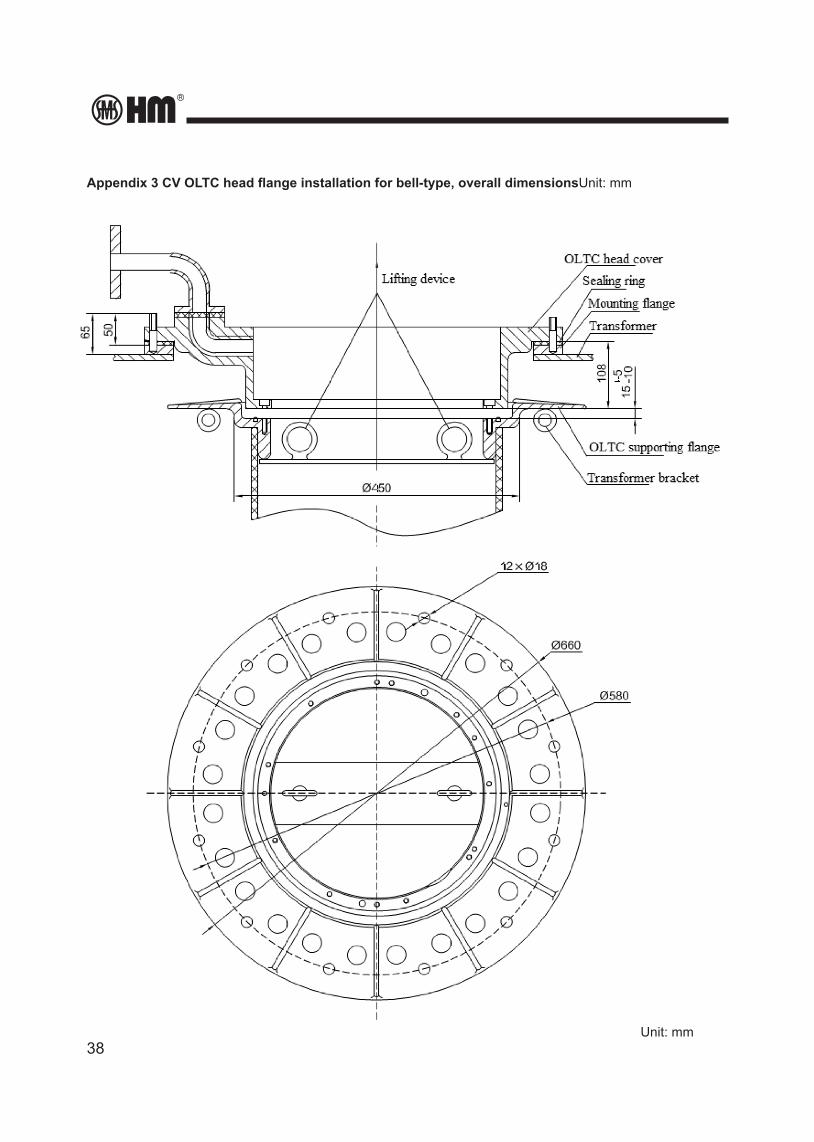
Appendix 3 CV OLTC head flange installation for bell-type, overall dimensionsUnit: mm
Unit: mm
HM0.460.001
39
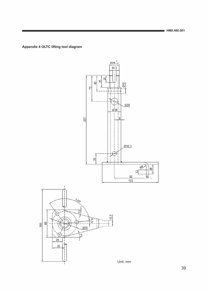
Appendix 4 OLTC lifting tool diagram
Unit: mm
40
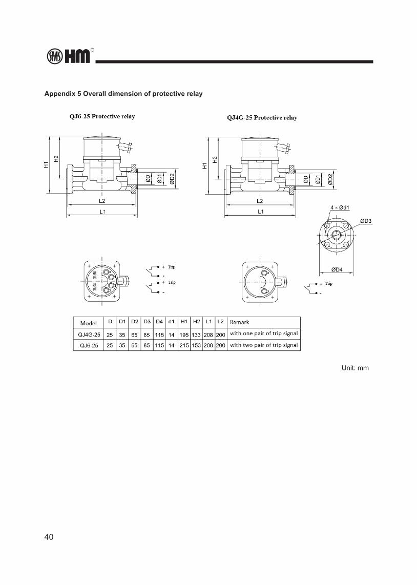
Appendix 5 Overall dimension of protective relay
Unit: mm
HM0.460.001
41
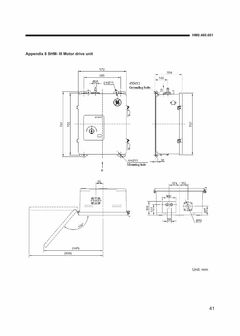
Appendix 6 SHM- III Motor drive unit
Unit: mm
42
Appendix 7 Overall drawing of HMK8 controller
Unit: mm
HM0.460.001
43
Appendix 8 Overall dimension of bevel gear
Unit: mm
44
Appendix 9 Overall Drawing of SHM-D Motor Drive Unit
Unit: mm
43582 44
744
4XØ15
earthling bolts M12X25228
160
816
638
SHM-D
Nameplate
14910
A
C
A view (MDU cabinet backward view)
Ø20.5
A
B
359
390
C Installationhole
Unit: mmScale: 1:10
82
2XØ24
134
lifting hole
82
446.
5
Hand crankposition
877
1245
50 50
36
HM0.460.001
45
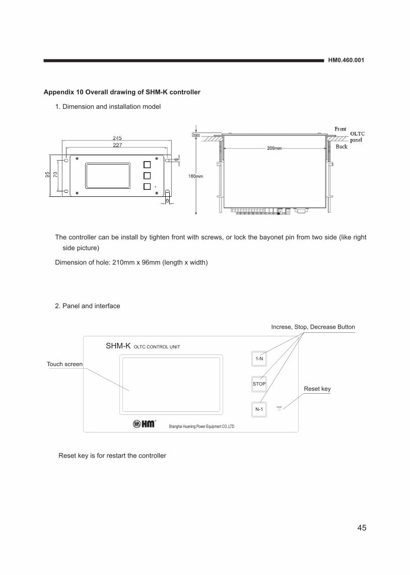
Appendix 10 Overall drawing of SHM-K controller
1. Dimension and installation model
The controller can be install by tighten front with screws, or lock the bayonet pin from two side (like right side picture)
Dimension of hole: 210mm x 96mm (length x width)
2. Panel and interface
Reset key is for restart the controller
Touch screen
Reset key
Increse, Stop, Decrease Button
SHM-K
Reset
N-1
1-N
STOP
OLTC CONTROL UNIT
Shanghai Huaming Power Equipment CO.,LTD
46
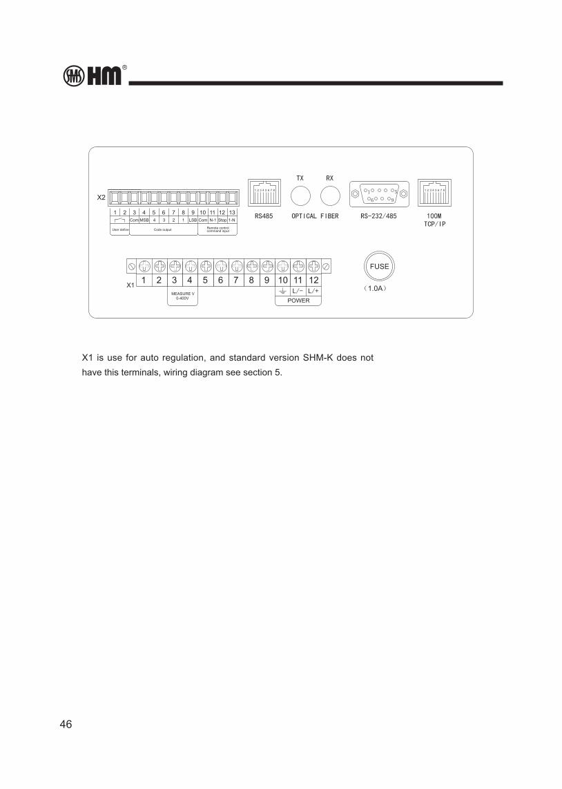
X1 is use for auto regulation, and standard version SHM-K does not have this terminals, wiring diagram see section 5.
X1 9 10 12115 6 873 421
POWERL/+L/-
FUSE
(1.0A)
RXTX
RS485 OPTICAL FIBER RS-232/485TCP/IP100M
1 2 43 7 8651
6
5
9
5 6 873 421
X2
LSB
9 10 1211 135 6 873 4211-NStopN-1ComCom MSB 34 12
User define Code output command inputRemote control
MEASURE V0-400V
SHM-K
Reset
N-1
1-N
STOP
OLTC CONTROL UNIT
Shanghai Huaming Power Equipment CO.,LTD

HM0.460.001
47

Shanghai Huaming Power Equipment Co., Ltd. Address: No 977 Tong Pu Road, Shanghai 200333, P.R.China Tel: +86 21 5270 3965 (direct) +86 21 5270 8966 Ext. 8688 / 8123 / 8698 / 8158 / 8110 / 8658 Fax: +86 21 5270 2715 Web: www.huaming.com E-mail: [email protected]
2012.02