on-orbit temperature field calculation and analysis for
TRANSCRIPT
On-orbit temperature field calculation and analysis for large net-shape deployable antennas
Y. Q. Bi1, J. Wang1,2 & X. Y. Li1 1Beijing Institute of Spacecraft Environment Engineering, China 2Science and Technology on Reliability and Environmental Engineering Laboratory, China
Abstract
Large net-shape deployable antenna reflectors are currently a perfect configuration type for large satellites, and the shape precision affects the performance of antennas greatly. The calculation of the temperature field is fundamental to an analysis of the shape precision. This paper presents a method for calculating the on-orbit temperature field for large net-shape deployable antennas, and gets the temperature by using a numerical calculation. The results support and give a certain reference for an analysis of its shape precision and the antenna thermal testing design. Keywords: large net-shape deployable antenna, on-orbit, temperature field, thermal testing.
1 Introduction
The net-shape deployable antennas reflector has larger applications compared to the configuration of other reflectors, and the antenna reflector’s diameter is arranged from 6 meters to 150 meters. Moreover, the structure of reflector is simple, which can enlarge the diameter in a certain range under the same structure type without proportional increase in mass. So using this type antenna reflector is a good choice for large satellite. The reflector is shown as figure 1. One of the important indicators of antenna is the shape precision. The Ku antenna deployable reflector’s RMS is 0.245 meter, which is used for AstroMesh Corporation’s living broadcast satellite [1]. The antenna is installed outside of the
WIT Transactions on Modelling and Simulation, Vol 59, www.witpress.com, ISSN 1743-355X (on-line)
© 2015 WIT Press
doi:10.2495/CMEM150371
Computational Methods and Experimental Measurements XVII 411

satellite and radiated by the sun and heat sink, so the temperature of reflector changes tempestuously. Deform caused by the temperature is one of important factors effecting shape precision of reflector. Temperature field is the base of shape precision Analysis. The reflector’s size and ratio of net thread’s length to diameter are both big, resulting in great difficult in temperature calculation. Researchers have done a lot of research on large ring deployable antenna’s temperature distribution, among which overseas researchers excel more studies than domestic researchers. Wu and Miyake have done some research in 1988 [2]. Zhu [4] and Zhu et al. [3, 5] of Xidian University also has done numerous studies, and mainly used the finite element method to calculate the reflector’s temperature field. The compute time is long and computational efficiency is low using FEM to calculate reflector’s temperature.
Figure 1: Large net-shape deployable antenna reflector and satellite.
2 Calculation model
2.1 Geometry model
The reflector structure is simplified. As the connection structure between satellite and reflector is long enough, the calculation is not taken the connection structure into consideration. In addition, the metal mesh for reflecting electromagnetic wave is slender, so the metal mesh is neglected as calculating temperature. Structure model is shown as figure 2 and the function of net is
2 2
3 / 2
3 / 3
2
,
x M L
y x N L
z x y p
M N Z
(1)
P is foci, M and N is integer, L is the distance between two conjunctive nodes projected onto the plane. The diameter of reflector is 16 meter.
WIT Transactions on Modelling and Simulation, Vol 59, www.witpress.com, ISSN 1743-355X (on-line)
© 2015 WIT Press
412 Computational Methods and Experimental Measurements XVII

Figure 2: Simplified large net-shape deployable antenna reflector.
2.2 Properties of material
The properties of reflector material for temperature field calculation are shown in table 1.
Table 1: Material of reflector and properties.
Structure Material Density Thermal
conductivity Specific heat
capacity
net Kevlar49 800 kg/m3 1.0 W/(m·K) 600 J/(kg·K)
staff PBO carbon
fiber 1540 kg/m3
13.0 W/(m·K) 460 J/(kg·K)
Truss Carbon fiber 1440 kg/m3 20 W/(m·K) 1670 J/(kg·K)
2.3 Orbital parameters
The satellite platform with antenna runs in the Geo synchronous orbit, and antenna reflector faces the earth all the time. Orbit height h equals 36000 km, eccentricity is 0, orbital inclination is 0, and orbital period To is 24 hours. The position relationship among reflector, the earth and solar irradiation are shown in figure 3. Heat flux on reflect is only from the sun’s radiation [6], and the earth’s radiation is neglected for long distance. Solar radiation is 1353 W/m2 at the spring equinox and autumnal equinox.
Figure 3: Sketch map for reflector flight orbit.
Direction
WIT Transactions on Modelling and Simulation, Vol 59, www.witpress.com, ISSN 1743-355X (on-line)
© 2015 WIT Press
Computational Methods and Experimental Measurements XVII 413

3 Governing equations and discrete equation
3.1 Cord of net
The net is regarded as one dimension heat transfer problem. The governing
equation is
T Tc S
t x xr l
é ù¶ ¶ ¶ê ú= +ê ú¶ ¶ ¶ë û
(2)
where S denotes the heat flux from direct solar and radiation from space. Discretization function is given by
( )1 1 1
2
2M M MM MN N N
N N N
T T Tt tT S T
c cxl
r r+ + -- +D D= + +
D (3)
where λ, ρ and c respectively denote thermal conductivity, density and thermal capacity. The radiation to space is given by
2 / (4)
where ε is surface emissivity, C0 is black body radiation coefficient, Tc is equivalent temperature of space and here equals 4 K, r denotes radius of cord of reflector’s net. Heat flux of solar radiation is given by
2
2 sinSqS
r
qa
p⋅ ⋅
= (5)
where θ denotes the angle of cord and sunshine is shown as figure 4. Before calculate the angle of cord and sunshine by given time, the coordinate of cord given by reflector reference frame should be transformed into the earth reference frame.
Figure 4: The angle of cord and sunshine.
The temperature calculation method of truss around reflector and staff between net is similar to which of cord, so don’t be described again.
θ
WIT Transactions on Modelling and Simulation, Vol 59, www.witpress.com, ISSN 1743-355X (on-line)
© 2015 WIT Press
414 Computational Methods and Experimental Measurements XVII

3.2 Nodes of net
Discrete pattern is different from net and truss for connecting cables. Based on conservation of energy, nodes of net temperature governing equation is given by
1M M
M MNi NN i i N N
i i
T Tt tT S S T
cV L cVl
r r+ -D D
= + +Då (6)
where V is the volume of node, Si is the section area of cord, Li is distance between node center and cord node, SN is heat exchange with space and heat flux from solar radiation, i is equivalent thermal conductivity. Equivalent conductivity is given by
/ 2 / 2
i S D
x R x R
l l lD + D
= + (7)
Thus ( ) / 2/ 2i
S D
x Rx Rl
l l
æ öD ÷ç ÷= D + +ç ÷ç ÷çè ø.
Figure 5: Relationship between nodes.
4 Results and discussion
The reflector’s temperature field at equinox is calculated out by compiling calculation procedures. Temperature field of reflector at typical time is shown in figure 6. From the figure we found that temperature is affected greatly by the angle between sunshine and cord of net, and temperature of adjacent parts is greatly different caused by different angles. At the same time, the temperature disparity is about 90°C ups and downs in each part of antennas. During thermal test, reflector is heated by infrared cage or infrared rig and different heater area is interactional [8], especially for large net-shape deployable antennas reflector mentioned here. Because heater area divided difficultly, error between temperature of thermal test heated by infrared cage and temperature of that on orbit will be great. Solar simulator can exactly simulate sunshine on reflector, and the beam is parallel. Therefore using the method of heating by solar simulator in the process of testing, an on-orbit antenna temperature field can be better simulated.
i
△L
WIT Transactions on Modelling and Simulation, Vol 59, www.witpress.com, ISSN 1743-355X (on-line)
© 2015 WIT Press
Computational Methods and Experimental Measurements XVII 415

Temperature field of reflector at 13:00
Temperature field of reflector at
17:00
Temperature of reflector at 21:00
Temperature of reflector at 24:00
Temperature of reflector at 6:00
Temperature of reflector at 10:00
Figure 6: Temperature field of reflector at typical time.
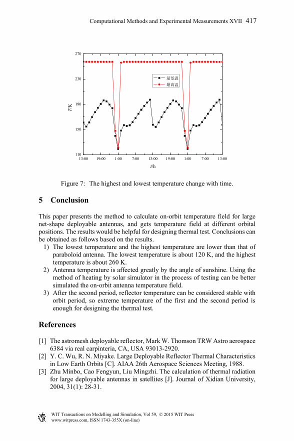
Figure 7 shows the highest temperature and lowest temperature of reflector vary with time during the first and second round period after satellite launched into the space. From the figure we found that the highest temperature changes slightly when antenna runs under sunshine. The temperature relates to optics properties. Difference between the highest temperature and lowest temperature is small when antenna runs under shadow, and the highest and lowest temperature all is about 120 K. On-orbit the lowest temperature is about 120 K to 200 K, which is lower than that of paraboloid antenna [9]. Based on calculation results, it is concluded that differences between temperature of end of the second period and that of end of the first period are very small, so after the second period reflector temperature can be considered stable with orbit period.
WIT Transactions on Modelling and Simulation, Vol 59, www.witpress.com, ISSN 1743-355X (on-line)
© 2015 WIT Press
416 Computational Methods and Experimental Measurements XVII
13:00 19:00 1:00 7:00 13:00 19:00 1:00 7:00 13:00110
150
190
230
270
T/K
t/h
最低温
最高温
Figure 7: The highest and lowest temperature change with time.
5 Conclusion
This paper presents the method to calculate on-orbit temperature field for large net-shape deployable antennas, and gets temperature field at different orbital positions. The results would be helpful for designing thermal test. Conclusions can be obtained as follows based on the results.
1) The lowest temperature and the highest temperature are lower than that of paraboloid antenna. The lowest temperature is about 120 K, and the highest temperature is about 260 K.
2) Antenna temperature is affected greatly by the angle of sunshine. Using the method of heating by solar simulator in the process of testing can be better simulated the on-orbit antenna temperature field.
3) After the second period, reflector temperature can be considered stable with orbit period, so extreme temperature of the first and the second period is enough for designing the thermal test.
References
[1] The astromesh deployable reflector, Mark W. Thomson TRW Astro aerospace 6384 via real carpinteria, CA, USA 93013-2920.
[2] Y. C. Wu, R. N. Miyake. Large Deployable Reflector Thermal Characteristics in Low Earth Orbits [C]. AIAA 26th Aerospace Sciences Meeting, 1988.
[3] Zhu Minbo, Cao Fengyun, Liu Mingzhi. The calculation of thermal radiation for large deployable antennas in satellites [J]. Journal of Xidian University, 2004, 31(1): 28-31.
WIT Transactions on Modelling and Simulation, Vol 59, www.witpress.com, ISSN 1743-355X (on-line)
© 2015 WIT Press
Computational Methods and Experimental Measurements XVII 417
[4] Zhu Minbo. The research on thermal analysis for large deployable antennas in satellites [D]. Doctoral dissertation of Xidian University, 2007.
[5] Zhu Minbo, Liu Mingzhi, Xu Haiqiang. The precision of adjustment technique for deployable truss antenna reflector on orbit thermal environment [J]. Journal of Astronautics, 2007, 28(3): 727-766.
[6] Zhong Qi, Wen Yaopu, Li Guoqiang. Influences of near-earth thermal environment parameters on spacecraft temperature: a first review [J]. Spacecraft Engineering, 2007, 16(3): 74-77.
[7] Tao Wenquan. Numerical Heat Transfer [M]. Xian: Xian Jiaotong University Press, 2001.
[8] Huang Bencheng, Tong Jingyu. Space Environment Engineering [M]. Beijing: China Science and Technology Press, 2010.
[9] Ma Huitao, Li Jindong. Integrated thermal-structural analytical for space structure with large scale and complicated construction [J]. Journal of Astronautics, 2008, 29(2): 413-419.
WIT Transactions on Modelling and Simulation, Vol 59, www.witpress.com, ISSN 1743-355X (on-line)
© 2015 WIT Press
418 Computational Methods and Experimental Measurements XVII