on relay node placement and assignment for two-tiered wireless … on relay node placement... · on...
TRANSCRIPT
On Relay Node Placement and Assignmentfor Two-tiered Wireless Networks
Wenxuan Guo & Xinming Huang & Wenjing Lou &
Cao Liang
Published online: 29 March 2008# Springer Science + Business Media, LLC 2008
Abstract Wireless networks that operate on batteries areimposed with energy constraints and long distance commu-nications between nodes are not desirable. ImplementingRelay Nodes (RNs) can improve network capacity and savecommunication energy. A two-hop relay routing scheme isconsidered, in which the RNs are temporarily placed andhave energy constraints. This paper investigates a jointoptimization problem on Relay Node Placement (RNP) androute assignment for two-tiered wireless networks. Arecursive Weighted Clustering Binary Integer Programming(WCBIP) algorithm is proposed to maximize the totalnumber of information packets received at the Base Station(BS) during the network lifetime. We first present anoptimization algorithm based on Binary Integer Program-ming (BIP) for Relay Node Assignment (RNA) with thecurrent node locations. Subsequently, a weighted clusteringalgorithm is applied to move the RNs to the best locationsto best serve their respectively associated Edge Nodes(ENs). The algorithm has the complexity of O(2n). Thesimulation results show that the proposed algorithm hassignificantly better performance than the other two relay
placement schemes. Both theoretical analysis and practicaldesign procedures are also presented with details.
Keywords two-tiered wireless network .
optimal relayed path . packet reception rate . BIP.
relay node placement
1 Introduction
Wireless sensor networks have been used in a wide range ofapplications. As one example of disaster communications,spatially distributed temperature sensors in an ablaze forestcan provide critical information about fire distribution, whichhelps to control the fire diffuse. Another example can be foundon the farms. Farmers use transducers to gather informationabout environmental parameters in their greenhouses. In bothscenarios, EdgeNodes (ENs), such as sensors and transducers,are deployed at strategic positions with fixed sensing andtransmit power, thus they can sustain a fixed length of lifetime.In addition to the deployment of ENs, a Base Station (BS) isneedful to collect data from the sensing field. However, due togeographic reasons, sometimes the BS could only beestablished far away from the sensing field, resulting in verylow data reception rate if there is any. To address this problem,a small number of Relay Nodes (RNs), as energy-limited asENs, can be placed between the sensing field and the BS toforward data packets. Here we only consider two-hop relayrouting from ENs to the BS. It is assumed that the power ofRNs can be adjusted to amplify the faded signals receivedfrom ENs and forward it to the BS. Therefore, the ENs, RNs,and BS build up a two-tiered wireless network in suchapplications.
There is a renewed interest in research on relayedcommunication networks [4]. In this paper, we consider
Mobile Netw Appl (2008) 13:186–197DOI 10.1007/s11036-008-0027-7
W. Guo (*) :X. Huang :W. Lou :C. LiangDepartment of Electrical and Computer Engineering,Worcester Polytechnic Institute,100 Institute Rd,Worcester, MA 01609, USAe-mail: [email protected]
X. Huange-mail: [email protected]
W. Loue-mail: [email protected]
C. Liange-mail: [email protected]
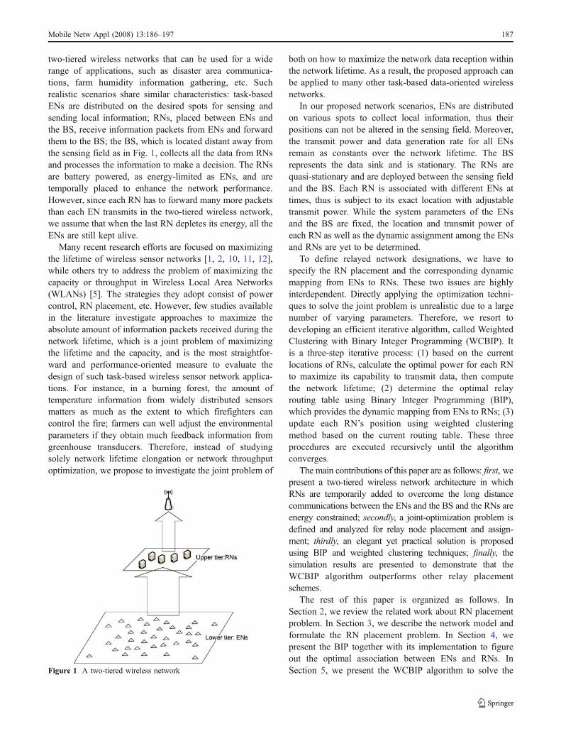
two-tiered wireless networks that can be used for a widerange of applications, such as disaster area communica-tions, farm humidity information gathering, etc. Suchrealistic scenarios share similar characteristics: task-basedENs are distributed on the desired spots for sensing andsending local information; RNs, placed between ENs andthe BS, receive information packets from ENs and forwardthem to the BS; the BS, which is located distant away fromthe sensing field as in Fig. 1, collects all the data from RNsand processes the information to make a decision. The RNsare battery powered, as energy-limited as ENs, and aretemporally placed to enhance the network performance.However, since each RN has to forward many more packetsthan each EN transmits in the two-tiered wireless network,we assume that when the last RN depletes its energy, all theENs are still kept alive.
Many recent research efforts are focused on maximizingthe lifetime of wireless sensor networks [1, 2, 10, 11, 12],while others try to address the problem of maximizing thecapacity or throughput in Wireless Local Area Networks(WLANs) [5]. The strategies they adopt consist of powercontrol, RN placement, etc. However, few studies availablein the literature investigate approaches to maximize theabsolute amount of information packets received during thenetwork lifetime, which is a joint problem of maximizingthe lifetime and the capacity, and is the most straightfor-ward and performance-oriented measure to evaluate thedesign of such task-based wireless sensor network applica-tions. For instance, in a burning forest, the amount oftemperature information from widely distributed sensorsmatters as much as the extent to which firefighters cancontrol the fire; farmers can well adjust the environmentalparameters if they obtain much feedback information fromgreenhouse transducers. Therefore, instead of studyingsolely network lifetime elongation or network throughputoptimization, we propose to investigate the joint problem of
both on how to maximize the network data reception withinthe network lifetime. As a result, the proposed approach canbe applied to many other task-based data-oriented wirelessnetworks.
In our proposed network scenarios, ENs are distributedon various spots to collect local information, thus theirpositions can not be altered in the sensing field. Moreover,the transmit power and data generation rate for all ENsremain as constants over the network lifetime. The BSrepresents the data sink and is stationary. The RNs arequasi-stationary and are deployed between the sensing fieldand the BS. Each RN is associated with different ENs attimes, thus is subject to its exact location with adjustabletransmit power. While the system parameters of the ENsand the BS are fixed, the location and transmit power ofeach RN as well as the dynamic assignment among the ENsand RNs are yet to be determined.
To define relayed network designations, we have tospecify the RN placement and the corresponding dynamicmapping from ENs to RNs. These two issues are highlyinterdependent. Directly applying the optimization techni-ques to solve the joint problem is unrealistic due to a largenumber of varying parameters. Therefore, we resort todeveloping an efficient iterative algorithm, called WeightedClustering with Binary Integer Programming (WCBIP). Itis a three-step iterative process: (1) based on the currentlocations of RNs, calculate the optimal power for each RNto maximize its capability to transmit data, then computethe network lifetime; (2) determine the optimal relayrouting table using Binary Integer Programming (BIP),which provides the dynamic mapping from ENs to RNs; (3)update each RN’s position using weighted clusteringmethod based on the current routing table. These threeprocedures are executed recursively until the algorithmconverges.
The main contributions of this paper are as follows: first, wepresent a two-tiered wireless network architecture in whichRNs are temporarily added to overcome the long distancecommunications between the ENs and the BS and the RNs areenergy constrained; secondly, a joint-optimization problem isdefined and analyzed for relay node placement and assign-ment; thirdly, an elegant yet practical solution is proposedusing BIP and weighted clustering techniques; finally, thesimulation results are presented to demonstrate that theWCBIP algorithm outperforms other relay placementschemes.
The rest of this paper is organized as follows. InSection 2, we review the related work about RN placementproblem. In Section 3, we describe the network model andformulate the RN placement problem. In Section 4, wepresent the BIP together with its implementation to figureout the optimal association between ENs and RNs. InSection 5, we present the WCBIP algorithm to solve theFigure 1 A two-tiered wireless network
Mobile Netw Appl (2008) 13:186–197 187

RN placement problem. The simulation results are demon-strated in Section 6, followed by conclusion in Section 7.
2 Related work
There are many researches focusing on the RN placementproblem for sensor wireless networks. In [2], a jointproblem of energy provisioning and relay node placementfor wireless sensor network is considered to maximize thenetwork lifetime. In [10], the authors seek to deploy aminimum number of relay nodes such that all the networknodes are connected, when sensor nodes and relay nodeshave different communication ranges. In [11], the problemto deploy a minimum number of relay nodes to guaranteeconnectivity of sensor nodes and the base station is studied.The network modeling also considers communication rangeof sensors and relay nodes. In [13], the relay nodeplacement problem in two-tiered wireless sensor networkis considered. The objective is to place minimum number ofrelay nodes to forward packets from sensor nodes to thesink. Likewise, communication ranges for sensor nodes andrelay nodes are also considered in the network modeling.Few papers focus on the amount of data reception at the BSduring the network lifetime.
Concerning techniques utilized in RN placement inwireless networks, many researches have done significantachievements that motivate us to pursue our goal. In [16],the optimal power is calculated for peer to peer communi-cation with respect to fixed Signal-to-Noise ratio. Besides,many heuristic and iterative approaches are employed tosolve the RN placement problems with different objectives.For example, A heuristic algorithm is presented in [8] forenergy provisioning and RN placement in wireless sensornetworks. In [5], an integer programming optimizationformulation and an iterative approach are proposed tocompute the best placement of a fixed number of RNs. In[14], a novel BIP formulation of the BS placement problemis proposed to find the optimal BS position in aninterference-limited indoor wireless system.
Not only in sensor network area, RNs have also beenused in cellular networks and WLAN. In [3], the iCARarchitecture is introduced to use RNs to redirect the cellularcommunication traffic from congested cell to its neighbor-ing cells. Another aspect of relay network applications iswireless LAN. Relay points [5] with access to power supplyare strategically placed to improve the throughput ofwireless LAN.
In [15], we studied the optimal relay association problemto maximize the data reception during the network lifetime.The RNs in the network scenario have fixed positions. Inthis paper, based on the previous work, we investigate theRN placement problem by iteratively moving the RNs to
“better” locations based on the optimal relay routingassignment of the current network scenario.
3 Network modeling and problem formulation
3.1 Network architecture
We focus on a two-tiered architecture for wireless sensornetworks. As shown in Fig. 1, there are three types of nodesin the network: ENs, RNs and the BS. ENs, constituting thelower tier of the network, are portable or quasi-stationaryuser terminals that are usually battery powered and areequipped with wireless transceivers. They could also below-bandwidth application-specific sensor devices. As ENsare responsible for collecting local task-based information,we assume that ENs are pre-deployed in the field atstrategic positions. The operation mode for ENs is verysimple: Once triggered by an event, each EN sends an F-bitpacket directly to a relay node in one hop per time periodusing a constant transmit power. Each EN may select adifferent path to BS by choosing a different RN from timeto time. Therefore, the ENs associated with each relay maychange over time. Since RNs are supposed to be energyconstraint, we assume that ENs keep alive before all theRNs die. It should also be noted here that because ENs arevery close to each other and the BS is far away from ENs,multi-hop routing among ENs is not necessary as it will notbring any distinct benefits to the data transmission.
The upper tier of a network is made up of RNs. Duringeach period, each RN simply forwards all packets receivedfrom ENs to the BS. RNs share equivalent receiving power,but differ with each other in the aspect of transmit power.Since RNs are deployed between ENs and the BS, and areassociated with different ENs during the network lifetime,their optimal locations are subject to the distribution of ENsand location of the BS to yield the best performance.Suppose their initial energy levels are the same, RNs maydeplete their energy at different time because of differenttraffic load and transmit power. When one RN runs out itsenergy, the ENs associated with this RN in the previousperiod may switch to another RN to send packets in thenext period. Here we also disregard multi-hop datatransmission among RNs, because the transmit power ofRNs are adjustable to amplify the signals to reach the BS.Moreover, as it is easily understood that more RNs wouldachieve a larger amount of packets received at the BS, afixed and moderate number of RNs are introduced in thisnetwork model.
The data sink in a two-tiered wireless network is the BS.As the BS collects all information packets forwarded by theRNs from the ENs, it is assumed that the BS has sufficientenergy provided by a large or constantly reprovisioned
188 Mobile Netw Appl (2008) 13:186–197

battery source. It is also assumed that the BS has a fixedposition as an information gathering center.
3.2 Joint problem of RN placement and assignment
As an ultimate goal, RNs should be placed in locationsresulting in the largest amount of data reception at the BSwithin the network lifetime. For a two-tiered wirelessnetwork with every node placed at certain fixed position,the optimal association between ENs and RNs needs to becomputed such that the amount of correct packets receivedat the BS is maximized. It is obvious that different networktopologies could yield different maximized amount of datareception. Then for a network with a BS, a group of ENs,and a given number of RNs waiting to be deployed, thequestion becomes: where should we place these RNs andwhat are the optimal associations between ENs and RNs,such that the total amount of correct packets received at theBS during the network lifetime is maximized?
From the above analysis, we can see that the two issuesof RN placement and the corresponding dynamic mappingfrom ENs to RNs are highly interdependent. As we aredesirous of finding the optimal RN placement, we shouldalso consider the corresponding association between ENsand RNs for the node locations as well as the maximizedamount of data received at the BS.
In the definition of system objective and constraintfunctions, Table 1 contains all adopted conventions.
Since packets are transmitted through a two-hop trans-mission, the total number of correct packets received at theBS would be
Pni¼1
Pmj¼1
PTt¼1
PRR ei; rj� �
PRR rj;BS� �
xtij.
RNA problem For a two-tiered wireless network, e ¼e1; e2; :::enf g are placed at ei x; yð Þ i ¼ 1; 2:::nð Þ; r ¼r1; r2; :::rmf g are placed at rj x; yð Þ j ¼ 1; 2:::mð Þ; the BS is
placed at s x; yð Þ;
maxXni¼1
Xmj¼1
XTt¼1
PRR ei; rj� �
PRR rj;BS� �
xtij
s:t: Xmj¼1
xtij ¼ 1
Xni¼1
XTt¼1
xtij � buffer jð Þ
RNP problem Given a deployment of ENs and one BS,find the positions for a fixed number of RNs, such that themaximum number of correct packets from ENs can bereceived at the BS.
4 Technical approach for RNA
In this section, we present a BIP method based on powercontrol for RNA problem. Given a two-tiered topology withknown locations of all nodes, we can calculate the optimalpower for all the RNs and compute the network lifetime.Then we can obtain two constraints and adopt the BIPmethod with the constraints to find a solution for RNAproblem under current network deployment.
4.1 Optimal power control for RNs
4.1.1 Path loss model
The RNA solution depends heavily on the relationshipbetween transmit power and packet error rate, which can bemodeled using path loss channel model in physical layer. Inthis paper, the following path loss model is used.
P0dα0 ¼ P1d
α1 ð1Þ
where P0 and P1 are the signal power measured at d0 andd1 meters away from the transmitter, respectively. α denotesthe path loss exponent. If we set d0 to be 1 meter, thus P0
is the reference signal power measured at 1 meter awayfrom the transmitter. Then Eq. 1 is simplified as P1 ¼ P0
da1. Pa
can be calculated using the free space propagation model as:
P0 ¼ GtGrl4p
� �2
�Pt ð2Þ
Where Pt is the transmit power, Gt and Gr are thetransmitter and receiver antenna gains respectively, 1 ¼ c=f
Table 1 Notation
Symbol Definition
{e1,e2,…en} The set of ENsei(x,y) The XY location of ei{r1,r2,…rm} The set of RNsrj(x,y) The XY location of ris(x,y) The XY location of BSPRR (a, b) Packet reception rate (PRR) between
node a and node bT Network lifetime in periodsXij Number of times that ei sends packets
to rj during the network lifetime Tperiods
xtij If ei sends data to rj in the tth period,xtij ¼ 1; else xtij ¼ 0
buffer (j) Number of packets that rj can transmit;Ptj Transmit power of rjNtotal Total number of packets received within
network lifetime
Mobile Netw Appl (2008) 13:186–197 189

is the wavelength of the transmitted signal, and c is thevelocity of radio-wave propagation in free space, which isequal to the speed of light.
Then the received power Pr at a distance d meters awayfrom the transmitter can be calculated as:
Pr ¼GtGr
λ4π
� �2�Pt
dαð3Þ
Suppose Pnoise denotes the power of noise, then the signal-to-noise ratio (SNR) at the receiver end is:
SNR ¼ Pr
Pnoiseð4Þ
The bit error rate can be determined by the SNR basedon the error probability model. For illustration purpose, wetake BPSK [6] as the modulation scheme and the bit errorrate is given by
Pb ¼ 1
2e�
12SNR ð5Þ
Assuming bit error rate occurs independently, the packetreception rate (PRR) is
PRR ¼ 1� Pbð ÞF¼ 1� 1
2e�
12SNR
� �F
ð6Þ
where F is the packet size.
4.1.2 Optimal power control
Considering a peer-to-peer communication between a relayri and the BS, there is a certain distance di between ri andthe BS. We assume ri uses transmit power Pti, and it relayszti packets to the BS in time period t, or there are zti ENssending packets to ri in the tth period. Using above-mentioned error probability model, the total number ofpackets that the BS receives from ri is:
Mi ¼XTt¼1
zti 1� 1
2e�ρ
Ptidαi
� �F
ð7Þ
where r ¼ 12 GtGr
c4pf
� �21
Pnoiseand T is the overall number of
periods, also referred as the relay network lifetime. Thetotal number of packets that can be transmitted by ri isrestricted by its energy. Then we have:
XTt¼1
zti ¼E � v
Pti þ Pelecð ÞF ð8Þ
where E denotes the total energy each RN holds, v is thetransmission bit rate, Pelec denotes the electronic powerconsumed by receiving one packet.
Combining Eqs. 7 and 8 yields:
Mi ¼ E � vPti þ Pelecð ÞF � 1� 1
2e�r
Ptidai
� �F
ð9Þ
To maximize Mi, we need to find the optimum power Pti.Take a derivative of Mi with respect to Pti, and set thederivative to zero, we get the following characteristicequation from convex theory:
1
2Pti þ Pelecð Þ � F � e�rPti
dai � r
daiþ 1
2e�rPti
dai � 1 ¼ 0 ð10Þ
Let us set Ω to be the collection of all solutions to Eq. 10.By optimization theory, the optimal point Pt�i maximizingthe function Mi(Pti) must lie in the union of the set Ω andboundary points of Pti. Note that Eq. 10 is transcendentaland may not have closed form solutions. Numericalsolutions for an experimental setup will be provided inSection 5.
4.2 Fixed relay network lifetime
Based on the analysis above, each RN has an optimaltransmit power Pt�i setup for best energy efficiency. Giventhe total energy constraint E, the total number of packetsthat ri can relay is:
buffer ið Þ ¼ E � vPt�i þ Pelecð ÞF ð11Þ
Relay network lifetime is defined as the total number ofnetwork operating periods, represented by T. The totalnumber of packets received from ENs equals to the totalnumber of packets forwarded by all RNs. Thus,
T ¼ 1
n
Xmi¼1
E � vPt�i þ Pelecð ÞF ð12Þ
Where m denotes the number of RNs and n denotes thenumber of ENs. For ri with fixed location in a two-tieredwireless network, Pt�i can be determined from Eq. 10.Therefore, the relay network lifetime T is fixed if the energylevels of RNs are known.
4.3 BIP optimization
4.3.1 Description of BIP optimization
BIP optimization is a linear programming (LP)-basedbranch-and-bound algorithm. The algorithm searches foran optimal solution to the BIP problem by solving a series
190 Mobile Netw Appl (2008) 13:186–197

of LP-relaxation problems. The branch-and-bound methodis described briefly below. More details can be referred to[7].
The algorithm creates a search tree by repeatedly addingconstraints to the problem, called “branching.” At abranching step, the algorithm chooses a variable xj whosecurrent value is not an integer and adds the constraint xj=0to form one branch and the constraint xj=1 to form theother branch. This process can be represented by a binarytree, in which the nodes represent the added constraints.
At each node, the algorithm solves the LP-relaxationproblem using the constraints at that node and decideswhether to branch or to move to another node depending onthe outcome. There are three possibilities: (1) If the LP-relaxation problem at the current node is infeasible or itsoptimal value is greater than that of the best integer point,the algorithm removes the node from the tree, after which itdoes not search any branches below that node. Thealgorithm then moves to a new node according to the pre-specified method. (2) If the algorithm finds a new feasibleinteger point with lower objective value than that of thebest integer point, it updates the current best integer pointand moves to the next node. (3) If the LP-relaxationproblem’s optimal value is not an integer and the optimalobjective value of the LP relaxation problem is less than thebest integer point, the algorithm branches below this node.
As the algorithm could potentially search all 2n binaryinteger vectors, the running time for BIP is O(2n). n is thenumber of variables that need to be specified. As futurework, we can transform the Binary Integer Programmingproblem into a linear optimal distribution problem [18] bygenerating a directed graph, to reduce the computationcomplexity to only O(n3).
4.3.2 Optimizing the RNA Problem
Suppose the PRR from ri to the BS is Ri, then the totalnumber of packets received correctly at the BS can bepresented as:
Ntotal ¼Xni¼1
Xmj¼1
XTt¼1
PRR ei; rj� �
PRR rj;BS� �
xtij ð13Þ
The constraints are listed in Eqs. 14 and 15: (1) ei associateswith one RN in one period; (2) the total packets sent to rjcan not exceed the buffer size of rj.Xmj¼1
xtij ¼ 1 i ¼ 1; 2::::n; t ¼ 1; 2:::Tð Þ ð14Þ
Xni¼1
Xij � buffer jð Þ j ¼ 1; 2; :::mð Þ ð15Þ
In practice, we define the coefficient vector as:f ¼ ½Y1;Y2; :::;Yn� ð16Þ
Yi ¼ QiQi:::Qi½ �|fflfflfflfflfflfflffl{zfflfflfflfflfflfflffl}T
; i ¼ 1; 2; :::n ð17Þ
Qi ¼ PRR ei; r1ð ÞPRR r1;BSð Þ; :::;PRR ei; rmð ÞPRR rm;BSð Þ½ �;i ¼ 1; 2; :::; n ð18Þ
The solution vector is given as:
U ¼ ½S1; S2; :::; Sn� ð19Þ
Si ¼ Ki1;Ki2; :::KiT½ �; i ¼ 1; 2; :::; n ð20Þ
Kij ¼ xji1; xji2; :::x
jim
; j ¼ 1; 2; :::; T ð21Þ
where xtij can only take the values of 0 or 1, and xtij ¼ 1means ei send one packet to ri during the tth periodindicated by the superscript.
To implement equality constraint, we define the coeffi-cient matrix Aeq as in Eq. 22 and the result vector beq as inEq. 23.
Aeq ¼
111:::11|fflfflfflffl{zfflfflfflffl}m
j000:::00|fflfflfflffl{zfflfflfflffl}m
j000::00j::::::::::j000:::00
000:::00j111:::11|fflfflfflffl{zfflfflfflffl}m
j000:::00|fflfflfflffl{zfflfflfflffl}m
j:::::::::j000:::00
000:::00j000::00j111:::11|fflfflfflffl{zfflfflfflffl}m
j::::::::::j000:::00::::::::::::::000::00j000:::00|fflfflfflffl{zfflfflfflffl}
m
j::::::j000::::000j111:::11|fflfflfflffl{zfflfflfflffl}m
266666666664
377777777775
ð22Þ
beq ¼ ð1; 1; 1; :::1ÞT ð23ÞWhere Aeq is n×T by m×n×T matrix and beq is vector withlength m×n×T.
Similarly, we define the coefficient matrix A and theresult vector b as in Eqs. 24 and 25, respectively, in order toimplement the inequality constraint.
A ¼
100:::00|fflfflfflffl{zfflfflfflffl}m
j100:::00|fflfflfflffl{zfflfflfflffl}m
j100::00j::::::::::j100:::00
010:::00j010:::00|fflfflfflffl{zfflfflfflffl}m
j010:::00|fflfflfflffl{zfflfflfflffl}m
j:::::::::j010:::00
001:::00j001::00j001:::00|fflfflfflffl{zfflfflfflffl}m
j::::::::::j001:::00::::::::::::::000::01j000:::01|fflfflfflffl{zfflfflfflffl}
m
j000::::01j:::::::::j000:::01|fflfflfflffl{zfflfflfflffl}m
266666666664
377777777775
ð24Þ
Mobile Netw Appl (2008) 13:186–197 191

where Aeq is m by m×n×T matrix.
b ¼ ðbufferð1Þ; bufferð2Þ; ::::bufferðmÞÞT ð25Þ
Then the RNA problem can be redefined as in the formbelow:
maximize f � UT such that A� UT � b;Aeq � UT ¼ beq
ð26Þ
5 WCBIP: an iterative approach for RNP
In this section, we first provide an analysis on how tomaximize the amount of correct data reception with respectto different relay node placements. Then the analysis resultsare used to bring forward an efficient algorithm calledWCBIP.
5.1 Analysis on RNP problem
Section 4 gives a detailed description on how to assignENs to RNs within a fixed scenario, such that the amountof correct packets received at the BS can be maximized.Each relay node functions as a cluster head to forwardpackets from its cluster members. As we observe this two-tiered network system in this cluster view, maximizing thetotal number of correct packets received at the BS istantamount to maximizing performance of each cluster.Because within the current network scenario, the ENs are
immobile while the RNs are temporarily placed. Intuitive-ly, we construct the clustering function for relay node rjas:
fcluster�j ¼Xni¼1
Xij
buffer jð Þ PRRðei;rjÞPRRðrj;BSÞ
¼Xni¼1
Xij
buffer jð Þ 1� 1
2e�ρ
Ptedgedαij
!F
1� 1
2e�ρ
Ptidαj
� �F
ð27Þ
where Ptedge denotes the constant transmit power of ENs.dij represents the distance between edge node ei and relaynode rj. fcluste-j is a function of the x–y location of relaynode rj. The weighted factor Xij
buffer jð Þ denotes the contribu-tion each edge node makes to the overall clusterperformance. As we move rj, we can search for theposition where the clustering function reaches its maximalvalue.
5.2 Implementation of WCBIP
Based on the relay placement analysis, we propose aniterative procedure to search for the optimal positions of allRNs so that the maximum amount of correct packets can bereceived at the BS.
Step 1: Initial placement. According to the EN deployment,RNs are evenly distributed within the coverage area.
Step 2: Obtaining two constraints for BIP. Calculate optimalpower for each RN and compute the networklifetime;
WCBIP algorithm: 1. Initialization: evenly distribute RNs; 2. Compute the optimal power for each RN; 3. Calculate the network lifetime in periods; 4. Apply BIP method with two constraints to find a solution χ to RNA; 5. The total number of correct packets received at the BS at this optimal point is totalN ; 6. Set iterations=1, nonincrease=0 ; 7. While( iterations M< thC< ){ 8. for (j=1; j<No. of RNs ; j=j+1) { 9. Construct cluster jf – ;
10. update ( , )jr x y to maximize cluster jf – ;}
Compute the optimal power for each RN;Calculate the network lifetime in periods;
13. Apply BIP method with two constraints to find a solution newχ to RNA; 14. The total number of correct packets received at the BS at this optimal point is total newN – ;
If ( total new totalN N– < = ) { 16. nonincrease=nonincrease+1; 17. else nonincrease=0 ; } 18. total total newN N –= ;
19. iterations=iterations+1; } Output newχ and total newN – ; Task ends.
and nonincrease
20.
11.12.
15.
21.
Figure 2 Pseudo code of theWCBIP algorithm
192 Mobile Netw Appl (2008) 13:186–197

Step 3: BIP optimization for RNA. With respect tocurrent node locations (the positions of ENs,RNs and the BS), BIP is applied to obtain theRNs’ assignment result and the total number ofcorrect packets received at the BS at this optimalpoint is Ntotal.
Step 4: Setting RNs to new positions. According to theassignment result, for each relay node rj, constructthe clustering function fcluste-j, as a function ofrj(x,y). Search for the maximal value of fcluste-j,move rj to the new position.
Step 5: Iteration and termination. The algorithm termi-nates when any one of the following conditionsare true:
a. M iterations are completed.b. Ntotal has not increase for Cth consecutive times.
Otherwise, the procedure goes back to Step 2. Thepseudo code is shown as in Fig. 2.
6 Simulation results
6.1 Experimental study on RNA problem
6.1.1 Experiment parameters
For experimental setup, we establish the network scenarioas follows: ten ENs are randomly distributed within onesixth of circles with their center located at (0, 0), and radiusvarying between [40, 50]; the RNs, with the equal radiansbetween each other, are also placed within the same set ofconcentric circles with their radius at 30. The BS is placedat XY coordinate (10, 0), as shown in Fig. 3.
The assumptions and experimental parameters are: unitgain for both the transmitter and receiving antenna; thefrequency of the electromagnetic signal is 2.4 GHz; the noisepower is 2.15×10⁻¹⁰ W; the electronic power for receivingone packet is 2.53×10⁻² W; the size of one packet is 80 bits;the ENs each use a constant transmit power of 10−2 W; therate with which the RNs send data is 11Mb/s [8]; the totalenergy for one relay node is 5×10⁻⁵ J (we render the energyof RNs so small for simulation purpose).
6.1.2 The optimal power of RNs
Given the fixed positions of the RNs and the BS, we candraw the number of packets that ri can forward withdifferent transmit power based on Eq. 10. Transmission atthe optimal power provides the best energy efficiency forthe RNs.
As shown in Fig. 4, for each relay node, the optimaltransmit power can be obtained at the peak point. It can alsobe observed that the optimal transmit power is larger if therelay is further away from the BS.
Figure 3 A scenario setup to show network nodes geographicpositions
10-3
10-2
10-1
100
0
50
100
150
200
Transmit power(watts)
Cor
rect
pac
kets
rec
eive
d fr
om r
i
relay node 1relay node 2relay node 3relay node 4relay node 5
Figure 4 Total number of packets correctly received at the BS fromrelays using different transmit power
10 15 20 25 30 35 40600
620
640
660
680
700
720
740
760
780
800
the number of edge nodes
the
num
ber
of c
orre
ct p
acke
ts r
ecei
ved
BIPNearest-AssignCluster-Based-Assign
Figure 5 The number of correct packets received using three differentassignments
Mobile Netw Appl (2008) 13:186–197 193

6.1.3 Comparison of the proposed methodand other assignment schemes
To demonstrate the advantages of the proposed method, wecompare it with two other assignment schemes under thecurrent network topology. One scheme is called the nearestrelay assignment method [17], based on which every edgenode sends its packets to the nearest active relay node. Theother scheme requires that all RNs manage their members(ENs) as cluster heads [2]. The RNs are assigned ENsaccording to their capacity. Technically, the number of ENsassigned to ri is in inverse proportion to Pt�i þ Pelec
� �based
on the energy constraint as in Eq. 9. Figure 5 shows theperformance of these three methods when the number ofENs varies from 10 to 40.
For each experimental setup, the locations of ENs areplaced almost randomly. Therefore, the packet receptionrates from ENs to RNs change. The number of packets
correctly received at BS varies. But for any givenexperimental cases, Fig. 5 clearly shows that the BIPmethod results significantly more information packetsreceived at the BS than the other two techniques.
Table 2 lists the assignment results of these threemethods for the case of ten ENs. Each row denotes anedge node, and each column corresponds to a relay node.The numbers in the table represent the number of periodsduring which the edge node selects the relay node toforward its packets.
6.2 Experimental study on WCBIP for RNP problem
The BIP method can be used to find the fixed relay schemeto maximize the number of correct packets received at theBS. The WCBIP method incorporates the BIP for eachrelay as part of iteration, and in every iteration searches fora “better” location to improve the value of each clustering
Table 2 Assignment results of three methods for ten ENs
Our work(BIP) Nearest-relay-assign [17] Cluster-based-assign [2]
r1 r2 r3 r4 r5 r1 r2 r3 r4 r5 r1 r2 r3 r4 r5
e1 0 21 65 0 0 0 70 0 7 7 86 0 0 0 0e2 86 0 0 0 0 61 9 0 7 7 0 0 0 0 86e3 13 73 0 0 0 61 9 0 7 7 86 0 0 0 0e4 0 0 23 63 0 0 0 58 19 7 0 86 0 0 0e5 86 0 0 0 0 61 9 0 7 7 0 0 0 0 86e6 0 0 0 16 70 0 0 0 77 7 0 0 86 0 0e7 0 0 0 0 86 0 0 0 0 84 0 0 0 86 0e8 0 86 0 0 0 0 70 0 7 7 0 86 0 0 0e9 0 0 86 0 0 0 12 58 7 7 0 0 0 86 0e10 0 0 0 86 0 0 0 58 19 7 0 0 86 0 0
Figure 6 Network scenario at convergence using WCBIPFigure 7 Iterations vs. Total number of received packets for threeweighted clustering-based methods
194 Mobile Netw Appl (2008) 13:186–197

function. The search function we choose is the simplexsearch method [9], as one kind of unconstrained nonlinearoptimization. In our simulations, we adopt the fminsearchfunction in Matlab to implement this optimization method.
As an example, using WCBIP (here we change theenergy level for RNs to 2 × 10⁻⁵ J), the network scenario isinitialized as Fig. 3 and the ultimate deployment of RNs isshown in Fig. 6. The total number of correct packetsreceived at each iteration is demonstrated in Fig. 7. Todemonstrate its advantage, we also adopt the other twomethods, called as weighted clustering (WC) nearest assignand weighted clustering (WC) cluster-based assign. As theyare named, these methods update the placement of RNssimilarly as WCBIP, but based on their own associationtables. For WCBIP, the number of correct packets receivedincreases greatly after the first iteration, followed by smallimprovement in the next a few iterations. This is becausethe first iteration has already moved each relay node close
to its optimal place. As shown in Fig. 7, WCBIP algorithmhas the advantage of quick convergence with significantperformance improvement. In contrary, results for the othertwo methods remain much lower.
We also consider the impact that the range of ENs inradian has on the data reception performance. From Fig. 8,we can see the total number of packets received increases asthe number of RNs increases. This is because more RNsinduce more energy to transmit data. Besides, as the radianof range increases, the number of packets received at theBS decreases slightly. The reason is that with a larger range,every packet would travel longer distances thus decreasesits own reception rate.
To demonstrate the relationship between ENs’ locationsand the number of packets received, we set up anothernetwork scenario as follows: 20 ENs are evenly distributedon one sixth of a circle with its center located at (0, 0), andradius changing. The BS is placed at XY coordinate (0, 0).
Figure 8 Number of received packets with respect to differentRanges of ENs in radian and number of RNs
Table 3 RN placements with respect to different EN locations
Distance to BS (meters) RN’s final placements
r1 r2 r3 r4 r5
35 (4.9, 1.2) (6.4, 0.8) (5.8, 3.6) (3.4, 3.0) (4.7, 5.2)40 (8.4, 0.6) (8.1, 2.4) (7.3, 4.0) (6.6, 5.6) (5.1, 6.6)45 (12.2, 3.6) (12.4, 1.0) (11.1, 6.0) (9.6, 8.2) (7.5, 10.0)50 (17.0, 1.4) (16.5, 4.9) (15.2, 8.1) (13.1, 11.1) (10.5, 13.6)55 (21.8, 1.7) (21.1, 6.3) (19.4, 10.6) (16.6, 14.2) (13.3, 17.2)60 (26.7, 2.1) (25.9, 7.6) (23.4, 12.6) (20.3, 17.4) (16.4, 21.3)65 (31.6, 2.5) (30.7, 9.1) (28.0, 15.1) (24.5, 20.8) (19.4, 25.1)70 (37.0, 2.8) (35.5, 10.5) (32.5, 17.7) (28.1, 24.0) (22.7, 29.6)
Figure 9 Correct packets received with respect to the distancebetween ENs and the BS
Mobile Netw Appl (2008) 13:186–197 195

We employ the WCBIP method to place five RNs betweenthe BS and ENs. The placement results are shown inTable 3. Each of the dual numbers represents the XY-location of the corresponding RN when ENs are placed atthe corresponding distance away from the BS. As can beseen from the table, the RNs’ positions become furtheraway from the BS as the ENs are placed at a larger distanceaway. Figure 9 depicts the number of correct packetsreceived with respect to WCBIP and direct transmissionfrom ENs to the BS without data relay when ENs areplaced at different distances away from the BS. From Fig.9, it can be seen that introducing a tire of RNs increases thenumber of packets received. Although results for bothmethods decreases as the ENs are placed further away fromthe BS, the number of packets received through directtransmission goes down much more rapidly than the casethat RNs are placed with WCBIP to help forward packetsfrom ENs.
7 Conclusion
In this paper, we investigate the joint problem of RNA andRNP for two-tiered wireless sensor networks. Since thesetwo problems are highly interdependent, we developed anefficient iterative algorithm, called as WCBIP to find theoptimal the RN placement to maximize the data received atthe BS within a network lifetime. This approach firstlyderives the optimal transmit power for each RN as well asthe fixed relay network lifetime. Subsequently, we deter-mine the dynamic optimal RNA in every period using BIPsuch that the BS receives the maximum number of effectiveinformation packets. Then we update each RN’s position byoptimizing their data transmission performance undercurrent assignment results using a weighted clusteringmethod. These three steps are executed iteratively untilthe algorithm converges. Experimental results show thatwithin a fixed network scenario, the proposed BIP methodyields much better performance than the other two schemes,nearest relay assignment and cluster-based assignment. Thesimulation results demonstrate that RNs can send the mostinformation packets when taking the optimal transmitpower. Moreover, we observe that WCBIP convergeswithin a few steps, yielding better results than other twoweighted clustering methods and direct data transmissionfrom ENs to the BS. Finally, we quantify the effects of ENlocations, with respect to angle and distance from the BS,on RNP and the maximum number of information packetsreceived.
For future work, we will pursue the following directions:relaxing the constraints on network energy model of edge
nodes and relay nodes; extending our algorithm such that itcan be applied to a multi-tiered multi-hop network;reducing the complexity by transforming the BIP-basedmethod to a low-cost approach, such as the Linear OptimalDistribution method [18].
References
1. Xin Y, Guven T, Shayman M (2006) Relay deployment and powercontrol for lifetime elongation in sensor networks. Presented atProceedings of IEEE ICC
2. Hou Y, Shi Y, Sherali H, Midkiff S (2005) On energy provisioningand relay node placement for wireless sensor networks. IEEETrans Wireless Commun 4:2579–2590
3. Wu H, Qiao C, De S, Tonguz O (2001) Integrated cellular and adhoc relaying systems: iCAR. IEEE J Sel Areas Commun19:2105–2115
4. Wei H, Gitlin R (2004) Two-hop-relay architecture for next-generation WWAN/WLAN integration. IEEE Trans WirelessCommun 11:24–30
5. So A, Liang B (2007) Enhancing WLAN capacity by strategicplacement of tetherless relay points. IEEE Trans Mobile Comput6:522–535
6. Proakis J (1995) Digital communications, 3rd edn. McGraw-Hill,New York
7. Wolsey L (1998) Integer programming. Wiley, New York8. Anastasi G, Borgia E, Conti M, Gregori E, Passarella A (2005)
Understanding the real behavior of Mote and 802.11 ad hocnetworks: an experimental approach. Pervasive Mobile Comput1:237–256
9. Lagarias J, Reeds J, Wright M, Wright P (1998) Convergenceproperties of the Nelder–Mead simplex method in low dimen-sions. SIAM J Optim 9(1):112–147
10. Lloyd E, Xue G (20007) Relay node Placement in WirelessSensor Networks. IEEE Trans Comput 56(1):134–138
11. Wang Q, Xu K, Takahara G, Hassanein H (2005) Locally optimalrelay node placement in heterogeneous wireless sensor networks.In: Proceedings of IEEE GLOBECOM, pp 2549–3553
12. Himson T, Pam W, Han Z, Liu K (2007) Lifetime maximizationvia cooperative nodes and relay deployment in wireless networks.IEEE J Sel Areas Commun 25(2):306–317
13. Liu H, Wang P, Jia X (2006) On optimal placement of RNs forreliable connectivity in wireless sensor networks. J Comb Optim11:249–260
14. Wong J, Mason A, Neve M, Sowerby K (2006) BS placement inindoor wireless systems using BIP. IEEE Proc Commun 153(5):771–778
15. Guo W, Huang X (2007) Relaying packets in a two-tiered wirelessnetwork using BIP. In: Proceeding of WASA’07, pp 254–259
16. Li C, Hsu W, Krishnamachari B, Helmy A (2006) A local metricfor geographic routing with power control in wireless networks. InProceedings of Secon
17. Sadek AK, Han Z, Liu K (2006) A distributed relay-assignmentalgorithm for cooperative communications in wireless networks.In: Proceedings of the IEEE Conference on Communications, vol4, pp 1592–1597
18. Li G, Liu H (2006) Resource allocation for OFDMA relaynetworks with fairness constraints. IEEE J Sel Areas Commun 24(11):2061–2069
196 Mobile Netw Appl (2008) 13:186–197

Wenxuan Guo received the B.S.degree in computer science andtechnology and the M.S. degreesin information security fromHuazhong University of Scienceand Technology, Wuhan, China in2004 and 2007, respectively. He iscurrently a Ph.D. student in Elec-trical and Computer Engineeringat Worcester Polytechnic Institute,Worcester, MA. His research in-terest is optimization of wirelessnetworks.
Xinming Huang received the B.S.and the M.S. degrees from North-western Polytechnic University,Xi’an, China in 1994 and 1996respectively, and a Ph.D. degree inelectrical engineering from Vir-ginia Tech, Blacksburg, VA in2001. He is currently an AssistantProfessor in the Department ofElectrical and Computer Engineer-ing at Worcester Polytechnic Insti-tute, Worcester, MA. He previouslyworked at the wireless advancedtechnology laboratory, Bell Labs ofLucent Technologies. His research
interests are in circuits and systems design for embedded computing,including computer architectures, reconfigurable computing, embed-ded systems, and wireless networks.
Wenjing Lou obtained her Ph.D.degree in Electrical and ComputerEngineering from University ofFlorida in 2003. She received theM.A.Sc degree from NanyangTechnological University, Singa-pore, in 1998, the M.E degree andthe B.E degree in Computer Sci-ence and Engineering from Xi’anJiaotong University, China, in 1996and 1993, respectively. From De-cember 1997 to July 1999, sheworked as a Research Engineer inNetwork Technology Research
Center, Nanyang Technological University. She joined the Electricaland Computer Engineering department at Worcester PolytechnicInstitute in 2003 as an assistant professor. Her current researchinterests are in the areas of ad hoc, sensor, and mesh networks, withemphases on network security and routing issues. She was namedJoseph Samuel Satin Distinguished fellow in 2006 by WPI. She is arecipient of the US National Science Foundation Faculty Early CareerDevelopment (CAREER) award in 2008.
Cao Liang received the B.S degreein Communication and InformationEngineering from University ofElectronic Science and Technologyof China, Chengdu, China, 2001,the M.S. degree in electrical engi-neering from University of NewOrleans, New Orleans, LA, in2006. He is currently working to-ward the Ph.D. degree in Electricaland Computer Engineering atWorcester Polytechnic Institute,MA. His research interests includehigh performance computing archi-
tecture design, VLSI design, reconfigurable systems, and routing incollaborative computing networks.
Mobile Netw Appl (2008) 13:186–197 197