on the electric effect of rotating a dielectric in a magnetic field
DESCRIPTION
H.A. WilsonTRANSCRIPT
On the Electric Effect of Rotating a Dielectric in a Magnetic FieldAuthor(s): Harold A. WilsonSource: Philosophical Transactions of the Royal Society of London. Series A, Containing Papersof a Mathematical or Physical Character, Vol. 204 (1905), pp. 121-137Published by: The Royal SocietyStable URL: http://www.jstor.org/stable/90913 .
Accessed: 04/05/2014 14:34
Your use of the JSTOR archive indicates your acceptance of the Terms & Conditions of Use, available at .http://www.jstor.org/page/info/about/policies/terms.jsp
.JSTOR is a not-for-profit service that helps scholars, researchers, and students discover, use, and build upon a wide range ofcontent in a trusted digital archive. We use information technology and tools to increase productivity and facilitate new formsof scholarship. For more information about JSTOR, please contact [email protected].
.
The Royal Society is collaborating with JSTOR to digitize, preserve and extend access to PhilosophicalTransactions of the Royal Society of London. Series A, Containing Papers of a Mathematical or PhysicalCharacter.
http://www.jstor.org
This content downloaded from 130.132.123.28 on Sun, 4 May 2014 14:34:57 PMAll use subject to JSTOR Terms and Conditions
r I21 ]
III. On the Electric Ef#ct olf Rotatiqn a Dielectric in a Magnetic Fiell.
By HAROLD A. AWILSON, iMA., D.Sc., Fellowv of Trinity College, Cambridge.
Covm mutni cated by I tPofessor J. J. TH OMSON, F.R.S.
Received"May 18,-Read June 2, 1904.
IT was shown by FARADAY in 1831 that an electromotive force is induced in a conductor moving in a magnetic field so as to cut the lines of magnetic force. The
object of the experiments described in the present paper was to see if a similar effect exists iin a dielectric when it imoves in a magnetic field, and to measure the amount of the effect if it were found to exist.
According to MAXWEULL'S electrodynamic theory, as developed by H. A. LORENTZ
and by LARMOR, suchl anl electromotive force should be produced in a dielectric, and should be equal to thle electromotive force inl a conductor multiplied by the factor 1 - K-', where K is the specific inductive capacity of the dielectric.
It appears, from the experinmentts described below, that the effect in question does
exist, and is very nearly of the amount predicted by the theory. The experiments, therefore, may be regarded as a confirmation of the theory in question.
The paper is divided into the following parts :-
(1) Theory of the experiment; (2) description of apparatus; (3) method of
experimenting and results obtained; (4) comparison of the results with
theory; (5) summary of results and conclusion.
(1.) Theory of the Experim,ient.
In FARADAY'S original experiment a metal disk was placed in a magnetic field
perpendicular to the plane of the disk, and the axle of the disk and its circumference were connlected by sliding contacts to a galvanometer. When the disk was rotated, a current passed through the galvanometer, showing that an electromotive force was induced in the disk by its motion in the magnetic field.
The method I have used is very anialogous to that employed by FARADAY. A hollow cylinder of dielectric is rotatedl about its axis in a magnetic field parallel to the axis of the cylinder, and the inside and outside surfaces of the cylinder are
VOL. CCIV.-A 374. t 27.10.04
This content downloaded from 130.132.123.28 on Sun, 4 May 2014 14:34:57 PMAll use subject to JSTOR Terms and Conditions
R'2 )ILARtOLD A. \WILSON ON TIfE EIECTRIC EFF'ECt O
connected through sliding contacts to a qucadrant electrometer. On reversing the direction of the nragnetic field, a deflection of the electrometer needle is obtained,
showing that an electric displacement has beenl produced in the cylinder. The inside and outside surfaces of the cylinder are provided with thin mretal
coatings, and a sliding contact on the outside coatin;g is connected to onle pair of
quadrants of the electromneter, while the inside coating is connected to the othler pair of quadrants tand to earth. Let r- be tlhe radius of the outsi(de surfface of' the
cylinder, and r,1 thalt of the inside surfi.tce. LIet the num-ber of revolutions per second be in, and the mnagnetic force parallel to the axis of_ the cylinder be -1. Then, if the cylinder were a conductor, the differencc of )potential V betw-een the two
surfaces would be given by the equation
V n7 (rf rj) 14,
since V would be equal to the electromotive force induced in the cylinder. W-Vhen the cylinder is composed of a dielectric of specific inductive capacity K, then,
according to the electrodylnaramic tl-eor-y of LoRuNTr and LlA-RMOn, the electromotive
force E induced in the cylinder will be givein by the equationl
E -- i (r_ - rl<) . ( 1 )
Suppose that the two coatings of the cylin.der are initia lly at zero potential, and that
it is then set rotating in a magnetic field paralltel to its axis. Let V be the resullti-g
potential of the outside coating, the inside being' permanentla y connected to earth.
The electromotive force E will produce a cla-.lrgie on the inner sur:face of the outside
coating, and an equal andl opposite fiee chlarge on the outside surfice of the coating,
which will distribute itself over the colnnecting wire and insulated pair of quadrants of the electrometer.
We have now to consider the electrostatic indtuct.ion across thle dielectric mass
imoving through the ether, say, with velocity ( , 3, t) in a magnetic field (c, , y).
By FARADA.-YS principles the motion: leads to el.ectric force (rqy-- , ` o-$y, ^Y - )
in additioni to that arising fromi electrostaitic di;stribution; .as the distribution of
current is here steady, it does not contribute.
On the principle of the theory of electrons, this part of the force, depending on
the velocity of' motion, acts on the electrons of the moving dielectric only, thus
contributing to its polarisation (', y', th'), but does not contribute to the ethereal
electric displacement (, g, h). h Thus, with electrostatic units,
f, - _ K (P + y - - ), wherte J J
,
with two other similar equations. We may talke these equations to represen-t the radial
comYponents, here the only ones. Now the total electric displacement of MAlxwETLL,
represented here by f +f', is circuital, so that (/' +f') . 27r, its amount per unit
1 22
This content downloaded from 130.132.123.28 on Sun, 4 May 2014 14:34:57 PMAll use subject to JSTOR Terms and Conditions

IROTATING A 1)IELE,CTFRIC IN zA MAIGNETIC FIELD.
length melasured a;xially across a conceentric cylinder of radius r, is the same for all values of r; it is equal to -- Q, the charge per unit length with changed sign on the inner face of the outside coating of the cylindrical condenser. Moreover, P' is here - dV/lcir, where V is the potential of the electrostatic distributio-n because it is a steady one. Thus, n being the number of revolutions per second in the axial magnetic field H,
4-= , + (I - 2 -,v. nTs2r,,r
Integra,ting this equation from r -= '1 to r = r2 we get
- log ( = i (r) -- r (
Let C be the capacity, between the two coatings, of unit length of the cylinder, also let V2 - V = -V, and E = (1 - K-'1) 7rni (r2 - r); then this equation becomes --- Q/C - + E.
Now, if the capacity of the connected apparatus, conrsisting of the outside surface of the outside coating together with the connlecting wires and electrometer, is C', and if we now let Q and C each apply to the whole length of the actual cylinder, we have - Q/C = - V + E; and V = - Q/C', as the total charge of the system is zero; so that, eliminating Q. we get E = V (C + C')/C.
This equation will be true for the actual cylinder of finite lenrgtlh if C is taken to be the actual capacity between the outside and inside coatings, which of course will
be a little greater than - --K , where I is the length of the cylinder. 2 log rl/r1 Suppose now that a quantity of electricity, q, given to the whole insulated system
produces a rise of potential v, so that v = q/(C + C'), then multiplying the equation E = V (C + C')/C by this, we get E = V/?v. q/C. If the electrometer deflection due to V is DI, and that due to )v is d, this equation may be written E D= D/i. (q/C.
Thus E can be determined in terms of the two deflections of the electrometer, the known charge, and the capacity between the outside and inside coatings of the cylinder. It has been assumed in the above discussion of the theory of the experiment that the magnetic force is everywhere parallel to the axis of the rotating cylinder. In the actual experiments this was only approximately the case. The necessary corrections on this account are considered in Section 4.
(2.) DescrKptio, of Apparatus.
A Government Grant from the Royal Society of ?36 was obtained in 1903 to cover the cost of apparatus for the experiment. The apparatus used was originally made by W. G. P-YI & Co., of (Cambridge, but it was afterwards modified in detail by the mechanics of the Caven-lish Laboratory workshop.
R 2
1 23
This content downloaded from 130.132.123.28 on Sun, 4 May 2014 14:34:57 PMAll use subject to JSTOR Terms and Conditions
DR. HAROLD A. WILSON ON THE ELECTRIC EFFECT OF
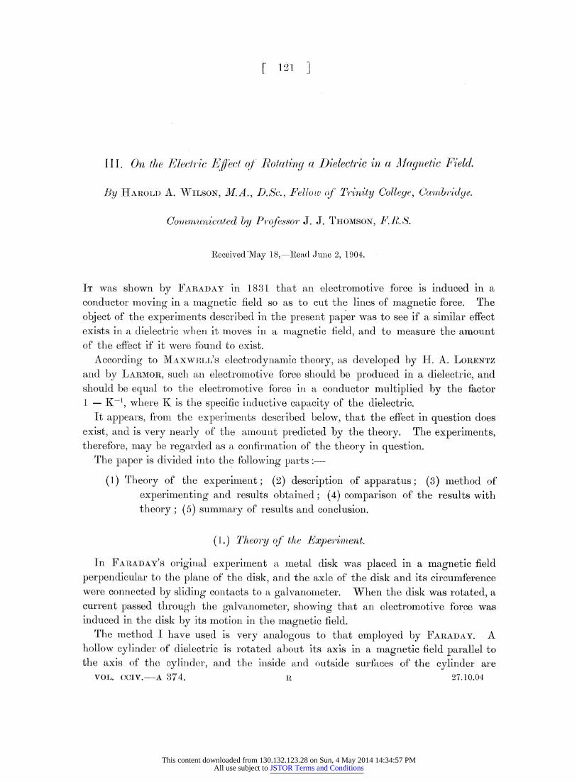
The apparatus was first set up in October, 1903, and the existence of the effect was almost immediately discovered. Various distu-rbing causes prevented accurate measurements being made, but these were ultimately nearly got rid of by suitable modifications of the apparatus. The apparatlis described below is the final form
F "'
C Fig. 1. AA, phosphor: bronze axle; BB, ebonite cylilner; CC, )rass tube; D1D, brass tube;
EE, vilcanised fibre tube; FF, revolution coun-ter disk; PP, driving pulley.
adopted, with which it was found possille to mlake imeasuremenlts of the induced electromotive force.
The dielectric cylinder used in the experiments was of ebonite, 9 97 centims. long, 4'15 centims. outside diameter, and 2 01 centtims. inside diamneter. It was mounted on a phosphor bronze axle, as shownr in fig. 1, which is drawn to scale.
/ - - - -- - -A- - - - - - -- - - - - - - -- - - - - - - - - - - - - - - - ?
A A %
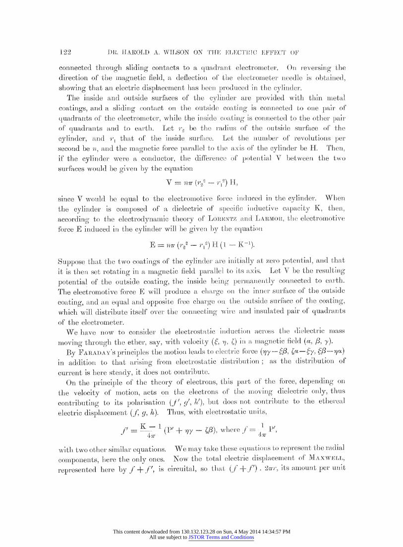
Fig. 2, AAAA, steel casting; BB, ebonite cylinder; CCCC, steel screws with cones; E, F, brushes;
HH, rod supporting revolution counter; JJ, plates closing end of solenoid; KK', ebonite blocks
supporting brushes; LL, tubes for water jacket; MI, revolution counter wheel; NNNN, lock nuts;
P, driving pulley; SSSS, magnetising solenoid; WWWW, water jacket.
The tube DD was insulated from the axle by thle tube EE of vulcanised fibre. The tube UDD was connected to earth durinog the experiments by a sliding contact
124
This content downloaded from 130.132.123.28 on Sun, 4 May 2014 14:34:57 PMAll use subject to JSTOR Terms and Conditions
ROTATING A I)IELECTRIC IN A MAIGNETIC FIELD.
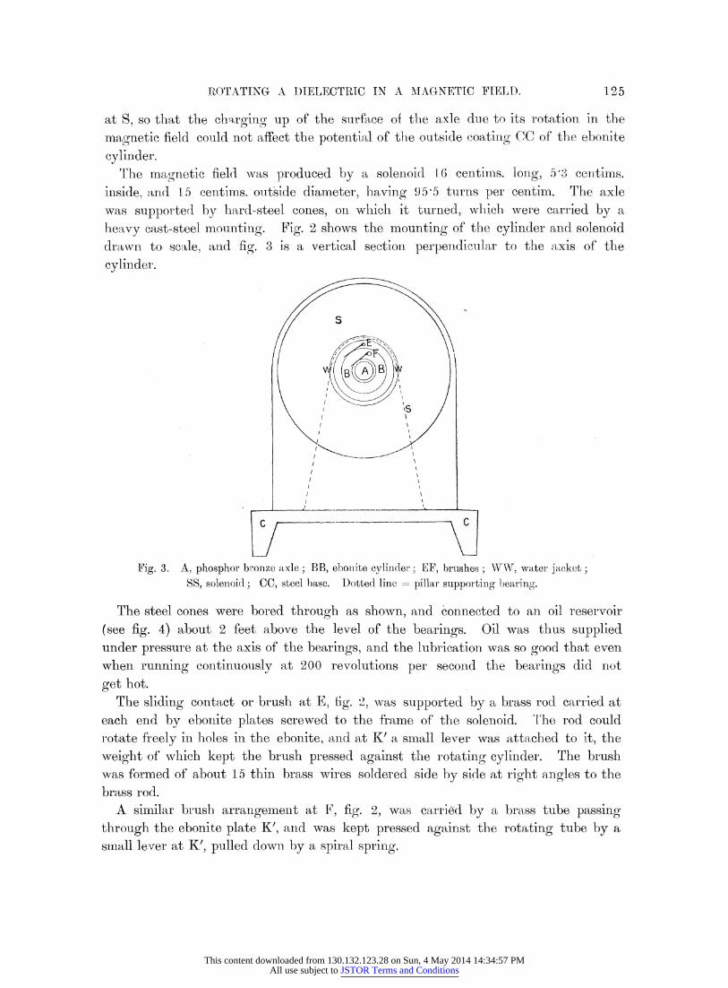
at S, so that the charging up of the surf.ace of the axle due to its rotation in the
magnetic field could not affect the potential of thle outside coating C( of the eboinite
cylinder. The magnetic field was produced by a solenoid 16 centiris. long, 5 3 cenltims.
inside, and 15 centims. outside diameter, having 95'5 turns per centim. The axle was supported by hlard-steel cones, on which it turned, which were carried by a
heavy cast-steel mounting. Fig. 2 shows the mounting of the cylinder and solenoid drawn to scale, and fig. 3 is a vertical section perpendicular to the axis of the
cylinder.
C - \
/
x
!\
Fig. 3. A, phosphor bronze axle; BB, ebonite cylinder; EF, brushes; WW, water jacket; SS, solenoid; CC, steel base. Iotted line = pillar supporting bearing.
The st;eel cones were bored through as shown, and connected to an oil reservoir
(see fig. 4) about 2 feet above the level of the bearings. Oil was thus supplied under pressure at the axis of the bearings, and the lubrication was so good that even
when running continuously at 200 revolutions per second the bearings (lid not
get hot. The sliding contact or brush at E, tig. '2, was supported by a brass rod carried at
each end by ebonite plates screwed to the frame of the solenoid. The rod could rotate fireely in holes in the ebonite, and at K' a small lever was attached to it, the
weight of which kept the brush pressed against the rotating cylinder. The brush was formned of about 15 thin brass wires soldered side by side at right angles to the
brass rod. A simlilar brush arrangement at Fi, fig. 2, was carried by a brass tube passing
through the ebonite plate K', and was kept pressed against the rotating tube by a small lever at K', pulled dowrn by a spiral spring.
This content downloaded from 130.132.123.28 on Sun, 4 May 2014 14:34:57 PMAll use subject to JSTOR Terms and Conditions
DR . HAROILD A. WILSON ON THE ELECTIrIC EFFECT OF
TI:he end JJ of the soletloid vwas closed by two semli-circuiar brass pllates screwed on0
as shown. These served to screel off electrostatic e-ffects (le to the driving belt
charging up. The inside surface of the solenoid wa,s kept cool by me-ans of the water jacket WVWWW, through which a rapid streanr of tap water was always kept flowing when the apparatus was in use. The water was made to flow in a spiral path round the solenoid by means of a spiral partition inside the jacket.
The solenoid was wound on a brass bobbin in two sections, and the windings wrere
carefully insulated from the bobbin. A current of 15 a5nmpBres could be passed for
some time through the -solenoid, using a P.D. of about 50 volts, without undue
heating. The cylinder was driven by a leather belt 2 centims. wide and 0.': centim. thick,
with a very well made splice. The belt was driven by a half horse-power continuous, current motor which ran at about 1450 revolutions per minute with 50 volts. Three
driving pulleys were used, 10 inches, 5 inches, and 2? inches respectively in diametelr.
The pulley on the cylinder shaft was 1-- inches in diameter, so that speeds of about
11,600, 5800 and 2900 revolutions per minute could be obtained.
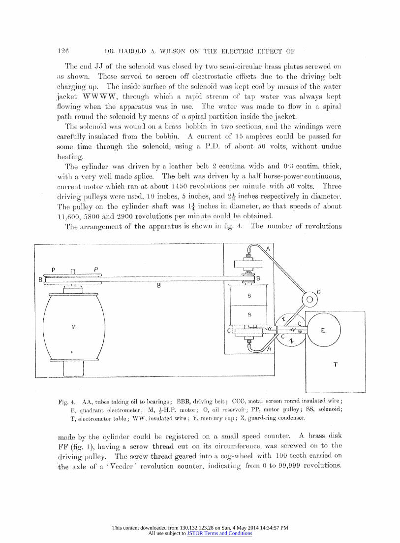
The arrangement of the apparatus is show\n in fig. 4. The numlnber of revolutions
]. g. 4 ... ... t
.1 i iiT _ __rr^'-^^^^zz^z^) ^ ^ _ __ ^, _ - -. -- -? - - _.-.-.^^s^^^s \ .0
CK E
Fig. 4. AA, tubes taking oil to bearings; BBB, driving belt; CCC, metal screen round insulated wire;
E, quadrant electromleter; M, ---.P. motor; 0, oil reservoir; PP, motor pulley; SS, solenoid;
T, electrometer: table; WW, ilnsulated wire; Y, merclry cup; Z, guard-ring condenser.
made by the cylinder could be registered on a small speed counter. A brass disk
FF (fig. I), having a screw thread cut on its circumiference, wVas screwe(d ol to t le
driving pulley. Trhe screw thread geared into a cog- wheel with 100 teeth carri-ed on
the axle of a 'Veeder ' revolution counter, indicating friom 0 to 99,999 revolutions.
12(6
This content downloaded from 130.132.123.28 on Sun, 4 May 2014 14:34:57 PMAll use subject to JSTOR Terms and Conditions
ROTATINC( A DIELECTRIC IN A MAG-NET4rC :iFIEL, D.
The spee(l counter was supported on a steel rod, so that it could be slipped up and (lown into position, and oil was suppliedl to the screw thread through a pipe leading to the oil reservoir. The number registered by the revolution counter in about 2 minutes was usually taken when determining the speed. It was found that the
speed observed agreed very nearly with that de(duced :froml the speed of the motor and size of the pulleys, and also that the speed rem-ained very constant for long intervals of time. In fact, no appreciable variation of the speed ever occurred (luring any of the experiments, the results of whichl are recorded in this paper.
The motor and solenoid were run fiom two differenlt sets of cells, so that varyilng the current in the solenoid did not affect the voltage on the motor. This latter voltage was always indicated by a Weston -voltmeter, so that if any change in it occurred, it was at once known that something was wrong. The current through the solenoid was measured by a very good Weston ammeter, which read from 0 to 20 amperes, and it could be reversed by means of a mercury-cup commutator.
''The motor and the apparatus described were screwed down to a large wooden board, whichl was supported on a stone slab in the Cavendish Laboratory. Heavy weights were placed o:n the board, and the apparatus was very steady, even -when
running at 200 revolutions per second. It remains now to describe the quadrant electrometer and its connections, and the
arrangement used for determining its sensibility. The quadrant electrometer used was of the Dolezalek type.: It was placed on a,I separate table standing on the
floor, and was not affectedl at all by the vibrations set up by the rotating cylinder. The quadrants were supported by " amberoid" pillars, which were found to insulate
very well. The needle was suspended by a quartz fibre, and wMas charged by touching it with a wire connected to one pole of a battery of secondary cells, the otlher pole of which was connected to the case and quadrants of the electrometer. N concave mirror 7 millims. in diameter was attached to the needle, and the deflection of the needle was observed by means of the image of an incandescent
lamp filament, formed by this mirroi on a mnillim. scale, distant 2 metres from the electrometer. The image was - millim. wide and perfectly sharply delined. Its
position could be easily read to - millim. The loss of charge by the needle t:hrough the surrounding air and the quartz fibre diminished the sensibility of the electro-
me,ter for potential difference about 50 per cent. in 24 hours. The needle was
usually charged uip to a potential of 40 volts, at whichl potential the sensibility for
quantity of electricity was a nlaximurm.
During the course of a series of measurements the sensibility of the electrometer, for quantity of electricity, was mleasure(d from time to timrie, but the variatiolns were
inappreciable, owing to the very slow rate at which the sensibility of the electro- meter, for quanltity, varied with the potential of the needle whllen the sensibility foil
quantity was lnear its m aximunIm value. The torsion of the quartz fibre used was just * I)OOLEZAIE1K, ' Zits. ffir Instrument.,' Deeember, 1901.
127
This content downloaded from 130.132.123.28 on Sun, 4 May 2014 14:34:57 PMAll use subject to JSTOR Terms and Conditions
DR. HAROLD A. -WILSON ON THE ELECTRIC E'FECT O'F
small enough to make the electrometer needle "dead-beat" when at the maximum
sensibility for quantity. The damping of the needle was done by the air inside the
quadrants. One pai,;r of the quadrants was always connected to the case and to earth, while
the other pair was connected, by a wire about 2 feet long, to the brush which made contact with the outside coating of the ebolite cylindere. This wire was completely enclosed in metal tubes, which, together witl- the electrometer case, the metal bobbin
of the solenoid and the inner coating of the ebonite cylinder, formed a complete metal:lic screenl, all conllected together and to earth, sur rounding the insulated parts of the apparatus. Outside electric disturbances had no effect whatever on the electrometer needle. For example, reversing the current through the solenoid was
repeatedly proved to produce no deflection of the electrometer needle when the
cylinder was not rotating. Also running the motor had no effect on the electro- meter.
rThe wire W7W (fig. 4) leading from the brushi to the electromneter was supported
by a sealing-wax rod and by anl arLranlgetelent which wras used to determine the
electrometerl sensibility for quantity. This consisted of a small circular parallel plate gutard-ring condenser, ZZ. The plates of thlis colndenser were held 2 00 centims.
apart by three ebonite pillars, and the lower plate and gutard ring were each 13 0 ceintims. in diameter. The hole inl the guard ring was 3'05 centims. in diameter and the
condenser plate 2'95 centimns. in diameter. rThe plates were all made of brass
0'5 centim. thick, and were turned up truly planle. lThe condenser pilate was sup-
ported by a disk of ebonite screwed down on the gu:ard ring, and it carried a rod, on
the top of which 'was a mercury cup, Y (fig. 4). The wire W W was supported
by this rod. A brass rod could be let down into the mercury cup when it was
desired to conn:ect the insulated parts of the apparatus to the metallic screen
surrounding them. This rod was soldered to a wire spring, the other end of which
was soldered to the tube containing the wire WW.
The larger plate of the condenser was coinnected with a colmmutator, by means of
which it could be either connected to earth or chartgedt up by means of a battery of
smnall secondary cells. To determine the sensibility of the electrometer for quantity the insulated parts
were first earthed and the larger plate of' the condenser charged to a potential of V volts. A quantity of electricity, q (q =- V/300 electrostatic units, where C is the
capacity of the guard-ring condenser), was thus induced on the small condenser plate. The rod at Y was then raised and the electrometer scale reading noted. The larger
plate of the condenser was then earthed, so setting free the quantity of electricity q on the insulated parts of the apparatus. The resulting deflection was then read off
and was taken to be the deflection due to the quantity of electricity q. It was
verified carefully that the deflection was proportional to q. The sensibility of the electrometer: for poteltial lifference -was measured when
128
This content downloaded from 130.132.123.28 on Sun, 4 May 2014 14:34:57 PMAll use subject to JSTOR Terms and Conditions
ROTATING A DIELECTRIC IN A MAGNETIC FIELD.
required by means of a potentiometer consisting of 100 resistance coils, each of 100 ohms resistance. A known P.D. was applied to the 100 coils in series and the deflection due to the P.D. on one or two of the coils measured.
(3.) Method of Expoerienting and Results.
The method of performing an experiment was very simple. The mlotor was started and the water set running through the water-jacket and the rate of revolution measured. lThe electrormeter quadrants and outside coating of the rotating cylinder were then insulated by pulling up the rod out of the mercury cup. The scale reading of the electrometer was then observed, and, if it remained steady, a current was passed through the solenoid and the resulting deflection noted. The current was then reversed several times and the corresponding deflections measured. The rate of revolution was measured again and then the motor stopped and the sensibility of the electrometer for quantity tested.
The difficulty in making these observations was that the index of the electrometer often did not rermain steady, but wandered about in a more or less irregular manner. The adoption of the water-jacket effected a great improvenment in this respect, but the chief point to be attended to in order to get the iindex steady was found to be the adjustment of the sliding contacts. In the first place it was found necessary to have the surfaces on -which the brushes pressed turned true very carefully, and the
bearings adjusted, so that there was no shaking ;when running. lThe trueness of these surfaces was tested as follows: the end of the lever attached to the rod carrying one of the brushes was observed with a low-power microscope and the
cylinder slowly rotated. If the surface was not true or the bearings loose, the lever moved up and down. The bearings were adjusted and the cylinder repeatedly re-turned until the levers remained steady on rotaPting slowly.
Another thing which reruiredir carefil adjustment was the pressure of the brushes on the moving surfaces. If the pressure was too great the surfaces got hot and a pyroelectric effect was produced which caused a continual drift of the electrometer index. In the earlier experiments the outside surface of the ebonite was coated with graphite to form a conducting coating. But after running a few minutes the graphite got rubbed off and the ebonite under the brush caught fire. A metallic coating therefore had to be used to conduct away the lheat generat;ed by the friction.
If the brushes were not sufficiently tightly pressed down the index also drifted continually, but in the opposite direction to the drift which appeared to be due to heating. The drift, when the brushes were not sufficiently tightly pressed down, was especially rapid when the surfaces were not true or the bearings loose. The cause of this drift is not certain, but it seems probable that it was due to the brush jumping on and off the surface and to particles of matter being torn off at each impact and carrying a charge away with them. This theory was confirmed by
VOL. CCIV.-A. S
129
This content downloaded from 130.132.123.28 on Sun, 4 May 2014 14:34:57 PMAll use subject to JSTOR Terms and Conditions
DR. HALOLD A. WILSON ON THEI ELECTICIC EFFECT OF
putting oil on the brushes, which was thrown ofr by the centrifugal force and caused a very rapid drift in the sanme direction as that obtained when the brus1hes w-ere not
pressed down enough. By carefully adjusting the bearings and brushes the index was got to remlain very fairly steady onl a numnber of' occasions and thle m1easuremnlents recorded below were obtain:ed. The pressure of the brushles was adjusted by hangling snmlnll weights on the levers.
If' the index was drifting slowly at a uniform r. ate, then measureiments could still be made by taking the deflection first in one direction and then in the other, and
taking -the mean of the two as being the true deflectiotn. Measurements got in tlhis
way agreed with those obtainled when tlhe i-ndex was steady, but the measuremlients
giveIn in the table below were obtained with the index very nearly steady, so that the deflections were nearly the same in either direction.
For exaimple, on one occasion a current of 7?5 amperes otn reversing gave a deflection
of 13 8 millims. one way and 13'0 millims. the other way. The index then began to drift and the deflections became 25 0 millins. onie way and 2'5 mil.limrs. th1e other way. The meani of the first pair is 13 4 millitms. and that oS the second patir 1 3.7 -millirns.
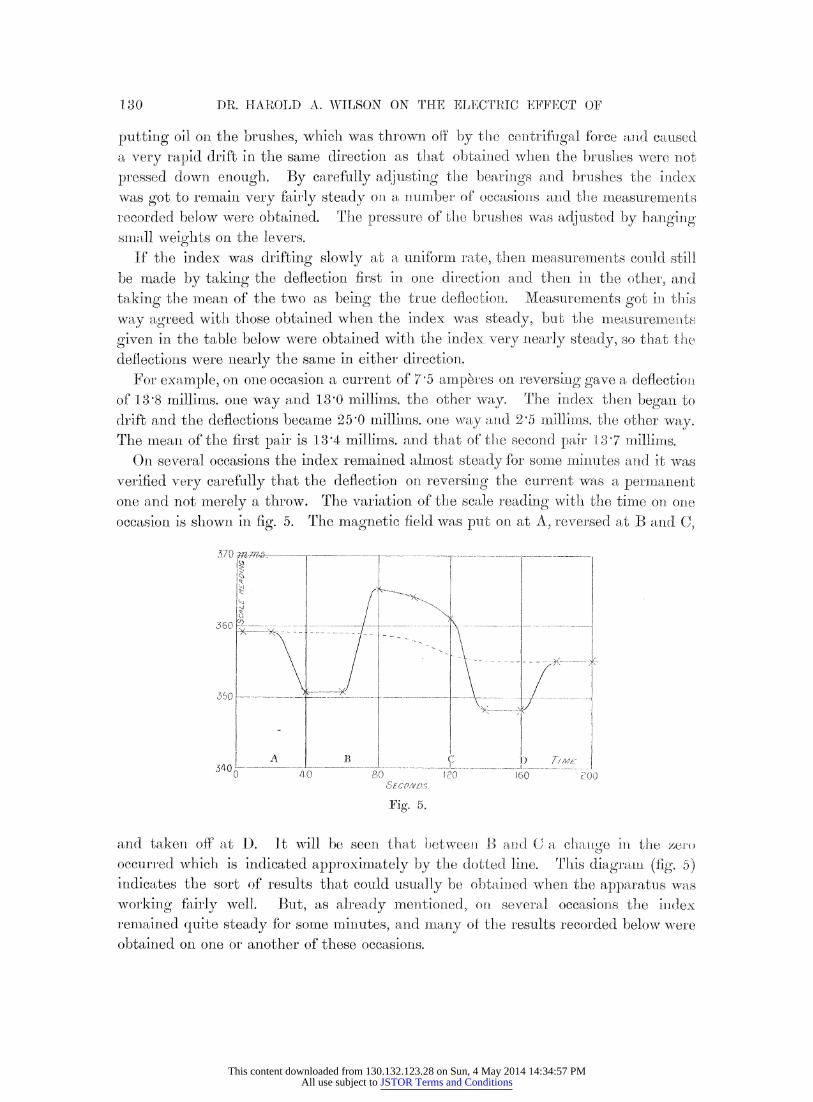
On several occasions the index remained almost steady for so:mte mnilnultes anld it vas
verified very carefully that the deflection oii reversilng the curreint was a permanlent one and not merely a throw. The variation of the scale reading with the time on olne occasion is shown in fig. 5. The magnetic field was put on at A, reversed at B and C,
370 _.
I :
350 -_o_,-------.:7: _ -- -..-.---.......--.--.
A B C 1D 'v
[____A ______ __B^ ^ _ _ ?? , P T/ME........ ..... .
O t0 0 i,o0 160 3( SE COVIJDS.
Fig. 5.
and takenl off at D. It will be seen that betw-een anl a nt-d chnge in:- the zeCro,
occurred which is indicated approximately by thle dotted line. 'his diagrla-n (fig. 5) indicates the sort of results that could usually be obtaiined. when the appar'atus mwas
working fairly well. But, as already mentioned, on several occasions the index reimained quite steady for some minutes, an-d mitany of tle results recorded below wnere obtained on one or another of these occasions.
1-30
This content downloaded from 130.132.123.28 on Sun, 4 May 2014 14:34:57 PMAll use subject to JSTOR Terms and Conditions
ROTATIN(G A IETLECTRIC IN A MAGNETIC FIELI).
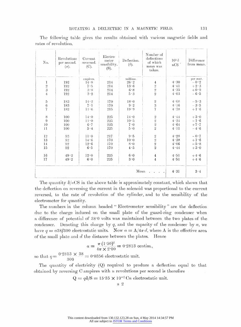
The following table gives the results obtained with various magnetic fields and rates of revolution. I ... .,.,....,..., I
N Number of Electro- Revolutions Current i,e deflectios l,T meter Deflection , ] 105 Daerence
No. per secondl. reversedt. . oef whisch I m e .er 1 ( sensibilitv. (I3 )nOCS froimy meani. i (C). (S). taken,
nmperes. millims per cent. 1 192 148 1 214 26 2 4 430 --0 2 2 192 7'5 214 13 6 2 4 41 +2 3 3 i 192 83 214 6 8 2 4' 35 +09 4 192 3 2 214 5 3 2 4 03 -65
5 I 183 142 ) 170 18 2 4-08 -5 3 6 i 183 7 -1 1 70 92 1 3 4- 16 -3 5 7 182 11 2 15 1.99 99 7 - 4 38 - 16
8 I 100 14-0 225 140 2 4 44 +3 -0 9 100 110 225 105 2 4'24 -1 6
10 100 6 7 225 7-0 2 4 64 + 7-7 H1 i 100 5-4 225 5 0 2 4 11 -4 6
12 93 110 217 95 2 4 28 -0 7 13 92 I 14-6 170 100 2 4-38 +1-6 14 92 1 126 1 170 8-0 2 4-06 - 58 15 92 6 e5 170 4 5 2 4 44 +3 0
16 49 -2 12-0 225 6-0 4 451 +4-6 17 49 2 60 225 3 0 4 4-51 +4 6
Mean .. . . 4 31 3 4
Trfhe quantity S/.oCS in the ab)ove table is approximlately constant, which shows that the deflection on reversing the current in the solenoid was proportional to the current
reversed, to the rate of revolution of the cylinder, and to the sensibility of the electrometer for quantity.
The numbers in the columnl headed " Electrometer sensibility " are the deflection due to the charge induced on the small plate of the guard-ring condenser when a difference of potential of 38 0 volts was maintained between the two plates of the condenser. Denoting this charge by q, and the capacity of the condenser by a, we have q -- a38/300 electrostatic units. Now a = A/4r cd, where A is the effective area of the small plate and d the distance between the plates. Hence
a .....7- ( -.50)-2- 0'2813 centim., 47r X 2'00
0'2813 X 38 so that 0283 0'0356 electrostatic unit. 300
The quantity of electricity (Q) required to produce a deflection equal to that obtained by reversing C amperes with n revolutions per second is therefore
Q r qS/S = 15'35 X 10-7 Cn electrostatic unit. s 2
131
This content downloaded from 130.132.123.28 on Sun, 4 May 2014 14:34:57 PMAll use subject to JSTOR Terms and Conditions
DR. HAROLD A. WILSON ON THE ELECTRIC EFFECT OF
(4.) Comparison of the Results Obtained winth the Theory.
In section (1) we obtained an expression for the electromotive force (E) in the
ebonite, which was E = V (C +- C')/C. Now V (C - C') is the quantity of electricity required to produce a deflection equal to that (c ue to E, so that, supposing that Q is all produced by E, we get, theoretically, Q =: EC.
Now E = (1 - K-') v'nH (rj2 r'-2), so tha-t E should be prloportional to n and HE and H is proportional to C, so that, theoretically, Q should vary as Cn in agreementl with the results obtained.
The direction of E should be theoretically the saime as the induced electromnotive force in a conductor moving in a magnetic field. It was verified repeatedly when
doing the experiments that the sign of the charge indicated by the observed
deflections was the same as would ha,ve been obtainr-ed if the rotating cylinllder had
been a conductor. The results obtained are therefore in complete agreement wit}h the theory, as regards the direction of the effeet and its variation- with the mag-etic field and rate of revolution.
To complete the comparison of the results with the theory, it is necessary to calculate the magnitude of the effect which ought to be obtained according to the
theory with the apparatus use(l. The sinmple formnula E = r (t - K-') H (r2 - r) cannot be used for this purpose, because in the actual apparatus H was not uniform,
owing to the finite length of the solenoid. Furlther, the induced electromotive forces in the conducting coatings of the cylinder have to be calculated, and the small effects due to them added to the effect due to the electromotive force in the ebonite to
obtain the full theoretical value of the observed effect. The quantities to be determined are therefore: (t) the capacity C of the ebonite cylinder; (2) the specific inductive capacity of the eboniite; and (3) the distributi;oni of the mnagnetic :field due to the solenoid in the region occupied by the cylinder. The determination of (1) and
(2) will first be described. To determine the capacity between the inside and outside coatings of the cylinder,
the inside coating was connected through a commutator to a potentiometer, so that
it could be charged up when required to a known potential. The outside coating was
first connected to earth and then the inside coating charged up. The outside coating was then insulated and the inside coating put to earth. The resulting deflection of
the electrometer gave the charge induced on the outside coating in terms of the
electrometer sensibility, as determined by niea:is of the small guard-ring condenser.
The deflection due to chargirng the inside coating to 0 400 volt on one occasion was
185 millims. The electrometer sensibility was then 0-000184 electrostatic unit per millimetre, so that the capacity required is 300 X 185 X 0-000184 - 0-400 = 25 5
centims. The mean of several determinlations done during the course of the experi- ments was 25'4 centims.
To determine the specific inductive capacity of the ebonite, the outside coating was
1.32
This content downloaded from 130.132.123.28 on Sun, 4 May 2014 14:34:57 PMAll use subject to JSTOR Terms and Conditions
ROTATING A DIELECTRIC IN A MAGNETIC FIELD).
cut into three parts and the capacity of the middle part found in the way just described, using the end parts as guard rings. The electrometer sensibility was 0 000150 electrostatic unit per millimetre, and charging the inside coating to 0'400 volt gave a deflection of 107 millims. The capacity of the middle part was therefore 12'0 centims. The length between the centres of the two cuts (each 2 millim. wide) in the outside coating was 4'95 centims. The capacity of the cylinder per unit length was therefore .0 =- 2 425 centims. Now the capacity per
unit length is ------; hence K = 2 log r2/rl X 2 425, or K = 4'85 log 4 5 - 3 54. 2 log ri',l
9 2'01
The value obtainetl for K depends on the time allowed to elapse between dis-
charging the inside coating and reading the electromneter deflection. This is due to t,he leaking out of residual charge from the ebonite. In the experiments on the effect due to rotating the cylinder in a mnagnetic field the deflection of the electro- meter was read as soon as the index came to rest after reversing the field. In
mneasurinlg the specific inductive capacity, therefore, the same planl was adopted, so that tlhe specific inductive capacity obtained corresponds to a time of discharge equal to the timne taken by the electroneter index to move firomn the zero position to its new position. The electrometer needle was just dead-beat, so that this time was
fairly constant and was about 15 seconds.
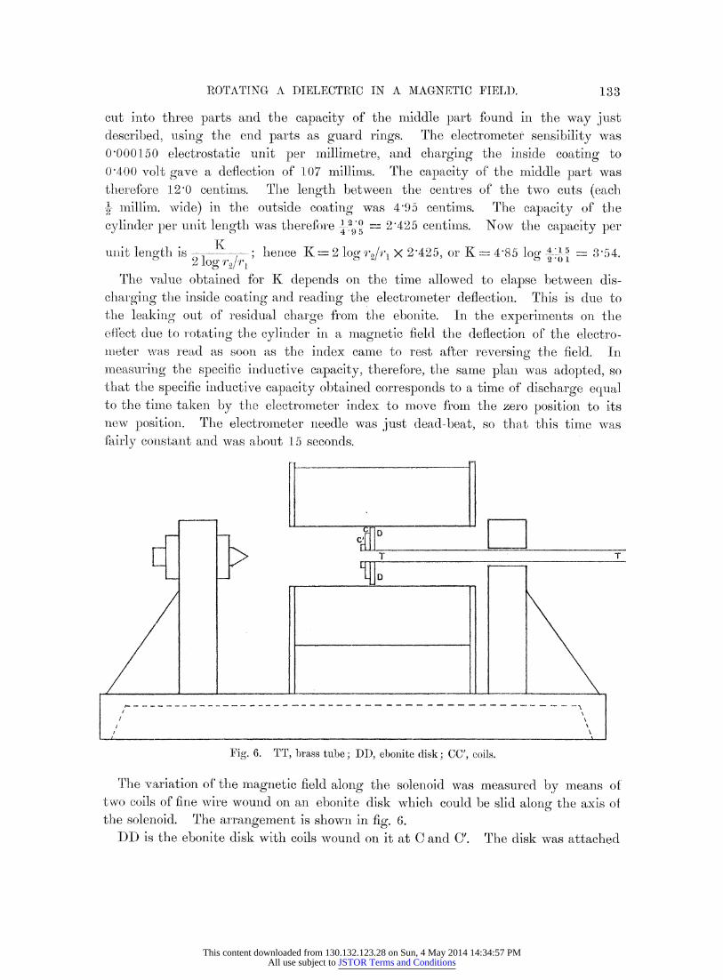
Fig. 6. TT, brass tube; DD, ebonite disk; CC', coils.
The variation of the magnetic field along the solenoid was measured by means of two coils of fine wire wound on an ebonite disk which could be slid along the axis of the solenoid. The arrangement is shown in fig. 6.
DD is the ebonite disk with coils wound on it at C and C'. The disk was attached
133
This content downloaded from 130.132.123.28 on Sun, 4 May 2014 14:34:57 PMAll use subject to JSTOR Terms and Conditions
DR. HAROLD A. WILSON ON THE ELECTRIC EFFECT OF
as shown to a brass tube TT, through which the wires leading to the coils were
brought out. The coil C consisted of a single layer of fine silk-covered wire having 9 turns, and its mean diameter was 4 28 centims. The ends of the wire were
twisted together and connected to aii Ayrton-Mather ballistic galvanometei. I
coil C' was similar to C, and its mean diameter was 2'01 centims. The deflectiovn of'
the galvanometer coil, due to reversing a known current in the solenoid, was cdetcr- mined for each of the coils 0 anid C' at a series of positioiis along the axis of the
solenroid. The coils C and C' were then put at the centre of a solenoid, 50 centims.
long and 5'4 centimns. in diameter, consisting of a sinigle layer of wire, with 42'3 5
turns per centimetre, wound on a brass tube. Known cu:rrents were thei- reversed in this long solenoid and the galvanom,eter deflections with the coils C and C'
measured. The current was passed along the Ira -s tube to neutralize the field due
to the component of the current along the solenoidc. The field strength at the centre
of this solenoid was calculated, and so the sensibility of' the galvanometer with each
of the coils C and C' was obtained. The magnetic field due to the solenoid used to
produce the field in- which the cylinder was rotated was found to be proportional to
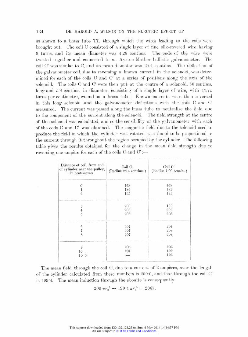
the current through it throughout the region. occupied by the cylicder. cThe following
table gives the results obtained for the change in the mean field strength due to
reversing one ampbre for each of the coils C and C .:---
Distance of coil, from endoil Coil ' of cylinder near the pulley, t (Radius 2'14 cent, ims.) (Radius 1'00 centim.) in centimetres.
----- ------
0 168 1.68 1 1.86 183 2 195 193
3 200 1.99 4 203 202 5 206 205
6 207 207 7 207 208 8 | 207 208
9 205 205 10 201 199 10-3 -- I 196
The mean field through the coil C, (nue to a currentt of 2 amnperes, over the length of the cylinder calculated from these numnbenrs i 2000, aind that tbrough the coil C'
is 199'4, The mean induction through the ebonite is consequently
200 iTrrj- - 199-4 /':?- == - '2067.
134
This content downloaded from 130.132.123.28 on Sun, 4 May 2014 14:34:57 PMAll use subject to JSTOR Terms and Conditions

ROTATING A DIELECTRIC IN A MAGNETIC FIELD.
The tmeain induction through the outside coating is v (wr - r2)) 200 132, where r3 is the radius of the outside coating. HIere 2r - 4'25, 2r4, = 4'15 and( 2i1 = 2'01 centims.
The lquantity which lhas been deternmined:l experimentally is the charge which, when
given to the outside coatting, will produce a deflection- equal to that observed on
reversing the miagnetic field. Now, if both the brushes were connected to earth, the
charge induced on the outsi(de coating -would be equal and opposite to this charge which has been (letermined. This follows at once from the equation EC - V (C + C ') Q, because wrhen bothL surfauces of the cylinder are at zero potential the induced charge is evidently - EC, E being understood just now to include the induced electromotive forces in the coatings as well as the induced electronmotive force in the ebonite.
The brushl on the outside surface wras at the centre of the cylinder, where the field strelngth is 206. Consequently the outside surface of the cylinder had a mean potential, C1 (206 - 200) wr.3 = + 85 Cn electromagnetic units below that of the brush. The miean potential of the inside surface of the outside coating was therefore + (132 + 85) C + 217 CGn electromagnetic units below the brush. The field at the brush on the inside coating was 196, so that the mnean potential of the inside coating was Cn (1 99 4-- 1'96) vrl -= 11 Cmn electromagnetic units above that of the brush. The capacity between the inside and outside surfaces was 25 4 centims., and that between the outside surfiace and the surrounding tube 24 centims. Consequently the charges induced on the outside coa-ting, when both brushes were earthed, were
Q'" = Cn (217 + 11) 25*4/3 X 1010 electrostatic units
on the inside surftace, due to the electromotive forces in the coatings.
Q"- Cn (+- 85) 24/3 X 1010 electrostatic units
on the outside surf'ace, due to the electroimotive force in the outside coating, and
Q' :: (1 - K-1) Cm (2067 X 25'4)/3 X 10:0 electrostatic units
on the inside surface, due to the electromotive force in the ebonite. These equations
give, since K =- 3 54,
Q'1-t2l'58 X -10-7 Cn, Q"'=0o-68 X 10-7 C. Q"==/ 1 -93 X 10-7 Cn electrostatic unit.
Thus the total char -ge onl the outside coating was 1 5 1L9 X 1 0 7 Cn, antid this should be equal to Q, lwich was found experimentally to be 15'35 X .10-T7 C(1 electrostatic unit. It thus appears that the clharge, as calculated by the theory, agrees with that found within the limits of experimental error. The difference between the effect calculated and the mean effect found is only I per cent. Subtracting Q" and Q"' from the effect found we get 12-74 X 10-7 Cn electrostatic unit, which may be
regarded as the experimental value of the effect due to the ebonite alone. The corrections Q" and Q"' though somewhat large are not open to any doubt, because
135
This content downloaded from 130.132.123.28 on Sun, 4 May 2014 14:34:57 PMAll use subject to JSTOR Terms and Conditions
DR. HAROLD A. WILSON ON THE ELECTRIC EFFECT OF
tlhe induced elect:romotive force in a conductoir whe1n mnoving in a miagnetic field is
accurately klnown.
The equation Q' = _ 2 - X (1 - K-) Cn can be used to calculate K1 from
3 X 10
the experimentally-found value for Q'. It gives K- 3'68, which is 4 per cent.
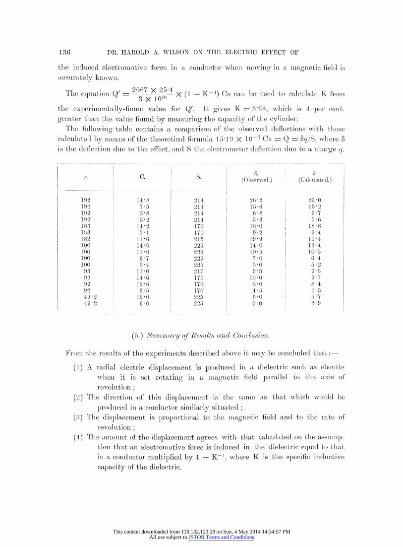
greater than the value found by measuring the capacity of the cylinder. The followinrg table containis a comparison of tlhe obselrved deflections with those
calculated by mea:ts of the theoretical for-mulla 1 51.9 X 10'-7 Ca Q =- Sq/S, wlwhlere 8
is the deflection due to the effect, and S the electrometer deflection due to a charge q.
'lb.
192 192 192 192 183 ]83 182 100 100 100 100 93 92 92 92 49-2 49 2
C.
14-8 7.5 38 3'2
14 2 7-1
11 6 14 0 11 0
67 5-4
11 0 14 6 12 6
6'5 12 0 6 0
S.
214 214 214 214 170 170 215 225 225 225 225 217 170 170 170 225 225
(Observed.)
26 2 13 6 6 8 5 3
18'0 9'2
19'9 14 0 10-5 7-0 5 0 9-5
10'0 8'0 4,5 6 0 3-0
.
(Calculated.)
26-0 13-2 6 7 5 6
18 8 9.4 19 4 13 4 10'5 6 4 5 2 9 5 9 .7 8-4 4.3 5,7 2-9
(5.) Suqn1~mtary of 1Res8lts ancd Uoclusion,
From the results of the experiments described above it miay be concluded thiat:-
(1) A radial electric displacement is produced in a dielectric such as ebonite wThen it is set rotating ini a mlnagnetic field parallel to the axis of
revolution;
(2) The direction of this displacemenit is the same as thtat whiclh would be
produced in a conductor similarly situated; (3) The displacernent is proportional to the mllaginetic field and to the rate of
revolution;
(4) Thle amount of the displacelment agrees with that calculated on the assumlp-
tion that an electromotive force is induced in the dielectric equal to that in a conductor multiplied by 1 - K-', where K is the specific inductive
capacity of the dielectric.
1-36
This content downloaded from 130.132.123.28 on Sun, 4 May 2014 14:34:57 PMAll use subject to JSTOR Terms and Conditions
ROTATING A DIELECTRIC IN A MAGNETIC FIELD.
The results obtained are consequently in complete agreement with MAXWELL'S
electromagnetic theory, as developed by H. A. LOR1ENTZ and LARMOt.
According to HEaTZ'S form of MAXWELL'S thleory the inducetd electromotive force
in a dielectric is equal to that in a conductor. The experiment described may consequently be regarded as a crucial experiment deciding in favour of LOuRENTZ and
LARMOR'S theory and against HERTZ'S theory.
In conclusion, I wish to say that I am indebted to Professor LARMOR for valuable advice and help with regard to the theory of the experiment. My best thanks are also due to Professor J. J. Tl'OMSON fol his never failing encouragement and valuable
suggestions given throughout the course of the work, which was done in the Cavendish
Laboratory.
VOL. CCIV. ---A.
137
T
This content downloaded from 130.132.123.28 on Sun, 4 May 2014 14:34:57 PMAll use subject to JSTOR Terms and Conditions